EP1132855A2 - Input device and portable electronic device using the same - Google Patents
Input device and portable electronic device using the same Download PDFInfo
- Publication number
- EP1132855A2 EP1132855A2 EP01301998A EP01301998A EP1132855A2 EP 1132855 A2 EP1132855 A2 EP 1132855A2 EP 01301998 A EP01301998 A EP 01301998A EP 01301998 A EP01301998 A EP 01301998A EP 1132855 A2 EP1132855 A2 EP 1132855A2
- Authority
- EP
- European Patent Office
- Prior art keywords
- operating
- operating member
- rotary electric
- electric part
- rotor
- Prior art date
- Legal status (The legal status is an assumption and is not a legal conclusion. Google has not performed a legal analysis and makes no representation as to the accuracy of the status listed.)
- Withdrawn
Links
Images


Classifications
-
- G—PHYSICS
- G06—COMPUTING; CALCULATING OR COUNTING
- G06F—ELECTRIC DIGITAL DATA PROCESSING
- G06F3/00—Input arrangements for transferring data to be processed into a form capable of being handled by the computer; Output arrangements for transferring data from processing unit to output unit, e.g. interface arrangements
- G06F3/01—Input arrangements or combined input and output arrangements for interaction between user and computer
- G06F3/03—Arrangements for converting the position or the displacement of a member into a coded form
- G06F3/033—Pointing devices displaced or positioned by the user, e.g. mice, trackballs, pens or joysticks; Accessories therefor
- G06F3/0362—Pointing devices displaced or positioned by the user, e.g. mice, trackballs, pens or joysticks; Accessories therefor with detection of 1D translations or rotations of an operating part of the device, e.g. scroll wheels, sliders, knobs, rollers or belts
-
- H—ELECTRICITY
- H01—ELECTRIC ELEMENTS
- H01H—ELECTRIC SWITCHES; RELAYS; SELECTORS; EMERGENCY PROTECTIVE DEVICES
- H01H19/00—Switches operated by an operating part which is rotatable about a longitudinal axis thereof and which is acted upon directly by a solid body external to the switch, e.g. by a hand
- H01H19/02—Details
- H01H19/10—Movable parts; Contacts mounted thereon
- H01H19/14—Operating parts, e.g. turn knob
- H01H2019/146—Roller type actuators
Definitions
- the present invention relates to an input device for use in a portable electronic device such as a portable telephone set, as well as a portable electronic device using the input device.
- a rotary electric part 50 is constituted by a rotary encoder, and an insulating base 51 formed by molding a synthetic resin and constituting the rotary electric part 50, is provided with a substrate portion 51b having a central circular hole 51a, with plural contact pieces 52 being embedded in the substrate portion 51b.
- a rotor 54 of the rotary electric part 50 which rotor is formed by molding a synthetic resin, is provided with a disc portion 54a, shaft portions 54b and 54c projecting from both sides of the disc portion 54a, and a hexagonal, non-circular through hole 54d formed in a central part of the rotor 54.
- Code patterns 55 are formed on a surface of the disc portion 54a.
- the conventional input device has a push-switch 56.
- the push-switch 56 is provided with a housing 56a formed by molding a synthetic resin and with a contact portion (not shown) housed therein and is also provided with a push-button 56b attached to the housing 56a movably.
- the push-switch 56 is mounted to the printed circuit board P2 in a predetermined spaced position from the rotary electric part 50.
- An operating member 57 is provided with an operating portion 57a of a large diameter, shafts 57b and 57c projecting from both sides of the operating portion 57a, and a regular hexagonal sphere portion 57d formed at one end of the shaft 57b.
- the conventional input device since one rotary electric part 51 and the push-switch 56 are operated by one operating member 57, the number of functions available is small and thus the conventional input device is unsuitable for a portable electronic device for which various functions are required and is not convenient for use.
- an input device comprising a first operating member for operating a first rotary electric part, the first operating member being rotatable, and a second operating member for operating a second rotary electric part, the second operating member being also rotatable, the first and second operating members being each provided, on an outer peripheral portion in an axial direction thereof, with an operating portion for performing an operation in a direction orthogonal to the axial direction, the first and second operating members being disposed so as to be positioned close to each other in one and the same plane and so that the respective axial directions are orthogonal to each other.
- the first and second operating members are arranged in L shape.
- one of the first and second operating members can tilt with the associated first or second rotary electric part as fulcrum when pushed in a direction perpendicular to the axial direction thereof, and a push-switch is operated by the tilting motion.
- a portable electronic device comprising a case having a display in a front wall thereof, a first operating member for operating a first rotary electric part disposed within the case, the first operating member being rotatable, and a second operating member for operating a second rotary electric part disposed within the case, the second operating member being also rotatable, the first and second operating members being each provided, on an outer peripheral portion in an axial direction thereof, with an operating portion for performing an operation in a direction orthogonal to the axial direction, the first and second operating members being disposed so as to be positioned close to each other in one and the same plane, allowing the respective operating portions to be partially exposed from the front wall of the case, and so that the respective axial directions are orthogonal to each other.
- the first and second operating members are arranged in L shape.
- one of the first and second operating members can tilt with the rotary electric part as fulcrum when pushed in a direction perpendicular to the axial direction thereof, and a push-switch is operated by the tilting motion.
- both the first and second operating members can tilt with the rotary electric part as fulcrum when pushed in directions perpendicular to the respective axial directions, and a push-switch is operated by the tilting motion.
- an input device comprising a first rotary electric part having a rotor, a first operating member for operating the first rotary electric part, the first operating member having a first shaft fitted in a non-circular hole formed in the rotor of the first rotary electric part, a second rotary electric part having a rotor, and a second operating member for operating the second rotary electric part, the second operating member having a second shaft fitted in a non-circular hole formed in the rotor of the second rotary electric part, the first and second operating members being positioned in alignment with each other.
- the first operating member is further provided with an operating portion and a third shaft
- the second operating member is further provided with an operating portion and a fourth shaft, the third and fourth shafts being located respectively on the sides opposite to the first and second shafts with respect to the operating portions and in proximity to each other.
- one push-switch is disposed below the third and fourth shafts so as to straddle both shafts, the first or the second operating member tilts when pushed in a direction perpendicular to its axial direction, and the push-switch is operated thereby.
- a portable electronic device having an input device, the input device comprising a first rotary electric part having a rotor, a first operating member for operating the first rotary electric part, the first operating member having a first shaft fitted in a non-circular hole formed in the rotor of the first rotary electric part, a second rotary electric part having a rotor, and a second operating member for operating the second rotary electric part, the second operating member having a second shaft fitted in a non-circular hole formed in the rotor of the second rotary electric part, the first and second operating members being positioned in alignment with each other.
- the rotary electric part D used in this embodiment is formed as a rotary encoder.
- An insulating base 1, which is formed by molding an insulating material, is made up of a rectangular main base portion 2, a side wall portion 3 which is upright at right angles from the main base portion 2, and a pair of sub-base portions 5 connected respectively both sides of the main base portion 2 through thin-walled portions 4.
- the main base portion 2 is provided with recesses 2a formed respectively in end faces on both sides, a cylindrical protrusion 2b formed centrally on a front end face, and a pair of retaining portions 2c formed on a lower surface of the main base portion and each having a tapered portion.
- the side wall portion 3 is formed upright from corners of an upper surface of the main base portion 2.
- the side wall portion 3 is provided with a central circular hole 3b having a flange 3a, a pair of relief holes 3c extending from both sides of the hole 3b up to the main base portion 2, a pair of upper walls 3d extending perpendicularly from an upper position, a groove 3e formed between the paired upper walls 3d, retaining portions 3f formed respectively on upper surfaces of the paired upper walls 3d, and protrusions 3g.
- Each of the paired sub-base portions 5 is provided with a convex portion 5a formed on an end face and having a roundish end.
- a plurality of contact pieces 6 each formed by a metallic plate are each provided with a contact portion 6a and a terminal portion 6b.
- the contact pieces 6 are respectively embedded in the sub-base portions 5.
- the contact portion 6a projects upward from an upper surface of the insulating base 1, while the terminal portion 6b projects downward from a lower surface of the insulating base 1 and a flat surface of an outer end thereof is bent so as to be positioned in parallel with and at substantially the same position as one end of the insulating base 1, i.e., the side wall portion 3.
- the common contact piece 7 is embedded in the main base portion 2 at a position close to the side wall portion 3.
- the contact portions 7a project upward from the upper surface of the insulating base 1 and are positioned in the relief holes 3c of the side wall portion 3, while the terminal portion 7b projects downward from the lower surface of the insulating base 1.
- each embedded contact piece 6 straddles the main base portion 2 and the associated sub-base portion 5 and constitutes each thin-walled portion 4 as a connection between the main and sub-base portions 2, 5.
- a metallic plate separate from that of the contact piece 6 may be embedded in the insulating base 1 to form each thin-walled portion 4. Further, the thin-walled portion 4 may be formed by the insulating material of the insulating base 1.
- a cylindrical rotor 8 which is formed by molding an insulating material, comprises a shaft portion 8a provided on one end side, a holding portion 8b formed contiguously to the shaft portion 8a and having a diameter larger than the diameter of the shaft portion 8a, a concave-convex portion 8d for clicking which is formed on an end face 8c on one side of the holding portion 8b which end face is orthogonal to a rotational axis direction of the rotor, and end face 8e positioned between the shaft portion 8a and the holding portion 8b on an opposite side of the holding portion, the end face 8e being orthogonal to the rotational axis direction of the rotor, and a non-circular, hexagonal hole 8f formed centrally.
- a code member 9 which is formed by a metallic plate, is provided with a ring-like plate portion 9a which forms a common pattern and a plurality of tongue pieces 9b which are bent from an inner periphery of the plate portion 9a and which form code patterns, as shown particularly in Fig. 11.
- the code member 9 is embedded or press-fitted into the rotor 8.
- the ring-like plate portion 9a which forms a common pattern is positioned at the end face 8e of the rotor 8, while the tongue pieces 9b which form a code pattern are exposed to an outer circumferential surface of the holding portion 8b.
- the tongue pieces 9b extend in an axial direction G1 of the rotor 8.
- the shaft portion 8a is fitted in the hole 3b loosely so as to create a small clearance K1, thereby permitting the rotor 8 to perform a tilting motion with respect to the insulating base 1.
- the paired contact portions 7a of the common contact piece 7 are opposed to the end face 8e and are in contact with the plate portion 9a as a common pattern of the code member 9.
- the plural contact pieces 6 are positioned on opposite sides with the circumferential surface of the rotor therebetween and come into and out of contact with the tongue pieces 9b as code patterns of the code member 9, and a pair of contact portions 6a are brought into contact with the code patterns with a phase difference.
- the contact pieces 6 are located perpendicularly to the axial direction G1 and are put in sliding contact with the code patterns.
- An engaging member 10 which is formed by a metallic plate, comprises a rectangular plate-like base portion 10a, an engaging portion 10b formed by cutting and bending a central part of the base portion 10 in a C shape, the engaging portion 10b having convex portions at free ends thereof, a circular hole 10c formed in a lower position of the base portion 10a, a pair of side plates 10d bent from both sides of the base portion 10a, cut and raised portions 10e formed in the side plates 10d respectively, a T-shaped upper-side plate 10g bent from an upper side of the base portion 10a and having a retaining portion 10f at a free end thereof, and a C-shaped lower-side plate 10j bent from a lower side of the base portion 10a and having a rectangular hole 10h formed centrally.
- the engaging member 10 is aligned with the insulating base 1 so that the engaging portion 10b becomes opposed to the end face 8c of the rotor 8 having the concave-convex portion 8d, and then the protrusion 2b is inserted into the hole 10c.
- the upper-side plate 10g is positioned on the upper walls 3d of the side wall portion 3 and is pushed in, allowing the retaining portion 10f to be engaged with the retaining portions 3f. Further, the upper-side plate 10g is positioned in the groove 3e and is secured to the side wall portion 3.
- the lower-side plate 10j is positioned on the lower surface of the main base portion 2 and is pushed in, allowing the retaining portions 2c to be positioned in the hole 10h, whereby the lower-side plate 10j is locked to the retaining portions 2c and the lower-side plate 10j is secured to the main base portion 2.
- the engaging member 10 is mounted at both upper and lower positions relative to the rotor 8, while the side plates 10d are located at right and left positions respectively relative to the rotor 8.
- the convex portions of the engaging portion 10b are engaged disengageably with the concave-convex portion 8d formed on the end face 8c of the rotor 8, constituting a click mechanism.
- the engaging member 10, the contact pieces 6 and the common contact piece 7 extend toward the rotor 8 with the insulating base 1 as a reference plane.
- An encoder body E1 is formed by such a configuration.
- a mounting plate 12 which is constituted by a solderable metallic plate, comprises a flat plate portion 12c, the flat plate portion 12c having a cylindrical portion 12h formed with a large circular hole 12a centrally and also having a small hole 12b in a lower position, a pair of arm portions 12d bent opposedly from both sides of the flat plate portion 12c, rectangular holes 12e formed centrally of the arm portions 12d respectively, mounting portions 12f bent from side ends of the arm portions 12d, and projecting portions 12g provided on the mounting portions 12f side of the flat plate portion 12c.
- the mounting plate 12 is positioned on the engaging member 10 side of the encoder body E1 and the cylindrical portion 12h is positioned within the rotor 8, then in this state the protrusion 2b of the insulating base 1 is inserted into the small hole 12b.
- the arm portions are pushed inwards on the side plates 10d of the engaging member 10, so that the cut and raised portions 10e are positioned in the holes 12e respectively and the arm portions 12d are engaged with the cut and raised portions 10e, whereby the mounting plate 12 is snap-fastened to the engaging member 10.
- the mounting plate 12 When the mounting plate 12 is thus mounted, the flat plate portion 12c is superimposed outside the plate-like base portion 10a of the engaging member 10, the arm portions 12d are mounted to the side plate 10d respectively at right and left positions with respect to the rotor 8.Lower surfaces of the mounting portions 12f bent from side ends of the arm portions 12d which extend in the axial direction G1 of the rotor 8 are located at approximately the same position as the L-shaped terminal portions 6b and 7b of the contact pieces 6 and the common contact piece 7 both extending from the lower surface of the insulating base 1.
- a clearance K2 is formed between the cylindrical portion 12h and the rotor 8, the clearance K2 being larger than the clearance K1.
- the rotor 8 is brought into abutment against the side wall portion 3 by the engaging member 10.
- the undersides of the main- and sub-base portions 2, 5 are brought into opposition to a printed circuit board P1 and the projecting portions 12g are inserted into holes 13 formed in the printed circuit board P1, whereby the rotary electric part D is established its position.
- the terminal portions 6b and 7b of the contact pieces 6 and the common contact piece 7, and the mounting portions 12f of the mounting plate 12 are positioned on wiring patterns (not shown) formed on an upper surface of the printed circuit board P1.
- the contact pieces 6, the common contact piece 7 and the mounting plate 12 thus constituted are surface-mounted to the wiring patterns by creamy solder and thus mounted to the printed circuit board P1, whereby the rotary electric part D is mounted to the printed circuit board in parallel with the axial direction G1 of the rotor 8.
- the concave-convex portion 8d of the rotor 8 performs engaging and disengaging motions for the engaging portion 10b to effect a click motion, the tongue pieces 9b come into and out of contact with the contact pieces 6, and the common contact piece 7 contacts the plate portion 9a constantly, with consequent generation of a two-phase pulse signal between the contact pieces 6 and the common contact piece 7.
- first and second rotary electric parts D1, D2, as the rotary electric part D constituted as above, are mounted to the printed circuit board P1 spacedly in alignment with each other through mounting plates 12 which are opposed to each other, as shown in Fig. 1.
- a push-switch 15 is made up of a housing 16 which houses a contact portion (not shown) therein and a push-button 17 which is secured to the housing 16 vertically movably and which is urged upwards constantly.
- the push-switch 15 is mounted to the printed circuit board P1 at a position intermediate between the first and second rotary electric parts D1, D2 and on an extension of the axial direction G1.
- First and second operating members 18, which are formed by molding a synthetic resin, each comprise a cylindrical operating portion 18a of a large diameter, a first cylindrical shaft 18c and a third cylindrical shaft 18d (or a second cylindrical shaft 18c and a fourth cylindrical shaft 18d) smaller in diameter than the operating portion 18a, the shafts 18c and 18d projecting in an axial direction G2 of the operating member 18 from central positions of both side faces 18b of the operating portion 18a, and a hexagonal, non-cylindrical, non-circular portion 18e formed at an end portion of the first (or the second) shaft 18c.
- the first and second shafts 18c of the first and second operating members 18 are respectively inserted into the holes 12a from the mounting plates 12 side while being guided by the cylindrical portions 12h, and the non-circular portions 18e are fitted respectively in the non-circular holes 8f of the rotors 8.
- the third and fourth shafts 18d of the first and second operating members 18 are positioned close to each other and are simultaneously supported by the upper wall 19b.
- the tilting motion of the first operating member 18 is performed in the following manner.
- Fig. 2 when the operating member 18 is pushed, first a lower portion of the shaft 8a of the rotor 8 comes into abutment with the side face of the insulating base 1 which defines the hole 3b.
- the rotor 8 begins to tilt with an abutment portion T1 as fulcrum and at the same time the outermost periphery of the plate portion 9a of the code member 9 abuts the insulating base 1 at an abutment portion T2.
- the rotor 8 tilts at a predetermined angle A2 equal to that of the operating member 18 and the mounting plate 12-side portion of the rotor 8 moves to a greater extent than the insulating base 1-side portion thereof, but the presence of the large clearance K2 permits the tilting motion of the rotor 8.
- the code patterns (tongue pieces 9b) extending in the axial direction G1 and the contact pieces 6 disposed perpendicularly thereto are in contact with each other, provided the position of contact of the code patterns with the contact pieces 6 merely shifts downward, and therefore both are kept contacted positively.
- the tongue pieces are less displaced at their contact portions with the contact pieces 6, thus making it difficult to produce unnecessary pulse signals.
- the third shaft 18d is guided by a vertical groove (not shown) formed in the case 19 and thus its downward movement can be done accurately.
- the operation for rotation and tilting of the second operating member 18 is the same as that for the first operating member 18 described above, so an explanation thereof will here be omitted.
- the input device of this embodiment is operated in the manner described above.
- a vertical scrolling operation is performed by the first electric device D1 through the first operating member 18 and a decision operation is performed by the push-switch 15, while a transverse scrolling operation is performed by the second electric part D2 through the second operating member 18 and a decision operation is performed by the push-switch 15.
- a multi-functional operation can be effected.
- first and second operating members 18 are aligned with each other, the above operations can be done by putting one finger of one hand on the first operating member and putting another finger on the second operating member and then moving the fingers.
- the tilting motion of the rotor 8 is conducted with the insulating base 1 as a support member
- the mounting plate 12 or another member may be used as the support member.
- a rotary electric part D used in this embodiment it is of the same configuration as that described above and so an explanation thereof will here be omitted, and the same components as in the input device of the previous first embodiment will be identified by the same reference numerals as in the first embodiment.
- a push-switch 15 is made up of a housing 16 which houses a contact portion (not shown) therein and a push-button 17 which is secured to the housing 16 vertically movably and which is urged upwards constantly.
- the push-switch 15 is mounted to the printed circuit board P1 on an extension of the axial direction G1 of the first rotary electric part D1.
- First and second operating members 18, which are formed by molding a synthetic resin, each comprise a cylindrical operating portion 18a of a large diameter, a first cylindrical shaft 18c and a third cylindrical shaft 18d (or a second cylindrical shaft 18c and a fourth cylindrical shaft 18d) smaller in diameter than the operating portion 18a, the shafts 18c and 18d projecting in an axial direction G2 of the operating member 18 from central positions of both side faces 18b of the operating portion 18a, a hexagonal, non-cylindrical, non-circular portion 18e formed at an end portion of the first (or the second) shaft 18c, and a knurled portion 18g formed on the surface of the operating portion 18a.
- the knurled portion 18g is formed by a concave-convex portion in the axial direction G2, it may be a knurled portion other than such concave-convex portion.
- it may be a rough surface.
- the second operating member 18 may be shifted in the axial direction G2 from an intermediate portion of the first operating member 18 so that the first and second operating members 18 are arranged in L shape.
- a case 19 which is formed by molding a synthetic resin, comprises an upper wall 19b having two holes 19a formed in side positions of the T shape, side walls 19c extending downwards from the outer periphery of the upper wall 19b, and a partition wall 19d.
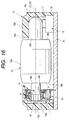
- the first operating member 18 tilts at a predetermined angle A1 on its third shaft 18d side with the first rotary electric part D1 as fulcrum, as shown in Fig. 17, with the result that the push-button 17 moves downward and the push-switch 15 is operated (contact ON to OFF or OFF to ON).
- the third shaft 18d is guided by a vertical groove (not shown) formed in the case 19 and thus its downward movement can be done accurately.
- the second operating member 18 when operated for rotation, it rotates while being supported by both the second rotary electric part D2 and the partition wall 19d. Its rotating motion is the same as in the case of the first operating member 18 described previously, so an explanation thereof will here be omitted.
- the input device of this embodiment is operated in this manner.
- a vertical scrolling operation is performed by the first electric part D1 through the first operating member 18 and a decision operation is performed by the push-switch 15, while a transverse scrolling operation is performed by the second electric part D2 through the second operating member 18 and a decision operation is performed by the push-switch 15, thus permitting a multi-functional operation to be effected.
- the tilting motion of the rotor 8 is performed with the insulating base 1 as a support member
- the mounting plate 12 or another member may be used as the support member.
- the second operating member 18 does not perform a tilting motion
- a case 20 which is formed by molding a synthetic resin and which is in the shape of a rectangular parallelepiped, comprises a front wall 20a, side walls 20b extending from four sides of the front wall 20a, and a back wall 20c opposite to the front wall 20a.
- Various electric parts (not shown) are accommodated within the case 20, and a display 21 is provided in an upper position of the front wall 20a.
- the input device of the above second embodiment is disposed within the case 20 at a position close to the display 21 and the operating portions 18a of the first and second operating members 18 are partially exposed from a hole (not shown) formed in the case 20.
- Plural push-buttons are disposed on the front wall 20a of the case 20 at positions below the input device.
- the case 19 may be substituted by the case 20.
- the input device of the above second embodiment is used in the portable electronic device, it may be substituted by the input device of the above first embodiment.
- the portable electronic device having such a configuration is operated in the same way as in the input device of the above second embodiment, which operation is performed while checking display contents on the display 21.
Abstract
Description
- The present invention relates to an input device for use in a portable electronic device such as a portable telephone set, as well as a portable electronic device using the input device.
- The configuration of a conventional input device will now be described with reference to Fig. 20. A rotary
electric part 50 is constituted by a rotary encoder, and aninsulating base 51 formed by molding a synthetic resin and constituting the rotaryelectric part 50, is provided with asubstrate portion 51b having a centralcircular hole 51a, withplural contact pieces 52 being embedded in thesubstrate portion 51b. - A
cover 53 of the rotaryelectric part 50 is provided with acylindrical portion 53b having acircular hole 53a. Thecover 53 is attached to theinsulating base 51 so as to cover an opening portion of the insulating base. - A
rotor 54 of the rotaryelectric part 50, which rotor is formed by molding a synthetic resin, is provided with adisc portion 54a,shaft portions disc portion 54a, and a hexagonal, non-circular throughhole 54d formed in a central part of therotor 54.Code patterns 55 are formed on a surface of thedisc portion 54a. - In the
rotor 54 constructed as above, theshaft portion 54b is fitted in thehole 51a of theinsulating base 51 and theshaft portion 54c is fitted in thehole 53a of thecylindrical portion 53b. Further, therotor 54 is sandwiched axially and rotatably between theinsulating base 51 and thecover 53. - By both
insulating base 51 andcover 53 therotor 54 is held so as not to tilt in the axial direction. - When the
rotor 54 is mounted, thecode patterns 55 formed on the rotor come into contact with thecontact pieces 52, and upon rotation of therotor 54, thecode patterns 55 also rotate in sliding contact with thecontact pieces 52 and produce pulse signals. The rotaryelectric part 50 thus constructed is mounted to a printed circuit board P2. - The conventional input device has a push-
switch 56. The push-switch 56 is provided with ahousing 56a formed by molding a synthetic resin and with a contact portion (not shown) housed therein and is also provided with a push-button 56b attached to thehousing 56a movably. The push-switch 56 is mounted to the printed circuit board P2 in a predetermined spaced position from the rotaryelectric part 50. - An
operating member 57 is provided with anoperating portion 57a of a large diameter,shafts operating portion 57a, and a regularhexagonal sphere portion 57d formed at one end of theshaft 57b. - The
operating member 57 is mounted by inserting the regularhexagonal sphere portion 57d on theshaft 57b side into thethrough hole 54a of therotor 54 from theinsulating base 51 side and by holding theshaft 57c with thehousing 56a. A coiledspring 58 is disposed between theshaft 57c and thehousing 56a so that theoperating member 57 is positioned on a horizontal line Z2. - According to this arrangement, the
operating member 57 can perform both a rotating motion and a tilting motion with the abutment portion of the regularhexagonal sphere portion 57d against therotor 54 as fulcrum. - In the conventional input device having such a configuration, when the
operating portion 57a of theoperating member 57 is rotated, therotor 54 is rotated by the regularhexagonal sphere portion 57d of theshaft 57b and thecode patterns 55 rotate in sliding contact with thecontact pieces 52, producing pulse signals. - If the
operating member 57 is pushed in a direction perpendicular to the axial direction (i.e., horizontal line Z2), theshaft 57c moves against the coiledspring 58 with the abutment portion of the regularhexagonal sphere portion 57d against therotor 54 as fulcrum, theoperating member 57 tilts to the position indicated with an inclined line Y2, and the push-button 56b is pushed by theshaft 57c to operate the push-switch 56. - Upon release of the
operating member 57, the operating member returns to its original position on the horizontal line Z2 under the action of the coiledspring 58 and the push-switch 56 also reverts to its original state. - In the case where the conventional input device, which is operated in such a manner, is used in a portable electronic device for example, a vertical or transverse scrolling operation is performed by the rotary
electric part 51, and an operation for decision is performed by the push-switch. - In the conventional input device, since one rotary
electric part 51 and the push-switch 56 are operated by oneoperating member 57, the number of functions available is small and thus the conventional input device is unsuitable for a portable electronic device for which various functions are required and is not convenient for use. - When the
operating member 57 tilts in the conventional input device, the regularhexagonal sphere portion 57d performs a circular motion with respect to therotor 54, and for allowing the circular motion to be carried out smoothly, the regularhexagonal sphere portion 57d is fitted in the throughhole 54d loosely. Consequently, between the regularhexagonal sphere portion 57d and therotor 54 there occurs a play in the rotational direction upon rotation of theoperating member 57, so that the rotation of theoperating member 57 cannot immediately be transmitted to therotor 54. - Further, as the tilting motion of the
operating member 57 is repeated, there occurs wear between the regularhexagonal sphere portion 57d and therotor 54, so that the play in the rotational direction becomes larger, making it more and more distant from the possibility of immediate transfer of the rotation of theoperating member 57 to therotor 54. - Accordingly, it is an object of the present invention to provide a small-sized, input device which is suitable for a portable electronic device required to have various functions and which is convenient for use, as well as a portable electronic device using the input device.
- According to the first solving means adopted by the invention for solving the above-mentioned problems there is provided an input device comprising a first operating member for operating a first rotary electric part, the first operating member being rotatable, and a second operating member for operating a second rotary electric part, the second operating member being also rotatable, the first and second operating members being each provided, on an outer peripheral portion in an axial direction thereof, with an operating portion for performing an operation in a direction orthogonal to the axial direction, the first and second operating members being disposed so as to be positioned close to each other in one and the same plane and so that the respective axial directions are orthogonal to each other.
- Preferably, the first and second operating members are arranged in T shape so that the axial direction of the second operating member intersects the axial direction of the first operating member at an intermediate position in the axial direction of the operating portion of the first operating member.
- Alternatively, the first and second operating members are arranged in L shape.
- Preferably, there is provided an input device wherein a knurled portion is formed on a surface of each of the operating portions, the knurled portion being formed by a concave-convex portion in the axial direction of the associated operating member.
- Preferably, one of the first and second operating members can tilt with the associated first or second rotary electric part as fulcrum when pushed in a direction perpendicular to the axial direction thereof, and a push-switch is operated by the tilting motion.
- Preferably, both the first and second operating members can tilt with the first and second rotary electric parts as fulcrums when pushed in directions perpendicular to the respective axial directions, and a push-switch is operated by the tilting motion of each of the first and second operating members.
- According to another aspect of the present invention there is provided a portable electronic device comprising a case having a display in a front wall thereof, a first operating member for operating a first rotary electric part disposed within the case, the first operating member being rotatable, and a second operating member for operating a second rotary electric part disposed within the case, the second operating member being also rotatable, the first and second operating members being each provided, on an outer peripheral portion in an axial direction thereof, with an operating portion for performing an operation in a direction orthogonal to the axial direction, the first and second operating members being disposed so as to be positioned close to each other in one and the same plane, allowing the respective operating portions to be partially exposed from the front wall of the case, and so that the respective axial directions are orthogonal to each other.
- Preferably, the first and second operating members are positioned close to the display.
- Preferably, the first and second operating members are arranged in T shape.
- Alternatively, the first and second operating members are arranged in L shape.
- Preferably, a knurled portion is formed on a surface of each of the operating portions, the knurled portion being formed by a concave-convex portion in the axial direction of the associated operating member.
- Preferably, one of the first and second operating members can tilt with the rotary electric part as fulcrum when pushed in a direction perpendicular to the axial direction thereof, and a push-switch is operated by the tilting motion.
- Preferably, both the first and second operating members can tilt with the rotary electric part as fulcrum when pushed in directions perpendicular to the respective axial directions, and a push-switch is operated by the tilting motion.
- According to another aspect of the present invention there is provided an input device comprising a first rotary electric part having a rotor, a first operating member for operating the first rotary electric part, the first operating member having a first shaft fitted in a non-circular hole formed in the rotor of the first rotary electric part, a second rotary electric part having a rotor, and a second operating member for operating the second rotary electric part, the second operating member having a second shaft fitted in a non-circular hole formed in the rotor of the second rotary electric part, the first and second operating members being positioned in alignment with each other.
- Preferably, the first operating member is further provided with an operating portion and a third shaft, and the second operating member is further provided with an operating portion and a fourth shaft, the third and fourth shafts being located respectively on the sides opposite to the first and second shafts with respect to the operating portions and in proximity to each other.
- Preferably, one push-switch is disposed below the third and fourth shafts so as to straddle both shafts, the first or the second operating member tilts when pushed in a direction perpendicular to its axial direction, and the push-switch is operated thereby.
- According to a further aspect of the present invention there is provided a portable electronic device having an input device, the input device comprising a first rotary electric part having a rotor, a first operating member for operating the first rotary electric part, the first operating member having a first shaft fitted in a non-circular hole formed in the rotor of the first rotary electric part, a second rotary electric part having a rotor, and a second operating member for operating the second rotary electric part, the second operating member having a second shaft fitted in a non-circular hole formed in the rotor of the second rotary electric part, the first and second operating members being positioned in alignment with each other.
- An embodiment of the present invention will now be described by way of example only, with reference to the accompanying diagrammatic drawings, in which:
- Fig. 1 is a sectional view of a principal portion of an input device according to the first embodiment of the present invention;
- Fig. 2 is an enlarged sectional view of a principal portion, illustrating the operation of the input device shown in Fig. 1;
- Fig. 3 is a front view of an encoder used in the input device;
- Fig. 4 is a rear view of the encoder shown in Fig. 3;
- Fig. 5 is a top view of the encoder shown in Fig. 3;
- Fig. 6 is a bottom view of the encoder shown in Fig. 3:
- Fig. 7 is an exploded perspective view of the encoder shown in Fig. 3;
- Fig. 8 is a sectional side view of a principal portion of the encoder shown in Fig. 3;
- Fig. 9 is a sectional front view of a principal portion of the encoder shown in Fig. 3;
- Fig. 10 is a perspective view showing a combination of an insulating base and a rotor in the encoder illustrated in Fig. 3;
- Fig. 11 is a sectional view of a rotor used in the encoder shown in Fig. 3;
- Fig. 12 is a perspective view of the encoder shown in Fig. 3;
- Fig. 13 is a side view of the encoder shown in Fig. 3;
- Fig. 14 is a sectional view of the encoder shown in Fig. 3;
- Fig. 15 is a sectional plan view of a principal portion of an input device according to the second embodiment of the present invention;
- Fig. 16 is a sectional view taken on line 16-16 in Fig. 15;
- Fig. 17 is a sectional view showing the operation of the input device illustrated in Fig. 15;
- Fig. 18 is a partially cut-away plan view of a portable electronic device according to the present invention;
- Fig. 19 is a side view of the portable electronic device shown in Fig. 18; and
- Fig. 20 is a partially sectional front view of a conventional input device.
-
- With reference to Figs. 3 to 14, a description will first be given about the configuration of a rotary electric part D used in an input device and a portable electronic device both embodying the present invention. The rotary electric part D used in this embodiment is formed as a rotary encoder. An
insulating base 1, which is formed by molding an insulating material, is made up of a rectangularmain base portion 2, aside wall portion 3 which is upright at right angles from themain base portion 2, and a pair ofsub-base portions 5 connected respectively both sides of themain base portion 2 through thin-walled portions 4. - The
main base portion 2 is provided withrecesses 2a formed respectively in end faces on both sides, acylindrical protrusion 2b formed centrally on a front end face, and a pair of retainingportions 2c formed on a lower surface of the main base portion and each having a tapered portion. - The
side wall portion 3 is formed upright from corners of an upper surface of themain base portion 2. Theside wall portion 3 is provided with a centralcircular hole 3b having aflange 3a, a pair ofrelief holes 3c extending from both sides of thehole 3b up to themain base portion 2, a pair ofupper walls 3d extending perpendicularly from an upper position, agroove 3e formed between the pairedupper walls 3d, retainingportions 3f formed respectively on upper surfaces of the pairedupper walls 3d, andprotrusions 3g. - Each of the paired
sub-base portions 5 is provided with aconvex portion 5a formed on an end face and having a roundish end. - By bending the thin-
walled portions 4 in the state shown in Fig. 7 and by press-fitting theprotrusions 5a of thesub-base portions 5 into therecesses 2a of themain base portion 2 there is formed a rectangular insulatingbase 1, as shown in Fig. 10. - A plurality of
contact pieces 6 each formed by a metallic plate are each provided with acontact portion 6a and aterminal portion 6b. Thecontact pieces 6 are respectively embedded in thesub-base portions 5. Thecontact portion 6a projects upward from an upper surface of the insulatingbase 1, while theterminal portion 6b projects downward from a lower surface of the insulatingbase 1 and a flat surface of an outer end thereof is bent so as to be positioned in parallel with and at substantially the same position as one end of the insulatingbase 1, i.e., theside wall portion 3. - A
common contact piece 7, which is formed of a metal, is provided with a pair ofcontact portions 7a and aterminal portion 7b. Thecommon contact piece 7 is embedded in themain base portion 2 at a position close to theside wall portion 3. Thecontact portions 7a project upward from the upper surface of the insulatingbase 1 and are positioned in the relief holes 3c of theside wall portion 3, while theterminal portion 7b projects downward from the lower surface of the insulatingbase 1. - In this embodiment, part of each embedded
contact piece 6 straddles themain base portion 2 and the associatedsub-base portion 5 and constitutes each thin-walled portion 4 as a connection between the main andsub-base portions - A metallic plate separate from that of the
contact piece 6 may be embedded in the insulatingbase 1 to form each thin-walled portion 4. Further, the thin-walled portion 4 may be formed by the insulating material of the insulatingbase 1. - A
cylindrical rotor 8, which is formed by molding an insulating material, comprises ashaft portion 8a provided on one end side, a holdingportion 8b formed contiguously to theshaft portion 8a and having a diameter larger than the diameter of theshaft portion 8a, a concave-convex portion 8d for clicking which is formed on anend face 8c on one side of the holdingportion 8b which end face is orthogonal to a rotational axis direction of the rotor, and endface 8e positioned between theshaft portion 8a and the holdingportion 8b on an opposite side of the holding portion, theend face 8e being orthogonal to the rotational axis direction of the rotor, and a non-circular,hexagonal hole 8f formed centrally. - A
code member 9, which is formed by a metallic plate, is provided with a ring-like plate portion 9a which forms a common pattern and a plurality oftongue pieces 9b which are bent from an inner periphery of theplate portion 9a and which form code patterns, as shown particularly in Fig. 11. - The
code member 9 is embedded or press-fitted into therotor 8. The ring-like plate portion 9a which forms a common pattern is positioned at theend face 8e of therotor 8, while thetongue pieces 9b which form a code pattern are exposed to an outer circumferential surface of the holdingportion 8b. Thetongue pieces 9b extend in an axial direction G1 of therotor 8. - The shaft portion of the
rotor 8 is inserted into thehole 3b of theside wall portion 3, whereby therotor 8 and thecode member 9 both constituted as above are held rotatably. - In this case, as shown in Fig. 14, the
shaft portion 8a is fitted in thehole 3b loosely so as to create a small clearance K1, thereby permitting therotor 8 to perform a tilting motion with respect to the insulatingbase 1. - When the
rotor 8 is mounted to the insulatingbase 1, the pairedcontact portions 7a of thecommon contact piece 7 are opposed to theend face 8e and are in contact with theplate portion 9a as a common pattern of thecode member 9. - With the
rotor 8 mounted to the insulatingbase 1, theplural contact pieces 6 are positioned on opposite sides with the circumferential surface of the rotor therebetween and come into and out of contact with thetongue pieces 9b as code patterns of thecode member 9, and a pair ofcontact portions 6a are brought into contact with the code patterns with a phase difference. - At this time, as shown in Fig. 8, the
contact pieces 6 are located perpendicularly to the axial direction G1 and are put in sliding contact with the code patterns. - An engaging
member 10, which is formed by a metallic plate, comprises a rectangular plate-like base portion 10a, an engagingportion 10b formed by cutting and bending a central part of thebase portion 10 in a C shape, the engagingportion 10b having convex portions at free ends thereof, acircular hole 10c formed in a lower position of thebase portion 10a, a pair ofside plates 10d bent from both sides of thebase portion 10a, cut and raisedportions 10e formed in theside plates 10d respectively, a T-shaped upper-side plate 10g bent from an upper side of thebase portion 10a and having a retainingportion 10f at a free end thereof, and a C-shaped lower-side plate 10j bent from a lower side of thebase portion 10a and having arectangular hole 10h formed centrally. - The engaging
member 10 is aligned with the insulatingbase 1 so that the engagingportion 10b becomes opposed to theend face 8c of therotor 8 having the concave-convex portion 8d, and then theprotrusion 2b is inserted into thehole 10c. - Thereafter, the upper-
side plate 10g is positioned on theupper walls 3d of theside wall portion 3 and is pushed in, allowing the retainingportion 10f to be engaged with the retainingportions 3f. Further, the upper-side plate 10g is positioned in thegroove 3e and is secured to theside wall portion 3. - Simultaneously with the mounting of the upper-
side plate 10g the lower-side plate 10j is positioned on the lower surface of themain base portion 2 and is pushed in, allowing the retainingportions 2c to be positioned in thehole 10h, whereby the lower-side plate 10j is locked to the retainingportions 2c and the lower-side plate 10j is secured to themain base portion 2. - In this way the engaging
member 10 is mounted at both upper and lower positions relative to therotor 8, while theside plates 10d are located at right and left positions respectively relative to therotor 8. - When the engaging
member 10 is mounted, the convex portions of the engagingportion 10b are engaged disengageably with the concave-convex portion 8d formed on theend face 8c of therotor 8, constituting a click mechanism. - Further, the engaging
member 10, thecontact pieces 6 and thecommon contact piece 7 extend toward therotor 8 with the insulatingbase 1 as a reference plane. - An encoder body E1 is formed by such a configuration.
- As shown in Figs. 12 to 14, a mounting
plate 12, which is constituted by a solderable metallic plate, comprises aflat plate portion 12c, theflat plate portion 12c having acylindrical portion 12h formed with a largecircular hole 12a centrally and also having asmall hole 12b in a lower position, a pair ofarm portions 12d bent opposedly from both sides of theflat plate portion 12c,rectangular holes 12e formed centrally of thearm portions 12d respectively, mountingportions 12f bent from side ends of thearm portions 12d, and projectingportions 12g provided on the mountingportions 12f side of theflat plate portion 12c. - As shown in Figs. 12 to 14, the mounting
plate 12 is positioned on the engagingmember 10 side of the encoder body E1 and thecylindrical portion 12h is positioned within therotor 8, then in this state theprotrusion 2b of the insulatingbase 1 is inserted into thesmall hole 12b. - Thereafter, the arm portions are pushed inwards on the
side plates 10d of the engagingmember 10, so that the cut and raisedportions 10e are positioned in theholes 12e respectively and thearm portions 12d are engaged with the cut and raisedportions 10e, whereby the mountingplate 12 is snap-fastened to the engagingmember 10. - When the mounting
plate 12 is thus mounted, theflat plate portion 12c is superimposed outside the plate-like base portion 10a of the engagingmember 10, thearm portions 12d are mounted to theside plate 10d respectively at right and left positions with respect to the rotor 8.Lower surfaces of the mountingportions 12f bent from side ends of thearm portions 12d which extend in the axial direction G1 of therotor 8 are located at approximately the same position as the L-shapedterminal portions contact pieces 6 and thecommon contact piece 7 both extending from the lower surface of the insulatingbase 1. - When the mounting
plate 12 is mounted, as shown in Fig. 14, a clearance K2 is formed between thecylindrical portion 12h and therotor 8, the clearance K2 being larger than the clearance K1. - The
rotor 8 is brought into abutment against theside wall portion 3 by the engagingmember 10. - In this way there is formed a rotary encoder as the rotary electric part D. It goes without saying that the rotary encoder may be substituted by another rotary electric part.
- In the rotary electric part D with the mounting
plate 12 attached thereto, as shown in Fig. 13, the undersides of the main- andsub-base portions portions 12g are inserted intoholes 13 formed in the printed circuit board P1, whereby the rotary electric part D is established its position. At the same time, theterminal portions contact pieces 6 and thecommon contact piece 7, and the mountingportions 12f of the mountingplate 12, are positioned on wiring patterns (not shown) formed on an upper surface of the printed circuit board P1. - The
contact pieces 6, thecommon contact piece 7 and the mountingplate 12 thus constituted are surface-mounted to the wiring patterns by creamy solder and thus mounted to the printed circuit board P1, whereby the rotary electric part D is mounted to the printed circuit board in parallel with the axial direction G1 of therotor 8. - A description will now be given about the operation of the rotary encoder as the rotary electric part D constructed as above. First, an operating
member 18 to be described later is fitted and engaged into thehole 8f of therotor 8 through thehole 12a of the mountingplate 12 and is then rotated, so that therotor 8 and thecode member 9 rotate with theshaft portion 8a as a support portion. - The concave-
convex portion 8d of therotor 8 performs engaging and disengaging motions for the engagingportion 10b to effect a click motion, thetongue pieces 9b come into and out of contact with thecontact pieces 6, and thecommon contact piece 7 contacts theplate portion 9a constantly, with consequent generation of a two-phase pulse signal between thecontact pieces 6 and thecommon contact piece 7. - The following description is now provided about the first embodiment of the present invention. As shown in Fig. 1, first and second rotary electric parts D1, D2, as the rotary electric part D constituted as above, are mounted to the printed circuit board P1 spacedly in alignment with each other through mounting
plates 12 which are opposed to each other, as shown in Fig. 1. - As shown in Fig. 1, a push-
switch 15 is made up of ahousing 16 which houses a contact portion (not shown) therein and a push-button 17 which is secured to thehousing 16 vertically movably and which is urged upwards constantly. The push-switch 15 is mounted to the printed circuit board P1 at a position intermediate between the first and second rotary electric parts D1, D2 and on an extension of the axial direction G1. - First and
second operating members 18, which are formed by molding a synthetic resin, each comprise acylindrical operating portion 18a of a large diameter, a firstcylindrical shaft 18c and a thirdcylindrical shaft 18d (or a secondcylindrical shaft 18c and a fourthcylindrical shaft 18d) smaller in diameter than the operatingportion 18a, theshafts member 18 from central positions of both side faces 18b of the operatingportion 18a, and a hexagonal, non-cylindrical,non-circular portion 18e formed at an end portion of the first (or the second)shaft 18c. - The first and
second shafts 18c of the first andsecond operating members 18 are respectively inserted into theholes 12a from the mountingplates 12 side while being guided by thecylindrical portions 12h, and thenon-circular portions 18e are fitted respectively in thenon-circular holes 8f of therotors 8. - At this time, the
non-circular portions 18e and theholes 8f are fitted together tightly, leaving no play between the two in the rotational direction. - When the first and
second shafts 18c are inserted into theholes 8f,protuberances 18f project outwards from theholes 8f and the other third andfourth shafts 18d are close to each other and abutted against the top of the push-button 17. - In this state, the axial directions G1 and G2 of the
rotor 8 and the first andsecond operating members 18, respectively, are aligned with each other, as shown in Fig. 1. - As shown in Fig. 1, a
case 19, which is formed by molding a synthetic resin, comprises anupper wall 19b having twoparallel holes 19a, andside walls 19c extending downwards from the outer periphery of theupper wall 19b. - The
case 19 is affixed to the printed circuit board P1 while covering the first and second rotary electric parts D1, D2 and also covering the push-switch 15. When thecase 19 is thus mounted, part of the operatingportions 18a of the first andsecond operating members 18 projects outwards from theholes 19a, theprotuberances 18f are abutted against or close toside walls 19c, and the third andfourth shafts 18d are close to each other, to prevent the first andsecond operating members 18 from moving in the axial direction G2. - The third and
fourth shafts 18d of the first andsecond operating members 18 are positioned close to each other and are simultaneously supported by theupper wall 19b. - Reference will now be made to the operation of the input device of this embodiment which is constituted as described above.
- First, the operating
portion 18a of thefirst operating member 18 projecting from the associatedhole 19a is rotated with a finger, with consequent rotation of the first andthird shafts code member 9 together with therotor 8 through thenon-circular portion 18e, so that thecontact pieces 6 come into sliding contact with thetongue pieces 9b as code patterns, producing a pulse signal. - There is made pre-setting so that the pulse signal is OFF when the engaging
member 10 is engaged with a concave in the concave-convex portion 8d. - Next, if the operating
portion 18a of thefirst operating member 18 is pushed in a direction B orthogonal to the axial direction G2, the operatingmember 18 tilts at a predetermined angle A1 on itssecond shaft 18d side with the first rotary electric part D1 as fulcrum, as shown in Fig. 2, with the result that the push-button 17 moves downward and the push-switch 15 is operated (contact ON to OFF or OFF to ON). - More specifically, the tilting motion of the
first operating member 18 is performed in the following manner. As shown in Fig. 2, when the operatingmember 18 is pushed, first a lower portion of theshaft 8a of therotor 8 comes into abutment with the side face of the insulatingbase 1 which defines thehole 3b. As the operatingmember 18 is further pushed, therotor 8 begins to tilt with an abutment portion T1 as fulcrum and at the same time the outermost periphery of theplate portion 9a of thecode member 9 abuts the insulatingbase 1 at an abutment portion T2. With both abutment portions T2 and T1 of thecode member 9 and theshaft 8a, respectively, as fulcrums, therotor 8 tilts, and with this tilting motion of the rotor, the operatingmember 18 also tilts together with the rotor. - As a result, the
rotor 8 tilts at a predetermined angle A2 equal to that of the operatingmember 18 and the mounting plate 12-side portion of therotor 8 moves to a greater extent than the insulating base 1-side portion thereof, but the presence of the large clearance K2 permits the tilting motion of therotor 8. - Further, when the
rotor 8 tilts, the code patterns (tongue pieces 9b) extending in the axial direction G1 and thecontact pieces 6 disposed perpendicularly thereto are in contact with each other, provided the position of contact of the code patterns with thecontact pieces 6 merely shifts downward, and therefore both are kept contacted positively. - Besides, since the position of contact of the
contact pieces 6 with thetongue pieces 9b is close to the tilt center, the tongue pieces are less displaced at their contact portions with thecontact pieces 6, thus making it difficult to produce unnecessary pulse signals. - Next, when the pressure imposed on the
first operating member 18 is relieved, thethird shaft 18d is restored to its original state by the urged push-button 17, so that thefirst operating member 18 and therotor 8 are restored to their original horizontal state and the push-switch 15 also reverts to its original state. Thus, switching of contacts is performed. - During the tilting motion of the
first operating member 18, thethird shaft 18d is guided by a vertical groove (not shown) formed in thecase 19 and thus its downward movement can be done accurately. - The operation for rotation and tilting of the
second operating member 18 is the same as that for thefirst operating member 18 described above, so an explanation thereof will here be omitted. The input device of this embodiment is operated in the manner described above. - In the case where the input device of this embodiment is applied to a portable electronic device for example, a vertical scrolling operation is performed by the first electric device D1 through the
first operating member 18 and a decision operation is performed by the push-switch 15, while a transverse scrolling operation is performed by the second electric part D2 through thesecond operating member 18 and a decision operation is performed by the push-switch 15. Thus, a multi-functional operation can be effected. - Moreover, since the first and
second operating members 18 are aligned with each other, the above operations can be done by putting one finger of one hand on the first operating member and putting another finger on the second operating member and then moving the fingers. - Although in the above embodiment the tilting motion of the
rotor 8 is conducted with the insulatingbase 1 as a support member, the mountingplate 12 or another member may be used as the support member. - Description is now directed to an input device according to the second embodiment of the present invention and a portable electronic device using the input device.
- As to a rotary electric part D used in this embodiment, it is of the same configuration as that described above and so an explanation thereof will here be omitted, and the same components as in the input device of the previous first embodiment will be identified by the same reference numerals as in the first embodiment.
- In the input device of this second embodiment, as shown in Fig. 15, first and second rotary electric parts D1, D2, as the rotary electric part D constituted as above, are mounted to a printed circuit board P1 in a state such that the respective axial directions G1 are orthogonal to each other.
- As shown in Figs. 15 to 18, a push-
switch 15 is made up of ahousing 16 which houses a contact portion (not shown) therein and a push-button 17 which is secured to thehousing 16 vertically movably and which is urged upwards constantly. The push-switch 15 is mounted to the printed circuit board P1 on an extension of the axial direction G1 of the first rotary electric part D1. - First and
second operating members 18, which are formed by molding a synthetic resin, each comprise acylindrical operating portion 18a of a large diameter, a firstcylindrical shaft 18c and a thirdcylindrical shaft 18d (or a secondcylindrical shaft 18c and a fourthcylindrical shaft 18d) smaller in diameter than the operatingportion 18a, theshafts member 18 from central positions of both side faces 18b of the operatingportion 18a, a hexagonal, non-cylindrical,non-circular portion 18e formed at an end portion of the first (or the second)shaft 18c, and aknurled portion 18g formed on the surface of the operatingportion 18a. - Although in this embodiment the
knurled portion 18g is formed by a concave-convex portion in the axial direction G2, it may be a knurled portion other than such concave-convex portion. For example, it may be a rough surface. - The first and
second shafts 18c of the first andsecond operating members 18 are respectively inserted intoholes 12a from a side of mountingplates 12 of the first and second rotary electric parts D1 and D2 while being guided bycylindrical portions 12h, and thenon-circular portions 18e are fitted respectively in thenon-circular holes 8f of therotors 8. - At this time, the
non-circular portions 18e and theholes 8f are fitted together tightly, leaving no play between the two in the rotational direction. - When the first and
second shafts 18c are inserted into theholes 8f,protuberances 18f project outwards from theholes 8f and the other third andfourth shafts 18d are abutted against the top of the push-button 17. - In this state, the axial direction G1 of the rotor of the first rotary electric part D1 and the axial direction G2 of the
first operating member 18 are aligned with each other and so are the axial direction G1 of therotor 8 of the second rotary electric part D2 and the axial direction G2 of thesecond operating member 18, as shown in Fig. 15. Further, the first andsecond operating members 18 are positioned close to each other in one and the same plane in such a manner that the respective axial directions G2 are orthogonal to each other. - In this embodiment, the first and
second operating members 18 are disposed in T shape so that the axial direction G2 of thesecond operating member 18 is located at an intermediate position in the axial direction G2 of the operatingportion 18a of thefirst operating member 18. - The
second operating member 18 may be shifted in the axial direction G2 from an intermediate portion of thefirst operating member 18 so that the first andsecond operating members 18 are arranged in L shape. - As shown in Figs. 15 to 17, a
case 19, which is formed by molding a synthetic resin, comprises anupper wall 19b having twoholes 19a formed in side positions of the T shape,side walls 19c extending downwards from the outer periphery of theupper wall 19b, and apartition wall 19d. - The
case 19 is affixed to the printed circuit board P1 while covering the first and second rotary electric parts D1, D2 and also covering the push-switch 15. When thecase 19 is thus mounted, part of the operatingportions 18a of the first andsecond operating members 18 projects outwards from theholes 19a, theprotuberances 18f are abutted against or close toside walls 19c, thethird shaft 18d of thefirst operating member 18 is close to aside wall 19c, and thefourth shaft 18d of thesecond operating member 18 is fitted in ahole 19e formed in thepartition wall 19d to prevent the first andsecond operating members 18 from moving in the axial direction G2. - At the same time, the
third shaft 18d of thefirst operating member 18 is supported by theupper wall 19b. - Next, the operation of the input device of the second embodiment having the above configuration is described.
- First, the operating
portion 18a of thefirst operating member 18 projected from the associatedhole 19a is rotated with a finger in a direction orthogonal to the axial direction G2, with consequent rotation of the first andsecond shafts code member 9 together with the associatedrotor 8 via thenon-circular portion 18e, so thatcontact pieces 6 come into sliding contact withtongue pieces 9b as code patterns, producing a pulse signal. - There is made pre-setting so that the pulse signal is OFF when the engaging
member 10 is engaged with a concave in a concave-convex portion 8d. - Next, if the operating
portion 18a of thefirst operating member 18 is pushed in a direction perpendicular to the axial direction G2, thefirst operating member 18 tilts at a predetermined angle A1 on itsthird shaft 18d side with the first rotary electric part D1 as fulcrum, as shown in Fig. 17, with the result that the push-button 17 moves downward and the push-switch 15 is operated (contact ON to OFF or OFF to ON). - Detailed operations are the same as in the previous first embodiment.
- Next, when the pressure exerted on the
first operating member 18 is relieved, thethird shaft 18d is restored to its original state by the urged push-button 17, so that thefirst operating member 18 and therotor 8 are restored to their original horizontal state and the push-switch 15 also reverts to its original state. In this way there is made switching of contacts. - During the tilting motion of the
first operating member 18, thethird shaft 18d is guided by a vertical groove (not shown) formed in thecase 19 and thus its downward movement can be done accurately. - Next, when the
second operating member 18 is operated for rotation, it rotates while being supported by both the second rotary electric part D2 and thepartition wall 19d. Its rotating motion is the same as in the case of thefirst operating member 18 described previously, so an explanation thereof will here be omitted. The input device of this embodiment is operated in this manner. - Where the input device of this second embodiment is applied to a portable electronic device for example, a vertical scrolling operation is performed by the first electric part D1 through the
first operating member 18 and a decision operation is performed by the push-switch 15, while a transverse scrolling operation is performed by the second electric part D2 through thesecond operating member 18 and a decision operation is performed by the push-switch 15, thus permitting a multi-functional operation to be effected. - Besides, since the first and
second operating members 18 are disposed perpendicularly to each other, the above operations can be carried out by putting a finger on thefirst operating member 18, operating the first operating member with the finger, and then shifting the finger, allowing the finger to be positioned on thesecond operating member 18. Thus, thesecond operating member 18 can be continuously operated subsequent to the first operating member, whereby the input device is superior in operability. - Although in the above second embodiment the tilting motion of the
rotor 8 is performed with the insulatingbase 1 as a support member, the mountingplate 12 or another member may be used as the support member. - Although in the above second embodiment the
second operating member 18 does not perform a tilting motion, there may be adopted, as is the case with thefirst operating member 18, a modification wherein another push-switch is disposed below thefourth shaft 18d of thesecond operating member 18 and is pushed with a tilting motion of the second operating member. - Next, the configuration of the portable electronic device according to the present invention will be described with reference to Figs. 18 and 19. A
case 20, which is formed by molding a synthetic resin and which is in the shape of a rectangular parallelepiped, comprises afront wall 20a,side walls 20b extending from four sides of thefront wall 20a, and aback wall 20c opposite to thefront wall 20a. Various electric parts (not shown) are accommodated within thecase 20, and adisplay 21 is provided in an upper position of thefront wall 20a. - The input device of the above second embodiment is disposed within the
case 20 at a position close to thedisplay 21 and the operatingportions 18a of the first andsecond operating members 18 are partially exposed from a hole (not shown) formed in thecase 20. - Plural push-buttons, though not shown, are disposed on the
front wall 20a of thecase 20 at positions below the input device. - In the portable electronic device, the
case 19 may be substituted by thecase 20. Although the input device of the above second embodiment is used in the portable electronic device, it may be substituted by the input device of the above first embodiment. - The portable electronic device having such a configuration is operated in the same way as in the input device of the above second embodiment, which operation is performed while checking display contents on the
display 21. - Since the first and second rotary electric parts D1, D2 are operated by the first and
second operating members 18 respectively, a larger number of functions than in the prior art can be provided and therefore the input device according to the present invention is suitable for use in a portable electronic device for which various functions are required. - Moreover, the operating
portions 18a for performing motions in directions orthogonal to the axial directions G2 of the first andsecond operating members 18 are provided on the outer peripheral portions in the axial directions G2 of the operating members respectively, and the first andsecond operating members 18 are positioned close to each other in one and the same plane so that the respective axial directions G2 are orthogonal to each other. Consequently, it is possible to attain the reduction of size, and if a finger is put on thefirst operating member 18 and is shifted after operating the first operating member, the finger comes to be positioned on the second operating member, permitting thesecond operating member 18 to be operated in a continuous manner. Thus, the input device according to the present invention is superior in operability and convenient for use. - Since the first and
second operating members 18 are disposed in T shape and the axial direction G2 of thesecond operating member 18 lies at an intermediate position in the axial direction G2 of the operatingportion 18a of thefirst operating member 18, the input device according to the present invention is nice-looking and is superior in operability because thesecond operating member 18 can be operated by merely shifting a finger slightly from thefirst operating member 18. - Further, since the first and
second operating members 18 are disposed in L shape, thesecond operating member 18 can be operated by merely shifting a finger from thefirst operating member 18 to the second and thus input device according to the present invention is superior in operability. - Since the
knurled portion 18g is formed on the surface of the operatingportion 18a and is formed by a concave-convex portion in the axial direction G2 of each operatingmember 18, slipping is difficult to occur when operating the operatingportion 18a. Besides, since the concave-convex portions formed on both operatingportions 18a are orthogonal to each other, the operation of theother operating portion 18a is difficult to be done during the operation of oneoperating portion 18a. The input device according to the present invention is thus superior in operability. - Further, one of the first and
second operating members 18 can tilt with the associated rotary electric part as fulcrum when pushed in a direction orthogonal to the axial direction G2 thereof. With this tilting motion, the push-switch 15 is operated; that is, the rotating operation can be followed by operation of the push-switch 15 in a continuous manner. The input device according to the present invention is thus superior in operability. - Further, both first and
second operating members 18 can tilt with the rotary electric parts as fulcrums when pushed in directions orthogonal to the respective axial directions G2, and the push-switch 15 is operated with their tilting motions. Thus, the first and second operating members can operate the push-switch 15 continuously following their rotating motions. The input device according to the present invention is thus superior in operability. - Further, the portable electric device according to the present indention comprises the
case 20 having thedisplay 20a in thefront wall 20a, thefirst operating member 18 for operating the first rotary electric part D1 disposed within thecase 20, thefirst operating member 18 being rotatable, and thesecond operating member 18 for operating the second rotary electric part D2 disposed within thecase 20, thesecond operating member 18 being also rotatable, the first andsecond operating members 18 being each provided on the outer periphery in the axial direction G2 thereof with the operatingportion 18a for performing an operation in a direction orthogonal to the axial direction G2, the first andsecond operating members 18 being disposed so as to be positioned close to each other in one and the same plane, allowing therespective operating portions 18a to be partially exposed from thefront wall 20a of thecase 20, and so that the respective axial directions G2 are orthogonal to each other. According to this configuration, it is possible to increase the number of functions available and attain the reduction of size. Besides, if a finger is put on thefirst operating member 18 and is shifted after operating thefirst operating member 18, it comes to be positioned on thesecond operating member 18 and thus the second operating member can be operated in a continuous manner following the operation of the first operating member. The portable electronic device according to the present invention is thus superior in operability and convenient for use. - Since the operating
portions 18a are positioned close to thedisplay 21, it is easy to effect operation while looking the display. Thus, the portable electronic device according to the present invention is superior in operability. - Further, since the first and
second operating members 18 are arranged in T shape, thesecond operating member 18 can be operated by merely shifting a finger from thefirst operating member 18. Thus, the portable electronic device according to the present invention is superior in operability and convenient for use. - Further, since the first and
second operating members 18 are arranged in L shape, thesecond operating member 18 can be operated by merely shifting a finger from thefirst operating member 18 to the second and thus the portable electronic device according to the present invention is superior in operability. - Since the
knurled portion 18g is formed on the surface of the operatingportion 18a and is formed by a concave-convex portion in the axial direction G2 of each operatingmember 18, slipping is difficult to occur when operating the operatingportion 18a. Besides, since the concave-convex portions formed on both operatingportions 18a are orthogonal to each other, the operation of theother operating portion 18a is difficult to be done during the operation of oneoperating portion 18a. Thus, the portable electronic device according to the present invention is further improved in operability. - Further, one of the first and
second operating members 18 can tilt with the associated rotary electric part as fulcrum when pushed in a direction orthogonal to the axial direction G2 thereof. With this tilting motion, the push-switch 15 is operated; that is, the rotating operation can be followed by operation of the push-switch 15 in a continuous manner. The portable electronic device according to the present invention is thus superior in operability. - Further, both first and
second operating members 18 can tilt with the rotary electric parts as fulcrums when pushed in directions orthogonal to the respective axial directions G2, and the push-switch 15 is operated with the tilting motion of the first or thesecond operating member 18. Thus, the first and second operating members can operate the push-switch 15 continuously following their rotating motions. The portable electronic device according to the present invention is thus superior in operability. - Since the first and second rotary electric parts D1, D2 are operated by the first and
second operating members 18 respectively, a larger number of functions than in the prior art can be provided and therefore the input device according to the present invention is suitable for use in a portable electronic device for which various functions are required. - Since the first and
second operating members 18 are positioned in alignment with each other, both can be operated respectively with a finger of one hand put on the first operating member and another finger put on the second operating member. Thus, the input device according to the present invention is superior in operability and convenient for use. - Further, the first and
second operating members 18 are respectively provided withoperating portions 18a, first andsecond shafts 18c, and third andfourth shafts 18d located on the sides opposite to the first andsecond shafts 18c with respect to theoperating portions 18a, the third andfourth shafts 18d being positioned close to each other. Thus, the first andsecond operating members 18 can be positioned close to each other, that is, the operability is improved; besides, it becomes easier for the input device to be supported by thecase 19 and there can be attained the reduction of size and simplification of configuration. - Further, one push-
switch 15 is disposed below the third andfourth shafts 18d so as to straddle both shafts, and when the first or thesecond operating member 18 tilts when pushed in a direction orthogonal to the axial direction thereof, the push-switch 15 is operated thereby. Thus, the push-switch 15 can be used in common to two operatingmembers 18 and therefore the input device according to the present invention can be reduced in both size and cost. - Further, in the input device used in the portable electronic device according to the present invention, the first and second rotary electric parts D1, D2 are operated by the first and
second operating members 18 which are disposed in alignment with each other. Therefore, the portable electronic device is simple in operation and can utilize various functions.
Claims (17)
- An input device comprising:a first operating member for operating a first rotary electric part, the first operating member being rotatable; anda second operating member for operating a second rotary electric part, the second operating member being rotatable,the first and second operating members being each provided, on an outer peripheral portion in an axial direction thereof, with an operating portion for performing an operation in a direction orthogonal to the axial direction, the first and second operating members being disposed so as to be positioned close to each other in one and the same plane and so that the respective axial directions are orthogonal to each other.
- An input device according to claim 1, wherein the first and second operating members are arranged in T shape so that the axial direction of the second operating member intersects the axial direction of the first operating member at an intermediate position in the axial direction of the operating portion of the first operating member.
- An input device according to claim 1, wherein the first and second operating members are arranged in L shape.
- An input device according to claim 1, 2 or 3, wherein a knurled portion is formed on a surface of each of the operating portions, the knurled portion being formed by a concave-convex portion in the axial direction of the associated operating member.
- An input device according to any of claims 1 to 4 p wherein one of the first and second operating members can tilt with the associated first or second rotary electric part as fulcrum when pushed in a direction perpendicular to the axial direction thereof, and a push-switch is operated by the tilting motion.
- An input device according to any of claims 1 to 4, wherein both the first and second operating members can tilt with the first and second rotary electric parts as fulcrums when pushed in directions perpendicular to the respective axial directions, and a push-switch is operated by the tilting motion of each of the first and second operating members.
- A portable electronic device comprising:a case having a display in a front wall thereof;a first operating member for operating a first rotary electric part disposed within the case, the first operating member being rotatable; anda second operating member for operating a second rotary electric part disposed within the case, the second operating member being rotatable,the first and second operating members being each provided, on an outer peripheral portion in an axial direction thereof, with an operating portion for performing an operation in a direction orthogonal to the axial direction, the first and second operating members being disposed so as to be positioned close to each other in one and the same plane, allowing the respective operating portions to be partially exposed from the front wall of the case, and so that the respective axial directions are orthogonal to each other.
- A portable electronic device according to claim 7, wherein the operating portions of the first and second operating members are positioned close to the display.
- A portable electronic device according to claim 7 or 8, wherein the first and second operating members are arranged in T shape.
- A portable electronic device according to claim 7 or 8, wherein the first and second operating members are arranged in L shape.
- An portable electronic device according to any of claims 7 to 10, wherein a knurled portion is formed on a surface of each of the operating portions, the knurled portion being formed by a concave-convex portion in the axial direction of the associated operating member.
- A portable electronic device according to any of claims 7 to 11, wherein one of the first and second operating members can tilt with the associated first or second rotary electric part as fulcrum when pushed in a direction perpendicular to the axial direction thereof, and a push-switch is operated by the tilting motion.
- A portable electronic device according to any of claims 7 to 11, wherein both the first and second operating members can tilt with the first and second rotary electric parts as fulcrums when pushed in directions perpendicular to the respective axial directions, and a push-switch is operated by the tilting motion of each of the first and second operating members.
- An input device comprising:a first rotary electric part having a rotor;a first operating member for operating the first rotary electric part, the first operating member having a first shaft fitted in a non-circular hole formed in the rotor of the first rotary electric part;a second rotary electric part having a rotor; anda second operating member for operating the second rotary electric part, the second operating member having a second shaft fitted in a non-circular hole formed in the rotor of the second rotary electric part,the first and second operating members being positioned in alignment with each other.
- An input device according to claim 14, wherein the first operating member is further provided with an operating portion and a third shaft, and the second operating member is further provided with an operating portion and a fourth shaft, the third and fourth shafts being disposed in proximity to each other.
- An input device according to claim 15, wherein one push-switch is disposed below the third and fourth shafts so as to straddle both shafts, the first or the second operating member tilts when pushed in a direction perpendicular to its axial direction, and the push-switch is operated thereby.
- A portable electronic device having an input device, the input device comprising:a first rotary electric part having a rotor;a first operating member for operating the first rotary electric part, the first operating member having a first shaft fitted in a non-circular hole formed in the rotor of the first rotary electric part;a second rotary electric part having a rotor; anda second operating member for operating the second rotary electric part, the second operating member having a second shaft fitted in a non-circular hole formed in the rotor of the second rotary electric part, the first and second operating members being positioned in alignment with each other.
Applications Claiming Priority (4)
| Application Number | Priority Date | Filing Date | Title |
|---|---|---|---|
| JP2000072475A JP2001255990A (en) | 2000-03-10 | 2000-03-10 | Input device |
| JP2000072475 | 2000-03-10 | ||
| JP2000077823A JP2001265508A (en) | 2000-03-15 | 2000-03-15 | Input device and portable electronic equipment using the same |
| JP2000077823 | 2000-03-15 |
Publications (2)
| Publication Number | Publication Date |
|---|---|
| EP1132855A2 true EP1132855A2 (en) | 2001-09-12 |
| EP1132855A3 EP1132855A3 (en) | 2005-11-02 |
Family
ID=26587585
Family Applications (1)
| Application Number | Title | Priority Date | Filing Date |
|---|---|---|---|
| EP01301998A Withdrawn EP1132855A3 (en) | 2000-03-10 | 2001-03-05 | Input device and portable electronic device using the same |
Country Status (2)
| Country | Link |
|---|---|
| US (1) | US20010023179A1 (en) |
| EP (1) | EP1132855A3 (en) |
Cited By (2)
| Publication number | Priority date | Publication date | Assignee | Title |
|---|---|---|---|---|
| EP1574938A2 (en) | 2004-03-10 | 2005-09-14 | Samsung Electronics Co., Ltd. | A switch assembly |
| DE102009005283A1 (en) * | 2009-01-21 | 2010-07-22 | Leopold Kostal Gmbh & Co. Kg | Pressure- and rotationally actuated operating element i.e. steering wheel operating element, for motor vehicle, has mounting shaft or support element supported on towers, where support element is connected with shaft |
Citations (11)
| Publication number | Priority date | Publication date | Assignee | Title |
|---|---|---|---|---|
| DE8419546U1 (en) * | 1984-06-29 | 1984-10-31 | Stein, Norbert, 2000 Hamburg | Control device for the cursor on a computer screen |
| DE3906585A1 (en) * | 1989-03-02 | 1990-09-06 | Thomson Brandt Gmbh | Remote control unit |
| US5095303A (en) * | 1990-03-27 | 1992-03-10 | Apple Computer, Inc. | Six degree of freedom graphic object controller |
| JPH04220710A (en) * | 1990-12-21 | 1992-08-11 | Sharp Corp | Input device |
| EP0531829A1 (en) * | 1991-08-29 | 1993-03-17 | Alps Electric Co., Ltd. | Remote control device |
| DE19643201A1 (en) * | 1996-10-19 | 1998-04-23 | Loewe Opta Gmbh | Remote controller e.g. for consumer electronics |
| EP0845893A2 (en) * | 1996-11-29 | 1998-06-03 | Sony Corporation | Telephone data input device |
| EP0847069A1 (en) * | 1995-08-23 | 1998-06-10 | Matsushita Electric Industrial Co., Ltd. | Operation type electronic component |
| EP0901262A2 (en) * | 1997-09-04 | 1999-03-10 | Nokia Mobile Phones Ltd. | Menu navigation key for a portable telephone |
| GB2329695A (en) * | 1997-08-18 | 1999-03-31 | Cheng Kuo Shu | Computer mouse with additional input rollers |
| EP0946028A2 (en) * | 1998-03-25 | 1999-09-29 | Nokia Mobile Phones Ltd. | Context sensitive pop-up window for a portable phone |
Family Cites Families (7)
| Publication number | Priority date | Publication date | Assignee | Title |
|---|---|---|---|---|
| US5669485A (en) * | 1996-01-02 | 1997-09-23 | Motorola, Inc. | Rotary switch knob assembly with interspersed radial labeling |
| JP3437054B2 (en) * | 1997-05-12 | 2003-08-18 | アルプス電気株式会社 | Multi-input switch |
| KR20000047803A (en) * | 1998-12-04 | 2000-07-25 | 이데이 노부유끼 | Switch mechanism |
| TW508606B (en) * | 1999-07-27 | 2002-11-01 | Alps Electric Co Ltd | Multi-directional input device |
| DE60001480T2 (en) * | 1999-12-10 | 2003-08-28 | Alps Electric Co Ltd | angle encoder |
| JP3869996B2 (en) * | 2000-03-10 | 2007-01-17 | アルプス電気株式会社 | Multi-directional input device |
| JP2001312942A (en) * | 2000-04-27 | 2001-11-09 | Sony Corp | Communication terminal equipment and switching device |
-
2001
- 2001-03-05 EP EP01301998A patent/EP1132855A3/en not_active Withdrawn
- 2001-03-09 US US09/803,568 patent/US20010023179A1/en not_active Abandoned
Patent Citations (11)
| Publication number | Priority date | Publication date | Assignee | Title |
|---|---|---|---|---|
| DE8419546U1 (en) * | 1984-06-29 | 1984-10-31 | Stein, Norbert, 2000 Hamburg | Control device for the cursor on a computer screen |
| DE3906585A1 (en) * | 1989-03-02 | 1990-09-06 | Thomson Brandt Gmbh | Remote control unit |
| US5095303A (en) * | 1990-03-27 | 1992-03-10 | Apple Computer, Inc. | Six degree of freedom graphic object controller |
| JPH04220710A (en) * | 1990-12-21 | 1992-08-11 | Sharp Corp | Input device |
| EP0531829A1 (en) * | 1991-08-29 | 1993-03-17 | Alps Electric Co., Ltd. | Remote control device |
| EP0847069A1 (en) * | 1995-08-23 | 1998-06-10 | Matsushita Electric Industrial Co., Ltd. | Operation type electronic component |
| DE19643201A1 (en) * | 1996-10-19 | 1998-04-23 | Loewe Opta Gmbh | Remote controller e.g. for consumer electronics |
| EP0845893A2 (en) * | 1996-11-29 | 1998-06-03 | Sony Corporation | Telephone data input device |
| GB2329695A (en) * | 1997-08-18 | 1999-03-31 | Cheng Kuo Shu | Computer mouse with additional input rollers |
| EP0901262A2 (en) * | 1997-09-04 | 1999-03-10 | Nokia Mobile Phones Ltd. | Menu navigation key for a portable telephone |
| EP0946028A2 (en) * | 1998-03-25 | 1999-09-29 | Nokia Mobile Phones Ltd. | Context sensitive pop-up window for a portable phone |
Non-Patent Citations (1)
| Title |
|---|
| PATENT ABSTRACTS OF JAPAN vol. 016, no. 571 (P-1459), 11 December 1992 (1992-12-11) & JP 04 220710 A (SHARP CORP), 11 August 1992 (1992-08-11) * |
Cited By (3)
| Publication number | Priority date | Publication date | Assignee | Title |
|---|---|---|---|---|
| EP1574938A2 (en) | 2004-03-10 | 2005-09-14 | Samsung Electronics Co., Ltd. | A switch assembly |
| DE102009005283A1 (en) * | 2009-01-21 | 2010-07-22 | Leopold Kostal Gmbh & Co. Kg | Pressure- and rotationally actuated operating element i.e. steering wheel operating element, for motor vehicle, has mounting shaft or support element supported on towers, where support element is connected with shaft |
| DE102009005283B4 (en) * | 2009-01-21 | 2021-06-17 | Kostal Automobil Elektrik Gmbh & Co. Kg | Operating element for a motor vehicle that can be operated by pressing and rotating |
Also Published As
| Publication number | Publication date |
|---|---|
| US20010023179A1 (en) | 2001-09-20 |
| EP1132855A3 (en) | 2005-11-02 |
Similar Documents
| Publication | Publication Date | Title |
|---|---|---|
| JP4487821B2 (en) | Composite operation type electronic parts | |
| EP1139273B1 (en) | Multidirectional input device | |
| JP2001325859A (en) | Composite switching device | |
| WO2005038844A1 (en) | Rotating and pressing operation type electronic component and electronic device using the same | |
| JP3763711B2 (en) | Composite operation type electronic parts | |
| EP1132856A1 (en) | Input device and portable electronic device using same | |
| JP2002110002A (en) | Switch device | |
| EP1132855A2 (en) | Input device and portable electronic device using the same | |
| JP2005158328A (en) | Rotating operation type electronic parts | |
| JP4213019B2 (en) | Multi-directional input device | |
| JP2005259634A (en) | Rotary electrical component | |
| JP2001345031A (en) | Composite operating type electronic parts | |
| WO2005038843A1 (en) | Rotating and pressing operation type electronic component and electronic device using the same | |
| JP2001325860A (en) | Composite switching device | |
| JP3770768B2 (en) | Multi-directional input device | |
| JP3937670B2 (en) | Multi-directional operation switch | |
| EP0918344A2 (en) | Switch device and electronic devices using the switch device | |
| JP2001332155A (en) | Multi-directional input apparatus | |
| JP2001255990A (en) | Input device | |
| KR100298507B1 (en) | switch | |
| JP2001265508A (en) | Input device and portable electronic equipment using the same | |
| JP3819677B2 (en) | Input device | |
| JP3579960B2 (en) | Rotary operation type electronic component with push switch | |
| JP2024051281A (en) | Variable operating position microleaf switch and combined operation switch | |
| JP2004281275A (en) | Two-way operating switch |
Legal Events
| Date | Code | Title | Description |
|---|---|---|---|
| PUAI | Public reference made under article 153(3) epc to a published international application that has entered the european phase |
Free format text: ORIGINAL CODE: 0009012 |
|
| AK | Designated contracting states |
Kind code of ref document: A2 Designated state(s): AT BE CH CY DE DK ES FI FR GB GR IE IT LI LU MC NL PT SE TR |
|
| AX | Request for extension of the european patent |
Free format text: AL;LT;LV;MK;RO;SI |
|
| PUAL | Search report despatched |
Free format text: ORIGINAL CODE: 0009013 |
|
| AK | Designated contracting states |
Kind code of ref document: A3 Designated state(s): AT BE CH CY DE DK ES FI FR GB GR IE IT LI LU MC NL PT SE TR |
|
| AX | Request for extension of the european patent |
Extension state: AL LT LV MK RO SI |
|
| RIC1 | Information provided on ipc code assigned before grant |
Ipc: 7H 01H 25/00 B Ipc: 7G 06F 3/033 B Ipc: 7G 06K 11/18 A |
|
| AKX | Designation fees paid |
Designated state(s): DE FI FR GB SE |
|
| STAA | Information on the status of an ep patent application or granted ep patent |
Free format text: STATUS: THE APPLICATION IS DEEMED TO BE WITHDRAWN |
|
| 18D | Application deemed to be withdrawn |
Effective date: 20060503 |