EP1130761A2 - A motor driving circuit, a method for driving a motor, and a semiconductor integrated circuit device - Google Patents
A motor driving circuit, a method for driving a motor, and a semiconductor integrated circuit device Download PDFInfo
- Publication number
- EP1130761A2 EP1130761A2 EP01104158A EP01104158A EP1130761A2 EP 1130761 A2 EP1130761 A2 EP 1130761A2 EP 01104158 A EP01104158 A EP 01104158A EP 01104158 A EP01104158 A EP 01104158A EP 1130761 A2 EP1130761 A2 EP 1130761A2
- Authority
- EP
- European Patent Office
- Prior art keywords
- motor
- magnetic
- pole position
- signal
- speed
- Prior art date
- Legal status (The legal status is an assumption and is not a legal conclusion. Google has not performed a legal analysis and makes no representation as to the accuracy of the status listed.)
- Withdrawn
Links
Images


Classifications
-
- H—ELECTRICITY
- H02—GENERATION; CONVERSION OR DISTRIBUTION OF ELECTRIC POWER
- H02P—CONTROL OR REGULATION OF ELECTRIC MOTORS, ELECTRIC GENERATORS OR DYNAMO-ELECTRIC CONVERTERS; CONTROLLING TRANSFORMERS, REACTORS OR CHOKE COILS
- H02P6/00—Arrangements for controlling synchronous motors or other dynamo-electric motors using electronic commutation dependent on the rotor position; Electronic commutators therefor
- H02P6/10—Arrangements for controlling torque ripple, e.g. providing reduced torque ripple
-
- H—ELECTRICITY
- H02—GENERATION; CONVERSION OR DISTRIBUTION OF ELECTRIC POWER
- H02P—CONTROL OR REGULATION OF ELECTRIC MOTORS, ELECTRIC GENERATORS OR DYNAMO-ELECTRIC CONVERTERS; CONTROLLING TRANSFORMERS, REACTORS OR CHOKE COILS
- H02P6/00—Arrangements for controlling synchronous motors or other dynamo-electric motors using electronic commutation dependent on the rotor position; Electronic commutators therefor
- H02P6/08—Arrangements for controlling the speed or torque of a single motor
- H02P6/085—Arrangements for controlling the speed or torque of a single motor in a bridge configuration
-
- H—ELECTRICITY
- H02—GENERATION; CONVERSION OR DISTRIBUTION OF ELECTRIC POWER
- H02P—CONTROL OR REGULATION OF ELECTRIC MOTORS, ELECTRIC GENERATORS OR DYNAMO-ELECTRIC CONVERTERS; CONTROLLING TRANSFORMERS, REACTORS OR CHOKE COILS
- H02P6/00—Arrangements for controlling synchronous motors or other dynamo-electric motors using electronic commutation dependent on the rotor position; Electronic commutators therefor
- H02P6/14—Electronic commutators
- H02P6/16—Circuit arrangements for detecting position
- H02P6/17—Circuit arrangements for detecting position and for generating speed information
Definitions
- a motor is driven in the following manner: a magnetic-pole position of a motor rotor is detected by a magnetic-pole detector; on/off state of each switching element of an inverter unit is controlled in response to the time at which a magnetic pole of the rotor matches with that of a stator.
- the magnetic-pole position of the rotor is detected using a Hall generator to which Hall effect is generally applied, or using a Hall IC that has an amplifier embedded in a Hall element.
- 120 degrees out of 180 degrees, which are expressed in electrical angle is logically switched on for energizing. That is to say, the remaining 60 degrees perform operation of switching off inverter output.
- motor torque generally tends to cause ripples. Because the motor torque is a product of motor-specific inductive voltage and motor current, ripples of the motor torque depend on the motor current waveform to a large extent. The torque ripples vibrate the motor itself, which causes a base to which the motor is mounted to vibrate. As a result, a noise is generated.
- the present invention has been devised by taking the above-mentioned problem into account, and provides a motor driving circuit that has a relatively simple circuit and that generates a low noise.
- a motor driving circuit or a driving method comprises the steps of: generating a plurality of instruction signals in response to a motor rotational speed; and selecting one of the plurality of instruction signals according to a magnetic-pole position of a motor, to generate modulated waves.
- Controlling a power converter, which is used to supply the motor with driving power, by means of the pulse width modulation according to the modulated waves reduces a noise caused by the motor.
- a direct-current signal that keeps a level proportional to the rotational speed in response to the speed is used.
- the modulated waves have a waveform with a level that corresponds to the direct-current level (for example, a stepped waveform).
- An inverter or the like is used as a power converter. The inverter converts direct-current power to alternating-current power by on-off control of semiconductor switching element.
- a low-noise motor driving circuit is integrated into a single semiconductor chip monolithically.
- the monolithic semiconductor integrated circuit can be built into an enclosure of the motor together with a magnetic-pole position detector.
- the motor driving circuit according to the present invention may be mounted outside the motor enclosure, or may be accommodated inside a resin case to modularize it. Additionally, the motor may be driven in a manner that estimates a magnetic-pole position without using the magnetic-pole position detector, or the like; what is called, in a sensor-less manner.
- Fig. 1 illustrates a motor driving system comprising a motor driving circuit and a motor of this embodiment.
- a motor 4 is a three-phase brushless motor.
- This motor comprises a permanent magnet embedded in a rotor, and a magnetic-pole position detector 5 that detects magnetic flux generated by the permanent magnet to detect a magnetic-pole position of the rotor.
- a Hall IC is used as the magnetic-pole position detector 5.
- the Hall IC incorporates a Hall element, and a zero-crossing circuit that converts detected signals, which are output by the Hall element, to logical signals (hu, hv, hw). Each phase is handled by one magnetic-pole position detector 5.
- the magnetic-pole position detectors 5 are provided so that a phase difference between electrical angles for each of the three phases becomes 120 degrees.
- the inverter unit 3 comprises a circuit in which six switching elements such as, for example, power MOSFET and IGBT (Insulated Gate Bipolar Transistor) are combined.
- Direct-current power supply used as power supply of the inverter unit 3 is obtained by rectifying an alternating-current commercial power supply 1 using a rectifier 2.
- An inverter driving unit 8 controls on/off state of each switching element of the inverter unit 3.
- a driving circuit 6 enclosed by a dotted line shown in Fig. 1 is formed in a monolithic semiconductor integrated circuit device.
- the driving circuit 6 enclosed by a dash-dot line and the magnetic-pole position detector 5 are incorporated in the motor 4. They are integrated as a brushless motor with a built-in driving circuit 7.
- a magnetic-pole position detecting signal group h (hu, hv, hw) during rotation of the motor 4 is a group of logical signals that keep a phase difference of 120 degrees in electrical angle.
- This position detecting signal group h (hu, hv, hw) has information relating to a motor speed (for example, a period of a pulse signal).
- a direct-current voltage component corresponding to the actual speed is determined by selecting one position detecting signal hw from the position detecting signal group h (hu, hv, hw), and by converting the position detecting signal hw to a voltage using frequency-to-voltage converter (F/V) 15.
- F/V frequency-to-voltage converter
- Means for speed control operation 13 compares the direct-current voltage component (that is, a speed signal), which is output of the frequency-to-voltage converter (F/V) 15, with a speed instruction stored in the means for speed control operation 13, and outputs a deviation obtained from them.
- This output signal is a direct-current voltage signal, which is referred to as current instruction signal a of the motor.
- An inverting amplifier 12 inverts a current instruction signal a to output a current instruction signal b.
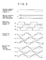
- means for generating a midpoint 20 outputs a midpoint signal having an electric potential of which value is a median of electric potentials of the current instruction signals a and b. As shown in Fig. 2 and the after-mentioned Fig. 3, in this embodiment, an electric potential of the midpoint signal is a ground level (zero level).
- the current instruction signals a, b and the midpoint signal are input in signal selection means 11.
- the signal selection means 11 receives the current instruction signals a and b that are analogue signals, the midpoint signal with a ground level, and the position detecting signal group h (hu, hv, hw) that is logical signals. In response to the position detecting signal group h (hu, hv, hw), the signal selection means 11 selects one of the following: current instruction signals a, b and the midpoint signal. Then, the signal selection means 11 generates and outputs a selection signal group s (su, sv, sw) that becomes modulated waves of PWM control.
- Pulse edges of the selection signal group s are synchronized with those of the position detecting signal group h (hu, hv, hw). For example, as shown in Fig. 2, rising and falling edges of a positive direction pulse of the selection signal su (when the current instruction signal a is selected) are synchronized with falling edge of the position detecting signal hu and falling edge of the position detecting signal hv respectively.
- edges of a negative direction pulse of the selection signal su are synchronized with a rising edge of the position detecting signal hu and a risng edge of the position detecting signal hv respectively.
- edges of the selection signal sv are synchronized with edges of the position detecting signals hv and hw
- edges of the selection signal sw are synchronized with edges of the position detecting signals hw and hu.
- a high level voltage of the selection signal group s (su, sv, sw) agrees with a voltage level of the current instruction signal a.
- a low level voltage agrees with a voltage level of the current instruction signal b.
- a voltage level of the selection signal group s may also have a value proportional to a voltage level of the current instruction signals a and b.
- the selection signal group s (su, sv, sw) is input to a filter circuit 10, which processes the selection signal group s so that a waveform of each selection signal becomes smooth.
- the filter circuit 10 outputs signals with smooth waveforms as selection signals fu, fv, fw.
- a comparator 9 compares the selection signals fu, fv, fw with a carrier wave signal (for example, a triangular wave), which is output of a carrier generator 14, to generate a PWM signal.
- the PWM signal is input to the inverter driving unit 8, which in turn controls on/off state of each switching element of the inverter unit 3.
- the configuration described above controls a motor rotational speed so that the motor rotational speed agrees with a speed instruction given by the means for speed control operation 13. More specifically, when the motor rotational speed is lower than a value of the speed instruction, a value of the current instruction signal a is increased. This increases amplitudes of the selection signal group s (su, sv, sw) causing on-duty ratio of the PWM signal to increase. Accordingly, output current of the inverter unit 3 increases, which produces increased motor torque to accelerate the motor, resulting in the motor rotational speed that accords with the speed instruction value. When the motor rotational speed is higher than the speed instruction value, a value of the current instruction signal a is decreased. This performs the above-mentioned steps in reverse causing the motor to decelerate, which results in the motor rotational speed that accords with the speed instruction value.
- a motor current instruction signal which is a direct-current voltage
- a position detecting signal as appropriate
- rectangular modulated waves are generated for PWM control. Therefore, relatively simple PWM control can drive a brushless motor.
- a driving circuit becomes simple, a brushless motor driving circuit can be miniaturized.
- the simplified circuit enables us to generate a PWM signal, which has been generated by the means for speed control operation (such as a microcomputer) in the prior art, in a control circuit that is integrally formed in the monolithic semiconductor integrated circuit 6 on which the inverter unit 3 is mounted.
- a PWM control circuit, an inverter driving unit (a driver circuit for switching element), and an inverter main circuit can be integrated in an one-chip monolithic IC.
- This can reduce a load of a processor such as a microcomputer, which performs various kinds of controls or state monitoring of the motor driving system. Accordingly, a small or low-cost processor can be used.
- the semiconductor integrated circuit 6 incorporates a speed-instruction-value setting circuit and a circuit for generating the current instruction signal a as described above, the means for speed control operation 13 becomes unnecessary.
- a filter circuit smoothes waveforms of the selection signal group s (sv, su, sw).
- direct use of the selection signal group s (sv, su, sw) as modulated waves also provides smoother motor current waveforms than those provided by the 120-degree energizing method.
- an inverter-output-off period corresponding to 60 degrees in electrical angle for the 120-degree energizing method
- PWM control with a duty ratio of 50% is performed. Therefore, motor current flows during this period, contributing to smooth current waveforms. This is the reason why the motor current waveforms become smooth.
- providing a filter circuit produces smoother current waveforms, which results in a lower motor noise.
- FIG. 3 A method for selecting the current instruction signal of this embodiment is specifically described with reference to Fig. 3.
- position detecting signals hu, hv, hw as logical signals are distributed by a signal distribution circuit 31, and are output as driving signals ut, um, ub, vt, vm, vb, wt, wm, wb of an analogue switch group 32.
- Fig. 4 shows distribution signal waveforms.
- the driving signals ut, um, ub become high level respectively.
- Embodiment 2 will be described with reference to Fig. 5. Although a drawing of the embodiment 2 is omitted, a driving system configuration of this embodiment is similar to that of the embodiment shown in Fig. 1. The difference between those embodiments is that a number of the current instruction signal levels to be selected is increased from three levels (a, ground, b) to four levels (a, c, d, b).
- a selection signal for each phase is formed by a switching signal with 60 degrees + 120 degrees, whereas in this embodiment a selection signal is segmented for each 60 degrees.
- a selection signal group s is generated from current instruction signals and a position detecting signal group h.
- the current instruction signals are four direct-current levels a, b, c, d that have been converted from motor current instruction a.
- Fig. 6 illustrates a circuit configuration for generating selection signals specifically.
- the gain z is adjusted so as to correspond to an inductive-voltage waveform level of a motor.
- selection signals shown in Fig. 5 are compared with a sine wave.
- level c if level a is 1, a 30-degree position of the sine wave is an average position.
- a signal distribution circuit has a logical configuration as shown in Fig. 7.
- the logical configuration is almost the same as that of the embodiment shown in Fig. 4.
- each of signal distribution outputs ut, uh, ul, ub becomes high level.
- each switch connected to each of the current instruction signals a, c, b, d is switched on.
- su shown in Fig. 5 is generated.
- the other selection signals sv, sw are also generated in the same manner.
- output signals of the distribution circuit are given to an analogue switch group 32 to select direct-current signals a, b, c, d.
- the selected signals are input to amplifier 33, of which output signals are input to a filter circuit.
- resolution of the selection signals is increased, which produces the great effect of reducing a noise.
- direct comparison of the selection signal group s with carrier waves without using the filter circuit also produces smooth motor current to some extent. Accordingly, removing the filter circuit eliminates the influence of the filter-circuit time constant, resulting in decrease of a noise over a wide range of rotational frequency.
- the logical configuration shown in Fig. 7 can be automatically generated from the position detecting signals.
- a phase relation between the position detecting signals and the selection signals can also be shifted using a logical means.
- a phase difference of position detection between two operation points, at which a rotational frequency is extremely different from the other, is extremely large, it is possible to deal with such case by changing a logical configuration of the signal distribution circuit in the driving circuit of this embodiment.
- the filter circuit shown in Fig. 3 which is a primary delay circuit with a simple configuration comprising resistors and capacitors, may be replaced with a filter circuit with a complicated configuration (for example, a multistage CR filter).
- the filter circuit 10 smoothes stepped signals using a frequency in response to a fixed time constant. Accordingly, motor current is smoothed at a specific motor rotational frequency.
- a time constant of the filter may also be changed in response to a rotational frequency. Therefore, if a variable time-constant filter is applied to a motor covering a wide range of rotational frequency for use, a noise is reduced while maintaining a motor efficiency.
- an inverter unit 6 which incorporates a monolithic semiconductor integrated circuit comprising the driving circuit described in the embodiments 1 and 2, is integrated into a motor monolithically.
- a stator 52 comprising motor winding is mounted to a motor enclosure 51. Winding input terminals 58 are attached to the stator 52.
- a permanent magnet rotor 53 is mounted inside the stator 52 while providing the permanent magnet rotor 53 with an appropriate gap to prevent the rotor 53 from contacting the stator 52.
- the monolithic semiconductor integrated circuit 6 that incorporates the inverter unit of this embodiment, the magnetic-pole position detector (Hall IC) 5 for detecting a magnetic pole position of the rotor, and substrate 54 having peripheral circuits are mounted on the rotor 53, which are additionally covered with enclosure 55.
- All IC magnetic-pole position detector
- the position detector 5 is shown on the surface (upward direction) of the substrate for convenience of description, the position detector 5 is actually mounted on the backside of the substrate to put it near the rotor for easier detection of a magnetic-pole position of the rotor.
- winding input terminals 58 on the stator side are connected to inverter output terminals 57 with wiring 56.
- wiring 59 for driving the inverter is pulled out from the substrate 54.
- the minimum number of wiring required to drive the motor is five: the plus side of high voltage power supply for driving the motor; its minus side (ground), the plus side of control power supply for the monolithic integrated circuit; input signal for controlling motor current; and output signal of motor rotation.
- the number of wiring can be significantly reduced as compared with the case where the motor driving circuit is mounted outside the motor enclosure.
- Fig. 9 illustrates a cross section of a monolithic semiconductor integrated circuit, in which a motor driving circuit is formed, according to this embodiment.
- the integrated circuit is formed above a dielectric separation substrate.
- a silicon oxide film (SiO 2 ) 42 that is a dielectric (insulator)
- IGBT semiconductor switching element
- IGBT semiconductor switching element
- Those electrical components are connected to conductor wiring 43.
- Each single crystal island 44 is electrically isolated from the others by the silicon oxide film 42, and supported by a polycrystalline silicon substrate 41 that covers the single crystal island 44 and the silicon oxide film 42.
- Fig. 10 illustrates a plane pattern of a monolithic semiconductor integrated circuit shown in Fig. 9.
- a monolithic integrated-circuit chip 45 there are an area on which six high speed diode 46 are mounted in such a manner as to be adjacent to each other, and an area on which six IGBTs 47 are mounted in such a manner as to be adjacent to each other.
- Those semiconductor elements constitute the inverter unit. Adjacent to the area where the IGBTs are mounted, an inverter driving unit for controlling on/off state of those IGBTs and a circuit for generating PWM signal are formed above an area 48.
- Each circuit area is formed above the above-mentioned single crystal island 44 that is isolated from the substrate by the silicon oxide film 42.
- a circuit configuration of the area 48 is the same as those of the embodiments 1 through 3, the circuit configuration of the area 48 becomes relatively simple although the inverter driving unit and the circuit for generating PWM signal are included. This results in a small area occupied by the area 48 on a chip. Therefore, the inverter unit, the inverter driving unit, and the circuit for generating PWM signal can be embedded in a small size chip.
Abstract
Description
Claims (15)
- A driving circuit of a motor having winding of a stator and having a permanent magnet rotor, said motor driving circuit comprising:a power converter for supplying the motor with pulse-width modulated driving power;a means for detecting a magnetic-pole position of the rotor of the motor;a means for detecting a rotational speed of the motor from output of the means for detecting a magnetic-pole position;a means for outputting a deviation of the detected rotational speed of the motor from a speed instruction;a means for generating a plurality of instruction signals in response to the deviation;a signal selection means that selects one of the plurality of instruction signals according to the magnetic-pole position of the motor, and that outputs a selection signal group;a means for generating modulated waves from the selection signal group and a carrier wave signal; anda means for controlling the power converter by means of pulse width modulation according to the modulated waves.
- A motor driving circuit according to Claim 1, wherein:
said plurality of instruction signals have a plurality of direct-current levels; and said modulated waves has levels that correspond to the direct-current levels. - A motor driving circuit according to Claim 1, wherein:
a filter circuit is provided between output of the signal detection means and the means for generating modulated waves. - A semiconductor integrated circuit device, comprising in the same semiconductor substrate:a semiconductor switching element for supplying a motor with pulse-width modulated power;a means for generating a plurality of instruction signals in response to a deviation of a rotational speed signal of the motor from a speed instruction;a means for selecting one of the plurality of instruction signals to generate modulated waves, in response to a magnetic-pole position detection signal of the motor; anda means for controlling the semiconductor switching element by means of pulse width modulation according to the modulated waves.
- A semiconductor integrated-circuit according to Claim 4, wherein:
said semiconductor switching element formed above the same semiconductor substrate is isolated from a means for driving the semiconductor switching element by a dielectric. - A semiconductor integrated-circuit according to Claim 4, wherein:
said semiconductor switching element is an IGBT. - A motor driving system comprising:a motor having a stator with winding and having a permanent magnetic rotor that is placed inside the stator;a power converter for supplying the motor with pulse-width modulation controlled driving power;a magnetic-pole position detector for detecting a magnetic-pole position of the motor rotor;a speed detecting means for detecting a rotational speed of the motor according to an output signal of the magnetic-pole position detector;a speed control operation means for outputting a deviation of an output signal of the speed detecting means from a speed instruction;a means for generating a plurality of instruction signals in response to an output signal of the speed control operation means;a means for generating modulated waves by selecting one of the plurality of instruction signals according to the output signal of the speed control operation means; anda means for controlling the power converter by means of pulse width modulation according to the modulated waves.
- A motor driving system according to Claim 7, wherein:
said motor is a three-phase brushless motor. - A motor driving system according to Claim 7, wherein:
the magnetic-pole position detector is a Hall IC with a zero-crossing circuit. - A motor driving system according to Claim 7, wherein:
above the same semiconductor substrate are formed:
the power converter; the means for generating a plurality of instruction signals; the means for generating modulated waves by selecting one of the plurality of instruction signals; and the means for controlling the power converter by means of pulse width modulation. - A motor driving system according to Claim 7, wherein:
said power converter is an inverter unit having a diode and an IGBT. - A motor comprising a stator with winding, a permanent magnetic rotor that is placed inside the stator, and an enclosure for accommodating the stator and the rotor, wherein the motor is driven by a driving circuit,
said driving circuit comprising:a power converter for supplying the motor with pulse-width modulated driving power;a means for detecting a magnetic-pole position of the rotor of the motor;a means for detecting a rotational speed of the motor from output of the means for detecting magnetic-pole position;a means for outputting a deviation of the detected rotational speed of the motor from a speed instruction;a means for generating a plurality of instruction signals in response to the deviation;a signal selection means that selects one of the plurality of instruction signals according to the magnetic-pole position of the motor, and that outputs a selection signal group;a means for generating modulated waves from the selection signal group and a carrier wave signal; anda means for controlling the power converter by means of pulse width modulation according to the modulated waves;wherein said motor driving circuit is built into the enclosure. - A motor according to Claim 12, wherein:
the following are formed above the same semiconductor substrate as a semiconductor integrated-circuit:a semiconductor switching element for supplying the motor with pulse-width modulated power in the driving circuit;a means for generating a plurality of instruction signals in response to a deviation of a rotational speed signal of the motor from a speed instruction;a means for selecting one of the plurality of instruction signals to generate modulated waves, in response to a magnetic-pole position detection signal of the motor; anda means for controlling the semiconductor switching element by means of pulse width modulation according to the modulated waves. - A motor according to Claim 13, wherein:
the magnetic-pole position detector is placed nearer to the permanent magnet rotor than to the semiconductor integrated circuit. - A method for driving a brushless motor using a power converter that is controlled by means of pulse width modulation, comprising the steps of:
generating a deviation of a motor rotational speed, which has been generated from a magnetic-pole position detection signal group of a motor rotor, from a speed instruction;generating a plurality of instruction signals according to the deviation;selecting one of the plurality of instruction signals to generate modulated waves, according to the magnetic-pole position of the motor rotor; andcontrolling the power converter by means of pulse width modulation according to the modulated waves.
Applications Claiming Priority (2)
| Application Number | Priority Date | Filing Date | Title |
|---|---|---|---|
| JP2000058021A JP3442024B2 (en) | 2000-02-29 | 2000-02-29 | Motor driving circuit, motor driving method, and semiconductor integrated circuit device |
| JP2000058021 | 2000-02-29 |
Publications (2)
| Publication Number | Publication Date |
|---|---|
| EP1130761A2 true EP1130761A2 (en) | 2001-09-05 |
| EP1130761A3 EP1130761A3 (en) | 2004-09-29 |
Family
ID=18578678
Family Applications (1)
| Application Number | Title | Priority Date | Filing Date |
|---|---|---|---|
| EP01104158A Withdrawn EP1130761A3 (en) | 2000-02-29 | 2001-02-21 | A motor driving circuit, a method for driving a motor, and a semiconductor integrated circuit device |
Country Status (6)
| Country | Link |
|---|---|
| US (1) | US6534948B2 (en) |
| EP (1) | EP1130761A3 (en) |
| JP (1) | JP3442024B2 (en) |
| KR (1) | KR100739376B1 (en) |
| CN (2) | CN1187887C (en) |
| TW (1) | TW515140B (en) |
Cited By (5)
| Publication number | Priority date | Publication date | Assignee | Title |
|---|---|---|---|---|
| GB2416079A (en) * | 2004-05-10 | 2006-01-11 | Premark Feg Llc | Mixing device with variable frequency AC motor drive |
| EP1653904A2 (en) * | 2003-08-04 | 2006-05-10 | Pulmonetic Systems, Inc. | Compressor control system for a portable ventilator |
| US7207711B2 (en) | 2002-12-23 | 2007-04-24 | Premark Feg L.L.C. | Mixing device with variable speed drive and related control features |
| US8888711B2 (en) | 2008-04-08 | 2014-11-18 | Carefusion 203, Inc. | Flow sensor |
| US10118011B2 (en) | 2003-08-04 | 2018-11-06 | Carefusion 203, Inc. | Mechanical ventilation system utilizing bias valve |
Families Citing this family (42)
| Publication number | Priority date | Publication date | Assignee | Title |
|---|---|---|---|---|
| EP1378990B1 (en) * | 2001-03-02 | 2007-12-12 | Matsushita Electric Industrial Co., Ltd. | Electric motor controller |
| JP4113339B2 (en) * | 2001-06-18 | 2008-07-09 | 日本サーボ株式会社 | Three-phase annular coil permanent magnet type rotating electrical machine |
| JP4226236B2 (en) * | 2001-09-07 | 2009-02-18 | パナソニック株式会社 | Motor control device |
| EP1351376A1 (en) * | 2002-03-11 | 2003-10-08 | Askoll Holding S.r.l. | Electronic device for starting and controlling a permanent-magnet synchronous motor |
| US6828753B2 (en) * | 2002-08-26 | 2004-12-07 | International Rectifier Corporation | Input filter for A.C. motor phase current sensing |
| EP1843463B1 (en) * | 2002-12-12 | 2013-07-03 | Panasonic Corporation | Motor control apparatus |
| JP2004208450A (en) * | 2002-12-26 | 2004-07-22 | Sanden Corp | Motor controller |
| JP2004242432A (en) * | 2003-02-06 | 2004-08-26 | Canon Inc | Direct-current motor drive |
| ES2592262T3 (en) | 2003-08-04 | 2016-11-29 | Carefusion 203, Inc. | Portable respirator system |
| US8156937B2 (en) | 2003-08-04 | 2012-04-17 | Carefusion 203, Inc. | Portable ventilator system |
| US7607437B2 (en) | 2003-08-04 | 2009-10-27 | Cardinal Health 203, Inc. | Compressor control system and method for a portable ventilator |
| DE10339028A1 (en) * | 2003-08-25 | 2005-03-31 | Siemens Ag | Method and apparatus for controlling a brushless DC motor |
| US8154227B1 (en) | 2003-11-26 | 2012-04-10 | Liontech Trains Llc | Model train control system |
| US7312590B1 (en) | 2003-11-26 | 2007-12-25 | The Creative Train Company, Llc | Model railroad velocity controller |
| US8030871B1 (en) | 2003-11-26 | 2011-10-04 | Liontech Trains Llc | Model train control system having realistic speed control |
| US8013550B1 (en) | 2003-11-26 | 2011-09-06 | Liontech Trains Llc | Model train remote control system having realistic speed and special effects control |
| US7049778B2 (en) * | 2004-02-09 | 2006-05-23 | Nippon Yusoki Co., Ltd. | Inverter control apparatus and inverter control method |
| CN1756707A (en) * | 2004-03-02 | 2006-04-05 | 三菱电机株式会社 | Elevator control device |
| JP4552466B2 (en) * | 2004-03-12 | 2010-09-29 | 株式会社日立製作所 | AC motor control device, 2-chip inverter and one-chip inverter. |
| US7501733B2 (en) * | 2004-05-18 | 2009-03-10 | Seiko Epson Corporation | Electric machine |
| KR100662434B1 (en) * | 2005-11-17 | 2007-01-02 | 엘지전자 주식회사 | Driving device in washing machine and washing machine with the same |
| US7274163B1 (en) * | 2006-03-31 | 2007-09-25 | Lexmark International, Inc. | Methods and apparatus for commutating a brushless DC motor in a laser printer |
| JP4218730B2 (en) * | 2006-04-26 | 2009-02-04 | 双葉電子工業株式会社 | Servo device |
| CN101086475B (en) * | 2006-06-09 | 2011-11-30 | 深圳迈瑞生物医疗电子股份有限公司 | Air measuring device with rotation speed automatic control function and air measuring method |
| JP4557955B2 (en) * | 2006-11-08 | 2010-10-06 | 株式会社日立製作所 | Motor driving circuit, motor driving method, and semiconductor integrated circuit device |
| CN103973176B (en) * | 2007-11-16 | 2017-06-30 | 台达电子工业股份有限公司 | Motor apparatus and motor control speed system |
| US7997885B2 (en) | 2007-12-03 | 2011-08-16 | Carefusion 303, Inc. | Roots-type blower reduced acoustic signature method and apparatus |
| CN101729009B (en) * | 2008-10-21 | 2013-01-16 | 深圳万讯自控股份有限公司 | Control system of direct current motor |
| EP2657626B1 (en) * | 2010-12-21 | 2020-11-25 | Mitsubishi Electric Corporation | Heat pump device, heat pump system, and method for controlling three-phase inverter |
| JP5320420B2 (en) * | 2011-02-18 | 2013-10-23 | 株式会社日立ハイテクインスツルメンツ | Motor control device and motor control method |
| JP2012196048A (en) * | 2011-03-16 | 2012-10-11 | Canon Inc | Motor drive device |
| US9236777B2 (en) * | 2011-04-08 | 2016-01-12 | Bison Gear & Engineering Corp. | Bobbin wound motor |
| CN202172378U (en) * | 2011-08-04 | 2012-03-21 | 中山大洋电机制造有限公司 | DC brushless motor controller using AC electric signal to control motor at constant rotating speed running |
| WO2013111326A1 (en) * | 2012-01-27 | 2013-08-01 | 三菱電機株式会社 | Motor drive circuit and permanent magnet synchronous motor |
| CN102820848A (en) * | 2012-08-15 | 2012-12-12 | 欧瑞传动电气有限公司 | VOC voltage automatic adjusting method and frequency converter using same |
| US9523947B2 (en) | 2012-09-26 | 2016-12-20 | Lexmark International, Inc. | Time-based commutation method and system for controlling a fuser assembly |
| US8836747B2 (en) | 2012-10-02 | 2014-09-16 | Lexmark International, Inc. | Motor control system and method for a laser scanning unit of an imaging apparatus |
| US10944352B2 (en) * | 2018-03-19 | 2021-03-09 | Tula eTechnology, Inc. | Boosted converter for pulsed electric machine control |
| JP7189421B2 (en) * | 2018-09-21 | 2022-12-14 | ミツミ電機株式会社 | Motor drive circuit and motor drive device |
| WO2021024378A1 (en) * | 2019-08-06 | 2021-02-11 | 三菱電機株式会社 | Motor drive system and motor drive device |
| CN110611462B (en) * | 2019-10-17 | 2021-01-15 | 江苏科技大学 | Three-stage rotating speed indicating device and method for brushless direct current motor |
| JP2021072373A (en) * | 2019-10-31 | 2021-05-06 | セイコーエプソン株式会社 | Motor drive circuit, integrated circuit device, and electronic apparatus |
Citations (2)
| Publication number | Priority date | Publication date | Assignee | Title |
|---|---|---|---|---|
| EP0464644A1 (en) * | 1990-07-06 | 1992-01-08 | Hitachi, Ltd. | Brushless motor incorporating an integrated circuit having a one-chipped peripheral circuit |
| US5821707A (en) * | 1995-09-22 | 1998-10-13 | Lg Electronics Inc. | Inverter controller for brushless direct current motor |
Family Cites Families (15)
| Publication number | Priority date | Publication date | Assignee | Title |
|---|---|---|---|---|
| US4855652A (en) * | 1987-01-28 | 1989-08-08 | Hitachi, Ltd. | Speed control apparatus for a brushless direct current motor |
| US5463299A (en) * | 1989-06-07 | 1995-10-31 | Hitachi, Ltd. | Current controller for controlling a current flowing in a load using a PWM inverter and method used thereby |
| US5350988A (en) * | 1990-07-10 | 1994-09-27 | Alliedsignal, Inc. | Digital motor controller |
| JPH04236190A (en) * | 1991-01-11 | 1992-08-25 | Toyota Motor Corp | Electric controller for brushless motor |
| FR2717014B1 (en) * | 1994-03-01 | 1996-04-26 | Telemecanique | PWM inverter control system. |
| JPH0819283A (en) * | 1994-06-28 | 1996-01-19 | Fujitsu General Ltd | Control method for brushless motor |
| JPH0835712A (en) * | 1994-07-26 | 1996-02-06 | Fujitsu General Ltd | Controller for air conditioner |
| JPH0947026A (en) * | 1995-07-25 | 1997-02-14 | Mitsubishi Electric Corp | Pwm waveform generator |
| EP0856936B1 (en) * | 1995-10-06 | 2004-05-06 | Hitachi, Ltd. | Motor controller |
| JPH11502700A (en) * | 1996-01-24 | 1999-03-02 | フィリップス エレクトロニクス ネムローゼ フェンノートシャップ | Apparatus, drive system, and disk drive for supplying drive signal to multi-phase multi-phase DC motor |
| KR200143530Y1 (en) * | 1996-06-28 | 1999-06-15 | 윤종용 | Driving current control apparatus of a switched reluctance motor |
| US5914582A (en) * | 1997-01-27 | 1999-06-22 | Hitachi, Ltd. | Permanent magnet synchronous motor controller and electric vehicle controller |
| JPH11113283A (en) * | 1997-09-30 | 1999-04-23 | Toshiba Corp | Motor driver |
| JP3483760B2 (en) * | 1998-03-25 | 2004-01-06 | 株式会社東芝 | Drive device for permanent magnet motor |
| EP0961396B1 (en) * | 1998-05-28 | 2005-09-28 | Ibiden Co., Ltd. | Motor-driving circuit |
-
2000
- 2000-02-29 JP JP2000058021A patent/JP3442024B2/en not_active Expired - Fee Related
-
2001
- 2001-01-18 TW TW090101168A patent/TW515140B/en not_active IP Right Cessation
- 2001-02-21 US US09/790,203 patent/US6534948B2/en not_active Expired - Fee Related
- 2001-02-21 EP EP01104158A patent/EP1130761A3/en not_active Withdrawn
- 2001-02-26 KR KR1020010009697A patent/KR100739376B1/en not_active IP Right Cessation
- 2001-02-28 CN CNB011089229A patent/CN1187887C/en not_active Expired - Fee Related
- 2001-02-28 CN CNB2004100978684A patent/CN1300930C/en not_active Expired - Fee Related
Patent Citations (2)
| Publication number | Priority date | Publication date | Assignee | Title |
|---|---|---|---|---|
| EP0464644A1 (en) * | 1990-07-06 | 1992-01-08 | Hitachi, Ltd. | Brushless motor incorporating an integrated circuit having a one-chipped peripheral circuit |
| US5821707A (en) * | 1995-09-22 | 1998-10-13 | Lg Electronics Inc. | Inverter controller for brushless direct current motor |
Non-Patent Citations (2)
| Title |
|---|
| PATENT ABSTRACTS OF JAPAN vol. 1996, no. 05, 31 May 1996 (1996-05-31) & JP 08 019283 A (FUJITSU GENERAL LTD), 19 January 1996 (1996-01-19) * |
| PATENT ABSTRACTS OF JAPAN vol. 2000, no. 01, 31 January 2000 (2000-01-31) & JP 11 275882 A (TOSHIBA CORP), 8 October 1999 (1999-10-08) * |
Cited By (9)
| Publication number | Priority date | Publication date | Assignee | Title |
|---|---|---|---|---|
| US7207711B2 (en) | 2002-12-23 | 2007-04-24 | Premark Feg L.L.C. | Mixing device with variable speed drive and related control features |
| US7273315B2 (en) | 2002-12-23 | 2007-09-25 | Premark Feg Llc | Mixing device with variable speed drive and related control features |
| EP1653904A2 (en) * | 2003-08-04 | 2006-05-10 | Pulmonetic Systems, Inc. | Compressor control system for a portable ventilator |
| EP1653904A4 (en) * | 2003-08-04 | 2007-04-04 | Pulmonetic Systems Inc | Compressor control system for a portable ventilator |
| US10118011B2 (en) | 2003-08-04 | 2018-11-06 | Carefusion 203, Inc. | Mechanical ventilation system utilizing bias valve |
| GB2416079A (en) * | 2004-05-10 | 2006-01-11 | Premark Feg Llc | Mixing device with variable frequency AC motor drive |
| US8888711B2 (en) | 2008-04-08 | 2014-11-18 | Carefusion 203, Inc. | Flow sensor |
| US9375166B2 (en) | 2008-04-08 | 2016-06-28 | Carefusion 203, Inc. | Flow sensor |
| US9713438B2 (en) | 2008-04-08 | 2017-07-25 | Carefusion 203, Inc. | Flow sensor |
Also Published As
| Publication number | Publication date |
|---|---|
| TW515140B (en) | 2002-12-21 |
| CN1300930C (en) | 2007-02-14 |
| KR20010085610A (en) | 2001-09-07 |
| EP1130761A3 (en) | 2004-09-29 |
| CN1187887C (en) | 2005-02-02 |
| CN1630179A (en) | 2005-06-22 |
| US20010040440A1 (en) | 2001-11-15 |
| KR100739376B1 (en) | 2007-07-16 |
| CN1311559A (en) | 2001-09-05 |
| US6534948B2 (en) | 2003-03-18 |
| JP3442024B2 (en) | 2003-09-02 |
| JP2001251886A (en) | 2001-09-14 |
Similar Documents
| Publication | Publication Date | Title |
|---|---|---|
| US6534948B2 (en) | Motor driving circuit, a method for driving a motor, and a semiconductor integrated circuit device | |
| US7141943B2 (en) | Brushless DC motor system and method of controlling the same | |
| US6828752B2 (en) | Driving equipment and semiconductor equipment for alternating-current motor | |
| US7224133B2 (en) | Control apparatus, dual chip inverter and single chip inverter of AC motors | |
| US7839113B2 (en) | Apparatus and method for driving synchronous motor | |
| KR101046354B1 (en) | Motor and motor drive system, motor drive circuit device, method for driving motor and semiconductor integrated circuit device | |
| US8232759B2 (en) | Pseudo current type 120-degree conduction inverter | |
| US8421395B2 (en) | Synchronous motor and control method of synchronous motor | |
| JP4023353B2 (en) | Inverter circuit device for three-phase rotating electrical machine for vehicles | |
| US5793169A (en) | Method and apparatus for controlling static electronic components for phase switching in a three-phase brushless electric motor | |
| JP2009247089A (en) | Method of controlling inverters for brushless motors and device using the same | |
| WO2003084047A1 (en) | Controller for a brushless dc motor | |
| KR100457360B1 (en) | Control system and method for reducing a commutation torque ripple of a brushless dc motor | |
| US5852356A (en) | DC/AC inverter for power supply to an electrical motor for the traction of a vehicle | |
| KR20010079870A (en) | Electric drive system with an electronically commuted D.C. motor in order to reduce torque irregularities | |
| JPH07236294A (en) | Inverter apparatus | |
| JP2002335689A (en) | Motor drive circuit | |
| JP2002119084A (en) | Sensorless/brushless dc motor-driving device | |
| JPH07222487A (en) | Driving apparatus of brushless motor | |
| JP2827986B2 (en) | Induction motor control method and device | |
| JPH1155994A (en) | Step-out preventing method for sensorless synchronous motor | |
| KR19980036724A (en) | Brushless Motor Control Circuit | |
| KR980012825A (en) | Converter for SALM Motor | |
| JPH0683589B2 (en) | Controller for non-commutator motor |
Legal Events
| Date | Code | Title | Description |
|---|---|---|---|
| PUAI | Public reference made under article 153(3) epc to a published international application that has entered the european phase |
Free format text: ORIGINAL CODE: 0009012 |
|
| AK | Designated contracting states |
Kind code of ref document: A2 Designated state(s): AT BE CH CY DE DK ES FI FR GB GR IE IT LI LU MC NL PT SE TR |
|
| AX | Request for extension of the european patent |
Free format text: AL;LT;LV;MK;RO;SI |
|
| PUAL | Search report despatched |
Free format text: ORIGINAL CODE: 0009013 |
|
| AK | Designated contracting states |
Kind code of ref document: A3 Designated state(s): AT BE CH CY DE DK ES FI FR GB GR IE IT LI LU MC NL PT SE TR |
|
| AX | Request for extension of the european patent |
Extension state: AL LT LV MK RO SI |
|
| RIC1 | Information provided on ipc code assigned before grant |
Ipc: 7H 02P 6/10 B Ipc: 7H 02P 6/06 B Ipc: 7H 02P 6/16 A |
|
| 17P | Request for examination filed |
Effective date: 20050322 |
|
| AKX | Designation fees paid |
Designated state(s): DE FR GB |
|
| GRAP | Despatch of communication of intention to grant a patent |
Free format text: ORIGINAL CODE: EPIDOSNIGR1 |
|
| RTI1 | Title (correction) |
Free format text: A MOTOR DRIVING CIRCUIT OF A BRUSHLESS MOTOR |
|
| STAA | Information on the status of an ep patent application or granted ep patent |
Free format text: STATUS: THE APPLICATION IS DEEMED TO BE WITHDRAWN |
|
| 18D | Application deemed to be withdrawn |
Effective date: 20090430 |