EP1129944A1 - State of a moving body ( docking, rendezvous ) with three retro reflectors and state observer ( Luenberger ) - Google Patents
State of a moving body ( docking, rendezvous ) with three retro reflectors and state observer ( Luenberger ) Download PDFInfo
- Publication number
- EP1129944A1 EP1129944A1 EP01104452A EP01104452A EP1129944A1 EP 1129944 A1 EP1129944 A1 EP 1129944A1 EP 01104452 A EP01104452 A EP 01104452A EP 01104452 A EP01104452 A EP 01104452A EP 1129944 A1 EP1129944 A1 EP 1129944A1
- Authority
- EP
- European Patent Office
- Prior art keywords
- state
- measurement
- vector
- retroreflectors
- observer
- Prior art date
- Legal status (The legal status is an assumption and is not a legal conclusion. Google has not performed a legal analysis and makes no representation as to the accuracy of the status listed.)
- Withdrawn
Links
- 238000003032 molecular docking Methods 0.000 title description 9
- 239000013598 vector Substances 0.000 claims abstract description 167
- 238000005259 measurement Methods 0.000 claims abstract description 138
- 238000000034 method Methods 0.000 claims abstract description 34
- 238000004364 calculation method Methods 0.000 claims abstract description 12
- 230000008569 process Effects 0.000 claims abstract description 8
- 239000011159 matrix material Substances 0.000 claims description 62
- 238000012937 correction Methods 0.000 claims description 12
- 238000011156 evaluation Methods 0.000 claims description 10
- 230000006399 behavior Effects 0.000 claims description 7
- 238000013459 approach Methods 0.000 claims description 6
- 238000012545 processing Methods 0.000 claims description 6
- 230000000694 effects Effects 0.000 claims description 4
- 230000001419 dependent effect Effects 0.000 claims description 2
- 238000003860 storage Methods 0.000 claims description 2
- 230000007704 transition Effects 0.000 claims 1
- 230000006870 function Effects 0.000 description 7
- 239000000243 solution Substances 0.000 description 5
- 230000005540 biological transmission Effects 0.000 description 3
- 238000005070 sampling Methods 0.000 description 3
- 230000008901 benefit Effects 0.000 description 2
- 230000004044 response Effects 0.000 description 2
- 230000001052 transient effect Effects 0.000 description 2
- 238000012935 Averaging Methods 0.000 description 1
- 230000006978 adaptation Effects 0.000 description 1
- 239000000969 carrier Substances 0.000 description 1
- 230000008859 change Effects 0.000 description 1
- 230000006735 deficit Effects 0.000 description 1
- 238000011161 development Methods 0.000 description 1
- 238000010586 diagram Methods 0.000 description 1
- 230000006872 improvement Effects 0.000 description 1
- 238000012432 intermediate storage Methods 0.000 description 1
- 238000012886 linear function Methods 0.000 description 1
- 230000036962 time dependent Effects 0.000 description 1
- 238000013519 translation Methods 0.000 description 1
Images


Classifications
-
- B—PERFORMING OPERATIONS; TRANSPORTING
- B64—AIRCRAFT; AVIATION; COSMONAUTICS
- B64G—COSMONAUTICS; VEHICLES OR EQUIPMENT THEREFOR
- B64G1/00—Cosmonautic vehicles
- B64G1/22—Parts of, or equipment specially adapted for fitting in or to, cosmonautic vehicles
- B64G1/64—Systems for coupling or separating cosmonautic vehicles or parts thereof, e.g. docking arrangements
- B64G1/646—Docking or rendezvous systems
-
- B—PERFORMING OPERATIONS; TRANSPORTING
- B64—AIRCRAFT; AVIATION; COSMONAUTICS
- B64G—COSMONAUTICS; VEHICLES OR EQUIPMENT THEREFOR
- B64G1/00—Cosmonautic vehicles
- B64G1/22—Parts of, or equipment specially adapted for fitting in or to, cosmonautic vehicles
- B64G1/24—Guiding or controlling apparatus, e.g. for attitude control
- B64G1/244—Spacecraft control systems
-
- G—PHYSICS
- G01—MEASURING; TESTING
- G01S—RADIO DIRECTION-FINDING; RADIO NAVIGATION; DETERMINING DISTANCE OR VELOCITY BY USE OF RADIO WAVES; LOCATING OR PRESENCE-DETECTING BY USE OF THE REFLECTION OR RERADIATION OF RADIO WAVES; ANALOGOUS ARRANGEMENTS USING OTHER WAVES
- G01S17/00—Systems using the reflection or reradiation of electromagnetic waves other than radio waves, e.g. lidar systems
- G01S17/87—Combinations of systems using electromagnetic waves other than radio waves
- G01S17/875—Combinations of systems using electromagnetic waves other than radio waves for determining attitude
-
- B—PERFORMING OPERATIONS; TRANSPORTING
- B64—AIRCRAFT; AVIATION; COSMONAUTICS
- B64G—COSMONAUTICS; VEHICLES OR EQUIPMENT THEREFOR
- B64G1/00—Cosmonautic vehicles
- B64G1/22—Parts of, or equipment specially adapted for fitting in or to, cosmonautic vehicles
- B64G1/24—Guiding or controlling apparatus, e.g. for attitude control
- B64G1/36—Guiding or controlling apparatus, e.g. for attitude control using sensors, e.g. sun-sensors, horizon sensors
-
- G—PHYSICS
- G01—MEASURING; TESTING
- G01S—RADIO DIRECTION-FINDING; RADIO NAVIGATION; DETERMINING DISTANCE OR VELOCITY BY USE OF RADIO WAVES; LOCATING OR PRESENCE-DETECTING BY USE OF THE REFLECTION OR RERADIATION OF RADIO WAVES; ANALOGOUS ARRANGEMENTS USING OTHER WAVES
- G01S5/00—Position-fixing by co-ordinating two or more direction or position line determinations; Position-fixing by co-ordinating two or more distance determinations
- G01S5/16—Position-fixing by co-ordinating two or more direction or position line determinations; Position-fixing by co-ordinating two or more distance determinations using electromagnetic waves other than radio waves
- G01S5/163—Determination of attitude
Definitions
- the invention relates to a method for determining the state variables of a moving rigid body in space, especially to determine the position and Position of a spaceship during an approach and docking maneuver.
- the easiest way to distance and look from a body To determine another, radar technology provides.
- the short wavelength of light enables high accuracy of the measured quantities distance, azimuth and Elevation (in spherical coordinates) or the components in Cartesian coordinates.
- the radar device emits a broadcast beam, which is the field in which the target object (also: target, e.g. space station, spaceship) is expected, scanned and from Target object is reflected.
- the reflection and thus the reliability of the measurement can be significantly improved if you use so-called retroreflectors used that exactly the incident beam in the opposite direction Rebound.
- the measuring beam leaves the transmitter optics and is guided line by line across the observation field by a coordinated movement of azimuth and elevation mirrors.
- the measuring beam hits a retroreflector, it is thrown back in the opposite direction and thus reaches the receiver optics of the radar device.
- the measurement data are determined by determining the mirror positions and calculating the distance from the transit time of the beam from the transmitter to the receiver. If you want to determine not only the position of the target, but also its position, you must use at least three retroreflectors, which are arranged in a defined manner in the coordinate system of the target. With such an arrangement of an active rangefinder (eg radar, rendezvous sensor) and three retroreflectors as example of Möbius, B.
- an active rangefinder eg radar, rendezvous sensor
- three retroreflectors as example of Möbius, B.
- the active sensor is often called the rendezvous sensor (RVS) - and the retroreflector arrangement (as system components of the measurement process) is fixed, i.e. does not move, you can use geometric relationships from the nine measurement values to determine a total of six parameters for the position and location of the two Determine coordinate systems to each other. If at least one of the two system components moves (e.g. when two spaceships are approaching and docking), a problem arises when evaluating the measured values because during the measurements on the three retroreflectors of the body scanned by the RVS, both the relative position and the position change and the measurement results can no longer be easily assigned. So far, approximate solutions based on triangular relationships have been used to determine the position and location, taking into account estimated values of the speeds. Another disadvantage of this solution is the extensive use of angle functions that are difficult to implement in on-board computers and can cause ambiguities.
- the invention has for its object a new way of determining of the state variables of a moving rigid body to find the one Simplification and higher reliability of the calculation of the State variables of the moving body ensures. It is an expanded task of the Invention, the aforementioned goals even with serial measurement value acquisition guarantee without increasing the evaluation effort.
- the object is achieved in a method for determining the state variables of a moving rigid body, such as relative position and position as well as translational and rotational speeds, in particular for moving the approach to another body using measurement data provided by an active sensor, the Measurement data from at least three retroreflectors, the configuration of which is known to be attached to the other body and is assigned to a body-specific coordinate system of the other body, are achieved in that the state variables of the moving body are determined with a state observer who measures the measurement data from samples of the processed individual retroreflectors in space by an internal memory model to the desired output signal of the state variables of the moving body, starting from set initial values and known implemented in operators n system parameters, a current state vector of the moving body is calculated as an estimate, and by means of a correction determined by linking the measurement data, this estimate is adapted to the actual position and movement behavior of the body with each measurement cycle, so that after a certain number of measurement and calculation cycles Estimates calculated in the state observer follow the current movement data of the body in space in
- the measurement data are advantageously compared with the estimated values present in the state observer, with a difference between a measurement vector y (k) and a current estimate y * (k) of the measurement vector on the basis of an estimated state vector x * (k), where k is a counting index current measurement and calculation cycles is determined and used to correct the estimated values.
- an estimated measurement vector y * (k) is made available from the currently estimated state vector x * (k) by means of an output matrix which contains the effect of the real state vector x (k) on the measurement vector y (k) an estimated comparison variable is generated, a subsequent state of the state vector x * (k) is calculated from the currently estimated state vector x * (k) via a system matrix, which takes into account the influences of the system when changing from a current state to a next state, and this Subsequent state is corrected by means of the difference using a feedback matrix, which contains a regulation for converting the difference into a correction of the current state, and after this correction results in a subsequent state vector x * (k + 1) which for the next cycle into the current state vector x * (k) is adopted.
- the state observer is set up as a filter, with an operator for generating a subsequent state, which links the relationship between the measurement vectors and two successive estimated state vectors x * (k) and x, from linking the output matrix and the feedback matrix with the system matrix * (k + 1) describes without knowledge of an estimated measurement vector, is generated, from the current estimated state vector x * (k) whose subsequent state is calculated by said operator, the generated subsequent state of the state vector is corrected with the converted measurement vector via the feedback matrix and in the subsequent state vector x * (k + 1) is transferred and the subsequent state vector x * (k + 1) is optionally provided in parallel to the current state vector x * (k) still present as an output of the state observer.
- a particularly simple variant of the invention consists in processing the measurement data from several retroreflectors sampled at the same time in the form of measurement vectors in the state observer at the same time as the measurement clock frequency of the retroreflector scans, a cycle clock of the calculations in the state observer corresponding to the measurement cycle of the scan of the retroreflectors.
- Another embodiment of the method according to the invention which is advantageous because of the savings in weight and volume is based on the fact that the measurement data in the form of measurement vectors from several successively scanned retroreflectors are processed in the state observer with a cycle clock frequency, the period of which corresponds to the duration of a series of scans of all retroreflectors with a measurement clock frequency are, the measuring clock frequency is an integer multiple of the cycle clock frequency depending on the number of retroreflectors used.
- the measurement vectors from the successively scanned retroreflectors are advantageously buffer-stored in the status observer, weighted depending on their chronological order and, after completion of a series of scans of all retroreflectors, processed simultaneously in one cycle cycle.
- the measurement vectors y i arriving one after the other are advantageously temporarily stored in a status observer constructed as a filter, depending on the measurement time by means of an associated feedback matrix and an evaluation matrix, which takes into account a time-dependent forgetting rate depending on the age of the individual measurement vectors y i , weighted differently and uses the specially evaluated and then summarized measurement vectors y i to correct the current state vector x * (k), which was previously multiplied by a matrix that embodies memory over n measurement cycles.
- the measurement data are processed in the form of measurement vectors from successively scanned retroreflectors in the state observer with a sampling frequency that corresponds to the average duration of the scans of each of the retroreflectors, with brief temporary storage in quasi real time.
- the measurement vectors which are each recorded in a defined sequence of the scanned retroreflectors, are processed without delay, an individual measurement vector y i (k) with a feedback matrix, which is associated with an output matrix specific for each retroreflector, advantageously being used in the state observer is evaluated, and in each case a subsequent state is calculated from the evaluated measurement vector y i (k) and the present current state vector x * (k), which is multiplied by a matrix representing the memory over a measurement cycle, the instant state for the processing of the next measurement vector y i + 1 (k + i ⁇ ) from the subsequently scanned retroreflector.
- the estimated state vector x * (k) is available after each measuring cycle.
- the body moves with the active sensor or the other body (hereinafter referred to as the target) with the retroreflectors.
- the target eg a space station or another spaceship
- the target is “fixed”, ie a movement of the target is irrelevant for the relative approach of the spaceship.
- the determined state variables of the spaceship can be used directly as results of the method according to the invention for controlling the moving spaceship.
- the active rendezvous sensor - without restricting generality - is referred to simply as laser radar, since it is preferably used.
- the number of retroreflectors is assumed to be three, since this is usually sufficient to exactly define an area in space (e.g. the docking area of the other body) in terms of position (distance) and position when the distribution of the retroreflectors appropriately chosen and known in its configuration.
- a measurement vector r 1 represents the actual measurement of the distance to a first retroreflector R 1.
- the measurement vector r 1 indicates in the coordinate system (x C , y C , z C ) of the laser radar where the retroreflector R 1 is located.
- a position vector p is specified which points to the origin of a coordinate system (x T , y T , z T ) of the target.
- target vectors t i are specified which point from its coordinate origin to the retroreflectors R i .
- target vectors t i are specified which point from its coordinate origin to the retroreflectors R i .
- Equation (2) shows how the state variables of the position with p (x, y, z) and the position with Q (q 1 , q 2 , q 3 , q 4 ) are included in the measurement result.
- q 1 , q 2 , q 3 , q 4 are quaternions that can describe the position of a body in relation to a fixed coordinate system instead of the Euler angle.
- quaternions represent an equivalent possibility of representing the position of a body with the body's own coordinate system in relation to another coordinate system. They have the advantage that they can be used to represent the position matrix Q in equation (2) without angular functions.
- Equation (2) The influence of the associated speeds is given by the time dependency and is recorded by repeated measurement of the retroreflectors R i . From equation (2) it follows that of the twelve state variables to be determined, only six state variables (x, y, z, q 1 , q 2 , q 3 ) determine the 3 components of the individual measurement vector r 1 . For this reason, a certain number of measurements must be carried out simultaneously and in succession on different and identical retroreflectors R i in order to compensate for the information deficit of only one measurement. Further equations analogous to equation (2) can be set up analogously for the other retroreflectors R i .
- the method according to the invention for determining the state variables mentioned, as shown in FIG. 2, is based on a principle of control engineering (observer by Luenberger [Föllinger, O .: control engineering, Wegig Buch Verlag, Heidelberg, 1990, pp. 501-517]) on.
- the upper part of FIG. 2 can be understood as a control system 1 (spacecraft with laser radar device) in the sense of control technology.
- These include an input vector u, an input matrix B, a system matrix A, a state vector x, an output matrix C and an output vector y.
- the input vector u in which the drive signals and possible interference signals are combined, determines the state vector x of the moving spaceship via the input matrix B.
- FIG. 2 there is a model of the moving body, a so-called state observer 2.
- the system parameters, ie the system matrix A and the output matrix C, of the controlled system 1 of the moving body and of the state observer 2 are assumed to be the same.
- the special adaptation of the status observer 2 to the measurement problem of the specified controlled system 1 consists in that an input vector u is not used in the status observer 2 since it is not available. Therefore, in the state observer, 2 estimates y * (k) of the output signal are generated, which ideally correspond to the measurement results r 1 , r 2 , r 3 of the laser radar.
- the next state is made up of a currently estimated state vector x * (k) and a correction e (k), which shows the deviation of the real measurement vector y (k) from that estimated in the state observer 2 Includes measurement vector y * (k), calculated.
- This correction e (k) thus also includes the influence of the input vector u from the controlled system 1.
- the estimated measurement vector y * (k) is generated from the estimated state vector x * (k) via an output matrix C, which contains the effect of the real state vector x (k) on the measurement vector y (k) measured by the laser radar.
- the correction e (k) obtained by forming the difference between the real measurement vector y (k) and the estimated measurement vector y * (k) is then via a feedback matrix H, which contains a regulation, to what extent the correction e (k) is based on the estimated State vector x * (k) affects, applied to the current estimated state vector x * (k), which results in the next estimated state, a subsequent state vector x * (k + 1).
- the following transmission element 22 symbolizes, as already in the controlled system 1 with 1 z -1 , that after one cycle the subsequent state vector x * (k + 1) is converted into the current estimated state vector x * (k).
- the state variables of the moving spaceship can then be read directly at the output of the state observer 2. If this correspondence does not exist, the state vector x * (k) of the state observer 2 is corrected with the aid of a correction vector e (k) using the feedback matrix H already mentioned until the error, ie the deviation between x (k) and x * (k) disappears.
- FIG. 3 shows the relationship between the real measurement vectors y (k) (input 21 of the state observer 2) and the estimated state vectors x * ( k) or x * (k + 1) (output 23 of the status monitor 2).
- the structure shown in FIG. 3 corresponds to that of a digital filter.
- the input variables of this filter are the measured values of the laser radar r 1 , r 2 , r 3 , which are combined as a real measurement vector y (k), and the sought-after state vectors x * (k) and x * (k + 1) represent the Output variables of the condition observer built as a filter.
- FIG. 3 shows how the (new) sequence state vector x * (k + 1) can be derived from the current state vector x * (k), multiplied by an operator 24 resulting from the matrices already introduced above, whose calculation rule is based on the matrix operation A - HC can be specified, and results from the simultaneously given measurement results y (k), which are weighted with the feedback matrix H.
- a filter is to be connected downstream of the laser radar device, which supplies the measured values r i , in order to be able to determine the desired state variables by evaluating the successive state vectors x * (k) and x * (k + 1).
- Equation (3) according to FIG. 3 is directly applicable if, for example, the positions and positions of the three retroreflectors R 1 , R 2 and R 3 are measured simultaneously with three laser beams.
- the condition observer 2 In the phase of greater distance, the state variables are smaller To measure accuracy, the condition observer 2 must settle faster can, i.e. the estimated measurement vectors y * (k) must match the real ones more quickly Measurement vectors y (k) can be approximated. In the immediate vicinity of the docking process the approach speed is low and it is therefore advisable to Condition observers to dimension 2 carriers, so that one through an effective Averaging receives a higher accuracy.
- FIG. 5 shows the state observer 2 according to the system of equations (4) in the form of a program loop 26. In contrast to FIG. 4, this shows that exactly one updated state vector x * is available after each measuring cycle.
- the state variables of the moving body can be used for many Win cases of sufficient accuracy.
- Another advantage of this variant of the method according to the invention is that the approximate position of the next retroreflector R i can also be calculated from the estimated state variables, which means an improvement of the measurement process by suitable selection of the field of view of the laser radar.
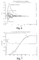
- FIG. 7 shows the manner in which the state observer according to FIG. 5 follows the changing state variables of the moving spaceship. If, for example, the quaternion q 1 (corresponds to the roll angle) changes almost suddenly, the condition observer follows in a relatively short time with an overshoot. At the same time, the quaternion q 2 (corresponds to the pitch angle) changes approximately sinusoidally, and the condition observer can follow very precisely. The estimate of the quaternion q 2 * generated by the state observer is practically equal to the real value q 2 .
- the other state variables also show almost the same behavior, as a result of which the performance of the last variant of the method according to the invention is impressively demonstrated. Similar results are also obtained for the basic variant of the invention. This also applies in the embodiment according to FIG. 4, in which - due to the necessity of a complete series of retroreflector scans in each case - the subsequent behavior of the state observer only has a coarser time grid when the state variables are output.
Abstract
Description
Die Erfindung betrifft ein Verfahren zur Bestimmung der Zustandsgrößen eines sich bewegenden starren Körpers im Raum, insbesondere zur Ermittlung der Position und Lage eines Raumschiffes bei einem Annäherungs- und Dockingmanöver.The invention relates to a method for determining the state variables of a moving rigid body in space, especially to determine the position and Position of a spaceship during an approach and docking maneuver.
In der Raumfahrt und in der Robotertechnik ist es oft erforderlich, Position und Lage
von zwei Körpern zueinander zu bestimmen. Besondere Bedeutung hat das in der
Raumfahrt beim Ankoppeln von Raumschiffen. So sind für die Steuerung des
Andockvorganges mindestens sechs Größen erforderlich:
Die einfachste Methode, den Abstand und die Blickrichtung von einem Körper zu einem anderen zu bestimmen, liefert die Radartechnik. Dabei haben sich für den Nahbereich, von einigen hundert Metern bis zu einigen Dezimetern, in letzter Zeit zunehmend Laser-Radar-Geräte durchgesetzt. Die kurze Wellenlänge des Lichtes ermöglicht hohe Genauigkeiten der zu messenden Größen Entfernung, Azimut und Elevation (in Kugelkoordinaten) oder der Komponenten in kartesischen Koordinaten. Das Radargerät sendet einen Sendestrahl aus, der das Feld, in dem das Zielobjekt (auch: Target, z.B. Raumstation, Raumschiff) erwartet wird, abtastet und vom Zielobjekt reflektiert wird. Die Reflexion und damit die Zuverlässigkeit der Messung kann wesentlich verbessert werden, wenn man sogenannte Retroreflektoren verwendet, die den einfallenden Strahl exakt in die entgegengesetzte Richtung zurückwerfen.The easiest way to distance and look from a body To determine another, radar technology provides. Here have for the Close range, from a few hundred meters to a few decimeters, recently Laser radar devices are becoming increasingly popular. The short wavelength of light enables high accuracy of the measured quantities distance, azimuth and Elevation (in spherical coordinates) or the components in Cartesian coordinates. The radar device emits a broadcast beam, which is the field in which the target object (also: target, e.g. space station, spaceship) is expected, scanned and from Target object is reflected. The reflection and thus the reliability of the measurement can be significantly improved if you use so-called retroreflectors used that exactly the incident beam in the opposite direction Rebound.
Der Messstrahl verlässt die Senderoptik und wird durch eine koordinierte Bewegung
von Azimut- und Elevationsspiegeln zeilenweise über das Beobachtungsfeld geführt.
Wenn der Messstrahl einen Retroreflektor trifft, wird er in die entgegengesetzte
Richtung zurückgeworfen und erreicht so die Empfängeroptik des Radargerätes. In
diesem Moment werden die Messdaten ermittelt, indem die Spiegelstellungen
bestimmt werden und aus der Laufzeit des Strahls vom Sender zum Empfänger die
Entfernung errechnet wird.
Wenn man nicht nur die Position des Targets, sondern auch seine Lage bestimmen
will, muss man mindestens drei Retroreflektoren verwenden, die im
Koordinatensystem des Targets definiert angeordnet sind. Mit einer solchen
Anordnung aus einem aktiven Entfernungsmesser (z.B. Radargerät, Rendezvous-Sensor)
und drei Retroreflektoren, wie sie z.B. von Möbius, B. u.a. (in: Development
and Application of a Rendezvous and Docking Sensor "RVS", International
Conference on Space Optics, Toulouse, 1997) vorgeschlagen wurde, kann man
eindeutig die Position und die Lage des Targets in Bezug auf das Koordinatensystem
des Messgerätes bestimmen. Dazu werden die Retroreflektoren gleichzeitig oder
zeitlich nacheinander angepeilt, um jeweils Entfernung, Azimut und Elevation zu
messen. Das bedeutet, dass sich auf diese Weise Position (z.B. ausgedrückt durch
kartesische Koordinaten x, y, z) und Lage (z. B. durch Angabe von Eulerwinkeln) der
beiden Koordinatensysteme zueinander bestimmen lassen. Wenn der aktive Sensorhäufig
auch Rendezvous-Sensor (RVS) genannt - und die Retroreflektoranordnung
(als Systemkomponenten des Messprozesses) fest sind, sich also nicht bewegen,
kann man durch geometrische Beziehungen aus den neun Messwerten, die
insgesamt sechs Parameter für Position und Lage der beiden Koordinatensysteme
zueinander bestimmen.
Im Falle der Bewegung mindestens einer der zwei Systemkomponenten (z.B. bei
Annäherung und Andocken zweier Raumschiffe) entsteht ein Problem bei der
Auswertung der Messwerte dadurch, dass sich während der Messungen an den drei
Retroreflektoren des vom RVS abgetasteten Körpers sowohl die relative Position als
auch die Lage verändern und die Messergebnisse sich nicht mehr ganz einfach
zuordnen lassen. So wurden bisher zur Bestimmung von Position und Lage
Näherungslösungen auf der Grundlage von Dreiecksbeziehungen benutzt, die
Schätzwerte der Geschwindigkeiten berücksichtigen.
Ein weiterer Nachteil dieser Lösung, ist die umfangreiche Verwendung von
Winkelfunktionen, die in Bordrechnern nur aufwendig zu implementieren sind und
Mehrdeutigkeiten hervorrufen können.The measuring beam leaves the transmitter optics and is guided line by line across the observation field by a coordinated movement of azimuth and elevation mirrors. When the measuring beam hits a retroreflector, it is thrown back in the opposite direction and thus reaches the receiver optics of the radar device. At this moment, the measurement data are determined by determining the mirror positions and calculating the distance from the transit time of the beam from the transmitter to the receiver.
If you want to determine not only the position of the target, but also its position, you must use at least three retroreflectors, which are arranged in a defined manner in the coordinate system of the target. With such an arrangement of an active rangefinder (eg radar, rendezvous sensor) and three retroreflectors as example of Möbius, B. and others (in: Development and Application of a R endez v ous and docking S ensor "RVS" International Conference on Space Optics, Toulouse, 1997), it is possible to clearly determine the position and location of the target in relation to the coordinate system of the measuring device. For this purpose, the retroreflectors are targeted simultaneously or in succession in order to measure distance, azimuth and elevation in each case. This means that the position (e.g. expressed by Cartesian coordinates x, y, z) and position (e.g. by specifying Euler angles) of the two coordinate systems can be determined in relation to one another. If the active sensor is often called the rendezvous sensor (RVS) - and the retroreflector arrangement (as system components of the measurement process) is fixed, i.e. does not move, you can use geometric relationships from the nine measurement values to determine a total of six parameters for the position and location of the two Determine coordinate systems to each other.
If at least one of the two system components moves (e.g. when two spaceships are approaching and docking), a problem arises when evaluating the measured values because during the measurements on the three retroreflectors of the body scanned by the RVS, both the relative position and the position change and the measurement results can no longer be easily assigned. So far, approximate solutions based on triangular relationships have been used to determine the position and location, taking into account estimated values of the speeds.
Another disadvantage of this solution is the extensive use of angle functions that are difficult to implement in on-board computers and can cause ambiguities.
Der Erfindung liegt die Aufgabe zugrunde, eine neue Möglichkeit zur Bestimmung der Zustandsgrößen eines sich bewegenden starren Körpers zu finden, die eine Vereinfachung mit sich bringt und eine höhere Zuverlässigkeit der Berechnung der Zustandsgrößen des bewegten Körpers sichert. Es ist eine erweiterte Aufgabe der Erfindung, die vorgenannten Ziele auch bei serieller Messwertaufnahme zu gewährleisten, ohne den Auswerteaufwand zu erhöhen.The invention has for its object a new way of determining of the state variables of a moving rigid body to find the one Simplification and higher reliability of the calculation of the State variables of the moving body ensures. It is an expanded task of the Invention, the aforementioned goals even with serial measurement value acquisition guarantee without increasing the evaluation effort.
Erfindungsgemäß wird die Aufgabe bei einem Verfahren zur Bestimmung der
Zustandsgrößen eines sich bewegenden starren Körpers, wie relativer Position und
Lage sowie translatorischer und rotatorischer Geschwindigkeiten, insbesondere für
eine Bewegung der Annäherung an einen anderen Körper unter Verwendung von
durch einen aktiven Sensor bereitgestellten Messdaten, wobei die Messdaten von
mindestens drei Retroreflektoren, deren Konfiguration der Anbringung am anderen
Körper bekannt und einem körpereigenen Koordinatensystem des anderen Körpers
definiert zugeordnet ist, erhalten werden, dadurch gelöst, dass die Bestimmung der
Zustandsgrößen des bewegten Körpers mit einem Zustandsbeobachter geschieht,
der die Messdaten von Abtastungen der einzelnen Retroreflektoren im Raum durch
ein internes Speichermodell zum gewünschten Ausgangssignal der Zustandsgrößen
des bewegten Körpers verarbeitet, wobei ausgehend von gesetzten Anfangswerten
und in Operatoren implementierten bekannten Systemparametern ein aktueller
Zustandsvektor des bewegten Körpers als Schätzung berechnet wird und mittels
einer durch Verknüpfung mit den Messdaten ermittelten Korrektur diese Schätzung
mit jedem Messzyklus dem tatsächlichen Lage- und Bewegungsverhalten des
Körpers angepasst wird, so dass nach einer bestimmten Anzahl von Mess- und
Berechnungszyklen die im Zustandsbeobachter berechneten Schätzwerte in sehr
guter Näherung den aktuellen Bewegungsdaten des Körpers im Raum folgen und
die berechneten Schätzwerte als Zustandgrößen des Körpers verwendet werden.
Vorteilhaft werden die Messdaten mit den im Zustandsbeobachter vorliegenden
Schätzwerten verglichen, wobei eine Differenz aus einem Messvektor y(k) und einer
aktuellen Schätzung y*(k) des Messvektors auf der Grundlage eines geschätzten
Zustandsvektors x*(k), wobei k ein Zählindex der laufenden Mess- und
Berechnungstakte ist, ermittelt und zur Korrektur der Schätzwerte verwendet wird.
Es erweist sich als zweckmäßig, dass aus dem aktuell geschätzten Zustandsvektor
x*(k) mittels einer Ausgangsmatrix, die die Wirkung des realen Zustandsvektors x(k)
auf den Messvektor y(k) beinhaltet, ein geschätzter Messvektor y*(k) zur
Bereitstellung einer geschätzten Vergleichsgröße erzeugt wird, aus dem aktuell
geschätzten Zustandsvektor x*(k) über eine Systemmatrix, die Einflüsse des Systems
beim Übergang von einem aktuellen Zustand auf einen nächsten Zustand
berücksichtigt, ein Folgezustand des Zustandsvektors x*(k) berechnet wird, und
dieser Folgezustand mittels der Differenz unter Verwendung einer Rückführmatrix,
die eine Vorschrift zur Umsetzung der Differenz in eine Korrektur des aktuellen
Zustands beinhaltet, korrigiert wird und nach dieser Korrektur einen
Folgezustandsvektors x*(k+1) ergibt, der für den nächsten Takt in den aktuellen
Zustandsvektor x*(k) übernommen wird. Dabei ist besonders vorteilhaft, wenn der
Zustandsbeobachter als Filter aufgebaut wird, wobei aus einer Verknüpfung der
Ausgangsmatrix und der Rückführmatrix mit der Systemmatrix ein Operator zur
Erzeugung eines Folgezustands, der den Zusammenhang zwischen den
Messvektoren und zwei aufeinanderfolgenden geschätzten Zustandsvektoren x*(k)
und x*(k+1) ohne Kenntnis eines geschätzten Messvektors beschreibt, erzeugt wird,
aus dem aktuellen geschätzten Zustandsvektor x*(k) dessen Folgezustand mittels
des besagten Operators berechnet wird, der erzeugte Folgezustand des
Zustandsvektors mit dem über die Rückführmatrix umgewandelten Messvektor
korrigiert und in den Folgezustandsvektor x*(k+1) überführt wird und der
Folgezustandsvektor x*(k+1) parallel zum noch vorhandenen aktuellen
Zustandsvektor x*(k) wahlweise als Ausgang des Zustandsbeobachters bereitgestellt
wird.
Eine besonders einfache Variante der Erfindung besteht darin, die Messdaten von
mehreren zeitgleich abgetasteten Retroreflektoren in Form von Messvektoren im
Zustandsbeobachter gleichzeitig mit der Messtaktfrequenz der
Retroreflektorabtastungen zu verarbeiten, wobei ein Zyklustakt der Berechnungen
im Zustandsbeobachter dem Messtakt der Abtastung der Retroreflektoren
entspricht.
Eine andere wegen Gewicht- und Volumenersparnis vorteilhafte Ausgestaltung des
erfindungsgemäßen Verfahrens geht davon aus, dass die Messdaten in Form von
Messvektoren von mehreren nacheinander abgetasteten Retroreflektoren im
Zustandsbeobachter mit einer Zyklustaktfrequenz, deren Periode der Dauer einer
Serie von Abtastungen aller Retroreflektoren mit einer Messtaktfrequenz entspricht,
verarbeitet werden, wobei die Messtaktfrequenz ein ganzzahliges Vielfaches der
Zyklustaktfrequenz in Abhängigkeit von der Anzahl der verwendeten
Retroreflektoren ist. Bei dieser Variante werden vorteilhaft die Messvektoren von
den aufeinanderfolgend abgetasteten Retroreflektoren im Zustandsbeobachter
zwischengespeichert, in Abhängigkeit ihrer zeitlichen Reihenfolge gewichtet und
nach Abschluss einer Serie von Abtastungen aller Retroreflektoren in einem
Zyklustakt gleichzeitig verarbeitet werden.
Dazu werden vorteilhaft die zeitlich nacheinander einlaufenden Messvektoren yi in
einem als Filter aufgebauten Zustandsbeobachter zwischengespeichert, in
Abhängigkeit vom Messzeitpunkt durch jeweils eine zugehörige Rückführmatrix und
eine Bewertungsmatrix, die eine vom Alter der einzelnen Messvektoren yi
zeitabhängige Vergessensrate berücksichtigt, unterschiedlich bewertet (gewichtet)
und die speziell bewerteten und anschließend zusammengefassten Messvektoren yi
zur Korrektur des aktuellen Zustandsvektors x*(k), der zuvor mit einer Matrix
multipliziert wurde, die das Gedächtnis über n Messtakte verkörpert, verwendet.
In einer besonders bevorzugten Variante der Erfindung verarbeitet man die
Messdaten in Form von Messvektoren von aufeinanderfolgend abgetasteten
Retroreflektoren im Zustandsbeobachter mit einer Abtastfrequenz, die der mittleren
Dauer der Abtastungen jedes der Retroreflektoren entspricht, unter kurzzeitiger
Zwischenspeicherung in Quasi-Echtzeit. Dabei werden die Messvektoren, die jeweils
in einer definierten Reihenfolge der abgetasteten Retroreflektoren aufgenommen
werden, ohne Verzug verarbeitet, wobei vorteilhaft jeweils ein einzelner Messvektor
yi(k) mit einer Rückführmatrix, die zugehörig zu einer für jeden Retroreflektor
spezifischen Ausgangsmatrix angepasst ist, im Zustandsbeobachter bewertet wird,
und jeweils aus dem bewerteten Messvektor yi(k) und dem vorliegenden aktuellen
Zustandsvektor x*(k), der mit einer das Gedächtnis über einen Messtakt
repräsentierenden Matrix multipliziert wird, ein Folgezustand berechnet wird, der
sogleich Ausgangszustand für die Verarbeitung des nächsten Messvektors yi+1(k+iΔ)
vom nachfolgend abgetasteten Retroreflektor ist. In dieser vorteilhaften Variante
steht nach jedem Messtakt der geschätzte Zustandsvektor x*(k) zur Verfügung.According to the invention, the object is achieved in a method for determining the state variables of a moving rigid body, such as relative position and position as well as translational and rotational speeds, in particular for moving the approach to another body using measurement data provided by an active sensor, the Measurement data from at least three retroreflectors, the configuration of which is known to be attached to the other body and is assigned to a body-specific coordinate system of the other body, are achieved in that the state variables of the moving body are determined with a state observer who measures the measurement data from samples of the processed individual retroreflectors in space by an internal memory model to the desired output signal of the state variables of the moving body, starting from set initial values and known implemented in operators n system parameters, a current state vector of the moving body is calculated as an estimate, and by means of a correction determined by linking the measurement data, this estimate is adapted to the actual position and movement behavior of the body with each measurement cycle, so that after a certain number of measurement and calculation cycles Estimates calculated in the state observer follow the current movement data of the body in space in a very good approximation and the calculated estimates are used as state variables of the body.
The measurement data are advantageously compared with the estimated values present in the state observer, with a difference between a measurement vector y (k) and a current estimate y * (k) of the measurement vector on the basis of an estimated state vector x * (k), where k is a counting index current measurement and calculation cycles is determined and used to correct the estimated values. It proves to be expedient that an estimated measurement vector y * (k) is made available from the currently estimated state vector x * (k) by means of an output matrix which contains the effect of the real state vector x (k) on the measurement vector y (k) an estimated comparison variable is generated, a subsequent state of the state vector x * (k) is calculated from the currently estimated state vector x * (k) via a system matrix, which takes into account the influences of the system when changing from a current state to a next state, and this Subsequent state is corrected by means of the difference using a feedback matrix, which contains a regulation for converting the difference into a correction of the current state, and after this correction results in a subsequent state vector x * (k + 1) which for the next cycle into the current state vector x * (k) is adopted. It is particularly advantageous if the state observer is set up as a filter, with an operator for generating a subsequent state, which links the relationship between the measurement vectors and two successive estimated state vectors x * (k) and x, from linking the output matrix and the feedback matrix with the system matrix * (k + 1) describes without knowledge of an estimated measurement vector, is generated, from the current estimated state vector x * (k) whose subsequent state is calculated by said operator, the generated subsequent state of the state vector is corrected with the converted measurement vector via the feedback matrix and in the subsequent state vector x * (k + 1) is transferred and the subsequent state vector x * (k + 1) is optionally provided in parallel to the current state vector x * (k) still present as an output of the state observer.
A particularly simple variant of the invention consists in processing the measurement data from several retroreflectors sampled at the same time in the form of measurement vectors in the state observer at the same time as the measurement clock frequency of the retroreflector scans, a cycle clock of the calculations in the state observer corresponding to the measurement cycle of the scan of the retroreflectors.
Another embodiment of the method according to the invention which is advantageous because of the savings in weight and volume is based on the fact that the measurement data in the form of measurement vectors from several successively scanned retroreflectors are processed in the state observer with a cycle clock frequency, the period of which corresponds to the duration of a series of scans of all retroreflectors with a measurement clock frequency are, the measuring clock frequency is an integer multiple of the cycle clock frequency depending on the number of retroreflectors used. In this variant, the measurement vectors from the successively scanned retroreflectors are advantageously buffer-stored in the status observer, weighted depending on their chronological order and, after completion of a series of scans of all retroreflectors, processed simultaneously in one cycle cycle.
For this purpose, the measurement vectors y i arriving one after the other are advantageously temporarily stored in a status observer constructed as a filter, depending on the measurement time by means of an associated feedback matrix and an evaluation matrix, which takes into account a time-dependent forgetting rate depending on the age of the individual measurement vectors y i , weighted differently and uses the specially evaluated and then summarized measurement vectors y i to correct the current state vector x * (k), which was previously multiplied by a matrix that embodies memory over n measurement cycles.
In a particularly preferred variant of the invention, the measurement data are processed in the form of measurement vectors from successively scanned retroreflectors in the state observer with a sampling frequency that corresponds to the average duration of the scans of each of the retroreflectors, with brief temporary storage in quasi real time. The measurement vectors, which are each recorded in a defined sequence of the scanned retroreflectors, are processed without delay, an individual measurement vector y i (k) with a feedback matrix, which is associated with an output matrix specific for each retroreflector, advantageously being used in the state observer is evaluated, and in each case a subsequent state is calculated from the evaluated measurement vector y i (k) and the present current state vector x * (k), which is multiplied by a matrix representing the memory over a measurement cycle, the instant state for the processing of the next measurement vector y i + 1 (k + iΔ) from the subsequently scanned retroreflector. In this advantageous variant, the estimated state vector x * (k) is available after each measuring cycle.
Die Grundidee des erfindungsgemäßen Verfahrens baut auf der vorausgesetzten
Bereitstellung von Messwerten aus einer raumabtastende
Entfernungsmesseinrichtung (z.B. Laserradar) des sich bewegenden Körpers und der
Kenntnis einer Konfiguration von Messpunkten (Retroreflektoren) auf dem anderen
Körper (Target) auf.
Das Wesen besteht in der Ermittlung der sich ständig ändernden Position und Lage
zwischen aktivem Sensor und Target anhand der aktuell abgetasteten
Targetmesspunkte, indem die Bewegung von Messeinrichtung und Target mittels
einer Verarbeitung der aktuellen Messwerte simuliert wird. Hierbei werden
aufeinanderfolgende Messungen während der Annäherung in einem sogenannten
Zustandsbeobachter so verknüpft, dass ausgehend von geeignet gewählten
Anfangswerten folgende Zustandsgrößen als Schätzwerte unmittelbar nach jeder
einzelnen Messung der Retroreflektoren berechnet werden:
- die relative Position in kartesischen Koordinaten, d.h. ein Positionsvektor p zwischen den Koordinatensystemen des aktiven Sensors und des Targets, (3 Größen),
- die Geschwindigkeitskomponenten in den drei Koordinatenrichtungen (3 Größen)
- die Quaternionen zur Lagebeschreibung (3 unabhängige q1, q2, q3, und eine abhängige Größe q4), die anstelle von Eulerwinkeln die Lage eines Körpers in Bezug auf ein festgelegtes Inertialsystem beschreiben, und
- die Winkelgeschwindigkeiten um die Koordinatenachsen (3 Größen).
The essence is to determine the constantly changing position and location between the active sensor and target using the currently scanned target measuring points, by simulating the movement of the measuring device and target by processing the current measured values. Here, successive measurements during the approximation are linked in a so-called state observer in such a way that, based on suitably selected initial values, the following state variables are calculated as estimated values immediately after each individual measurement of the retroreflectors:
- the relative position in Cartesian coordinates, ie a position vector p between the coordinate systems of the active sensor and the target, (3 sizes),
- the speed components in the three coordinate directions (3 sizes)
- the quaternions describing the position (3 independent q 1 , q 2 , q 3 , and a dependent quantity q 4 ), which describe the position of a body in relation to a fixed inertial system instead of Euler angles, and
- the angular velocities around the coordinate axes (3 sizes).
Mit dem erfindungsgemäßen Verfahren ist es möglich, die Zustandsgrößen eines sich bewegenden starren Körpers zu bestimmen, wobei diese Art der Bestimmung eine Vereinfachung und höhere Zuverlässigkeit der Berechnung der Zustandsgrößen des bewegten Körpers darstellt. Des weiteren kommt das erfindungsgemäße Verfahren, auch bei serieller Messwertaufnahme ohne eine Erhöhung des Auswerteaufwandes aus.With the method according to the invention it is possible to determine the state variables of a moving rigid body to determine, this type of determination a simplification and higher reliability of the calculation of the state variables of the moving body. Furthermore comes the invention Procedure, even with serial measurement without increasing the Evaluation effort.
Die Erfindung soll nachstehend anhand von Ausführungsbeispielen näher erläutert werden. Die Zeichnungen zeigen:
- Fig. 1:
- den Zusammenhang zwischen Messvektor r1, Targetvektor t1 und Positionsvektor p,
- Fig. 2:
- ein erfindungsgemäßes Messprinzip aus Regelstrecke 1 und Zustandsbeobachter 2,
- Fig. 3:
- eine Betrachtung des Zustandsbeobachters 2 als Filter,
- Fig. 4:
- einen Zustandsbeobachter 2 für aufeinanderfolgende Messungen an drei Retroreflektoren Ri eines Targets und gleichzeitige Auswertung am Ende eines Zyklus von Messungen aller Retroreflektoren Ri,
- Fig. 5:
- einen Zustandsbeobachter 2 aus drei Teilbeobachtern für die sukzessive Verarbeitung der Messergebnisse innerhalb eines Messzyklus,
- Fig. 6:
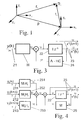
- das Einschwingverhalten des Zustandsbeobachters,
- Fig. 7:
- das Folgeverhalten des Zustandsbeobachters, dargestellt am Beispiel von zwei Quaternionen.
- Fig. 1:
- the relationship between measurement vector r 1 , target vector t 1 and position vector p,
- Fig. 2:
- a measuring principle according to the invention from controlled system 1 and condition observer 2,
- Fig. 3:
- an observation of the condition observer 2 as a filter,
- Fig. 4:
- a state observer 2 for successive measurements on three retroreflectors Ri of a target and simultaneous evaluation at the end of a cycle of measurements of all retroreflectors Ri,
- Fig. 5:
- a condition observer 2 from three sub-observers for the successive processing of the measurement results within a measurement cycle,
- Fig. 6:
- the transient response of the condition observer,
- Fig. 7:
- the subsequent behavior of the state observer, shown using the example of two quaternions.
Zur Erläuterung des erfindungsgemäßen Verfahrens sollen folgende
Randbedingungen als gegeben angenommen werden, um die Beschreibung zu
erleichtern.
Für die Funktion des erfindungsgemäßen Verfahrens ist es gleichgültig, ob sich der
Körper mit dem aktiven Sensor bewegt oder der andere Körper (im weiteren Target
genannt) mit den Retroreflektoren. Hier wird zweckmäßigerweise angenommen,
dass ein aktiver Rendezvous-Sensor auf einem bewegten Raumschiff montiert ist
und das Target (z.B. eine Raumstation oder ein anderes Raumschiff) "feststeht",
d.h. eine Bewegung des Targets ist für die relative Annäherung des Raumschiffes
ohne Bedeutung. Auf diese Weise können die ermittelten Zustandsgrößen des
Raumschiffs als Ergebnisse des erfindungsgemäßen Verfahrens direkt zur Steuerung
des bewegten Raumschiffs verwendet werden. Nachfolgend wird der aktive
Rendezvous-Sensor - ohne Beschränkung der Allgemeinheit - vereinfacht als
Laserradar bezeichnet, da ein solches bevorzugt Verwendung findet. Weiterhin wird
zur Vereinfachung der Erläuterungen die Anzahl der Retroreflektoren mit drei
angenommen, da diese in der Regel ausreicht, um eine Fläche im Raum (z.B. die
Andockfläche des anderen Körpers) exakt in Position (Entfernung) und Lage zu
definieren, wenn die Verteilung der Retroreflektoren geeignet gewählt und in ihrer
Konfiguration bekannt ist.To explain the method according to the invention, the following boundary conditions are to be assumed as given in order to facilitate the description.
For the function of the method according to the invention, it is immaterial whether the body moves with the active sensor or the other body (hereinafter referred to as the target) with the retroreflectors. It is expediently assumed here that an active rendezvous sensor is mounted on a moving spaceship and the target (eg a space station or another spaceship) is “fixed”, ie a movement of the target is irrelevant for the relative approach of the spaceship. In this way, the determined state variables of the spaceship can be used directly as results of the method according to the invention for controlling the moving spaceship. In the following, the active rendezvous sensor - without restricting generality - is referred to simply as laser radar, since it is preferably used. Furthermore, to simplify the explanations, the number of retroreflectors is assumed to be three, since this is usually sufficient to exactly define an area in space (e.g. the docking area of the other body) in terms of position (distance) and position when the distribution of the retroreflectors appropriately chosen and known in its configuration.
Fig. 1 veranschaulicht den Zusammenhang zwischen den Messdaten,
Zustandsgrößen und den unterschiedlichen Koordinatensystemen des bewegten
Körpers und des Targets, an das die Annäherung (und ggf. das Andocken) erfolgen
soll. Dabei stellt ein Messvektor r1 die eigentliche Messgröße der Entfernung bis zu
einem ersten Retroreflektor R1 dar. Der Messvektor r1 gibt im Koordinatensystem (xC,
yC, zC) des Laserradars an, wo sich der Retroreflektor R1 befindet. Ebenfalls im
Koordinatensystem (xC , yC , zC) des Laserradars wird ein Positionsvektor p
angegeben, der zum Ursprung eines Koordinatensystems (xT , yT , zT) des Targets
zeigt. Im Koordinatensystem (xT , yT , zT) des Targets werden Targetvektoren ti
angegeben, die von dessen Koordinatenursprung zu den Retroreflektoren Ri zeigen.
Zur Vereinfachung ist in Fig. 1 nur der Targetvektor t1 zum Retroreflektor R1
dargestellt. Mit einer entsprechenden Zuordnung weiterer Targetvektoren ti ist die
Anordnung der Retroreflektoren Ri im Koordinatensystem (xT, yT, zT) festgelegt.
Wenn sich die beiden oben genannten Koordinatensysteme durch einfache
Translation ineinander überführen lassen, dann gilt für den zum Retroreflektor R1
zeigenden Messvektor r1 in der Vektordarstellung gemäß Fig. 1 die einfache
Beziehung
If the two coordinate systems mentioned above can by simple translation transformed into each other, then for the pointing to the retroreflector R 1 measurement vector r 1 in the vector representation in FIG. 1, the simple relationship
Wenn die beiden Koordinatensysteme gegeneinander verdreht sind, dann muss eine
Lagematrix Q einbezogen werden. Sie gibt an, wie der Targetvektor t1, der im
Koordinatensystem (xT, yT, zT) des Targets angegeben ist, im Koordinatensystem (xC,
yC, zC) des Laserradars erscheint. Damit erhält man
Gleichung (2) zeigt, wie die Zustandsgrößen der Position mit p(x, y, z) und der Lage
mit
Q (q1, q2, q3, q4) in das Messergebnis eingehen. Dabei sind q1, q2, q3, q4
Quaternionen, die anstelle der Eulerwinkel die Lage eines Körpers in Bezug auf ein
festgelegtes Koordinatensystem beschreiben können. Quaternionen stellen neben
den Eulerwinkeln eine gleichwertige Möglichkeit dar, die Lage eines Körpers mit
körpereigenem Koordinatensystem in Bezug auf ein anderes Koordinatensystem
darzustellen. Sie haben den Vorteil, dass mit ihrer Hilfe die Lagematrix Q in
Gleichung (2) ohne Winkelfunktionen darstellbar ist. Der Einfluss der zugehörigen
Geschwindigkeiten ist durch die zeitliche Abhängigkeit gegeben und wird durch
wiederholte Messung der Retroreflektoren Ri erfasst.
Aus Gleichung (2) geht hervor, dass von den zwölf zu ermittelnde Zustandsgrößen
nur sechs Zustandsgrößen (x, y, z, q1, q2, q3) die 3 Komponenten des einzelnen
Messvektors r1 bestimmen. Deshalb muss eine bestimmte Anzahl von Messungen
gleichzeitig und zeitlich nacheinander an unterschiedlichen und gleichen
Retroreflektoren Ri durchgeführt werden, um das Informationsdefizit von nur einer
Messung auszugleichen.
Weitere Gleichungen analog zu Gleichung (2) lassen sich sinngemäß für die anderen
Retroreflektoren Ri aufstellen.Equation (2) shows how the state variables of the position with p (x, y, z) and the position with
Q (q 1 , q 2 , q 3 , q 4 ) are included in the measurement result. Here q 1 , q 2 , q 3 , q 4 are quaternions that can describe the position of a body in relation to a fixed coordinate system instead of the Euler angle. In addition to the Euler angles, quaternions represent an equivalent possibility of representing the position of a body with the body's own coordinate system in relation to another coordinate system. They have the advantage that they can be used to represent the position matrix Q in equation (2) without angular functions. The influence of the associated speeds is given by the time dependency and is recorded by repeated measurement of the retroreflectors R i .
From equation (2) it follows that of the twelve state variables to be determined, only six state variables (x, y, z, q 1 , q 2 , q 3 ) determine the 3 components of the individual measurement vector r 1 . For this reason, a certain number of measurements must be carried out simultaneously and in succession on different and identical retroreflectors R i in order to compensate for the information deficit of only one measurement.
Further equations analogous to equation (2) can be set up analogously for the other retroreflectors R i .
Das erfindungsgemäße Verfahren zur Bestimmung der genannten Zustandsgrößen,
wie in Fig. 2 dargestellt, lehnt sich an ein Prinzip der Regelungstechnik (Beobachter
von Luenberger [Föllinger, O.: Regelungstechnik, Hüthig Buch Verlag, Heidelberg,
1990, S. 501-517]) an.
Der obere Teil von Fig. 2 kann im Sinne der Regelungstechnik als eine Regelstrecke 1
(Raumschiff mit Laserradargerät) aufgefasst werden. Zu dieser gehören ein
Eingangsvektor u, eine Eingangsmatrix B, eine Systemmatrix A, ein Zustandsvektor x,
eine Ausgangsmatrix C und ein Ausgangsvektor y.
Der Eingangsvektor u, in dem die Antriebssignale und mögliche Störsignale
zusammengefasst sind, bestimmt den Zustandsvektor x des sich bewegenden
Raumschiffes über die Eingangsmatrix B. Man erkennt, dass der neue Zustand zum
Zeitpunkt (k+1) aus dem aktuellen Zustand x (k), bewertet mit der Systemmatrix A,
und aus dem aktuellen Eingangsvektor x, der mit der Eingangsmatrix B multipliziert
wird, entsteht. Ein nachfolgendes Übertragungsglied 11 mit der Einheitsmatrix I
symbolisiert durch die Operation I z-1, dass der Folgezustand x(k+1) nach einem
Abtasttakt in den aktuellen Zustandsvektor x(k) überführt wird. Im Ausgangsvektor y
sind die Messergebnisse r1, r2, r3 für die angenommenen drei Retroreflektoren R1, R2
und R3 zusammengefasst, die auf der Grundlage der aktuellen Zustandsgrößen x(k)
des sich bewegenden Raumschiffes messbar sind. Es ist zweckmäßig, die
Messergebnisse Entfernung, Azimut und Elevation in kartesische Koordinaten
umzurechnen.The method according to the invention for determining the state variables mentioned, as shown in FIG. 2, is based on a principle of control engineering (observer by Luenberger [Föllinger, O .: control engineering, Hüthig Buch Verlag, Heidelberg, 1990, pp. 501-517]) on.
The upper part of FIG. 2 can be understood as a control system 1 (spacecraft with laser radar device) in the sense of control technology. These include an input vector u, an input matrix B, a system matrix A, a state vector x, an output matrix C and an output vector y.
The input vector u, in which the drive signals and possible interference signals are combined, determines the state vector x of the moving spaceship via the input matrix B. It can be seen that the new state at the time (k + 1) from the current state x (k), evaluated with the system matrix A, and from the current input vector x, which is multiplied by the input matrix B, arises. A subsequent transmission element 11 with the unit matrix I symbolizes through operation I z -1 that the subsequent state x (k + 1) is converted into the current state vector x (k) after a sampling cycle. In the output vector y, the measurement results r 1 , r 2 , r 3 for the assumed three retroreflectors R 1 , R 2 and R 3 are summarized, which can be measured on the basis of the current state variables x (k) of the moving spaceship. It is advisable to convert the measurement results of distance, azimuth and elevation into Cartesian coordinates.
Im unteren Teil von Fig. 2 befindet sich ein Modell des bewegten Körpers, ein
sogenannter Zustandsbeobachter 2. Die Systemparameter, d.h. die Systemmatrix A
und die Ausgangsmatrix C, von der Regelstrecke 1 des bewegten Körpers und vom
Zustandsbeobachter 2 werden als gleich angenommen. Die spezielle Anpassung des
Zustandsbeobachters 2 an das Messproblem der vorgegebenen Regelstrecke 1
besteht darin, dass ein Eingangsvektor u im Zustandsbeobachter 2 nicht verwendet
wird, da er nicht zur Verfügung steht. Deshalb werden im Zustandsbeobachter 2
Schätzwerte y*(k) des Ausgangssignals erzeugt, die im Idealfall den
Messergebnissen r1, r2, r3 des Laserradars entsprechen. Da jedoch der
Eingangsvektor u im Zustandsbeobachter 2 nicht verfügbar ist, wird der nächste
Zustand aus einem aktuell geschätzten Zustandsvektor x*(k) und einer Korrektur
e(k), die die Abweichung des realen Messvektors y(k) von dem im Zustandsbeobachter
2 geschätzten Messvektor y*(k) einbezieht, berechnet. In dieser Korrektur
e(k) ist somit der Einfluss des Eingangsvektors u aus der Regelstrecke 1 mit
enthalten.
Die Erzeugung des geschätzten Messvektors y*(k) erfolgt aus dem geschätzten
Zustandsvektor x*(k) über eine Ausgangsmatrix C, die die Wirkung des realen
Zustandsvektors x(k) auf den vom Laserradar gemessenen Messvektor y(k)
beinhaltet. Die durch Differenzbildung des realen Messvektors y(k) mit dem
geschätzten Messvektor y*(k) erhaltene Korrektur e(k) wird danach über eine
Rückführmatrix H, die eine Vorschrift beinhaltet, in welchem Maße sich die
Korrektur e(k) auf den geschätzten Zustandsvektor x*(k) auswirkt, auf den aktuellen
geschätzten Zustandsvektor x*(k) angewendet, womit sich nächste geschätzte
Zustand, ein Folgezustandsvektor x*(k+1), ergibt. Das nachfolgende
Übertragungsglied 22 symbolisiert, wie schon in der Regelstrecke 1 mit 1 z-1, dass
nach einem Takt der Folgezustandsvektor x*(k+1) in den aktuellen geschätzten
Zustandsvektor x*(k) überführt wird.In the lower part of FIG. 2 there is a model of the moving body, a so-called state observer 2. The system parameters, ie the system matrix A and the output matrix C, of the controlled system 1 of the moving body and of the state observer 2 are assumed to be the same. The special adaptation of the status observer 2 to the measurement problem of the specified controlled system 1 consists in that an input vector u is not used in the status observer 2 since it is not available. Therefore, in the state observer, 2 estimates y * (k) of the output signal are generated, which ideally correspond to the measurement results r 1 , r 2 , r 3 of the laser radar. However, since the input vector u is not available in the state observer 2, the next state is made up of a currently estimated state vector x * (k) and a correction e (k), which shows the deviation of the real measurement vector y (k) from that estimated in the state observer 2 Includes measurement vector y * (k), calculated. This correction e (k) thus also includes the influence of the input vector u from the controlled system 1.
The estimated measurement vector y * (k) is generated from the estimated state vector x * (k) via an output matrix C, which contains the effect of the real state vector x (k) on the measurement vector y (k) measured by the laser radar. The correction e (k) obtained by forming the difference between the real measurement vector y (k) and the estimated measurement vector y * (k) is then via a feedback matrix H, which contains a regulation, to what extent the correction e (k) is based on the estimated State vector x * (k) affects, applied to the current estimated state vector x * (k), which results in the next estimated state, a subsequent state vector x * (k + 1). The following transmission element 22 symbolizes, as already in the controlled system 1 with 1 z -1 , that after one cycle the subsequent state vector x * (k + 1) is converted into the current estimated state vector x * (k).
Stimmt der Zustandsvektor x(k) der Regelstrecke 1 (Raumschiff) mit dem
geschätzten Zustandsvektor x*(k) des Zustandsbeobachters 2 (Rechenmodell des
Raumschiffs) überein, d.h. x(k) = x*(k), dann stimmen auch der reale Messvektor y(k)
und der vom Zustandsbeobachter 2 geschätzte Messvektor y*(k) überein. Die
Zustandsgrößen des bewegten Raumschiffes lassen sich dann direkt am Ausgang
des Zustandsbeobachters 2 ablesen.
Wenn diese Übereinstimmung nicht gegeben ist, wird mit Hilfe eines
Korrekturvektors e(k) unter Verwendung der bereits oben erwähnten
Rückführmatrix H der Zustandsvektor x*(k) des Zustandsbeobachters 2 so lange
korrigiert, bis der Fehler, d.h. die Abweichung zwischen x(k) und x*(k),
verschwindet. Dies geschieht auf Basis weiterer Abtastungen der Retroreflektoren R1
bis R3, so dass die tatsächlichen Positions- und Lageänderungen des bewegten
Körpers (Regelstrecke 1) stets direkt mit einfließen. Auf diese Weise können die
Zustandsgrößen des sich nähernden Körpers bereits nach wenigen Abtast- und
Berechnungszyklen direkt am Ausgang des Zustandsbeobachters 2 abgelesen
werden.
Bei der Nutzung der Daten aus dem Zustandsbeobachter 2 besteht in jedem Fall
auch die Option zu entscheiden, ob man von den Zuständen zweier
aufeinanderfolgender Takte den geschätzten bzw. berechneten Zustandsvektor x*(k)
oder dessen Folgezustandsvektor x*(k+1), als den am besten angenäherten Zustand
verwendet.If the state vector x (k) of the controlled system 1 (spaceship) matches the estimated state vector x * (k) of the state observer 2 (computing model of the spaceship), i.e. x (k) = x * (k), then the real measurement vector is also correct y (k) and the measurement vector y * (k) estimated by the state observer 2. The state variables of the moving spaceship can then be read directly at the output of the state observer 2.
If this correspondence does not exist, the state vector x * (k) of the state observer 2 is corrected with the aid of a correction vector e (k) using the feedback matrix H already mentioned until the error, ie the deviation between x (k) and x * (k) disappears. This is done on the basis of further scans of the retroreflectors R 1 to R 3 , so that the actual changes in position and position of the moving body (controlled system 1) are always incorporated directly. In this way, the state variables of the approaching body can be read directly at the output of the state observer 2 after only a few scanning and calculation cycles.
When using the data from the state observer 2, there is always the option to decide whether to use the estimated or calculated state vector x * (k) or its subsequent state vector x * (k + 1), as from the states of two successive cycles uses the best approximated condition.
Wenn man auf die Darstellung der Regelstrecke 1 aus Fig. 2 verzichtet, erhält man
ein in
Fig. 3 dargestelltes vereinfachtes Blockschema, das den Zusammenhang zwischen
den realen Messvektoren y(k) (Eingang 21 des Zustandsbeobachters 2) und den
geschätzten Zustandsvektoren x*(k) bzw. x*(k+1) (Ausgang 23 des
Zustandsbeobachters 2) angibt.
Die dargestellte Struktur gemäß Fig. 3 entspricht der eines digitalen Filters. Die
Eingangsgrößen dieses Filters sind die gemessenen Werte des Laserradars r1, r2, r3,
die als realer Messvektor y(k) zusammengefasst sind, und die gesuchten
Zustandsvektoren x*(k) bzw. x*(k+1) stellen die Ausgangsgrößen des als Filter
aufgebauten Zustandsbeobachters dar.If one omits the representation of the controlled system 1 from FIG. 2, one obtains a simplified block diagram shown in FIG. 3, which shows the relationship between the real measurement vectors y (k) (input 21 of the state observer 2) and the estimated state vectors x * ( k) or x * (k + 1) (output 23 of the status monitor 2).
The structure shown in FIG. 3 corresponds to that of a digital filter. The input variables of this filter are the measured values of the laser radar r 1 , r 2 , r 3 , which are combined as a real measurement vector y (k), and the sought-after state vectors x * (k) and x * (k + 1) represent the Output variables of the condition observer built as a filter.
Fig. 3 lässt erkennen, wie sich der (neue) Folgezustandsvektor x*(k+1) aus dem
aktuellen Zustandsvektor x*(k), multipliziert mit einem aus den bereits oben
eingeführten Matrizen resultierenden Operator 24, dessen Rechenvorschrift mit der
Matrizenoperation A - HC angegeben werden kann, und aus den gleichzeitig
gegebenen Messergebnissen y(k), die mit der Rückführmatrix H gewichtet werden,
ergibt.
Ein solches Filter ist dem Laserradargerät, das die Messwerte ri liefert,
nachzuschalten, um durch Auswertung der zur Auswahl stehenden
aufeinanderfolgenden Zustandsvektoren x*(k) und x*(k+1) die gesuchten
Zustandsgrößen bestimmen zu können.3 shows how the (new) sequence state vector x * (k + 1) can be derived from the current state vector x * (k), multiplied by an operator 24 resulting from the matrices already introduced above, whose calculation rule is based on the matrix operation A - HC can be specified, and results from the simultaneously given measurement results y (k), which are weighted with the feedback matrix H.
Such a filter is to be connected downstream of the laser radar device, which supplies the measured values r i , in order to be able to determine the desired state variables by evaluating the successive state vectors x * (k) and x * (k + 1).
Zum Verständnis des Operators 24 und zur Erleichterung der darauf aufbauenden
Erläuterungen der bevorzugten Ausführungsbeispiele der Erfindung sind in der
folgenden Tabelle die verwendeten Matrizen und ihre Bedeutung noch einmal
zusammengefasst.
Das dynamische Verhalten des Zustandsbeobachters 2 gemäß Fig. 2 oder 3 lässt sich
mit der Gleichung
Gleichung (3) ist gemäß Fig. 3 direkt anwendbar, wenn zum Beispiel mit drei
Laserstrahlen die Positionen und Lagen der drei Retroreflektoren R1, R2 und R3
gleichzeitig gemessen werden. In diesem Falle hat der Ausgangsvektor die Form
y = (r1' r2' r3')', wobei das Apostroph jeweils den transponierten Vektor bedeutet.
Das ist normalerweise ein zu hoher technischer Aufwand. Aus diesem Grunde
möchte man die Messung der drei (oder mehr) Retroreflektoren Ri mit einem
Laserradar zeitlich nacheinander ausführen. Equation (3) according to FIG. 3 is directly applicable if, for example, the positions and positions of the three retroreflectors R 1 , R 2 and R 3 are measured simultaneously with three laser beams. In this case the output vector has the form y = (r 1 'r 2 ' r 3 ')', the apostrophe each meaning the transposed vector.
This is usually too much technical effort. For this reason, one would like to measure the three (or more) retroreflectors R i with a laser radar one after the other.
Die Vorgehensweise nach Fig. 2 oder 3 kann für eine volumen- und gewichtsorientierte Lösung der erfindungsgemäßen Aufgabe nicht unmittelbar verwendet werden, da
- die Abtastung der Retroreflektoren Ri (i = 1, 2,..., n; n ≥ 3) zeitlich nacheinander erfolgt und damit das zeitdiskrete System zwei Abtastfrequenzen besitzt, eine Messtaktfrequenz fP der seriellen Abtastung der Retroreflektoren Ri und eine Zyklustaktfrequenz der Berechnung der Zustandsvektoren, die beide über die Zahl n der benutzten Retroreflektoren Ri zusammenhängen, fP = n fc;
- sich die Retroreflektoren Ri an unterschiedlichen Positionen befinden und damit die Ausgangsmatrizen Ci für die n Retroreflektoren Ri unterschiedlich sind;
- zu jedem der Retroreflektoren Ri eine passende Rückführmatrix Hi gewählt werden muss und
- die Eigenwerte des Zustandsbeobachters 2 je nach dem Betriebsmode des Laserradars einzustellen sind.
- the scanning of the retroreflectors R i (i = 1, 2, ..., n; n ≥ 3) takes place successively in time and thus the discrete-time system has two sampling frequencies, a measuring clock frequency f P of the serial scanning of the retroreflectors R i and a cycle clock frequency of Calculation of the state vectors, both of which are related to the number n of retroreflectors R i used , f P = nf c ;
- the retroreflectors R i are at different positions and the output matrices C i for the n retroreflectors R i are different;
- a suitable feedback matrix H i must be selected for each of the retroreflectors R i and
- the eigenvalues of the status monitor 2 are to be set depending on the operating mode of the laser radar.
In der Phase größerer Entfernung sind die Zustandsgrößen mit geringerer Genauigkeit zu messen, der Zustandsbeobachter 2 muss schneller einschwingen können, d.h. die geschätzten Messvektoren y*(k) müssen schneller an die realen Messvektoren y(k) angenähert werden. In unmittelbarer Nähe des Andockvorganges ist die Annäherungsgeschwindigkeit klein und es ist deshalb sinnvoll, den Zustandsbeobachter 2 träger zu dimensionieren, damit man durch eine wirksame Mittelwertbildung eine höhere Genauigkeit erhält.In the phase of greater distance, the state variables are smaller To measure accuracy, the condition observer 2 must settle faster can, i.e. the estimated measurement vectors y * (k) must match the real ones more quickly Measurement vectors y (k) can be approximated. In the immediate vicinity of the docking process the approach speed is low and it is therefore advisable to Condition observers to dimension 2 carriers, so that one through an effective Averaging receives a higher accuracy.
Für die Anwendung linearer Zusammenhänge zwischen dem realen Zustandsvektor
x(k) des bewegten Körpers (Regelstrecke 1), auf dem sich das Laserradargerät
befindet, und dem Messvektor y(k) = (r1' r2' r3')' wird vorausgesetzt, dass die
Eulerwinkel, die die relative Lage der zwei sich annähernden Körper zueinander
beschreiben, klein genug (<10°) sind. Andernfalls müsste der Messvektor y(k)
nichtlineare Funktionen in Abhängigkeit vom Zustandsvektors x(k) enthalten, was
prinzipiell problemlos möglich und für bestimmte Anwendungen zu berücksichtigen
ist.
Ausgehend von der obigen Gleichung (3) wird das Prinzip des Zustandsbeobachters
2 bei drei zeitlich nacheinander abzutastenden Retroreflektoren R1, R2, R3 auf
folgende Weise abgeändert:

Starting from equation (3) above, the principle of the state observer 2 is modified in the following way for three retroreflectors R 1 , R 2 , R 3 to be scanned in time:
Im einem ersten Abschnitt des Zyklustaktes, Δ = 1/3, wird auf der Grundlage eines Anfangswertes x*(0) des zu schätzenden Zustandsvektors x*(k) unter Verwendung des Messergebnisses y1(k) = r1 am Retroreflektor R1 ein neuer Schätzwert berechnet. Dieser resultierende geschätzte Zustandsvektor x*(k+Δ) wird mit Hilfe der nächsten Messung y2(k+Δ) = r2 am Retroreflektor R2 verbessert, und man erhält x*(k+2Δ). Schließlich wird im dritten und letzten Abschnitt des Zyklustaktes unter Verwendung des Messergebnisses y3(k+2Δ) = r3 vom Retroreflektor R3 ein weiterer Schätzwert x*(k+3Δ) als neuer Zustandsvektor x*(k+1) bestimmt. Damit beginnt der nächste Zyklus der soeben beschriebenen drei Zyklusabschnitte.In a first section of the cycle clock, Δ = 1/3, on the basis of an initial value x * (0) of the state vector to be estimated x * (k) using the measurement result y 1 (k) = r 1 on the retroreflector R 1 new estimate calculated. This resulting estimated state vector x * (k + Δ) is improved with the aid of the next measurement y 2 (k + Δ) = r 2 at the retroreflector R 2 , and x * (k + 2Δ) is obtained. Finally, in the third and last section of the cycle cycle, using the measurement result y 3 (k + 2Δ) = r 3, the retroreflector R 3 determines a further estimate x * (k + 3Δ) as the new state vector x * (k + 1). This starts the next cycle of the three cycle sections just described.
Aus dem Gleichungssystem (4) geht hervor, dass
- für jeden Retroreflektor R1, R2, R3 eine eigene Ausgangsmatrix C1, C2, C3 gilt;
- für jede Ausgangsmatrix C1, C2, C3 die passende Rückführmatrix H1, H2, H3 zu bestimmen ist;
- eine Systemmatrix A5 notwendig ist, die zum Taktabschnitt Δ = 1/3fc gehört, wobei der Faktor 3 im Nenner aus der Anzahl n=3 der Retroreflektoren Ri resultiert;
- das Eigenverhalten und damit die Konvergenz des Zustandsbeobachters 2 durch die Matrizen C1, C2, C3, H1, H2, H3 und AS bestimmt wird und
- zu jedem Messtakt der aktualisierte Schätzwert des Zustandvektors x* verfügbar ist.
- a separate output matrix C 1 , C 2 , C 3 applies to each retroreflector R 1 , R 2 , R 3 ;
- the appropriate feedback matrix H 1 , H 2 , H 3 is to be determined for each output matrix C 1 , C 2 , C 3 ;
- a system matrix A 5 is necessary, which belongs to the clock segment Δ = 1 / 3f c , the factor 3 in the denominator resulting from the number n = 3 of the retroreflectors R i ;
- the behavior and thus the convergence of the condition observer 2 is determined by the matrices C 1 , C 2 , C 3 , H 1 , H 2 , H 3 and A S and
- the updated estimate of the state vector x * is available for each measuring cycle.
Aus den oben angegebenen Gleichungen kann man eine von Fig. 3 abgeleitete Filterstruktur ermitteln, die in Fig. 4 dargestellt ist. Dabei bedeuten
- die Matrix 25 eine resultierende Systemmatrix M des Zustandsbeobachters 2,
deren Eigenwerte die Stabilität und Konvergenz des simulierten
Annäherungsprozesses des bewegten Körpers bestimmen, mit
- die Bewertungsoperatoren 251, 252 und 253 eine spezielle Wichtung für jeden der zeitlich getaktet an separaten Eingängen 211, 212 und 213 ankommenden Messvektoren y1, y2 und y3.
- the matrix 25 also includes a resulting system matrix M of the state observer 2, the eigenvalues of which determine the stability and convergence of the simulated approximation process of the moving body
- the evaluation operators 251, 252 and 253 assign a special weighting for each of the measurement vectors y 1 , y 2 and y 3 arriving at separate inputs 211, 212 and 213.
Dabei enthalten die Bewertungsoperatoren 251, 252, 253
- Bewertungsmatrizen Mi, die die unterschiedlichen Zeitpunkte (..., k, k+Δ, k+2Δ,
k+3Δ = k+1,...) und damit die Aktualität der Messvektoren yi berücksichtigen, mit
und

- Rückführmatrizen H1, H2, H3, die angeben,welchen Einfluss die Messvektoren y1, y2, y3 auf die Korrektur des Zustandsvektors x* haben.
- Evaluation matrices M i , which take into account the different points in time (..., k, k + Δ, k + 2Δ, k + 3Δ = k + 1, ...) and thus the up-to-dateness of the measurement vectors y i and
- Feedback matrices H 1 , H 2 , H 3 , which indicate the influence that the measurement vectors y 1 , y 2 , y 3 have on the correction of the state vector x *.
Das Schema gemäß Fig. 4 zur Realisierung dieser Filterstruktur arbeitet mit der Zyklustaktfrequenz fc, die im Falle von drei Retroreflektoren der dreifachen Messtaktfrequenz fP des Laserradargerätes (fc = 3fP) entspricht. Die Filterstruktur enthält somit einstellbare Systemparameter, die angeben,
- wie mit Hilfe der Matrix 25 das Einschwingverhalten, die Dynamik, des Zustandsbeobachters 2 festgelegt werden kann und
- wie die zeitliche Aufeinanderfolge der Messvektoren yi zum Zustandsvektor x* am Ausgang 23 des Zustandsbeobachters 2 beiträgt.
- how the transient response, the dynamics of the condition monitor 2 can be determined with the aid of the matrix 25 and
- how the chronological sequence of the measurement vectors y i contributes to the state vector x * at the output 23 of the state observer 2.
In Fig. 5 ist der Zustandsbeobachter 2 nach dem Gleichungssystem (4) in Form einer
Programmschleife 26 dargestellt. Diese zeigt im Unterschied zu Fig. 4, dass nach
jedem Messtakt genau ein aktualisierter Zustandsvektor x* verfügbar ist. Auch in
diesem Beispiel werden drei Retroreflektoren R1, R2, R3 verwendet. Die Bedingungen
für einen linearen Zustandsbeobachter 2 (kleine Eulerwinkel) sollen erfüllt sein.
Wenn man mit dem Startwert x*(0) beginnt, berechnet man nach der Gleichung im
ersten Block 261 unter Verwendung von y1(k), k = 0, den ersten aktualisierten
Zustandsvektor x*(k+Δ), k = 0, als Ergebnis des ersten Messtaktes. Mit diesem
Zustandsvektor x*(k+Δ) und der Messung y2(k+Δ), k = 0, wird die Anweisung des
zweiten Blockes 262 ausgeführt. In analoger Weise wird der dritte Block 263
bearbeitet und damit der erste Zyklus beendet. Man erhält den Schätzwert x*(k=1).
Dieser Schätzwert wird als Startwert für den nächsten Zyklus verwendet, bei dem
jetzt k = 1 gilt. In dieser Folge werden die weiteren Messungen [Messvektoren yi(k)]
zur Schätzung des jeweils nächsten Folgezustandsvektors x*(k+1) des bewegten
Raumschiffes benutzt.5 shows the state observer 2 according to the system of equations (4) in the form of a program loop 26. In contrast to FIG. 4, this shows that exactly one updated state vector x * is available after each measuring cycle. Three retroreflectors R 1 , R 2 , R 3 are also used in this example. The conditions for a linear state observer 2 (small Euler angles) should be met.
If one starts with the starting value x * (0), the first updated state vector x * (k + Δ), k = 0, is calculated according to the equation in the first block 261 using y 1 (k), k = 0, as a result of the first measurement cycle. With this state vector x * (k + Δ) and the measurement y 2 (k + Δ), k = 0, the instruction of the second block 262 is carried out. The third block 263 is processed in an analogous manner and the first cycle is thus ended. The estimate x * (k = 1) is obtained. This estimate is used as the starting value for the next cycle, where k = 1 now applies. In this sequence, the further measurements [measurement vectors y i (k)] are used to estimate the next sequence state vector x * (k + 1) of the moving spaceship.
Die zuverlässige Funktionsweise des Verfahrens gemäß Fig. 5 hängt wesentlich von der Dimensionierung der verwendeten Matrizen ab:
- Die Systemmatrix As beschreibt den Zusammenhang der Zustandsgrößen zwischen zwei aufeinderfolgenden Zeitpunkten, wenn keine weiteren Messvektoren yi an den Eingängen 211, 212, 213 wirken (sogenanntes autonomes System).
- Die Ausgangsmatrizen C1, C2, C3 geben den Zusammenhang zwischen den Zustandsgrößen und den drei Komponenten des realen Zustandsvektors x(k) bzw. des berechneten Zustandsvektors x*(k) vom Koordinatenursprung des Laserradargerätes zum betreffenden Retroreflektor R1, R2 oder R3 an.
- Die Matrizen H1, H2, H3 sind geeignet dimensionierte Bewertungsmatrizen. Sie bestimmen, wie die Abweichung zwischen dem gemessenen y(k) und dem im Zustandsbeobachter 2 geschätzten Messvektor y*(k) zur Korrektur des geschätzten Zustandsvektors x*(k) benutzt wird.
- The system matrix A s describes the relationship between the state variables between two successive points in time when no further measurement vectors y i act on the inputs 211, 212, 213 (so-called autonomous system).
- The output matrices C 1 , C 2 , C 3 give the relationship between the state variables and the three components of the real state vector x (k) or the calculated state vector x * (k) from the coordinate origin of the laser radar device to the relevant retroreflector R 1 , R 2 or R 3 on.
- The matrices H 1 , H 2 , H 3 are suitably dimensioned evaluation matrices. They determine how the deviation between the measured y (k) and the measurement vector y * (k) estimated in the state observer 2 is used to correct the estimated state vector x * (k).
Nach etwa drei Zyklen, d.h. drei Durchläufen der Regelschleife 26 unter sukzessiver Einbeziehung der durch die geordnete Abtastung der Retroreflektoren R1, R2 und R3 aufeinanderfolgend bereitgestellten Messvektoren y1, y2, y3 kann man die Zustandsgrößen des bewegten Körpers mit für viele Fälle ausreichender Genauigkeit gewinnen. Ein weiterer Vorteil dieser Variante des erfindungsgemäßen Verfahrens besteht darin, dass aus den geschätzten Zustandsgrößen auch die ungefähre Lage des nächsten Retroreflektors Ri berechnet werden kann, was eine Verbesserung des Messvorganges durch geeignete Auswahl des Gesichtsfeldes des Laserradars bedeutet.After about three cycles, that is to say three passes through the control loop 26, with successive inclusion of the measurement vectors y 1 , y 2 , y 3 provided successively by the orderly scanning of the retroreflectors R 1 , R 2 and R 3 , the state variables of the moving body can be used for many Win cases of sufficient accuracy. Another advantage of this variant of the method according to the invention is that the approximate position of the next retroreflector R i can also be calculated from the estimated state variables, which means an improvement of the measurement process by suitable selection of the field of view of the laser radar.
Fig. 6 zeigt für das letzte Beispiel der sukzessiven Verarbeitung der Messvektoren yi den Einschwingvorgang des Zustandsbeobachters 2. Im Startzeitpunkt der Messung haben Raumschiff und Zustandsbeobachter 2 unterschiedliche Anfangsbedingungen. Nach etwa drei Zyklen zu je drei Takten ist der Fehler der Zustandsvektoren x*(k) - x(k) nahezu Null. In diesem Beispiel wird dies besonders deutlich bei dem Quaternion q1, der zugehörigen Winkelgeschwindigkeit und der translatorischen Geschwindigkeit in x-Richtung. Die übrigen Kurven stellen die Abweichungen der anderen Zustandsgrößen dar.6 shows the settling process of the state observer 2 for the last example of the successive processing of the measurement vectors y i . At the start of the measurement, the spacecraft and the state observer 2 have different initial conditions. After about three cycles of three cycles, the error of the state vectors x * (k) - x (k) is almost zero. In this example, this becomes particularly clear with the quaternion q 1 , the associated angular velocity and the translatory velocity in the x direction. The other curves represent the deviations of the other state variables.
In Fig. 7 ist dargestellt, in welcher Weise der Zustandsbeobachter gemäß Fig. 5 den
sich ändernden Zustandsgrößen des bewegten Raumschiffes folgt. Wenn sich
beispielsweise das Quaternion q1 (entspricht dem Rollwinkel) nahezu sprungartig
ändert, dann folgt der Zustandsbeobachter in relativ kurzer Zeit mit einem
Überschwingen. Gleichzeitig verändert sich das Quaternion q2 (entspricht dem
Nickwinkel) etwa sinusförmig, und der Zustandsbeobachter kann sehr genau folgen.
Der vom Zustandsbeobachter erzeugte Schätzwert für das Quaternion q2* ist
praktisch gleich dem realen Wert q2. Nahezu gleiches Verhalten zeigen ebenfalls die
anderen Zustandsgrößen, wodurch die Leistungsfähigkeit der letzten Variante des
erfindungsgemäßen Verfahrens eindrucksvoll nachgewiesen wird.
Ähnliche Resultate ergeben sich aber auch für die Grundvariante der Erfindung. Dies
gilt ebenfalls in der Ausführung nach Fig. 4, bei der - aufgrund der Notwendigkeit
einer jeweils vollständigen Serie von Retroreflektorabtastungen - das Folgeverhalten
des Zustandsbeobachters lediglich ein gröberes Zeitraster bei der Ausgabe der
Zustandsgrößen aufweist. FIG. 7 shows the manner in which the state observer according to FIG. 5 follows the changing state variables of the moving spaceship. If, for example, the quaternion q 1 (corresponds to the roll angle) changes almost suddenly, the condition observer follows in a relatively short time with an overshoot. At the same time, the quaternion q 2 (corresponds to the pitch angle) changes approximately sinusoidally, and the condition observer can follow very precisely. The estimate of the quaternion q 2 * generated by the state observer is practically equal to the real value q 2 . The other state variables also show almost the same behavior, as a result of which the performance of the last variant of the method according to the invention is impressively demonstrated.
Similar results are also obtained for the basic variant of the invention. This also applies in the embodiment according to FIG. 4, in which - due to the necessity of a complete series of retroreflector scans in each case - the subsequent behavior of the state observer only has a coarser time grid when the state variables are output.
- 11
- Regelstrecke (Raumschiff)Controlled system (spaceship)
- 1111
- Übertragungsgliedtransmission member
- 22
- Zustandsbeobachterstate observer
- 2121
- Eingangentrance
- 211, 212, 213211, 212, 213
- getaktete Eingängeclocked inputs
- 2222
- ÜbertraqunqsqliedÜbertraqunqsqlied
- 2323
- Ausgangoutput
- 2424
- Operator (A - HC)Operator (A - HC)
- 2525
- Matrix MMatrix M
- 251, 252, 253251, 252, 253
- Bewertungsoperatoren (MiHi)Evaluation operators (M i H i )
- 2626
- Regelschleifecontrol loop
- 261, 262, 263261, 262, 263
- Blockblock
- AA
- Systemmatrixmatrix
- BB
- Eingangsmatrixinput matrix
- cc
- Ausgangsmatrixoutput matrix
- HH
- RückführmatrixFeedback matrix
- R1 R 1
- Retroreflektorenretroreflectors
- p1 p 1
- Positionsvektorposition vector
- q1, q2 ···q 1 , q 2 ···
- Quaternionenquaternions
- r1 r 1
- Messvektor (zum Retroreflektor R1)Measurement vector (to retroreflector R 1 )
- t1 t 1
- Targetvektortarget vector
- (xc,yc,zc)(x c , y c , z c )
- Koordinatensystem (des bewegten Körpers)Coordinate system (of the moving body)
- (xT, yT, zT)(x T , y T , z T )
- Koordinatensystem (des Targets)Coordinate system (of the target)
- xx
- realer Zustandsvektorreal state vector
- x*(k)x * (k)
- geschätzter(berechneter) Zustandsvektorestimated (calculated) state vector
- x*(k+1)x * (k + 1)
- FolgezustandsvektorSubsequent state vector
- y,/y*y / y *
- realer/ geschätzter Messvektorreal / estimated measurement vector
Claims (10)
Applications Claiming Priority (2)
| Application Number | Priority Date | Filing Date | Title |
|---|---|---|---|
| DE10011890A DE10011890C2 (en) | 2000-03-03 | 2000-03-03 | Method for determining the state variables of a moving rigid body in space |
| DE10011890 | 2000-03-03 |
Publications (1)
| Publication Number | Publication Date |
|---|---|
| EP1129944A1 true EP1129944A1 (en) | 2001-09-05 |
Family
ID=7634344
Family Applications (1)
| Application Number | Title | Priority Date | Filing Date |
|---|---|---|---|
| EP01104452A Withdrawn EP1129944A1 (en) | 2000-03-03 | 2001-02-28 | State of a moving body ( docking, rendezvous ) with three retro reflectors and state observer ( Luenberger ) |
Country Status (4)
| Country | Link |
|---|---|
| US (1) | US20010037185A1 (en) |
| EP (1) | EP1129944A1 (en) |
| JP (1) | JP2001315698A (en) |
| DE (1) | DE10011890C2 (en) |
Cited By (3)
| Publication number | Priority date | Publication date | Assignee | Title |
|---|---|---|---|---|
| WO2005045784A1 (en) * | 2003-10-31 | 2005-05-19 | Conti Temic Microelectronic Gmbh | Method and device for measuring distance and/or speed |
| WO2016116856A1 (en) * | 2015-01-20 | 2016-07-28 | Politecnico Di Torino | Method and system for measuring the angular velocity of a body orbiting in space |
| CN113443555A (en) * | 2021-06-24 | 2021-09-28 | 上海振华重工(集团)股份有限公司 | Method for determining position of grab bucket, method for detecting position of grab bucket and storage medium |
Families Citing this family (13)
| Publication number | Priority date | Publication date | Assignee | Title |
|---|---|---|---|---|
| DE10034869A1 (en) * | 2000-07-18 | 2002-02-07 | Siemens Ag | Method for automatically obtaining a functional sequence of processes and tools for this |
| US7230689B2 (en) * | 2002-08-26 | 2007-06-12 | Lau Kam C | Multi-dimensional measuring system |
| US7602480B2 (en) * | 2005-10-26 | 2009-10-13 | Alcatel-Lucent Usa Inc. | Method and system for tracking a moving station or target in free space communications |
| DE102012000331B4 (en) | 2012-01-11 | 2018-08-16 | Jena-Optronik Gmbh | Method and sensor system for determining the position of a flying object |
| DE102012111752A1 (en) * | 2012-12-04 | 2014-06-18 | Jena-Optronik Gmbh | Method for automatic correction of alignment errors in star sensor systems |
| KR102529171B1 (en) * | 2016-02-26 | 2023-05-04 | 삼성전자주식회사 | Memory device diagnosis system |
| CN109094818B (en) * | 2018-01-24 | 2021-01-22 | 北京电子工程总体研究所 | Remote rendezvous guidance method for spacecraft |
| CN108762495B (en) * | 2018-05-18 | 2021-06-29 | 深圳大学 | Virtual reality driving method based on arm motion capture and virtual reality system |
| EP3610993A1 (en) * | 2018-08-14 | 2020-02-19 | Beckman Coulter, Inc. | System for active motion displacement control of a robot |
| CN109814583B (en) * | 2019-01-18 | 2021-08-31 | 东华理工大学 | Dynamic state feedback control method based on autonomous underwater robot course motion |
| CN110492815B (en) * | 2019-08-23 | 2021-02-02 | 哈尔滨工业大学 | Synchronous optimization method for stability and dynamic performance of extremely low speed of sensorless induction motor |
| CN111531407B (en) * | 2020-05-08 | 2021-08-17 | 太原理工大学 | Workpiece attitude rapid measurement method based on image processing |
| CN112363522B (en) * | 2020-11-09 | 2022-09-27 | 西北工业大学 | Networked spacecraft attitude control method based on hybrid forced observer |
Citations (6)
| Publication number | Priority date | Publication date | Assignee | Title |
|---|---|---|---|---|
| US4521855A (en) * | 1981-07-27 | 1985-06-04 | Ford Aerospace & Communications Corporation | Electronic on-orbit roll/yaw satellite control |
| US4834531A (en) * | 1985-10-31 | 1989-05-30 | Energy Optics, Incorporated | Dead reckoning optoelectronic intelligent docking system |
| US5020876A (en) * | 1990-02-20 | 1991-06-04 | The United States Of America As Represented By The Administrator Of The National Aeronautics And Space Administration | Standard remote manipulator system docking target augmentation for automated docking |
| US5109345A (en) * | 1990-02-20 | 1992-04-28 | The United States Of America As Represented By The Administrator Of The National Aeronautics And Space Administration | Closed-loop autonomous docking system |
| US5436841A (en) * | 1992-03-16 | 1995-07-25 | Aerospatiale Societe Nationale Industrielle | Method and device for determining the relative position and the relative path of two space vehicles |
| DE19515176A1 (en) * | 1994-06-17 | 1995-12-21 | Trw Inc | Autonomous rendevous and docking system for space vehicles |
Family Cites Families (2)
| Publication number | Priority date | Publication date | Assignee | Title |
|---|---|---|---|---|
| JP2669223B2 (en) * | 1991-10-14 | 1997-10-27 | 三菱電機株式会社 | Optical sensor device for rendezvous docking |
| US5334848A (en) * | 1993-04-09 | 1994-08-02 | Trw Inc. | Spacecraft docking sensor system |
-
2000
- 2000-03-03 DE DE10011890A patent/DE10011890C2/en not_active Expired - Fee Related
-
2001
- 2001-02-28 EP EP01104452A patent/EP1129944A1/en not_active Withdrawn
- 2001-03-02 US US09/798,556 patent/US20010037185A1/en not_active Abandoned
- 2001-03-02 JP JP2001058386A patent/JP2001315698A/en active Pending
Patent Citations (6)
| Publication number | Priority date | Publication date | Assignee | Title |
|---|---|---|---|---|
| US4521855A (en) * | 1981-07-27 | 1985-06-04 | Ford Aerospace & Communications Corporation | Electronic on-orbit roll/yaw satellite control |
| US4834531A (en) * | 1985-10-31 | 1989-05-30 | Energy Optics, Incorporated | Dead reckoning optoelectronic intelligent docking system |
| US5020876A (en) * | 1990-02-20 | 1991-06-04 | The United States Of America As Represented By The Administrator Of The National Aeronautics And Space Administration | Standard remote manipulator system docking target augmentation for automated docking |
| US5109345A (en) * | 1990-02-20 | 1992-04-28 | The United States Of America As Represented By The Administrator Of The National Aeronautics And Space Administration | Closed-loop autonomous docking system |
| US5436841A (en) * | 1992-03-16 | 1995-07-25 | Aerospatiale Societe Nationale Industrielle | Method and device for determining the relative position and the relative path of two space vehicles |
| DE19515176A1 (en) * | 1994-06-17 | 1995-12-21 | Trw Inc | Autonomous rendevous and docking system for space vehicles |
Cited By (4)
| Publication number | Priority date | Publication date | Assignee | Title |
|---|---|---|---|---|
| WO2005045784A1 (en) * | 2003-10-31 | 2005-05-19 | Conti Temic Microelectronic Gmbh | Method and device for measuring distance and/or speed |
| WO2016116856A1 (en) * | 2015-01-20 | 2016-07-28 | Politecnico Di Torino | Method and system for measuring the angular velocity of a body orbiting in space |
| CN113443555A (en) * | 2021-06-24 | 2021-09-28 | 上海振华重工(集团)股份有限公司 | Method for determining position of grab bucket, method for detecting position of grab bucket and storage medium |
| CN113443555B (en) * | 2021-06-24 | 2023-11-24 | 上海振华重工(集团)股份有限公司 | Method for determining grab bucket position, grab bucket position detection method and storage medium |
Also Published As
| Publication number | Publication date |
|---|---|
| DE10011890A1 (en) | 2001-09-13 |
| US20010037185A1 (en) | 2001-11-01 |
| JP2001315698A (en) | 2001-11-13 |
| DE10011890C2 (en) | 2003-04-24 |
Similar Documents
| Publication | Publication Date | Title |
|---|---|---|
| DE10011890C2 (en) | Method for determining the state variables of a moving rigid body in space | |
| DE3427020C2 (en) | ||
| EP3407090A1 (en) | Method for detecting and autonomous tracking of a target object by means of a lidar sensor | |
| EP0762247B1 (en) | Coordinate measuring machine with a controller that moves the probe of the measuring apparatus in accordance with reference date | |
| WO1993004923A1 (en) | Measurement arrangement useful for controlling the attitude of a three-axis stabilized satellite, corresponding evaluation process, regulating system and process | |
| WO1989002622A1 (en) | Device for regulating a set value and/or for stabilizing freely moving objects with stored spin | |
| DE102018104090A1 (en) | ADAPTIVE DESCRIPTION OF PROCESS RUSTS FOR IMPROVED KALMAN FILTER TARGET TRACKING | |
| EP1927866A1 (en) | Method for grid-based processing of sensor signals | |
| DE102014103370A1 (en) | Method and device for discrete-time control of a manipulator | |
| EP1094002A2 (en) | Satellite control system and method | |
| DE19841716A1 (en) | Movement guidance control for industrial processing machine | |
| DE102007007266B4 (en) | Method for evaluating sensor measured values | |
| EP3746850A1 (en) | Method for ascertaining a time characteristic of a measured variable, prediction system, actuator control system, method for training the actuator control system, training system, computer program and machine-readable storage medium | |
| DE4218599C2 (en) | Navigation and guidance system for autonomous, mobile robots | |
| DE19645556A1 (en) | Steering signal generating device for target tracking of e.g. military missile | |
| EP1515159B1 (en) | Method for reducing the doppler centroid for coherent pulsed radar system | |
| EP0207521B1 (en) | Target measurement system | |
| DE10130623C1 (en) | Method for determining the state variables of a rigid body in space using a videometer | |
| EP3628964B1 (en) | Opto-electro-mechanical beam manipulation system | |
| EP1440289B1 (en) | Navigation system for determining the course of a vehicle | |
| WO2021099452A1 (en) | Calibration of an impedance control of a robot manipulator | |
| EP0452797A2 (en) | Kalman filter | |
| EP1186908A2 (en) | Method of tracking a moving target | |
| EP3404364B1 (en) | Method for estimating a condition of a mobile platform | |
| EP0733546A1 (en) | Three axis stabilized spacecraft and method of sun acquisition |
Legal Events
| Date | Code | Title | Description |
|---|---|---|---|
| PUAI | Public reference made under article 153(3) epc to a published international application that has entered the european phase |
Free format text: ORIGINAL CODE: 0009012 |
|
| AK | Designated contracting states |
Kind code of ref document: A1 Designated state(s): FR GB IT Kind code of ref document: A1 Designated state(s): AT BE CH CY DE DK ES FI FR GB GR IE IT LI LU MC NL PT SE TR |
|
| AX | Request for extension of the european patent |
Free format text: AL;LT;LV;MK;RO;SI |
|
| 17P | Request for examination filed |
Effective date: 20020226 |
|
| AKX | Designation fees paid |
Free format text: FR GB IT |
|
| REG | Reference to a national code |
Ref country code: DE Ref legal event code: 8566 |
|
| STAA | Information on the status of an ep patent application or granted ep patent |
Free format text: STATUS: THE APPLICATION IS DEEMED TO BE WITHDRAWN |
|
| 18D | Application deemed to be withdrawn |
Effective date: 20030902 |