EP1129846A1 - Ink jet plate maker and proofer apparatus and method - Google Patents
Ink jet plate maker and proofer apparatus and method Download PDFInfo
- Publication number
- EP1129846A1 EP1129846A1 EP01200574A EP01200574A EP1129846A1 EP 1129846 A1 EP1129846 A1 EP 1129846A1 EP 01200574 A EP01200574 A EP 01200574A EP 01200574 A EP01200574 A EP 01200574A EP 1129846 A1 EP1129846 A1 EP 1129846A1
- Authority
- EP
- European Patent Office
- Prior art keywords
- printing
- print head
- printing plate
- drops
- predetermined volume
- Prior art date
- Legal status (The legal status is an assumption and is not a legal conclusion. Google has not performed a legal analysis and makes no representation as to the accuracy of the status listed.)
- Granted
Links
Images


Classifications
-
- B—PERFORMING OPERATIONS; TRANSPORTING
- B41—PRINTING; LINING MACHINES; TYPEWRITERS; STAMPS
- B41J—TYPEWRITERS; SELECTIVE PRINTING MECHANISMS, i.e. MECHANISMS PRINTING OTHERWISE THAN FROM A FORME; CORRECTION OF TYPOGRAPHICAL ERRORS
- B41J2/00—Typewriters or selective printing mechanisms characterised by the printing or marking process for which they are designed
- B41J2/005—Typewriters or selective printing mechanisms characterised by the printing or marking process for which they are designed characterised by bringing liquid or particles selectively into contact with a printing material
- B41J2/01—Ink jet
- B41J2/17—Ink jet characterised by ink handling
- B41J2/175—Ink supply systems ; Circuit parts therefor
-
- B—PERFORMING OPERATIONS; TRANSPORTING
- B41—PRINTING; LINING MACHINES; TYPEWRITERS; STAMPS
- B41C—PROCESSES FOR THE MANUFACTURE OR REPRODUCTION OF PRINTING SURFACES
- B41C1/00—Forme preparation
- B41C1/10—Forme preparation for lithographic printing; Master sheets for transferring a lithographic image to the forme
- B41C1/1066—Forme preparation for lithographic printing; Master sheets for transferring a lithographic image to the forme by spraying with powders, by using a nozzle, e.g. an ink jet system, by fusing a previously coated powder, e.g. with a laser
-
- B—PERFORMING OPERATIONS; TRANSPORTING
- B41—PRINTING; LINING MACHINES; TYPEWRITERS; STAMPS
- B41J—TYPEWRITERS; SELECTIVE PRINTING MECHANISMS, i.e. MECHANISMS PRINTING OTHERWISE THAN FROM A FORME; CORRECTION OF TYPOGRAPHICAL ERRORS
- B41J2/00—Typewriters or selective printing mechanisms characterised by the printing or marking process for which they are designed
- B41J2/005—Typewriters or selective printing mechanisms characterised by the printing or marking process for which they are designed characterised by bringing liquid or particles selectively into contact with a printing material
- B41J2/01—Ink jet
- B41J2/015—Ink jet characterised by the jet generation process
- B41J2/04—Ink jet characterised by the jet generation process generating single droplets or particles on demand
Definitions
- the present invention relates to an ink jet printer apparatus and method, and more particularly, to an ink jet printer and method for making a printing plate and a proof of a work such as text and/or an image to be printed by the printing plate.
- a printing plate for a work is typically made, and then one or more proofs of the work are printed using the printing plate to allow determining desirability and accuracy of the printed image before a large number of prints are printed.
- the proofing activity might take several stages: an initial, creative stage in which a computer display might be adequate for proofing; an intermediate stage in which a desktop-type inkjet or thermal printer output might be used; and a final, more critical stage in which an accurate picture of the final plate result, including the micro-structure of the halftone dots to be produced on the plate, is desired. It is toward this last need for an accurate halftone proofer, matched to a corresponding platemaker, that the present invention is directed.
- Fromson et al. U.S. Patent No. 5,750,314 issued May 12, 1998 which discloses a method for selectively imaging a lithographic printing plate using an ink jet printer.
- a substrate is coated with a first material, which is soluble in a first solvent, whereupon a second material, which strongly adheres to the first material and insoluble in the first solvent, is selectively applied by an ink jet printer.
- the substrate is then developed in the first solvent to establish the image.
- Fromson et al. does not disclose a method or apparatus for producing a proof of a work to be printed, without first requiring making the printing plate.
- an object of the present invention is to provide an ink jet printer and method for printing an accurate proof of a work to be printed using a printing plate without first requiring making the printing plate, and for making the printing plate.
- the ink jet printer includes a first print head connected in fluid communication with a source of ink for printing the proof of the work, and a second print head in fluid communication with a source of a liquid for making the printing plate, the print heads being disposed for ejecting drops of the ink and the liquid image wise onto a proofing receiver and a treated plate, respectively, positionable on a platen relatively moveable with respect to the print heads.
- the first element is connected in electrical communication with the first print head and includes a first clock connected to a signal generator operable for producing a drive signal for driving the print head for generating the ink drops of the first predetermined volume for printing the proof on the proofing receiver.
- the second element includes a second clock connected to the signal generator and operable in conjunction therewith for driving the second print head for generating the liquid drops for printing the image on the treated plate for making or completing the printing plate.
- a machine control is connected to the signal generator and is operable for selecting the first print head and the first clock for ej ecting the ink drops image wise onto the proofing receiver, which can be a sheet of proofing paper or the like, for creating the proof, or the second print head and the second clock for ejecting the liquid image wise onto the treated plate for making or completing the printing plate.
- the treated plate for instance can be a grained, anodized aluminum or polyester plate having a hydrophilic surface and having a known surface treatment to control spreading of ink drops thereon.
- the liquid deposited on the treated surface for instance can include an oleophilic liquid containing a polymer such as pyridine-containing polymer. Such liquids are preferred as they have a known ability to pick up and deliver printing inks to a blanket roller of a printing press. Such liquids are also known for the durability of the dried spots that are formed.
- a feature of the present invention is the provision of an ink jet printer adapted for making or image wise completing a printing plate, and a proof of a work to be printed using the printing plate without first requiring making the printing plate.
- Another feature of the invention is the provision of an ink jet printer operable to produce drops having different characteristics for printing corresponding images of a work on different printing receivers.
- a printing plate and a proof of a work to be printed using the printing plate can be produced using the same apparatus.
- an accurate proof of a work to be printed using a printing plate can be produced, thus avoiding cost and time lost producing an undesirable or incorrect printing plate.
- the volume characteristics of drops of ink or other liquid produced by an ink jet printer can be varied by altering aspects of the drive signal used for producing the drops, including, but not limited to, the voltage, frequency, and/or wave form of the drive signal.
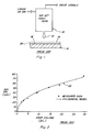
- an ink jet print head 10 is shown ejecting a liquid drop 12 onto a surface 14 of a treated plate 16 in an image wise manner for making or completing a printing plate.
- Plate 16 includes a substrate 18 of a conventional material such as aluminum or polyester, and a layer 20 of a known surface treatment to control spreading of ink and other liquids deposited on surface 14.
- Layer 20 can include, but is not limited to, surfactants with hydrophilic heads and hydrophobic tails, and other well known substances.
- Liquid drops are delivered to surface 14 in an image wise manner and comprise a liquid, such as a liquid containing a polymer such as, but not limited to, a pyridine-containing polymer, which has an observed ability after drying to pick up and deliver printing inks to a blanket roller of a printing press, and excellent durability even after much use.
- a liquid such as a liquid containing a polymer such as, but not limited to, a pyridine-containing polymer, which has an observed ability after drying to pick up and deliver printing inks to a blanket roller of a printing press, and excellent durability even after much use.
- layer 20 can include for instance any of the substances identified as the first material for picking up ink, or a primer, as disclosed in Fromson et al. U.S. Patent No. 5,750,314, discussed hereinabove and incorporated herein by reference, drops 12 being suitably composed of a compatible adhesive or other of the second materials disclosed in the Fromson et al. patent.
- print head 10 can be used to deliver ink drops to a surface of a proofing receiver (not shown) in a similar image wise manner to produce a proof of a work to be printed using plate 16, the delivered ink drops and liquid drops being of different predetermined volumes so as to form corresponding printed dots on the plate or proofing receiver such that the image of the proof is accurately representative of or replicates the image to be printed using the plate, the different drop volumes being controlled by drive signals received from drive circuitry for the print head or print heads.
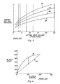
- a curve 22 is shown illustrating a known relationship of dot diameter in micrometers ( ⁇ m) to drop volume in picoliters ( p L) for typical printed dots, it being observed that dot size increases as drop volume increases.
- curves 24, 26, 28, and 32 illustrate the relationship of dot diameter to jetted drop volume for dots of various liquids delivered by a typical ink jet printer onto plates having layers of a variety of different treatments thereon, namely, curve 32 representing no treatment and curves 24, 26, 28 representing varying types of chemical treatments, respectively.
- a curve 34 represents measured percent area coverage as a function of nominal percent area coverage for typical dots on a conventional printing plate
- a curve 36 represents measured percent area coverage as a function of nominal percent area coverage for dots printed on a printing receiver such as press paper using the printing plate
- the vertical distance, represented as X, between curves 34 and 36 at any given point representing dot gain, that is, the difference between the percent of area covered by the dot formed on the printing plate, and the percent of area of the dot printed on the paper by the dot on the printing plate.
- the percent area coverage on the print is 15-18 percent larger than the percent area coverage on the plate, and the printed dot will be 7-10 percent larger than the dot on the plate.
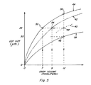
- curve 38 represents dot size as a function of drop volume for dots formed on a treated plate such as plate 16 in the manner described above with reference to Fig. 1.
- Curve 40 represents dot size as a function of drop volume for ink dots printed on paper by the dots of curve 38, the vertical distance between curves 38 and 40 corresponding to the dot gain.
- Curve 42 represents dot size as a function of drop volume for dots printed by an ink jet printer on a treated paper
- curve 44 represents dot size as a function of drop volume for dots printed by an ink jet printer on a conventional proofing paper.
- the required drop volume of the liquid used for producing the dots on the printing plate in the manner described in reference to Fig. 1 would be 12 pL.
- the resulting size of dots printed by the dots on the treated plate would then be 33 um, as shown at point 48 on curve 40, due to the dot gain. If the ink jet printer were used to print ink dots on the proofing paper of curve 44 using the same drop volume, the resultant dots would have a size substantially greater than 33 um, as shown at point 50.
- the resultant dots printed on the proofing paper would be the desired 33 um size, as shown at point 52, such that a proof printed with the 7 pL drops will be accurately representative of a print printed by the dots on the treated plate made using the 12 pL drops.
- a proof printed on treated paper using 9 pL drops would have the desired 33 um size dots, as shown at point 54 on curve 42.
- ink jet printheads can be made to produce drops of different volumes by varying parameters of the drive signals used for producing the drops. For instance, for some printers it has been found generally that drop volume can be varied as a function of signal frequency, a plot 56 of drop volume verses drive signal frequency, generally, being shown in Fig. 6a, illustrating a decrease in drop volume as drive signal frequency increases. Referring to Fig. 6b, a plot 58 of drop volume verses drive signal frequency for a typical shear-mode piezoelectric ink jet print head is shown, again, drop volume generally decreasing as the drive signal frequency increases.
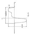
- a trace 58 of a drive signal wave form for a shear-mode piezoelectric ink jet print head is shown, the vertical axis representing voltage and the horizontal axis representing time, the wave form frequency and voltage amplitude of the trace being denoted.
- Fig. 7b shows trace 58 and a second drive signal wave form trace 60, trace 58 being representative of a drive signal having a frequency of about 120 kHz, and trace 60 being representative of a 60 kHz drive signal of the same amplitude, for driving a shear-mode piezoelectric ink jet printer for producing a 7 pL drop and a 12 pL drop, respectively.
- a 12 pL drop of a liquid for forming a printing plate will result in a 33 um printed dot on the press, and a 7 pL drop of ink will form a 33 um printed dot on a piece of proofing paper.
- traces 62 and 64 for a shear-mode piezoelectric ink jet printer are shown, both traces 62 and 64 having a generally sinusoidal wave form shape, trace 62 having a single drive pulse and trace 64 having a two drive pulses, for producing smaller and larger drops, respectively.
- Apparatus 66 includes a first element 68 including circuitry 70 controllably operable for generating ink drops of a first predetermined volume for printing the proof on a proofing receiver.
- Circuitry 70 includes a first clock 72 selectably connectable by a switch 74 in electrical communication with a signal generator 76 for driving signal generator 76 at a first frequency.
- Signal generator 76 is connected in electrical communication with a machine control 78 and an amplifier 80, which, in turn, is selectably connectable in electrical communication with a first ink jet print head 82 by a switch 84.
- Apparatus 66 includes a second element 86 including circuitry 88 controllably operable for generating liquid drops of a second predetermined volume for making the printing plate, the second predetermined volume being different from the first predetermined volume.
- Circuitry 88 includes a second clock 90 selectably connectable by switch 74 in electrical communication with signal generator 76 for driving signal generator 76 at a second frequency, signal generator 76 again being connected to machine control 78 and to amplifier 80, which, in turn, is selectably connectable to a second ink jet print head 92 by switch 84.
- Switches 74 and 84 can be jointly switchable, for instance by machine control 78, as desired, to allow selecting the first or second frequency and associated print head 82, 92.
- Print heads 82 and 92 are threadedly mounted for longitudinal movement on a rotatable cross screw 94 in spaced, opposed relation to a platen 96.
- Platen 96 in turn is threadedly mounted for longitudinal movement on a lead screw 98 oriented at a right angle to cross screw 94.
- Cross screw 94 is rotatable by a drive motor 100
- lead screw 98 is rotatable by a similar drive motor (not shown) while print heads 82, 92 are prevented from rotating, for relatively moving print heads 82, 92 and platen 96 longitudinally along the screws in the well known conventional manner for positioning the print heads 82, 92 in desired relation to a top surface 102 of the platen.
- Top surface 102 is conventionally adapted for receiving a printing plate such as treated plate 16 and/or a proofing receiver, such as a piece of paper, as represented by element 104, and holding the plate or receiver using vacuum or the like, for receiving ink or liquid drops in an image wise manner during the relative movement.
- Print head 82 is connected in fluid communication with an ink source 106 such as a tank or reservoir containing inks, which may include one to six or more different ink colors
- print head 92 is connected in fluid communication with a source of liquid 108 for making a printing plate such as plate 16, by flexible lines 110 and 112, respectively, to provide ink or liquid delivery to the print heads 82, 92 during the relative movement.
- Signal generator 76 is adaptable for generating drive signals having any of the wave form shapes shown in Figs. 7a, 7b and 7c, at a frequency determined by the clock 72 or 90 selectably connectable thereto.
- the frequency of first clock 72 can be set to produce the above discussed 120 kHz for driving print head 82 for producing ink drops having a volume of 7 pL
- the frequency for second clock 90 can be set to produce the above discussed 60 kHz for driving print head 92 for producing 12 pL liquid drops for making the printing plate.
- a resultant proof printed using ink drops of 7 pL volume will have image wise dots of a 33 um size, and prints printed by the printing plate made using 12 pL liquid drops will also have 33 um dots, such that the proof will accurately reproduce or replicate the image to be printed using the printing plate.
- a proof accurately representative of or replicating a work to be printed using a printing plate can be produced by an ink jet printer.
- this is achieved by utilizing a drive signal for the ink jet printer operable for emitting ink drops of a volume for producing printed dots on a selected proofing receiver of a size equal or substantially equal to the dot size of the work when printed using the printing plate.
- the required drop volume can be achieved by adjusting the frequency of the drive signal, the wave form thereof, the amplitude thereof, or any other characteristic which suitably effects drop volume.
- the ink jet printer can utilize a wide variety of conventional print head constructions, including, but not limited to, a shear-mode piezoelectric print head.
- the printer platen may be flat, or it may be in the form of a moving cylinder.
- the print head drive waveforms may be varied by changing the signal generator frequency, or by retrieving any one of a number of digital waveforms, stored in memory.
- the printer may also include a single print head for making the printing plate and printing the proof, or different print heads for those functions.
- the treated plate for instance, can be an aluminum or polyester plate having a surface treatment to control spreading of ink drops thereon.
- the liquid deposited on the treated surface for instance, can include but is not limited to a liquid containing a polymer such as pyridine-containing polymers.
- a printing plate and a proof of a work to be printed using the printing plate can be produced using the same apparatus.
- an accurate proof of a work to be printing using a printing plate can be produced, thus avoiding cost and time lost producing an undesirable or incorrect printing plate.
Abstract
Description
- The present invention relates to an ink jet printer apparatus and method, and more particularly, to an ink jet printer and method for making a printing plate and a proof of a work such as text and/or an image to be printed by the printing plate.
- When printing, a printing plate for a work is typically made, and then one or more proofs of the work are printed using the printing plate to allow determining desirability and accuracy of the printed image before a large number of prints are printed. The proofing activity might take several stages: an initial, creative stage in which a computer display might be adequate for proofing; an intermediate stage in which a desktop-type inkjet or thermal printer output might be used; and a final, more critical stage in which an accurate picture of the final plate result, including the micro-structure of the halftone dots to be produced on the plate, is desired. It is toward this last need for an accurate halftone proofer, matched to a corresponding platemaker, that the present invention is directed.
- It is known to use an ink jet printer to make printing plates. Reference in this regard, Fromson et al. U.S. Patent No. 5,750,314 issued May 12, 1998 which discloses a method for selectively imaging a lithographic printing plate using an ink jet printer. In the Fromson et al. method, a substrate is coated with a first material, which is soluble in a first solvent, whereupon a second material, which strongly adheres to the first material and insoluble in the first solvent, is selectively applied by an ink jet printer. The substrate is then developed in the first solvent to establish the image. However, Fromson et al. does not disclose a method or apparatus for producing a proof of a work to be printed, without first requiring making the printing plate.
- Therefore, an object of the present invention is to provide an ink jet printer and method for printing an accurate proof of a work to be printed using a printing plate without first requiring making the printing plate, and for making the printing plate.
- With the above object in view, the present invention is defined by the several claims appended hereto.
- According to an exemplary embodiment of the present invention, the ink jet printer includes a first print head connected in fluid communication with a source of ink for printing the proof of the work, and a second print head in fluid communication with a source of a liquid for making the printing plate, the print heads being disposed for ejecting drops of the ink and the liquid image wise onto a proofing receiver and a treated plate, respectively, positionable on a platen relatively moveable with respect to the print heads. The first element is connected in electrical communication with the first print head and includes a first clock connected to a signal generator operable for producing a drive signal for driving the print head for generating the ink drops of the first predetermined volume for printing the proof on the proofing receiver. The second element includes a second clock connected to the signal generator and operable in conjunction therewith for driving the second print head for generating the liquid drops for printing the image on the treated plate for making or completing the printing plate. A machine control is connected to the signal generator and is operable for selecting the first print head and the first clock for ej ecting the ink drops image wise onto the proofing receiver, which can be a sheet of proofing paper or the like, for creating the proof, or the second print head and the second clock for ejecting the liquid image wise onto the treated plate for making or completing the printing plate.
- The treated plate for instance can be a grained, anodized aluminum or polyester plate having a hydrophilic surface and having a known surface treatment to control spreading of ink drops thereon. The liquid deposited on the treated surface for instance can include an oleophilic liquid containing a polymer such as pyridine-containing polymer. Such liquids are preferred as they have a known ability to pick up and deliver printing inks to a blanket roller of a printing press. Such liquids are also known for the durability of the dried spots that are formed.
- A feature of the present invention is the provision of an ink jet printer adapted for making or image wise completing a printing plate, and a proof of a work to be printed using the printing plate without first requiring making the printing plate.
- Another feature of the invention is the provision of an ink jet printer operable to produce drops having different characteristics for printing corresponding images of a work on different printing receivers.
- As an advantage of the present invention, a printing plate and a proof of a work to be printed using the printing plate can be produced using the same apparatus.
- As another advantage, an accurate proof of a work to be printed using a printing plate can be produced, thus avoiding cost and time lost producing an undesirable or incorrect printing plate.
- According to the invention, the volume characteristics of drops of ink or other liquid produced by an ink jet printer can be varied by altering aspects of the drive signal used for producing the drops, including, but not limited to, the voltage, frequency, and/or wave form of the drive signal.
- These and other objects, features an advantages of the present invention will become apparent to those skilled in the art upon a reading of the following detailed description when taken in conjunction with the drawings wherein there are shown and described illustrative embodiments of the invention.
- While the specification concludes with the claims particularly pointing out and distinctly claiming the subject matter of the present invention, it is believed the invention will be better understood from the following detailed description when taken in conjunction with the accompanying drawings wherein:
- Figure 1 is a simplified schematic view of an ink jet print head showing ejection of a liquid drop therefrom onto a treated plate;
- Figure 2 is a graphical representation of dot diameter versus drop volume for printing receivers generally;
- Figure 3 is another graphical representation of dot diameter versus drop volume for a variety of different receiving surfaces;
- Figure 4 is a graphical representation of percent measured dot area versus nominal percent dot area for a conventional printing plate, illustrating dot gain;
- Figure 5 is a graphical representation of dot size versus drop volume for several printing receivers and a selected treated plate;
- Figure 6a is a graphical representation of a drop volume versus drive signal frequency, generally;
- Figure 6b is another graphical representation of drop volume versus drive signal frequency for a representative piezoelectric ink jet print head;
- Figure 7a is a graphical representation of a drive signal wave form according to the present invention;
- Figure 7b is a graphical representation of the drive signal wave form of Fig. 7a and a second drive signal wave form according to the invention;
- Figure 7c is a graphical representation of other drive signal wave forms according to the invention; and
- Figure 8 is a schematic representation of an ink jet printer according to the invention.
-
- The present description will be directed in particular to elements forming part of, or cooperating more directly with, an apparatus and method in accordance with the present invention. It is to be understood that elements not specifically shown or described may take various forms well known to those skilled in the art.
- Therefore, referring to Fig. 1, an ink
jet print head 10 is shown ejecting aliquid drop 12 onto asurface 14 of a treatedplate 16 in an image wise manner for making or completing a printing plate.Plate 16 includes asubstrate 18 of a conventional material such as aluminum or polyester, and alayer 20 of a known surface treatment to control spreading of ink and other liquids deposited onsurface 14.Layer 20 can include, but is not limited to, surfactants with hydrophilic heads and hydrophobic tails, and other well known substances. Liquid drops, represented bydrop 12, are delivered tosurface 14 in an image wise manner and comprise a liquid, such as a liquid containing a polymer such as, but not limited to, a pyridine-containing polymer, which has an observed ability after drying to pick up and deliver printing inks to a blanket roller of a printing press, and excellent durability even after much use. - As another alternative,
layer 20 can include for instance any of the substances identified as the first material for picking up ink, or a primer, as disclosed in Fromson et al. U.S. Patent No. 5,750,314, discussed hereinabove and incorporated herein by reference,drops 12 being suitably composed of a compatible adhesive or other of the second materials disclosed in the Fromson et al. patent. - According to the present invention,
print head 10, or another print head, can be used to deliver ink drops to a surface of a proofing receiver (not shown) in a similar image wise manner to produce a proof of a work to be printed usingplate 16, the delivered ink drops and liquid drops being of different predetermined volumes so as to form corresponding printed dots on the plate or proofing receiver such that the image of the proof is accurately representative of or replicates the image to be printed using the plate, the different drop volumes being controlled by drive signals received from drive circuitry for the print head or print heads. - Referring to Fig. 2, a
curve 22 is shown illustrating a known relationship of dot diameter in micrometers (µm) to drop volume in picoliters (pL) for typical printed dots, it being observed that dot size increases as drop volume increases. - Referring to Fig. 3,
curves curve 32 representing no treatment andcurves - In Fig. 4, a curve 34 represents measured percent area coverage as a function of nominal percent area coverage for typical dots on a conventional printing plate, and a curve 36 represents measured percent area coverage as a function of nominal percent area coverage for dots printed on a printing receiver such as press paper using the printing plate, the vertical distance, represented as X, between curves 34 and 36 at any given point representing dot gain, that is, the difference between the percent of area covered by the dot formed on the printing plate, and the percent of area of the dot printed on the paper by the dot on the printing plate. Typically, it has been found that the percent area coverage on the print is 15-18 percent larger than the percent area coverage on the plate, and the printed dot will be 7-10 percent larger than the dot on the plate.
- To illustrate the effect of this difference in dot sizes, reference is made to Fig. 5 wherein
curve 38 represents dot size as a function of drop volume for dots formed on a treated plate such asplate 16 in the manner described above with reference to Fig. 1.Curve 40 represents dot size as a function of drop volume for ink dots printed on paper by the dots ofcurve 38, the vertical distance betweencurves curve 44 represents dot size as a function of drop volume for dots printed by an ink jet printer on a conventional proofing paper. - As an example, if it were decided to make a printing plate having a dot size of 30 um, as shown at
point 46, usingcurve 38, the required drop volume of the liquid used for producing the dots on the printing plate in the manner described in reference to Fig. 1 would be 12 pL. The resulting size of dots printed by the dots on the treated plate would then be 33 um, as shown atpoint 48 oncurve 40, due to the dot gain. If the ink jet printer were used to print ink dots on the proofing paper ofcurve 44 using the same drop volume, the resultant dots would have a size substantially greater than 33 um, as shown atpoint 50. However, if the drop volume were reduced to 7 pL, the resultant dots printed on the proofing paper would be the desired 33 um size, as shown atpoint 52, such that a proof printed with the 7 pL drops will be accurately representative of a print printed by the dots on the treated plate made using the 12 pL drops. Similarly, a proof printed on treated paper using 9 pL drops would have the desired 33 um size dots, as shown atpoint 54 on curve 42. This demonstrates that characteristics or parameters of the paper used for proofing can be varied to facilitate matching dot size with a print made using a printing plate, for instance by minimizing the difference between the liquid drop volume required for making the printing plate and the ink drop volume required for making the matching proof. - It has been found that some ink jet printheads can be made to produce drops of different volumes by varying parameters of the drive signals used for producing the drops. For instance, for some printers it has been found generally that drop volume can be varied as a function of signal frequency, a
plot 56 of drop volume verses drive signal frequency, generally, being shown in Fig. 6a, illustrating a decrease in drop volume as drive signal frequency increases. Referring to Fig. 6b, aplot 58 of drop volume verses drive signal frequency for a typical shear-mode piezoelectric ink jet print head is shown, again, drop volume generally decreasing as the drive signal frequency increases. - Turning to Fig. 7a, a
trace 58 of a drive signal wave form for a shear-mode piezoelectric ink jet print head is shown, the vertical axis representing voltage and the horizontal axis representing time, the wave form frequency and voltage amplitude of the trace being denoted. Fig. 7b showstrace 58 and a second drive signalwave form trace 60,trace 58 being representative of a drive signal having a frequency of about 120 kHz, and trace 60 being representative of a 60 kHz drive signal of the same amplitude, for driving a shear-mode piezoelectric ink jet printer for producing a 7 pL drop and a 12 pL drop, respectively. Referring back to the discussion with reference to Fig. 5, a 12 pL drop of a liquid for forming a printing plate will result in a 33 um printed dot on the press, and a 7 pL drop of ink will form a 33 um printed dot on a piece of proofing paper. - Referring to Fig. 7c, alternative drive signal traces 62 and 64 for a shear-mode piezoelectric ink jet printer are shown, both traces 62 and 64 having a generally sinusoidal wave form shape, trace 62 having a single drive pulse and trace 64 having a two drive pulses, for producing smaller and larger drops, respectively.
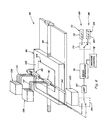
- Referring to Fig. 8, an ink jet proof making and printing plate making apparatus constructed and operable according to the above-discussed teachings of the present invention is shown.
Apparatus 66 includes afirst element 68 includingcircuitry 70 controllably operable for generating ink drops of a first predetermined volume for printing the proof on a proofing receiver.Circuitry 70 includes afirst clock 72 selectably connectable by aswitch 74 in electrical communication with asignal generator 76 for drivingsignal generator 76 at a first frequency.Signal generator 76 is connected in electrical communication with amachine control 78 and anamplifier 80, which, in turn, is selectably connectable in electrical communication with a first inkjet print head 82 by aswitch 84.Apparatus 66 includes asecond element 86 includingcircuitry 88 controllably operable for generating liquid drops of a second predetermined volume for making the printing plate, the second predetermined volume being different from the first predetermined volume.Circuitry 88 includes asecond clock 90 selectably connectable byswitch 74 in electrical communication withsignal generator 76 for drivingsignal generator 76 at a second frequency,signal generator 76 again being connected tomachine control 78 and toamplifier 80, which, in turn, is selectably connectable to a second inkjet print head 92 byswitch 84.Switches machine control 78, as desired, to allow selecting the first or second frequency and associatedprint head - Print heads 82 and 92 are threadedly mounted for longitudinal movement on a
rotatable cross screw 94 in spaced, opposed relation to aplaten 96.Platen 96, in turn is threadedly mounted for longitudinal movement on alead screw 98 oriented at a right angle to crossscrew 94.Cross screw 94 is rotatable by adrive motor 100, and leadscrew 98 is rotatable by a similar drive motor (not shown) while print heads 82, 92 are prevented from rotating, for relatively moving print heads 82, 92 andplaten 96 longitudinally along the screws in the well known conventional manner for positioning the print heads 82, 92 in desired relation to atop surface 102 of the platen.Top surface 102 is conventionally adapted for receiving a printing plate such as treatedplate 16 and/or a proofing receiver, such as a piece of paper, as represented byelement 104, and holding the plate or receiver using vacuum or the like, for receiving ink or liquid drops in an image wise manner during the relative movement.Print head 82 is connected in fluid communication with anink source 106 such as a tank or reservoir containing inks, which may include one to six or more different ink colors, andprint head 92 is connected in fluid communication with a source ofliquid 108 for making a printing plate such asplate 16, byflexible lines -
Signal generator 76 is adaptable for generating drive signals having any of the wave form shapes shown in Figs. 7a, 7b and 7c, at a frequency determined by theclock first clock 72 can be set to produce the above discussed 120 kHz for drivingprint head 82 for producing ink drops having a volume of 7 pL, and the frequency forsecond clock 90 can be set to produce the above discussed 60 kHz for drivingprint head 92 for producing 12 pL liquid drops for making the printing plate. Again referring to Fig. 5, a resultant proof printed using ink drops of 7 pL volume will have image wise dots of a 33 um size, and prints printed by the printing plate made using 12 pL liquid drops will also have 33 um dots, such that the proof will accurately reproduce or replicate the image to be printed using the printing plate. - It may be appreciated from the description hereinabove, that according to the present invention, a proof accurately representative of or replicating a work to be printed using a printing plate can be produced by an ink jet printer. As taught above, this is achieved by utilizing a drive signal for the ink jet printer operable for emitting ink drops of a volume for producing printed dots on a selected proofing receiver of a size equal or substantially equal to the dot size of the work when printed using the printing plate. The required drop volume can be achieved by adjusting the frequency of the drive signal, the wave form thereof, the amplitude thereof, or any other characteristic which suitably effects drop volume.
- It may also be appreciated that the ink jet printer can utilize a wide variety of conventional print head constructions, including, but not limited to, a shear-mode piezoelectric print head. The printer platen may be flat, or it may be in the form of a moving cylinder. The print head drive waveforms may be varied by changing the signal generator frequency, or by retrieving any one of a number of digital waveforms, stored in memory. The printer may also include a single print head for making the printing plate and printing the proof, or different print heads for those functions. The treated plate, for instance, can be an aluminum or polyester plate having a surface treatment to control spreading of ink drops thereon. The liquid deposited on the treated surface, for instance, can include but is not limited to a liquid containing a polymer such as pyridine-containing polymers.
- It may be further appreciated that as an advantage of the present invention, a printing plate and a proof of a work to be printed using the printing plate can be produced using the same apparatus.
- As another advantage, an accurate proof of a work to be printing using a printing plate can be produced, thus avoiding cost and time lost producing an undesirable or incorrect printing plate.
- Therefore, what is provided is an ink jet printer and method for printing an accurate proof of a work to be printed using a printing plate without first requiring making the printing plate, and for making the printing plate.
-
- 10
- ink jet print head
- 12
- fluid droplet
- 14
- surface
- 16
- treated plate
- 18
- substrate
- 20
- layer
- 22
- graph
- 24
- curve
- 26
- curve
- 28
- curve
- 32
- curve
- 34
- curve
- 36
- curve
- 38
- curve
- 40
- curve
- 42
- curve
- 44
- curve
- 46
- point
- 48
- point
- 50
- point
- 52
- point
- 54
- point
- 56
- representative plot
- 58
- representative plot
- 60
- trace
- 62
- trace
- 64
- trace
- 66
- apparatus
- 68
- first element
- 70
- circuitry
- 72
- first clock
- 74
- switch
- 76
- signal generator
- 78
- machine control
- 80
- amplifier
- 82
- first ink jet print head
- 84
- switch
- 86
- second element
- 88
- circuitry
- 90
- second clock
- 92
- second ink jet print head
- 94
- cross screw
- 96
- platen
- 98
- lead screw
- 100
- drive motor
- 102
- top surface
- 104
- representative element
- 106
- ink source
- 108
- source of liquid
- 110
- line
- 112
- line
Claims (10)
- An ink jet printer for printing a proof of a work to be printed and making a printing plate for printing the work, comprising;a first element (68) including circuitry (70) controllably operable for generating ink drops (12) of a first predetermined volume for printing the proof on a proofing receiver; anda second element (86) including circuitry (88) controllably operable for generating liquid drops of a second predetermined volume for making the printing plate, the second predetermined volume being different from the first predetermined volume.
- The ink jet printer of Claim 1, wherein the first and second elements each comprise a piezoelectric print head (82, 92).
- The ink jet printer of Claim 2, further comprising a platen (96) adapted for holding the printing plate and the proofing receiver and apparatus for relatively moving the platen and the piezoelectric print heads.
- The ink jet printer of Claim 2, wherein the circuitry of the first element includes a first clock (72) operable at a first speed, the circuitry of the second element includes a second clock (90) operable at a second speed different from the first speed, and the printer includes a signal generator connectable in driven relation to the first and second clocks, respectively, and in driving relation to the print heads, respectively.
- The ink jet printer of Claim 1, wherein the circuitry includes a signal generator (76) operable for controlling the volume of the generated drops by controlling a voltage parameter of a drive signal generated thereby.
- The ink jet printer of Claim 1, wherein the circuitry includes a signal generator operable for controlling the volume of the generated drops by controlling a wave form parameter of a drive signal generated thereby.
- A method for printing a proof of a work to be printed and making a printing plate for the work, comprising the steps of:a. providing an ink jet printer including circuitry and a print head controllably operable for generating ink drops of a first predetermined volume for printing the proof of the work on a proofing receiver, and circuitry and a print head controllably operable for generating drops of a second predetermined volume of a liquid for making the printing plate, the second predetermined volume being different from the first predetermined volume;b. controllably operating the first named circuitry and print head for printing the proof on a printing receiver; andc. controllably operating the second named circuitry and print head for making the printing plate.
- The method of Claim 7, wherein the first named circuitry and print head is controllably operated at a first drive signal frequency.
- The method of Claim 8, wherein the second named circuitry and print head is controllably operated at a second drive signal frequency that is different in frequency from the first drive signal frequency.
- The method of Claim 7, wherein the first named circuitry and print head is operated for generating said ink drops of the first predetermined volume using a first drive signal wave form and the second named circuitry and print head is operated for generating said ink drops of said second predetermined volume using a second drive signal wave form different from said first drive signal wave form.
Applications Claiming Priority (2)
| Application Number | Priority Date | Filing Date | Title |
|---|---|---|---|
| US516707 | 2000-03-01 | ||
| US09/516,707 US6352330B1 (en) | 2000-03-01 | 2000-03-01 | Ink jet plate maker and proofer apparatus and method |
Publications (2)
| Publication Number | Publication Date |
|---|---|
| EP1129846A1 true EP1129846A1 (en) | 2001-09-05 |
| EP1129846B1 EP1129846B1 (en) | 2005-05-25 |
Family
ID=24056763
Family Applications (1)
| Application Number | Title | Priority Date | Filing Date |
|---|---|---|---|
| EP01200574A Expired - Lifetime EP1129846B1 (en) | 2000-03-01 | 2001-02-19 | Ink jet plate maker and proofer apparatus and method |
Country Status (5)
| Country | Link |
|---|---|
| US (1) | US6352330B1 (en) |
| EP (1) | EP1129846B1 (en) |
| JP (1) | JP2001260308A (en) |
| DE (1) | DE60110953T2 (en) |
| IL (1) | IL140879A (en) |
Cited By (1)
| Publication number | Priority date | Publication date | Assignee | Title |
|---|---|---|---|---|
| WO2005105463A1 (en) * | 2004-05-05 | 2005-11-10 | Glunz & Jensen A/S | System and method for inkjet printing |
Families Citing this family (17)
| Publication number | Priority date | Publication date | Assignee | Title |
|---|---|---|---|---|
| US20010043240A1 (en) * | 2000-04-14 | 2001-11-22 | Asahi Glass Company | Method for preparing proof for plate printing, and recording medium |
| ATE435749T1 (en) | 2002-04-09 | 2009-07-15 | Seiko Epson Corp | FLUID INJECTION HEAD |
| US6864216B2 (en) | 2002-05-22 | 2005-03-08 | Eastman Kodak Company | Thermal magenta donor and dyes |
| US6869909B2 (en) | 2002-05-22 | 2005-03-22 | Eastman Kodak Company | Yellow images with improved light stability and yellow dyes useful therein |
| US7241719B2 (en) | 2002-05-22 | 2007-07-10 | Eastman Kodak Company | Thermal yellow donor and dyes |
| US6841514B2 (en) | 2002-12-26 | 2005-01-11 | Eastman Kodak Company | Thermal transfer imaging element containing infrared bichromophoric colorant |
| JP2004243548A (en) * | 2003-02-12 | 2004-09-02 | Konica Minolta Holdings Inc | Image forming method, ink jet recording apparatus and active ray curable ink used therein |
| US7004571B2 (en) * | 2003-02-25 | 2006-02-28 | Eastman Kodak Company | Preventing defective nozzle ink discharge in continuous inkjet printhead from being used for printing |
| US6899030B2 (en) * | 2003-05-05 | 2005-05-31 | Eastman Kodak Company | Lithographic plate imaging system to minimize plate misregistration for multicolor printing applications |
| US8491076B2 (en) * | 2004-03-15 | 2013-07-23 | Fujifilm Dimatix, Inc. | Fluid droplet ejection devices and methods |
| US7281778B2 (en) | 2004-03-15 | 2007-10-16 | Fujifilm Dimatix, Inc. | High frequency droplet ejection device and method |
| JP5004806B2 (en) | 2004-12-30 | 2012-08-22 | フジフィルム ディマティックス, インコーポレイテッド | Inkjet printing method |
| KR100765758B1 (en) * | 2005-09-12 | 2007-10-15 | 삼성전자주식회사 | Ink cartridge assembly and inkjet image forming apparatus with the same |
| US7988247B2 (en) | 2007-01-11 | 2011-08-02 | Fujifilm Dimatix, Inc. | Ejection of drops having variable drop size from an ink jet printer |
| US8393702B2 (en) * | 2009-12-10 | 2013-03-12 | Fujifilm Corporation | Separation of drive pulses for fluid ejector |
| US9096056B2 (en) * | 2011-05-19 | 2015-08-04 | Xerox Corporation | Apparatus and method for measuring drop volume |
| WO2016175812A1 (en) | 2015-04-30 | 2016-11-03 | Hewlett-Packard Development Company, L.P. | Dual and single drop weight printing |
Citations (11)
| Publication number | Priority date | Publication date | Assignee | Title |
|---|---|---|---|---|
| US3280974A (en) | 1961-08-23 | 1966-10-25 | John B Riddle | Method and apparatus for recognizing printed currency |
| US3870629A (en) | 1973-10-11 | 1975-03-11 | Umc Ind | Paper currency validator |
| US4593184A (en) | 1983-08-19 | 1986-06-03 | Brandt, Incorporated | Counterfeit detection circuit |
| US4617458A (en) | 1985-02-11 | 1986-10-14 | Brandt, Inc. | Counterfeit detection circuit |
| US4992860A (en) | 1988-03-29 | 1991-02-12 | Mitsubishi Denki Kabushiki Kaisha | Color scanning system |
| US5151607A (en) | 1991-05-02 | 1992-09-29 | Crane Timothy T | Currency verification device including ferrous oxide detection |
| US5295196A (en) | 1990-02-05 | 1994-03-15 | Cummins-Allison Corp. | Method and apparatus for currency discrimination and counting |
| EP0776763A1 (en) * | 1995-11-30 | 1997-06-04 | Sun Chemical Corporation | Process for the production of lithographic printing plates |
| US5750314A (en) | 1995-12-05 | 1998-05-12 | Howard A. Fromson | Method for selectively imaging a lithographic printing plate |
| US6019045A (en) * | 1997-04-25 | 2000-02-01 | Fuji Photo Film Co., Ltd. | Process for the preparation of ink jet process printing plate |
| US6164757A (en) * | 1997-10-30 | 2000-12-26 | Eastman Kodak Company | Apparatus for printing proof image and producing lithographic plate |
Family Cites Families (31)
| Publication number | Priority date | Publication date | Assignee | Title |
|---|---|---|---|---|
| US4439789A (en) | 1980-04-11 | 1984-03-27 | Coulter Systems Corporation | Binary scan system |
| DE3128801A1 (en) | 1980-07-22 | 1982-04-15 | Canon K.K., Tokyo | "IMAGE GENERATION DEVICE" |
| US4409596A (en) * | 1980-08-12 | 1983-10-11 | Epson Corporation | Method and apparatus for driving an ink jet printer head |
| JPS58138656A (en) | 1982-02-12 | 1983-08-17 | Canon Inc | Recorder |
| JPS58140886A (en) | 1982-02-17 | 1983-08-20 | Canon Inc | Computer with printer |
| US4708459A (en) * | 1986-03-11 | 1987-11-24 | Eastman Kodak Company | Electrophotographic color proofing apparatus and method |
| US5278578A (en) | 1989-12-18 | 1994-01-11 | Eastman Kodak Company | Thermal printer capable of using dummy lines to prevent banding |
| US5053791A (en) | 1990-04-16 | 1991-10-01 | Eastman Kodak Company | Thermal transfer print medium drum system |
| US5103244A (en) * | 1990-07-05 | 1992-04-07 | Hewlett-Packard Company | Method and apparatus for cleaning ink-jet printheads |
| US5109460A (en) | 1991-08-23 | 1992-04-28 | Eastman Kodak Company | Optical fiber array for a thermal printer and method of making same |
| US5268708A (en) | 1991-08-23 | 1993-12-07 | Eastman Kodak Company | Laser thermal printer with an automatic material supply |
| US5323179A (en) | 1991-08-23 | 1994-06-21 | Eastman Kodak Company | Method of calibrating a multichannel printer |
| US5258777A (en) | 1991-08-23 | 1993-11-02 | Eastman Kodak Company | Thermal printer system with a high aperture micro relay lens system |
| US5754218A (en) | 1992-06-03 | 1998-05-19 | Eastman Kodak Company | Variable dot density printing system using sub-microdot matrixing and a zoom lens |
| US5371531A (en) * | 1992-11-12 | 1994-12-06 | Xerox Corporation | Thermal ink-jet printing with fast- and slow-drying inks |
| CN1077048C (en) | 1993-04-20 | 2002-01-02 | 旭化成株式会社 | Lithographic printing original plate and method for producing the same |
| JPH0740549A (en) * | 1993-07-26 | 1995-02-10 | Canon Inc | Ink jet recording and device |
| JP3311885B2 (en) | 1994-12-28 | 2002-08-05 | 富士写真フイルム株式会社 | Original plate for direct drawing type lithographic printing |
| US5836249A (en) | 1995-10-20 | 1998-11-17 | Eastman Kodak Company | Laser ablation imaging of zirconia-alumina composite ceramic printing member |
| US5839369A (en) | 1995-10-20 | 1998-11-24 | Eastman Kodak Company | Method of controlled laser imaging of zirconia alloy ceramic lithographic member to provide localized melting in exposed areas |
| US5855173A (en) | 1995-10-20 | 1999-01-05 | Eastman Kodak Company | Zirconia alloy cylinders and sleeves for imaging and lithographic printing methods |
| US5839370A (en) | 1995-10-20 | 1998-11-24 | Eastman Kodak Company | Flexible zirconia alloy ceramic lithographic printing tape and method of using same |
| JPH09197693A (en) | 1996-01-23 | 1997-07-31 | Fuji Photo Film Co Ltd | Original edition for direct drawing type planographic printing |
| US5836248A (en) | 1997-05-01 | 1998-11-17 | Eastman Kodak Company | Zirconia-alumina composite ceramic lithographic printing member |
| US5893328A (en) | 1997-05-01 | 1999-04-13 | Eastman Kodak Company | Method of controlled laser imaging of zirconia-alumina composite ceramic lithographic printing member to provide localized melting in exposed areas |
| JP3905177B2 (en) * | 1997-05-15 | 2007-04-18 | 富士フイルム株式会社 | Color conversion adjustment method |
| US5817482A (en) | 1997-06-20 | 1998-10-06 | Incyte Pharmaceuticals, Inc. | Disease related nucleotide kinases |
| US5919600A (en) | 1997-09-03 | 1999-07-06 | Kodak Polychrome Graphics, Llc | Thermal waterless lithographic printing plate |
| US5925496A (en) | 1998-01-07 | 1999-07-20 | Eastman Kodak Company | Anodized zirconium metal lithographic printing member and methods of use |
| US5927207A (en) | 1998-04-07 | 1999-07-27 | Eastman Kodak Company | Zirconia ceramic imaging member with hydrophilic surface layer and methods of use |
| US6140391A (en) * | 1998-10-09 | 2000-10-31 | Marconi Data Systems Inc. | Reactive jet ink composition |
-
2000
- 2000-03-01 US US09/516,707 patent/US6352330B1/en not_active Expired - Lifetime
-
2001
- 2001-01-12 IL IL14087901A patent/IL140879A/en not_active IP Right Cessation
- 2001-02-19 EP EP01200574A patent/EP1129846B1/en not_active Expired - Lifetime
- 2001-02-19 DE DE60110953T patent/DE60110953T2/en not_active Expired - Fee Related
- 2001-02-27 JP JP2001052894A patent/JP2001260308A/en not_active Withdrawn
Patent Citations (11)
| Publication number | Priority date | Publication date | Assignee | Title |
|---|---|---|---|---|
| US3280974A (en) | 1961-08-23 | 1966-10-25 | John B Riddle | Method and apparatus for recognizing printed currency |
| US3870629A (en) | 1973-10-11 | 1975-03-11 | Umc Ind | Paper currency validator |
| US4593184A (en) | 1983-08-19 | 1986-06-03 | Brandt, Incorporated | Counterfeit detection circuit |
| US4617458A (en) | 1985-02-11 | 1986-10-14 | Brandt, Inc. | Counterfeit detection circuit |
| US4992860A (en) | 1988-03-29 | 1991-02-12 | Mitsubishi Denki Kabushiki Kaisha | Color scanning system |
| US5295196A (en) | 1990-02-05 | 1994-03-15 | Cummins-Allison Corp. | Method and apparatus for currency discrimination and counting |
| US5151607A (en) | 1991-05-02 | 1992-09-29 | Crane Timothy T | Currency verification device including ferrous oxide detection |
| EP0776763A1 (en) * | 1995-11-30 | 1997-06-04 | Sun Chemical Corporation | Process for the production of lithographic printing plates |
| US5750314A (en) | 1995-12-05 | 1998-05-12 | Howard A. Fromson | Method for selectively imaging a lithographic printing plate |
| US6019045A (en) * | 1997-04-25 | 2000-02-01 | Fuji Photo Film Co., Ltd. | Process for the preparation of ink jet process printing plate |
| US6164757A (en) * | 1997-10-30 | 2000-12-26 | Eastman Kodak Company | Apparatus for printing proof image and producing lithographic plate |
Cited By (1)
| Publication number | Priority date | Publication date | Assignee | Title |
|---|---|---|---|---|
| WO2005105463A1 (en) * | 2004-05-05 | 2005-11-10 | Glunz & Jensen A/S | System and method for inkjet printing |
Also Published As
| Publication number | Publication date |
|---|---|
| JP2001260308A (en) | 2001-09-25 |
| DE60110953D1 (en) | 2005-06-30 |
| IL140879A (en) | 2004-06-20 |
| EP1129846B1 (en) | 2005-05-25 |
| IL140879A0 (en) | 2002-02-10 |
| US6352330B1 (en) | 2002-03-05 |
| DE60110953T2 (en) | 2006-05-18 |
Similar Documents
| Publication | Publication Date | Title |
|---|---|---|
| EP1129846B1 (en) | Ink jet plate maker and proofer apparatus and method | |
| JP3483618B2 (en) | Ink jet print head for dot printer | |
| US8016383B2 (en) | Liquid ejection head and image-forming apparatus using the same | |
| US6428135B1 (en) | Electrical waveform for satellite suppression | |
| US6102513A (en) | Ink jet printing apparatus and method using timing control of electronic waveforms for variable gray scale printing without artifacts | |
| EP1284184B1 (en) | Image forming method and apparatus | |
| CA2164891A1 (en) | Optimizing Printing Speed and Managing Printed Sheet Ejection Based on Image Density and Method of Determining Density | |
| US6705702B2 (en) | Inkjet printing using pigmented and dye-based inks | |
| JP3674998B2 (en) | Printer device | |
| US6561607B1 (en) | Apparatus and method for maintaining a substantially constant closely spaced working distance between an inkjet printhead and a printing receiver | |
| US20020023566A1 (en) | Computer-to-cylinder type lithographic printing method and computer-to-cylinder type lithographic printing apparatus | |
| EP1400359A3 (en) | Coalescence-free inkjet printing by controlling drop spreading on/in a receiver | |
| US6079806A (en) | Apparatus for producing halftone images suitable for lithographic printing plate | |
| EP0850776A3 (en) | Method of ink-jet printing using a phase-change ink | |
| US6074046A (en) | Printer apparatus capable of varying direction of an ink droplet to be ejected therefrom and method therefor | |
| US6450602B1 (en) | Electrical drive waveform for close drop formation | |
| DE60038491T2 (en) | LITHOGRAPHIC METHOD AND LITHOGRAPHIC DEVICE, METHOD AND DEVICE FOR PRODUCING A PRESSURE PLATE AND METHOD AND DEVICE FOR INK RAY PRINTING | |
| JPH06270380A (en) | Waterless lithographic plate making method | |
| JP2001129980A5 (en) | Inkjet recording equipment, image forming equipment, and printer driver | |
| US20010050016A1 (en) | Method and apparatus for making a printing plate | |
| JP3174545B2 (en) | Printing method and printing apparatus | |
| JPH08300693A (en) | Head driving control apparatus | |
| JP2000111660A (en) | Dial for timepiece and its manufacture | |
| JP3601150B2 (en) | Printer device and driving method thereof | |
| Zhou et al. | Applications of Page Wide Piezo Inkjet Printing to Commercial and Industrial Market |
Legal Events
| Date | Code | Title | Description |
|---|---|---|---|
| PUAI | Public reference made under article 153(3) epc to a published international application that has entered the european phase |
Free format text: ORIGINAL CODE: 0009012 |
|
| AK | Designated contracting states |
Kind code of ref document: A1 Designated state(s): AT BE CH CY DE DK ES FI FR GB GR IE IT LI LU MC NL PT SE TR |
|
| AX | Request for extension of the european patent |
Free format text: AL;LT;LV;MK;RO;SI |
|
| 17P | Request for examination filed |
Effective date: 20020202 |
|
| AKX | Designation fees paid |
Free format text: DE FR GB |
|
| GRAP | Despatch of communication of intention to grant a patent |
Free format text: ORIGINAL CODE: EPIDOSNIGR1 |
|
| GRAS | Grant fee paid |
Free format text: ORIGINAL CODE: EPIDOSNIGR3 |
|
| GRAA | (expected) grant |
Free format text: ORIGINAL CODE: 0009210 |
|
| AK | Designated contracting states |
Kind code of ref document: B1 Designated state(s): DE FR GB |
|
| REG | Reference to a national code |
Ref country code: GB Ref legal event code: FG4D |
|
| REF | Corresponds to: |
Ref document number: 60110953 Country of ref document: DE Date of ref document: 20050630 Kind code of ref document: P |
|
| PGFP | Annual fee paid to national office [announced via postgrant information from national office to epo] |
Ref country code: FR Payment date: 20060202 Year of fee payment: 6 |
|
| PGFP | Annual fee paid to national office [announced via postgrant information from national office to epo] |
Ref country code: DE Payment date: 20060228 Year of fee payment: 6 |
|
| ET | Fr: translation filed | ||
| PLBE | No opposition filed within time limit |
Free format text: ORIGINAL CODE: 0009261 |
|
| STAA | Information on the status of an ep patent application or granted ep patent |
Free format text: STATUS: NO OPPOSITION FILED WITHIN TIME LIMIT |
|
| 26N | No opposition filed |
Effective date: 20060228 |
|
| REG | Reference to a national code |
Ref country code: FR Ref legal event code: ST Effective date: 20071030 |
|
| PG25 | Lapsed in a contracting state [announced via postgrant information from national office to epo] |
Ref country code: DE Free format text: LAPSE BECAUSE OF NON-PAYMENT OF DUE FEES Effective date: 20070901 |
|
| PG25 | Lapsed in a contracting state [announced via postgrant information from national office to epo] |
Ref country code: FR Free format text: LAPSE BECAUSE OF NON-PAYMENT OF DUE FEES Effective date: 20070228 |
|
| PGFP | Annual fee paid to national office [announced via postgrant information from national office to epo] |
Ref country code: GB Payment date: 20120127 Year of fee payment: 12 |
|
| GBPC | Gb: european patent ceased through non-payment of renewal fee |
Effective date: 20130219 |
|
| PG25 | Lapsed in a contracting state [announced via postgrant information from national office to epo] |
Ref country code: GB Free format text: LAPSE BECAUSE OF NON-PAYMENT OF DUE FEES Effective date: 20130219 |