EP1129842A2 - Contact lens production line pallet system - Google Patents
Contact lens production line pallet system Download PDFInfo
- Publication number
- EP1129842A2 EP1129842A2 EP01201880A EP01201880A EP1129842A2 EP 1129842 A2 EP1129842 A2 EP 1129842A2 EP 01201880 A EP01201880 A EP 01201880A EP 01201880 A EP01201880 A EP 01201880A EP 1129842 A2 EP1129842 A2 EP 1129842A2
- Authority
- EP
- European Patent Office
- Prior art keywords
- pallet
- mold
- contact lens
- production line
- pallets
- Prior art date
- Legal status (The legal status is an assumption and is not a legal conclusion. Google has not performed a legal analysis and makes no representation as to the accuracy of the status listed.)
- Granted
Links
Images


Classifications
-
- B—PERFORMING OPERATIONS; TRANSPORTING
- B29—WORKING OF PLASTICS; WORKING OF SUBSTANCES IN A PLASTIC STATE IN GENERAL
- B29D—PRODUCING PARTICULAR ARTICLES FROM PLASTICS OR FROM SUBSTANCES IN A PLASTIC STATE
- B29D11/00—Producing optical elements, e.g. lenses or prisms
- B29D11/00009—Production of simple or compound lenses
- B29D11/00038—Production of contact lenses
- B29D11/00125—Auxiliary operations, e.g. removing oxygen from the mould, conveying moulds from a storage to the production line in an inert atmosphere
- B29D11/00192—Demoulding, e.g. separating lenses from mould halves
- B29D11/00221—Demoulding, e.g. separating lenses from mould halves using prying means
-
- B—PERFORMING OPERATIONS; TRANSPORTING
- B29—WORKING OF PLASTICS; WORKING OF SUBSTANCES IN A PLASTIC STATE IN GENERAL
- B29C—SHAPING OR JOINING OF PLASTICS; SHAPING OF MATERIAL IN A PLASTIC STATE, NOT OTHERWISE PROVIDED FOR; AFTER-TREATMENT OF THE SHAPED PRODUCTS, e.g. REPAIRING
- B29C33/00—Moulds or cores; Details thereof or accessories therefor
- B29C33/34—Moulds or cores; Details thereof or accessories therefor movable, e.g. to or from the moulding station
-
- B—PERFORMING OPERATIONS; TRANSPORTING
- B29—WORKING OF PLASTICS; WORKING OF SUBSTANCES IN A PLASTIC STATE IN GENERAL
- B29D—PRODUCING PARTICULAR ARTICLES FROM PLASTICS OR FROM SUBSTANCES IN A PLASTIC STATE
- B29D11/00—Producing optical elements, e.g. lenses or prisms
- B29D11/00009—Production of simple or compound lenses
- B29D11/00038—Production of contact lenses
- B29D11/00259—Plants for the production of contact lenses
-
- B—PERFORMING OPERATIONS; TRANSPORTING
- B29—WORKING OF PLASTICS; WORKING OF SUBSTANCES IN A PLASTIC STATE IN GENERAL
- B29D—PRODUCING PARTICULAR ARTICLES FROM PLASTICS OR FROM SUBSTANCES IN A PLASTIC STATE
- B29D11/00—Producing optical elements, e.g. lenses or prisms
- B29D11/00009—Production of simple or compound lenses
- B29D11/0048—Moulds for lenses
- B29D11/00576—Moulds for lenses with means to engage flash, e.g. HEMA ring
- B29D11/00586—Moulds for lenses with means to engage flash, e.g. HEMA ring and removing the flash or HEMA ring
-
- Y—GENERAL TAGGING OF NEW TECHNOLOGICAL DEVELOPMENTS; GENERAL TAGGING OF CROSS-SECTIONAL TECHNOLOGIES SPANNING OVER SEVERAL SECTIONS OF THE IPC; TECHNICAL SUBJECTS COVERED BY FORMER USPC CROSS-REFERENCE ART COLLECTIONS [XRACs] AND DIGESTS
- Y10—TECHNICAL SUBJECTS COVERED BY FORMER USPC
- Y10S—TECHNICAL SUBJECTS COVERED BY FORMER USPC CROSS-REFERENCE ART COLLECTIONS [XRACs] AND DIGESTS
- Y10S425/00—Plastic article or earthenware shaping or treating: apparatus
- Y10S425/108—Conveyor
-
- Y—GENERAL TAGGING OF NEW TECHNOLOGICAL DEVELOPMENTS; GENERAL TAGGING OF CROSS-SECTIONAL TECHNOLOGIES SPANNING OVER SEVERAL SECTIONS OF THE IPC; TECHNICAL SUBJECTS COVERED BY FORMER USPC CROSS-REFERENCE ART COLLECTIONS [XRACs] AND DIGESTS
- Y10—TECHNICAL SUBJECTS COVERED BY FORMER USPC
- Y10S—TECHNICAL SUBJECTS COVERED BY FORMER USPC CROSS-REFERENCE ART COLLECTIONS [XRACs] AND DIGESTS
- Y10S425/00—Plastic article or earthenware shaping or treating: apparatus
- Y10S425/20—Molding plants
- Y10S425/201—Diverse stations
-
- Y—GENERAL TAGGING OF NEW TECHNOLOGICAL DEVELOPMENTS; GENERAL TAGGING OF CROSS-SECTIONAL TECHNOLOGIES SPANNING OVER SEVERAL SECTIONS OF THE IPC; TECHNICAL SUBJECTS COVERED BY FORMER USPC CROSS-REFERENCE ART COLLECTIONS [XRACs] AND DIGESTS
- Y10—TECHNICAL SUBJECTS COVERED BY FORMER USPC
- Y10S—TECHNICAL SUBJECTS COVERED BY FORMER USPC CROSS-REFERENCE ART COLLECTIONS [XRACs] AND DIGESTS
- Y10S425/00—Plastic article or earthenware shaping or treating: apparatus
- Y10S425/808—Lens mold
Definitions
- This invention relates generally to the production of ophthalmic lenses, and, in particular to a pallet system including carriers for receiving contact lens mold halves, and a conveyor system for transporting the carriers containing the mold halves throughout a production facility for automatically producing ophthalmic contact lenses.
- a production line pallet system wherein a single carrier pallet contains recesses for carrying either front curve lens mold halves or back curve lens mold halves.
- a production line pallet system wherein the carrier pallets for carrying the mold halves includes means for enabling precision location of the pallet within the various stations of the production line facility.
- An object of the present invention to provide a completely automated production line pallet system that uses a series of re-usable pallets each of sturdy construction to carry both contact lens front curve and back curve mold halves throughout a contact lens manufacturing facility and eliminate the need for an injection molded support frame for said mold halves.
- Another object of the invention is to provide a completely automated production line pallet system that uses a series of re-usable pallets of sturdy construction to reduce lens mold production cycle time and minimize production costs.
- Another object of the present invention is to incorporate in a contact lens production line facility, an automated production line pallet system wherein a carrier pallet is provided that can receive either front curve lens mold halves and back curve lens mold halves.
- Yet still another object of the present invention is to provide an automated production line pallet system in a contact lens manufacturing facility, wherein the pallet system includes means for interleaving pallets containing front curve lens mold halves with pallets containing back curve lens mold halves prior to deposition of monomer solution in the front curve lens mold and the formation of the contact lens mold assembly.
- Yet even another object of the instant invention is to provide an automated production line pallet system in a contact lens manufacturing facility that incorporates bar code identification means enabling specific pallet rejection for enhanced quality control and production efficiency.
- Another object of the present invention is to provide an automated production line pallet system in a contact, lens manufacturing facility, wherein the pallet system is enclosed in a nitrogen environment throughout various portions of the facility.
- Yet another object of the present invention is to provide an automated production line pallet system in a contact lens manufacturing facility, wherein a carrier pallet is provided that includes means for enabling deposition of material to front curve lens mold halves and the assembly of front curve and back curve lens mold halves to create a mold assembly in a vacuum environment.
- the contact lens production line pallet system that transports the contact lens mold materials throughout the facility for producing ophthalmic lenses.
- the contact lens production line pallet system includes a pallet for carrying one or more contact lens mold assemblies throughout a contact lens production line, the pallet having one or more first recesses formed in a surface thereof for receiving either a first mold half or a complementary second mold half, the first and second mold halves when placed together constituting an individual contact lens mold assembly.
- a conveyor means for transporting the pallet from station to station throughout the production line facility is also provided, wherein a locating means is formed in the pallet surface for enabling precise positioning of the pallet at one or more stations in the production line facility.
- the pallet system 10 generally comprises: an injection mold assembly 20 for manufacturing contact lens thermoplastic front curve mold halves and an injection mold assembly 30 for manufacturing contact lens thermoplastic back curve mold portions; the front curve injection mold assembly 20 including an apparatus 22 for transporting up to eight front curve mold portions at a time from the injection mold assembly 20 to a pallet 12a positioned adjacent a first pallet conveyor 27 and the back curve injection mold assembly 30 including an apparatus 24 for transporting up to eight back curve mold portions at a time within a pallet 12b positioned adjacent to a second pallet conveyor 29; a sequencing apparatus 40 for situating a pallet 12a containing front curve mold portions adjacent a pallet 12b containing a corresponding number of complementary back curve mold portions onto a sequenced pallet conveyor 32 wholly contained in a low oxygen environment comprising a tunnel 46 of inert N 2 gas, where the pallets 12a,12b are conveyed alternately with the pallet 12b containing back curve
- the filling/mold assembly station 50 generally includes: a first apparatus 53 for depositing, in an optional vacuum environment, a polymerizable compound (monomer mixture) for forming a contact lens in the concave portion of each front curve lens mold portion in pallet 12a; a second apparatus 56 for depositing a surfactant along an annular rim portion of the front curve for facilitating the later removal of the back curve mold portion and the cured excess monomer (HEMA ring) from the front curve mold portion in a mold separation apparatus 90 located downstream of the filling apparatus 50; and, a third apparatus 59 for assembling the individual contact lens mold assemblies which consists of simultaneously placing each back curve lens mold from pallet 12b on an associated front curve lens mold located on conveyor pallet 12a in an oriented configuration.
- a polymerizable compound monomer mixture
- HEMA ring cured excess monomer
- each back curve lens mold from pallet 12b on an associated front curve lens mold on conveyor pallet 12a takes place in a vacuum environment. Additionally, as shown in Figure 1, after the back curves are removed from the second pallet 12b, a pallet recirculating ram assembly 35 pushes the empty back curve pallets 12b back to the original back curve supply conveyor 29 for receipt of a new set of back curve lens mold portions from injection mold assembly 30.
- the pallets 12a containing completed mold assemblies exit the filling/mold assembly stations 50 and are conveyed along conveyor 32c to a precure chamber 65 where the monomer solution contained in each mold assembly is partially cured into a viscous or soft gel-like state and where the front and back curve lens molds are subject to a predetermined pressure to further define the contact lens edges, and, to eliminate decentration.
- the pallets containing the precured lenses are transported along conveyor 32c to a polymerization chamber 75 where the precured lenses contained in the individual mold assemblies are fully polymerized in UV light ovens to form the contact lens blank.
- the sequenced pallet conveyor 32c is split into two conveyors, 31a and 31b, to enable a longer residence time in the polymerization chamber as the mold assemblies are polymerized.
- Pusher apparatus 45 is used to direct the travel of a predetermined amount of pallets containing the mold assemblies from conveyor 32c to each of the two conveyors 31a,b.
- the pallets travel through a de-mold buffer area 76 providing temperature adjustment to the mold assemblies exiting the ovens, and along a dual walking beam 180 to a back end of the pallet system 10 that includes a mold separation apparatus 90 where the back curve lens mold halves of the mold assemblies are automatically separated from the front curve lens mold halves to expose the polymerized contact lens for conveyance to the downstream hydration station (not shown).
- pusher assembly 210 pushes a series of pallets 12a on to a reciprocating transfer pallet apparatus 215 which conveys the pallets to a hydration assembly 89.
- the front curve lens mold portions containing polymerized contact lens therein are simultaneously removed from their respective pallets and placed in an appropriate hydration chamber (not shown) so that each contact lens may be hydrated prior to packaging.
- the transfer apparatus subsequently returns the empty pallets back to conveyor 31f where a pusher assembly 222 transfers the empty first pallets back to conveyor 27 where they are transported to receive a new batch of front curve lens mold portions from injection mold assembly 20.
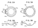
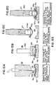
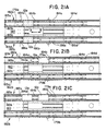
- Figures 2(a) and 2(b) illustrate respective top plan and side views of an embodiment of a concave or front curve, mold half 131 useful in the production of a contact lens by the polymerization of a polymerizable composition in a mold assembly composed of two complementary front and back curve mold halves.
- the front mold half 131 is preferably formed of polystyrene but could be any suitable thermoplastic polymer which is transparent to visible and ultraviolet light to allow irradiation therethrough with light to promote the subsequent polymerization of a soft contact lens.
- a suitable thermoplastic such as polystyrene also has other desirable qualities such as being moldable to surfaces of optical quality at relatively low temperatures, having excellent flow characteristics and remaining amorphous during molding, not crystallizing, and having minimal shrinkage during cooling.
- the front mold half 131 defines a central curved section with an optical quality concave surface 134a, which has a circular circumferential parting edge 136 extending therearound.
- the parting edge 136 shown in Figure 2(b), is desirable to form a well defined and uniform plastic radius parting line (edge) for the subsequently molded soft contact lens.
- a generally parallel convex surface 134b is spaced from the concave surface 134a, and an annular essentially uniplanar flange 131a is formed extending radially outwardly from the surfaces 134a,b in a plane normal (perpendicular) to the axis (of rotation) of the concave surface 134a.
- the concave surface 134a has the dimensions of the front curve (power curve) of a contact lens to be produced by the front mold half, and is sufficiently smooth such that the surface of a contact lens formed by polymerization of a polymerizable composition in contact with the surface is of optically acceptable quality.
- the front mold half is designed with a thinness (typically 0.8 mm) and rigidity effective to transmit heat therethrough rapidly and to withstand prying forces applied to separate the mold half from the mold assembly during de-molding.
- the flange 131a facilitates handling and positioning of the mold half as described in greater detail below.
- the front mold half 131 further defines a generally triangular tab 131c projecting from one side of the flange that is essentially uniplanar, lies in a plane parallel to the plane of flange 131a, and, is integral therewith.
- Figures 3(a) and 3(b) illustrate respectively top elevational and side views of one embodiment of a convex or back curve, mold half 133.
- the back curve mold half is designed with all of the same design considerations mentioned above with respect to the front mold half 131 as will be described in greater detail below.
- the back mold half 133 is also preferably formed of polystyrene but could be any suitable thermoplastic such as those mentioned hereinbelow which is transparent to visible and ultraviolet light.
- the back curve mold half 133 defines a central curved section with an optical quality convex surface 137a, a generally parallel concave surface 137b spaced from the convex surface 137a, and an annular essentially uniplanar flange 133a formed extending radially outwardly from the surfaces 137a and 137b in a plane normal to the axis (of rotation) of concave surface 137b to facilitate handling and positioning of the mold half.
- the convex surface 137a has the somewhat diminished dimensions of the rear curve (which rests upon the cornea of the eye) of a contact lens to be produced by the back mold half, and is sufficiently smooth such that the surface of a contact lens formed by polymerization of a polymerizable composition in contact with the surface is of optically acceptable quality.
- the back curve is designed with a sag of 5.6 mm and a thickness of 0.6 mm to result in a gap of 1.5 mm - 3.0 mm ( Figure 5(b)) between an assembled back curve and front curve flange areas 133a, 130a, respectively, which allows mechanical means to remove the back curve mold halves from the front curve mold halves after polymerization.
- the back curve is thin enough to effectively transmit heat therethrough rapidly and thick enough to withstand prying forces applied to separate the mold half from the mold assembly during demolding.
- Each of the front curve mold halves 131 and back curve mold halves 133 described above, are manufactured in respective injection mold assemblies 20 and 30 described generally above with reference to Figure 1, and in further detail in EP-A-0686486, the disclosure of which is incorporated by reference herein.
- the manufacture of the mold halves employs a heated mold (to ensure the flow rate does not decrease nor shear stresses increase) which introduces a molten mold material through a hot runner system to at least one (and preferably up to eight) mold cavity(ies).
- the mold material is a thermoplastic polymer such as polystyrene, polyvinyl chloride, polyethylene, polypropylene, copolymers of styrene with acrylonitrile and/or butadiene, acrylates such as poly methyl methacrylate, polyacrylonitrile, polyamides, polyesters, and the like. Polystyrene is preferred.
- Each mold cavity defines an optical quality curved surface and also a second noncritical curved surface for the mold half as described above.
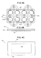
- FIG. 4(a) A top view of a production line pallet 12a for carrying production lens mold halves is shown illustrated in Figure 4(a). It should be understood that pallets 12a,b are interchangeable in that they may accommodate either front curve or back curve contact lens mold halves.
- the production line pallet 12a is formed of aluminum and may be up to 60 mm in width and 120 mm in length. In another embodiment, the pallet 12a may be formed of stainless steel and may be 80 mm in width and 160 mm in length.
- each pallet 12a contains a plurality of recesses 130b for receiving front curve mold halves, back curve mold halves, or, contact lens mold assemblies 139 each comprising a complimentary pair of front 131 and back 133 curve mold halves which define the shape of the final desired lens.
- One such mold assembly 139 is shown seated within a recess 130b of the pallet in Figure 5(b).
- the depth of each recess 130b is greater than the 5.6 mm sag of a back curve lens mold and is sufficient to ensure that the convex optical quality surface of a back curve lens mold half seated within the recess does not come into contact with the concave surface of the pallet recess.
- The-contact lenses are formed by placing an amount of polymerizable composition, generally on the order of about 60 ⁇ liters (microliters) in each front curve (concave) mold half 131 seated within a pallet recess 130b at the filling/mold assembly apparatus 50.
- the desired amount depends on the dimensions (i.e., the diameter and thickness) of the desired lens, and the cavity formed between the front curve and back curve mold portions.
- the back curve (convex) mold half 133 is placed onto the polymerizable composition 132 with the first and second mold halves aligned so that their axes of rotation are collinear and the respective flanges 131a, 133a are parallel.
- the mold halves 131,133 are carried in an annular recess 130a which receives and supports the annular flange 131a of the front curve mold half and the annular flange 133a of the back curve mold half.
- the depth of the annular recesses 130a is sufficient to ensure that the annular flange portion of each lens mold half preferably lies planar with, or, slightly below, the pallet surface so that the mold halves do not protrude above the pallet surface when seated in the recesses.
- the pallets 12a,b also have a plurality of oriented recesses 130c which receive the triangular tab portion 131c,133c of the seated front curve mold half 131 or back curve mold half 133, respectively, to provide a predefined angular position thereof.
- the recesses 130c are designed to prevent movement of the normally seated mold half within each recess up to within +/- 0.1 mm.
- the triangular tab 133c of the second or back curve mold half 133 overlies front curve tab 131c to provide a collinear axis of rotation with respect to the two mold halves.
- recesses 130d are additionally provided in the pallet surface for accommodating clips (not shown) that are inserted at the hydration station 89 for removing the front curve mold halves from the pallets 12a as discussed in further detail in EP-A-0686488.
- pallet 12a of the present invention is designed to ensure that a tight vacuum seal may be created with the surface of the pallet during the monomer deposition and contact lens mold assembly phases of the production line facility.
- blind locating bushings 129a and 129b are located at opposite ends of the pallet 12a to enable precise positioning of the pallet within the various assemblies of the production plant. These locating bushings enable a precise registration of the pallet throughout the various assemblies of the contact lens production facility, and, thereby assist in the alignment of a tight vacuum seal to be created at the peripheral outer surface 140 of the pallet during the deposition of polymerizable monomer in the concave portion of the front lens mold half prior to assembling the final mold assembly.
- proximate the center of each pallet 12a is a unique bar code identifier 135 for handling, tracking, and quality control purposes as explained in greater detail in EP-A- 0686901.
- the outer peripheral edges of the pallet 12a define a groove or indentation 28a,b for engaging a complementary guide rail or shoulder for enabling precise registration of the pallet at the demolding apparatus, as will be explained below in greater detail below. Additionally, the grooves 28a,b engage a means (not shown) at the monomer dosing (filling) and mold assembly stations to prevent lifting of the pallet by a residual vacuum when the vacuum that is created on the pallet is removed.
- Each pallet 12a(,12b) includes blind holes 128a and 128b wherein a viewing device, such as a bore scope, may be inserted to enable real time viewing of the contact lens production process at the surface of the pallet.
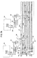
- Figure 7(a) illustrates in detail apparatuses 22 and 24 for transporting respective front curve and back curve mold portions from respective injection mold assemblies 20 and 30 to respective pallets 12a and 12b.
- a detailed description of each injection mold assembly 20 and 30 may be found in EP-A-0687550.
- a detailed description of each transporting assembly 22 and 24 may be found in EP-A-0688648.
- robotic apparatus 22 is provided with a first robotic assembly 15 for removing front curve lens mold articles from injection mold assembly 20, and transporting the articles to a first location; assembly 17 is provided for receiving the front curve lens mold articles from assembly 15 and transporting the articles from the first location to a second location, and robotic assembly 16 is provided for receiving the front curve lens mold articles from assembly 17 and transporting those articles from the second location to an inverting head 38a of inverting device 38 that inverts the orientation of the front curve mold portions carried by the robot 16.
- a clamping mechanism 37 comprising a pair of clamping jaws 37a,b (shown as phantom lines) are located at opposite sides of the conveyor 27 to timely clamp an empty pallet 12a and halt its motion so that the front curve mold halves may be positioned on the pallet by inverting head 38a.
- apparatus 30 shown in Figure 1 is also provided with a first assembly 25 for removing back curve lens mold articles therefrom and transporting the articles to a first location; assembly 28 is provided for receiving the back curve lens mold articles from assembly 25 and transporting the articles from the first location to a second location, and robot assembly 26 is provided for receiving the back curve lens mold articles from assembly 28 and transporting those articles from the second location to a predetermined location along a back curve supply conveyor 29 carrying a back curve lens pallet 12b that has been momentarily paused to receive the back curve lens mold articles from assembly 24.
- a clamping mechanism 36 comprising a pair of clamping jaws 36a,b are located to timely clamp an empty pallet 12b to halt its motion on conveyor 29 while the back curve mold halves are positioned on the pallet by robot assembly 26.
- infeed conveyors 32, front curve 27 and back curve 29 conveyors transports the pallets 12a and molds in a low oxygen environment, which environment is accomplished by enclosing each conveyor in an atmosphere of pressurized nitrogen gas.
- the handling of the pallets and the contact lens mold assemblies throughout the various stations of the production line facility are in nitrogen gas to provide a low oxygen environment for all of the component parts prior to polymerization.
- clamping mechanism 37 consists of one or more pneumatic cylinders 39 that operates to push lower ends 45a,b of clamping jaws 37a,b so the jaws pivot about associated clamping shafts 42a,b to close in and enable respective fixed clamping blocks 37c,d to grip pallet 12a (shown in phantom lines in Figure 6) that is positioned in alignment with the jaws 37a,b.
- the clamping blocks 37c,d of clamping jaws 37a,b are located just above and at opposite sides of the conveyor 27 while the pneumatic cylinder 39 is mounted below the conveyor 27.
- each supply conveyor 27,29 comprises a drive means in the form of a motor driven belts 33a,33b, respectively, which are strong enough to support pallets 12a,b supplied to the sequencing apparatus 40.
- a raised underside section 138 of each pallet 12a,b may be coated with Nedox® or Tufram® so to enable sliding of the pallet when being held above a moving belt by clamping jaws 36,37 or pushed along slide plates at certain processing locations of the plant.
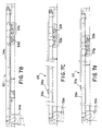
- sequencing pallet conveyor 32 comprises a drive means 34b in the form of a motor driven belt 34a which is strong enough to transport thirty or more paired sets of pallets 12a,12b to the various filling/mold assembly apparatuses 50.
- the motor drive means 34b shown in Figure 7(b) enables the paired sets of pallets carrying respective front and back curve lens mold portions to be smoothly and uniformly transported at a preferred rate of approximately 40 mm/sec (+/- 10 mm/sec) until they are assembled for processing at the filling/mold assembly apparatus 50 explained in detail below.
- Idler rollers 34c and tensioner roller 34d are provided as shown in Figure 7(b) for adjusting the tension of the drive belt 34a, if necessary.
- suitable motor drive means 33c,33d drive respective conveyor belts 33a,33b carrying the respective pallets 12a,12b so that they are smoothly and uniformly transported at a preferred rate of approximately 85 mm/sec (+/- 10 mm/sec) until their motion is terminated at the ends of each conveyor for sequencing as will be explained in further detail below.
- idler rollers 33e and tensioner roller 33f are provided as shown in Figure 7(c) for adjusting the tension of the drive belt 33b of conveyor 29.
- idler rollers 33g and tensioner roller 33h are provided as shown in Figure 7(d) for adjusting the tension of the drive belt 33a of conveyor 29.
- Figure 5(a) illustrates a cross-sectional, front view of a conveyor assembly 27 shown carrying a pallet 12a on conveyor belt 33a. It is understood that the view of Figure 5(a) may apply to any of the other above-described conveyors 29 and 32 carrying pallets.
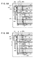
- Figures 7(a) and 8(a) - 8(c) illustrate in detail the sequencing apparatus 40 of pallet system 10 comprising a double cross pusher which positions a pallet 12a from conveyor 27 (containing front curve contact lens mold portions) next to a pallet 12b from supply conveyor 29 (containing back curve contact lens mold portions) for conveyance along the sequencing conveyor 32.
- the double cross pusher 40 is located at the respective ends 27a,29a of each supply conveyor 27, 29 and comprises a first arm 141 and second arm 142 for simultaneously pushing pallets from respective supply conveyors 27 and 29 along track 143 for entry into the main sequencing conveyor 32.
- the first arm 141 and second arm 142 are mounted in parallel on mounting means 145 that is slidable along track 147 in both directions as indicated by the double arrows in Figure 7(a).
- a lifting means 148 which may be pneumatically operated, is provided for raising and lowering the first and second arms 141,142 in a vertical direction above the plane of a horizontally positioned pallet, as will be explained in further detail below. While the arms 141,142 are in a raised position, the mounting means 145 remains slidable along track 147 so that the first and second arms may be retracted while in their raised position and subsequently lowered after reaching their original positions.
- a first step of the sequencing process the forward motion of a pallet 12a from conveyor 27 is terminated at a first position "A", just forward of the first arm 141, as shown in Figure 8(a).
- Forward motion of the pallet 12a is terminated by a pair of upstream clamping jaws 146a,b, that, in a timed fashion, open and close to let one pallet align with the first pusher arm 141 of the double pusher.
- jaws 146a,b are closed, forward motion of the pallet is terminated and a plurality of pallets will accumulate behind the clamped pallet.
- one pallet may be released by opening the clamping jaws 146a,b so that the forward motion of the accumulating pallets on conveyor 27 will push the first lead pallet to a second position indicated as "A'" in Figure 8(a), in alignment with the first pusher arm 141.
- the jaws 146a,b may be immediately closed to clamp the next of the accumulated pallets to prevent its forward motion.
- the opening and closing of the clamping jaws 146a,b may be appropriately timed to enable pallets to be sequentially input to the pusher in an orderly fashion.
- the arms 141,142 of double cross pusher 40 are caused to slide along track 147 in the direction indicated by arrow "C" in Figure 8(a) so that first arm 141 pushes pallet 12a to a second position that is located just forward of second arm 142 position and indicated by arrow "D" in Figure 8(a). It is understood that during any initialization of the sequencer, the second arm 142 did not push any pallet since none were positioned for movement in front of second arm.
- the lifting means is then commanded to raise the first and second arms 141,142 so that the mounting means and the arms may be retracted along track 147 and subsequently lowered back at their original position as shown in Figure 8(a).
- clamping jaws 149a,b close to clamp pallet 12b, while the other pallets on conveyor 29 accumulate behind the clamped pallet.
- the jaws 149a,b are subsequently opened to release the pallet so that the motion of the conveyor 29 pushes the pallet 12b in alignment with the second pusher arm 142.
- the jaws 149a,b are immediately closed to clamp the next of the accumulated pallets to prevent its forward motion. It is readily observed in Figure 8(b) that a pallet 12b carrying back curve contact lens mold portions is now positioned immediately adjacent the previously positioned pallet 12a from the initial step and are both situated at position "D" in alignment with the second arm 142.
- first arm 141 pushes a pallet 12a to the second position (arrow “D") and the second arm 142 pushes the pair of pallets 12a,12b from second position "D" ( Figure 8(b)) to a third position indicated by arrow “E” in Figure 8(c).
- Mounting means 145 and first and second pusher arms 141,142 are represented as phantom lines as shown in Figure 8(e) in their fully extended position on track 147.
- the pusher arms 141,142 are raised so that the mounting means 145 and the arms may be retracted along track 147 and lowered at their original position as shown in Figure 7. While the first and second arms 141,142 are being retracted, a new set of pallets are being loaded at their respective positions. Specifically, a pallet 12a is loaded at position indicated as A' ( Figure 8(b)) and a pallet 12b is loaded at position indicated as B adjacent the previously positioned pallet 12a and the sequence is repeated.
- a third pusher arm 144 operable by pneumatic driving means 148 is activated to push the adjacently situated pair of pallets 12a,12b in the direction indicated by arrow "F" in Figure 8(c), for engagement with the drive belt 34a of conveyor 32.
- the sequence of events described above is repeated so that pairs of pallets 12a,12b are sequentially transported along conveyor 32 to the filling and mold assembly stations of the contact lens production facility, as shown by the phantom lines travelling in the direction of arrow "F" in Figures 1 and 8(c).
- the paired sets of pallets 12a,12b carrying respective front curve and back curve lens molds reach a second sequencing apparatus 55 where their forward motion is diverted for input to the filling apparatus 50.
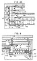
- FIG 9 which is a continuation of Figure 7(a), illustrates the precision pallet handling apparatus 55 for transferring pallets from conveyor 32 to the filling apparatus 50.
- the motion of each pallet 12a,b carrying respective lens mold halves is terminated by a pair of upstream clamping jaws 153a and 153b, in the manner as described above, at position indicated as "A" in front of pusher 154a of ram 154.
- the jaws 153a,b are opened to enable one pallet, for e.g., pallet 12b carrying back curve lens mold halves, to align with pusher 154a of ram 154.
- ram 154 which in the preferred embodiment is driven by pneumatic cylinder unit 158, is timely activated to push the pallet 12b along slide plate 32a for a distance equivalent to the length of the pallet in the direction indicated by arrow "B", to a position in alignment with ram head 157a of ram 157 indicated as position "C” in Figure 9.
- the ram 157 which is also pneumatically driven by suitable means (not shown), is timely activated to push the pallet 12b along track 32b in the direction indicated by arrow "D" for a distance approximately equal to the width of the pallet ⁇ 0.1 mm.
- the sequence of events herein described is continuously repeated to enable precision registration of pallets 12b and 12a to alternately enter filling and dosing apparatus 53 of filling/mold assembly station 50.
- a predetermined amount of the polymerizable monomer or monomer mixture is deposited in a front curve mold half by means of a precision dosing nozzle 242, which is part of the dosing or filling apparatus 53 of station 50.
- the monomer may be dosed in each of the front curve mold halves, carried in the alternating pallets, under vacuum to avoid the possibility of entrapping any gasses between the monomer and the front curve mold half.
- the polymerizable monomer mixture is first degassed to insure that significant dissolved gasses are not present in the monomer inasmuch as dissolved gasses may well form bubbles as the monomer is released from the relatively high pressure of the dosing nozzle 242 to inert atmospheric, N 2 or vacuum conditions surrounding the front curve mold half 131. Additionally the oxygen content of the monomer solution is monitored prior to discharge in the front curve mold cavities.
- approximately 60 ⁇ l (microliters) of polymerizable monomer or monomer mixture is deposited in the front curve mold half to insure that the mold cavity is overdosed, and to avoid the possibility of incomplete molding.
- the excess monomer is removed from the mold cavity in the final step of the assembly of the front and back curve mold halves as will be hereinafter described.
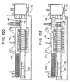
- the filling or dosing station 53 will now be described with respect to Figures 10 and 11, wherein Figures 10 and 11 are partially cross-sectioned views of station 53.
- the monomer is first substantially degassed to avoid the formation of gas bubbles in the dosed monomer, at either the time of dosing or the time of mold assembly, inasmuch as the bubble will induce cavitation of the monomer during polymerization thereby rendering the lens defective and unusable.
- a plurality of monomer supply lines 241 are coupled to an associated discharge nozzle 242, two of which are illustrated in Figure 10 which are suspended directly over the path of the pallet 12a and the individual front curve molds 131.
- the dosing station 53 includes a manifold block 251 for receiving each of the monomer discharge nozzles 242 and a vacuum seal 252 which may be used to cooperate with the outer perimeter 140 of pallet 12a to provide a sealed enclosure that may be evacuated with a vacuum pump so that the deposition of the monomer occurs in a vacuum.
- the manifold block assembly 251 reciprocates with respect to a fixed platform 259 on a pair of tubes or cylinders 253, 254 as will be hereinafter described with respect to Figure 11.
- the dosing module 53 also includes a pair of bore scope tubes 255, 256 which enable inspection of the monomer dosing, if desired, through a bore scope 200.
- the entire deposition module 53 is reciprocated vertically with respect to a fixed support frame 259 and 264 by means of a short stroke pneumatic cylinder 263 mounted on movable frame 262 and to fixed frame 264 by drive rod 263a of pneumatic cylinder 263.
- Vacuum is supplied through the filling or dosing station through manifold 266 and vacuum line 267 to an interior manifold 268 formed in one of the two tubes 253,254.
- the tubes or cylinders 253,254 reciprocate with fixed guide tubes 257,258.
- a vacuum plenum is also formed in the manifold block 251 by means of bore holes 269 and 269(a) which provide vacuum communication between the vacuum manifold 266 and the interior of the dosing station 53 defined by perimeter seal 252 and the pallet 12a.
- a bore scope 200 is illustrated in Figure 11 with an optic probe 201 extending down into the blind holes 128a,b of pallet 12a and manifold block 251.
- a dummy or blind 202 is installed in the other bore scope tube 256 to seal access into the interior vacuum plenum of the assembly station 53 when a bore scope is not in use.
- a pallet 12a is advanced into the dosing station 53 by means of the material handling ram 157 previously discussed with respect to Figure 9.
- the manifold assemoly 251 is reciprocated downwardly by means of pneumatic cylinder 263.
- the sensor assembly 265 may be triggered, thereby opening a valve to draw a vacuum in manifold 266, vacuum line 267, manifold 268 and plenum 269, 269(a). It should be noted that a vacuum is not required for filling or dosing of the mold cavities, but does avoid the possibility of N 2 gas being trapped between the monomer and the front curve mold half.
- the ambient atmosphere surrounding pallet 12a is a low oxygen N 2 environment and evacuation of the chamber is an evacuation of the N 2 gas.
- pumps (not shown) are actuated to deliver a precise dose of 60 ⁇ l to each of the mold cavities 131 illustrated in Figure 10.
- the vacuum is broken in manifold 266 and the manifold assembly 251 is reciprocated upwardly by pneumatic drive means 263 to allow transport of the pallet 12a to the apparatus 56 which coats the mold flange with a mold release surfactant.
- the second apparatus in the station 50 for depositing and assembling the mold parts is a stamping station 56 illustrated in Figure 12(b), and more fully described in EP-A-0686469.
- the annular flange 131a surrounding each front curve mold half of a pallet 12a is stamped via stamp pad 221 with a thin film of surfactant which has been found useful in removing the excess cured monomer displaced from the mold cavity at the time of assembly.
- the excess monomer 132 (when hydroxyethylmethacrylate is used, it is referred to as "HEMA”) is displaced between the flanges 131a and 133a, as illustrated in Figure 12(d) to form a ring 132a of excess HEMA at the time of mold assembly.
- This "HEMA ring” is also cured contemporaneously with the polymerizable monomer or monomer mixture that forms the contact lens 132.
- the excess HEMA ring 132a preferentially adheres to the back curve mold half flange 133a and is removed from the production line at the time the back curve mold half is removed at mold disassembly.
- the mold release surfactant is a polyethylene oxide sorbitan mono-oleate, commercially sold under the trade name "Tween 80".
- the stamping head station 56 includes mounted therein a plurality of stamps 221 each adapted to be moved in vertical reciprocatory movement in a coordinated matter by pistons 222 mounted in the stamping head station 56, wherein the number of stamps 221 is correlated with the number of front curves 131 carried by pallet 12a.
- Each stamp 221 is made of rubber, preferably a silicon/urethane mixture.
- a horizontally shiftable pad member (not shown) which is constituted of a suitable porous material, such as porous polyethylene having an average 10 micron pore size, and which is impregnated with a solution containing a surfactant, the latter of which may be present in a highly concentrated state.
- the upper surface of the pad member is covered by a filter, preferably of nylon, having a mesh size of 1.2 microns so as to act as a metering device and allow only relatively small quantity of surfactant to pass therethrough as the surfactant is wicked from the bottom of the pad member to the top upon the pad member being pressingly contacted by the bottom ends of the stamping heads 221.
- a filter preferably of nylon, having a mesh size of 1.2 microns so as to act as a metering device and allow only relatively small quantity of surfactant to pass therethrough as the surfactant is wicked from the bottom of the pad member to the top upon the pad member being pressingly contacted by the bottom ends of the stamping heads 221.
- the complimentary pair of front 131 and back 133 curve mold halves which define the shape of the final desired lens are used to direct mold the monomer mixture as shown in Figure 5(b).
- the concave front mold half 131 is covered with the back curve mold half 133 under a vacuum to ensure that no air bubbles are trapped between the mold halves.
- the back curve mold half is then brought to rest on the circumferential edge 131c of the concave front mold half to ensure that the resultant lenses are properly aligned and without distortion.
- the provision of tabs 131c and 133c extending from respective sides of each front and back curve mold halves are preferably positioned one over the other as shown in Figure 5(b) during the mold assembly, to facilitate handling thereof.
- Figure 13(a) represents an external elevation view of the assembly module 59
- Figure 13(b) represents a partially cross-sectioned view of the assembly module 59 that is sectioned along two separate axes from section line A - A' for the purposes of illustration.
- the assembly station 59 includes 4 reciprocal pistons 271, two of which are illustrated in the left section of A - A' of Figure 13(b) with back curves attached thereto and two of which are partially visible in the right hand section of A - A' of Figure 13(b) without back curves.
- reciprocating pistons are used to remove eight (8) back curve mold halves from each of the eight locations on pallet 12b for placement upon corresponding front curve lens mold halves.
- the reciprocating pistons 271 are mounted for reciprocation within the vacuum housing 272 and are both carried by and may float within the primary housing 273.
- Each of the three members 271, 272 and 273 reciprocate at various times, both with respect to each other and with respect to the pallet 12b and the pallet 12a containing front mold curves.
- the vacuum manifold housing 272 and the primary housing 273 are mounted for reciprocal movement on cylinders or tubes 274,275 and reciprocate with respect to stationary frame member 276 in response to servo motor 277 which raises and lowers a reciprocating support platform 278.
- Drive motor 277 is fixably attached to frame member 276 by means of guide tubes 279 and 280 and cross-member 281.
- the stationary frame member 276, guide tubes 279,280 and cross-member 281 provide a box frame that is stationary with respect to the reciprocating members of the apparatus.
- the pallet guide rails 282 are also fixed with respect to the stationary fixed platform 276.
- the pallet 12a,b entering the apparatus 59 is advanced through the pallet guide rails 282 by means of the material handling pusher 157 and conveyor 32b previously described and illustrated with respect to Figure 9.
- the vacuum manifold housing 272 and the primary housing 273 reciprocate with respect to each other with the vacuum manifold housing 272 being biased downwardly by a pair of spring members 283,284 positioned on opposite sides of the respective housings.
- the vacuum manifold housing 272 is secured to the primary housing 273 by virtue of a pair of bolts 285,286, one of which is illustrated in cross-section in Figure 13(b) as 285, which are free to reciprocate upwardly into recesses such as recess 287 formed in the primary housing.
- the reciprocating pistons 271 and reciprocating manifold members 288,289 also provide reciprocating guides and support between the two housing members 272,273.
- a pair of bore scope housings 290 and 291 provide access for a bore scope 200 and an optic probe 201 which may be inserted into the assembly cavity for viewing or quality control purposes.
- the bore hole housings 290,291 are closed by a blind 202 in order to allow a vacuum to be drawn within the assembly housing.
- a pallet 12b containing mold half back curves is advanced under the reciprocating pistons 271 as was previously described with respect to Figure 12(c).
- the assembly module 59 is reciprocated downwardly by pneumatic drive motor 277 and cross-member 278 and the reciprocating tubes 274,275 to draw both the vacuum manifold housing and the primary housing downwardly.
- the vacuum manifold housing 272 is biased in its downward position by means of springs 283,284 and the individual reciprocating pistons 271 are biased downwardly by virtue of their mounting within the vacuum manifold housing 272, and by virtue of air pressure maintained within the pneumatic cylinders 293 mounted in the upper portion of primary housing 273 that are pressurized by plenum cavity 203 which connects each of the cylinders 293 to a common air pressure service.
- the reciprocating pistons 271 have engaged the back curve mold halves 131 on pallet 12b and a vacuum is drawn through vacuum manifold in reciprocating piston 271, which has radial bores 294 (Fig.
- annular chamber 295 formed in the vacuum manifold housing 272, two of which are illustrated in Figure 13(b) and 14.
- Each of these annular chamber passageways 295 is interconnected to each other and a common plenum 97 that extends across all 4 annular manifolds 295 on one side of the vacuum manifold housing 272.
- a pair of reciprocating vacuum manifolds 288,289 connect the vacuum manifold 272 with the primary manifold 273, with one of the tubes 288, illustrated in cross-section in Figure 13(b).
- the vacuum manifold 288 reciprocates in bore 298, while vacuum manifold 289 reciprocates in bore 299.
- These reciprocating manifolds are essentially identical, except that they supply vacuum at two different pressures to two different parts of the assembly module.
- each of the back curves is removed from the back curve mold pallet 12b by the vacuum drawn in the reciprocating pistons 271.
- the entire assembly module 70 is then reciprocated upwards in approximately .25 seconds to enable transport of the empty pallet 12b along conveyor 32b out of the assembly module and the insertion of a new pallet 12a that is filled with front curve mold halves, each one of which has been dosed with a monomer at the filling module 53.
- Pallet 12a is advanced into position as previously described with respect to Figure 9, but is registered in precise position by means of tapered registration pins 306,307 which cooperate with the blind registration holes 129a,129b formed on pallet 12a as illustrated in Figure 4(a).
- the taper on pin 306 is sufficient to register the pallet within ⁇ .1 mm for the purposes of precision assembly of the mold halves.
- the assembly cycle begins by reciprocating both the vacuum manifold housing 272 and the primary housing 273 downwardly until a perimeter seal 310 contacts the outer perimeter 140 of the pallet 12b.
- a vacuum switch is actuated by means of a proximity switch adjacent to reciprocating cross-head 278 which actuates a second vacuum source which is drawn through vacuum tube 311 and the interior of reciprocating drive tube 274 to evacuate the chamber formed between the vacuum manifold housing 272 and the platform 12a.
- the vacuum drawn in the two reciprocating drive tubes 274,275 is slightly different, with the vacuum drawn in the tube 275 being slightly greater than that drawn in tube 274 in order to insure that the back curves are retained on the reciprocating pistons 271 prior to their deposition on the monomer and the front curve mold half.
- the pressure drawn in the vacuum manifold around the pallet 12b is on the range of 5 to 7 millibars while the vacuum drawn within the reciprocating pistons 271 is on the order of 3 to 5 millibars.
- the vacuum manifold housing ceases to reciprocate and remains stationary with respect to the pallet 12a.
- the upper or primary housing 273 continues to reciprocate downwardly enabling the back curves to contact the monomer and slowly displace it outwardly to fill the mold cavity as the two mold halves are assembled.
- the vacuum maintained around the housing enables the assembly of the two curves in a more rapid and expeditious manner than if assembled under ambient N 2 pressure.
- the deposition speed may reach as high as 5mm per second, whereas without vacuum, any speed greater than 0.2-1mm per second may result in undue agitation of the monomer and the creation of bubbles which effect and impair the quality of the resultant lens.
- a vacuum is not drawn, it is possible for nitrogen to be trapped between the mold halves or between the monomer and the back curve thereby creating another bubble or puddle which will result in rejection of that lens.
- the optional clamping pressure seats the back curve mold half on the front curve mold half and seats the convex portion of the curve against the parting ring 131c formed on the front curve mold half thereby severing the monomer in the lens blank 132 from the monomer in the excess HEMA ring 132a.
- the vacuum in each of the reciprocating pistons 271 is first broken by opening a valve (not shown) in vacuum line 304. Shortly thereafter, and after a predetermined clamping period and a predetermined clamping pressure, the vacuum between the vacuum manifold housing and the pallet 12a is broken by opening a valve in vacuum line 311.
- the period is .5 to 3 seconds, but preferably is 1.5 seconds.
- the clamping pressure may range from 0.5 to 2 kgm/lens, but, preferably is 1 kgm/lens.
- the pallets 12b that had transported the back curve lens mold portions are empty and are recirculated back to the supply conveyor 29 to pick-up a new set of back curve lens molds from the injection mold facility 30.
- ram assembly 35 having a reciprocating ram 155 and ram head 156 is enabled to push the empty pallet 12b from position indicated as "E” along conveyor 29b in Figure 9 in the direction indicated by arrow "F" where the back curve supply conveyor 29 picks up the pallet 12b for recirculation at the back curve lens mold pick up point.
- a second reciprocating ram 155' and ram head 156' is provided to push, in the direction indicated by arrow "F'" along conveyor 27b, a pallet 12a containing front curve lens molds back to the front curve supply conveyor 27.
- a pallet 12a contains a lens mold assembly having mold halves that are misaligned, that are not seated correctly in a pallet recess, are out of specification in some manner with respect to required residing times at various stations, or, that are detected as not containing the proper amount of monomer mixture in the cavity formed between the mold halves.
- Detection of errors may occur at a variety of locations in the production line, including the filling and mold assembly station 50 and the individual pallets are flagged by quality control device (not shown) so they may be rejected by ram 155' for recirculation.
- the contact lens production line facility includes a suction vent apparatus for removing the mold assemblies from the rejected pallet 12a while being recirculated back to or while on front curve supply conveyor 27.
- the individual pallets 12a containing the eight contact lens mold assemblies leave the filling/mold assembly apparatus 50 on conveyor 32c at a rate of 10 mm/sec (+/- 5 mm/sec) before entering the precure assembly 65 where the front and back curve mold halves are then clamped together in the precure step to displace any surplus monomer from the mold area and to properly align the mold halves by alignment of the mold flanges 131a,133a.
- actinic light preferably from a UV lamp.
- the mold halves are clamped for approximately 40 seconds with 30 seconds of actinic radiation.
- the polymerization mixture has formed a partially polymerized gel, with polymerization initiated throughout the mixture.
- the monomer/solvent mixture is then cured in the UV oven apparatus 75 whereby polymerization is completed in the monomer(s). This irradiation with actinic visible or ultraviolet radiation produces a polymer/solvent mixture in the somewhat diminished shape of the final desired hydrogel lens.
- the conveyor 32c delivers pallets 12a containing a plurality of molds to an accumulating section generally indicated as 168 which assembles a plurality of pallets for a batch operation at the precure assembly 65.
- Accumulator section 168 includes a holding mechanism 166 that is timed by a control device (not shown) to halt a lead pallet in place on the conveyor 32c and enable a predetermined number of subsequent pallets to assemble behind the halted lead pallet to enable batch processing at the precure apparatus.
- twelve pallets are accumulated enabling up to ninety-six (96) mold assemblies to be processed at the precure apparatus 65 in a batch mode for an extended period of time of 30 to 60 seconds while continuously receiving new pallets from the production line at the rate of 1 every 6 to 12 seconds.
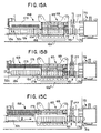
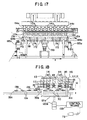
- Figures 15(a) - 15(e) illustrate the sequence for enabling batch processing of the mold assemblies at the mold clamping and precure apparatus 65.
- Figure 15(a) illustrates conveyor 32c delivering twelve pallets 12a containing the plurality of molds to the accumulating section 168.
- lead pallet 12a' is halted behind holding mechanism 166 while the rest of the pallets accumulate therebehind.
- up to twelve pallets indicated generally as 12a” are being processed in the mold clamping and precure assembly 69 while the new set of pallets are being accumulated in accumulating section 168, thus, assuring a continuous flow of pallets into the precure assembly.
- holding mechanism 166 is retracted and the batch pusher arm 173 is extended in the direction indicated by arrow "A" ( Figure 15(a)), to align the twelve pallets on the conveyor 32c conveniently within arms 171a,171b of arm 173 as shown in Figure 15(b).
- a suitable track mechanism 175 and driving means (not shown) is provided for enabling bi-directional and orthogonal horizontal movement of batch pusher arm 173.
- the batch pusher arm 173 is retracted back within track 175 and the batch ram assembly 176 of batch switching apparatus 45 is simultaneously extended to push the other six pallets of the previous batch (12a") to an entry area 177 where the six pallets will be pushed back on to a second conveyor for transport into the UV cycling polymerization apparatus 75.
- the assembly 176 After the batch ram assembly 176 pushes the six pallets into the entry area 177, the assembly 176 is retracted back to its original position as shown in Figure 15(e). After the batch ram assembly 176 is retracted, the batch pusher arm 173 is extended in a horizontal direction indicated by arrow "C" in Figure 15(e) to push the six pallets onto a second conveyor 31b as shown partially hidden in the figure. The batch ram assembly then reciprocates in the opposite direction to arrow "C", to the position as illustrated in Figure 15(a) where it awaits assembly of the next batch of 12 pallets.
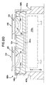
- Figure 16 illustrates a side elevation view of one embodiment of the precure apparatus 65.
- the precure apparatus receives a plurality of pallets having a plurality of contact lens molds therein, from the infeed conveyor 32c.
- the infeed conveyor 32c delivers the pallets 12a and mold assemblies to a low oxygen environment, which environment may be accomplished by pressurizing an enclosure 126 with nitrogen gas. Prior to polymerization, the monomer is susceptible to oxidation from oxygen which results in degradation of the resultant lens.
- the precure assembly 69 of the precure apparatus 65 is partially visible in the breakaway portion of Figure 16. As explained in further detail in EP-A-0686483, the assembly is raised and lowered into engagement with pallets containing contact lens molds by virtue of a pneumatic cylinder 120 which raises and lowers an intermediate support beam 121 and reciprocating shaft members 122 which are journaled for reciprocating support in member 123. After the precure operation, the pallets with contact molds therein are discharged through an airlock mechanism 124 for subsequent cure by heat and cycled actinic radiation.
- Figure 18 is a diagrammatic representation of a portion of the precure assembly 69.
- the assembly 69 includes multiple vertical reciprocal movements, a first one of which is in response to movement from air cylinder 120a and reciprocating beam 121a.
- a plurality of annular clamping means 110 will engage the upper annular flange 133a of each of the mold halves contained within pallets 12a.
- the plurality of annular clamping means 110 are mounted on and travel with a reciprocating platform 111 of the apparatus, and are resiliently mounted therein for a second reciprocal movement along the directions of arrow B illustrated in Figure 18.
- the clamping means 110 are biased within frame 111 by springs 112 (illustrated diagrammatically) which may be an air spring, a helical spring, or, simple weights. As the apparatus is lowered, the clamping means will engage and clamp the first and second mold halves together with the force determined by the spring or weight means 112. When air springs are used, the force will be determined by the amount of pressure provided to the air cylinder (not shown). While clamping means 110 have been illustrated as four members in Figure 18 for illustrative purposes, it is understood that in the embodiment illustrated in Figure 18 there are 96 individual clamping means, with an individual clamping means for each of the mold halves.
- a plurality of actinic light sources 114 Positioned above the clamping apparatus are a plurality of actinic light sources 114 which may be UV lamps.
- a shutter mechanism 115 is opened by air cylinder 116 to enable the actinic light source 114 to initiate polymerization of the polymerizable composition in each of the mold halves 139.
- Shutter 115 has a plurality of openings 113 defined therein and is reciprocal along the x axis as indicated by arrow C in Figure 18 in order to open and close exposure passage ways 117.
- control circuit 100 which controls the duration of the clamping period by the length of time air cylinder 120a is activated to its reciprocal down position.
- Control circuit 100 also controls the amount of radiation received by the molds controlling the duration of the exposure period through operation of shutter 115 and the air cylinder 116.
- the intensity may also be manually adjusted by raising or lowering the lamps 114 with respect to molds 139.
- the amount of force applied by clamping means 110 may be varied from approximately 0.1 Kgf to 2.0 Kgf, and preferably 0.5 to 1.0 Kgf, and is applied to keep the flange 133a of the second convex mold half parallel to the flange 131a of the first concave mold half for the duration of the exposure.
- the clamping weight is applied for 10 to 60 seconds, but typically for a period of 40 seconds by control means 100.
- actinic radiation from UV lamps 114 is applied to the assembled mold and the polymerizable monomer.
- the intensity of the UV light source is 2-4 mW/cm 2 , and this intensity of light is applied for 10 to 50 seconds, but in the preferred embodiment, is applied for 30 seconds. It is understood that different intensities and exposure times could be used, including pulsed and cycled high intensity UV on the order of 10 to 150 mW/cm 2 with exposure times running from 5 to 60 seconds.
- the mold halves are first clamped together for a predetermined period of time, prior to exposure, in order to allow equilibrium to develop between the monomer and the mold cavity, and to allow any excess monomer to be extruded out of the mold cavity into the space between flanges 131a and 133a where it forms a ring of excess monomer 132a, generally referred to as a HEMA ring when hydroxyethylmethacrylate monomer is used, as shown in Figure 5(b).
- the concave front mold cavity includes a sharp annular edge 136 to cleanly contact the convex portion of mold half 133 and thereby separate the contact lens 132 from the HEMA ring 132a.
- the pre-exposure clamping period allows for any excess monomer to migrate from the mold cavity to the HEMA ring, enables the second mold cavity to seat cleanly on parting edge 136, and allows an equilibrium to develop between the mold halves and the monomer.
- the shutter 115 is closed by reciprocating it to the right as illustrated in Figure 18 and the weight is removed by energizing cylinder 120a to lift the precure assembly 69 upwardly by means of push rods 122a.
- the clamping means 110 will be lifted clear of the molds and pallets to enable them to be transported out of the precure means as described above by means of conveyors 31a,b.
- the temperature in the system may be varied from ambient to 50°C.
- the monomer has gone through initiation and some degree of polymerization.
- the resultant lens is in a gel state with some areas of the lens that have the least thickness, i.e., the edge, having a higher degree of polymerization than the body.
- Figure 17 depicts a second embodiment for the batch handling of pallets 12a at the precure station.
- the first embodiment reciprocated the UV lamps and clamping members into and out of engagement with the mold halves and pallets carried by conveyor means 32c.
- the UV lamps are stationary, and the pallets 12a are lifted from the conveyor 32c into engagement with the clamping means for the precure period.
- the clamping means utilized by the embodiment illustrated in Figure 17 utilizes the clamping means 110 previously described with respect to Figure 18.
- a plurality of clamping means 110a are mounted above a roller conveyor illustrated in side view in Figure 17 by rollers 174.
- a plurality of lifting standards 172 are positioned between groups of rollers 174 on centers approximate the width of the pallets 12a.
- a first row of pallets 12a is depicted resting on rollers 174 with adjoining edges of each of the pallets aligned along the top of the lifting standards 172.
- the pallets 12a are aligned in position by means of stop means 189a which is lifted by air cylinder 185a during the loading of the precure apparatus.
- the stop means 189a is reciprocated upwardly, and the requisite number of pallets 12a are advanced into the precure apparatus.
- a second stop means 189b is lifted by air cylinder 185b to define a limit on x axis travel as illustrated in Figure 17.
- a separate air cylinder 185c is used in cooperation with stop means 189a to align the adjoining edges of the pallets 12a above the centers of the lifting standards 172.
- the lifting standards 172 are reciprocated upwardly by means of intermediate support frame 181 and a pair of pneumatic motors generally indicated as 199.
- Each of the clamping members 110a also include a separate independent and resilient spring, as described in aforementioned co-pending patent entitled “Mold Clamping and Precure of a Polymerizable Hydrogel” for driving clamping member 110a and the upper mold half against the lower mold half during the precure period.
- a reciprocating shutter 115a is shifted as illustrated in Figure 17 to align a plurality of openings therein with the central openings formed in the clamping means 110a and thereby enable exposure of the monomer in the mold halves by means of actinic light sources 114a as described generally above with respect to Figure 18.
- the clamping period and the amount of exposure to radiation are controlled by a control circuit in the manner previously described.
- the pallets 12a are reciprocated downwardly to the position illustrated in Figure 17 and advanced by conveyor rollers 174 to a subsequent conveyor as will be described in detail below which transports the pallets to the polymerization apparatus.
- the individual pallets 12a containing the eight contact lens mold assemblies enter the UV-polymerization assembly 75 on two tracks 31a,b as shown in Figure 1.
- the pallets are conveyed at a rate of approximately 5.5 mm/sec.
- Figure 19(a) illustrates the plan view of the UV-polymerization ovens.
- the two halves of the mold are separated during the demolding step leaving the contact lens in the first or front curve mold half, from which it is subsequently removed. It should be mentioned that the front and back curve mold halves are used for a single molding and then discarded or disposed of.
- the pallets containing the polymerized contact lenses in the mold assemblies exit the polymerization oven apparatus 214 and enter a de-molding buffer 76 having an ambient temperature of 30°C to 85°C for preparing the mold assemblies for subsequent de-molding.
- the pallets containing mold assemblies exit the de-mold buffer 76 along two conveyors 31a,31b, and enter into the demold assembly 90.
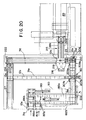
- the pallets are transferred from their conveyors and positioned along a respective transport carrier 182a, 182b of dual walking beam 180.
- each transport carrier 182a,182b comprises a plurality of respective spaced apart push blocks, such as the eight labelled 184a,b,c,d and 186a,b,c,d, that move horizontally to precisely transport a pallet containing mold assemblies to the demold apparatus 90.
- the pallet To position a pallet 12a from conveyor 31a to transport beam 182a of dual walking beam 180, the pallet is first clamped by upstream clamping jaws 186a,b as shown in Figure 20. In a timed manner under control of suitable control means, the pallet is released and positioned on a pair of carrier guide tracks 183a,b between a pair of push blocks, e.g., 184a,184b of carrier 182a as shown in Figure 21(a), for transport through the demolding apparatus 90.
- a pair of carrier guide tracks 183a,b between a pair of push blocks, e.g., 184a,184b of carrier 182a as shown in Figure 21(a) for transport through the demolding apparatus 90.
- FIG. 21(a) - (d) A detailed view of transport carrier 182a(,b) of dual walking beam 180 is shown in Figures 21(a) - (d).
- the transport carrier 182a(,b) includes a reciprocating carrier beam 179a(,b) having plurality of push blocks 184a,b,..etc. (186a,b,..etc.), spaced equally apart on the respective carrier beams 179a(,b) at a distance approximately equal to that of the length of a pallet.
- Each carrier beam 179a,b is mounted for horizontal reciprocating movement in the directions indicated by the double-headed arrow "A-B" in Figure 21(a) for advancing the pallets 12a along respective guide tracks 183a(,b) and 183c(,d) through the demold apparatus, and, is additionally mounted for reciprocating movement in the vertical direction as indicated by double-headed arrow "A'-B'" in Figure 21(d).
- each guide track 183a,b includes a pair of tracking guide rails or shoulders 188a and 188b for mating with respective grooves 28a,b of the pallet as described above.
- the paired set of shoulders 188a,b and respective guide rails notches 28a,b of the pallet keep the pallet precisely aligned as it is being advanced by carrier beam 179a throughout the demold apparatus, and, further prevents any vertical movement of the pallet 12a when the mold assemblies 139 are demolded.
- a push block e.g., block 184a
- the height of a push block is such that it will engage the edge of a pallet when the transport beam 179a is vertically reciprocated to the position indicated by arrow "A'" when advancing the pallet through the demold apparatus 90, and, will disengage the edge of the pallet when carrier beam 179a is vertically retracted to a position indicated by the arrow "B'".
- a pallet 12a is first positioned on the parallel set of tracks 183a,b between the first two push blocks 184a and 184b.
- the transport carrier beam 179a is driven forward in the direction indicated as "C" in Figure 21(b), so that push blocks 184a,b engage pallet 12a to advance its position along the guide tracks 183a,b from its previous position shown in Figure 21(a).
- the pallet 12a shown positioned in Figure 21(a) is now shown as broken lines in an advanced position between push blocks 184a,b in Figure 21(b).
- the transport carrier beam 179a is retracted in a vertical direction beneath the plane of the carrier rails 183a,b so that the carrier beam (and push blocks thereof) may reciprocate horizontally beneath the pallet to its original position in the direction "A" as indicated in Figure 21(a).
- the carrier beam 179a (and push blocks 184a,b,..etc.) is extended vertically to its original position where the push blocks 184a,b engage a newly registered pallet 12a from conveyor 31a, as shown in Figure 21(c). Additionally, the first pallet 12a that had been advanced on carrier rails 183a,b is now engaged between push blocks 184b,c.
- a precise and continuous flow of pallets through the mold separation apparatus 90 is assured.
- the specific mechanisms for enabling reciprocating horizontal and vertical motion of the transport carriers beams 179a,(179b) and push blocks 184a,b,..etc., (186a,b,.. etc.) thereof, will now be described.
- Figure 22 illustrates a partially cut side view of dual walking beam 180 showing transport conveyor 182a.
- the transport carrier beam 179a is mounted by suitable mounting means 197 on track 193 for horizontal reciprocating movement thereupon.
- Motor 191 and suitable drive linkages 192 are provided to precisely control the horizontal movement of the transport carrier beam 179a along the track 193 so as to enable push blocks to engage and advance the pallet along the carrier rails 183a,b.
- the carrier beam 179a is retractable in the vertical direction by a series of pneumatic cylinders, two of which 190a, 190d are shown in the figure.
- the cylinders 190a,d and motor 191 are precisely controlled by control means to simultaneously provide for the reciprocation and retraction of the transport carrier beam.
- the transport carriers of the dual walking beam carries the pallets containing contact lens mold assemblies to the demold apparatus where, preferably, the flange portions of the front curve and back curve mold halves are gripped and pulled away from each other, either in directly opposite directions or through an angle in a prying sort of motion.
- the contact lens mold assembly is first heated moderately to facilitate separation of the polymerized article from the mold half surfaces.
- the demold apparatus 90 includes means for applying a precise amount of heat, which may be in the form of steam or infrared radiation from a lamp or a laser, to the back curve lens mold portion of the contact lens mold assembly, prior to prying apart the back curve mold half from the front curve mold half by a set of pry fingers that are inserted within the gap formed between the overlying flange portions of each mold half of the mold assembly.
- a precise amount of heat which may be in the form of steam or infrared radiation from a lamp or a laser
- the demold assembly 90 includes reciprocating beam 226 carrying two steam discharge assemblies 227a,227b, one assembly for each pallet situated therein by each transport carrier 182a,182b of dual walking beam 180.
- Each steam discharge assembly includes eight steam head nozzles (generally indicated 260) connected to a distribution manifold and a steam heat source (not shown), so that steam may be simultaneously applied to each of the mold assemblies on the pallet.
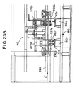
- the reciprocating beam 226 is extended from position indicated "A" in Figure 23(a) to position indicated "A'" in Figure 23(b) so that the steam head units precisely engage their respective mold assemblies for applying steam at a carefully controlled temperature and duration.
- Figure 23(b) shows only steam head assembly 227b in engagement with a pallet 12a.
- a set 230a of pry tool are extended, as indicated by the arrows, for insertion between the 1.5 mm - 3.0 mm gaps formed between the respective front and back curves for each of the four lens molds situated one side of the pallet 12a.
- a set 230b of pry tools are extended for insertion between the gaps formed between the respective front and back curves of each of the four lens molds situated on the opposite side of the pallet 12a.
- each set of pry tools 230a,b are inserted in a manner such that fingers 235 of a bottom set of the pry tools thereof anchors the circumferential or annular rim portion 131c of the front curve of the lens mold to the surface of the pallet, and that fingers 236 of a top set of pry tools by action of pneumatic drive means 221 thereof will vertically separate ( Figure 23(e)) the back curve mold portion of the lens mold from the front curve mold portion without destroying the integrity of the contact lens or either of the mold parts.
- each suction cup assembly 290a,b is mounted for reciprocating movement on beam 226 and each contains eight suction cups (generally indicated as 285) for precise engagement with a corresponding mold assembly on the pallet when the steam discharge assemblies 227a,b are retracted.
- vacuum suction for the suction cup assembly 290b is activated, and the top group of pry tools having fingers 236 are caused to separate from the lower group of pry tools 235 by pneumatic drive means 221 to bias the circumferential edges of each of the back curves 133 of each lens mold away from each of the front curves 131 which retain a respective contact lens therein and are anchored by the lower group of pry fingers 235.
- the back curve lens molds 133 are effectively removed from their respective front curve lens mold portions and retained by individual suction cups 285.
- the upper and lower sets of pry fingers 115,116 are finally retracted laterally in opposite directions indicated by the arrows in Figure 23(e), to allow each pallet 12a now containing up to eight front curve lens mold portions and a respective contact lens therein, to continue along its respective conveyor path, while the suction cups 285 retain the corresponding individual back curve mold portions for disposal.
- the suction cup assembly 290b is retracted to its original position and the vacuum may be removed therefrom so as to release the removed back curve lens mold portions.
- the separated back curve mold parts are dropped in a bin at the retracted position, and evacuated by a vacuum line (not shown) for disposal.
- each pallet containing the front curve mold halves with an exposed polymerized contact lens therein are subsequently transported to a hydration assembly 89 as shown in the conceptual diagram of Figure 1 and in further detail in Figures 20.
- a dual pusher 202 having retractable arms 202a,b is provided to translate the motion of pallets 12a from each transport carrier of dual walking beam 180 to conveyor 31d for transport at a speed of approximately 25 mm/sec to the hydration chamber.
- the integrity of the mold halves contained in the pallets are checked to determine if any errors have occurred, for e.g., if a back curve mold half was not separated from a corresponding front curve mold half.
- the pallet is first clamped between upstream clamping jaws 207a,b where the pallet is appropriately sensed to determine if any error is present. If an error indicating a rejected pallet is found, that particular pallet and the contents therein are transferred from conveyor 31d to recirculating conveyor 31e by suitable pusher assembly 80 as shown in Figure 20.
- the clamping jaws 207a,b release the rejected pallet and the pusher arm 80 pushes the pallet to recirculating conveyor 31e where the rejected pallet is conveyed back to the front curve supply conveyor 27.
- the contact lens production line facility includes a suction vent apparatus (not shown) for removing the mold assemblies from the rejected pallet 12a while being recirculated back to or while on the front curve supply conveyor 27.
- the pallets containing the demolded contact lens assemblies are alternately clamped by clamping jaws 207a,b and are conveyed as pairs by conveyor 31d to transfer pusher assembly 206 for transference to the hydration assembly 89 ( Figure 1).
- the upstream clamping jaws 209a,b Prior to entering the transfer pusher 206, temporarily clamp a pallet to enable a pair of pallets to accumulate therebehind.
- the clamped pallet is released for a time to enable two pallets 12a,12a' to be forwardly conveyed for alignment with reciprocable pusher arm 210 of transfer pusher 206 as shown in Figure 20.
- the transfer pallet 216 is mounted for reciprocating horizontal movement on tracks 218a,b.
- suitable drive means (not shown) enables transfer pallet 216 and plate 219 carrying four pallets to move across tracks 218a,b in the direction indicated by arrow "A" in Figure 24(a) toward the hydration chamber assembly 89 until it reaches the hydration assembly transfer point indicated by the arrow labelled "B" in Figure 24(b) where effective transfer of the front curve mold assemblies containing polymerized contact lenses to the hydration chamber takes place.
- the transfer of the front curve mold assemblies will be explained in detail below and in further detail in EP-A-0686488 mentioned here in above
- a vacuum gripping matrix (not shown) of hydration assembly 89 is actuated to remove up to thirty-two (32) front curve lens mold portions at a time from the four pallets on the transfer pallet 216 and transfer them to an appropriate receiving device located in front of a de-ionized water bath.
- the transfer pallet 216 and plate 219 carrying empty pallets 12a now reciprocates along tracks 218a,b in the direction indicated by arrow "C" in Figure 24(c) back to its original position.
- the empty pallets are removed from plate 219 on to the return conveyor 31f when the incoming set of new pallets containing front curves are pushed onto the plate by pusher arm 210.
- pusher arm 210 pushes a first set of new pallets 12a on the plate 219 to cause the first set of two empty pallets to exit the plate 219 and engage the conveyor 31f for recirculation back to the front curve pick-up point.
- pusher arm 210 pushes a second set of new pallets 12a on the plate 219 which causes the first set of previously positioned new pallets to advance on the plate 219 and enable the second set of two empty pallets to exit the plate 219 and engage the conveyor 31f for recirculation to the front curve supply pick-up point.
- the return conveyor 31f connects with the front curve supply conveyor 27 to return the empty pallets two at a time to the front curve pick-up point.
- Suitable pushing means 222 having reciprocating push arm 224 pushes the pallets onto the supply conveyor 27 where they are conveyed to the front curve injection mold assembly 20 to receive a new set of eight front curve mold halves in the manner described above.
Abstract
Description
- The present application has been divided from European patent application No. 95 303 969.0 (publication No. 0691195) filed on 9th June 1995, the entire original content of which is hereby incorporated herein by reference.
- This invention relates generally to the production of ophthalmic lenses, and, in particular to a pallet system including carriers for receiving contact lens mold halves, and a conveyor system for transporting the carriers containing the mold halves throughout a production facility for automatically producing ophthalmic contact lenses.
- The direct molding of hydrogel contact lenses is disclosed in U.S. Patent 4,495,313 to Larsen, U.S. Patent 4,680,336 to Larsen et al., U.S. Patent 4,565,348 to Larsen, and U.S. Patent 4,640,489 to Larsen et al., the entire disclosures of which are hereby incorporated by reference in this patent application. Essentially, these references disclose an automated contact lens production process wherein each lens is formed by sandwiching a monomer between back curve (upper) and front curve (lower) mold halves. The monomer is polymerized, thus forming a lens, which is then removed from the mold halves and further treated and packaged for consumer use.
- At the present time, automated and semi-automated processes are used in the production of soft contact lens, however, high transport speeds necessary for high production rates are not achievable, partly due to the strict process controls and tight tolerances necessary in the production of high quality contact lenses.
- As disclosed in the above-identified U.S. Patent 4,565,348 to Larsen, a plurality of male mold halves having convex molding surfaces and a plurality of female mold halves having concave molding surfaces are supported on plastic frames during-the soft contact lens production process. One disadvantage to this method is that production costs are increased due to the increased cycle time for molding of the plastic frame and lens mold halves supported thereby. Since the frame is supportive it naturally requires an increased amount of source materials, further adding to the production cost. Additionally, the injection molded frame for carrying the lens mold halves may not provide the proper support as it may be subject to shrinkage and warpage which can interfere with the system integrity. Furthermore, the injection molded frame is not reusable and is eventually discarded after processing, thus, further adding to production costs.
- It would therefore be highly desirable to provide a completely automated production line pallet system that uses a series of re-usable pallets of sturdy construction to carry contact lens mold halves throughout a contact lens manufacturing facility to thereby eliminate the need for an injection molded support frame for said mold halves.
- It would also be highly desirable to provide a completely automated production line pallet system that uses a series of re-usable pallets of sturdy construction to reduce lens mold production cycle time and minimize production costs.
- It would additionally be highly desirable to incorporate a completely automated production line pallet system for automatically transporting in a fast and efficient manner contact lens mold portions on a pallet throughout a contact lens manufacturing facility that includes filling, mold assembly, pre-cure, polymerizing, and de-molding stations.
- It would additionally be desirable to have in a contact lens manufacturing facility, a production line pallet system that facilitates the manufacture of ophthalmic contact lenses at a high production rate.
- Moreover, it would be highly desirable to have in a contact lens manufacturing facility, a production line pallet system wherein a single carrier pallet contains recesses for carrying either front curve lens mold halves or back curve lens mold halves.
- Furthermore, it would be highly desirable to have in a contact lens manufacturing facility, a production line pallet system wherein the carrier pallets for carrying the mold halves includes means for enabling precision location of the pallet within the various stations of the production line facility.
- It would also be highly desirable to provide a conveyor means for transporting the carrier pallets in serial and batch modes throughout the various stations of a contact lens manufacturing facility.
- An object of the present invention to provide a completely automated production line pallet system that uses a series of re-usable pallets each of sturdy construction to carry both contact lens front curve and back curve mold halves throughout a contact lens manufacturing facility and eliminate the need for an injection molded support frame for said mold halves.
- Another object of the invention is to provide a completely automated production line pallet system that uses a series of re-usable pallets of sturdy construction to reduce lens mold production cycle time and minimize production costs.
- It is an object of the present invention to incorporate a completely automated production line pallet system for automatically transporting contact lens mold halves throughout the contact lens filling, precuring, polymerizing, and demolding stations in a contact lens manufacturing facility in a fast and efficient manner.
- It is a further object of the present invention to incorporate an automated production line pallet system in a contact lens manufacturing facility, that facilitates the manufacture of ophthalmic contact lenses at a high production volume.
- Another object of the present invention is to incorporate in a contact lens production line facility, an automated production line pallet system wherein a carrier pallet is provided that can receive either front curve lens mold halves and back curve lens mold halves.
- It is a further object of the present invention to incorporate in a contact lens production line facility, an automated production line pallet system, wherein the carrier pallets that receive and transport respective front curve and back curve lens mold halves are continuously recirculated after the removal of the mold halves therefrom.
- It is yet still a further object of the present invention to incorporate in a contact lens production line facility, an automated production line pallet system wherein a carrier pallet is provided that includes means for enabling precise positioning of the pallet at one or more stations within the facility.
- It is still another object of the present invention to incorporate in a contact lens production facility, an automated production line pallet system that transports carrier pallets in either serial and batch modes, depending upon the processing station, and provides means for enabling pallets to switch from serial to batch mode prior to entering specific processing stations, and means for enabling pallets to switch from batch mode back to serial mode after exiting specific processing stations.
- Yet still another object of the present invention is to provide an automated production line pallet system in a contact lens manufacturing facility, wherein the pallet system includes means for interleaving pallets containing front curve lens mold halves with pallets containing back curve lens mold halves prior to deposition of monomer solution in the front curve lens mold and the formation of the contact lens mold assembly.
- Yet even another object of the instant invention is to provide an automated production line pallet system in a contact lens manufacturing facility that incorporates bar code identification means enabling specific pallet rejection for enhanced quality control and production efficiency.
- Moreover, another object of the present invention is to provide an automated production line pallet system in a contact, lens manufacturing facility, wherein the pallet system is enclosed in a nitrogen environment throughout various portions of the facility.
- Yet another object of the present invention is to provide an automated production line pallet system in a contact lens manufacturing facility, wherein a carrier pallet is provided that includes means for enabling deposition of material to front curve lens mold halves and the assembly of front curve and back curve lens mold halves to create a mold assembly in a vacuum environment.
- It is still yet another object of the present invention to provide an automated production line pallet system in a contact lens manufacturing facility, wherein the pallet carriers enable the support of individual contact lens mold halves without the need for additional matrix or frame to connect the mold halves.
- Moreover, it is still yet another object of the present invention to provide an automated production line pallet system in a contact lens manufacturing facility, wherein the pallet carriers are provided with individual recesses of predetermined depth that enable protection of lens mold half optical surfaces.
- The above objects are achieved by a contact lens production line pallet system that transports the contact lens mold materials throughout the facility for producing ophthalmic lenses. Specifically, the contact lens production line pallet system includes a pallet for carrying one or more contact lens mold assemblies throughout a contact lens production line, the pallet having one or more first recesses formed in a surface thereof for receiving either a first mold half or a complementary second mold half, the first and second mold halves when placed together constituting an individual contact lens mold assembly. A conveyor means for transporting the pallet from station to station throughout the production line facility is also provided, wherein a locating means is formed in the pallet surface for enabling precise positioning of the pallet at one or more stations in the production line facility.
- Further benefits and advantages of the invention will become apparent from a consideration of the following detailed description given with reference to the accompanying drawings, which specify and show preferred embodiments of the invention.
- The foregoing objects and advantages of the present invention for a contact lens production line pallet system may be more readily understood by one skilled in the art with reference being had to the following detailed description of several preferred embodiments thereof, taken in conjunction with the accompanying drawings wherein like elements are designated by identical reference numerals throughout the several views, and in which:
- Figure 1 is a diagrammatic top view of the production line pallet system constructed according to the present invention;
- Figures 2(a) and 2(b) are respectively top and side cross-sectional views of one embodiment of a front curve (female) mold half of a contact lens mold assembly;
- Figures 3(a) and 3(b) are respectively top and side cross-sectional views of one embodiment of a back curve (male) mold half of a contact lens mold assembly;
- Figure 4(a) is a top plan view of a
production line pallet 12a (12b) of the present invention. - Figures 4(b) and 4(c) are respective side and
bottom views of the
production line pallet 12a (or 12b) of Figure 4(a). - Figure 5(a) is a front, cross-sectional view of
a
production line pallet 12a (or 12b) carried along a conveyor belt of the instant invention. - Figure 5(b) is a detailed view of a contact
lens mold assembly 139 comprising complementary first and second mold halves 131,133 situated in a recess of aproduction line pallet 12a. - Figure 6 is a front, cross-sectional view of the preferred clamping mechanism 37 used to temporarily halt motion of a pallet along a conveyor;
- Figure 7(a) illustrates in
detail apparatuses conveyors - Figure 7(b) illustrates the drive belt and drive
motor assembly for sequenced
pallet conveyor 32. - Figure 7(c) :illustrates the drive belt and drive
motor assembly for back
curve supply conveyor 29. - Figure 7(d) illustrates the drive belt and drive
motor assembly for front
curve supply conveyor 27. - Figures 8(a) - 8(c) illustrate the
sequencing apparatus 40 for positioning apallet 12a containing front curves adjacent apallet 12b containing back curves for interleaved conveyance onsequencing conveyor 32; - Figure 9 illustrates the
apparatus 55 for transferring pallets fromconveyor 32 to the filling/mold assembly apparatus 50; - Figure 10 is a partially cross-sectioned side view of the filling station used for depositing a predetermined amount of monomer in each of the mold cavities.
- Figure 11 is a diagrammatic and partially cross-sectioned
illustration of the dosing or
filling station 53 illustrating the vacuum interconnections to the reciprocating filling module. - Figure 12(a) - 12(d) is a diagrammatic and illustrated flow diagram of the filling/mold assembly apparatus.
- Figure 12(e) is a block diagram flow chart illustrating conceptually the sequence of steps for monomer filling and contact lens mold assembly.
- Figure 13(a) is a diagrammatic side view of the
exterior of the
mold assembly module 59 of the filling/assembly station 50. - Figure 13(b) is a partially cross-sectioned side view of the assembly module illustrated in Figure 13(a).
- Figure 14 is a diagrammatic and partially cross-sectioned
illustration of the
assembly station 59 illustrating the vacuum supplies for the reciprocating assembly station. - Figures 15(a) - 15(e) illustrate the sequence
for enabling batch processing of mold assemblies at the
mold clamping and
precure apparatus 65; - Figure 16 is a partially cut away elevation view
of
pallet conveyor 32c transporting pallets through precure andmold clamping apparatus 65; - Figure 17 is a side elevational view of a second
embodiment for handling pallets at the precure and
mold clamping apparatus 65 illustrated in Figure 11; - Figure 18 is a diagrammatic and schematic
illustration of the
mold clamping apparatus 69 of precure andmold clamping apparatus 65; - Figure 19(a) illustrates the plan view of the UV-polymerization ovens where two tracks of pallets containing lenses are polymerized.
- Figure 19(b) illustrates the plan view of the demold buffer for adjusting the ambient temperature of the mold assemblies prior to demolding.
- Figure 20 illustrates the back end of the
production line pallet system showing the sequence for
transferring pallets from dual conveyors 31a,b to the
demold assembly, and the sequence for transferring pallets
from conveyor 31d to the
transfer apparatus 215 for transfer to the hydration chamber. - Figures 21(a) - 21(c) illustrate the sequence
for advancing pallets on
transport carriers 182a,b ofdual walking beam 180, at a demolding station that requires precise registration of pallets. - Figure 21(d) illustrates a pallet advancing
along
carrier guide tracks 183a,b and guided bynotches 188a,b. - Figure 22 illustrates a partially cut side view
of
dual walking beam 180. - Figure 23(a) illustrates a front elevational
view of the
demolding apparatus 90. - Figure 23(b) illustrates a front elevational
view of the steam heat assembly applying steam heat to a
pallet 12a carrying mold assemblies. - Figures 23(c) - 23(e) illustrate the sequence for separating the back curve mold half from the front curve mold half and the demolding apparatus used therefor.
- Figures 24(a) - 24(c) illustrate the sequence
for transferring pallets containing polymerized contact
lens to the
hydration apparatus 89. -
- Referring to Figure 1, there is shown a contact lens production
line pallet system 10 constructed according to the present invention. As will be described in further detail below, thepallet system 10 generally comprises: aninjection mold assembly 20 for manufacturing contact lens thermoplastic front curve mold halves and aninjection mold assembly 30 for manufacturing contact lens thermoplastic back curve mold portions; the front curveinjection mold assembly 20 including anapparatus 22 for transporting up to eight front curve mold portions at a time from theinjection mold assembly 20 to apallet 12a positioned adjacent afirst pallet conveyor 27 and the back curveinjection mold assembly 30 including anapparatus 24 for transporting up to eight back curve mold portions at a time within apallet 12b positioned adjacent to asecond pallet conveyor 29; asequencing apparatus 40 for situating apallet 12a containing front curve mold portions adjacent apallet 12b containing a corresponding number of complementary back curve mold portions onto a sequencedpallet conveyor 32 wholly contained in a low oxygen environment comprising atunnel 46 of inert N2 gas, where thepallets pallet 12b containing back curve halves first, followed immediately thereafter by apallet 12a loaded with front curve mold halves, into the filling andmold assembly stations 50 sequentially at the rate of approximately 1 pallet each 6 seconds. As illustrated in Figure 1 and the conceptual flow diagram of Figure 12(e), the filling/mold assembly station 50 generally includes: afirst apparatus 53 for depositing, in an optional vacuum environment, a polymerizable compound (monomer mixture) for forming a contact lens in the concave portion of each front curve lens mold portion inpallet 12a; asecond apparatus 56 for depositing a surfactant along an annular rim portion of the front curve for facilitating the later removal of the back curve mold portion and the cured excess monomer (HEMA ring) from the front curve mold portion in amold separation apparatus 90 located downstream of the fillingapparatus 50; and, athird apparatus 59 for assembling the individual contact lens mold assemblies which consists of simultaneously placing each back curve lens mold frompallet 12b on an associated front curve lens mold located onconveyor pallet 12a in an oriented configuration. The simultaneous placing of each back curve lens mold frompallet 12b on an associated front curve lens mold onconveyor pallet 12a takes place in a vacuum environment. Additionally, as shown in Figure 1, after the back curves are removed from thesecond pallet 12b, a pallet recirculatingram assembly 35 pushes the emptyback curve pallets 12b back to the original backcurve supply conveyor 29 for receipt of a new set of back curve lens mold portions frominjection mold assembly 30. - As illustrated in Figure 1, the
pallets 12a containing completed mold assemblies exit the filling/mold assembly stations 50 and are conveyed alongconveyor 32c to aprecure chamber 65 where the monomer solution contained in each mold assembly is partially cured into a viscous or soft gel-like state and where the front and back curve lens molds are subject to a predetermined pressure to further define the contact lens edges, and, to eliminate decentration. - After exiting the
precure chamber 65, the pallets containing the precured lenses are transported alongconveyor 32c to apolymerization chamber 75 where the precured lenses contained in the individual mold assemblies are fully polymerized in UV light ovens to form the contact lens blank. As shown in Figure 1, the sequencedpallet conveyor 32c is split into two conveyors, 31a and 31b, to enable a longer residence time in the polymerization chamber as the mold assemblies are polymerized.Pusher apparatus 45 is used to direct the travel of a predetermined amount of pallets containing the mold assemblies fromconveyor 32c to each of the two conveyors 31a,b. - After the polymerizable compound in each of the mold assemblies are polymerized to form a contact lens blank in the
polymerization chamber 75, the pallets travel through ade-mold buffer area 76 providing temperature adjustment to the mold assemblies exiting the ovens, and along adual walking beam 180 to a back end of thepallet system 10 that includes amold separation apparatus 90 where the back curve lens mold halves of the mold assemblies are automatically separated from the front curve lens mold halves to expose the polymerized contact lens for conveyance to the downstream hydration station (not shown). After the demold process,pusher assembly 210 pushes a series ofpallets 12a on to a reciprocatingtransfer pallet apparatus 215 which conveys the pallets to ahydration assembly 89. At the hydration assembly, the front curve lens mold portions containing polymerized contact lens therein are simultaneously removed from their respective pallets and placed in an appropriate hydration chamber (not shown) so that each contact lens may be hydrated prior to packaging. The transfer apparatus subsequently returns the empty pallets back toconveyor 31f where apusher assembly 222 transfers the empty first pallets back toconveyor 27 where they are transported to receive a new batch of front curve lens mold portions frominjection mold assembly 20. - Referring to the drawings in detail, Figures 2(a) and 2(b) illustrate respective top plan and side views of an embodiment of a concave or front curve,
mold half 131 useful in the production of a contact lens by the polymerization of a polymerizable composition in a mold assembly composed of two complementary front and back curve mold halves. Thefront mold half 131 is preferably formed of polystyrene but could be any suitable thermoplastic polymer which is transparent to visible and ultraviolet light to allow irradiation therethrough with light to promote the subsequent polymerization of a soft contact lens. A suitable thermoplastic such as polystyrene also has other desirable qualities such as being moldable to surfaces of optical quality at relatively low temperatures, having excellent flow characteristics and remaining amorphous during molding, not crystallizing, and having minimal shrinkage during cooling. - As shown in Figure 2(a), the
front mold half 131 defines a central curved section with an optical qualityconcave surface 134a, which has a circularcircumferential parting edge 136 extending therearound. Theparting edge 136, shown in Figure 2(b), is desirable to form a well defined and uniform plastic radius parting line (edge) for the subsequently molded soft contact lens. A generally parallel convex surface 134b is spaced from theconcave surface 134a, and an annular essentiallyuniplanar flange 131a is formed extending radially outwardly from thesurfaces 134a,b in a plane normal (perpendicular) to the axis (of rotation) of theconcave surface 134a. Theconcave surface 134a has the dimensions of the front curve (power curve) of a contact lens to be produced by the front mold half, and is sufficiently smooth such that the surface of a contact lens formed by polymerization of a polymerizable composition in contact with the surface is of optically acceptable quality. The front mold half is designed with a thinness (typically 0.8 mm) and rigidity effective to transmit heat therethrough rapidly and to withstand prying forces applied to separate the mold half from the mold assembly during de-molding. Theflange 131a facilitates handling and positioning of the mold half as described in greater detail below. Thefront mold half 131 further defines a generallytriangular tab 131c projecting from one side of the flange that is essentially uniplanar, lies in a plane parallel to the plane offlange 131a, and, is integral therewith. - Figures 3(a) and 3(b) illustrate respectively top elevational and side views of one embodiment of a convex or back curve,
mold half 133. The back curve mold half is designed with all of the same design considerations mentioned above with respect to thefront mold half 131 as will be described in greater detail below. Theback mold half 133 is also preferably formed of polystyrene but could be any suitable thermoplastic such as those mentioned hereinbelow which is transparent to visible and ultraviolet light. The backcurve mold half 133 defines a central curved section with an optical qualityconvex surface 137a, a generally parallelconcave surface 137b spaced from theconvex surface 137a, and an annular essentiallyuniplanar flange 133a formed extending radially outwardly from thesurfaces concave surface 137b to facilitate handling and positioning of the mold half. Theconvex surface 137a has the somewhat diminished dimensions of the rear curve (which rests upon the cornea of the eye) of a contact lens to be produced by the back mold half, and is sufficiently smooth such that the surface of a contact lens formed by polymerization of a polymerizable composition in contact with the surface is of optically acceptable quality. The back curve is designed with a sag of 5.6 mm and a thickness of 0.6 mm to result in a gap of 1.5 mm - 3.0 mm (Figure 5(b)) between an assembled back curve and frontcurve flange areas - Each of the front curve mold halves 131 and back curve mold halves 133 described above, are manufactured in respective
injection mold assemblies - A top view of a
production line pallet 12a for carrying production lens mold halves is shown illustrated in Figure 4(a). It should be understood thatpallets 12a,b are interchangeable in that they may accommodate either front curve or back curve contact lens mold halves. In the preferred embodiment shown in Figure 4(a), theproduction line pallet 12a is formed of aluminum and may be up to 60 mm in width and 120 mm in length. In another embodiment, thepallet 12a may be formed of stainless steel and may be 80 mm in width and 160 mm in length. - As shown in Figure 4(a), each
pallet 12a contains a plurality ofrecesses 130b for receiving front curve mold halves, back curve mold halves, or, contactlens mold assemblies 139 each comprising a complimentary pair offront 131 and back 133 curve mold halves which define the shape of the final desired lens. Onesuch mold assembly 139 is shown seated within arecess 130b of the pallet in Figure 5(b). The depth of eachrecess 130b is greater than the 5.6 mm sag of a back curve lens mold and is sufficient to ensure that the convex optical quality surface of a back curve lens mold half seated within the recess does not come into contact with the concave surface of the pallet recess. The-contact lenses are formed by placing an amount of polymerizable composition, generally on the order of about 60 µliters (microliters) in each front curve (concave)mold half 131 seated within apallet recess 130b at the filling/mold assembly apparatus 50. The desired amount depends on the dimensions (i.e., the diameter and thickness) of the desired lens, and the cavity formed between the front curve and back curve mold portions. Then, the back curve (convex)mold half 133 is placed onto thepolymerizable composition 132 with the first and second mold halves aligned so that their axes of rotation are collinear and therespective flanges - The mold halves 131,133 are carried in an
annular recess 130a which receives and supports theannular flange 131a of the front curve mold half and theannular flange 133a of the back curve mold half. As shown in Figure 5(b), the depth of theannular recesses 130a is sufficient to ensure that the annular flange portion of each lens mold half preferably lies planar with, or, slightly below, the pallet surface so that the mold halves do not protrude above the pallet surface when seated in the recesses. This enables mechanical pry fingers of thede-mold assembly 90 to unobtrusively enter the 1.5 mm - 3.0 mm gap created between the annular flange portions of each mold half of themold assembly 139, as will be discussed in further detail below, and further enables a bottom set of pry fingers to restrain each front curvelens mold half 131 of the mold assembly against the pallet surface during removal of the back curve mold halves at the de-molding station. Additionally, theannular recesses 130a are provided below the pallet surface so that a quality control laser scanner (not shown) scanning the pallet surface may easily detect any skewed lens mold half that protrudes above the pallet surface. In addition to therecesses pallets 12a,b also have a plurality of orientedrecesses 130c which receive thetriangular tab portion curve mold half 131 or backcurve mold half 133, respectively, to provide a predefined angular position thereof. Therecesses 130c are designed to prevent movement of the normally seated mold half within each recess up to within +/- 0.1 mm. Thetriangular tab 133c of the second or backcurve mold half 133 overliesfront curve tab 131c to provide a collinear axis of rotation with respect to the two mold halves. - As shown in Figure 4(a), recesses 130d are additionally provided in the pallet surface for accommodating clips (not shown) that are inserted at the
hydration station 89 for removing the front curve mold halves from thepallets 12a as discussed in further detail in EP-A-0686488. - As illustrated in Figures 4(a) - 4(c),
pallet 12a of the present invention is designed to ensure that a tight vacuum seal may be created with the surface of the pallet during the monomer deposition and contact lens mold assembly phases of the production line facility. As will be explained in further detail below,blind locating bushings pallet 12a to enable precise positioning of the pallet within the various assemblies of the production plant. These locating bushings enable a precise registration of the pallet throughout the various assemblies of the contact lens production facility, and, thereby assist in the alignment of a tight vacuum seal to be created at the peripheral outer surface 140 of the pallet during the deposition of polymerizable monomer in the concave portion of the front lens mold half prior to assembling the final mold assembly. As shown in Figure 4(a), proximate the center of eachpallet 12a is a uniquebar code identifier 135 for handling, tracking, and quality control purposes as explained in greater detail in EP-A- 0686901. - As further shown in Figures 4(b) and 4(c), the outer peripheral edges of the
pallet 12a define a groove orindentation 28a,b for engaging a complementary guide rail or shoulder for enabling precise registration of the pallet at the demolding apparatus, as will be explained below in greater detail below. Additionally, thegrooves 28a,b engage a means (not shown) at the monomer dosing (filling) and mold assembly stations to prevent lifting of the pallet by a residual vacuum when the vacuum that is created on the pallet is removed. Eachpallet 12a(,12b) includesblind holes 128a and 128b wherein a viewing device, such as a bore scope, may be inserted to enable real time viewing of the contact lens production process at the surface of the pallet. - Figure 7(a) illustrates in
detail apparatuses injection mold assemblies respective pallets injection mold assembly assembly - Generally,
robotic apparatus 22 is provided with a firstrobotic assembly 15 for removing front curve lens mold articles frominjection mold assembly 20, and transporting the articles to a first location;assembly 17 is provided for receiving the front curve lens mold articles fromassembly 15 and transporting the articles from the first location to a second location, androbotic assembly 16 is provided for receiving the front curve lens mold articles fromassembly 17 and transporting those articles from the second location to an inverting head 38a of invertingdevice 38 that inverts the orientation of the front curve mold portions carried by therobot 16. This inversion is necessary because therobotic assembly 16 is handling the front curve mold portions at their non-optical (convex) side and the front curve mold portions must therefore be inverted to enable the non-optical surface of each mold to be placed in thepallet 12a that has been momentarily paused to receive the front curve lens mold articles fromassembly 22. - Each of the pallets is momentarily paused on
conveyor belts jaws 37a,b (shown as phantom lines) are located at opposite sides of theconveyor 27 to timely clamp anempty pallet 12a and halt its motion so that the front curve mold halves may be positioned on the pallet by inverting head 38a. - In the preferred embodiment,
apparatus 30 shown in Figure 1 is also provided with afirst assembly 25 for removing back curve lens mold articles therefrom and transporting the articles to a first location; assembly 28 is provided for receiving the back curve lens mold articles fromassembly 25 and transporting the articles from the first location to a second location, and robot assembly 26 is provided for receiving the back curve lens mold articles from assembly 28 and transporting those articles from the second location to a predetermined location along a backcurve supply conveyor 29 carrying a backcurve lens pallet 12b that has been momentarily paused to receive the back curve lens mold articles fromassembly 24. In the preferred embodiment shown in Figures 6 and 7, aclamping mechanism 36 comprising a pair of clampingjaws 36a,b are located to timely clamp anempty pallet 12b to halt its motion onconveyor 29 while the back curve mold halves are positioned on the pallet by robot assembly 26. It should be mentioned that the process of positioning front and back curve mold portions from their respective injection mold assemblies occurs in a low oxygen, and preferably, a nitrogen environment. Additionally,infeed conveyors 32,front curve 27 andback curve 29 conveyors transports thepallets 12a and molds in a low oxygen environment, which environment is accomplished by enclosing each conveyor in an atmosphere of pressurized nitrogen gas. As will be explained below, the handling of the pallets and the contact lens mold assemblies throughout the various stations of the production line facility are in nitrogen gas to provide a low oxygen environment for all of the component parts prior to polymerization. - The operation of the preferred embodiment of clamping mechanism 37 (and 36) will now be described in view of Figure 6. It should be mentioned that the operation of all clamping mechanisms hereinafter disclosed, is essentially the same as the following description of the preferred embodiment. Specifically, the clamping mechanism 37 consists of one or more
pneumatic cylinders 39 that operates to push lower ends 45a,b of clampingjaws 37a,b so the jaws pivot about associated clamping shafts 42a,b to close in and enable respectivefixed clamping blocks 37c,d to grippallet 12a (shown in phantom lines in Figure 6) that is positioned in alignment with thejaws 37a,b. As illustrated in the Figure 6, the clamping blocks 37c,d of clampingjaws 37a,b are located just above and at opposite sides of theconveyor 27 while thepneumatic cylinder 39 is mounted below theconveyor 27. - To transport the pallets, each
supply conveyor belts pallets 12a,b supplied to thesequencing apparatus 40. As illustrated in Figure 4(b), a raisedunderside section 138 of eachpallet 12a,b may be coated with Nedox® or Tufram® so to enable sliding of the pallet when being held above a moving belt by clampingjaws 36,37 or pushed along slide plates at certain processing locations of the plant. - As shown in Figure 7(b) sequencing
pallet conveyor 32 comprises a drive means 34b in the form of a motor drivenbelt 34a which is strong enough to transport thirty or more paired sets ofpallets mold assembly apparatuses 50. The motor drive means 34b shown in Figure 7(b), enables the paired sets of pallets carrying respective front and back curve lens mold portions to be smoothly and uniformly transported at a preferred rate of approximately 40 mm/sec (+/- 10 mm/sec) until they are assembled for processing at the filling/mold assembly apparatus 50 explained in detail below.Idler rollers 34c andtensioner roller 34d are provided as shown in Figure 7(b) for adjusting the tension of thedrive belt 34a, if necessary. In a similar fashion, as shown in Figures 7(c) and 7(d), suitable motor drive means 33c,33d, driverespective conveyor belts respective pallets idler rollers 33e andtensioner roller 33f are provided as shown in Figure 7(c) for adjusting the tension of thedrive belt 33b ofconveyor 29. Similarly,idler rollers 33g andtensioner roller 33h are provided as shown in Figure 7(d) for adjusting the tension of thedrive belt 33a ofconveyor 29. - Figure 5(a) illustrates a cross-sectional, front view of a
conveyor assembly 27 shown carrying apallet 12a onconveyor belt 33a. It is understood that the view of Figure 5(a) may apply to any of the other above-describedconveyors - Figures 7(a) and 8(a) - 8(c) illustrate in detail the
sequencing apparatus 40 ofpallet system 10 comprising a double cross pusher which positions apallet 12a from conveyor 27 (containing front curve contact lens mold portions) next to apallet 12b from supply conveyor 29 (containing back curve contact lens mold portions) for conveyance along thesequencing conveyor 32. Thedouble cross pusher 40 is located at the respective ends 27a,29a of eachsupply conveyor first arm 141 andsecond arm 142 for simultaneously pushing pallets fromrespective supply conveyors track 143 for entry into themain sequencing conveyor 32. As illustrated in Figure 7(a), thefirst arm 141 andsecond arm 142 are mounted in parallel on mountingmeans 145 that is slidable alongtrack 147 in both directions as indicated by the double arrows in Figure 7(a). A lifting means 148, which may be pneumatically operated, is provided for raising and lowering the first and second arms 141,142 in a vertical direction above the plane of a horizontally positioned pallet, as will be explained in further detail below. While the arms 141,142 are in a raised position, the mounting means 145 remains slidable alongtrack 147 so that the first and second arms may be retracted while in their raised position and subsequently lowered after reaching their original positions. - In a first step of the sequencing process, the forward motion of a
pallet 12a fromconveyor 27 is terminated at a first position "A", just forward of thefirst arm 141, as shown in Figure 8(a). Forward motion of thepallet 12a is terminated by a pair ofupstream clamping jaws 146a,b, that, in a timed fashion, open and close to let one pallet align with thefirst pusher arm 141 of the double pusher. Whenjaws 146a,b are closed, forward motion of the pallet is terminated and a plurality of pallets will accumulate behind the clamped pallet. At the appropriate time, one pallet may be released by opening the clampingjaws 146a,b so that the forward motion of the accumulating pallets onconveyor 27 will push the first lead pallet to a second position indicated as "A'" in Figure 8(a), in alignment with thefirst pusher arm 141. Thejaws 146a,b may be immediately closed to clamp the next of the accumulated pallets to prevent its forward motion. The opening and closing of the clampingjaws 146a,b may be appropriately timed to enable pallets to be sequentially input to the pusher in an orderly fashion. - After appropriate sensing, and, as controlled by a computer or a programmable logic controller, the arms 141,142 of
double cross pusher 40 are caused to slide alongtrack 147 in the direction indicated by arrow "C" in Figure 8(a) so thatfirst arm 141 pushespallet 12a to a second position that is located just forward ofsecond arm 142 position and indicated by arrow "D" in Figure 8(a). It is understood that during any initialization of the sequencer, thesecond arm 142 did not push any pallet since none were positioned for movement in front of second arm. The lifting means is then commanded to raise the first and second arms 141,142 so that the mounting means and the arms may be retracted alongtrack 147 and subsequently lowered back at their original position as shown in Figure 8(a). - The description hereinbelow demarcates where steady state sequencing operations begin. As shown in Figure 8(b), after retracting first and second arms 141,142 to their original position, or, preferably, while the arms are in their raised position while being retracted, a
new pallet 12a carrying front curve lens mold portions fromconveyor 27 is positioned at the vacated first position (indicated by arrow A') in the manner described above. Simultaneously therewith, the forward motion of apallet 12b carrying back curve contact lens mold portions from backcurve supply conveyor 29 is terminated at a position "B" as indicated in Figure 8(b). The process for aligning apallet 12b carrying back curve lens mold portions at position B is essentially similar as described above with respect topallet 12a. In a timed manner, clampingjaws 149a,b close to clamppallet 12b, while the other pallets onconveyor 29 accumulate behind the clamped pallet. Thejaws 149a,b are subsequently opened to release the pallet so that the motion of theconveyor 29 pushes thepallet 12b in alignment with thesecond pusher arm 142. Thejaws 149a,b are immediately closed to clamp the next of the accumulated pallets to prevent its forward motion. It is readily observed in Figure 8(b) that apallet 12b carrying back curve contact lens mold portions is now positioned immediately adjacent the previously positionedpallet 12a from the initial step and are both situated at position "D" in alignment with thesecond arm 142. After appropriate sensing, the arms 141,142 of thedouble cross pusher 40 are again caused to slide alongtrack 147 from their original position in the direction indicated by arrow "C" so thatfirst arm 141 pushes apallet 12a to the second position (arrow "D") and thesecond arm 142 pushes the pair ofpallets track 147. Finally, the pusher arms 141,142 are raised so that the mounting means 145 and the arms may be retracted alongtrack 147 and lowered at their original position as shown in Figure 7. While the first and second arms 141,142 are being retracted, a new set of pallets are being loaded at their respective positions. Specifically, apallet 12a is loaded at position indicated as A' (Figure 8(b)) and apallet 12b is loaded at position indicated as B adjacent the previously positionedpallet 12a and the sequence is repeated. - While the new set of pallets are being loaded at their respective positions, a
third pusher arm 144 operable by pneumatic driving means 148 is activated to push the adjacently situated pair ofpallets drive belt 34a ofconveyor 32. In steady state operation, the sequence of events described above is repeated so that pairs ofpallets conveyor 32 to the filling and mold assembly stations of the contact lens production facility, as shown by the phantom lines travelling in the direction of arrow "F" in Figures 1 and 8(c). The paired sets ofpallets second sequencing apparatus 55 where their forward motion is diverted for input to the fillingapparatus 50. - Figure 9, which is a continuation of Figure 7(a), illustrates the precision
pallet handling apparatus 55 for transferring pallets fromconveyor 32 to the fillingapparatus 50. Specifically, the motion of eachpallet 12a,b carrying respective lens mold halves is terminated by a pair ofupstream clamping jaws pusher 154a ofram 154. When the motion of the first pallet is halted, the alternating series ofpallets 12a,b accumulate therebehind. Thejaws 153a,b are opened to enable one pallet, for e.g.,pallet 12b carrying back curve lens mold halves, to align withpusher 154a ofram 154. Then, ram 154 which in the preferred embodiment is driven bypneumatic cylinder unit 158, is timely activated to push thepallet 12b alongslide plate 32a for a distance equivalent to the length of the pallet in the direction indicated by arrow "B", to a position in alignment withram head 157a ofram 157 indicated as position "C" in Figure 9. Theram 157, which is also pneumatically driven by suitable means (not shown), is timely activated to push thepallet 12b alongtrack 32b in the direction indicated by arrow "D" for a distance approximately equal to the width of the pallet ± 0.1 mm. The sequence of events herein described is continuously repeated to enable precision registration ofpallets dosing apparatus 53 of filling/mold assembly station 50. - As described briefly above and in further view of Figures 10 and 12(a), a predetermined amount of the polymerizable monomer or monomer mixture is deposited in a front curve mold half by means of a
precision dosing nozzle 242, which is part of the dosing or fillingapparatus 53 ofstation 50. The monomer may be dosed in each of the front curve mold halves, carried in the alternating pallets, under vacuum to avoid the possibility of entrapping any gasses between the monomer and the front curve mold half. As described in further detail in EP-A-0686489 , the polymerizable monomer mixture is first degassed to insure that significant dissolved gasses are not present in the monomer inasmuch as dissolved gasses may well form bubbles as the monomer is released from the relatively high pressure of thedosing nozzle 242 to inert atmospheric, N2 or vacuum conditions surrounding the frontcurve mold half 131. Additionally the oxygen content of the monomer solution is monitored prior to discharge in the front curve mold cavities. - In the preferred embodiment of the invention, approximately 60 µl (microliters) of polymerizable monomer or monomer mixture is deposited in the front curve mold half to insure that the mold cavity is overdosed, and to avoid the possibility of incomplete molding. The excess monomer is removed from the mold cavity in the final step of the assembly of the front and back curve mold halves as will be hereinafter described.
- The filling or
dosing station 53 will now be described with respect to Figures 10 and 11, wherein Figures 10 and 11 are partially cross-sectioned views ofstation 53. As previously mentioned, the monomer is first substantially degassed to avoid the formation of gas bubbles in the dosed monomer, at either the time of dosing or the time of mold assembly, inasmuch as the bubble will induce cavitation of the monomer during polymerization thereby rendering the lens defective and unusable. - At the
station 53, a plurality ofmonomer supply lines 241 are coupled to an associateddischarge nozzle 242, two of which are illustrated in Figure 10 which are suspended directly over the path of thepallet 12a and the individualfront curve molds 131. Thedosing station 53 includes amanifold block 251 for receiving each of themonomer discharge nozzles 242 and avacuum seal 252 which may be used to cooperate with the outer perimeter 140 ofpallet 12a to provide a sealed enclosure that may be evacuated with a vacuum pump so that the deposition of the monomer occurs in a vacuum. Themanifold block assembly 251 reciprocates with respect to a fixedplatform 259 on a pair of tubes orcylinders dosing module 53 also includes a pair ofbore scope tubes bore scope 200. - As illustrated in Figure 11, the
entire deposition module 53 is reciprocated vertically with respect to a fixedsupport frame pneumatic cylinder 263 mounted onmovable frame 262 and to fixedframe 264 bydrive rod 263a ofpneumatic cylinder 263. Vacuum is supplied through the filling or dosing station throughmanifold 266 andvacuum line 267 to aninterior manifold 268 formed in one of the two tubes 253,254. The tubes or cylinders 253,254 reciprocate with fixed guide tubes 257,258. A vacuum plenum is also formed in themanifold block 251 by means of bore holes 269 and 269(a) which provide vacuum communication between thevacuum manifold 266 and the interior of thedosing station 53 defined byperimeter seal 252 and thepallet 12a. - A
bore scope 200 is illustrated in Figure 11 with anoptic probe 201 extending down into the blind holes 128a,b ofpallet 12a andmanifold block 251. A dummy or blind 202 is installed in the otherbore scope tube 256 to seal access into the interior vacuum plenum of theassembly station 53 when a bore scope is not in use. - In operation, a
pallet 12a is advanced into thedosing station 53 by means of thematerial handling ram 157 previously discussed with respect to Figure 9. Once in position, themanifold assemoly 251 is reciprocated downwardly by means ofpneumatic cylinder 263. As thevacuum seal 252 on themanifold assembly 251 engages thepallet 12a, thesensor assembly 265 may be triggered, thereby opening a valve to draw a vacuum inmanifold 266,vacuum line 267,manifold 268 andplenum 269, 269(a). It should be noted that a vacuum is not required for filling or dosing of the mold cavities, but does avoid the possibility of N2 gas being trapped between the monomer and the front curve mold half. It should also be noted that the ambientatmosphere surrounding pallet 12a is a low oxygen N2 environment and evacuation of the chamber is an evacuation of the N2 gas. After vacuum has been established within the dosing chamber, pumps (not shown) are actuated to deliver a precise dose of 60 µl to each of themold cavities 131 illustrated in Figure 10. - After the monomer has been dosed into the individual mold cavities, the vacuum is broken in
manifold 266 and themanifold assembly 251 is reciprocated upwardly by pneumatic drive means 263 to allow transport of thepallet 12a to theapparatus 56 which coats the mold flange with a mold release surfactant. - The second apparatus in the
station 50 for depositing and assembling the mold parts is a stampingstation 56 illustrated in Figure 12(b), and more fully described in EP-A-0686469. - In operation, the
annular flange 131a surrounding each front curve mold half of apallet 12a is stamped viastamp pad 221 with a thin film of surfactant which has been found useful in removing the excess cured monomer displaced from the mold cavity at the time of assembly. The excess monomer 132 (when hydroxyethylmethacrylate is used, it is referred to as "HEMA") is displaced between theflanges ring 132a of excess HEMA at the time of mold assembly. This "HEMA ring" is also cured contemporaneously with the polymerizable monomer or monomer mixture that forms thecontact lens 132. - By stamping the front
curve mold flange 131a with a surfactant, theexcess HEMA ring 132a preferentially adheres to the back curvemold half flange 133a and is removed from the production line at the time the back curve mold half is removed at mold disassembly. In the preferred embodiment, the mold release surfactant is a polyethylene oxide sorbitan mono-oleate, commercially sold under the trade name "Tween 80". - The stamping
head station 56 includes mounted therein a plurality ofstamps 221 each adapted to be moved in vertical reciprocatory movement in a coordinated matter bypistons 222 mounted in the stampinghead station 56, wherein the number ofstamps 221 is correlated with the number offront curves 131 carried bypallet 12a. Eachstamp 221 is made of rubber, preferably a silicon/urethane mixture. - Adapted to be positioned in spaced relationship below the lower end of each
stamp 221 when the stamp is in a raised position, is a horizontally shiftable pad member (not shown) which is constituted of a suitable porous material, such as porous polyethylene having an average 10 micron pore size, and which is impregnated with a solution containing a surfactant, the latter of which may be present in a highly concentrated state. The upper surface of the pad member is covered by a filter, preferably of nylon, having a mesh size of 1.2 microns so as to act as a metering device and allow only relatively small quantity of surfactant to pass therethrough as the surfactant is wicked from the bottom of the pad member to the top upon the pad member being pressingly contacted by the bottom ends of the stamping heads 221. - As mentioned above, the complimentary pair of
front 131 and back 133 curve mold halves which define the shape of the final desired lens are used to direct mold the monomer mixture as shown in Figure 5(b). After the dosing and stamping step in the fillingapparatus 50, in which the frontconcave mold half 131 is partially filled with apolymerization mixture 132, the concavefront mold half 131 is covered with the backcurve mold half 133 under a vacuum to ensure that no air bubbles are trapped between the mold halves. The back curve mold half is then brought to rest on thecircumferential edge 131c of the concave front mold half to ensure that the resultant lenses are properly aligned and without distortion. The provision oftabs - The operation of the assembly station of the present invention will be explained with reference to Figures 12(c), 12(d), 13(a) and 14 wherein Figure 13(a) represents an external elevation view of the
assembly module 59 and Figure 13(b) represents a partially cross-sectioned view of theassembly module 59 that is sectioned along two separate axes from section line A - A' for the purposes of illustration. Theassembly station 59 includes 4reciprocal pistons 271, two of which are illustrated in the left section of A - A' of Figure 13(b) with back curves attached thereto and two of which are partially visible in the right hand section of A - A' of Figure 13(b) without back curves. It should be understood that in the preferred embodiment eight reciprocating pistons are used to remove eight (8) back curve mold halves from each of the eight locations onpallet 12b for placement upon corresponding front curve lens mold halves. Thereciprocating pistons 271 are mounted for reciprocation within thevacuum housing 272 and are both carried by and may float within theprimary housing 273. Each of the threemembers pallet 12b and thepallet 12a containing front mold curves. - With reference to Figures 13(b) and 14, the vacuum
manifold housing 272 and theprimary housing 273 are mounted for reciprocal movement on cylinders or tubes 274,275 and reciprocate with respect tostationary frame member 276 in response toservo motor 277 which raises and lowers areciprocating support platform 278.Drive motor 277 is fixably attached to framemember 276 by means ofguide tubes cross-member 281. Thus, thestationary frame member 276, guide tubes 279,280 and cross-member 281 provide a box frame that is stationary with respect to the reciprocating members of the apparatus. Thepallet guide rails 282 are also fixed with respect to the stationaryfixed platform 276. As indicated previously, thepallet 12a,b entering theapparatus 59 is advanced through thepallet guide rails 282 by means of thematerial handling pusher 157 andconveyor 32b previously described and illustrated with respect to Figure 9. - As illustrated in Figure 13(b), the vacuum
manifold housing 272 and theprimary housing 273 reciprocate with respect to each other with the vacuummanifold housing 272 being biased downwardly by a pair of spring members 283,284 positioned on opposite sides of the respective housings. The vacuummanifold housing 272 is secured to theprimary housing 273 by virtue of a pair of bolts 285,286, one of which is illustrated in cross-section in Figure 13(b) as 285, which are free to reciprocate upwardly into recesses such asrecess 287 formed in the primary housing. Likewise, thereciprocating pistons 271 and reciprocating manifold members 288,289 also provide reciprocating guides and support between the two housing members 272,273. - A pair of
bore scope housings bore scope 200 and anoptic probe 201 which may be inserted into the assembly cavity for viewing or quality control purposes. When not in use, the bore hole housings 290,291 are closed by a blind 202 in order to allow a vacuum to be drawn within the assembly housing. - In operation, a
pallet 12b containing mold half back curves is advanced under thereciprocating pistons 271 as was previously described with respect to Figure 12(c). When the pallet is in position, theassembly module 59 is reciprocated downwardly bypneumatic drive motor 277 and cross-member 278 and the reciprocating tubes 274,275 to draw both the vacuum manifold housing and the primary housing downwardly. The vacuummanifold housing 272 is biased in its downward position by means of springs 283,284 and the individualreciprocating pistons 271 are biased downwardly by virtue of their mounting within the vacuummanifold housing 272, and by virtue of air pressure maintained within thepneumatic cylinders 293 mounted in the upper portion ofprimary housing 273 that are pressurized byplenum cavity 203 which connects each of thecylinders 293 to a common air pressure service. Within approximately 0.25 seconds, thereciprocating pistons 271 have engaged the back curve mold halves 131 onpallet 12b and a vacuum is drawn through vacuum manifold inreciprocating piston 271, which has radial bores 294 (Fig. 12(d)) which communicate with anannular chamber 295 formed in the vacuummanifold housing 272, two of which are illustrated in Figure 13(b) and 14. Each of theseannular chamber passageways 295 is interconnected to each other and a common plenum 97 that extends across all 4annular manifolds 295 on one side of the vacuummanifold housing 272. - A pair of reciprocating vacuum manifolds 288,289 connect the
vacuum manifold 272 with theprimary manifold 273, with one of thetubes 288, illustrated in cross-section in Figure 13(b). Thevacuum manifold 288 reciprocates inbore 298, whilevacuum manifold 289 reciprocates in bore 299. These reciprocating manifolds are essentially identical, except that they supply vacuum at two different pressures to two different parts of the assembly module. - As the assembly module reaches its lower most point of travel, each of the back curves is removed from the back
curve mold pallet 12b by the vacuum drawn in thereciprocating pistons 271. The entire assembly module 70 is then reciprocated upwards in approximately .25 seconds to enable transport of theempty pallet 12b alongconveyor 32b out of the assembly module and the insertion of anew pallet 12a that is filled with front curve mold halves, each one of which has been dosed with a monomer at the fillingmodule 53.Pallet 12a is advanced into position as previously described with respect to Figure 9, but is registered in precise position by means of tapered registration pins 306,307 which cooperate with theblind registration holes pallet 12a as illustrated in Figure 4(a). The taper onpin 306 is sufficient to register the pallet within ±.1 mm for the purposes of precision assembly of the mold halves. - The assembly cycle begins by reciprocating both the vacuum
manifold housing 272 and theprimary housing 273 downwardly until a perimeter seal 310 contacts the outer perimeter 140 of thepallet 12b. As contact is made with the perimeter seal, a vacuum switch is actuated by means of a proximity switch adjacent to reciprocating cross-head 278 which actuates a second vacuum source which is drawn throughvacuum tube 311 and the interior of reciprocatingdrive tube 274 to evacuate the chamber formed between the vacuummanifold housing 272 and theplatform 12a. - It should be noted that the vacuum drawn in the two reciprocating drive tubes 274,275 is slightly different, with the vacuum drawn in the
tube 275 being slightly greater than that drawn intube 274 in order to insure that the back curves are retained on thereciprocating pistons 271 prior to their deposition on the monomer and the front curve mold half. In the preferred embodiment, the pressure drawn in the vacuum manifold around thepallet 12b is on the range of 5 to 7 millibars while the vacuum drawn within thereciprocating pistons 271 is on the order of 3 to 5 millibars. - After the vacuum has been established in the vacuum
manifold housing 272, the vacuum manifold housing ceases to reciprocate and remains stationary with respect to thepallet 12a. However, the upper orprimary housing 273 continues to reciprocate downwardly enabling the back curves to contact the monomer and slowly displace it outwardly to fill the mold cavity as the two mold halves are assembled. The vacuum maintained around the housing enables the assembly of the two curves in a more rapid and expeditious manner than if assembled under ambient N2 pressure. When assembled under vacuum, the deposition speed may reach as high as 5mm per second, whereas without vacuum, any speed greater than 0.2-1mm per second may result in undue agitation of the monomer and the creation of bubbles which effect and impair the quality of the resultant lens. Further, if a vacuum is not drawn, it is possible for nitrogen to be trapped between the mold halves or between the monomer and the back curve thereby creating another bubble or puddle which will result in rejection of that lens. - Independent travel of the two manifolds 272,273 is provided since the vacuum
manifold housing 272 no longer reciprocates downwardly after it is seated onpallet 12a. However, the upper primary housing continues to reciprocate downwardly depositing the back curve mold half, and continuing on to thereby completely compresssprings reciprocating pistons 271 float between the back curve mold halves 33 andpneumatic cylinders 293 mounted for reciprocation inmanifold 273, which has been pressurized to a predetermined pressure. Thus, the final clamping pressure is generated on the back curve mold member, as determined by the air pressure maintained inpneumatic cylinders 293, and not by spring members 283,284, or the pressure generated bydrive motor 277. This enables independent reciprocal movement or floating movement of each of thereciprocal pistons 271, while enabling all of the pistons to be pressurized to a common predetermined value. Thus, misalignment of a single mold part will not destroy the entire batch of mold assemblies onpallet 12a. - As was described earlier with respect to Figure 12(d), the optional clamping pressure seats the back curve mold half on the front curve mold half and seats the convex portion of the curve against the
parting ring 131c formed on the front curve mold half thereby severing the monomer in the lens blank 132 from the monomer in theexcess HEMA ring 132a. Also, after the mold halves have been seated, the vacuum in each of thereciprocating pistons 271 is first broken by opening a valve (not shown) invacuum line 304. Shortly thereafter, and after a predetermined clamping period and a predetermined clamping pressure, the vacuum between the vacuum manifold housing and thepallet 12a is broken by opening a valve invacuum line 311. Typically the period is .5 to 3 seconds, but preferably is 1.5 seconds. The clamping pressure may range from 0.5 to 2 kgm/lens, but, preferably is 1 kgm/lens. Thereafter, drivemotor 277 is actuated and theentire assembly module 59 is raised upwardly and reset for a new back curve pickup and a new cycle of operation. - As illustrated in Figure 9, after exiting the
mold assembly module 59 ofapparatus 50, thepallets 12b that had transported the back curve lens mold portions are empty and are recirculated back to thesupply conveyor 29 to pick-up a new set of back curve lens molds from theinjection mold facility 30. To accomplish this, ramassembly 35 having areciprocating ram 155 and ramhead 156 is enabled to push theempty pallet 12b from position indicated as "E" alongconveyor 29b in Figure 9 in the direction indicated by arrow "F" where the backcurve supply conveyor 29 picks up thepallet 12b for recirculation at the back curve lens mold pick up point. Additionally, as shown in Figure 9, a second reciprocating ram 155' and ram head 156' is provided to push, in the direction indicated by arrow "F'" alongconveyor 27b, apallet 12a containing front curve lens molds back to the frontcurve supply conveyor 27. This is done only if the line quality control system indicates that apallet 12a contains a lens mold assembly having mold halves that are misaligned, that are not seated correctly in a pallet recess, are out of specification in some manner with respect to required residing times at various stations, or, that are detected as not containing the proper amount of monomer mixture in the cavity formed between the mold halves. Detection of errors may occur at a variety of locations in the production line, including the filling andmold assembly station 50 and the individual pallets are flagged by quality control device (not shown) so they may be rejected by ram 155' for recirculation. The contact lens production line facility includes a suction vent apparatus for removing the mold assemblies from the rejectedpallet 12a while being recirculated back to or while on frontcurve supply conveyor 27. - As shown in Figure 15(a), the
individual pallets 12a containing the eight contact lens mold assemblies leave the filling/mold assembly apparatus 50 onconveyor 32c at a rate of 10 mm/sec (+/- 5 mm/sec) before entering theprecure assembly 65 where the front and back curve mold halves are then clamped together in the precure step to displace any surplus monomer from the mold area and to properly align the mold halves by alignment of themold flanges UV oven apparatus 75 whereby polymerization is completed in the monomer(s). This irradiation with actinic visible or ultraviolet radiation produces a polymer/solvent mixture in the somewhat diminished shape of the final desired hydrogel lens. - As illustrated in Figure 15(a), the
conveyor 32c deliverspallets 12a containing a plurality of molds to an accumulating section generally indicated as 168 which assembles a plurality of pallets for a batch operation at theprecure assembly 65.Accumulator section 168 includes aholding mechanism 166 that is timed by a control device (not shown) to halt a lead pallet in place on theconveyor 32c and enable a predetermined number of subsequent pallets to assemble behind the halted lead pallet to enable batch processing at the precure apparatus. In the preferred embodiment, twelve pallets are accumulated enabling up to ninety-six (96) mold assemblies to be processed at theprecure apparatus 65 in a batch mode for an extended period of time of 30 to 60 seconds while continuously receiving new pallets from the production line at the rate of 1 every 6 to 12 seconds. - Figures 15(a) - 15(e) illustrate the sequence for enabling batch processing of the mold assemblies at the mold clamping and
precure apparatus 65. Figure 15(a) illustratesconveyor 32c delivering twelvepallets 12a containing the plurality of molds to the accumulatingsection 168. As shown in Figure 15(a),lead pallet 12a' is halted behind holdingmechanism 166 while the rest of the pallets accumulate therebehind. It can be seen from Figure 15(a) that up to twelve pallets indicated generally as 12a", are being processed in the mold clamping andprecure assembly 69 while the new set of pallets are being accumulated in accumulatingsection 168, thus, assuring a continuous flow of pallets into the precure assembly. - After accumulating up to twelve pallets in accumulating
section 168, holdingmechanism 166 is retracted and thebatch pusher arm 173 is extended in the direction indicated by arrow "A" (Figure 15(a)), to align the twelve pallets on theconveyor 32c conveniently withinarms 171a,171b ofarm 173 as shown in Figure 15(b). It is understood that asuitable track mechanism 175 and driving means (not shown) is provided for enabling bi-directional and orthogonal horizontal movement ofbatch pusher arm 173. Once the 12 pallets are aligned between arms 171a,b ofbatch pusher arm 173, the pusher arm is driven in the horizontal direction indicated by arrow "B" as shown in Figure 15(c). The previous set of twelvepallets 12a" that had been undergoing mold clamping and precure are simultaneously pushed out of theprecure assembly 69 by thearm 171b ofbatch pusher 173 as the new sets of pallets are brought in by thebatch pusher 173 as shown in Figure 15(c). In the partially exposed view of the UV polymerization oven in Figure 15(c), six (6) of the previous set (12a") of pallets are pushed onto a conveyor 31a, thus, dividing the set into two batches of six pallets each for entry into the batch UV cycling polymerization apparatus 75 (Figure 1) as described hereinbelow. - As shown in Figure 15(d) after the new batch of twelve pallets are brought into
precure apparatus 65 for mold clamping and precure, thebatch pusher arm 173 is retracted back withintrack 175 and thebatch ram assembly 176 ofbatch switching apparatus 45 is simultaneously extended to push the other six pallets of the previous batch (12a") to anentry area 177 where the six pallets will be pushed back on to a second conveyor for transport into the UVcycling polymerization apparatus 75. - After the
batch ram assembly 176 pushes the six pallets into theentry area 177, theassembly 176 is retracted back to its original position as shown in Figure 15(e). After thebatch ram assembly 176 is retracted, thebatch pusher arm 173 is extended in a horizontal direction indicated by arrow "C" in Figure 15(e) to push the six pallets onto a second conveyor 31b as shown partially hidden in the figure. The batch ram assembly then reciprocates in the opposite direction to arrow "C", to the position as illustrated in Figure 15(a) where it awaits assembly of the next batch of 12 pallets. - Figure 16 illustrates a side elevation view of one embodiment of the
precure apparatus 65. As illustrated in Figure 16, the precure apparatus receives a plurality of pallets having a plurality of contact lens molds therein, from theinfeed conveyor 32c. Theinfeed conveyor 32c delivers thepallets 12a and mold assemblies to a low oxygen environment, which environment may be accomplished by pressurizing anenclosure 126 with nitrogen gas. Prior to polymerization, the monomer is susceptible to oxidation from oxygen which results in degradation of the resultant lens. - The
precure assembly 69 of theprecure apparatus 65 is partially visible in the breakaway portion of Figure 16. As explained in further detail in EP-A-0686483, the assembly is raised and lowered into engagement with pallets containing contact lens molds by virtue of apneumatic cylinder 120 which raises and lowers anintermediate support beam 121 and reciprocatingshaft members 122 which are journaled for reciprocating support inmember 123. After the precure operation, the pallets with contact molds therein are discharged through anairlock mechanism 124 for subsequent cure by heat and cycled actinic radiation. - Figure 18 is a diagrammatic representation of a portion of the
precure assembly 69. Theassembly 69 includes multiple vertical reciprocal movements, a first one of which is in response to movement fromair cylinder 120a andreciprocating beam 121a. As theprecure apparatus 69 is lowered in the direction illustrated by arrow A, a plurality of annular clamping means 110 will engage the upperannular flange 133a of each of the mold halves contained withinpallets 12a. The plurality of annular clamping means 110 are mounted on and travel with a reciprocating platform 111 of the apparatus, and are resiliently mounted therein for a second reciprocal movement along the directions of arrow B illustrated in Figure 18. - As illustrated in Figure 18, the clamping means 110 are biased within frame 111 by springs 112 (illustrated diagrammatically) which may be an air spring, a helical spring, or, simple weights. As the apparatus is lowered, the clamping means will engage and clamp the first and second mold halves together with the force determined by the spring or weight means 112. When air springs are used, the force will be determined by the amount of pressure provided to the air cylinder (not shown). While clamping means 110 have been illustrated as four members in Figure 18 for illustrative purposes, it is understood that in the embodiment illustrated in Figure 18 there are 96 individual clamping means, with an individual clamping means for each of the mold halves.
- Positioned above the clamping apparatus are a plurality of actinic
light sources 114 which may be UV lamps. After the clamping means has engaged the mold halves to clamp them together, ashutter mechanism 115 is opened byair cylinder 116 to enable the actiniclight source 114 to initiate polymerization of the polymerizable composition in each of the mold halves 139.Shutter 115 has a plurality ofopenings 113 defined therein and is reciprocal along the x axis as indicated by arrow C in Figure 18 in order to open and closeexposure passage ways 117. - The operation of the
precure apparatus 69 is set bycontrol circuit 100 which controls the duration of the clamping period by the length oftime air cylinder 120a is activated to its reciprocal down position.Control circuit 100 also controls the amount of radiation received by the molds controlling the duration of the exposure period through operation ofshutter 115 and theair cylinder 116. The intensity may also be manually adjusted by raising or lowering thelamps 114 with respect tomolds 139. - The amount of force applied by clamping
means 110 may be varied from approximately 0.1 Kgf to 2.0 Kgf, and preferably 0.5 to 1.0 Kgf, and is applied to keep theflange 133a of the second convex mold half parallel to theflange 131a of the first concave mold half for the duration of the exposure. The clamping weight is applied for 10 to 60 seconds, but typically for a period of 40 seconds by control means 100. After approximately 10 seconds of weight, actinic radiation fromUV lamps 114 is applied to the assembled mold and the polymerizable monomer. Typically, the intensity of the UV light source is 2-4 mW/cm2, and this intensity of light is applied for 10 to 50 seconds, but in the preferred embodiment, is applied for 30 seconds. It is understood that different intensities and exposure times could be used, including pulsed and cycled high intensity UV on the order of 10 to 150 mW/cm2 with exposure times running from 5 to 60 seconds. - The mold halves are first clamped together for a predetermined period of time, prior to exposure, in order to allow equilibrium to develop between the monomer and the mold cavity, and to allow any excess monomer to be extruded out of the mold cavity into the space between
flanges excess monomer 132a, generally referred to as a HEMA ring when hydroxyethylmethacrylate monomer is used, as shown in Figure 5(b). As mentioned above, the concave front mold cavity includes a sharpannular edge 136 to cleanly contact the convex portion ofmold half 133 and thereby separate thecontact lens 132 from theHEMA ring 132a. The pre-exposure clamping period allows for any excess monomer to migrate from the mold cavity to the HEMA ring, enables the second mold cavity to seat cleanly on partingedge 136, and allows an equilibrium to develop between the mold halves and the monomer. - At the end of the radiation period, the
shutter 115 is closed by reciprocating it to the right as illustrated in Figure 18 and the weight is removed by energizingcylinder 120a to lift theprecure assembly 69 upwardly by means ofpush rods 122a. As theassembly 69 is lifted, the clamping means 110 will be lifted clear of the molds and pallets to enable them to be transported out of the precure means as described above by means of conveyors 31a,b. During the precure time, the temperature in the system may be varied from ambient to 50°C. - At the conclusion of the precure process, the monomer has gone through initiation and some degree of polymerization. The resultant lens is in a gel state with some areas of the lens that have the least thickness, i.e., the edge, having a higher degree of polymerization than the body.
- Figure 17 depicts a second embodiment for the batch handling of
pallets 12a at the precure station. As described above with respect to Figures 16 and 18, the first embodiment reciprocated the UV lamps and clamping members into and out of engagement with the mold halves and pallets carried by conveyor means 32c. In the embodiment illustrated in Figure 17, the UV lamps are stationary, and thepallets 12a are lifted from theconveyor 32c into engagement with the clamping means for the precure period. - The clamping means utilized by the embodiment illustrated in Figure 17 utilizes the clamping means 110 previously described with respect to Figure 18. In this second embodiment, a plurality of clamping means 110a are mounted above a roller conveyor illustrated in side view in Figure 17 by
rollers 174. A plurality of liftingstandards 172 are positioned between groups ofrollers 174 on centers approximate the width of thepallets 12a. In Figure 17, a first row ofpallets 12a is depicted resting onrollers 174 with adjoining edges of each of the pallets aligned along the top of the liftingstandards 172. - The
pallets 12a are aligned in position by means of stop means 189a which is lifted byair cylinder 185a during the loading of the precure apparatus. During loading of the device, the stop means 189a is reciprocated upwardly, and the requisite number ofpallets 12a are advanced into the precure apparatus. When 6 pallets in each row have been advanced, a second stop means 189b is lifted byair cylinder 185b to define a limit on x axis travel as illustrated in Figure 17. Aseparate air cylinder 185c is used in cooperation with stop means 189a to align the adjoining edges of thepallets 12a above the centers of the liftingstandards 172. After the pallets have been aligned, the liftingstandards 172 are reciprocated upwardly by means ofintermediate support frame 181 and a pair of pneumatic motors generally indicated as 199. - The pallets are reciprocated upwardly to the position illustrated at 12a' in Figure 17, in which position they engage the clamping
member 110a as previously described. Each of theclamping members 110a also include a separate independent and resilient spring, as described in aforementioned co-pending patent entitled "Mold Clamping and Precure of a Polymerizable Hydrogel" for driving clampingmember 110a and the upper mold half against the lower mold half during the precure period. - After the pallets and mold halves have been raised by
air cylinders 199 and the first and second mold halves clamped together by means of clamping means 110a, areciprocating shutter 115a is shifted as illustrated in Figure 17 to align a plurality of openings therein with the central openings formed in the clamping means 110a and thereby enable exposure of the monomer in the mold halves by means of actiniclight sources 114a as described generally above with respect to Figure 18. The clamping period and the amount of exposure to radiation are controlled by a control circuit in the manner previously described. - Following the precure of the monomer in
mold assembly 139, thepallets 12a are reciprocated downwardly to the position illustrated in Figure 17 and advanced byconveyor rollers 174 to a subsequent conveyor as will be described in detail below which transports the pallets to the polymerization apparatus. - As described above, after leaving the
precure apparatus 65, theindividual pallets 12a containing the eight contact lens mold assemblies enter the UV-polymerization assembly 75 on two tracks 31a,b as shown in Figure 1. In the UV-polymerization assembly 75, the pallets are conveyed at a rate of approximately 5.5 mm/sec. Figure 19(a) illustrates the plan view of the UV-polymerization ovens. - After the polymerization process is completed, the two halves of the mold are separated during the demolding step leaving the contact lens in the first or front curve mold half, from which it is subsequently removed. It should be mentioned that the front and back curve mold halves are used for a single molding and then discarded or disposed of.
- As illustrated in Figure 19(b) which is a continuation of Figure 19(a), the pallets containing the polymerized contact lenses in the mold assemblies exit the
polymerization oven apparatus 214 and enter ade-molding buffer 76 having an ambient temperature of 30°C to 85°C for preparing the mold assemblies for subsequent de-molding. As shown in Figure 20, the pallets containing mold assemblies exit thede-mold buffer 76 along two conveyors 31a,31b, and enter into thedemold assembly 90. The pallets are transferred from their conveyors and positioned along arespective transport carrier dual walking beam 180. As illustrated in Figures 21(a)-(c), eachtransport carrier demold apparatus 90. - To position a
pallet 12a from conveyor 31a to transportbeam 182a ofdual walking beam 180, the pallet is first clamped by upstream clampingjaws 186a,b as shown in Figure 20. In a timed manner under control of suitable control means, the pallet is released and positioned on a pair ofcarrier guide tracks 183a,b between a pair of push blocks, e.g., 184a,184b ofcarrier 182a as shown in Figure 21(a), for transport through thedemolding apparatus 90. In a similar fashion, to transport apallet 12a from conveyor 31b to transportbeam 182b ofdual walking beam 180, the pallet is first clamped by upstream clamping jaws 187a,b (Figure 20), and then timely positioned on a second pair of carrier guide tracks 183c,d (Figure 21(a)) between a pair of push blocks, e.g., 186a,186b ofcarrier 182b for precision transport through the demolding apparatus. The operation oftransport carrier 182a ofdual walking beam 180 will now be described in further detail with the understanding that the principles and methods underlying the operation apply equally to transportcarrier 182b. - A detailed view of
transport carrier 182a(,b) ofdual walking beam 180 is shown in Figures 21(a) - (d). As shown in Figure 21(a), thetransport carrier 182a(,b) includes areciprocating carrier beam 179a(,b) having plurality ofpush blocks 184a,b,..etc. (186a,b,..etc.), spaced equally apart on therespective carrier beams 179a(,b) at a distance approximately equal to that of the length of a pallet. Eachcarrier beam 179a,b is mounted for horizontal reciprocating movement in the directions indicated by the double-headed arrow "A-B" in Figure 21(a) for advancing thepallets 12a alongrespective guide tracks 183a(,b) and 183c(,d) through the demold apparatus, and, is additionally mounted for reciprocating movement in the vertical direction as indicated by double-headed arrow "A'-B'" in Figure 21(d). - As shown in Figure 21(d), each
guide track 183a,b includes a pair of tracking guide rails orshoulders respective grooves 28a,b of the pallet as described above. The paired set ofshoulders 188a,b and respectiveguide rails notches 28a,b of the pallet keep the pallet precisely aligned as it is being advanced bycarrier beam 179a throughout the demold apparatus, and, further prevents any vertical movement of thepallet 12a when themold assemblies 139 are demolded. The height of a push block, e.g.,block 184a, is such that it will engage the edge of a pallet when thetransport beam 179a is vertically reciprocated to the position indicated by arrow "A'" when advancing the pallet through thedemold apparatus 90, and, will disengage the edge of the pallet whencarrier beam 179a is vertically retracted to a position indicated by the arrow "B'". - As previously mentioned above, as shown in Figures 21(a)-(c), a
pallet 12a is first positioned on the parallel set oftracks 183a,b between the first twopush blocks transport carrier beam 179a is driven forward in the direction indicated as "C" in Figure 21(b), so thatpush blocks 184a,b engagepallet 12a to advance its position along theguide tracks 183a,b from its previous position shown in Figure 21(a). Thus, thepallet 12a shown positioned in Figure 21(a) is now shown as broken lines in an advanced position betweenpush blocks 184a,b in Figure 21(b). Immediately after advancing thepallet 12a, thetransport carrier beam 179a is retracted in a vertical direction beneath the plane of thecarrier rails 183a,b so that the carrier beam (and push blocks thereof) may reciprocate horizontally beneath the pallet to its original position in the direction "A" as indicated in Figure 21(a). - After reciprocating horizontally to its original position, the
carrier beam 179a (and pushblocks 184a,b,..etc.) is extended vertically to its original position where thepush blocks 184a,b engage a newly registeredpallet 12a from conveyor 31a, as shown in Figure 21(c). Additionally, thefirst pallet 12a that had been advanced oncarrier rails 183a,b is now engaged betweenpush blocks 184b,c. By continuous reciprocation of eachtransport carrier beam 179a(,b) ofdual walking beam 180, a precise and continuous flow of pallets through themold separation apparatus 90 is assured. The specific mechanisms for enabling reciprocating horizontal and vertical motion of the transport carriers beams 179a,(179b) and pushblocks 184a,b,..etc., (186a,b,.. etc.) thereof, will now be described. - Figure 22 illustrates a partially cut side view of
dual walking beam 180 showingtransport conveyor 182a. As shown in the Figure 22, thetransport carrier beam 179a is mounted by suitable mounting means 197 ontrack 193 for horizontal reciprocating movement thereupon.Motor 191 andsuitable drive linkages 192 are provided to precisely control the horizontal movement of thetransport carrier beam 179a along thetrack 193 so as to enable push blocks to engage and advance the pallet along thecarrier rails 183a,b. Additionally, as shown in Figure 22, thecarrier beam 179a is retractable in the vertical direction by a series of pneumatic cylinders, two of which 190a, 190d are shown in the figure. Thecylinders 190a,d andmotor 191 are precisely controlled by control means to simultaneously provide for the reciprocation and retraction of the transport carrier beam. - In the preferred embodiment described in detail above, the transport carriers of the dual walking beam carries the pallets containing contact lens mold assemblies to the demold apparatus where, preferably, the flange portions of the front curve and back curve mold halves are gripped and pulled away from each other, either in directly opposite directions or through an angle in a prying sort of motion. Advantageously, the contact lens mold assembly is first heated moderately to facilitate separation of the polymerized article from the mold half surfaces. As explained in further detail in EP-A- 0686490, the
demold apparatus 90 includes means for applying a precise amount of heat, which may be in the form of steam or infrared radiation from a lamp or a laser, to the back curve lens mold portion of the contact lens mold assembly, prior to prying apart the back curve mold half from the front curve mold half by a set of pry fingers that are inserted within the gap formed between the overlying flange portions of each mold half of the mold assembly. - As shown in Figures 23(a) and 23(b), the
demold assembly 90 includesreciprocating beam 226 carrying twosteam discharge assemblies transport carrier dual walking beam 180. Each steam discharge assembly includes eight steam head nozzles (generally indicated 260) connected to a distribution manifold and a steam heat source (not shown), so that steam may be simultaneously applied to each of the mold assemblies on the pallet. To apply heat, thereciprocating beam 226 is extended from position indicated "A" in Figure 23(a) to position indicated "A'" in Figure 23(b) so that the steam head units precisely engage their respective mold assemblies for applying steam at a carefully controlled temperature and duration. Figure 23(b) shows only steamhead assembly 227b in engagement with apallet 12a. - As shown in Figure 23(c), during the time the
steam discharge apparatus 227a,b and thesteam nozzles 260 thereof discharge steam to the back curve of the individual lens molds, aset 230a of pry tool are extended, as indicated by the arrows, for insertion between the 1.5 mm - 3.0 mm gaps formed between the respective front and back curves for each of the four lens molds situated one side of thepallet 12a. Likewise, aset 230b of pry tools are extended for insertion between the gaps formed between the respective front and back curves of each of the four lens molds situated on the opposite side of thepallet 12a. - As further illustrated in Figure 23(c), each set of
pry tools 230a,b are inserted in a manner such thatfingers 235 of a bottom set of the pry tools thereof anchors the circumferential orannular rim portion 131c of the front curve of the lens mold to the surface of the pallet, and thatfingers 236 of a top set of pry tools by action of pneumatic drive means 221 thereof will vertically separate (Figure 23(e)) the back curve mold portion of the lens mold from the front curve mold portion without destroying the integrity of the contact lens or either of the mold parts. - Next, as illustrated in Figure 23(d) after discharging the precision controlled amount of steam, the
steam discharge assemblies 227a,b and thesteam nozzles 260 thereof are retracted by respective steamhead retraction assemblies 272a,b to enable the suctioncup assembly unit 290b to align with thepallet 12a as shown. As shown in Figures 23(a) and 23(b), eachsuction cup assembly 290a,b is mounted for reciprocating movement onbeam 226 and each contains eight suction cups (generally indicated as 285) for precise engagement with a corresponding mold assembly on the pallet when thesteam discharge assemblies 227a,b are retracted. - During the mold separation step illustrated in Figure 23(e), vacuum suction for the
suction cup assembly 290b is activated, and the top group of prytools having fingers 236 are caused to separate from the lower group ofpry tools 235 by pneumatic drive means 221 to bias the circumferential edges of each of the back curves 133 of each lens mold away from each of thefront curves 131 which retain a respective contact lens therein and are anchored by the lower group of pryfingers 235. Thus, the backcurve lens molds 133 are effectively removed from their respective front curve lens mold portions and retained byindividual suction cups 285. - Although not shown, the upper and lower sets of pry fingers 115,116 are finally retracted laterally in opposite directions indicated by the arrows in Figure 23(e), to allow each
pallet 12a now containing up to eight front curve lens mold portions and a respective contact lens therein, to continue along its respective conveyor path, while thesuction cups 285 retain the corresponding individual back curve mold portions for disposal. Specifically, thesuction cup assembly 290b is retracted to its original position and the vacuum may be removed therefrom so as to release the removed back curve lens mold portions. The separated back curve mold parts are dropped in a bin at the retracted position, and evacuated by a vacuum line (not shown) for disposal. - After the mold assemblies have been separated in the
demold apparatus 90, each pallet containing the front curve mold halves with an exposed polymerized contact lens therein, are subsequently transported to ahydration assembly 89 as shown in the conceptual diagram of Figure 1 and in further detail in Figures 20. As shown in Figure 20, adual pusher 202 having retractable arms 202a,b is provided to translate the motion ofpallets 12a from each transport carrier ofdual walking beam 180 to conveyor 31d for transport at a speed of approximately 25 mm/sec to the hydration chamber. Prior to transfer to the hydration chamber, the integrity of the mold halves contained in the pallets are checked to determine if any errors have occurred, for e.g., if a back curve mold half was not separated from a corresponding front curve mold half. The pallet is first clamped between upstream clampingjaws 207a,b where the pallet is appropriately sensed to determine if any error is present. If an error indicating a rejected pallet is found, that particular pallet and the contents therein are transferred from conveyor 31d to recirculating conveyor 31e bysuitable pusher assembly 80 as shown in Figure 20. The clampingjaws 207a,b release the rejected pallet and thepusher arm 80 pushes the pallet to recirculating conveyor 31e where the rejected pallet is conveyed back to the frontcurve supply conveyor 27. As mentioned above, the contact lens production line facility includes a suction vent apparatus (not shown) for removing the mold assemblies from the rejectedpallet 12a while being recirculated back to or while on the frontcurve supply conveyor 27. - If the pallets containing the demolded contact lens assemblies are not rejected, they are alternately clamped by clamping
jaws 207a,b and are conveyed as pairs by conveyor 31d to transferpusher assembly 206 for transference to the hydration assembly 89 (Figure 1). Prior to entering thetransfer pusher 206, theupstream clamping jaws 209a,b temporarily clamp a pallet to enable a pair of pallets to accumulate therebehind. As controlled by the control means, the clamped pallet is released for a time to enable twopallets reciprocable pusher arm 210 oftransfer pusher 206 as shown in Figure 20. Drive means 211 then enablespusher arm 210 to push the two pallets to atransfer apparatus 215, and specifically, apallet 216 having aflat plate portion 219, that accommodates up to two sets of two pallets each for transfer to thehydration chamber 89. After the first set of pallets is placed onplate 219, thepusher arm 210 is reciprocated to its original position (Figure 20) to receive a second set of two pallets. Thepush arm 210 is then enabled to input the second set of two pallets onto theplate 219 oftransfer pusher 216 causing the first set of pallets to advance on the plate. Figure 24(a) shows theflat plate portion 219 oftransfer pallet 216 containing four pallets that have been pushed thereto bypusher arm 210 two pallets at a time. - As shown in Figure 20, the
transfer pallet 216 is mounted for reciprocating horizontal movement ontracks 218a,b. In steady state operation, suitable drive means (not shown) enablestransfer pallet 216 andplate 219 carrying four pallets to move acrosstracks 218a,b in the direction indicated by arrow "A" in Figure 24(a) toward thehydration chamber assembly 89 until it reaches the hydration assembly transfer point indicated by the arrow labelled "B" in Figure 24(b) where effective transfer of the front curve mold assemblies containing polymerized contact lenses to the hydration chamber takes place. The transfer of the front curve mold assemblies will be explained in detail below and in further detail in EP-A-0686488 mentioned here in above - After the
transfer pallet 216 reaches the transfer point a vacuum gripping matrix (not shown) ofhydration assembly 89 is actuated to remove up to thirty-two (32) front curve lens mold portions at a time from the four pallets on thetransfer pallet 216 and transfer them to an appropriate receiving device located in front of a de-ionized water bath. Thetransfer pallet 216 andplate 219 carryingempty pallets 12a now reciprocates alongtracks 218a,b in the direction indicated by arrow "C" in Figure 24(c) back to its original position. The empty pallets are removed fromplate 219 on to thereturn conveyor 31f when the incoming set of new pallets containing front curves are pushed onto the plate bypusher arm 210. Specifically,pusher arm 210 pushes a first set ofnew pallets 12a on theplate 219 to cause the first set of two empty pallets to exit theplate 219 and engage theconveyor 31f for recirculation back to the front curve pick-up point. Likewise,pusher arm 210 pushes a second set ofnew pallets 12a on theplate 219 which causes the first set of previously positioned new pallets to advance on theplate 219 and enable the second set of two empty pallets to exit theplate 219 and engage theconveyor 31f for recirculation to the front curve supply pick-up point. As illustrated in Figure 20 thereturn conveyor 31f connects with the frontcurve supply conveyor 27 to return the empty pallets two at a time to the front curve pick-up point. Suitable pushing means 222 havingreciprocating push arm 224 pushes the pallets onto thesupply conveyor 27 where they are conveyed to the front curveinjection mold assembly 20 to receive a new set of eight front curve mold halves in the manner described above. - While the invention has been particularly shown and described with respect to the preferred embodiments thereof, it will be understood by those skilled in the art that the foregoing and other changes in form and details may be made therein without departing from the spirit and scope of the invention, which should be limited only by the scope of the appended claims.
Claims (6)
- A production line pallet for carrying one or more contact lens molds through a contact lens production line facility for sequential automated processing of said contact lens molds at a plurality of automated stations in said production line, said pallet comprising:wherein said one or more annular recesses formed in said surface may receive either a plurality of front curve contact lens molds or a plurality of complementary back curve contact lens molds prior to assembling said front and back contact lens molds at an automated assembly station in said production line facility.(a) a pallet body;(b) a plurality of first recesses formed in said pallet body for receiving a plurality of individual contact lens molds, said pallet body further defining a plurality of annular second recesses formed in a surface of said pallet body, with each one of said annular recesses surrounding one of said first recesses, each of said contact lens molds defining an annular flange which cooperates with one of said plurality of annular recesses in said pallet surface to provide precise registration of said contact lens mold; and(c) registration means formed in said pallet, said registration means cooperating with said recesses to enable precise automated positioning of said contact lens molds by one or more robotic assemblies at one or more stations in said production line facility;
- The production line pallet according to Claim 1 wherein each of said first recesses includes a recessed tab area (130c) for accommodating a tab portion of said molds to normally seat said molds in a predetermined orientation within a respective first recess.
- The production line pallet according to Claim 1 wherein each of said annular recesses further prevents movement of said molds to within about +0.1 mm and -0.1 mm of its normally seated position.
- The production line pallet according to Claim 2 wherein each said recessed tab area of said first recesses provides torric alignment of said front curve mold and complementary back curve mold when seated in a said first recess.
- The production line pallet according to Claim 1 wherein locating means are provided in said pallet surface which includes one or more locating bushings (129a,129b) at precise locations at said pallet surface.
- The production line pallet according to Claim 5 wherein said one or more locating bushings allow precise positioning of said pallet at said various stations to within about +0.1 mm and -0.1 mm tolerance.
Applications Claiming Priority (3)
| Application Number | Priority Date | Filing Date | Title |
|---|---|---|---|
| US25778694A | 1994-06-10 | 1994-06-10 | |
| US257786 | 1994-06-10 | ||
| EP95303969A EP0691195B1 (en) | 1994-06-10 | 1995-06-09 | Contact lens production line pallet system |
Related Parent Applications (1)
| Application Number | Title | Priority Date | Filing Date |
|---|---|---|---|
| EP95303969A Division EP0691195B1 (en) | 1994-06-10 | 1995-06-09 | Contact lens production line pallet system |
Publications (3)
| Publication Number | Publication Date |
|---|---|
| EP1129842A2 true EP1129842A2 (en) | 2001-09-05 |
| EP1129842A3 EP1129842A3 (en) | 2002-11-06 |
| EP1129842B1 EP1129842B1 (en) | 2005-10-26 |
Family
ID=22977743
Family Applications (5)
| Application Number | Title | Priority Date | Filing Date |
|---|---|---|---|
| EP01201880A Expired - Lifetime EP1129842B1 (en) | 1994-06-10 | 1995-06-09 | Contact lens production line pallet comprising recesses |
| EP95303969A Expired - Lifetime EP0691195B1 (en) | 1994-06-10 | 1995-06-09 | Contact lens production line pallet system |
| EP01201881A Expired - Lifetime EP1142694B1 (en) | 1994-06-10 | 1995-06-09 | Contact lens production line pallet |
| EP00201216A Expired - Lifetime EP1020283B1 (en) | 1994-06-10 | 1995-06-09 | Contact lens production line pallet system |
| EP01201879A Expired - Lifetime EP1123789B1 (en) | 1994-06-10 | 1995-06-09 | Contact lens production line pallet, comprising recesses and bar code identification means |
Family Applications After (4)
| Application Number | Title | Priority Date | Filing Date |
|---|---|---|---|
| EP95303969A Expired - Lifetime EP0691195B1 (en) | 1994-06-10 | 1995-06-09 | Contact lens production line pallet system |
| EP01201881A Expired - Lifetime EP1142694B1 (en) | 1994-06-10 | 1995-06-09 | Contact lens production line pallet |
| EP00201216A Expired - Lifetime EP1020283B1 (en) | 1994-06-10 | 1995-06-09 | Contact lens production line pallet system |
| EP01201879A Expired - Lifetime EP1123789B1 (en) | 1994-06-10 | 1995-06-09 | Contact lens production line pallet, comprising recesses and bar code identification means |
Country Status (12)
| Country | Link |
|---|---|
| US (3) | US5744357A (en) |
| EP (5) | EP1129842B1 (en) |
| JP (1) | JP3920366B2 (en) |
| AT (1) | ATE212902T1 (en) |
| AU (1) | AU709618B2 (en) |
| BR (1) | BR9502733A (en) |
| CA (1) | CA2151340C (en) |
| CZ (1) | CZ147295A3 (en) |
| DE (5) | DE69534554T2 (en) |
| HK (1) | HK1027530A1 (en) |
| IL (1) | IL113693A0 (en) |
| ZA (1) | ZA954817B (en) |
Cited By (1)
| Publication number | Priority date | Publication date | Assignee | Title |
|---|---|---|---|---|
| WO2016189280A1 (en) * | 2015-05-22 | 2016-12-01 | Coopervision International Holding Company, Lp | Method and apparatus for manufacturing contact lenses |
Families Citing this family (65)
| Publication number | Priority date | Publication date | Assignee | Title |
|---|---|---|---|---|
| US5895192C1 (en) | 1994-06-10 | 2001-11-06 | Johnson & Johnson Vision Prod | Apparatus and method for removing and transporting articles from molds |
| US5658602A (en) | 1994-06-10 | 1997-08-19 | Johnson & Johnson Vision Products, Inc. | Method and apparatus for contact lens mold filling and assembly |
| US6752581B1 (en) | 1994-06-10 | 2004-06-22 | Johnson & Johnson Vision Care, Inc. | Apparatus for removing and transporting articles from molds |
| IL113693A0 (en) * | 1994-06-10 | 1995-08-31 | Johnson & Johnson Vision Prod | Contact lens production line pallet system |
| AU710855B2 (en) * | 1995-05-01 | 1999-09-30 | Johnson & Johnson Vision Products, Inc. | Apparatus for removing and transporting articles from molds |
| WO1998036898A1 (en) * | 1997-02-20 | 1998-08-27 | Technology Resource International Corporation | Gasket for lens making |
| US6007229A (en) | 1997-06-05 | 1999-12-28 | Johnson & Johnson Vision Products, Inc. | Rapid robotic handling of mold parts used to fabricate contact lenses |
| EP1055138B1 (en) | 1998-01-16 | 2003-04-02 | Bausch & Lomb Incorporated | Toric axis alignment machine and method |
| US6103148A (en) * | 1998-02-19 | 2000-08-15 | Technology Resources International Corporation | Method for curing a lens-forming fluid |
| US6511311B1 (en) * | 1998-09-30 | 2003-01-28 | Novartis Ag | Lens mold carriers |
| US6241918B1 (en) | 1998-12-28 | 2001-06-05 | Johnson & Johnson Vision Care, Inc. | Process of manufacturing contact lenses in ambient environment |
| US6609041B1 (en) * | 1999-05-05 | 2003-08-19 | Johnson & Johnson Vision Care, Inc. | Method and system for SKU tracking and changeover |
| NL1012002C2 (en) * | 1999-05-07 | 2000-11-09 | O T B Engineering B V | Device for manufacturing disposable lenses. |
| US6638451B1 (en) | 1999-08-31 | 2003-10-28 | Novartis Ag | Plastic casting molds |
| USD434050S (en) * | 1999-12-06 | 2000-11-21 | Technology Resource International Corporation | Gasket for lens making |
| GB0002091D0 (en) * | 2000-01-28 | 2000-03-22 | Aspect Vision Care Ltd | Toric lens manufacture |
| BR0015886A (en) * | 2000-05-26 | 2003-07-01 | Johnson & Johnson Vision Care | Process for Automated Eyeglass Lens Manufacturing |
| US6267587B1 (en) * | 2000-07-06 | 2001-07-31 | Johnson & Johnson Vision Care, Inc. | Thermal curing oven and thermal curing process |
| US6737661B2 (en) * | 2000-08-17 | 2004-05-18 | Novartis Ag | Pre-treatment of molds |
| ATE526135T1 (en) | 2001-03-26 | 2011-10-15 | Novartis Ag | MOLD AND METHOD FOR PRODUCING OPTHALMIC LENSES |
| US6663801B2 (en) | 2001-04-06 | 2003-12-16 | Johnson & Johnson Vision Care, Inc. | Silicon carbide IR-emitter heating device and method for demolding lenses |
| US7241125B2 (en) * | 2001-05-25 | 2007-07-10 | Johnson & Johnson Vision Care, Inc. | Center touch method and apparatus for forming contact lenses |
| US20020195732A1 (en) * | 2001-06-20 | 2002-12-26 | Clark Michael J. | Apparatus and method for identifying ophthalmic molds |
| US7040886B2 (en) * | 2001-08-09 | 2006-05-09 | Johnson & Johnson Vision Care, Inc. | Apparatus and method for handling lens carriers |
| US6708397B2 (en) * | 2001-08-09 | 2004-03-23 | Johnson & Johnson Vision Care, Inc. | Inlay station with alignment assemblies and transfer tubes |
| US7008570B2 (en) * | 2001-08-09 | 2006-03-07 | Stephen Pegram | Method and apparatus for contact lens mold assembly |
| BR0211815A (en) * | 2001-08-09 | 2008-04-08 | Johnson & Johnson | apparatus and method for handling lens carriers |
| US6997693B2 (en) | 2001-10-19 | 2006-02-14 | Novartis Ag | Casting mold half and casting mold for producing contact lenses |
| WO2003058202A2 (en) * | 2001-12-31 | 2003-07-17 | Lockheed Martin Corporation | System and method of detecting, neutralizing, and containing suspected contaminated articles |
| US6729835B2 (en) | 2002-03-28 | 2004-05-04 | Bausch & Lomb Incorporated | Handling assembly for fixturing ophthalmic lenses |
| EP1495380B1 (en) * | 2002-04-12 | 2008-05-14 | Johnson & Johnson Vision Care, Inc. | Method and system for recording data monitored during the manufacture of molded ophthalmic lenses |
| US7177978B2 (en) | 2002-08-10 | 2007-02-13 | Cisco Technology, Inc. | Generating and merging lookup results to apply multiple features |
| DE10249140A1 (en) * | 2002-10-22 | 2004-05-06 | Robert Bosch Gmbh | Dust collector for an electric hand machine tool |
| US20060186564A1 (en) * | 2005-02-22 | 2006-08-24 | Adams Jonathan P | Hydrogel processing |
| US7799249B2 (en) * | 2005-08-09 | 2010-09-21 | Coopervision International Holding Company, Lp | Systems and methods for producing silicone hydrogel contact lenses |
| AU2007211087B2 (en) * | 2006-02-01 | 2011-02-17 | Johnson & Johnson Vision Care, Inc. | Axis control in toric contact lens production |
| US20080217800A1 (en) * | 2007-03-06 | 2008-09-11 | Kernick Edward R | Method for stabilizing lens mold assembly |
| US20080239237A1 (en) * | 2007-03-30 | 2008-10-02 | Ansell Scott F | Molds with thermoplastic elastomers for producing ophthalmic lenses |
| WO2009110883A1 (en) * | 2008-03-03 | 2009-09-11 | Johnson & Johnson Vision Care, Inc. | Method for stabilizing lens mold assembly |
| US20100078837A1 (en) * | 2008-09-29 | 2010-04-01 | Pugh Randall B | Apparatus and method for formation of an energized ophthalmic device |
| US8348424B2 (en) * | 2008-09-30 | 2013-01-08 | Johnson & Johnson Vision Care, Inc. | Variable focus ophthalmic device |
| US9375885B2 (en) * | 2008-10-31 | 2016-06-28 | Johnson & Johnson Vision Care, Inc. | Processor controlled ophthalmic device |
| US9375886B2 (en) * | 2008-10-31 | 2016-06-28 | Johnson & Johnson Vision Care Inc. | Ophthalmic device with embedded microcontroller |
| WO2012064699A1 (en) | 2010-11-10 | 2012-05-18 | Novartis Ag | Method for making contact lenses |
| US20140008824A1 (en) * | 2011-07-28 | 2014-01-09 | Coopervision International Holding Company, Lp | Methods and Systems for Manufacturing Contact Lenses |
| DE202012011690U1 (en) | 2012-03-09 | 2013-03-13 | Schneider Gmbh & Co. Kg | Plant for processing optical lenses |
| ITPD20130209A1 (en) * | 2013-07-26 | 2015-01-27 | Safilo Spa | METHOD OF MANUFACTURING A POLARIZED LENS FOR GLASSES AND LENSES MADE WITH A CALLED METHOD |
| CN104003180B (en) * | 2014-04-29 | 2017-09-12 | 雄华机械(苏州)有限公司 | A kind of pallet recovering mechanism |
| SG11201702861PA (en) * | 2014-11-25 | 2017-06-29 | Novartis Ag | Casting mold for the manufacture of ophthalmic lenses |
| JP6421980B2 (en) * | 2015-03-02 | 2018-11-14 | パナソニックIpマネジメント株式会社 | Imprint device |
| DE102015015040A1 (en) | 2015-11-12 | 2017-05-18 | Schneider Gmbh & Co. Kg | Method, installation and system for processing optical lenses |
| US11041977B2 (en) * | 2015-11-23 | 2021-06-22 | Martin F. Friedberg | Optical printing positional system |
| CN105678853A (en) * | 2016-03-31 | 2016-06-15 | 贵州大学 | Card taking device for automobiles |
| DE102016007837A1 (en) | 2016-05-25 | 2017-11-30 | Schneider Gmbh & Co. Kg | Method and system for processing optical lenses |
| DE102017001680A1 (en) * | 2017-02-22 | 2018-08-23 | Schneider Gmbh & Co. Kg | Plant and method for processing optical lenses |
| CA3054965A1 (en) | 2017-03-16 | 2018-09-20 | Molecular Imprints, Inc. | Optical polymer films and methods for casting the same |
| KR102527262B1 (en) | 2017-10-17 | 2023-04-28 | 매직 립, 인코포레이티드 | Methods and Apparatuses for Casting Polymer Products |
| CN108688053A (en) * | 2018-04-20 | 2018-10-23 | 现代精密自动化(深圳)有限公司 | Kato automated production equipment |
| WO2020081697A1 (en) * | 2018-10-16 | 2020-04-23 | Magic Leap, Inc. | Methods and apparatuses for casting polymer products |
| IT201800010508A1 (en) * | 2018-11-22 | 2020-05-22 | Tecnicoll Srl | Lip stick production machine |
| DE102018132655A1 (en) * | 2018-12-18 | 2020-06-18 | Tvi Entwicklung Und Produktion Gmbh | Transfer plant and transfer process |
| CN113843947B (en) * | 2020-06-25 | 2023-07-28 | 株式会社大镐技术 | Lens and mold transfer system |
| CN113910523A (en) * | 2020-07-09 | 2022-01-11 | 株式会社大镐技术 | Automatic transfer device and lens molding system provided with same |
| TWI736418B (en) * | 2020-09-15 | 2021-08-11 | 英業達股份有限公司 | Multifunctional and lightweight tray for production line |
| CN114131332B (en) * | 2021-12-30 | 2022-09-09 | 惠州市德赛自动化技术有限公司 | Assembling equipment |
Citations (7)
| Publication number | Priority date | Publication date | Assignee | Title |
|---|---|---|---|---|
| GB1092749A (en) * | 1964-12-01 | 1967-11-29 | Pittsburgh Plate Glass Co | A method of producing articles of thermosetting plastics material |
| US4402659A (en) * | 1981-12-30 | 1983-09-06 | American Optical Corporation | Mold clamping fixture |
| US4570782A (en) * | 1980-10-20 | 1986-02-18 | Cargill Detroit Corporation | Non-synchronous rotary manufacturing system |
| EP0227365A2 (en) * | 1985-12-19 | 1987-07-01 | Minnesota Mining And Manufacturing Company | Method and apparatus for making optical devices |
| US4693446A (en) * | 1985-09-20 | 1987-09-15 | Techna Vision, Inc. | Gasket for molding plastic lenses |
| EP0318164A2 (en) * | 1987-10-29 | 1989-05-31 | Techna Vision, Inc. | Lens forming system |
| EP0686489A2 (en) * | 1994-06-10 | 1995-12-13 | JOHNSON & JOHNSON VISION PRODUCTS, INC. | Method and apparatus for contact lens mold filling and assembly |
Family Cites Families (32)
| Publication number | Priority date | Publication date | Assignee | Title |
|---|---|---|---|---|
| US3189971A (en) * | 1963-05-06 | 1965-06-22 | Mansfield Sanitary Inc | System for slip casting hollow ceramic shapes |
| US3506755A (en) * | 1967-06-12 | 1970-04-14 | Goodyear Tire & Rubber | Molding apparatus and methods |
| US3841390A (en) * | 1973-01-29 | 1974-10-15 | F Dibenedetto | Continuous molding machine |
| US4025268A (en) * | 1973-03-22 | 1977-05-24 | Taylor Don A | Articles molding apparatus |
| US3938775A (en) * | 1973-08-20 | 1976-02-17 | Sarofeen George M J | Mold assembly for casting synthetic lenses |
| JPS5087157A (en) * | 1973-12-05 | 1975-07-14 | ||
| US4132518A (en) * | 1977-10-18 | 1979-01-02 | Realite Optical Company | Apparatus for manufacturing plastic lenses |
| JPS5781941A (en) * | 1980-09-13 | 1982-05-22 | Kawasaki Steel Corp | Monitoring device for ingot surface in mold for continuous casting |
| US4640489A (en) * | 1981-04-30 | 1987-02-03 | Mia-Lens Production A/S | Mold for making contact lenses, either the male or female mold sections being relatively more flexible |
| US4565348A (en) * | 1981-04-30 | 1986-01-21 | Mia-Lens Production A/S | Mold for making contact lenses, the male mold member being more flexible than the female mold member |
| US4495313A (en) * | 1981-04-30 | 1985-01-22 | Mia Lens Production A/S | Preparation of hydrogel for soft contact lens with water displaceable boric acid ester |
| US4680336A (en) * | 1984-11-21 | 1987-07-14 | Vistakon, Inc. | Method of forming shaped hydrogel articles |
| IT1177344B (en) * | 1984-11-28 | 1987-08-26 | I O R Ind Ottiche Riunite Spa | PLANT FOR THE AUTOMATIC PRODUCTION OF ORGANIC LENSES |
| JPS61242817A (en) * | 1985-04-19 | 1986-10-29 | Canon Inc | Manufacturing device for plastic lens |
| US4691820A (en) * | 1985-11-18 | 1987-09-08 | Vistakon, Inc. | Package for hydrophilic contact lens |
| JPS63137542A (en) * | 1986-11-28 | 1988-06-09 | Isuzu Motors Ltd | Device for cleaning metallic mold for casting |
| US4913718A (en) * | 1987-11-20 | 1990-04-03 | Canon Kabushiki Kaisha | Molding method for optical element and apparatus therefor |
| US4889664A (en) * | 1988-11-25 | 1989-12-26 | Vistakon, Inc. | Method of forming shaped hydrogel articles including contact lenses |
| US5039459A (en) * | 1988-11-25 | 1991-08-13 | Johnson & Johnson Vision Products, Inc. | Method of forming shaped hydrogel articles including contact lenses |
| JPH02185350A (en) * | 1989-01-12 | 1990-07-19 | Mitsubishi Electric Corp | Work processing device |
| GB8919530D0 (en) * | 1989-08-29 | 1989-10-11 | Mjs Scient Ltd | Machine for making contact lenses |
| US5252056A (en) * | 1990-03-16 | 1993-10-12 | Ciba-Geigy Corporation | Contact lens casting mould |
| JP3055924B2 (en) * | 1990-09-04 | 2000-06-26 | ヤマザキマザック株式会社 | Production system |
| US5094609A (en) * | 1990-04-17 | 1992-03-10 | Vistakon, Inc. | Chamber for hydrating contact lenses |
| US5080839A (en) * | 1990-04-17 | 1992-01-14 | Johnson & Johnson Vision Products, Inc. | Process for hydrating soft contact lenses |
| EP0654721B1 (en) * | 1990-12-18 | 1998-04-22 | Erowa AG | Automatic manufacturing system |
| US5164228A (en) * | 1991-05-20 | 1992-11-17 | Bmc Industries, Inc. | Method of applying scratch-resistant coatings to plastic ophthalmic lenses |
| GB2263085B (en) * | 1992-01-06 | 1995-11-22 | Seikosha Kk | Automatic exchange of sub-molds in injection molding machines |
| US5435943A (en) * | 1994-03-11 | 1995-07-25 | Johnson & Johnson Vision Products, Inc. | Method and apparatus for making an ophthalmic lens |
| IL113693A0 (en) * | 1994-06-10 | 1995-08-31 | Johnson & Johnson Vision Prod | Contact lens production line pallet system |
| US5555504A (en) * | 1994-06-10 | 1996-09-10 | Johnson & Johnson Vision Products, Inc. | Production line tracking and quality control system |
| US5658602A (en) * | 1994-06-10 | 1997-08-19 | Johnson & Johnson Vision Products, Inc. | Method and apparatus for contact lens mold filling and assembly |
-
1995
- 1995-05-11 IL IL11369395A patent/IL113693A0/en unknown
- 1995-06-07 CZ CZ951472A patent/CZ147295A3/en unknown
- 1995-06-08 CA CA002151340A patent/CA2151340C/en not_active Expired - Fee Related
- 1995-06-08 BR BR9502733A patent/BR9502733A/en not_active IP Right Cessation
- 1995-06-09 JP JP16816995A patent/JP3920366B2/en not_active Expired - Fee Related
- 1995-06-09 EP EP01201880A patent/EP1129842B1/en not_active Expired - Lifetime
- 1995-06-09 ZA ZA954817A patent/ZA954817B/en unknown
- 1995-06-09 EP EP95303969A patent/EP0691195B1/en not_active Expired - Lifetime
- 1995-06-09 DE DE69534554T patent/DE69534554T2/en not_active Expired - Lifetime
- 1995-06-09 AT AT95303969T patent/ATE212902T1/en not_active IP Right Cessation
- 1995-06-09 EP EP01201881A patent/EP1142694B1/en not_active Expired - Lifetime
- 1995-06-09 DE DE69525289T patent/DE69525289T2/en not_active Expired - Lifetime
- 1995-06-09 DE DE69534807T patent/DE69534807T2/en not_active Expired - Lifetime
- 1995-06-09 DE DE69534553T patent/DE69534553T2/en not_active Expired - Lifetime
- 1995-06-09 EP EP00201216A patent/EP1020283B1/en not_active Expired - Lifetime
- 1995-06-09 EP EP01201879A patent/EP1123789B1/en not_active Expired - Lifetime
- 1995-06-09 DE DE69534406T patent/DE69534406T2/en not_active Expired - Lifetime
- 1995-06-09 AU AU20561/95A patent/AU709618B2/en not_active Ceased
-
1996
- 1996-10-07 US US08/729,711 patent/US5744357A/en not_active Expired - Lifetime
-
1997
- 1997-09-22 US US08/935,002 patent/US5965172A/en not_active Expired - Lifetime
-
1998
- 1998-12-09 US US09/208,230 patent/US6071440A/en not_active Expired - Lifetime
-
2000
- 2000-10-30 HK HK00106903A patent/HK1027530A1/en not_active IP Right Cessation
Patent Citations (7)
| Publication number | Priority date | Publication date | Assignee | Title |
|---|---|---|---|---|
| GB1092749A (en) * | 1964-12-01 | 1967-11-29 | Pittsburgh Plate Glass Co | A method of producing articles of thermosetting plastics material |
| US4570782A (en) * | 1980-10-20 | 1986-02-18 | Cargill Detroit Corporation | Non-synchronous rotary manufacturing system |
| US4402659A (en) * | 1981-12-30 | 1983-09-06 | American Optical Corporation | Mold clamping fixture |
| US4693446A (en) * | 1985-09-20 | 1987-09-15 | Techna Vision, Inc. | Gasket for molding plastic lenses |
| EP0227365A2 (en) * | 1985-12-19 | 1987-07-01 | Minnesota Mining And Manufacturing Company | Method and apparatus for making optical devices |
| EP0318164A2 (en) * | 1987-10-29 | 1989-05-31 | Techna Vision, Inc. | Lens forming system |
| EP0686489A2 (en) * | 1994-06-10 | 1995-12-13 | JOHNSON & JOHNSON VISION PRODUCTS, INC. | Method and apparatus for contact lens mold filling and assembly |
Cited By (4)
| Publication number | Priority date | Publication date | Assignee | Title |
|---|---|---|---|---|
| WO2016189280A1 (en) * | 2015-05-22 | 2016-12-01 | Coopervision International Holding Company, Lp | Method and apparatus for manufacturing contact lenses |
| GB2552287A (en) * | 2015-05-22 | 2018-01-17 | Coopervision Int Holding Co Lp | Method and apparatus for manufacturing contact lenses |
| GB2552287B (en) * | 2015-05-22 | 2018-06-27 | Coopervision Int Holding Co Lp | Method and apparatus for manufacturing contact lenses |
| US10239266B2 (en) | 2015-05-22 | 2019-03-26 | Coopervision International Holding Company, Lp | Method and apparatus for manufacturing contact lenses |
Also Published As
Similar Documents
| Publication | Publication Date | Title |
|---|---|---|
| EP1123789B1 (en) | Contact lens production line pallet, comprising recesses and bar code identification means | |
| CA2151353C (en) | Consolidated contact lens molding | |
| CA2151334C (en) | Automated apparatus for preparing contact lenses for inspection and packaging | |
| EP0788871B1 (en) | Rotational indexing base curve deposition array | |
| EP0687550B1 (en) | Low oxygen molding of soft contact lenses | |
| US5690866A (en) | Automated method for hydrating soft contact lenses | |
| EP0686489B1 (en) | Method and apparatus for contact lens mold filling and assembly | |
| CN1894089A (en) | Apparatus and method for handling an ophthalmic lens | |
| AU719022B2 (en) | Consolidated contact lens molding | |
| CA2504972C (en) | Automated apparatus and method for preparing contact lenses for inspection and packaging |
Legal Events
| Date | Code | Title | Description |
|---|---|---|---|
| PUAI | Public reference made under article 153(3) epc to a published international application that has entered the european phase |
Free format text: ORIGINAL CODE: 0009012 |
|
| AC | Divisional application: reference to earlier application |
Ref document number: 691195 Country of ref document: EP |
|
| AK | Designated contracting states |
Kind code of ref document: A2 Designated state(s): DE FR GB IE IT |
|
| PUAL | Search report despatched |
Free format text: ORIGINAL CODE: 0009013 |
|
| AK | Designated contracting states |
Kind code of ref document: A3 Designated state(s): DE FR GB IE IT |
|
| RIC1 | Information provided on ipc code assigned before grant |
Free format text: 7B 29D 11/00 A, 7B 29C 33/30 B |
|
| 17P | Request for examination filed |
Effective date: 20030410 |
|
| AKX | Designation fees paid |
Designated state(s): DE FR GB IE IT |
|
| 17Q | First examination report despatched |
Effective date: 20040227 |
|
| RAP1 | Party data changed (applicant data changed or rights of an application transferred) |
Owner name: JOHNSON & JOHNSON VISION CARE, INC. |
|
| GRAP | Despatch of communication of intention to grant a patent |
Free format text: ORIGINAL CODE: EPIDOSNIGR1 |
|
| RTI1 | Title (correction) |
Free format text: CONTACT LENS PRODUCTION LINE PALLET COMPRISING RECESSES |
|
| GRAS | Grant fee paid |
Free format text: ORIGINAL CODE: EPIDOSNIGR3 |
|
| GRAA | (expected) grant |
Free format text: ORIGINAL CODE: 0009210 |
|
| AC | Divisional application: reference to earlier application |
Ref document number: 0691195 Country of ref document: EP Kind code of ref document: P |
|
| AK | Designated contracting states |
Kind code of ref document: B1 Designated state(s): DE FR GB IE IT |
|
| REG | Reference to a national code |
Ref country code: GB Ref legal event code: FG4D |
|
| REG | Reference to a national code |
Ref country code: IE Ref legal event code: FG4D |
|
| REF | Corresponds to: |
Ref document number: 69534554 Country of ref document: DE Date of ref document: 20051201 Kind code of ref document: P |
|
| ET | Fr: translation filed | ||
| PLBE | No opposition filed within time limit |
Free format text: ORIGINAL CODE: 0009261 |
|
| STAA | Information on the status of an ep patent application or granted ep patent |
Free format text: STATUS: NO OPPOSITION FILED WITHIN TIME LIMIT |
|
| 26N | No opposition filed |
Effective date: 20060727 |
|
| REG | Reference to a national code |
Ref country code: FR Ref legal event code: ST Effective date: 20070228 |
|
| PG25 | Lapsed in a contracting state [announced via postgrant information from national office to epo] |
Ref country code: FR Free format text: LAPSE BECAUSE OF NON-PAYMENT OF DUE FEES Effective date: 20060630 |
|
| PGFP | Annual fee paid to national office [announced via postgrant information from national office to epo] |
Ref country code: DE Payment date: 20120607 Year of fee payment: 18 Ref country code: IE Payment date: 20120612 Year of fee payment: 18 |
|
| PGFP | Annual fee paid to national office [announced via postgrant information from national office to epo] |
Ref country code: GB Payment date: 20120606 Year of fee payment: 18 |
|
| PGFP | Annual fee paid to national office [announced via postgrant information from national office to epo] |
Ref country code: IT Payment date: 20120616 Year of fee payment: 18 |
|
| GBPC | Gb: european patent ceased through non-payment of renewal fee |
Effective date: 20130609 |
|
| REG | Reference to a national code |
Ref country code: IE Ref legal event code: MM4A |
|
| REG | Reference to a national code |
Ref country code: DE Ref legal event code: R119 Ref document number: 69534554 Country of ref document: DE Effective date: 20140101 |
|
| PG25 | Lapsed in a contracting state [announced via postgrant information from national office to epo] |
Ref country code: IE Free format text: LAPSE BECAUSE OF NON-PAYMENT OF DUE FEES Effective date: 20130609 Ref country code: DE Free format text: LAPSE BECAUSE OF NON-PAYMENT OF DUE FEES Effective date: 20140101 Ref country code: GB Free format text: LAPSE BECAUSE OF NON-PAYMENT OF DUE FEES Effective date: 20130609 |
|
| PG25 | Lapsed in a contracting state [announced via postgrant information from national office to epo] |
Ref country code: IT Free format text: LAPSE BECAUSE OF NON-PAYMENT OF DUE FEES Effective date: 20130609 |