EP1128200A2 - Microscope structure - Google Patents
Microscope structure Download PDFInfo
- Publication number
- EP1128200A2 EP1128200A2 EP00123968A EP00123968A EP1128200A2 EP 1128200 A2 EP1128200 A2 EP 1128200A2 EP 00123968 A EP00123968 A EP 00123968A EP 00123968 A EP00123968 A EP 00123968A EP 1128200 A2 EP1128200 A2 EP 1128200A2
- Authority
- EP
- European Patent Office
- Prior art keywords
- light
- segment
- light source
- microscope
- structure according
- Prior art date
- Legal status (The legal status is an assumption and is not a legal conclusion. Google has not performed a legal analysis and makes no representation as to the accuracy of the status listed.)
- Ceased
Links
Images


Classifications
-
- G—PHYSICS
- G02—OPTICS
- G02B—OPTICAL ELEMENTS, SYSTEMS OR APPARATUS
- G02B21/00—Microscopes
- G02B21/0004—Microscopes specially adapted for specific applications
- G02B21/002—Scanning microscopes
- G02B21/0024—Confocal scanning microscopes (CSOMs) or confocal "macroscopes"; Accessories which are not restricted to use with CSOMs, e.g. sample holders
- G02B21/0052—Optical details of the image generation
- G02B21/0076—Optical details of the image generation arrangements using fluorescence or luminescence
Definitions
- the invention relates to a microscope structure, in particular for confocal scanning microscopy, with a light source for illuminating an object to be examined and at least one fluorescent light detector for detecting in the object generated fluorescent light and at least one transmission light detector for Detection of transmission light passing through the object.
- Microscope assemblies of the type mentioned are known from practice and exist in a wide variety of embodiments.
- An example of one Microscope assembly is formed by a confocal scanning microscope, in which an object to be examined is scanned with a light beam.
- the microscope generally comprises a light source and focusing optics with which the light the source is focused on a pinhole.
- the illuminating light is usually coupled in via the beam splitter.
- the focus of the The light beam is moved in a sample plane with the scanning device.
- the deflection axes usually stand perpendicular to each other, so that one mirror in the X and the other in the Y direction distracts.
- the mirror is tilted, for example, with the help of galvanometer actuators accomplished.
- the fluorescence or In this mostly common descan arrangement reflection light passes through the same Scan mirror back to the beam splitter and passes this, then to the Detection aperture to be focused behind which the detectors are located.
- Detection light that does not come directly from the focus region takes another Light path and does not pass the detection aperture, so you get a point information obtained, which leads to a three-dimensional image by scanning the object. Illumination and detection take place on the lens side, d. H. on the part of microscope optics instead of.
- a condenser-side detection diaphragm can be dispensed with because the excitation probability from the square of the photon density or the intensity depends, which is naturally much higher in focus than in the neighboring regions.
- the fluorescent light to be detected is therefore very likely to be most of it from the focus region, which is a further differentiation of fluorescence photons from the focus region of fluorescence photons from the neighboring regions with an aperture arrangement.
- the present invention is therefore based on the object of a microscope construction of the type mentioned at the beginning, in which a wide variety of experiments, especially experiments with micropipette arrangements, each with high Degree of detection are certainly possible.
- the above task is accomplished by a microscope setup with the features of claim 1 solved.
- the microscope structure is then designed in such a way that the fluorescent light and transmission light detectors are arranged in such a way are that a simultaneous detection of fluorescent and transmission light enables is.
- the fluorescence light and transmission light detectors are for this purpose to be arranged such that a simultaneous detection of fluorescent light and transmission light is enabled. Switching between the Transmission light and fluorescent light detection is no longer required, so that mechanical vibrations of the sample or the object are avoided. A high degree of detection is thus both with regard to the detection of transmission light as well as with regard to the detection of fluorescent light even with sensitive Objects realized.
- the microscope structure according to the invention is a microscope structure specified, in which a wide variety of experiments, especially experiments with Micropipette arrangements, each with a high degree of detection, are reliably possible.
- At least one fluorescent light detector could be used be arranged on the side of the object facing away from the light source.
- at least one transmission light detector could be on the the side of the object facing away from the light source.
- simultaneous detection of fluorescence and transmission light by means of detectors possible, each arranged on the side of the object facing away from the light source are. This has the advantage of a clear arrangement of the detectors in one specific area of the microscope assembly.
- the corresponding Arrangement of the detectors from a condenser-side detection of Fluorescent light and transmission light can be spoken.
- At least one color beam splitter could be used for the splitting.
- Several color beam splitters could be arranged one behind the other in order to separate them to enable different wavelengths or wavelength ranges.
- At least one partially transparent mirror could be used for the splitting be used.
- This mirror or mirrors could be a band or block filter be subordinate. Even when using mirrors as a splitting component could several such mirrors in a row, possibly with a subordinate Band or block filters. This also causes a split of the fluorescent light possible in several spectral ranges.
- the fluorescent light and the transmission light could be particularly compact Design of the microscope to be detectable in the same detector.
- transmission light can be detectable in different detectors.
- the microscope structure according to the invention can be used in particular for interference contrast microscopy be used.
- This could be between the light source and the Object, preferably in front of the lens, a first polarization device and after the object, preferably after the condenser, a second polarization device be arranged.
- a polarization device could also be a Polarization splitting device that is already polarized, for example could split light into polarized components perpendicular to each other.
- the Polarization devices could be used in a particularly simple manner through prisms be educated. Wollaston prisms are particularly suitable here.
- a polarization filter could be arranged in front of the transmission light detector.
- the polarization filter must be oriented so that it has an illuminating light beam would block without interference by means of a polarization device.
- the microscope structure according to the invention could also be used in transmitted light contrast microscopy be used.
- segment optics in the beam path Segment polarization optics, segment aperture, segment phase aperture or a segment phase filter be arranged.
- the segment optics, segment polarization optics, Segment aperture, segment phase aperture or the segment phase filter be arranged in a Fourier plane of the beam path.
- the segment optics, Segment polarization optics, segment aperture, segment phase aperture or the segment phase filter in the Fourier plane immediately in front of the transmission light detector be arranged. This could be, for example, the Dodt process or implement the Hoffman process.
- the fluorescent light could also be used simultaneously are observed, but this is not confocal with single-photon excitation can.
- the microscope structure could be an additional light source on the side of the object facing away from the light source - In the presence of a condenser - be arranged on the condenser side. In this way, the object could possibly be illuminated on the condenser side, with one Detection then on the side of the object facing the light source - on the lens side - could be done.
- the additional light source could easily be a white light source his.
- the additional light source could be segment optics, segment polarization optics, Segment aperture, segment phase aperture or a segment phase filter be assigned.
- a scanning device could be located on the side of the object facing the light source be arranged.
- the light generated by the additional light source could also be from the scanning device be deflected before it is transmitted to a transmission light detector or scanner detector hits. This could be done by facing the light source Side of the object, preferably on the side of the object facing away from the object Scanning device, at least one transmission light detector can be arranged.
- a laser could be used in a particularly advantageous manner as the light source. It however, the use of other suitable light sources is also conceivable.
- the microscope structure according to the invention is in particular for simultaneous detection one or more wavelength ranges of that generated by multi-photon excitation Fluorescent light and / or by single-photon excitation, SHG - Second Harmonic Generation -, generated fluorescent light and transmission light suitable.
- the microscope structure according to the invention could be used for a special application also used fluorescent light of different wavelength ranges and to detect transmission light sequentially and not simultaneously without mechanical Switching processes, e.g. shifting or replacement of beam splitters or filtering, which inevitably cause vibration of the sample.
- the microscope setup is therefore particularly suitable for sequential detection different fluorescence spectral ranges and / or transmission light Suitable for applications with objects that are externally, for example, using micromanipulators, Micropipettes or the like can be influenced.
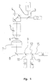
- Fig. 1 shows a schematic representation of a first embodiment of a microscope construction according to the invention.
- the microscope setup is a confocal laser scanning microscope.
- the microscope has one as a laser trained light source 1.
- the light source 1 emits an illuminating light beam 2, which is reflected via a main beam splitter 3 to a scanning device 4.
- the scanning device 4 guides the illuminating light beam 2 through microscope optics or a lens 5 through an object 6.
- Both that passing through the object 6 Transmission light as well as the fluorescent light generated in object 6 reaches a first via a condenser 7 and a deflecting mirror 8
- Color beam splitter 9 the spectrally lower-wave region 10 of the fluorescent light split off and reflected to a fluorescent light detector 11.
- About one Color beam splitter 12 becomes the spectrally higher-wave region 13 of the fluorescent light reflected to another fluorescent light detector 14.
- the transmission light 15 arrives at a transmission light detector arranged in a straight direction 16.
- the microscope structure accordingly assigns a light source 1 for illuminating one examining object 6 and two fluorescent light detectors 11 and 14 for detection of fluorescent light 10 and 13 generated in the object 6 and a transmission light detector 16 for the detection of transmission light passing through the object 6 15 on.
- the fluorescent light and transmission light detectors 11, 14 and 16 arranged such that a simultaneous detection of fluorescence and transmission light 10, 13 and 15 is made possible.
- the microscope structure shown in FIG. 1 also has a detector 17, which is arranged on the lens side.
- Both fluorescent light detectors 11 and 14 are on the side facing away from the light source 1 Side of the object 6 arranged. Furthermore, the transmission light detector 16 is arranged on the side of the object 6 facing away from the light source 1.
- Fig. 2 shows a schematic representation of a second embodiment of a microscope construction according to the invention.
- the microscope structure shown in Fig. 2 corresponds essentially to the microscope structure from FIG. 1, components, correspond to the components already described in FIG. 1, with the same Reference numbers are designated.
- the microscope structure shown in FIG. 2 is in particular for differential interference contrasting - DIC - suitable for simultaneous fluorescence detection.
- the microscope structure has two polarization devices designed as polarization prisms 18 on.
- the polarization prisms 18 are so-called Wollaston prisms educated.
- One polarization prism 18 is between the light source 1 and the object 6, more precisely in front of the lens 5.
- the second polarization prism 18 is arranged after the object 6, more precisely after the condenser 7.
- phase objects can be simultaneously Fluorescence detection can be observed.
- the linearly polarized excitation light the light source 1 designed as a laser is in front of the lens 5 with the aid of first polarization prism 18 split into two partial beams. Subsequently the two partial beams pass through object 6 in slightly different ways, to unite after the condenser 7 with the help of the second polarization prism 18 become. If the two partial beams have different optical path lengths covered, this manifests itself in a rotation of the beam union Linear polarization level, which with the help of a polarization filter 19 before Transmission light detector 16 is analyzed.
- the polarization filter 19 must be so oriented that it passes directly through without polarization prisms 18 would block the illuminating beam.
- FIG. 3 shows a schematic representation of a third embodiment of a microscope construction according to the invention.
- the microscope setup shown here corresponds essentially the microscope structure shown in FIG. 1, components, correspond to the components already described in FIG. 1, with the same Reference numbers are designated.
- the microscope structure shown in FIG. 3 can be used in particular for phase contrasting be used.
- the microscope structure has one in the Fourier plane segment aperture 20 arranged in front of the transmission light detector 16. Fluorescent light 10 and 13 can be observed simultaneously.
- the Dodt method can be carried out with the segment aperture 20.
- a segment polarization optics can also be used, with the.
- the Hoffman method can be carried out, the fluorescent light 10 and 13 is observable. In the case of single-photon excitation, the fluorescent light is 10 and 13 but not observable confocally.
- FIG. 4 shows a fourth exemplary embodiment of a microscope construction according to the invention.
- the microscope structure shown in Fig. 4 largely corresponds to the microscope structure shown in FIG. 1, components, correspond to the components already described in FIG. 1, with the same Reference numbers are designated.
- the object 6 is by means of an additional light source 21 also illuminated on the condenser side.
- the additional light source 21 is thus arranged on the side of the object 6 facing away from the light source 1. It is here an additional reverse beam path.
- the additional light source 21 is a segment diaphragm 20 in for phase contrasting assigned to the Fourier plane in front of the additional light source 21.
- the additional light source 21 generates an illuminating light beam 22 which extends through the sample 6 and is detected by means of the detector 17.
- the illuminating light beam is experienced before detection 22 a scanning process by means of the scanning device 4.
- the transmission light detector 17 could also be referred to as a scanner detector. By this scanner detector 17, for example, the Dodt or Hoffman light can be detected.
- the microscope structure according to the invention could be used especially for two-photon excitation can be used because here a differentiation of fluorescence photons from the focus region of fluorescence photons from the neighboring regions an aperture arrangement is unnecessary. Furthermore, the microscope setup is also available for interference contrast microscopy with the help of polarization prisms and Transmitted light contrast microscopy with the aid of segment diaphragms.
- the microscope setup can be used for the sequential detection of different fluorescence spectral ranges and / or of transmission light without mechanical switching processes be used.
- the microscope structure is particularly suitable for applications with micropipettes, micromanipulators or similar.
Abstract
Ein Mikroskop-Aufbau, insbesondere für die konfokale Scan-Mikroskopie, mit einer Lichtquelle (1) zur Beleuchtung eines zu untersuchenden Objekts (6) und mindestens einem Fluoreszenzlicht-Detektor (11, 14) zur Detektion von in dem Objekt (6) erzeugtem Fluoreszenzlicht (10, 13) und mindestens einem Transmissionslicht-Detektor (16) zur Detektion von durch das Objekt (6) tretendem Transmissionslicht (15) ist im Hinblick auf eine sichere Durchführung unterschiedlichster Experimente mit jeweils hohem Detektionsgrad derart ausgestaltet und weitergebildet, dass die Fluoreszenzlicht- und Transmissionslicht-Detektoren (11, 14; 16) derart angeordnet sind, dass eine simultane Detektion von Fluoreszenz- und Transmissionslicht (10, 13; 15) ermöglicht ist. <IMAGE>A microscope assembly, in particular for confocal scanning microscopy, with a light source (1) for illuminating an object (6) to be examined and at least one fluorescent light detector (11, 14) for detecting fluorescent light generated in the object (6) (10, 13) and at least one transmission light detector (16) for the detection of transmission light (15) passing through the object (6) is designed and developed with a view to reliably carrying out a wide variety of experiments, each with a high degree of detection, such that the fluorescent light and transmission light detectors (11, 14; 16) are arranged such that simultaneous detection of fluorescent and transmission light (10, 13; 15) is made possible. <IMAGE>
Description
Die Erfindung betrifft einen Mikroskop-Aufbau, insbesondere für die konfokale Scan-Mikroskopie, mit einer Lichtquelle zur Beleuchtung eines zu untersuchenden Objekts und mindestens einem Fluoreszenzlicht-Detektor zur Detektion von in dem Objekt erzeugtem Fluoreszenzlicht und mindestens einem Transmissionslicht-Detektor zur Detektion von durch das Objekt tretendem Transmissionslicht.The invention relates to a microscope structure, in particular for confocal scanning microscopy, with a light source for illuminating an object to be examined and at least one fluorescent light detector for detecting in the object generated fluorescent light and at least one transmission light detector for Detection of transmission light passing through the object.
Mikroskop-Aufbauten der eingangs genannten Art sind aus der Praxis bekannt und existieren in den unterschiedlichsten Ausführungsformen. Ein Beispiel eines derartigen Mikroskop-Aufbaus wird durch ein konfokales Scan-Mikroskop gebildet, bei dem ein zu untersuchendes Objekt mit einem Lichtstrahl abgerastert wird. Das Mikroskop umfasst im allgemeinen eine Lichtquelle und eine Fokussieroptik, mit der das Licht der Quelle auf eine Lochblende fokussiert wird. Dabei sind ein Strahlteiler, eine Scaneinrichtung zur Strahlsteuerung, eine Mikroskopoptik, eine Detektionsblende und Detektoren zum Nachweis von Detektions- bzw. Fluoreszenzlicht vorgesehen.Microscope assemblies of the type mentioned are known from practice and exist in a wide variety of embodiments. An example of one Microscope assembly is formed by a confocal scanning microscope, in which an object to be examined is scanned with a light beam. The microscope generally comprises a light source and focusing optics with which the light the source is focused on a pinhole. There are one beam splitter, one Scanning device for beam control, microscope optics, a detection aperture and detectors for detecting detection or fluorescent light.
Das Beleuchtungslicht wird meist über den Strahlteiler eingekoppelt. Der Fokus des Lichtstrahls wird mit der Scaneinrichtung in einer Probenebene bewegt. Hierzu sind üblicherweise zwei Spiegel verwendet, die verkippt werden, wobei die Ablenkachsen meist senkrecht aufeinanderstehen, so dass ein Spiegel in X- und der andere in Y-Richtung ablenkt. Die Verkippung der Spiegel wird bspw. mit Hilfe von Galvanometer-Stellelementen bewerkstelligt. Das von der Probe kommende Fluoreszenz- oder Reflexionslicht gelangt in dieser meist üblichen Descan-Anordnung über dieselben Scanspiegel zurück zum Strahlteiler und passiert diesen, um anschließend auf die Detektionsblende fokussiert zu werden, hinter der sich die Detektoren befinden. Detektionslicht, das nicht direkt aus der Fokusregion stammt, nimmt einen anderen Lichtweg und passiert die Detektionsblende nicht, so dass man eine Punktinformation erhält, die durch Abrastern des Objekts zu einem dreidimensionalen Bild führt. Beleuchtung und Detektion finden hierbei objektivseitig, d. h. auf Seiten der Mikroskopoptik statt.The illuminating light is usually coupled in via the beam splitter. The focus of the The light beam is moved in a sample plane with the scanning device. For this are Usually two mirrors are used, which are tilted, the deflection axes usually stand perpendicular to each other, so that one mirror in the X and the other in the Y direction distracts. The mirror is tilted, for example, with the help of galvanometer actuators accomplished. The fluorescence or In this mostly common descan arrangement, reflection light passes through the same Scan mirror back to the beam splitter and passes this, then to the Detection aperture to be focused behind which the detectors are located. Detection light, that does not come directly from the focus region takes another Light path and does not pass the detection aperture, so you get a point information obtained, which leads to a three-dimensional image by scanning the object. Illumination and detection take place on the lens side, d. H. on the part of microscope optics instead of.
Es ist auch möglich, in einer Durchlichtanordnung bspw. das Fluoreszenzlicht oder das Transmissionslicht - die Transmission des Anregungslichts - kondensorseitig, d.h. auf der Seite eines nach dem Objekt angeordneten Kondensors, zu detektieren. Der Detektionslichtstrahl gelangt dann nicht über die Scanspiegel zum Detektor. Eine derartige Anordnung wird als Non-Descan-Anordnung bezeichnet. It is also possible, for example, to transmit the fluorescent light or the transmission light - the transmission of the excitation light - on the condenser side, i.e. on the side of a condenser arranged after the object. The detection light beam then does not reach the detector via the scanning mirror. A such an arrangement is referred to as a non-descan arrangement.
Für die Detektion des Fluoreszenzlichts wäre in der Durchlichtanordnung eine kondensorseitige Detektionsblende nötig, um - wie in der beschriebenen Descan-Anordnung - eine dreidimensionale Auflösung zu erreichen. Im Fall der Zweiphotonenanregung kann jedoch auf eine kondensorseitige Detektionsblende verzichtet werden, da die Anregungswahrscheinlichkeit vom Quadrat der Photonendichte bzw. der Intensität abhängt, die naturgemäß im Fokus viel höher ist als in den Nachbarregionen. Das zu detektierende Fluoreszenzlicht stammt daher mit großer Wahrscheinlichkeit zum allergrößten Teil aus der Fokusregion, was eine weitere Differenzierung von Fluoreszenzphotonen aus der Fokusregion von Fluoreszenzphotonen aus den Nachbarregionen mit einer Blendenanordnung überflüssig macht.For the detection of the fluorescent light there would be a condenser side in the transmitted light arrangement Detection aperture necessary to - as in the described descan arrangement - to achieve a three-dimensional resolution. In the case of two-photon excitation However, a condenser-side detection diaphragm can be dispensed with because the excitation probability from the square of the photon density or the intensity depends, which is naturally much higher in focus than in the neighboring regions. The The fluorescent light to be detected is therefore very likely to be most of it from the focus region, which is a further differentiation of fluorescence photons from the focus region of fluorescence photons from the neighboring regions with an aperture arrangement.
Insbesondere vor dem Hintergrund einer ohnehin geringen Ausbeute an Fluoreszenzphotonen bei der Zweiphotonenanregung ist eine Non-Descan-Anordnung, bei der im allgemeinen auf dem Detektionslichtweg weniger Licht verloren geht, interessant. Dennoch sind auch bei dieser Art der Beobachtung von Fluoreszenzlicht bspw. Zellumrisse aufgrund der Nichtmarkierung in lebenden Präparaten nicht ausreichend gut detektierbar, so dass man sich wünschen würde, gleichzeitig das Transmissionslicht beobachten zu können, das klare Rückschlüsse zuließe.Especially against the background of an already low yield of fluorescence photons with the two-photon excitation is a non-descan arrangement, with that generally less light is lost in the detection light path, interesting. Nevertheless, with this type of observation of fluorescent light, for example. Cell outline insufficient due to non-labeling in live specimens well detectable, so that one would wish for the transmission light at the same time to be able to observe that would allow clear conclusions to be drawn.
Es gibt nun Mikroskop-Aufbauten, bei denen einerseits eine objektivseitige Fluoreszenzdetektion und andererseits eine kondensorseitige Transmissionsdetektion möglich ist. Zum Wechsel von der objektivseitigen Fluoreszenzdetektion auf die kondensorseitige Transmissionsdetektion und umgekehrt ist hierbei jedoch ein mechanischer Umschaltvorgang erforderlich, bei dem Spiegel und Filter mechanisch verschoben werden müssen. Dabei können Erschütterungen des Objekts auftreten, die das Objekt zerstören. Insbesondere Experimente mit Mikropipetten-Anordnungen sind somit fast ausgeschlossen.There are now microscope assemblies in which on the one hand objective-side fluorescence detection and on the other hand condenser-side transmission detection is possible is. For switching from the fluorescence detection on the lens side to the condenser side However, transmission detection and vice versa is a mechanical one Switching process required where the mirror and filter are mechanically shifted Need to become. This can cause shocks to the object destroy the object. Especially experiments with micropipette arrangements are almost impossible.
Der vorliegenden Erfindung liegt daher die Aufgabe zugrunde, einen Mikroskop-Aufbau der eingangs genannten Art anzugeben, bei dem unterschiedlichste Experimente, insbesondere Experimente mit Mikropipetten-Anordnungen, mit jeweils hohem Detektionsgrad sicher möglich sind. The present invention is therefore based on the object of a microscope construction of the type mentioned at the beginning, in which a wide variety of experiments, especially experiments with micropipette arrangements, each with high Degree of detection are certainly possible.
Die voranstehende Aufgabe wird durch einen Mikroskop-Aufbau mit den Merkmalen
des Patentanspruchs 1 gelöst. Danach ist der Mikroskop-Aufbau derart ausgestaltet,
dass die Fluoreszenzlicht- und Transmissionslicht-Detektoren derart angeordnet
sind, dass eine simultane Detektion von Fluoreszenz- und Transmissionslicht ermöglicht
ist.The above task is accomplished by a microscope setup with the features
of
In erfindungsgemäßer Weise ist erkannt worden, dass durch geschickte Anordnung der Fluoreszenzlicht- und Transmissionslicht-Detektoren die obige Aufgabe auf überraschend einfache Weise gelöst ist. Hierzu sind die Fluoreszenzlicht- und Transmissionslicht-Detektoren derart anzuordnen, dass eine simultane Detektion von Fluoreszenzlicht und Transmissionslicht ermöglicht ist. Ein Umschalten zwischen der Transmissionslicht- und Fluoreszenzlicht-Detektion ist dabei nicht mehr erforderlich, so dass mechanische Erschütterungen der Probe bzw. des Objekts vermieden sind. Somit ist ein hoher Detektionsgrad sowohl hinsichtlich der Detektion von Transmissionslicht als auch hinsichtlich der Detektion von Fluoreszenzlicht auch bei empfindlichen Objekten realisiert.In the manner according to the invention it has been recognized that by clever arrangement of the fluorescent light and transmission light detectors surprisingly did the above task is easily solved. The fluorescence light and transmission light detectors are for this purpose to be arranged such that a simultaneous detection of fluorescent light and transmission light is enabled. Switching between the Transmission light and fluorescent light detection is no longer required, so that mechanical vibrations of the sample or the object are avoided. A high degree of detection is thus both with regard to the detection of transmission light as well as with regard to the detection of fluorescent light even with sensitive Objects realized.
Folglich ist mit dem erfindungsgemäßen Mikroskop-Aufbau ein Mikroskop-Aufbau angegeben, bei dem unterschiedlichste Experimente, insbesondere Experimente mit Mikropipetten-Anordnungen, mit jeweils hohem Detektionsgrad sicher möglich sind.Consequently, the microscope structure according to the invention is a microscope structure specified, in which a wide variety of experiments, especially experiments with Micropipette arrangements, each with a high degree of detection, are reliably possible.
In einer konkreten Ausführungsform könnte mindestens ein Fluoreszenzlicht-Detektor auf der der Lichtquelle abgewandten Seite des Objekts angeordnet sein. Alternativ oder zusätzlich hierzu könnte mindestens ein Transmissionslicht-Detektor auf der der Lichtquelle abgewandten Seite des Objekts angeordnet sein. Dadurch ist bspw. eine simultane Detektion von Fluoreszenz- und Transmissionslicht mittels Detektoren möglich, die jeweils auf der der Lichtquelle abgewandten Seite des Objekts angeordnet sind. Dies hat den Vorteil einer übersichtlichen Anordnung der Detektoren in einem bestimmten Bereich des Mikroskop-Aufbaus.In a specific embodiment, at least one fluorescent light detector could be used be arranged on the side of the object facing away from the light source. Alternatively or in addition to this, at least one transmission light detector could be on the the side of the object facing away from the light source. For example, simultaneous detection of fluorescence and transmission light by means of detectors possible, each arranged on the side of the object facing away from the light source are. This has the advantage of a clear arrangement of the detectors in one specific area of the microscope assembly.
Des weiteren könnte auf der der Lichtquelle abgewandten Seite des Objekts ein Kondensor für das Transmissionslicht und das Fluoreszenzlicht angeordnet sein. Im Hinblick auf eine besonders effektive Lichtsammlung könnte die Apertur des Kondensors größer als die Apertur eines zwischen der Lichtquelle und dem Objekt angeordneten Objektiv sein. Bei Vorliegen eines derartigen Kondensors kann bei entsprechender Anordnung der Detektoren von einer kondensorseitigen Detektion von Fluoreszenzlicht und Transmissionslicht gesprochen werden.Furthermore, one could on the side of the object facing away from the light source Condenser for the transmission light and the fluorescent light can be arranged. in the The aperture of the condenser could be used for a particularly effective light collection larger than the aperture of one arranged between the light source and the object Be objective. In the presence of such a condenser, the corresponding Arrangement of the detectors from a condenser-side detection of Fluorescent light and transmission light can be spoken.
Zur separaten Detektion von Transmissionslicht und Fluoreszenzlicht könnten das Transmissionslicht und das Fluoreszenzlicht auf der der Lichtquelle abgewandten Seite des Objekts, vorzugsweise nach Durchgang durch den Kondensor, aufspaltbar sein. Hierdurch wäre eine räumliche Trennung des Fluoreszenzlichts vom Transmissionslicht erreicht. Dies ermöglicht die separate Messung der entsprechenden Lichtleistungen in verschiedenen Detektoren.For the separate detection of transmission light and fluorescent light, this could Transmission light and the fluorescent light on that facing away from the light source Side of the object, preferably after passing through the condenser, can be split his. This would be a spatial separation of the fluorescent light from the transmission light reached. This enables the corresponding light outputs to be measured separately in different detectors.
Im konkreten könnte zur Aufspaltung mindestens ein Farbstrahlteiler eingesetzt sein. Dabei könnten mehrere Farbstrahlteiler hintereinander angeordnet sein, um eine Abspaltung unterschiedlicher Wellenlängen oder Wellenlängenbereiche zu ermöglichen.Specifically, at least one color beam splitter could be used for the splitting. Several color beam splitters could be arranged one behind the other in order to separate them to enable different wavelengths or wavelength ranges.
Alternativ hierzu könnte zur Aufspaltung mindestens ein teildurchlässiger Spiegel eingesetzt sein. Diesem Spiegel oder diesen Spiegeln könnte ein Band- oder Blockfilter nachgeordnet sein. Auch bei der Verwendung von Spiegeln als Aufspaltungsbauteil könnten mehrere derartige Spiegel hintereinander, ggf. mit einem nachgeordneten Band- oder Blockfilter, angeordnet sein. Auch hierdurch ist eine Aufspaltung des Fluoreszenzlichts in mehrere Spektralbereiche möglich.Alternatively, at least one partially transparent mirror could be used for the splitting be used. This mirror or mirrors could be a band or block filter be subordinate. Even when using mirrors as a splitting component could several such mirrors in a row, possibly with a subordinate Band or block filters. This also causes a split of the fluorescent light possible in several spectral ranges.
Alternativ zur Verwendung von Farbstrahlteilern oder Spiegeln könnte zur Aufspaltung ein Multibanddetektor eingesetzt werden, der bspw. in der DE 199 02 625 A1 beschrieben ist. Mit einem derartigen Multibanddetektor ist ebenfalls eine Aufspaltung des Fluoreszenzlichts in mehrere Spektralbereiche möglich.An alternative to using color beam splitters or mirrors could be to split a multiband detector can be used, for example in DE 199 02 625 A1 is described. With such a multiband detector, splitting is also possible of the fluorescent light possible in several spectral ranges.
Das Fluoreszenzlicht und das Transmissionslicht könnten bei einer besonders kompakten Ausgestaltung des Mikroskops im selben Detektor detektierbar sein. Im Hinblick auf eine möglichst klare Differenzierung könnten das Fluoreszenzlicht und das Transmissionslicht jedoch in verschiedenen Detektoren detektierbar sein.The fluorescent light and the transmission light could be particularly compact Design of the microscope to be detectable in the same detector. With regard the fluorescence light and the However, transmission light can be detectable in different detectors.
Der erfindungemäße Mikroskop-Aufbau kann insbesondere zur Interferenzkontrast-Mikroskopie verwendet werden. Hierzu könnte zwischen der Lichtquelle und dem Objekt, vorzugsweise vor dem Objektiv, eine erste Polarisationseinrichtung und nach dem Objekt, vorzugsweise nach dem Kondensor, eine zweite Polarisationseinrichtung angeordnet sein. Eine derartige Polarisationseinrichtung könnte auch eine Polarisationsaufspaltungseinrichtung sein, die beispielsweise bereits polarisiertes Licht in senkrecht zueinander polarisierte Komponenten aufspalten könnte. Die Polarisationseinrichtungen könnten in besonders einfacher Weise durch Prismen gebildet sein. Hierbei bieten sich insbesondere Wollaston-Prismen an.The microscope structure according to the invention can be used in particular for interference contrast microscopy be used. This could be between the light source and the Object, preferably in front of the lens, a first polarization device and after the object, preferably after the condenser, a second polarization device be arranged. Such a polarization device could also be a Polarization splitting device that is already polarized, for example Could split light into polarized components perpendicular to each other. The Polarization devices could be used in a particularly simple manner through prisms be educated. Wollaston prisms are particularly suitable here.
Zur Feststellung, ob eine Drehung der Linearpolarisationsebene stattgefunden hat, könnte vor dem Transmissionslicht-Detektor ein Polarisationsfilter angeordnet sein. Der Polarisationsfilter muss dabei so orientiert sein, dass er einen Beleuchtungslichtstrahl ohne Beeinflussung mittels einer Polarisationseinrichtung blockieren würde.To determine whether the linear polarization plane has rotated, a polarization filter could be arranged in front of the transmission light detector. The polarization filter must be oriented so that it has an illuminating light beam would block without interference by means of a polarization device.
Der erfindungsgemäße Mikroskop-Aufbau könnte auch bei der DurchlichtkontrastMikroskopie eingesetzt werden. Hierzu könnte im Strahlengang eine Segmentoptik, Segmentpolarisationsoptik, Segmentblende, Segmentphasenblende oder ein Segmentphasenfilter angeordnet sein. Dabei könnte die Segmentoptik, Segmentpolarisationsoptik, Segmentblende, Segmentphasenblende oder der Segmentphasenfilter in einer Fourier-Ebene des Strahlengangs angeordnet sein. Hierzu könnte die Segmentoptik, Segmentpolarisationsoptik, Segmentblende, Segmentphasenblende oder der Segmentphasenfilter in der Fourier-Ebene unmittelbar vor dem Transmissionslicht-Detektor angeordnet sein. Hierdurch ließe sich bspw. das Dodt-Verfahren oder das Hoffman-Verfahren realisieren. Dabei könnte simultan auch das Fluoreszenzlicht beobachtet werden, wobei dies bei einer Einphotonenanregung nicht konfokal erfolgen kann.The microscope structure according to the invention could also be used in transmitted light contrast microscopy be used. For this purpose, segment optics in the beam path, Segment polarization optics, segment aperture, segment phase aperture or a segment phase filter be arranged. The segment optics, segment polarization optics, Segment aperture, segment phase aperture or the segment phase filter be arranged in a Fourier plane of the beam path. The segment optics, Segment polarization optics, segment aperture, segment phase aperture or the segment phase filter in the Fourier plane immediately in front of the transmission light detector be arranged. This could be, for example, the Dodt process or implement the Hoffman process. The fluorescent light could also be used simultaneously are observed, but this is not confocal with single-photon excitation can.
Hinsichtlich einer weiteren besonderen Ausgestaltung des Mikroskop-Aufbaus könnte eine Zusatz-Lichtquelle auf der der Lichtquelle abgewandten Seite des Objekts - bei Vorhandensein eines Kondensors kondensorseitig - angeordnet sein. Hierdurch könnte das Objekt ggf. kondensorseitig beleuchtet werden, wobei eine Detektion dann auf der der Lichtquelle zugewandten Seite des Objekts - objektivseitig - erfolgen könnte. Die Zusatz-Lichtquelle könnte in einfacher Weise eine Weißlichtquelle sein.With regard to a further special configuration of the microscope structure could be an additional light source on the side of the object facing away from the light source - In the presence of a condenser - be arranged on the condenser side. In this way, the object could possibly be illuminated on the condenser side, with one Detection then on the side of the object facing the light source - on the lens side - could be done. The additional light source could easily be a white light source his.
Zur Phasenkontrastierung könnte der Zusatz-Lichtquelle eine Segmentoptik, Segmentpolarisationsoptik, Segmentblende, Segmentphasenblende oder ein Segmentphasenfilter zugeordnet sein. In besonders günstiger Weise könnte die Segmentoptik, Segmentpolarisationsoptik, Segmentblende, Segmentphasenblende oder der Segmentphasenfilter in der Fourier-Ebene vor der Zusatz-Lichtquelle angeordnet sein.For phase contrasting, the additional light source could be segment optics, segment polarization optics, Segment aperture, segment phase aperture or a segment phase filter be assigned. The segment optics, Segment polarization optics, segment aperture, segment phase aperture or the Segment phase filter arranged in the Fourier plane in front of the additional light source his.
Auf der der Lichtquelle zugewandten Seite des Objekts könnte eine Scaneinrichtung angeordnet sein. Das von der Zusatz-Lichtquelle erzeugte Licht könnte ebenfalls von der Scaneinrichtung abgelenkt werden, bevor es auf einen Transmissionslicht-Detektor oder Scannerdetektor trifft. Hierzu könnte auf der der Lichtquelle zugewandten Seite des Objekts, vorzugsweise auf der dem Objekt abgewandten Seite der Scaneinrichtung, mindestens ein Transmissionslicht-Detektor angeordnet sein.A scanning device could be located on the side of the object facing the light source be arranged. The light generated by the additional light source could also be from the scanning device be deflected before it is transmitted to a transmission light detector or scanner detector hits. This could be done by facing the light source Side of the object, preferably on the side of the object facing away from the object Scanning device, at least one transmission light detector can be arranged.
Als Lichtquelle könnte in besonders vorteilhafter Weise ein Laser verwendet sein. Es ist jedoch auch die Verwendung anderer geeigneter Lichtquellen denkbar.A laser could be used in a particularly advantageous manner as the light source. It however, the use of other suitable light sources is also conceivable.
Der erfindungsgemäße Mikroskop-Aufbau ist insbesondere zur simultanen Detektion eines oder mehrerer Wellenlängenbereiche des durch Mehrphotonenanregung erzeugten Fluoreszenzlichts und/oder des durch Einphotonenanregung, SHG - Second Harmonic Generation -, erzeugten Fluoreszenzlichts und des Transmissionslichts geeignet.The microscope structure according to the invention is in particular for simultaneous detection one or more wavelength ranges of that generated by multi-photon excitation Fluorescent light and / or by single-photon excitation, SHG - Second Harmonic Generation -, generated fluorescent light and transmission light suitable.
Bei einer speziellen Anwendung könnte der erfindungsgemäße Mikroskop-Aufbau auch dazu verwendet werden, Fluoreszenzlicht verschiedener Wellenlängenbereiche und Transmissionslicht sequentiell und nicht simultan zu detektieren, ohne dass mechanische Umschaltvorgänge, bspw. Verschiebung oder Austausch von Strahlteilern oder Filtern, erforderlich sind, die zwangsläufig Erschütterungen der Probe verursachen. Der Mikroskop-Aufbau ist daher insbesondere auch zur sequentiellen Detektion verschiedener Fluoreszenzspektralbereiche und/oder von Transmissionslicht bei Anwendungen mit Objekten geeignet, die von außen bspw. durch Mikromanipulatoren, Mikropipetten oder ähnlichem beeinflusst werden.The microscope structure according to the invention could be used for a special application also used fluorescent light of different wavelength ranges and to detect transmission light sequentially and not simultaneously without mechanical Switching processes, e.g. shifting or replacement of beam splitters or filtering, which inevitably cause vibration of the sample. The microscope setup is therefore particularly suitable for sequential detection different fluorescence spectral ranges and / or transmission light Suitable for applications with objects that are externally, for example, using micromanipulators, Micropipettes or the like can be influenced.
Es gibt nun verschiedene Möglichkeiten, die Lehre der vorliegenden Erfindung in vorteilhafter Weise auszugestalten und weiterzubilden. Dazu ist einerseits auf die dem Patentanspruch 1 nachgeordneten Ansprüche, andererseits auf die nachfolgende Erläuterung mehrerer Ausführungsbeispiele der Erfindung anhand der Zeichnung zu verweisen. In Verbindung mit der Erläuterung der bevorzugten Ausführungsbeispiele der Erfindung anhand der Zeichnung werden auch im allgemeinen bevorzugte Ausgestaltungen und Weiterbildungen der Lehre erläutert. In der Zeichnung zeigen
- Fig. 1
- in einer schematischen Darstellung ein erstes Ausführungsbeispiel eines erfindungsgemäßen Mikroskop-Aufbaus,
- Fig. 2
- in einer schematischen Darstellung ein zweites Ausführungsbeispiel eines erfindungsgemäßen Mikroskop-Aufbaus mit zwei Polarisationsprismen,
- Fig. 3
- in einer schematischen Darstellung ein drittes Ausführungsbeispiel eines erfindungsgemäßen Mikroskop-Aufbaus mit einer Segmentblende und
- Fig. 4
- in einer schematischen Darstellung ein viertes Ausführungsbeispiel eines erfindungsgemäßen Mikroskop-Aufbaus mit einer Zusatz-Lichtquelle.
- Fig. 1
- a schematic representation of a first embodiment of a microscope structure according to the invention,
- Fig. 2
- a schematic representation of a second embodiment of a microscope structure according to the invention with two polarization prisms,
- Fig. 3
- in a schematic representation, a third embodiment of a microscope structure according to the invention with a segment aperture and
- Fig. 4
- a fourth embodiment of a microscope assembly according to the invention with an additional light source in a schematic representation.
Fig. 1 zeigt in einer schematischen Darstellung ein erstes Ausführungsbeispiel eines
erfindungsgemäßen Mikroskop-Aufbaus. Bei dem Mikroskop-Aufbau handelt es sich
um ein konfokales Laser-Scanning-Mikroskop. Das Mikroskop weist eine als Laser
ausgebildete Lichtquelle 1 auf. Die Lichtquelle 1 emittiert einen Beleuchtungslichtstrahl
2, der über einen Hauptstrahlteiler 3 zu einer Scaneinrichtung 4 reflektiert wird.
Die Scaneinrichtung 4 führt den Beleuchtungslichtstrahl 2 durch eine Mikroskopoptik
bzw. ein Objektiv 5 hindurch über ein Objekt 6. Sowohl das durch das Objekt 6 hindurchtretende
Transmissionslicht als auch das im Objekt 6 erzeugte Fluoreszenzlicht
gelangt über einen Kondensor 7 und einen Umlenkspiegel 8 zu einem ersten
Farbstrahlteiler 9, der den spektral niedrigerwelligen Bereich 10 des Fluoreszenzlichts
abspaltet und zu einem Fluoreszenzlicht-Detektor 11 reflektiert. Über einen
Farbstrahlteiler 12 wird der spektral höherwellige Bereich 13 des Fluoreszenzlichts
zu einem weiteren Fluoreszenzlicht-Detektor 14 reflektiert. Das Transmissionslicht 15
gelangt zu einem in Geradeausrichtung angeordneten Transmissionslicht-Detektor
16. Fig. 1 shows a schematic representation of a first embodiment of a
microscope construction according to the invention. The microscope setup is
a confocal laser scanning microscope. The microscope has one as a laser
trained
Der Mikroskop-Aufbau weist demnach eine Lichtquelle 1 zur Beleuchtung eines zu
untersuchenden Objekts 6 und zwei Fluoreszenzlicht-Detektoren 11 und 14 zur Detektion
von in dem Objekt 6 erzeugtem Fluoreszenzlicht 10 und 13 und einen Transmissionslicht-Detektor
16 zur Detektion von durch das Objekt 6 tretendem Transmissionslicht
15 auf. Dabei sind die Fluoreszenzlicht- und Transmissionslicht-Detektoren
11, 14 und 16 derart angeordnet, dass eine simultane Detektion von Fluoreszenz-
und Transmissionslicht 10, 13 und 15 ermöglicht ist.The microscope structure accordingly assigns a
Der in Fig. 1 gezeigte Mikroskop-Aufbau weist des weiteren einen Detektor 17 auf,
der objektivseitig angeordnet ist.The microscope structure shown in FIG. 1 also has a
Beide Fluoreszenzlicht-Detektoren 11 und 14 sind auf der der Lichtquelle 1 abgewandten
Seite des Objekts 6 angeordnet. Des weiteren ist der Transmissionslicht-Detektor
16 auf der der Lichtquelle 1 abgewandten Seite des Objekts 6 angeordnet.Both fluorescent
Fig. 2 zeigt in einer schematischen Darstellung ein zweites Ausführungsbeispiel eines erfindungsgemäßen Mikroskop-Aufbaus. Der in Fig. 2 gezeigte Mikroskop-Aufbau entspricht im wesentlichen dem Mikroskop-Aufbau aus Fig. 1, wobei Bauelemente, die bereits in Fig. 1 beschriebenen Bauelementen entsprechen, mit denselben Bezugsziffern bezeichnet sind.Fig. 2 shows a schematic representation of a second embodiment of a microscope construction according to the invention. The microscope structure shown in Fig. 2 corresponds essentially to the microscope structure from FIG. 1, components, correspond to the components already described in FIG. 1, with the same Reference numbers are designated.
Der in Fig. 2 gezeigte Mikroskop-Aufbau ist insbesondere zur differentiellen Interferenzkontrastierung
- DIC - bei simultaner Fluoreszenzdetektion geeignet. Hierzu
weist der Mikroskop-Aufbau zwei als Polarisationsprismen 18 ausgebildete Polarisationseinrichtungen
auf. Die Polarisationsprismen 18 sind durch sog. Wollaston-Prismen
gebildet. Das eine Polarisationsprisma 18 ist zwischen der Lichtquelle 1 und
dem Objekt 6, genauer gesagt vor dem Objektiv 5, angeordnet. Das zweite Polarisationsprisma
18 ist nach dem Objekt 6, genauergesagt nach dem Kondensor 7, angeordnet.The microscope structure shown in FIG. 2 is in particular for differential interference contrasting
- DIC - suitable for simultaneous fluorescence detection. For this
the microscope structure has two polarization devices designed as
Mittels der differentiellen Interferenzkontrastierung können Phasenobjekte bei gleichzeitiger
Fluoreszenzdetektion beobachtet werden. Das linear polarisierte Anregungslicht
der als Laser ausgebildeten Lichtquelle 1 wird vor dem Objektiv 5 mit Hilfe des
ersten Polarisationsprismas 18 in zwei Teilstrahlen aufgespalten. Anschliessend
durchlaufen die beiden Teilstrahlen das Objekt 6 auf leicht verschiedenen Wegen,
um nach dem Kondensor 7 mit Hilfe des zweiten Polarisationsprismas 18 vereinigt zu
werden. Haben die beiden Teilstrahlen unterschiedlich lange optische Weglängen
zurückgelegt, so äussert sich dies nach der Strahlvereinigung in einer Drehung der
Linearpolarisationsebene, welche mit Hilfe eines Polarisationsfilters 19 vor dem
Transmissionslicht-Detektor 16 analysiert wird. Der Polarisationsfilter 19 muss dabei
so orientiert sein, dass er einen ohne Polarisationsprismen 18 direkt durchgehenden
Beleuchtungsstrahl blockieren würde.Using differential interference contrasting, phase objects can be simultaneously
Fluorescence detection can be observed. The linearly polarized excitation light
the
Fig. 3 zeigt in einer schematischen Darstellung ein drittes Ausführungsbeispiel eines erfindungsgemäßen Mikroskop-Aufbaus. Der hier gezeigte Mikroskop-Aufbau entspricht im wesentlichen dem in Fig. 1 gezeigten Mikroskop-Aufbau, wobei Bauelemente, die bereits in Fig. 1 beschriebenen Bauelementen entsprechen, mit denselben Bezugsziffern bezeichnet sind.Fig. 3 shows a schematic representation of a third embodiment of a microscope construction according to the invention. The microscope setup shown here corresponds essentially the microscope structure shown in FIG. 1, components, correspond to the components already described in FIG. 1, with the same Reference numbers are designated.
Der in Fig. 3 gezeigte Mikroskop-Aufbau kann insbesondere zur Phasenkontrastierung
verwendet werden. Hierzu weist der Mikroskop-Aufbau eine in der Fourier-Ebene
vor dem Transmissionslicht-Detektor 16 angeordnete Segmentblende 20 auf.
Dabei ist simultan Fluoreszenzlicht 10 und 13 beobachtbar.The microscope structure shown in FIG. 3 can be used in particular for phase contrasting
be used. For this purpose, the microscope structure has one in the Fourier
Mit der Segmentblende 20 ist das Dodt-Verfahren durchführbar. Alternativ zu einer
Segmentblende 20 ist auch eine Segmentpolarisationsoptik einsetzbar, mit der bspw.
das Hoffman-Verfahren durchführbar ist, wobei simultan das Fluoreszenzlicht 10 und
13 beobachtbar ist. Bei einer Einphotonenanregung ist das Fluoreszenzlicht 10 und
13 jedoch nicht konfokal beobachtbar.The Dodt method can be carried out with the
Fig. 4 zeigt in einer schematischen Darstellung ein viertes Ausführungsbeispiel eines erfindungsgemäßen Mikroskop-Aufbaus. Der in Fig. 4 gezeigte Mikroskop-Aufbau entspricht größtenteils dem in Fig. 1 gezeigten Mikroskop-Aufbau, wobei Bauelemente, die bereits in Fig. 1 beschriebenen Bauelementen entsprechen, mit denselben Bezugsziffern bezeichnet sind.4 shows a fourth exemplary embodiment of a microscope construction according to the invention. The microscope structure shown in Fig. 4 largely corresponds to the microscope structure shown in FIG. 1, components, correspond to the components already described in FIG. 1, with the same Reference numbers are designated.
Bei dem in Fig. 4 gezeigten Mikroskop-Aufbau ist das Objekt 6 mittels einer Zusatz-Lichtquelle
21 auch kondensorseitig beleuchtet. Die Zusatz-Lichtquelle 21 ist somit
auf der der Lichtquelle 1 abgewandten Seite des Objekts 6 angeordnet. Es liegt hierbei
also ein zusätzlicher umgekehrter Strahlverlauf vor.In the microscope construction shown in FIG. 4, the
Der Zusatz-Lichtquelle 21 ist zur Phasenkontrastierung eine Segmentblende 20 in
der Fourier-Ebene vor der Zusatz-Lichtquelle 21 zugeordnet. Die Zusatz-Lichtquelle
21 erzeugt einen Beleuchtungslichtstrahl 22, der durch die Probe 6 hindurch verläuft
und mittels des Detektors 17 detekiert wird. Vor der Detektion erfährt der Beleuchtungslichtstrahl
22 einen Scanvorgang mittels der Scaneinrichtung 4. Der Transmissionslicht-Detektor
17 könnte auch als Scanner-Detektor bezeichnet werden. Durch
diesen Scanner-Detektor 17 kann bspw. das Dodt- oder Hoffman-Licht erfasst werden.The additional
Der erfindungsgemäße Mikroskop-Aufbau könnte insbesondere bei der Zweiphotonenanregung verwendet werden, da hier eine Differenzierung von Fluoreszenzphotonen aus der Fokusregion von Fluoreszenzphotonen aus den Nachbarregionen mit einer Blendenanordnung überflüssig ist. Des weiteren bietet sich der Mikroskop-Aufbau zur Interferenzkontrast-Mikroskopie mit Hilfe von Polarisationsprismen und zur Durchlichtkontrastmikroskopie mit Hilfe von Segmentblenden an.The microscope structure according to the invention could be used especially for two-photon excitation can be used because here a differentiation of fluorescence photons from the focus region of fluorescence photons from the neighboring regions an aperture arrangement is unnecessary. Furthermore, the microscope setup is also available for interference contrast microscopy with the help of polarization prisms and Transmitted light contrast microscopy with the aid of segment diaphragms.
Der Mikroskop-Aufbau kann zur sequentiellen Detektion verschiedener Fluoreszenzspektralbereiche und/oder von Transmissionslicht ohne mechanische Umschaltvorgänge verwendet werden. Dabei ist der Mikroskop-Aufbau insbesondere für Anwendungen mit Mikropipetten, Mikromanipulatoren oder ähnlichem geeignet.The microscope setup can be used for the sequential detection of different fluorescence spectral ranges and / or of transmission light without mechanical switching processes be used. The microscope structure is particularly suitable for applications with micropipettes, micromanipulators or similar.
Hinsichtlich weiterer vorteilhafter Ausgestaltungen des erfindungsgemäßen Mikroskop-Aufbaus wird zur Vermeidung von Wiederholungen auf den allgemeinen Teil der Beschreibung sowie auf die beigefügten Patentansprüche verwiesen.With regard to further advantageous refinements of the microscope structure according to the invention is to avoid repetitions on the general part the description and reference to the appended claims.
Schließlich sei ausdrücklich darauf hingewiesen, dass die voranstehend beschriebenen Ausführungsbeispiele des erfindungsgemäßen Mikroskop-Aufbaus lediglich zur Erörterung der beanspruchten Lehre dienen, diese jedoch nicht auf diese Ausführungsbeispiele einschränken.Finally, it should be expressly pointed out that those described above Embodiments of the microscope structure according to the invention only for Discussion of the claimed teaching serve, but not on these embodiments restrict.
Claims (15)
Applications Claiming Priority (2)
| Application Number | Priority Date | Filing Date | Title |
|---|---|---|---|
| DE10003570A DE10003570A1 (en) | 2000-01-27 | 2000-01-27 | Microscope setup |
| DE10003570 | 2000-01-27 |
Publications (2)
| Publication Number | Publication Date |
|---|---|
| EP1128200A2 true EP1128200A2 (en) | 2001-08-29 |
| EP1128200A3 EP1128200A3 (en) | 2002-05-15 |
Family
ID=7628932
Family Applications (1)
| Application Number | Title | Priority Date | Filing Date |
|---|---|---|---|
| EP00123968A Ceased EP1128200A3 (en) | 2000-01-27 | 2000-11-03 | Microscope construction |
Country Status (4)
| Country | Link |
|---|---|
| US (1) | US6831780B2 (en) |
| EP (1) | EP1128200A3 (en) |
| JP (1) | JP5162781B2 (en) |
| DE (1) | DE10003570A1 (en) |
Cited By (2)
| Publication number | Priority date | Publication date | Assignee | Title |
|---|---|---|---|---|
| EP1617270A1 (en) * | 2004-07-16 | 2006-01-18 | CARL ZEISS JENA GmbH | Light scanning microscope with line-shaped illumination and use of the microscope |
| EP1617256A1 (en) * | 2004-07-16 | 2006-01-18 | CARL ZEISS JENA GmbH | Light scanning microscope with line-shaped illumination and use of the microscope |
Families Citing this family (21)
| Publication number | Priority date | Publication date | Assignee | Title |
|---|---|---|---|---|
| JP4804665B2 (en) * | 2001-08-09 | 2011-11-02 | オリンパス株式会社 | Laser microscope |
| US6888148B2 (en) * | 2001-12-10 | 2005-05-03 | Carl Zeiss Jena Gmbh | Arrangement for the optical capture of excited and /or back scattered light beam in a sample |
| DE10314750A1 (en) * | 2003-03-31 | 2004-11-04 | Leica Microsystems Heidelberg Gmbh | Scanning microscope for biological applications has an objective with a contrast device which enables use of the microscope in a Hoffman-modulation contrast mode |
| JP4647641B2 (en) * | 2003-04-14 | 2011-03-09 | ナノフォトン株式会社 | Laser microscope |
| DE10332064A1 (en) * | 2003-07-11 | 2005-01-27 | Carl Zeiss Jena Gmbh | Arrangement for detecting the illumination radiation in a laser scanning microscope |
| DE102004029733B4 (en) | 2003-07-26 | 2022-03-31 | Leica Microsystems Cms Gmbh | Scanning microscope and method for scanning microscopy |
| US20050017197A1 (en) * | 2003-07-26 | 2005-01-27 | Leica Microsystems Heidelberg Gmbh | Scanning microscope and method for scanning microscopy |
| US6961126B2 (en) * | 2003-10-23 | 2005-11-01 | Honeywell International Inc. | Optical wavelength splitter |
| JP4954452B2 (en) * | 2004-07-06 | 2012-06-13 | オリンパス株式会社 | microscope |
| EP1710609A1 (en) * | 2005-04-08 | 2006-10-11 | Deutsches Krebsforschungszentrum Stiftung des öffentlichen Rechts | Optical scanning device and method of deriving same |
| JP4512698B2 (en) * | 2005-08-30 | 2010-07-28 | ナノフォトン株式会社 | Laser microscope |
| US7924432B2 (en) * | 2006-12-21 | 2011-04-12 | Howard Hughes Medical Institute | Three-dimensional interferometric microscopy |
| US7916304B2 (en) | 2006-12-21 | 2011-03-29 | Howard Hughes Medical Institute | Systems and methods for 3-dimensional interferometric microscopy |
| DE102007047468A1 (en) * | 2007-09-28 | 2009-04-02 | Carl Zeiss Microimaging Gmbh | Method and arrangement for optically detecting an illuminated sample |
| JP5038094B2 (en) * | 2007-10-31 | 2012-10-03 | オリンパス株式会社 | Laser scanning microscope |
| FI20115999A0 (en) * | 2011-10-11 | 2011-10-11 | Teknologian Tutkimuskeskus Vtt Oy | Optical measurement |
| JP6014449B2 (en) * | 2012-10-02 | 2016-10-25 | アストロデザイン株式会社 | Laser scanning microscope equipment |
| JP6243110B2 (en) * | 2012-10-15 | 2017-12-06 | アストロデザイン株式会社 | Laser scanning microscope equipment |
| JP2015127738A (en) * | 2013-12-27 | 2015-07-09 | ソニー株式会社 | Microscope system and control method |
| WO2015163261A1 (en) * | 2014-04-24 | 2015-10-29 | オリンパス株式会社 | Microscope and microscopic observation method |
| WO2017046863A1 (en) | 2015-09-15 | 2017-03-23 | オリンパス株式会社 | Microscope and microscope observation method |
Citations (6)
| Publication number | Priority date | Publication date | Assignee | Title |
|---|---|---|---|---|
| DE3742806A1 (en) * | 1987-12-17 | 1989-07-13 | Zeiss Carl Fa | Method and device for producing fluorescence images |
| WO1994018593A1 (en) * | 1993-02-12 | 1994-08-18 | Medical Research Council | Detecting means for a scanning optical microscope |
| US5420717A (en) * | 1992-02-18 | 1995-05-30 | Olympus Optical Co., Ltd. | Adjustable-contrast microscope |
| US5796112A (en) * | 1993-06-03 | 1998-08-18 | Hamamatsu Photonics K.K. | Laser scanning optical system and laser scanning optical apparatus |
| US5945669A (en) * | 1996-08-27 | 1999-08-31 | Olympus Optical Co., Ltd. | Laser scan microscope and light-measuring apparatus |
| DE19902625A1 (en) * | 1998-01-28 | 1999-09-30 | Leica Microsystems | Device for simultaneous detection of several spectral ranges of a light beam, such as that used with a laser scanner |
Family Cites Families (5)
| Publication number | Priority date | Publication date | Assignee | Title |
|---|---|---|---|---|
| DE1215954B (en) * | 1963-02-08 | 1966-05-05 | Leitz Ernst Gmbh | Photometers for observation instruments, especially microscopes |
| JPS63306413A (en) * | 1987-06-09 | 1988-12-14 | Olympus Optical Co Ltd | Scanning type optical microscope |
| JPH0527177A (en) * | 1991-07-25 | 1993-02-05 | Fuji Photo Film Co Ltd | Scanning type microscope |
| US5535052A (en) * | 1992-07-24 | 1996-07-09 | Carl-Zeiss-Stiftung | Laser microscope |
| US5874726A (en) * | 1995-10-10 | 1999-02-23 | Iowa State University Research Foundation | Probe-type near-field confocal having feedback for adjusting probe distance |
-
2000
- 2000-01-27 DE DE10003570A patent/DE10003570A1/en not_active Withdrawn
- 2000-11-03 EP EP00123968A patent/EP1128200A3/en not_active Ceased
-
2001
- 2001-01-12 US US09/759,509 patent/US6831780B2/en not_active Expired - Lifetime
- 2001-01-16 JP JP2001007783A patent/JP5162781B2/en not_active Expired - Lifetime
Patent Citations (6)
| Publication number | Priority date | Publication date | Assignee | Title |
|---|---|---|---|---|
| DE3742806A1 (en) * | 1987-12-17 | 1989-07-13 | Zeiss Carl Fa | Method and device for producing fluorescence images |
| US5420717A (en) * | 1992-02-18 | 1995-05-30 | Olympus Optical Co., Ltd. | Adjustable-contrast microscope |
| WO1994018593A1 (en) * | 1993-02-12 | 1994-08-18 | Medical Research Council | Detecting means for a scanning optical microscope |
| US5796112A (en) * | 1993-06-03 | 1998-08-18 | Hamamatsu Photonics K.K. | Laser scanning optical system and laser scanning optical apparatus |
| US5945669A (en) * | 1996-08-27 | 1999-08-31 | Olympus Optical Co., Ltd. | Laser scan microscope and light-measuring apparatus |
| DE19902625A1 (en) * | 1998-01-28 | 1999-09-30 | Leica Microsystems | Device for simultaneous detection of several spectral ranges of a light beam, such as that used with a laser scanner |
Cited By (4)
| Publication number | Priority date | Publication date | Assignee | Title |
|---|---|---|---|---|
| EP1617270A1 (en) * | 2004-07-16 | 2006-01-18 | CARL ZEISS JENA GmbH | Light scanning microscope with line-shaped illumination and use of the microscope |
| EP1617256A1 (en) * | 2004-07-16 | 2006-01-18 | CARL ZEISS JENA GmbH | Light scanning microscope with line-shaped illumination and use of the microscope |
| US7304280B2 (en) | 2004-07-16 | 2007-12-04 | Carl Zeiss Jena Gmbh | Laser line scanning microscope and method of use |
| US7369307B2 (en) | 2004-07-16 | 2008-05-06 | Carl Zeiss Jena Gmbh | Light raster microscope and its use |
Also Published As
| Publication number | Publication date |
|---|---|
| JP5162781B2 (en) | 2013-03-13 |
| US20010012151A1 (en) | 2001-08-09 |
| JP2001235683A (en) | 2001-08-31 |
| EP1128200A3 (en) | 2002-05-15 |
| US6831780B2 (en) | 2004-12-14 |
| DE10003570A1 (en) | 2001-08-02 |
Similar Documents
| Publication | Publication Date | Title |
|---|---|---|
| EP1128200A2 (en) | Microscope structure | |
| DE10004191B4 (en) | Fluorescence scanning microscope | |
| DE10257120B4 (en) | Scanning microscope for imaging an object | |
| DE102013001238B4 (en) | Light microscope and microscopy method | |
| DE102011055294B4 (en) | Microscopic device and method for the three-dimensional localization of punctiform objects in a sample | |
| WO2011085766A1 (en) | High-resolution microscope and method for determining the two- or three-dimensional positions of objects | |
| EP1664888B1 (en) | Scanning microscope with evanescent wave illumination | |
| DE102009060490A1 (en) | High-resolution microscope and image splitter arrangement | |
| DE10340964A1 (en) | Light source with a microstructured optical element | |
| DE10356826B4 (en) | Scanning microscope | |
| DE10063276A1 (en) | Scanning microscope, has matched optical properties of components in illumination beam path so optical aberrations are corrected, focus areas remain relatively fixed under scanning motion | |
| DE10056382A1 (en) | Source of light for illumination in a scan microscope has an electromagnetic source of power emitting light for a wavelength while upstream to a device for apportioning light into two dividing beams of light. | |
| EP1122574B1 (en) | Microscope arrangement | |
| WO2001088590A1 (en) | Arrangement for confocal autofocussing | |
| WO2007028725A1 (en) | Confocal microscope and method for detecting by means of a confocal microscope | |
| DE10024135B4 (en) | microscope | |
| LU93022B1 (en) | Method and microscope for examining a sample | |
| DE102010060747B4 (en) | Confocal laser scanning microscope for examining a sample | |
| EP1168031A2 (en) | Microscope arrangement | |
| DE102006011277A1 (en) | Laser scanning microscope for detecting fluorescent radiation, has detection module with detection unit that detects linear sections in such a manner that linear probe radiation bundle is produced for each section | |
| DE10031458B4 (en) | Scanning microscope with a circulator | |
| DE102004011770A1 (en) | Scanning microscope for investigating and manipulating a sample comprises a first beam deflection device deflecting a first illuminating light beam and a second illuminating light beam | |
| DE10206004A1 (en) | Device for confocal optical microanalysis | |
| DE102016108384B3 (en) | Device and method for light sheet-like illumination of a sample | |
| DE102005007756B4 (en) | scanning microscope |
Legal Events
| Date | Code | Title | Description |
|---|---|---|---|
| PUAI | Public reference made under article 153(3) epc to a published international application that has entered the european phase |
Free format text: ORIGINAL CODE: 0009012 |
|
| AK | Designated contracting states |
Kind code of ref document: A2 Designated state(s): AT BE CH CY DE DK ES FI FR GB GR IE IT LI LU MC NL PT SE TR |
|
| AX | Request for extension of the european patent |
Free format text: AL;LT;LV;MK;RO;SI |
|
| RTI1 | Title (correction) |
Free format text: MICROSCOPE CONSTRUCTION |
|
| PUAL | Search report despatched |
Free format text: ORIGINAL CODE: 0009013 |
|
| AK | Designated contracting states |
Kind code of ref document: A3 Designated state(s): AT BE CH CY DE DK ES FI FR GB GR IE IT LI LU MC NL PT SE TR |
|
| AX | Request for extension of the european patent |
Free format text: AL;LT;LV;MK;RO;SI |
|
| RIC1 | Information provided on ipc code assigned before grant |
Free format text: 7G 02B 21/24 A, 7G 02B 21/00 B, 7G 02B 21/16 B |
|
| 17P | Request for examination filed |
Effective date: 20020928 |
|
| 17Q | First examination report despatched |
Effective date: 20021126 |
|
| AKX | Designation fees paid |
Designated state(s): CH DE FR GB LI |
|
| STAA | Information on the status of an ep patent application or granted ep patent |
Free format text: STATUS: THE APPLICATION HAS BEEN REFUSED |
|
| 18R | Application refused |
Effective date: 20050724 |