EP1124509B1 - Gelenkbandscheibenprothese - Google Patents
Gelenkbandscheibenprothese Download PDFInfo
- Publication number
- EP1124509B1 EP1124509B1 EP99956689A EP99956689A EP1124509B1 EP 1124509 B1 EP1124509 B1 EP 1124509B1 EP 99956689 A EP99956689 A EP 99956689A EP 99956689 A EP99956689 A EP 99956689A EP 1124509 B1 EP1124509 B1 EP 1124509B1
- Authority
- EP
- European Patent Office
- Prior art keywords
- spinal disc
- artificial spinal
- shaped
- articulating
- superior
- Prior art date
- Legal status (The legal status is an assumption and is not a legal conclusion. Google has not performed a legal analysis and makes no representation as to the accuracy of the status listed.)
- Expired - Lifetime
Links
Images


Classifications
-
- A—HUMAN NECESSITIES
- A61—MEDICAL OR VETERINARY SCIENCE; HYGIENE
- A61F—FILTERS IMPLANTABLE INTO BLOOD VESSELS; PROSTHESES; DEVICES PROVIDING PATENCY TO, OR PREVENTING COLLAPSING OF, TUBULAR STRUCTURES OF THE BODY, e.g. STENTS; ORTHOPAEDIC, NURSING OR CONTRACEPTIVE DEVICES; FOMENTATION; TREATMENT OR PROTECTION OF EYES OR EARS; BANDAGES, DRESSINGS OR ABSORBENT PADS; FIRST-AID KITS
- A61F2/00—Filters implantable into blood vessels; Prostheses, i.e. artificial substitutes or replacements for parts of the body; Appliances for connecting them with the body; Devices providing patency to, or preventing collapsing of, tubular structures of the body, e.g. stents
- A61F2/02—Prostheses implantable into the body
- A61F2/30—Joints
- A61F2/44—Joints for the spine, e.g. vertebrae, spinal discs
- A61F2/442—Intervertebral or spinal discs, e.g. resilient
- A61F2/4425—Intervertebral or spinal discs, e.g. resilient made of articulated components
-
- A—HUMAN NECESSITIES
- A61—MEDICAL OR VETERINARY SCIENCE; HYGIENE
- A61F—FILTERS IMPLANTABLE INTO BLOOD VESSELS; PROSTHESES; DEVICES PROVIDING PATENCY TO, OR PREVENTING COLLAPSING OF, TUBULAR STRUCTURES OF THE BODY, e.g. STENTS; ORTHOPAEDIC, NURSING OR CONTRACEPTIVE DEVICES; FOMENTATION; TREATMENT OR PROTECTION OF EYES OR EARS; BANDAGES, DRESSINGS OR ABSORBENT PADS; FIRST-AID KITS
- A61F2/00—Filters implantable into blood vessels; Prostheses, i.e. artificial substitutes or replacements for parts of the body; Appliances for connecting them with the body; Devices providing patency to, or preventing collapsing of, tubular structures of the body, e.g. stents
- A61F2/02—Prostheses implantable into the body
- A61F2/30—Joints
- A61F2002/30001—Additional features of subject-matter classified in A61F2/28, A61F2/30 and subgroups thereof
- A61F2002/30108—Shapes
- A61F2002/3011—Cross-sections or two-dimensional shapes
- A61F2002/30112—Rounded shapes, e.g. with rounded corners
- A61F2002/30113—Rounded shapes, e.g. with rounded corners circular
- A61F2002/30118—Rounded shapes, e.g. with rounded corners circular concentric circles
-
- A—HUMAN NECESSITIES
- A61—MEDICAL OR VETERINARY SCIENCE; HYGIENE
- A61F—FILTERS IMPLANTABLE INTO BLOOD VESSELS; PROSTHESES; DEVICES PROVIDING PATENCY TO, OR PREVENTING COLLAPSING OF, TUBULAR STRUCTURES OF THE BODY, e.g. STENTS; ORTHOPAEDIC, NURSING OR CONTRACEPTIVE DEVICES; FOMENTATION; TREATMENT OR PROTECTION OF EYES OR EARS; BANDAGES, DRESSINGS OR ABSORBENT PADS; FIRST-AID KITS
- A61F2/00—Filters implantable into blood vessels; Prostheses, i.e. artificial substitutes or replacements for parts of the body; Appliances for connecting them with the body; Devices providing patency to, or preventing collapsing of, tubular structures of the body, e.g. stents
- A61F2/02—Prostheses implantable into the body
- A61F2/30—Joints
- A61F2002/30001—Additional features of subject-matter classified in A61F2/28, A61F2/30 and subgroups thereof
- A61F2002/30108—Shapes
- A61F2002/3011—Cross-sections or two-dimensional shapes
- A61F2002/30112—Rounded shapes, e.g. with rounded corners
- A61F2002/30133—Rounded shapes, e.g. with rounded corners kidney-shaped or bean-shaped
-
- A—HUMAN NECESSITIES
- A61—MEDICAL OR VETERINARY SCIENCE; HYGIENE
- A61F—FILTERS IMPLANTABLE INTO BLOOD VESSELS; PROSTHESES; DEVICES PROVIDING PATENCY TO, OR PREVENTING COLLAPSING OF, TUBULAR STRUCTURES OF THE BODY, e.g. STENTS; ORTHOPAEDIC, NURSING OR CONTRACEPTIVE DEVICES; FOMENTATION; TREATMENT OR PROTECTION OF EYES OR EARS; BANDAGES, DRESSINGS OR ABSORBENT PADS; FIRST-AID KITS
- A61F2/00—Filters implantable into blood vessels; Prostheses, i.e. artificial substitutes or replacements for parts of the body; Appliances for connecting them with the body; Devices providing patency to, or preventing collapsing of, tubular structures of the body, e.g. stents
- A61F2/02—Prostheses implantable into the body
- A61F2/30—Joints
- A61F2/30767—Special external or bone-contacting surface, e.g. coating for improving bone ingrowth
- A61F2/30771—Special external or bone-contacting surface, e.g. coating for improving bone ingrowth applied in original prostheses, e.g. holes or grooves
- A61F2002/30772—Apertures or holes, e.g. of circular cross section
- A61F2002/3079—Stepped or enlarged apertures, e.g. having discrete diameter changes
-
- A—HUMAN NECESSITIES
- A61—MEDICAL OR VETERINARY SCIENCE; HYGIENE
- A61F—FILTERS IMPLANTABLE INTO BLOOD VESSELS; PROSTHESES; DEVICES PROVIDING PATENCY TO, OR PREVENTING COLLAPSING OF, TUBULAR STRUCTURES OF THE BODY, e.g. STENTS; ORTHOPAEDIC, NURSING OR CONTRACEPTIVE DEVICES; FOMENTATION; TREATMENT OR PROTECTION OF EYES OR EARS; BANDAGES, DRESSINGS OR ABSORBENT PADS; FIRST-AID KITS
- A61F2/00—Filters implantable into blood vessels; Prostheses, i.e. artificial substitutes or replacements for parts of the body; Appliances for connecting them with the body; Devices providing patency to, or preventing collapsing of, tubular structures of the body, e.g. stents
- A61F2/02—Prostheses implantable into the body
- A61F2/30—Joints
- A61F2/30767—Special external or bone-contacting surface, e.g. coating for improving bone ingrowth
- A61F2/30771—Special external or bone-contacting surface, e.g. coating for improving bone ingrowth applied in original prostheses, e.g. holes or grooves
- A61F2002/3082—Grooves
- A61F2002/30827—Plurality of grooves
-
- A—HUMAN NECESSITIES
- A61—MEDICAL OR VETERINARY SCIENCE; HYGIENE
- A61F—FILTERS IMPLANTABLE INTO BLOOD VESSELS; PROSTHESES; DEVICES PROVIDING PATENCY TO, OR PREVENTING COLLAPSING OF, TUBULAR STRUCTURES OF THE BODY, e.g. STENTS; ORTHOPAEDIC, NURSING OR CONTRACEPTIVE DEVICES; FOMENTATION; TREATMENT OR PROTECTION OF EYES OR EARS; BANDAGES, DRESSINGS OR ABSORBENT PADS; FIRST-AID KITS
- A61F2/00—Filters implantable into blood vessels; Prostheses, i.e. artificial substitutes or replacements for parts of the body; Appliances for connecting them with the body; Devices providing patency to, or preventing collapsing of, tubular structures of the body, e.g. stents
- A61F2/02—Prostheses implantable into the body
- A61F2/30—Joints
- A61F2/30767—Special external or bone-contacting surface, e.g. coating for improving bone ingrowth
- A61F2/30771—Special external or bone-contacting surface, e.g. coating for improving bone ingrowth applied in original prostheses, e.g. holes or grooves
- A61F2002/30841—Sharp anchoring protrusions for impaction into the bone, e.g. sharp pins, spikes
-
- A—HUMAN NECESSITIES
- A61—MEDICAL OR VETERINARY SCIENCE; HYGIENE
- A61F—FILTERS IMPLANTABLE INTO BLOOD VESSELS; PROSTHESES; DEVICES PROVIDING PATENCY TO, OR PREVENTING COLLAPSING OF, TUBULAR STRUCTURES OF THE BODY, e.g. STENTS; ORTHOPAEDIC, NURSING OR CONTRACEPTIVE DEVICES; FOMENTATION; TREATMENT OR PROTECTION OF EYES OR EARS; BANDAGES, DRESSINGS OR ABSORBENT PADS; FIRST-AID KITS
- A61F2/00—Filters implantable into blood vessels; Prostheses, i.e. artificial substitutes or replacements for parts of the body; Appliances for connecting them with the body; Devices providing patency to, or preventing collapsing of, tubular structures of the body, e.g. stents
- A61F2/02—Prostheses implantable into the body
- A61F2/30—Joints
- A61F2/30767—Special external or bone-contacting surface, e.g. coating for improving bone ingrowth
- A61F2/30771—Special external or bone-contacting surface, e.g. coating for improving bone ingrowth applied in original prostheses, e.g. holes or grooves
- A61F2002/30878—Special external or bone-contacting surface, e.g. coating for improving bone ingrowth applied in original prostheses, e.g. holes or grooves with non-sharp protrusions, for instance contacting the bone for anchoring, e.g. keels, pegs, pins, posts, shanks, stems, struts
- A61F2002/30891—Plurality of protrusions
- A61F2002/30892—Plurality of protrusions parallel
-
- A—HUMAN NECESSITIES
- A61—MEDICAL OR VETERINARY SCIENCE; HYGIENE
- A61F—FILTERS IMPLANTABLE INTO BLOOD VESSELS; PROSTHESES; DEVICES PROVIDING PATENCY TO, OR PREVENTING COLLAPSING OF, TUBULAR STRUCTURES OF THE BODY, e.g. STENTS; ORTHOPAEDIC, NURSING OR CONTRACEPTIVE DEVICES; FOMENTATION; TREATMENT OR PROTECTION OF EYES OR EARS; BANDAGES, DRESSINGS OR ABSORBENT PADS; FIRST-AID KITS
- A61F2/00—Filters implantable into blood vessels; Prostheses, i.e. artificial substitutes or replacements for parts of the body; Appliances for connecting them with the body; Devices providing patency to, or preventing collapsing of, tubular structures of the body, e.g. stents
- A61F2/02—Prostheses implantable into the body
- A61F2/30—Joints
- A61F2/30767—Special external or bone-contacting surface, e.g. coating for improving bone ingrowth
- A61F2/30771—Special external or bone-contacting surface, e.g. coating for improving bone ingrowth applied in original prostheses, e.g. holes or grooves
- A61F2002/30904—Special external or bone-contacting surface, e.g. coating for improving bone ingrowth applied in original prostheses, e.g. holes or grooves serrated profile, i.e. saw-toothed
-
- A—HUMAN NECESSITIES
- A61—MEDICAL OR VETERINARY SCIENCE; HYGIENE
- A61F—FILTERS IMPLANTABLE INTO BLOOD VESSELS; PROSTHESES; DEVICES PROVIDING PATENCY TO, OR PREVENTING COLLAPSING OF, TUBULAR STRUCTURES OF THE BODY, e.g. STENTS; ORTHOPAEDIC, NURSING OR CONTRACEPTIVE DEVICES; FOMENTATION; TREATMENT OR PROTECTION OF EYES OR EARS; BANDAGES, DRESSINGS OR ABSORBENT PADS; FIRST-AID KITS
- A61F2/00—Filters implantable into blood vessels; Prostheses, i.e. artificial substitutes or replacements for parts of the body; Appliances for connecting them with the body; Devices providing patency to, or preventing collapsing of, tubular structures of the body, e.g. stents
- A61F2/02—Prostheses implantable into the body
- A61F2/30—Joints
- A61F2/3094—Designing or manufacturing processes
- A61F2/30942—Designing or manufacturing processes for designing or making customized prostheses, e.g. using templates, CT or NMR scans, finite-element analysis or CAD-CAM techniques
- A61F2002/30943—Designing or manufacturing processes for designing or making customized prostheses, e.g. using templates, CT or NMR scans, finite-element analysis or CAD-CAM techniques using mathematical models
-
- A—HUMAN NECESSITIES
- A61—MEDICAL OR VETERINARY SCIENCE; HYGIENE
- A61F—FILTERS IMPLANTABLE INTO BLOOD VESSELS; PROSTHESES; DEVICES PROVIDING PATENCY TO, OR PREVENTING COLLAPSING OF, TUBULAR STRUCTURES OF THE BODY, e.g. STENTS; ORTHOPAEDIC, NURSING OR CONTRACEPTIVE DEVICES; FOMENTATION; TREATMENT OR PROTECTION OF EYES OR EARS; BANDAGES, DRESSINGS OR ABSORBENT PADS; FIRST-AID KITS
- A61F2230/00—Geometry of prostheses classified in groups A61F2/00 - A61F2/26 or A61F2/82 or A61F9/00 or A61F11/00 or subgroups thereof
- A61F2230/0002—Two-dimensional shapes, e.g. cross-sections
- A61F2230/0004—Rounded shapes, e.g. with rounded corners
- A61F2230/0006—Rounded shapes, e.g. with rounded corners circular
-
- A—HUMAN NECESSITIES
- A61—MEDICAL OR VETERINARY SCIENCE; HYGIENE
- A61F—FILTERS IMPLANTABLE INTO BLOOD VESSELS; PROSTHESES; DEVICES PROVIDING PATENCY TO, OR PREVENTING COLLAPSING OF, TUBULAR STRUCTURES OF THE BODY, e.g. STENTS; ORTHOPAEDIC, NURSING OR CONTRACEPTIVE DEVICES; FOMENTATION; TREATMENT OR PROTECTION OF EYES OR EARS; BANDAGES, DRESSINGS OR ABSORBENT PADS; FIRST-AID KITS
- A61F2230/00—Geometry of prostheses classified in groups A61F2/00 - A61F2/26 or A61F2/82 or A61F9/00 or A61F11/00 or subgroups thereof
- A61F2230/0002—Two-dimensional shapes, e.g. cross-sections
- A61F2230/0004—Rounded shapes, e.g. with rounded corners
- A61F2230/0015—Kidney-shaped, e.g. bean-shaped
-
- B—PERFORMING OPERATIONS; TRANSPORTING
- B33—ADDITIVE MANUFACTURING TECHNOLOGY
- B33Y—ADDITIVE MANUFACTURING, i.e. MANUFACTURING OF THREE-DIMENSIONAL [3-D] OBJECTS BY ADDITIVE DEPOSITION, ADDITIVE AGGLOMERATION OR ADDITIVE LAYERING, e.g. BY 3-D PRINTING, STEREOLITHOGRAPHY OR SELECTIVE LASER SINTERING
- B33Y80/00—Products made by additive manufacturing
Definitions
- the present invention relates to a prosthetic spinal disc, and more specifically, to a prosthetic spinal disc which articulates in a manner resembling a human knee.
- Prosthetic intervertebral discs for use in the lumbar spine are a new technology with a short history of clinical use in Europe. They are used as a substitute for chronically injured or ruptured and excised intervertebral disc in the spinal column of the vertebrae for humans. Such devices employ one, two, three or more individual elements having a wide range of constructs including ball and socket joints, gel filled enclosures, spring-biased plates, plate and joint combinations and others. Prosthetic spinal discs have been used and reported about primarily in the lumbar spine.
- Known prosthetic spinal discs generally require some form of articulation or inherent flexibility in the device to permit a spine having the device to maintain its natural posture and range of motion as much as possible.
- Prosthetic spinal discs comprising two plates, each plate having a planar surface attached to an adjacent vertebra, are disclosed in U.S. Patents 4,309,777, 4,759,769 and 5,458,642.
- Prosthetic spinal discs comprising two plates, each plate having a planar first surface attached to an adjacent vertebra and a contoured opposing second surface separated by an interposed core or member that articulates or cooperates with the contoured surfaces of the respective plates, are disclosed in U.S. Patents 4,759,766, 5,314,477,5,556,431 and 5,562,738.
- U.S. Patent No. 5,401,269 to Büttner-Janz et al. discloses an intervertebral disc endoprosthesis generally comprising at least two articulating plates which are rotatable relative to one another about a vertical axis.
- U.S. Patent No. 4,349,921 to Kuntz discloses an intervertebral disc prosthesis comprising a body having a superior surface, an inferior surface, opposing lateral surfaces and opposing anterior and posterior ends, wherein each of the superior and inferior surfaces is "substantially flat in the lateral-lateral direction over the entirety of the surfaces" and "in the anterior-posterior direction corresponding generally with the shape of a vertebral surface adjacent the disc.”
- the intervertebral disc prosthesis further comprises "means for holding the prosthesis" to a vertebra.
- U.S. Patent No. 5,258,031 to Salib et al. discloses an intervertebral disc arthroplasty comprising: 1) a first member having a first joint surface, a first anterior end and an opposing first posterior end, the anterior and posterior ends defining a transverse midline therebetween; 2) a second member having a second joint surface, a second anterior end and an opposing second posterior end; and 3) a ball and socket joint located between the first and second joint surfaces and between the transverse midline and the first posterior end.
- the ball and socket joints permits relative rotation of the first and second member about a first axis parallel to the transverse midline and about a second axis perpendicular to the first axis.
- U.S. Patent No. 5,425,773 to Boyd et al. discloses an intervertebral disc arthroplasty comprising: 1) a first member having a first joint surface, a first anterior end and an opposing first posterior end, the anterior and posterior ends defining a transverse midline therebetween; 2) a second member having a second joint surface, a second anterior end and an opposing second posterior end; and 3) a ball and socket joint between the first and second joint surfaces and between the transverse midline and the first posterior end.
- the ball and socket joint permits relative rotation of the first and second member about a first axis parallel to the transverse midline and about a second axis perpendicular to the first axis.
- at least one of the first and second joint surfaces is inclined away from the ball and socket joint entirely around the joint, and the other one of the first and second joint surfaces lies along a plane substantially parallel to both the first and second axes.
- U.S. Patent No. 5,676,701 to Yuan et al. discloses a low wear artificial spinal disc comprising: 1) a first component including a recess having a contoured surface with a 360° circumference; and 2) a second component including a projection having a contoured surface with a 360° circumference.
- the contoured surfaces permit unrestricted rotational motion and a flexion/extension bending motion between the components relative to a standing patient's spinal axis.
- the flexion/extension angle is between about 20°-30°.
- a human spinal disc can be thought of as a gel filled sac which employs various modes of articulation that provide for changing the instant center of rotation of adjacent vertebral surfaces relative to one another and that permit lateral-to-lateral and anteroposterior translation of vertebrae relative to one another.
- An artificial spinal disc should be capable of articulating in a fashion similar to a human spinal disc.
- articulation in known spinal disc prostheses comprising two or more articulating components is generally limited to modes wherein the instant center of rotation of the components relative to one another does not change. This absence of a physiological movement in the instant center of rotation with flexion, is responsible for the translation of nonphysiological forces to the adjacent disc surfaces which is believed to accelerate the rate of disc degeneration and the need for subsequent or additional surgical intervention. Accordingly, there exists a need for an artificial spinal disc comprising plural components which disc provides for articulation wherein an instant center of rotation changes and which disc provides for translation of adjacent vertebrae relative to one another.
- Known prosthetic spinal discs suffer disadvantages including the movement of the end plates, dislocation of the endplates, polyethylene cold flow, cold-welds of metal on metal components, ossification of the annulus, and particulate wear and debris of the component parts.
- an artificial disc which mimics natural spinal segmental motion and provides an improved alternative to spinal fusion. Analogous to the situation with degenerative hips and knees where viable mechanical substitutes exist to enhance function and relieve pain, such a device will relieve pain for patients with end-stage disc disease, promote the preservation of natural motion, and create a device with the durability necessary for long-term use.
- a prosthetic disc which can mimic natural segmental spinal motion, relieve pain, and provide durability for long-term use.
- the present invention overcomes the disadvantages of known prosthetic spinal discs and thus is generally directed to a versatile artificial spinal disc which can be used to replace degenerated and massively ruptured discs of the lumbar spine.
- the construction of the present artificial disc is such that it can be easily implanted in the spine through an anterior or anteriolateral fashion.
- the present device is adapted to articulate in a manner resembling a human knee.
- the present spinal disc employs a mode of articulation wherein the instant center of rotation of its articulating surfaces changes during articulation.
- the articulating surfaces of the present device preferably have a construction similar to that of the articulating joint surfaces of a knee.
- Another aspect of the invention provides an artificial spinal disc which has a changing instant center of rotation during anteroposterior flexion, said disc comprising:
- the articulating bicondylar first inferior surface comprises a structure wherein the configuration of each condyle is substantially similar, and a portion of the radius of curvature of each condyle, when viewed along a sagittal section at the midpoint of the condyle, is changing and can be described by a Fibonacci mathematical series. Due to the changing radius of curvature, flexion of this device in anteroposterior fashion provides for an anteroposterior translation or change in the disposition of an the instant center of rotation of the spinal disk.
- the articulating surfaces of the first and second plates can have different arcs of curvature.
- At least one condyle of the bicondylar first inferior surface of the first plate can have an arc of curvature, along a sagittal section at the midpoint of the condyle, that approximates or is greater than the arc of curvature of a respective concave-shaped mode of the second plate.
- the first and second concave-shaped modes can have a larger radius of curvature along a sagittal section at their respective midpoints than their respective first and second condyles have along a sagittal section of their respective midpoints. Accordingly, the first and second concave-shaped modes can be smaller, or shallow, in vertical depth than their respective first and second condyles are in vertical height.
- the articulating surfaces of the artificial spinal disc can be adapted to permit translation, in a lateral-to-lateral fashion, of the instant center of rotation during sideward leaning or tilting, i.e., bending of the spine from side to side. Accordingly, the juxtaposed first and second concave-shaped modes can form a channel which permits lateral-to-lateral translation of the bicondylar surface during articulation.
- each condyle can be substantially similar and can be adapted to provide a gentle braking to the rotation of the plates with respect to one another about a vertical axis.
- the first and second concave-shaped modes of the articulating second superior surface can be separated by a raised surface interposed the first and second modes.
- the raised surface can provide a gentle braking of the side-to-side translation of the plates with respect to one another.
- the first superior surface and the second inferior surface are adapted to be placed between adjacent inferior and superior surfaces of adjacent vertebrae.
- the first superior and second inferior surfaces can be substantially flat, or planar, in either one or both a lateral-to-lateral direction or an anteroposterior direction.
- the artificial spinal disc can further comprise one or more attachment means to facilitate attaching the device to the adjacent vertebrae.
- the outer peripheries of the plates can be kidney-shaped.
- FIG. 1a is a side elevation view of the first plates of the artificial spinal disc according to the invention.
- FIG. 1b is a rear or posterior elevation view of the first plate of the spinal disc of FIG. 1a.
- FIG. 1c is a bottom or inferior plan view of the first plate in FIG. 1a.
- FIG. 2a is a side or lateral elevation view of the second plate of the spinal disc according to the invention.
- FIG. 2b is a rear or posterior elevation view of a second disc of FIG. 2a.
- FIG. 2c is a top or superior plan view of the second plate of FIG. 2a.
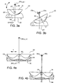
- FIGS. 3a and 3b are side elevation views of the artificial spinal disc according to the invention wherein the first and second plates are depicted in two different stages of articulation.
- FIGS. 4a and 4b are partial cross-sectional rear elevation views of the artificial spinal disc according to the invention wherein the first and second plates are depicted in two different stages of articulation.
- FIGS. 5a-5d are side elevation views of various different embodiments of the second plate according to the invention.
- FIG. 6a is a bottom plan view of the flat inferior surface of the second disc according to the invention.
- FIG. 6b is a sectional side elevation view along lines 6b-6b of the second plate depicted in FIG. 6a.
- Fig. 7 is a perspective view of a human spinal column having an articulating spinal disc according to the invention implanted therein.
- the artificial spinal disc of the invention is used as a substitute for a chronically degenerated, painful and/or ruptured and excised human intervertebral disc.
- the artificial spinal disc is essentially a kidney-shaped device, as viewed from a top plan view, comprising first (1) and second (10) kidney-shaped plates which can be placed between adjacent vertebrae (not shown) in a spine.
- Each of the first (1) and second (10) plates has an anterior end (A 1 and A 10 , respectively), an opposing posterior end (PS 1 and PS 10 , respectively), and two lateral sides (L 1 , L 2 and L 10 , L 12 , respectively).
- the first (1) and second (10) plates articulate with one another to form a human knee-type joint that permits limited rotation of the first (1) and second (10) plates relative to one another about a vertical axis (X 1 ).
- This limitation of rotation is within a physiologic range, i.e., from 0° - 10° of rotation or +/- 5 degrees off center in either direction, to provide moderate degrees of restraint to the device.
- the first plate (1) further comprises a substantially planar, or flat, first superior surface (2) and an opposing contoured or articulating first inferior surface (3) comprising two laterally juxtaposed convex portions (4, 5) of substantially the same shape.
- the second plate (10) further comprises a substantially planar, or flat, second inferior surface (11) and an opposing contoured or articulating second superior surface (12) comprising two laterally juxtaposed concave portions (13, 14) which are larger in size than the respective convex portions of the first plate (1).
- the first (1) and second (10) plates can be described by the frontal (or transverse) and median (or sagittal) sections of their respective articulating surfaces.
- the articulating first inferior surface (3) of the first plate (1) has a sagittal section, in the anterior to posterior direction along plane P 1 , resembling an outwardly curved arch, i.e. convex, having a varying radius of curvature.
- the condyles (4, 5) can each have a sagittal section, along the midpoint of each condyle (see the planes P 4 and P 5 , respectively), resembling a curve comprising at least a portion having a varying radius of curvature.
- the shape of the curve in the sagittal section will approximate the shape of a curve described by a Fibonacci mathematical series.
- the condyles (4, 5) can have a combined transverse section, in a lateral to lateral direction along plane P 2 , resembling a bimodal outwardly curved arch, i.e. two convex curves, having a varying radius of curvature.
- the plane P 2 is disposed approximately half way between the anterior (A 1 ) and posterior (PS 1 ) ends.
- the condyles (4, 5) can each have an individual transverse section, along plane P 2 , resembling a curve comprising at least a portion having a varying radius of curvature.
- the shape of the curve of the transverse section for each condyle (4,5) will approximate the shape of a curve described by a Fibonacci mathematical series.
- the articulating second superior surface (12) of the second plate (10) has a sagittal section, in an anterior to posterior direction along plane P 10 , resembling an inwardly curved arch, i.e., concave, having a varying radius of curvature.
- the modes (13, 14) can each have a sagittal section, along the midpoint of each mode (see the planes P 13 and P 14 , respectively), resembling a curve comprising at least a portion having a varying radius of curvature.
- the shape of the concave curves in the sagittal section will approximate the shape of a curve described by a Fibonacci mathematical series.
- the concave modes (13, 14) can have a combined transverse section, in a lateral to lateral direction along plane P 11 , resembling a bimodal inwardly curved arch, i.e. two concave curves.
- the plane P 11 is disposed approximately half way between the anterior (A 10 ) and posterior (PS 10 ) ends.
- the concave modes (13, 14) can each have an individual transverse section, along plane P 11 , resembling a curve comprising at least a portion having a varying radius of curvature.
- the shape of the curve of the transverse section for each concave mode (13, 14) will approximate the shape of a curve described by a Fibonacci mathematical series.
- the respective shapes of the concave and convex portions of the articulating surfaces (3, 12), respectively, will comprise portions that are substantially complementary; however, the articulating surfaces will be shaped to permit articulation of the plates (1) and (10) in a manner resembling the articulation of a human knee.
- the articulating surfaces (3, 12) can be regularly or irregularly shaped as at least partially complementary portions of spheroids, paraboloids, hyperboloids or ellipsoids of revolution or combinations thereof.
- the concave and convex portions of the articulating surfaces can be described by both coronal, i.e., transverse, and sagittal arcs which are variable, i.e., have varying radii of curvature, and allow for changing instant centers of rotation and moderate degrees of rotation during articulation of the surfaces (3, 12).
- the articulating surfaces (3) and (12) are designed so that the respective concave and convex portions thereof comprise a major portion of substantially the entirety of the respective articulating surfaces (3) and (12).
- the articulating surfaces are surrounded by respective surfaces defining the outer periphery of each of the respective plates (1) and (10), the articulating surfaces do not have respective inferior and superior surface portions that completely surround the articulating respective portions of said surfaces.
- substantially all of the convex-shaped portions (4, 5) of the articulating surface (3) can articulate with substantially all of the cave-shaped portions (13, 14) of the articulating surface (12).
- FIGS. 3a and 3b depict an artificial spinal disc (20) according to the invention comprising a superior first plate (21) and an inferior second plate (22).
- the first plate (21) comprises a first articular surface (25) which articulates with a second articular surface (26) of the second plate (22). Since FIG. 3a is a side elevation view of the artificial spinal disc (20), it corresponds to a lateral view of the device. Therefore, as the plates (21) and (22) articulate along their articulating surfaces (25) and (26), respectively, the first plate (21) will move in the direction indicated by the arrow (B) from the home position depicted in FIG. 3a to a second position depicted in FIG. 3b.
- the plates (21 and 22) share a common center of rotation (23a, 23b); however, when the first plate (21) is articulated to a second position as depicted in FIG. 3b, the instant centers of rotation (23a, 23b) are no longer coincident. Therefore, when a patient using the present device bends in a forward or backward manner, i.e., flexes in an anteroposterior fashion, the instant centers of rotation (23a, 23b) will be displaced away from each other in an anteroposterior fashion, i.e., there will be an anteroposterior translation of the instant center of rotation (23b) with respect to the instant center of rotation (23a).
- FIGS. 4a and 4b depict partial cross-sectional rear, or posterior, elevation views of an artificial spinal disc (30) comprising a first superior plate (31) and a second inferior plate (32).
- the first superior plate (31) comprises a bicondylar articulating surface which articulates with a bimodal concave articulating surface (34) of the second plate (32).
- the plates (31 and 32) are depicted in a home or neutral position; however, when the first plate (31) is translated laterally along the arrow (T) with respect to the second plate (32), the first plate (31) will tilt slightly with respect to the second plate (32) and the instant centers of rotation (35a, 35b) will be displaced from one another. Therefore, in one embodiment of the invention, the artificial spinal disc will comprise first and second articulating surfaces which are adapted to provide a changing center of rotation when the articulating surfaces are translated or articulated with respect to one another in a lateral-to-lateral fashion.
- FIGS. 5a-5d depict four additional embodiments (40, 45, 50, 55) of the second plate of the invention which comprises the bimodal concave shaped surface that engages with and articulates with a bicondylar or bimodal convex shaped surface of a first plate.
- the alternate embodiments of the vertebral end-plate, i.e., the second plate depict various embodiments where the rim-bearing and weight-bearing capacities of the artificial spinal disc have been enhanced. They include embodiments comprising pegged and concave configurations as well as an embodiment (50) comprising a central weight-bearing and contoured element (FIG.
- FIG. 5d depicts an alternate embodiment (55) having a porous surface (56) for the ingrowth of bone, such as by the additional of hydroxyapetite, to enhance the adhesion of the spinal disc to an adjacent vertebra.
- the embodiment of FIG. 5d is also adapted to reduce the effect of the moment to cause anterior extrusion of the implant via an increase in the frictional forces that resist this vector.
- 5a-5d also demonstrate the functional fixation provided by cancellous pitch and threaded fixation screws of various sizes, locations and directions that are envisioned to cause immediate fixation of the artificial spinal disc to adjacent vertebra and to prevent motion between the first and second plates of the artificial spinal disc.
- FIG. 6a depicts a bottom plan view of a second plate (60) according to the invention wherein the flat inferior surface of the plate that contacts an adjacent vertebra comprises a plurality of grooves, channels or wells (61) which provide for a macro-textured surface that is designed to enhance the survival of the subcondral structure of the end plate while distributing load to the vertebra.
- the curved and radiating grooves can prevent the congestion of the microvasculature associated with complete coverage and occlusion of the end plates.
- FIG. 6b is a sectional side elevation view of the second plate (60) of FIG. 6a.
- the plates (21 and 22) are adapted to articulate and rotate relative to one another about a lateral-to-lateral, or transverse, axis during anteroposterior flexion along the arrow (B).
- the first plate (21) is adapted to permit articulation in an anterior direction of up to about 15° from the neutral or home position shown in FIG. 3a and in a posterior direction of up to about -5° relative to the home position depicted in FIG. 3a.
- the artificial spinal disc (30) comprising a first plate (31) (shown in elevation) and a second plate (32) (shown in section) is adapted to permit articulation of the plates relative to one another about a median saggital axis which extends anteroposteriorly through the device.
- first plate (31) is displaced laterally, or is translated laterally, in the direction of the arrow (T)
- the instant center of rotation (35a and 35b) will be displaced relative to one another and the first plate (31) will assume a tilted position relative to the first plate (32).
- the articulating surfaces (33 and 34) each comprise portions having a varying radius of curvature
- the concave shaped sections of the articulating surface (34) each have a radius of curvature that is larger than a respective condyle portion of the articulating surface (33) with which it articulates.
- each concave shaped mode of the bimodal articulating surface (34) can comprise curved portions described by a Fibonacci mathematical series
- the corresponding convex shaped condyle of the articulating surface (33) will comprise curved portions which can be described by a second range of the Fibonacci mathematical series such that the radii of curvature of the convex shaped condyles will be smaller than the radii of curvature of the concave shaped modes.
- the degree of tilting of the first plate (31) relative to the second plate (32) will range from about 2-5° off center in either direction. In a preferred embodiment, the degree of tilting of the first plate (31) relative to the second plate (32) will range from 1-2.5°.
- the degree of anteroposterior flexion of the first plate (21) relative to the second plate (22) will range from about 3-15° in either direction, more preferably 1.5-7.5° in either direction, and more preferably will span 5-7°.
- the degree of anteroposterior flexion of the first plate (21) relative to the second plate (22) will have a maximum range of motion of about 10°, and more preferably about 5-7°.
- the average range of extension will be from 0 to -5° and more preferably from 0 to - 3°.
- Still yet another preferred embodiment provides an average flexion of about -5 to 10° along the saggital plane. It will be understood by the artisan of ordinary skill that a negative degrees indicates an extension of the spinal disc and a positive degrees indicates a flexion of the spinal disc, where flexion refers to bending the spine in a forward or anterior direction of.
- FIG. 7 depicts an artificial spinal disc (78) according to the invention implanted in a human spine (70) which comprises plural vertebrae (71, 72, 73, 74, 75) and plural interposed spinal discs (77a-77d).
- the artificial spinal disc (78) has a first plate (79) and a second plate (80) interposed the superior vertebra (72) and the inferior vertebra (71), respectively.
- the inferior surface (72a) of the superior vertebra (72) is depicted as planar, or flat, so as to optimize the substantially flat superior surface (79a) of the plate (79).
- the superior vertebral surface (71a) of the inferior vertebra (71) is also depicted as planar so as to optimize contact with the inferior surface (80a) of the plate (80).
- the plates (79 and 80) and consequently the vertebrae (72 and 71), respectively are held adjacent one another by the musculature and other body tissues which normally surround the spinal column (70).
- Each of the plates (1) and (10) can include attachment means which facilitate attachment of the artificial spinal disc to adjacent vertebrae.
- the attachment means comprises at least two projections (6, 7) and (16, 17) on each of the planar surfaces (2) and (11) of the plates (1) and (10), respectively.
- the projections (6, 7) mate with corresponding cavities (not shown) in adjacent vertebrae which are superior and inferior to the artificial spinal disc.
- the attachment means can also comprise multiple screw holes in the end of each plate (1, 10) through which are inserted respective cancellous screws that arc then screwed into the adjacent vertebral body that are in contact with the artificial spinal disc.
- attachment means can comprise one or more known means for affixing or attaching solids to one another.
- attachment means can include a screw, nail, rivet, adhesive, wire, band, strap, and embodiments for porous coating of the prosthesis endplate screws or the combination and locking mechanisms to affix the screw to the intervertebral disc component.
- the holes (8, 15), if present, can be shaped as desired. They can be adapted to receive and retain screws, nails, rivets, spikes and other articles used to secure the plates (1, 10, respectively) to adjacent vertebrae.
- the holes (8, 15) can be countersunk or can have locking methods or mechanisms which stabilize the screw to the artificial intervertebral disc prosthesis.
- FIGS. 1a-1b and 2a-2b depict the attachment means (6, 7 and 16, 17) on planar surfaces (2) and (11), respectively, as being disposed toward the anterior ends (A 1 ) and (A 10 ), respectively, the attachment means can be disposed anywhere within the artificial spinal disc. It will generally be necessary for each plate (1) and (10) to have at least one attachment means by which it is secured to an adjacent vertebra.
- the attachment means according to the invention can be shaped as desired in order to optimize performance in a particular use or environment.
- the attachment means can comprise plural similar or dissimilar attachment means.
- the attachment means will comprise two or more projections (6, 7) and (16, 17) on the planar surfaces (2) and (11), respectively for engagement with respective cavities or bores within adjacent inferior and superior surfaces of respective adjacent vertebrae.
- the planar surface can further comprise porous coatings to enhance ossication thereof such as by promoting the growth of bone therein. Osteoinductive, osteoconductive, osteogenic and other fusion enhancing materials are contemplated.
- FIGS. 1c and 2c depict a particular embodiment of a kidney shape
- the outer peripheries of the plates (1) and (10) of the artificial spinal disc can include embodiments wherein the anterior (A 2 and A 10 ), respectively, or posterior (PS 1 and PS 10 ), respectively, ends or the lateral sides (L 1 , L 2 ) and (L 10 , L 12 ), respectively, can have different or similar radii of curvature.
- the artificial spinal disc can be shaped additionally as a single condylar structure without limitation or need for an intercondylar notch to be integral in one part of the component.
- first superior (2) and second inferior (11) surface are intended to be flat, they can have depressions, ridges, ribs, bosses, projections, indentation, dimples and the like.
- the plates (1, 10) of the artificial spinal disc are generally intended to be rigid, semi-flexible or resilient and thus will comprise materials such as, by way of example and without limitation, metal, hard rubber, plastic, polymer, alloy, composite material, ceramic, ceramic metal alloy or combinations thereof.
- the plates (1, 10) can be manufactured by a variety of methods including: casting, stereolithography, machining, plasma spraying, coating, polishing, or investment casting.
- the plates (1, 10) are depicted as having lateral to lateral lengths greater than their respective anterior-to-posterior widths, the plates can be dimensioned as desired.
- the width of the plates (1, 10) can be greater than, equal to or less than the respective lengths.
- the superior-to-inferior height of each of the plates (1, 10) will be less than both its width and length.
- FIGS. 1a-1c and 2a-2c depict the first plate (1) as being the superior plate, the spinal disc of the invention can be flipped over so that the second plate (10) is the superior plate.
- the articulating spinal disc prosthesis of the invention differs from known prostheses used for the replacement of knee joints in at least one of the following ways.
- the present artificial spinal disc is smaller in construction, has a smaller articulating bicondylar surface, provides only a limited range of articulation in flexion and extension and can be designed such that the changing instant center of rotation will occur in either an anterior or posterior direction along a saggital plane.
- the change in the instant center of rotation of the artificial spinal disc will occur in a manner opposite that occurring in a human knee.
Claims (17)
- Künstliche Bandscheibe (1 ), die sich gelenkig bewegt, wobei die Scheibe umfasst:wobei:eine erste Platte (1) mit einem ersten Außenumfang, einer im Wesentlichen planen ersten oberen Fläche (2), einer ersten unteren Gelenkfläche (3), einem ersten vorderen Ende (A1), einem ersten hinteren Ende (PS1), einer ersten Längsseite (L1) und einer zweiten Längsseite (L2); undeine zweite Platte (10) mit einem zweiten Außenumfang, einer im Wesentlichen planen zweiten unteren Fläche (11), einer zweiten oberen Gelenkfläche (12), einem zweiten vorderen Ende (A10), einem zweiten hinteren Ende (PS10), einer dritten Längsseite (L10) und einer vierten Längsseite (L12);sich die erste und die zweite Platte (1, 10) gelenkig nach vorn und nach hinten bewegen können, wenn die erste untere Fläche (3), das erste vordere Ende (A1) und das erste hintere Ende (PS1) an die zweite obere Fläche (12), das zweite vordere Ende (A10) bzw. das zweite hintere Ende (PS10) angrenzend angeordnet werden; wobei die Scheibe eine momentane Drehmitte beim Biegen hat, die sich bei gelenkiger Vom-Hinten-Bewegung der Scheibe in einer Vom-Hinten-Richtung bewegt; dadurch gekennzeichnet, dass wenigstens die erste untere Gelenkfläche (3) oder die zweite obere Gelenkfläche (12) einen sich ändernden Vorn-Hinten-Krümmungsradiüs hat.
- Künstliche Bandscheibe nach Anspruch 1, wobei die sich gelenkig bewegende erste untere (3) und zweite obere Fläche (10) Hauptabschnitte haben, die im Wesentlichen komplementär sind.
- Künstliche Bandscheibe nach Anspruch 2, wobei der erste und der zweite Außenumfang im Wesentlichen nierenförmig sind.
- Künstliche Bandscheibe nach einem der vorangehenden Ansprüche, wobei die erste Platte (1) über der zweiten Platte (10) liegt.
- Künstliche Bandscheibe nach einem der vorangehenden Ansprüche, wobei die zweite Platte (10) über der ersten Platte (1) liegt.
- Künstliche Bandscheibe nach Anspruch 1, wobei die erste untere Gelenkfläche (3) zweigipflig konvex geformt ist und die zweite obere Gelenkfläche (12) zweigipflig konkav geformt ist.
- Künstliche Bandscheibe nach Anspruch 6, wobei ein erster Gipfel der zweigipfligen konvex geformten ersten unteren Fläche (3) im Wesentlichen ein Spiegelbild eines zweiten Gipfels der zweigipfligen konvex geformten ersten unteren Fläche (3) ist.
- Künstliche Bandscheibe nach Anspruch 6, wobei ein erster Gipfel der zweigipfligen konkav geformten zweiten oberen Fläche (12) im Wesentlichen ein Spiegelbild eines zweiten Gipfels der zweigipfligen konkav geformten zweiten oberen Fläche (12) ist.
- Künstliche Bandscheibe nach einem der vorangehenden Ansprüche, wobei die Bandscheibe zweiseitig symmetrisch ist.
- Künstliche Bandscheibe nach einem der vorangehenden Ansprüche, wobei die erste und die zweite Platte (1, 10) wenigstens eine Anbringungseinrichtung (6, 7, 16, 17) umfassen, noch besser zwei verschiedene Anbringungseinrichtungen.
- Künstliche Bandscheibe nach einem der vorangehenden Ansprüche, wobei wenigstens die erste oder die zweite Platte (1, 10) ein Loch (8, 15) zum Einsatz beim Befestigen wenigstens einer Platte an einem Wirbel enthält.
- Künstliche Bandscheibe nach einem der vorangehenden Ansprüche, wobei jeder Gipfel der zweigipfligen konvex geformten ersten unteren Fläche (3) entlang einer Mittellinie zwischen dem ersten vorderen (A1) und dem ersten hinteren Ende (PS1) angeordnet ist.
- Künstliche Bandscheibe nach einem der vorangehenden Ansprüche, wobei die erste und die zweite Platte (1, 10) Arten der gelenkigen Bewegung haben können, die ausgewählt werden aus:Verschiebung in einer Richtung von Seite zu Seite in Bezug zueinander; Drehung in Bezug zueinander um eine vertikale Achse und/oder gelenkige Hin- und Herbewegung nur von vom nach hinten und von hinten nach vom.
- Künstliche Bandscheibe nach Anspruch 6, wobei:die sich gelenkig bewegende zweigipflige konvex geformte erste untere Gelenkfläche (3) eine bikondyläre Struktur umfasst, wobei jeder Condylus (4, 5) den gleichen sich ändernden Krümmungsradius umfasst.
- Künstliche Bandscheibe nach Anspruch 14, wobei der Krümmungsradius eine mathematische Fibonacci-Folge beschreibt.
- Künstliche Bandscheibe nach Anspruch 15, wobei die Drehung so beschränkt ist, dass sie innerhalb eines normalen physiologischen Bereiches liegt.
- Künstliche Bandscheibe nach Anspruch 6, wobei die konvex geformte erste untere Fläche (3) und die konkav geformte zweite obere Fläche (12) durch veränderliche Coronal- und Sagittalbögen gebildet werden, die es ermöglichen, dass sich die erste und die zweite Platte (1, 10) relativ zueinander begrenzt um eine vertikale Achse drehen.
Applications Claiming Priority (3)
| Application Number | Priority Date | Filing Date | Title |
|---|---|---|---|
| US179324 | 1998-10-27 | ||
| US09/179,324 US6039763A (en) | 1998-10-27 | 1998-10-27 | Articulating spinal disc prosthesis |
| PCT/US1999/025099 WO2000024342A1 (en) | 1998-10-27 | 1999-10-26 | Articulating spinal disc prosthesis |
Publications (2)
| Publication Number | Publication Date |
|---|---|
| EP1124509A1 EP1124509A1 (de) | 2001-08-22 |
| EP1124509B1 true EP1124509B1 (de) | 2004-03-03 |
Family
ID=22656094
Family Applications (1)
| Application Number | Title | Priority Date | Filing Date |
|---|---|---|---|
| EP99956689A Expired - Lifetime EP1124509B1 (de) | 1998-10-27 | 1999-10-26 | Gelenkbandscheibenprothese |
Country Status (10)
| Country | Link |
|---|---|
| US (1) | US6039763A (de) |
| EP (1) | EP1124509B1 (de) |
| JP (1) | JP4159256B2 (de) |
| AT (1) | ATE260618T1 (de) |
| AU (1) | AU750180B2 (de) |
| BR (1) | BR9914810A (de) |
| CA (1) | CA2346378C (de) |
| DE (1) | DE69915330T2 (de) |
| ES (1) | ES2214899T3 (de) |
| WO (1) | WO2000024342A1 (de) |
Cited By (6)
| Publication number | Priority date | Publication date | Assignee | Title |
|---|---|---|---|---|
| DE10339170A1 (de) * | 2003-08-22 | 2005-03-24 | Aesculap Ag & Co. Kg | Zwischenwirbelimplantat |
| DE102007058304A1 (de) | 2007-12-04 | 2009-06-10 | Global Medical Consulting Gmbh | Bandscheibenprothese |
| US7655045B2 (en) | 2003-05-06 | 2010-02-02 | Aesculap Implant Systems, Llc | Artificial intervertebral disc |
| US7763076B2 (en) | 2003-04-04 | 2010-07-27 | Theken Spine, Llc | Artificial disc prosthesis |
| US7832409B2 (en) | 2003-05-06 | 2010-11-16 | Aesculap Implant Systems, Llc | Method of inserting an artificial intervertebral disc |
| US9579714B1 (en) | 2015-12-17 | 2017-02-28 | General Electric Company | Method and assembly for forming components having internal passages using a lattice structure |
Families Citing this family (355)
| Publication number | Priority date | Publication date | Assignee | Title |
|---|---|---|---|---|
| US7494507B2 (en) * | 2000-01-30 | 2009-02-24 | Diamicron, Inc. | Articulating diamond-surfaced spinal implants |
| US5836311A (en) * | 1995-09-20 | 1998-11-17 | Medtronic, Inc. | Method and apparatus for temporarily immobilizing a local area of tissue |
| US6679915B1 (en) * | 1998-04-23 | 2004-01-20 | Sdgi Holdings, Inc. | Articulating spinal implant |
| US6368350B1 (en) * | 1999-03-11 | 2002-04-09 | Sulzer Spine-Tech Inc. | Intervertebral disc prosthesis and method |
| CA2391330C (en) | 1999-07-02 | 2008-11-18 | Spine Solutions Inc. | Intervertebral implant |
| JP3282076B2 (ja) * | 1999-09-02 | 2002-05-13 | 桂一 花田 | 人体腰椎モデル構造およびその利用装置 |
| US7674293B2 (en) | 2004-04-22 | 2010-03-09 | Facet Solutions, Inc. | Crossbar spinal prosthesis having a modular design and related implantation methods |
| US7691145B2 (en) * | 1999-10-22 | 2010-04-06 | Facet Solutions, Inc. | Prostheses, systems and methods for replacement of natural facet joints with artificial facet joint surfaces |
| US8187303B2 (en) | 2004-04-22 | 2012-05-29 | Gmedelaware 2 Llc | Anti-rotation fixation element for spinal prostheses |
| US20050027361A1 (en) * | 1999-10-22 | 2005-02-03 | Reiley Mark A. | Facet arthroplasty devices and methods |
| EP1854433B1 (de) * | 1999-10-22 | 2010-05-12 | FSI Acquisition Sub, LLC | Facettenarthroplastiegeräte |
| US6811567B2 (en) * | 1999-10-22 | 2004-11-02 | Archus Orthopedics Inc. | Facet arthroplasty devices and methods |
| US6974478B2 (en) * | 1999-10-22 | 2005-12-13 | Archus Orthopedics, Inc. | Prostheses, systems and methods for replacement of natural facet joints with artificial facet joint surfaces |
| US20080177310A1 (en) * | 2000-10-20 | 2008-07-24 | Archus Orthopedics, Inc. | Facet arthroplasty devices and methods |
| US6679914B1 (en) | 2000-11-14 | 2004-01-20 | Shlomo Gabbay | Implantable orthopedic support apparatus |
| US6579319B2 (en) * | 2000-11-29 | 2003-06-17 | Medicinelodge, Inc. | Facet joint replacement |
| US20050080486A1 (en) * | 2000-11-29 | 2005-04-14 | Fallin T. Wade | Facet joint replacement |
| US6565605B2 (en) | 2000-12-13 | 2003-05-20 | Medicinelodge, Inc. | Multiple facet joint replacement |
| US6419703B1 (en) | 2001-03-01 | 2002-07-16 | T. Wade Fallin | Prosthesis for the replacement of a posterior element of a vertebra |
| US7169182B2 (en) * | 2001-07-16 | 2007-01-30 | Spinecore, Inc. | Implanting an artificial intervertebral disc |
| US8858564B2 (en) * | 2001-02-15 | 2014-10-14 | Spinecore, Inc. | Wedge plate inserter/impactor and related methods for use in implanting an artificial intervertebral disc |
| US8940047B2 (en) | 2001-02-15 | 2015-01-27 | Spinecore, Inc. | Intervertebral spacer device having recessed notch pairs for manipulation using a surgical tool |
| US6887274B2 (en) | 2001-02-15 | 2005-05-03 | Spinecore, Inc. | Intervertebral spacer device utilizing a belleville washer having radially spaced concentric grooves |
| US7223291B2 (en) * | 2001-07-16 | 2007-05-29 | Spinecore, Inc. | Intervertebral spacer device having engagement hole pairs for manipulation using a surgical tool |
| US6740117B2 (en) * | 2001-02-15 | 2004-05-25 | Spinecore, Inc. | Intervertebral spacer device having a radially thinning slotted belleville spring |
| US6863688B2 (en) | 2001-02-15 | 2005-03-08 | Spinecore, Inc. | Intervertebral spacer device utilizing a spirally slotted belleville washer having radially spaced concentric grooves |
| US6989032B2 (en) | 2001-07-16 | 2006-01-24 | Spinecore, Inc. | Artificial intervertebral disc |
| US6673113B2 (en) | 2001-10-18 | 2004-01-06 | Spinecore, Inc. | Intervertebral spacer device having arch shaped spring elements |
| US20050125064A1 (en) * | 2001-02-15 | 2005-06-09 | Spinecore, Inc. | Intervertebral spacer device |
| US6669730B2 (en) | 2001-02-15 | 2003-12-30 | Spinecore, Inc. | Intervertebral spacer device utilizing a spirally slotted belleville washer having radially extending grooves |
| US7563285B2 (en) | 2001-07-16 | 2009-07-21 | Spinecore, Inc. | Artificial intervertebral disc utilizing a ball joint coupling |
| US7604664B2 (en) | 2001-07-16 | 2009-10-20 | Spinecore, Inc. | Spinal baseplates with ball joint coupling and a retaining member |
| US7235081B2 (en) * | 2001-07-16 | 2007-06-26 | Spinecore, Inc. | Wedge plate inserter/impactor and related methods for use in implanting an artificial intervertebral disc |
| US6764515B2 (en) | 2001-02-15 | 2004-07-20 | Spinecore, Inc. | Intervertebral spacer device utilizing a spirally slotted belleville washer and a rotational mounting |
| US7115132B2 (en) | 2001-07-16 | 2006-10-03 | Spinecore, Inc. | Static trials and related instruments and methods for use in implanting an artificial intervertebral disc |
| WO2002065954A1 (en) * | 2001-02-16 | 2002-08-29 | Queen's University At Kingston | Method and device for treating scoliosis |
| US7090698B2 (en) * | 2001-03-02 | 2006-08-15 | Facet Solutions | Method and apparatus for spine joint replacement |
| US20050177238A1 (en) * | 2001-05-01 | 2005-08-11 | Khandkar Ashok C. | Radiolucent bone graft |
| US7695521B2 (en) | 2001-05-01 | 2010-04-13 | Amedica Corporation | Hip prosthesis with monoblock ceramic acetabular cup |
| US7776085B2 (en) * | 2001-05-01 | 2010-08-17 | Amedica Corporation | Knee prosthesis with ceramic tibial component |
| ATE419810T1 (de) * | 2001-05-01 | 2009-01-15 | Amedica Corp | Röntgendurchlässiges knochentransplantat |
| FR2824261B1 (fr) * | 2001-05-04 | 2004-05-28 | Ldr Medical | Prothese de disque intervertebral et procede et outils de mise en place |
| US6475219B1 (en) | 2001-06-07 | 2002-11-05 | Alexis P. Shelokov | Anterior vertebral protection method and device |
| AU2002324443A1 (en) * | 2001-06-14 | 2003-01-02 | Amedica Corporation | Metal-ceramic composite articulation |
| US6607558B2 (en) | 2001-07-03 | 2003-08-19 | Axiomed Spine Corporation | Artificial disc |
| US7635368B2 (en) * | 2001-07-16 | 2009-12-22 | Spinecore, Inc. | Intervertebral spacer device having simultaneously engageable angled perimeters for manipulation using a surgical tool |
| US8366775B2 (en) * | 2001-07-16 | 2013-02-05 | Spinecore, Inc. | Intervertebral spacer device having an angled perimeter for manipulation using a surgical tool |
| IL159459A0 (en) | 2001-07-16 | 2004-06-01 | Spinecore Inc | Artificial intervertebral disc having a wave washer force restoring element |
| US6527806B2 (en) | 2001-07-16 | 2003-03-04 | Third Millennium Engineering, Llc | Intervertebral spacer device having a spiral wave washer force restoring element |
| US7118599B2 (en) | 2001-07-16 | 2006-10-10 | Spinecore, Inc. | Artificial intervertebral disc |
| US6468310B1 (en) * | 2001-07-16 | 2002-10-22 | Third Millennium Engineering, Llc | Intervertebral spacer device having a wave washer force restoring element |
| US7160327B2 (en) | 2001-07-16 | 2007-01-09 | Spinecore, Inc. | Axially compressible artificial intervertebral disc having limited rotation using a captured ball and socket joint with a solid ball and compression locking post |
| US7771477B2 (en) | 2001-10-01 | 2010-08-10 | Spinecore, Inc. | Intervertebral spacer device utilizing a belleville washer having radially spaced concentric grooves |
| US7713302B2 (en) * | 2001-10-01 | 2010-05-11 | Spinecore, Inc. | Intervertebral spacer device utilizing a spirally slotted belleville washer having radially spaced concentric grooves |
| US7208014B2 (en) * | 2001-10-01 | 2007-04-24 | Spinecore, Inc. | Intervertebral spacer device utilizing a belleville washer having radially extending grooves |
| US20090177283A9 (en) * | 2001-10-01 | 2009-07-09 | Ralph James D | Intervertebral spacer device utilizing a spirally slotted belleville washer and a rotational mounting |
| WO2003032801A2 (en) * | 2001-10-18 | 2003-04-24 | Third Millennium Engineering Llc | Artificial intervertebral disc having a spider spring force restoring element |
| US6736850B2 (en) * | 2001-12-28 | 2004-05-18 | Spinal Concepts, Inc. | Vertebral pseudo arthrosis device and method |
| US20060129242A1 (en) * | 2001-12-28 | 2006-06-15 | Brian Bergeron | Pseudo arthrosis device |
| US6761723B2 (en) * | 2002-01-14 | 2004-07-13 | Dynamic Spine, Inc. | Apparatus and method for performing spinal surgery |
| US7708776B1 (en) | 2002-01-16 | 2010-05-04 | Nuvasive, Inc. | Intervertebral disk replacement system and methods |
| US7011684B2 (en) * | 2002-01-17 | 2006-03-14 | Concept Matrix, Llc | Intervertebral disk prosthesis |
| EP1501454A4 (de) * | 2002-02-07 | 2006-11-29 | Ebi Lp | Anteriores wirbelsäulenimplantat |
| US6824278B2 (en) * | 2002-03-15 | 2004-11-30 | Memx, Inc. | Self-shadowing MEM structures |
| US20080027548A9 (en) * | 2002-04-12 | 2008-01-31 | Ferree Bret A | Spacerless artificial disc replacements |
| US8038713B2 (en) * | 2002-04-23 | 2011-10-18 | Spinecore, Inc. | Two-component artificial disc replacements |
| US6706068B2 (en) * | 2002-04-23 | 2004-03-16 | Bret A. Ferree | Artificial disc replacements with natural kinematics |
| US20040236342A1 (en) * | 2002-04-23 | 2004-11-25 | Ferree Bret A. | Device to assess ADR motion |
| US7001433B2 (en) | 2002-05-23 | 2006-02-21 | Pioneer Laboratories, Inc. | Artificial intervertebral disc device |
| US8388684B2 (en) * | 2002-05-23 | 2013-03-05 | Pioneer Signal Technology, Inc. | Artificial disc device |
| US6770095B2 (en) | 2002-06-18 | 2004-08-03 | Depuy Acroned, Inc. | Intervertebral disc |
| US6793678B2 (en) | 2002-06-27 | 2004-09-21 | Depuy Acromed, Inc. | Prosthetic intervertebral motion disc having dampening |
| JP4456481B2 (ja) | 2002-08-15 | 2010-04-28 | ガーバー,デイヴィッド | 制御された人工椎間板インプラント |
| JP4256345B2 (ja) * | 2002-08-15 | 2009-04-22 | コップス,ジャスティン,ケー. | 椎間板インプラント |
| JP4210648B2 (ja) * | 2002-09-18 | 2009-01-21 | ジンテーズ ゲゼルシャフト ミト ベシュレンクテル ハフツング | 2部から成る関節を有するインプラント |
| EP2002805A3 (de) * | 2002-09-19 | 2009-01-07 | Malan De Villiers | Zwischenwirbelprothese |
| US6966929B2 (en) * | 2002-10-29 | 2005-11-22 | St. Francis Medical Technologies, Inc. | Artificial vertebral disk replacement implant with a spacer |
| US7497859B2 (en) * | 2002-10-29 | 2009-03-03 | Kyphon Sarl | Tools for implanting an artificial vertebral disk |
| US7083649B2 (en) * | 2002-10-29 | 2006-08-01 | St. Francis Medical Technologies, Inc. | Artificial vertebral disk replacement implant with translating pivot point |
| JP4654125B2 (ja) * | 2002-10-29 | 2011-03-16 | スパインコア,インコーポレイテッド | 人工椎間板を植え込む際に使用するための器具類、方法、および機能 |
| US7273496B2 (en) * | 2002-10-29 | 2007-09-25 | St. Francis Medical Technologies, Inc. | Artificial vertebral disk replacement implant with crossbar spacer and method |
| US20040133278A1 (en) * | 2002-10-31 | 2004-07-08 | Marino James F. | Spinal disc implant |
| FR2846550B1 (fr) | 2002-11-05 | 2006-01-13 | Ldr Medical | Prothese de disque intervertebral |
| WO2004058098A2 (en) * | 2002-12-17 | 2004-07-15 | Amedica Corporation | Total disc implant |
| US20040148028A1 (en) * | 2002-12-19 | 2004-07-29 | Ferree Bret A. | Artificial disc replacement (ADR) extraction methods and apparatus |
| GB0301085D0 (en) * | 2003-01-17 | 2003-02-19 | Krishna Manoj | Articulating spinal disc prosthesis |
| EP2329778A3 (de) * | 2003-01-31 | 2012-06-20 | Spinalmotion, Inc. | Anzeige für die Wirbelsäulenmittellinie |
| WO2004066884A1 (en) | 2003-01-31 | 2004-08-12 | Spinalmotion, Inc. | Intervertebral prosthesis placement instrument |
| AU2004212942A1 (en) | 2003-02-14 | 2004-09-02 | Depuy Spine, Inc. | In-situ formed intervertebral fusion device |
| AU2013200332B2 (en) * | 2003-03-06 | 2014-10-09 | Spinecore, Inc. | Cervical disc replacement |
| US6908484B2 (en) * | 2003-03-06 | 2005-06-21 | Spinecore, Inc. | Cervical disc replacement |
| AU2004220634B2 (en) * | 2003-03-06 | 2009-09-17 | Spinecore, Inc. | Instrumentation and methods for use in implanting a cervical disc replacement device |
| US20050049590A1 (en) * | 2003-03-07 | 2005-03-03 | Neville Alleyne | Spinal implant with securement spikes |
| US7419505B2 (en) * | 2003-04-22 | 2008-09-02 | Fleischmann Lewis W | Collapsible, rotatable, and tiltable hydraulic spinal disc prosthesis system with selectable modular components |
| US20050143824A1 (en) * | 2003-05-06 | 2005-06-30 | Marc Richelsoph | Artificial intervertebral disc |
| US7608104B2 (en) * | 2003-05-14 | 2009-10-27 | Archus Orthopedics, Inc. | Prostheses, tools and methods for replacement of natural facet joints with artifical facet joint surfaces |
| US20040230304A1 (en) * | 2003-05-14 | 2004-11-18 | Archus Orthopedics Inc. | Prostheses, tools and methods for replacement of natural facet joints with artifical facet joint surfaces |
| DE20308171U1 (de) * | 2003-05-21 | 2003-07-31 | Aesculap Ag & Co Kg | Wirbelkörperersatzimplantat |
| US10052211B2 (en) | 2003-05-27 | 2018-08-21 | Simplify Medical Pty Ltd. | Prosthetic disc for intervertebral insertion |
| WO2004105638A2 (en) | 2003-05-27 | 2004-12-09 | Spinalmotion, Inc. | Prosthetic disc for intervertebral insertion |
| US20090076614A1 (en) * | 2007-09-17 | 2009-03-19 | Spinalmotion, Inc. | Intervertebral Prosthetic Disc with Shock Absorption Core |
| US7575599B2 (en) * | 2004-07-30 | 2009-08-18 | Spinalmotion, Inc. | Intervertebral prosthetic disc with metallic core |
| US20050033338A1 (en) * | 2003-06-19 | 2005-02-10 | Ferree Bret A. | Surgical instruments particularly suited to severing ligaments and fibrous tissues |
| US20040267367A1 (en) | 2003-06-30 | 2004-12-30 | Depuy Acromed, Inc | Intervertebral implant with conformable endplate |
| DE10330698B4 (de) * | 2003-07-08 | 2005-05-25 | Aesculap Ag & Co. Kg | Zwischenwirbelimplantat |
| DE20310433U1 (de) | 2003-07-08 | 2003-09-04 | Aesculap Ag & Co Kg | Chirurgisches Instrument zum Handhaben eines Implantats |
| US7074238B2 (en) * | 2003-07-08 | 2006-07-11 | Archus Orthopedics, Inc. | Prostheses, tools and methods for replacement of natural facet joints with artificial facet joint surfaces |
| US7621956B2 (en) * | 2003-07-31 | 2009-11-24 | Globus Medical, Inc. | Prosthetic spinal disc replacement |
| US7713304B2 (en) | 2003-07-31 | 2010-05-11 | Globus Medical, Inc. | Transforaminal prosthetic spinal disc replacement |
| US7811329B2 (en) | 2003-07-31 | 2010-10-12 | Globus Medical | Transforaminal prosthetic spinal disc replacement and methods thereof |
| FR2858546B1 (fr) | 2003-08-04 | 2006-04-28 | Spine Next Sa | Prothese de disque intervertebral |
| US7799082B2 (en) | 2003-08-05 | 2010-09-21 | Flexuspine, Inc. | Artificial functional spinal unit system and method for use |
| US7909869B2 (en) | 2003-08-05 | 2011-03-22 | Flexuspine, Inc. | Artificial spinal unit assemblies |
| US7753958B2 (en) | 2003-08-05 | 2010-07-13 | Gordon Charles R | Expandable intervertebral implant |
| US20060229729A1 (en) * | 2003-08-05 | 2006-10-12 | Gordon Charles R | Expandable intervertebral implant for use with instrument |
| EP1651150B1 (de) * | 2003-08-07 | 2021-03-24 | Dynamic Spine, Inc. | Intervertebral-prothesenvorrichtung und relevante vorrichtungen und verfahren zur implantation der intervertebralen prothesenvorrichtung |
| US9254137B2 (en) * | 2003-08-29 | 2016-02-09 | Lanterna Medical Technologies Ltd | Facet implant |
| US7655012B2 (en) * | 2003-10-02 | 2010-02-02 | Zimmer Spine, Inc. | Methods and apparatuses for minimally invasive replacement of intervertebral discs |
| DE10347175B4 (de) * | 2003-10-08 | 2005-10-20 | Aesculap Ag & Co Kg | Zwischenwirbelimplantat |
| WO2005037135A2 (en) | 2003-10-14 | 2005-04-28 | The University Of Iowa Research Foundation | Ankle prosthesis and method for implanting ankle prosthesis |
| JP2007519429A (ja) * | 2003-10-17 | 2007-07-19 | スパインコア,インコーポレイテッド | 椎間板置換トライアル |
| US7628813B2 (en) * | 2003-10-20 | 2009-12-08 | Cervitech, Inc. | Cervical intervertebral prosthesis system |
| US9445916B2 (en) * | 2003-10-22 | 2016-09-20 | Pioneer Surgical Technology, Inc. | Joint arthroplasty devices having articulating members |
| US7320707B2 (en) * | 2003-11-05 | 2008-01-22 | St. Francis Medical Technologies, Inc. | Method of laterally inserting an artificial vertebral disk replacement implant with crossbar spacer |
| US7691146B2 (en) * | 2003-11-21 | 2010-04-06 | Kyphon Sarl | Method of laterally inserting an artificial vertebral disk replacement implant with curved spacer |
| US20050283237A1 (en) * | 2003-11-24 | 2005-12-22 | St. Francis Medical Technologies, Inc. | Artificial spinal disk replacement device with staggered vertebral body attachments |
| US20050209603A1 (en) * | 2003-12-02 | 2005-09-22 | St. Francis Medical Technologies, Inc. | Method for remediation of intervertebral disks |
| US20050154462A1 (en) * | 2003-12-02 | 2005-07-14 | St. Francis Medical Technologies, Inc. | Laterally insertable artificial vertebral disk replacement implant with translating pivot point |
| US7217291B2 (en) * | 2003-12-08 | 2007-05-15 | St. Francis Medical Technologies, Inc. | System and method for replacing degenerated spinal disks |
| US7588590B2 (en) | 2003-12-10 | 2009-09-15 | Facet Solutions, Inc | Spinal facet implant with spherical implant apposition surface and bone bed and methods of use |
| US20050143826A1 (en) * | 2003-12-11 | 2005-06-30 | St. Francis Medical Technologies, Inc. | Disk repair structures with anchors |
| US20050131406A1 (en) * | 2003-12-15 | 2005-06-16 | Archus Orthopedics, Inc. | Polyaxial adjustment of facet joint prostheses |
| US7901459B2 (en) * | 2004-01-09 | 2011-03-08 | Warsaw Orthopedic, Inc. | Split spinal device and method |
| US7556651B2 (en) * | 2004-01-09 | 2009-07-07 | Warsaw Orthopedic, Inc. | Posterior spinal device and method |
| US7550010B2 (en) * | 2004-01-09 | 2009-06-23 | Warsaw Orthopedic, Inc. | Spinal arthroplasty device and method |
| US7771479B2 (en) * | 2004-01-09 | 2010-08-10 | Warsaw Orthopedic, Inc. | Dual articulating spinal device and method |
| US20050171610A1 (en) * | 2004-01-09 | 2005-08-04 | Sdgi Holdings, Inc. | Mobile bearing spinal device and method |
| US7875077B2 (en) * | 2004-01-09 | 2011-01-25 | Warsaw Orthopedic, Inc. | Support structure device and method |
| US20050165407A1 (en) * | 2004-01-23 | 2005-07-28 | Diaz Robert L. | Disk arthroplasty instrumentation and implants |
| US20050165487A1 (en) * | 2004-01-28 | 2005-07-28 | Muhanna Nabil L. | Artificial intervertebral disc |
| PT2113227E (pt) | 2004-02-04 | 2015-10-16 | Ldr Medical | Prótese de disco intervertebral |
| FR2865629B1 (fr) | 2004-02-04 | 2007-01-26 | Ldr Medical | Prothese de disque intervertebral |
| US7846183B2 (en) * | 2004-02-06 | 2010-12-07 | Spinal Elements, Inc. | Vertebral facet joint prosthesis and method of fixation |
| US8900273B2 (en) * | 2005-02-22 | 2014-12-02 | Gmedelaware 2 Llc | Taper-locking fixation system |
| US8562649B2 (en) | 2004-02-17 | 2013-10-22 | Gmedelaware 2 Llc | System and method for multiple level facet joint arthroplasty and fusion |
| US8333789B2 (en) | 2007-01-10 | 2012-12-18 | Gmedelaware 2 Llc | Facet joint replacement |
| US7993373B2 (en) * | 2005-02-22 | 2011-08-09 | Hoy Robert W | Polyaxial orthopedic fastening apparatus |
| US7393361B2 (en) * | 2004-02-20 | 2008-07-01 | Spinecore, Inc. | Artificial intervertebral disc having a bored semispherical bearing with a compression locking post and retaining caps |
| AU2005216112B2 (en) * | 2004-02-20 | 2010-07-08 | Spinecore, Inc. | Artificial intervertebral disc having a universal joint |
| US7083651B2 (en) * | 2004-03-03 | 2006-08-01 | Joint Synergy, Llc | Spinal implant |
| US7195644B2 (en) * | 2004-03-02 | 2007-03-27 | Joint Synergy, Llc | Ball and dual socket joint |
| US7491239B2 (en) | 2005-02-23 | 2009-02-17 | Joint Synergy, Llc | Interior insert ball and dual socket joint |
| US7115144B2 (en) | 2004-03-02 | 2006-10-03 | Joint Synergy, Llc | Spinal implant |
| US8636802B2 (en) | 2004-03-06 | 2014-01-28 | DePuy Synthes Products, LLC | Dynamized interspinal implant |
| US20080082171A1 (en) * | 2004-04-22 | 2008-04-03 | Kuiper Mark K | Crossbar spinal prosthesis having a modular design and systems for treating spinal pathologies |
| US7051451B2 (en) * | 2004-04-22 | 2006-05-30 | Archus Orthopedics, Inc. | Facet joint prosthesis measurement and implant tools |
| US7406775B2 (en) * | 2004-04-22 | 2008-08-05 | Archus Orthopedics, Inc. | Implantable orthopedic device component selection instrument and methods |
| FR2869528B1 (fr) | 2004-04-28 | 2007-02-02 | Ldr Medical | Prothese de disque intervertebral |
| US20070093833A1 (en) * | 2004-05-03 | 2007-04-26 | Kuiper Mark K | Crossbar spinal prosthesis having a modular design and related implantation methods |
| US20050251175A1 (en) * | 2004-05-07 | 2005-11-10 | Ethicon Endo-Surgery, Inc. | Anchors for use in attachment of bladder tissues to pelvic floor tissues following a prostatectomy |
| US7338527B2 (en) * | 2004-05-11 | 2008-03-04 | Geoffrey Blatt | Artificial spinal disc, insertion tool, and method of insertion |
| US8764801B2 (en) * | 2005-03-28 | 2014-07-01 | Gmedelaware 2 Llc | Facet joint implant crosslinking apparatus and method |
| US7588578B2 (en) * | 2004-06-02 | 2009-09-15 | Facet Solutions, Inc | Surgical measurement systems and methods |
| US9504583B2 (en) | 2004-06-10 | 2016-11-29 | Spinal Elements, Inc. | Implant and method for facet immobilization |
| DE102004028967B4 (de) * | 2004-06-16 | 2006-05-24 | Aesculap Ag & Co. Kg | Zwischenwirbelimplantat |
| US8172904B2 (en) * | 2004-06-30 | 2012-05-08 | Synergy Disc Replacement, Inc. | Artificial spinal disc |
| EP1773256B1 (de) * | 2004-06-30 | 2019-11-27 | Synergy Disc Replacement Inc. | Künstliche bandscheibe |
| US9237958B2 (en) * | 2004-06-30 | 2016-01-19 | Synergy Disc Replacement Inc. | Joint prostheses |
| US8021428B2 (en) * | 2004-06-30 | 2011-09-20 | Depuy Spine, Inc. | Ceramic disc prosthesis |
| US20060009541A1 (en) * | 2004-07-09 | 2006-01-12 | Yih-Fang Chen | Saturant for friction material containing friction modifying layer |
| US20060025778A1 (en) * | 2004-07-21 | 2006-02-02 | Ferree Bret A | Methods and apparatus for artificial disc replacement (ADR) insertion and other surgical procedures |
| US20060020342A1 (en) * | 2004-07-21 | 2006-01-26 | Ferree Bret A | Facet-preserving artificial disc replacements |
| US7585326B2 (en) | 2004-08-06 | 2009-09-08 | Spinalmotion, Inc. | Methods and apparatus for intervertebral disc prosthesis insertion |
| US20060036327A1 (en) * | 2004-08-11 | 2006-02-16 | Albert Enayati | Prosthetic intervertebral disc implant |
| US20060041311A1 (en) * | 2004-08-18 | 2006-02-23 | Mcleer Thomas J | Devices and methods for treating facet joints |
| CA2576636A1 (en) * | 2004-08-18 | 2006-03-02 | Archus Orthopedics, Inc. | Adjacent level facet arthroplasty devices, spine stabilization systems, and methods |
| US8110003B2 (en) | 2004-09-09 | 2012-02-07 | University Of South Florida | Prostheses for spine discs having fusion capability |
| US20060069438A1 (en) * | 2004-09-29 | 2006-03-30 | Zucherman James F | Multi-piece artificial spinal disk replacement device with multi-segmented support plates |
| US7575600B2 (en) * | 2004-09-29 | 2009-08-18 | Kyphon Sarl | Artificial vertebral disk replacement implant with translating articulation contact surface and method |
| US7481840B2 (en) * | 2004-09-29 | 2009-01-27 | Kyphon Sarl | Multi-piece artificial spinal disk replacement device with selectably positioning articulating element |
| US20060079895A1 (en) * | 2004-09-30 | 2006-04-13 | Mcleer Thomas J | Methods and devices for improved bonding of devices to bone |
| US20060085075A1 (en) * | 2004-10-04 | 2006-04-20 | Archus Orthopedics, Inc. | Polymeric joint complex and methods of use |
| US20060085076A1 (en) * | 2004-10-15 | 2006-04-20 | Manoj Krishna | Posterior spinal arthroplasty-development of a new posteriorly inserted artificial disc and an artificial facet joint |
| US8721722B2 (en) | 2004-10-18 | 2014-05-13 | Ebi, Llc | Intervertebral implant and associated method |
| US20060085077A1 (en) * | 2004-10-18 | 2006-04-20 | Ebi, L.P. | Intervertebral implant and associated method |
| US20060265074A1 (en) | 2004-10-21 | 2006-11-23 | Manoj Krishna | Posterior spinal arthroplasty-development of a new posteriorly inserted artificial disc, a new anteriorly inserted artifical disc and an artificial facet joint |
| US8221461B2 (en) | 2004-10-25 | 2012-07-17 | Gmedelaware 2 Llc | Crossbar spinal prosthesis having a modular design and systems for treating spinal pathologies |
| WO2006050493A2 (en) * | 2004-11-03 | 2006-05-11 | The Regents Of The University Of Michigan | Biodegradable implant for intertransverse process fusion |
| US20070016196A1 (en) * | 2005-05-10 | 2007-01-18 | Winslow Charles J | Inter-cervical facet implant with implantation tool |
| US20060247633A1 (en) * | 2004-12-13 | 2006-11-02 | St. Francis Medical Technologies, Inc. | Inter-cervical facet implant with surface enhancements |
| US7776090B2 (en) * | 2004-12-13 | 2010-08-17 | Warsaw Orthopedic, Inc. | Inter-cervical facet implant and method |
| US8066749B2 (en) * | 2004-12-13 | 2011-11-29 | Warsaw Orthopedic, Inc. | Implant for stabilizing a bone graft during spinal fusion |
| US20060247650A1 (en) * | 2004-12-13 | 2006-11-02 | St. Francis Medical Technologies, Inc. | Inter-cervical facet joint fusion implant |
| US8029540B2 (en) | 2005-05-10 | 2011-10-04 | Kyphon Sarl | Inter-cervical facet implant with implantation tool |
| US8118838B2 (en) * | 2004-12-13 | 2012-02-21 | Kyphon Sarl | Inter-cervical facet implant with multiple direction articulation joint and method for implanting |
| US8100944B2 (en) * | 2004-12-13 | 2012-01-24 | Kyphon Sarl | Inter-cervical facet implant and method for preserving the tissues surrounding the facet joint |
| US20060149372A1 (en) * | 2004-12-17 | 2006-07-06 | Paxson Robert D | Artificial spinal disc |
| FR2879436B1 (fr) | 2004-12-22 | 2007-03-09 | Ldr Medical | Prothese de disque intervertebral |
| US20060247778A1 (en) * | 2005-01-26 | 2006-11-02 | Ferree Bret A | Intradiscal devices including spacers facilitating posterior-lateral and other insertion approaches |
| US8083797B2 (en) * | 2005-02-04 | 2011-12-27 | Spinalmotion, Inc. | Intervertebral prosthetic disc with shock absorption |
| US7722647B1 (en) | 2005-03-14 | 2010-05-25 | Facet Solutions, Inc. | Apparatus and method for posterior vertebral stabilization |
| JP2008534063A (ja) * | 2005-03-22 | 2008-08-28 | アーカス・オーソペディクス・インコーポレーテッド | 低侵襲性脊椎回復システム、装置、方法、及びキット |
| US8496686B2 (en) | 2005-03-22 | 2013-07-30 | Gmedelaware 2 Llc | Minimally invasive spine restoration systems, devices, methods and kits |
| US7753957B2 (en) * | 2005-03-24 | 2010-07-13 | Accelerated Innovation, Llc | Ball and Socket intervertebral disc replacement device with keyed surfaces assembly |
| US20060276801A1 (en) * | 2005-04-04 | 2006-12-07 | Yerby Scott A | Inter-cervical facet implant distraction tool |
| US20060235530A1 (en) * | 2005-04-18 | 2006-10-19 | Shelokov Alexis P | Artificial prosthesis |
| GB0508678D0 (en) | 2005-04-28 | 2005-06-08 | Cope Aiden | Motion segment intervertebral disc prosthesis |
| US8777959B2 (en) | 2005-05-27 | 2014-07-15 | Spinecore, Inc. | Intervertebral disc and insertion methods therefor |
| WO2006130796A2 (en) | 2005-06-02 | 2006-12-07 | Zimmer Spine, Inc. | Interbody fusion ring and method of using the same |
| FR2887762B1 (fr) | 2005-06-29 | 2007-10-12 | Ldr Medical Soc Par Actions Si | Instrumentation d'insertion de prothese de disque intervertebral entre des vertebres |
| US20070016190A1 (en) * | 2005-07-14 | 2007-01-18 | Medical Device Concepts Llc | Dynamic spinal stabilization system |
| US20070016301A1 (en) * | 2005-07-14 | 2007-01-18 | Medical Device Concepts Llc. | Multi-axial interbody spacer device |
| US8328851B2 (en) | 2005-07-28 | 2012-12-11 | Nuvasive, Inc. | Total disc replacement system and related methods |
| US7533672B2 (en) * | 2005-09-06 | 2009-05-19 | Synthes Usa, Llc | Methods and apparatus for vascular protection in spinal surgery |
| FR2891135B1 (fr) | 2005-09-23 | 2008-09-12 | Ldr Medical Sarl | Prothese de disque intervertebral |
| US20070093900A1 (en) * | 2005-09-26 | 2007-04-26 | Williams Lytton A | Modular articulating and fusion spinal disc implant system |
| US7927373B2 (en) | 2005-10-31 | 2011-04-19 | Depuy Spine, Inc. | Intervertebral disc prosthesis |
| FR2893838B1 (fr) * | 2005-11-30 | 2008-08-08 | Ldr Medical Soc Par Actions Si | Prothese de disque intervertebral et instrumentation d'insertion de la prothese entre les vertebres |
| WO2007126428A2 (en) * | 2005-12-20 | 2007-11-08 | Archus Orthopedics, Inc. | Arthroplasty revision system and method |
| US7662183B2 (en) * | 2006-01-24 | 2010-02-16 | Timothy Haines | Dynamic spinal implants incorporating cartilage bearing graft material |
| US7635389B2 (en) | 2006-01-30 | 2009-12-22 | Warsaw Orthopedic, Inc. | Posterior joint replacement device |
| US7811326B2 (en) * | 2006-01-30 | 2010-10-12 | Warsaw Orthopedic Inc. | Posterior joint replacement device |
| US20070233096A1 (en) * | 2006-02-13 | 2007-10-04 | Javier Garcia-Bengochea | Dynamic inter-spinous device |
| US8252058B2 (en) * | 2006-02-16 | 2012-08-28 | Amedica Corporation | Spinal implant with elliptical articulatory interface |
| US20070198093A1 (en) * | 2006-02-17 | 2007-08-23 | Amedica Corporation | Spinal implant with offset keels |
| WO2007096879A2 (en) * | 2006-02-23 | 2007-08-30 | Faneuil Innovations Investment Ltd. | Intervertebral disc replacement |
| US8118869B2 (en) * | 2006-03-08 | 2012-02-21 | Flexuspine, Inc. | Dynamic interbody device |
| WO2007106573A2 (en) * | 2006-03-15 | 2007-09-20 | Archus Orthopedics, Inc. | Facet and disc arthroplasty systems and methods |
| US8734519B2 (en) * | 2006-04-12 | 2014-05-27 | Spinalmotion, Inc. | Posterior spinal device and method |
| US20070270959A1 (en) * | 2006-04-18 | 2007-11-22 | Sdgi Holdings, Inc. | Arthroplasty device |
| US7905906B2 (en) * | 2006-06-08 | 2011-03-15 | Disc Motion Technologies, Inc. | System and method for lumbar arthroplasty |
| US7780676B2 (en) | 2006-07-11 | 2010-08-24 | Ebi, Llc | Intervertebral implantation apparatus |
| US8016886B2 (en) * | 2006-07-18 | 2011-09-13 | Altus Partners, Llc | Intervertebral disc replacement device |
| WO2008014258A2 (en) | 2006-07-24 | 2008-01-31 | Spine Solutions, Inc. | Intervertebral implant with keel |
| US20080027547A1 (en) * | 2006-07-27 | 2008-01-31 | Warsaw Orthopedic Inc. | Prosthetic device for spinal joint reconstruction |
| US20080051901A1 (en) | 2006-07-28 | 2008-02-28 | Spinalmotion, Inc. | Spinal Prosthesis with Multiple Pillar Anchors |
| US20080051900A1 (en) * | 2006-07-28 | 2008-02-28 | Spinalmotion, Inc. | Spinal Prosthesis with Offset Anchors |
| WO2008019397A2 (en) * | 2006-08-11 | 2008-02-14 | Archus Orthopedics, Inc. | Angled washer polyaxial connection for dynamic spine prosthesis |
| US20080045968A1 (en) * | 2006-08-18 | 2008-02-21 | Warsaw Orthopedic, Inc. | Instruments and Methods for Spinal Surgery |
| US8715350B2 (en) | 2006-09-15 | 2014-05-06 | Pioneer Surgical Technology, Inc. | Systems and methods for securing an implant in intervertebral space |
| US8377133B2 (en) * | 2006-09-15 | 2013-02-19 | Pioneer Surgical Technology, Inc. | Systems and methods for sizing, inserting and securing an implant in intervertebral space |
| EP2066267A4 (de) * | 2006-09-15 | 2013-03-06 | Pioneer Surgical Technology Inc | Systeme udnd verfahren für grössenanpassung, einsatz und fixierung eines implantats in einem zwischenwirbelraum |
| US20080177311A1 (en) * | 2006-10-30 | 2008-07-24 | St. Francis Medical Technologies, Inc. | Facet joint implant sizing tool |
| US8114159B2 (en) * | 2006-11-20 | 2012-02-14 | Depuy Spine, Inc. | Anterior spinal vessel protector |
| US8105382B2 (en) | 2006-12-07 | 2012-01-31 | Interventional Spine, Inc. | Intervertebral implant |
| US7905922B2 (en) | 2006-12-20 | 2011-03-15 | Zimmer Spine, Inc. | Surgical implant suitable for replacement of an intervertebral disc |
| US8075596B2 (en) * | 2007-01-12 | 2011-12-13 | Warsaw Orthopedic, Inc. | Spinal prosthesis systems |
| US9066811B2 (en) | 2007-01-19 | 2015-06-30 | Flexuspine, Inc. | Artificial functional spinal unit system and method for use |
| ES2905157T3 (es) | 2007-02-09 | 2022-04-07 | Dimicron Inc | Articulación de columna vertebral de múltiples lóbulos |
| US8465546B2 (en) | 2007-02-16 | 2013-06-18 | Ldr Medical | Intervertebral disc prosthesis insertion assemblies |
| US8992533B2 (en) | 2007-02-22 | 2015-03-31 | Spinal Elements, Inc. | Vertebral facet joint drill and method of use |
| US8652137B2 (en) | 2007-02-22 | 2014-02-18 | Spinal Elements, Inc. | Vertebral facet joint drill and method of use |
| US20080221680A1 (en) * | 2007-03-09 | 2008-09-11 | Zimmer Technology, Inc. | Optimized articular geometry |
| US10335288B2 (en) * | 2007-03-10 | 2019-07-02 | Spinesmith Partners, L.P. | Surgical implant secured by pegs and associated methods |
| US9358121B2 (en) * | 2007-03-10 | 2016-06-07 | Spinesmith Partners, L.P. | Artificial disc with unique articulating geometry and associated methods |
| US9289310B2 (en) | 2007-03-10 | 2016-03-22 | Spinesmith Partners, L.P. | Artificial disc with post and modular collar |
| US8864832B2 (en) | 2007-06-20 | 2014-10-21 | Hh Spinal Llc | Posterior total joint replacement |
| US8157819B2 (en) * | 2007-06-04 | 2012-04-17 | Brau Salvador A | Encasement prevention barrier for use in anterior lumbar surgery |
| FR2916956B1 (fr) * | 2007-06-08 | 2012-12-14 | Ldr Medical | Cage intersomatique,prothese intervertebrale,dispositif d'ancrage et instrumentation d'implantation |
| US10821003B2 (en) | 2007-06-20 | 2020-11-03 | 3Spline Sezc | Spinal osteotomy |
| US8900307B2 (en) | 2007-06-26 | 2014-12-02 | DePuy Synthes Products, LLC | Highly lordosed fusion cage |
| US20090043391A1 (en) | 2007-08-09 | 2009-02-12 | Spinalmotion, Inc. | Customized Intervertebral Prosthetic Disc with Shock Absorption |
| US8231676B2 (en) * | 2007-09-17 | 2012-07-31 | Pioneer Surgical Technology, Inc. | Motion preserving artificial intervertebral disc device |
| US8523912B2 (en) | 2007-10-22 | 2013-09-03 | Flexuspine, Inc. | Posterior stabilization systems with shared, dual dampener systems |
| US8187330B2 (en) * | 2007-10-22 | 2012-05-29 | Flexuspine, Inc. | Dampener system for a posterior stabilization system with a variable length elongated member |
| US8758441B2 (en) * | 2007-10-22 | 2014-06-24 | Spinalmotion, Inc. | Vertebral body replacement and method for spanning a space formed upon removal of a vertebral body |
| US8162994B2 (en) | 2007-10-22 | 2012-04-24 | Flexuspine, Inc. | Posterior stabilization system with isolated, dual dampener systems |
| US8157844B2 (en) | 2007-10-22 | 2012-04-17 | Flexuspine, Inc. | Dampener system for a posterior stabilization system with a variable length elongated member |
| US8182514B2 (en) | 2007-10-22 | 2012-05-22 | Flexuspine, Inc. | Dampener system for a posterior stabilization system with a fixed length elongated member |
| US8267965B2 (en) | 2007-10-22 | 2012-09-18 | Flexuspine, Inc. | Spinal stabilization systems with dynamic interbody devices |
| AU2008316600B2 (en) | 2007-10-25 | 2014-09-18 | Jeffery D. Arnett | Systems and methods for vertebral disc replacement |
| JP5677850B2 (ja) | 2007-12-28 | 2015-02-25 | シンセス ゲゼルシャフト ミット ベシュレンクテル ハフツングSynthes Gmbh | タックを患者の骨にインパクト駆動で打ち込むための結合体 |
| CN101909548B (zh) | 2008-01-17 | 2014-07-30 | 斯恩蒂斯有限公司 | 可膨胀椎间植入件以及制造它的相关方法 |
| CA2847598A1 (en) | 2008-01-18 | 2009-07-23 | Spinecore, Inc. | Instruments and methods for inserting artificial intervertebral implants |
| WO2009094477A1 (en) * | 2008-01-25 | 2009-07-30 | Spinalmotion, Inc. | Compliant implantable prosthetic joint with preloaded spring |
| US8764833B2 (en) * | 2008-03-11 | 2014-07-01 | Spinalmotion, Inc. | Artificial intervertebral disc with lower height |
| WO2009124269A1 (en) | 2008-04-05 | 2009-10-08 | Synthes Usa, Llc | Expandable intervertebral implant |
| US9034038B2 (en) * | 2008-04-11 | 2015-05-19 | Spinalmotion, Inc. | Motion limiting insert for an artificial intervertebral disc |
| KR20110009216A (ko) * | 2008-05-05 | 2011-01-27 | 스피날모우션, 인코포레이티드 | 폴리아릴에테르케톤 인공 추간판 |
| US9220603B2 (en) * | 2008-07-02 | 2015-12-29 | Simplify Medical, Inc. | Limited motion prosthetic intervertebral disc |
| EP2299944A4 (de) | 2008-07-17 | 2013-07-31 | Spinalmotion Inc | System zur platzierung künstlicher bandscheiben |
| EP2299941A1 (de) * | 2008-07-18 | 2011-03-30 | Spinalmotion Inc. | Bandscheibenprothese für die hintere wirbelsäule |
| CA2731048C (en) * | 2008-07-23 | 2016-11-29 | Marc I. Malberg | Modular nucleus pulposus prosthesis |
| US9364338B2 (en) | 2008-07-23 | 2016-06-14 | Resspond Spinal Systems | Modular nucleus pulposus prosthesis |
| EP2389126A4 (de) * | 2008-12-31 | 2013-10-30 | Spineology Inc | System und verfahren zur durchführung einer perkutanen wirbelkörperfusion |
| US9526620B2 (en) | 2009-03-30 | 2016-12-27 | DePuy Synthes Products, Inc. | Zero profile spinal fusion cage |
| US20110040331A1 (en) * | 2009-05-20 | 2011-02-17 | Jose Fernandez | Posterior stabilizer |
| WO2011005788A1 (en) | 2009-07-06 | 2011-01-13 | Synthes Usa, Llc | Expandable fixation assemblies |
| US9393129B2 (en) | 2009-12-10 | 2016-07-19 | DePuy Synthes Products, Inc. | Bellows-like expandable interbody fusion cage |
| US8979860B2 (en) | 2010-06-24 | 2015-03-17 | DePuy Synthes Products. LLC | Enhanced cage insertion device |
| US9907560B2 (en) | 2010-06-24 | 2018-03-06 | DePuy Synthes Products, Inc. | Flexible vertebral body shavers |
| TW201215379A (en) | 2010-06-29 | 2012-04-16 | Synthes Gmbh | Distractible intervertebral implant |
| US9402732B2 (en) | 2010-10-11 | 2016-08-02 | DePuy Synthes Products, Inc. | Expandable interspinous process spacer implant |
| US8668743B2 (en) | 2010-11-02 | 2014-03-11 | Adam D. Perler | Prosthetic device with multi-axis dual bearing assembly and methods for resection |
| US8353964B2 (en) | 2010-11-04 | 2013-01-15 | Carpenter Clyde T | Anatomic total disc replacement |
| US8852281B2 (en) | 2011-01-18 | 2014-10-07 | Globus Medical, Inc. | Artificial spinal disk prosthesis |
| US8740949B2 (en) | 2011-02-24 | 2014-06-03 | Spinal Elements, Inc. | Methods and apparatus for stabilizing bone |
| US9271765B2 (en) | 2011-02-24 | 2016-03-01 | Spinal Elements, Inc. | Vertebral facet joint fusion implant and method for fusion |
| USD724733S1 (en) | 2011-02-24 | 2015-03-17 | Spinal Elements, Inc. | Interbody bone implant |
| RU2550973C2 (ru) * | 2011-03-11 | 2015-05-20 | Фбс Девайс Апс | Позвоночный имплантат, инструмент для изготовления и способ применения |
| US8388687B2 (en) | 2011-03-25 | 2013-03-05 | Flexuspine, Inc. | Interbody device insertion systems and methods |
| US9144506B2 (en) | 2011-08-11 | 2015-09-29 | Jeff Phelps | Interbody axis cage |
| USD739935S1 (en) | 2011-10-26 | 2015-09-29 | Spinal Elements, Inc. | Interbody bone implant |
| US9017410B2 (en) | 2011-10-26 | 2015-04-28 | Globus Medical, Inc. | Artificial discs |
| US9526627B2 (en) | 2011-11-17 | 2016-12-27 | Exactech, Inc. | Expandable interbody device system and method |
| US9241807B2 (en) | 2011-12-23 | 2016-01-26 | Pioneer Surgical Technology, Inc. | Systems and methods for inserting a spinal device |
| WO2014018098A1 (en) | 2012-07-26 | 2014-01-30 | DePuy Synthes Products, LLC | Expandable implant |
| US9107763B2 (en) | 2012-10-04 | 2015-08-18 | DePuy Synthes Products, Inc. | Articulating intervertebral implant |
| US9750613B2 (en) * | 2012-11-12 | 2017-09-05 | Wright Medical Technology, Inc. | Stabilized total ankle prosthesis |
| US9492288B2 (en) | 2013-02-20 | 2016-11-15 | Flexuspine, Inc. | Expandable fusion device for positioning between adjacent vertebral bodies |
| US9717601B2 (en) | 2013-02-28 | 2017-08-01 | DePuy Synthes Products, Inc. | Expandable intervertebral implant, system, kit and method |
| US9522070B2 (en) | 2013-03-07 | 2016-12-20 | Interventional Spine, Inc. | Intervertebral implant |
| USD765853S1 (en) | 2013-03-14 | 2016-09-06 | Spinal Elements, Inc. | Flexible elongate member with a portion configured to receive a bone anchor |
| US9820784B2 (en) | 2013-03-14 | 2017-11-21 | Spinal Elements, Inc. | Apparatus for spinal fixation and methods of use |
| US9421044B2 (en) | 2013-03-14 | 2016-08-23 | Spinal Elements, Inc. | Apparatus for bone stabilization and distraction and methods of use |
| US9198770B2 (en) | 2013-07-31 | 2015-12-01 | Globus Medical, Inc. | Artificial disc devices and related methods of use |
| US9839450B2 (en) | 2013-09-27 | 2017-12-12 | Spinal Elements, Inc. | Device and method for reinforcement of a facet |
| US9456855B2 (en) | 2013-09-27 | 2016-10-04 | Spinal Elements, Inc. | Method of placing an implant between bone portions |
| US10398565B2 (en) | 2014-04-24 | 2019-09-03 | Choice Spine, Llc | Limited profile intervertebral implant with incorporated fastening and locking mechanism |
| US9517144B2 (en) | 2014-04-24 | 2016-12-13 | Exactech, Inc. | Limited profile intervertebral implant with incorporated fastening mechanism |
| US11478275B2 (en) | 2014-09-17 | 2022-10-25 | Spinal Elements, Inc. | Flexible fastening band connector |
| US9889016B2 (en) * | 2014-12-04 | 2018-02-13 | Ben Cannon | Adjustable total disc replacement device |
| WO2016122868A1 (en) | 2015-01-27 | 2016-08-04 | Spinal Elements, Inc. | Facet joint implant |
| US11426290B2 (en) | 2015-03-06 | 2022-08-30 | DePuy Synthes Products, Inc. | Expandable intervertebral implant, system, kit and method |
| US9913727B2 (en) | 2015-07-02 | 2018-03-13 | Medos International Sarl | Expandable implant |
| US9968991B2 (en) | 2015-12-17 | 2018-05-15 | General Electric Company | Method and assembly for forming components having internal passages using a lattice structure |
| US9987677B2 (en) | 2015-12-17 | 2018-06-05 | General Electric Company | Method and assembly for forming components having internal passages using a jacketed core |
| US10099284B2 (en) | 2015-12-17 | 2018-10-16 | General Electric Company | Method and assembly for forming components having a catalyzed internal passage defined therein |
| US10137499B2 (en) | 2015-12-17 | 2018-11-27 | General Electric Company | Method and assembly for forming components having an internal passage defined therein |
| US10046389B2 (en) | 2015-12-17 | 2018-08-14 | General Electric Company | Method and assembly for forming components having internal passages using a jacketed core |
| US10099283B2 (en) | 2015-12-17 | 2018-10-16 | General Electric Company | Method and assembly for forming components having an internal passage defined therein |
| US10118217B2 (en) | 2015-12-17 | 2018-11-06 | General Electric Company | Method and assembly for forming components having internal passages using a jacketed core |
| US10150158B2 (en) | 2015-12-17 | 2018-12-11 | General Electric Company | Method and assembly for forming components having internal passages using a jacketed core |
| US10099276B2 (en) | 2015-12-17 | 2018-10-16 | General Electric Company | Method and assembly for forming components having an internal passage defined therein |
| US10335853B2 (en) | 2016-04-27 | 2019-07-02 | General Electric Company | Method and assembly for forming components using a jacketed core |
| US10286450B2 (en) | 2016-04-27 | 2019-05-14 | General Electric Company | Method and assembly for forming components using a jacketed core |
| JP6995789B2 (ja) | 2016-06-28 | 2022-01-17 | イーアイティー・エマージング・インプラント・テクノロジーズ・ゲーエムベーハー | 拡張可能かつ角度調節可能な椎間ケージ |
| JP7019616B2 (ja) | 2016-06-28 | 2022-02-15 | イーアイティー・エマージング・インプラント・テクノロジーズ・ゲーエムベーハー | 関節運動式継手を備えた拡張可能かつ角度調節可能な椎間ケージ |
| US10537436B2 (en) | 2016-11-01 | 2020-01-21 | DePuy Synthes Products, Inc. | Curved expandable cage |
| US10888433B2 (en) | 2016-12-14 | 2021-01-12 | DePuy Synthes Products, Inc. | Intervertebral implant inserter and related methods |
| US10398563B2 (en) | 2017-05-08 | 2019-09-03 | Medos International Sarl | Expandable cage |
| US11344424B2 (en) | 2017-06-14 | 2022-05-31 | Medos International Sarl | Expandable intervertebral implant and related methods |
| US10940016B2 (en) | 2017-07-05 | 2021-03-09 | Medos International Sarl | Expandable intervertebral fusion cage |
| FR3070593A1 (fr) * | 2017-09-05 | 2019-03-08 | In2Bones | Prothese de cheville amelioree |
| JP2020533070A (ja) | 2017-09-08 | 2020-11-19 | パイオニア サージカル テクノロジー インコーポレイテッド | 椎間インプラント、器具、及び方法 |
| USD907771S1 (en) | 2017-10-09 | 2021-01-12 | Pioneer Surgical Technology, Inc. | Intervertebral implant |
| TWI786139B (zh) * | 2018-06-22 | 2022-12-11 | 財團法人工業技術研究院 | 人工關節 |
| US11446156B2 (en) | 2018-10-25 | 2022-09-20 | Medos International Sarl | Expandable intervertebral implant, inserter instrument, and related methods |
| US11457959B2 (en) | 2019-05-22 | 2022-10-04 | Spinal Elements, Inc. | Bone tie and bone tie inserter |
| EP3972503A4 (de) | 2019-05-22 | 2023-02-01 | Spinal Elements Inc. | Knochenbinder und einführvorrichtung für knochenbinder |
| US11452618B2 (en) | 2019-09-23 | 2022-09-27 | Dimicron, Inc | Spinal artificial disc removal tool |
| US11304733B2 (en) | 2020-02-14 | 2022-04-19 | Spinal Elements, Inc. | Bone tie methods |
| US11426286B2 (en) | 2020-03-06 | 2022-08-30 | Eit Emerging Implant Technologies Gmbh | Expandable intervertebral implant |
| US11850160B2 (en) | 2021-03-26 | 2023-12-26 | Medos International Sarl | Expandable lordotic intervertebral fusion cage |
| US11752009B2 (en) | 2021-04-06 | 2023-09-12 | Medos International Sarl | Expandable intervertebral fusion cage |
Family Cites Families (22)
| Publication number | Priority date | Publication date | Assignee | Title |
|---|---|---|---|---|
| US4257129A (en) * | 1979-05-21 | 1981-03-24 | Volz Robert G | Prosthetic knee joint tibial implant |
| CA1146301A (en) * | 1980-06-13 | 1983-05-17 | J. David Kuntz | Intervertebral disc prosthesis |
| US4309777A (en) | 1980-11-13 | 1982-01-12 | Patil Arun A | Artificial intervertebral disc |
| ATE44871T1 (de) * | 1984-09-04 | 1989-08-15 | Univ Berlin Humboldt | Bandscheibenendoprothese. |
| CA1283501C (en) | 1987-02-12 | 1991-04-30 | Thomas P. Hedman | Artificial spinal disc |
| CH672588A5 (de) * | 1987-07-09 | 1989-12-15 | Sulzer Ag | |
| FR2659226B1 (fr) | 1990-03-07 | 1992-05-29 | Jbs Sa | Prothese pour disques intervertebraux et ses instruments d'implantation. |
| GB9125798D0 (en) * | 1991-12-04 | 1992-02-05 | Customflex Limited | Improvements in or relating to spinal vertebrae implants |
| US5425773A (en) * | 1992-01-06 | 1995-06-20 | Danek Medical, Inc. | Intervertebral disk arthroplasty device |
| US5258031A (en) * | 1992-01-06 | 1993-11-02 | Danek Medical | Intervertebral disk arthroplasty |
| DE4208116C2 (de) * | 1992-03-13 | 1995-08-03 | Link Waldemar Gmbh Co | Bandscheibenendoprothese |
| DE4208115A1 (de) * | 1992-03-13 | 1993-09-16 | Link Waldemar Gmbh Co | Bandscheibenendoprothese |
| FR2694882B1 (fr) * | 1992-08-24 | 1994-10-21 | Sofamor | Prothèse discale intervertébrale. |
| JPH06178787A (ja) * | 1992-12-14 | 1994-06-28 | Shima Yumiko | 関節付椎体スペーサ、椎間腔計測器および椎体スペーサ模型 |
| US5425777A (en) * | 1992-12-23 | 1995-06-20 | Sarkisian; James S. | Artificial finger joint |
| US5676701A (en) * | 1993-01-14 | 1997-10-14 | Smith & Nephew, Inc. | Low wear artificial spinal disc |
| US5458642A (en) | 1994-01-18 | 1995-10-17 | Beer; John C. | Synthetic intervertebral disc |
| FR2724109A1 (fr) * | 1994-09-05 | 1996-03-08 | Medinov Sa | Prothese rachidienne intervertebrale a glissement notamment cervicale |
| FR2751202B1 (fr) * | 1996-07-22 | 2001-03-16 | Zacouto Fred | Implant squelettique |
| US5782832A (en) * | 1996-10-01 | 1998-07-21 | Surgical Dynamics, Inc. | Spinal fusion implant and method of insertion thereof |
| US5895428A (en) * | 1996-11-01 | 1999-04-20 | Berry; Don | Load bearing spinal joint implant |
| US5893889A (en) * | 1997-06-20 | 1999-04-13 | Harrington; Michael | Artificial disc |
-
1998
- 1998-10-27 US US09/179,324 patent/US6039763A/en not_active Expired - Fee Related
-
1999
- 1999-10-26 JP JP2000577959A patent/JP4159256B2/ja not_active Expired - Fee Related
- 1999-10-26 DE DE69915330T patent/DE69915330T2/de not_active Expired - Lifetime
- 1999-10-26 CA CA002346378A patent/CA2346378C/en not_active Expired - Fee Related
- 1999-10-26 ES ES99956689T patent/ES2214899T3/es not_active Expired - Lifetime
- 1999-10-26 AU AU13237/00A patent/AU750180B2/en not_active Ceased
- 1999-10-26 WO PCT/US1999/025099 patent/WO2000024342A1/en active IP Right Grant
- 1999-10-26 BR BR9914810-2A patent/BR9914810A/pt not_active IP Right Cessation
- 1999-10-26 AT AT99956689T patent/ATE260618T1/de not_active IP Right Cessation
- 1999-10-26 EP EP99956689A patent/EP1124509B1/de not_active Expired - Lifetime
Cited By (13)
| Publication number | Priority date | Publication date | Assignee | Title |
|---|---|---|---|---|
| US7771478B2 (en) | 2003-04-04 | 2010-08-10 | Theken Spine, Llc | Artificial disc prosthesis |
| US7763076B2 (en) | 2003-04-04 | 2010-07-27 | Theken Spine, Llc | Artificial disc prosthesis |
| US7763075B2 (en) | 2003-04-04 | 2010-07-27 | Theken Spine, Llc | Artificial disc prosthesis |
| US7771480B2 (en) | 2003-04-04 | 2010-08-10 | Theken Spine, Llc | Artificial disc prosthesis |
| US7806935B2 (en) | 2003-04-04 | 2010-10-05 | Theken Spine, Llc | Artificial disc prosthesis |
| US7655045B2 (en) | 2003-05-06 | 2010-02-02 | Aesculap Implant Systems, Llc | Artificial intervertebral disc |
| US7766966B2 (en) | 2003-05-06 | 2010-08-03 | Aesculap Implant Systems, Llc | Artificial intervertebral disc |
| US7832409B2 (en) | 2003-05-06 | 2010-11-16 | Aesculap Implant Systems, Llc | Method of inserting an artificial intervertebral disc |
| DE10339170B4 (de) * | 2003-08-22 | 2009-10-15 | Aesculap Ag | Zwischenwirbelimplantat |
| DE10339170A1 (de) * | 2003-08-22 | 2005-03-24 | Aesculap Ag & Co. Kg | Zwischenwirbelimplantat |
| DE102007058304A1 (de) | 2007-12-04 | 2009-06-10 | Global Medical Consulting Gmbh | Bandscheibenprothese |
| WO2009071044A1 (de) | 2007-12-04 | 2009-06-11 | Global Medical Consulting Gmbh | Bandscheibenprothese |
| US9579714B1 (en) | 2015-12-17 | 2017-02-28 | General Electric Company | Method and assembly for forming components having internal passages using a lattice structure |
Also Published As
| Publication number | Publication date |
|---|---|
| ATE260618T1 (de) | 2004-03-15 |
| US6039763A (en) | 2000-03-21 |
| CA2346378C (en) | 2007-07-31 |
| JP4159256B2 (ja) | 2008-10-01 |
| WO2000024342A9 (en) | 2000-10-19 |
| JP2002528171A (ja) | 2002-09-03 |
| BR9914810A (pt) | 2001-07-03 |
| ES2214899T3 (es) | 2004-09-16 |
| AU750180B2 (en) | 2002-07-11 |
| AU1323700A (en) | 2000-05-15 |
| WO2000024342A1 (en) | 2000-05-04 |
| DE69915330T2 (de) | 2005-02-17 |
| EP1124509A1 (de) | 2001-08-22 |
| DE69915330D1 (de) | 2004-04-08 |
| CA2346378A1 (en) | 2000-05-04 |
Similar Documents
| Publication | Publication Date | Title |
|---|---|---|
| EP1124509B1 (de) | Gelenkbandscheibenprothese | |
| US5562738A (en) | Intervertebral disk arthroplasty device | |
| EP1188423B1 (de) | Arthroplastische Vorrichtung für Zwischenwirbelscheiben | |
| CA2533473C (en) | Intervertebral implant comprising dome-shaped joint surfaces | |
| JP4965459B2 (ja) | 椎間補綴 | |
| US8066773B2 (en) | Artificial intervertebral disc | |
| US8092540B2 (en) | Implant comprising a two-piece joint | |
| US9060871B2 (en) | Total disc replacement device | |
| EP1737396A1 (de) | Künstliches implantat für orthopädische anwendungen | |
| WO2005094736A1 (en) | Contrained artificial spinal disc | |
| CA2298652A1 (en) | Multiple axis intervertebral prosthesis | |
| JP6629833B2 (ja) | 椎間板インプラント | |
| MXPA01004203A (de) |
Legal Events
| Date | Code | Title | Description |
|---|---|---|---|
| PUAI | Public reference made under article 153(3) epc to a published international application that has entered the european phase |
Free format text: ORIGINAL CODE: 0009012 |
|
| 17P | Request for examination filed |
Effective date: 20010430 |
|
| AK | Designated contracting states |
Kind code of ref document: A1 Designated state(s): AT BE CH CY DE DK ES FI FR GB GR IE IT LI LU MC NL PT SE |
|
| AX | Request for extension of the european patent |
Free format text: AL;LT;LV;MK;RO;SI |
|
| GRAH | Despatch of communication of intention to grant a patent |
Free format text: ORIGINAL CODE: EPIDOS IGRA |
|
| GRAS | Grant fee paid |
Free format text: ORIGINAL CODE: EPIDOSNIGR3 |
|
| GRAA | (expected) grant |
Free format text: ORIGINAL CODE: 0009210 |
|
| AK | Designated contracting states |
Kind code of ref document: B1 Designated state(s): AT BE CH CY DE DK ES FI FR GB GR IE IT LI LU MC NL PT SE |
|
| PG25 | Lapsed in a contracting state [announced via postgrant information from national office to epo] |
Ref country code: LI Free format text: LAPSE BECAUSE OF FAILURE TO SUBMIT A TRANSLATION OF THE DESCRIPTION OR TO PAY THE FEE WITHIN THE PRESCRIBED TIME-LIMIT Effective date: 20040303 Ref country code: IT Free format text: LAPSE BECAUSE OF FAILURE TO SUBMIT A TRANSLATION OF THE DESCRIPTION OR TO PAY THE FEE WITHIN THE PRESCRIBED TIME-LIMIT;WARNING: LAPSES OF ITALIAN PATENTS WITH EFFECTIVE DATE BEFORE 2007 MAY HAVE OCCURRED AT ANY TIME BEFORE 2007. THE CORRECT EFFECTIVE DATE MAY BE DIFFERENT FROM THE ONE RECORDED. Effective date: 20040303 Ref country code: FI Free format text: LAPSE BECAUSE OF FAILURE TO SUBMIT A TRANSLATION OF THE DESCRIPTION OR TO PAY THE FEE WITHIN THE PRESCRIBED TIME-LIMIT Effective date: 20040303 Ref country code: CY Free format text: LAPSE BECAUSE OF FAILURE TO SUBMIT A TRANSLATION OF THE DESCRIPTION OR TO PAY THE FEE WITHIN THE PRESCRIBED TIME-LIMIT Effective date: 20040303 Ref country code: CH Free format text: LAPSE BECAUSE OF FAILURE TO SUBMIT A TRANSLATION OF THE DESCRIPTION OR TO PAY THE FEE WITHIN THE PRESCRIBED TIME-LIMIT Effective date: 20040303 Ref country code: BE Free format text: LAPSE BECAUSE OF FAILURE TO SUBMIT A TRANSLATION OF THE DESCRIPTION OR TO PAY THE FEE WITHIN THE PRESCRIBED TIME-LIMIT Effective date: 20040303 Ref country code: AT Free format text: LAPSE BECAUSE OF FAILURE TO SUBMIT A TRANSLATION OF THE DESCRIPTION OR TO PAY THE FEE WITHIN THE PRESCRIBED TIME-LIMIT Effective date: 20040303 |
|
| REG | Reference to a national code |
Ref country code: GB Ref legal event code: FG4D |
|
| REG | Reference to a national code |
Ref country code: CH Ref legal event code: EP |
|
| REG | Reference to a national code |
Ref country code: IE Ref legal event code: FG4D |
|
| REF | Corresponds to: |
Ref document number: 69915330 Country of ref document: DE Date of ref document: 20040408 Kind code of ref document: P |
|
| PG25 | Lapsed in a contracting state [announced via postgrant information from national office to epo] |
Ref country code: SE Free format text: LAPSE BECAUSE OF FAILURE TO SUBMIT A TRANSLATION OF THE DESCRIPTION OR TO PAY THE FEE WITHIN THE PRESCRIBED TIME-LIMIT Effective date: 20040603 Ref country code: GR Free format text: LAPSE BECAUSE OF FAILURE TO SUBMIT A TRANSLATION OF THE DESCRIPTION OR TO PAY THE FEE WITHIN THE PRESCRIBED TIME-LIMIT Effective date: 20040603 Ref country code: DK Free format text: LAPSE BECAUSE OF FAILURE TO SUBMIT A TRANSLATION OF THE DESCRIPTION OR TO PAY THE FEE WITHIN THE PRESCRIBED TIME-LIMIT Effective date: 20040603 |
|
| LTIE | Lt: invalidation of european patent or patent extension |
Effective date: 20040303 |
|
| REG | Reference to a national code |
Ref country code: CH Ref legal event code: PL |
|
| REG | Reference to a national code |
Ref country code: ES Ref legal event code: FG2A Ref document number: 2214899 Country of ref document: ES Kind code of ref document: T3 |
|
| PG25 | Lapsed in a contracting state [announced via postgrant information from national office to epo] |
Ref country code: LU Free format text: LAPSE BECAUSE OF NON-PAYMENT OF DUE FEES Effective date: 20041026 |
|
| PG25 | Lapsed in a contracting state [announced via postgrant information from national office to epo] |
Ref country code: MC Free format text: LAPSE BECAUSE OF NON-PAYMENT OF DUE FEES Effective date: 20041031 |
|
| ET | Fr: translation filed | ||
| PLBE | No opposition filed within time limit |
Free format text: ORIGINAL CODE: 0009261 |
|
| STAA | Information on the status of an ep patent application or granted ep patent |
Free format text: STATUS: NO OPPOSITION FILED WITHIN TIME LIMIT |
|
| 26N | No opposition filed |
Effective date: 20041206 |
|
| PG25 | Lapsed in a contracting state [announced via postgrant information from national office to epo] |
Ref country code: PT Free format text: LAPSE BECAUSE OF NON-PAYMENT OF DUE FEES Effective date: 20040803 |
|
| PGFP | Annual fee paid to national office [announced via postgrant information from national office to epo] |
Ref country code: IE Payment date: 20091026 Year of fee payment: 11 Ref country code: ES Payment date: 20091026 Year of fee payment: 11 Ref country code: DE Payment date: 20091028 Year of fee payment: 11 |
|
| PGFP | Annual fee paid to national office [announced via postgrant information from national office to epo] |
Ref country code: NL Payment date: 20091024 Year of fee payment: 11 |
|
| PGFP | Annual fee paid to national office [announced via postgrant information from national office to epo] |
Ref country code: GB Payment date: 20091026 Year of fee payment: 11 Ref country code: FR Payment date: 20091201 Year of fee payment: 11 |
|
| REG | Reference to a national code |
Ref country code: NL Ref legal event code: V1 Effective date: 20110501 |
|
| GBPC | Gb: european patent ceased through non-payment of renewal fee |
Effective date: 20101026 |
|
| PG25 | Lapsed in a contracting state [announced via postgrant information from national office to epo] |
Ref country code: FR Free format text: LAPSE BECAUSE OF NON-PAYMENT OF DUE FEES Effective date: 20101102 |
|
| REG | Reference to a national code |
Ref country code: FR Ref legal event code: ST Effective date: 20110630 |
|
| REG | Reference to a national code |
Ref country code: IE Ref legal event code: MM4A |
|
| PG25 | Lapsed in a contracting state [announced via postgrant information from national office to epo] |
Ref country code: NL Free format text: LAPSE BECAUSE OF NON-PAYMENT OF DUE FEES Effective date: 20110501 Ref country code: GB Free format text: LAPSE BECAUSE OF NON-PAYMENT OF DUE FEES Effective date: 20101026 |
|
| REG | Reference to a national code |
Ref country code: DE Ref legal event code: R119 Ref document number: 69915330 Country of ref document: DE Effective date: 20110502 |
|
| PG25 | Lapsed in a contracting state [announced via postgrant information from national office to epo] |
Ref country code: IE Free format text: LAPSE BECAUSE OF NON-PAYMENT OF DUE FEES Effective date: 20101026 |
|
| REG | Reference to a national code |
Ref country code: ES Ref legal event code: FD2A Effective date: 20111118 |
|
| PG25 | Lapsed in a contracting state [announced via postgrant information from national office to epo] |
Ref country code: ES Free format text: LAPSE BECAUSE OF NON-PAYMENT OF DUE FEES Effective date: 20101027 |
|
| PG25 | Lapsed in a contracting state [announced via postgrant information from national office to epo] |
Ref country code: DE Free format text: LAPSE BECAUSE OF NON-PAYMENT OF DUE FEES Effective date: 20110502 |