EP1124506B1 - Medical graft connector and methods of making and installing same - Google Patents
Medical graft connector and methods of making and installing same Download PDFInfo
- Publication number
- EP1124506B1 EP1124506B1 EP99971690A EP99971690A EP1124506B1 EP 1124506 B1 EP1124506 B1 EP 1124506B1 EP 99971690 A EP99971690 A EP 99971690A EP 99971690 A EP99971690 A EP 99971690A EP 1124506 B1 EP1124506 B1 EP 1124506B1
- Authority
- EP
- European Patent Office
- Prior art keywords
- connector
- fingers
- conduit
- graft
- opposition
- Prior art date
- Legal status (The legal status is an assumption and is not a legal conclusion. Google has not performed a legal analysis and makes no representation as to the accuracy of the status listed.)
- Expired - Lifetime
Links
Images


Classifications
-
- A—HUMAN NECESSITIES
- A61—MEDICAL OR VETERINARY SCIENCE; HYGIENE
- A61F—FILTERS IMPLANTABLE INTO BLOOD VESSELS; PROSTHESES; DEVICES PROVIDING PATENCY TO, OR PREVENTING COLLAPSING OF, TUBULAR STRUCTURES OF THE BODY, e.g. STENTS; ORTHOPAEDIC, NURSING OR CONTRACEPTIVE DEVICES; FOMENTATION; TREATMENT OR PROTECTION OF EYES OR EARS; BANDAGES, DRESSINGS OR ABSORBENT PADS; FIRST-AID KITS
- A61F2/00—Filters implantable into blood vessels; Prostheses, i.e. artificial substitutes or replacements for parts of the body; Appliances for connecting them with the body; Devices providing patency to, or preventing collapsing of, tubular structures of the body, e.g. stents
- A61F2/82—Devices providing patency to, or preventing collapsing of, tubular structures of the body, e.g. stents
- A61F2/86—Stents in a form characterised by the wire-like elements; Stents in the form characterised by a net-like or mesh-like structure
- A61F2/88—Stents in a form characterised by the wire-like elements; Stents in the form characterised by a net-like or mesh-like structure the wire-like elements formed as helical or spiral coils
-
- A—HUMAN NECESSITIES
- A61—MEDICAL OR VETERINARY SCIENCE; HYGIENE
- A61B—DIAGNOSIS; SURGERY; IDENTIFICATION
- A61B17/00—Surgical instruments, devices or methods, e.g. tourniquets
- A61B17/11—Surgical instruments, devices or methods, e.g. tourniquets for performing anastomosis; Buttons for anastomosis
-
- A—HUMAN NECESSITIES
- A61—MEDICAL OR VETERINARY SCIENCE; HYGIENE
- A61B—DIAGNOSIS; SURGERY; IDENTIFICATION
- A61B17/00—Surgical instruments, devices or methods, e.g. tourniquets
- A61B17/064—Surgical staples, i.e. penetrating the tissue
-
- A—HUMAN NECESSITIES
- A61—MEDICAL OR VETERINARY SCIENCE; HYGIENE
- A61B—DIAGNOSIS; SURGERY; IDENTIFICATION
- A61B17/00—Surgical instruments, devices or methods, e.g. tourniquets
- A61B17/064—Surgical staples, i.e. penetrating the tissue
- A61B2017/0641—Surgical staples, i.e. penetrating the tissue having at least three legs as part of one single body
-
- A—HUMAN NECESSITIES
- A61—MEDICAL OR VETERINARY SCIENCE; HYGIENE
- A61B—DIAGNOSIS; SURGERY; IDENTIFICATION
- A61B17/00—Surgical instruments, devices or methods, e.g. tourniquets
- A61B17/11—Surgical instruments, devices or methods, e.g. tourniquets for performing anastomosis; Buttons for anastomosis
- A61B2017/1135—End-to-side connections, e.g. T- or Y-connections
-
- A—HUMAN NECESSITIES
- A61—MEDICAL OR VETERINARY SCIENCE; HYGIENE
- A61F—FILTERS IMPLANTABLE INTO BLOOD VESSELS; PROSTHESES; DEVICES PROVIDING PATENCY TO, OR PREVENTING COLLAPSING OF, TUBULAR STRUCTURES OF THE BODY, e.g. STENTS; ORTHOPAEDIC, NURSING OR CONTRACEPTIVE DEVICES; FOMENTATION; TREATMENT OR PROTECTION OF EYES OR EARS; BANDAGES, DRESSINGS OR ABSORBENT PADS; FIRST-AID KITS
- A61F2220/00—Fixations or connections for prostheses classified in groups A61F2/00 - A61F2/26 or A61F2/82 or A61F9/00 or A61F11/00 or subgroups thereof
- A61F2220/0008—Fixation appliances for connecting prostheses to the body
-
- A—HUMAN NECESSITIES
- A61—MEDICAL OR VETERINARY SCIENCE; HYGIENE
- A61F—FILTERS IMPLANTABLE INTO BLOOD VESSELS; PROSTHESES; DEVICES PROVIDING PATENCY TO, OR PREVENTING COLLAPSING OF, TUBULAR STRUCTURES OF THE BODY, e.g. STENTS; ORTHOPAEDIC, NURSING OR CONTRACEPTIVE DEVICES; FOMENTATION; TREATMENT OR PROTECTION OF EYES OR EARS; BANDAGES, DRESSINGS OR ABSORBENT PADS; FIRST-AID KITS
- A61F2230/00—Geometry of prostheses classified in groups A61F2/00 - A61F2/26 or A61F2/82 or A61F9/00 or A61F11/00 or subgroups thereof
- A61F2230/0002—Two-dimensional shapes, e.g. cross-sections
- A61F2230/0028—Shapes in the form of latin or greek characters
- A61F2230/005—Rosette-shaped, e.g. star-shaped
-
- A—HUMAN NECESSITIES
- A61—MEDICAL OR VETERINARY SCIENCE; HYGIENE
- A61F—FILTERS IMPLANTABLE INTO BLOOD VESSELS; PROSTHESES; DEVICES PROVIDING PATENCY TO, OR PREVENTING COLLAPSING OF, TUBULAR STRUCTURES OF THE BODY, e.g. STENTS; ORTHOPAEDIC, NURSING OR CONTRACEPTIVE DEVICES; FOMENTATION; TREATMENT OR PROTECTION OF EYES OR EARS; BANDAGES, DRESSINGS OR ABSORBENT PADS; FIRST-AID KITS
- A61F2230/00—Geometry of prostheses classified in groups A61F2/00 - A61F2/26 or A61F2/82 or A61F9/00 or A61F11/00 or subgroups thereof
- A61F2230/0002—Two-dimensional shapes, e.g. cross-sections
- A61F2230/0028—Shapes in the form of latin or greek characters
- A61F2230/0054—V-shaped
Definitions
- This invention relates to structures that can be used to make connections between tubular medical grafts and a patient's tubular body conduits.
- the invention also relates to methods for making and using the structures mentioned above.
- Tubular grafts are frequently needed in medical procedures.
- a coronary bypass procedure may involve the installation of a tubular graft between an aperture that has been formed in the side wall of the aorta and an aperture that has been formed in the side wall of a coronary artery downstream from an occlusion or blockage in that artery.
- Each end of the graft must be connected to the side wall of either the aorta or the coronary artery.
- Each such connection must extend annularly around the associated end of the graft conduit and be fluid-tight so that no blood will leak out.
- One common way to produce such connections is by suturing.
- the connector is preferably formed by using a highly elastic material such as nickel and titanium alloy (nitinol) metal.
- a first plurality of fingers is configured to engage an interior surface of the side wall of the existing conduit.
- a second plurality of fingers is configured to engage an exterior surface of the side wall of the existing conduit.
- a third plurality of fingers is received in an interior lumen of the graft conduit, and a fourth plurality of fingers is configured to pierce the graft conduit.
- the connector is radially deformable between a first size and a second size.
- the first, second and fourth pluralities of fingers are substantially radially aligned with respect to a longitudinal axis of the connector.
- the first and second pluralities of fingers may be resiliently deformable towards parallelism with the longitudinal axis of the connector.
- a substantially "U"-shaped configuration may be defined by adjacent, ones of the first and second plurality of fingers when viewed from a plane extending radially out from the longitudinal axis of the connector.
- a tubular graft conduit is attached to the connector.
- the first and second pluralities of fingers of the connector may be deflected inwardly toward parallelism with the longitudinal axis.
- the connector and graft conduit may be inserted in a delivery apparatus, which may maintain the fingers in their substantially axially extending condition.
- the delivery apparatus may then be inserted through the aperture in the side wall of the patient's tubular body conduit to which the end of the graft conduit is to be attached.
- the delivery apparatus is manipulated such that restraint is removed from the fingers of the connector. This permits the fingers to spring out to engage the tissue structure to which the connection is to be made.
- the delivery may be performed by passing the delivery structure intraluminally within the patient's tubular body conduit and through the wall of the body conduit to outside the conduit.
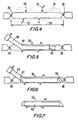
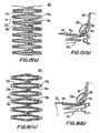
- FIG. 1 is a perspective view of an illustrative embodiment of a component of this invention.
- FIG. 2 is a simplified planar representation of the component of FIG. 1 .
- FIG. 3 is a side view in partial cross-section of the FIG. 1 component taken through lines 3-3 of FIG. 1 .
- FIG. 4 is a simplified elevational view of a graft conduit, during a first stage of processing the body conduit.
- FIG. 5 is a view similar to FIG. 4 , illustrating a subsequent stage of processing.
- FIG. 6 is a view similar to FIG. 5 , illustrating a further stage in such processing.
- FIG. 7 is a simplified elevational view, illustrating the body conduit after the processing of FIGS. 4-6 .
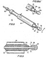
- FIG. 8 is a perspective view of apparatus according to the invention which is suitable for installing the component of FIG. 1 .
- FIG. 8(a) is a partial perspective view, similar to FIG. 8 , of an alternative embodiment of apparatus suitable for installing the component of FIG. 1 .
- FIG. 9 is a simplified sectional view of the component of FIG. 8 , taken along lines 9-9 of FIG. 8 .
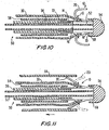
- FIG. 10 illustrates the FIG. 9 apparatus with a graft conduit added so that the FIG. 1 component can be used as a connector for the graft conduit.
- FIG. 11 is a simplified sectional view of the FIG. 9 apparatus with another component added to facilitate insertion in the patient.
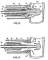
- FIG. 12 is a simplified sectional view of the FIG. 11 apparatus, illustrating a stage in the installation of the FIG. 1 component in a patient.
- FIG. 13 is a view similar to FIG. 12 , illustrating a further stage in the installation of the FIG. 1 component.
- FIG. 14 is an enlarged view similar to FIG. 13 , illustrating another further stage in the installation of the FIG. 1 component.
- FIG. 15(a) is a planar representation similar to FIG. 2 , illustrating another embodiment of the component of FIGS. 1-3 .
- FIG. 15(b) is a side view in partial cross-section similar to FIG. 14 , illustrating the component of FIG. 15(a) after processing and installation in the patient.
- FIG. 16(a) is a planar representation similar to FIG. 2 , illustrating another embodiment of the component of FIGS. 1-3 .
- FIG. 16(b) is a side view in partial cross-section similar to FIG. 14 , illustrating the component of FIG. 16(a) after processing and installation in the patient.
- FIG. 17(a) is a planar representation similar to FIG. 2 , illustrating another embodiment of the component of FIGS. 1-3 .
- FIG. 17(b) is a side view in partial cross-section similar to FIG. 14 , illustrating the component of FIG. 17(a) after processing and installation in the patient.
- FIG. 18(a) is a planar representation similar to FIG. 2 , illustrating another embodiment of the component of FIGS. 1-3 .
- FIG. 18(b) is a side view in partial cross-section similar to FIG. 14 , illustrating the component of FIG. 18(a) after processing and installation in the patient.
- FIG. 19(a) is a planar representation similar to FIG. 2 , illustrating another embodiment of the component of FIGS. 1-3 .
- FIG. 19(b) is an enlarged view of a portion of the component of FIG. 19 (a) .
- FIG. 19(c) is a side view in partial cross-section similar to FIG. 14 , illustrating the component of FIG. 19(a) after processing and installation in the patient.
- FIG. 20(a) is a planar representation similar to FIG. 2 , illustrating another embodiment of the component of FIGS. 1-3 .
- FIG. 20(b) is a side view in partial cross-section similar to FIG. 14 , illustrating the component of FIG. 20(a) after processing and installation in the patient.
- FIG. 21(a) is a planar representation similar to FIG. 2 , illustrating another embodiment of the component of FIGS. 1-3 .
- FIG. 21(b) is a side view in partial cross-section similar to FIG. 14 , illustrating the component of FIG. 21(a) after processing and installation in the patient.
- FIG. 21(c) is a side view similar to FIG. 21(b) , illustrating an alternative embodiment.
- FIG. 22(a) is a planar representation similar to FIG. 2 , illustrating another embodiment of the component of FIGS. 1-3 .
- FIG. 22(b) is a side view in partial cross-section similar to FIG. 14 , illustrating the component of FIG. 22(a) after processing and installation in the patient.
- FIG. 23(a) is a planar representation similar to FIG. 2 , illustrating another embodiment of the component of FIGS. 1-3 .
- FIG. 23(b) is a side view in partial cross-section similar to FIG. 14 , illustrating the component of FIG. 23(a) after processing and installation in the patient.
- FIG. 24 is cross-sectional view of an apparatus for installing the component of FIGS. 20(a)-20 (b ).
- FIG. 25 is a simplified schematic sectional view, illustrating a stage in the installation of the component of FIGS. 20(a)-20(b) .
- FIG. 26 is an enlarged sectional view, similar to FIG. 25 .
- FIG. 27 is an enlarged sectional view, similar to FIG. 26 , illustrating a later stage in the installation of the component of FIGS. 20(a)-20(b) .
- FIG. 28 is an enlarged sectional view, similar to FIG. 27 , illustrating yet a later stage in the installation of the component of FIGS. 20(a)-20(b) .
- FIG. 29 is an enlarged sectional view, similar to FIG. 28 , illustrating a further later stage in the installation of the component of FIGS. 20(a)-20 (b) .
- FIG. 30 is an enlarged sectional view, similar to FIG. 29 , illustrating another later stage in the installation of the component of FIGS. 20(a)-20(b) .
- FIG. 31 is an enlarged sectional view, similar to FIG. 30 , illustrating withdrawal of the FIG. 24 apparatus from the operative site.
- FIG. 32 is a planar representation similar to FIG. 17(a) , illustrating another embodiment of the component of FIGS. 1-3 .
- FIG. 33 is a side view in partial cross-section similar to FIG. 14 , illustrating the component of FIG. 32 after processing.
- FIG. 34 is a simplified schematic sectional view, illustrating a stage in the installation of the component of FIG. 32 .
- FIG. 35 is an enlarged sectional view, similar to FIG. 34 .
- FIG. 36 is an enlarged sectional view, similar to FIG. 35 , illustrating a later stage in the installation of the component of FIG. 32 .
- FIG. 37 is an enlarged sectional view, similar to FIG. 36 , illustrating yet a later stage in the installation of the component of FIG. 32 .
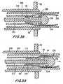
- FIG. 38 is a simplified sectional view of the component of FIG. 32 and a graft conduit mounted in the FIG. 24 apparatus, illustrating a stage in the installation of the FIG. 32 component in the patient.
- FIG. 39 is a simplified sectional view similar to FIG. 38 , illustrating a further stage in the installation.
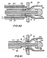
- FIG. 40 is a simplified sectional view similar to FIG. 39 , illustrating another stage in the installation.
- FIG. 41 is a simplified sectional view similar to FIG. 40 , illustrating yet another stage in the installation.
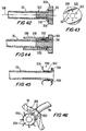
- FIG. 42 is a simplified sectional view of a graft conduit, and an apparatus for installing a component on the graft conduit.
- FIG. 43 is a simplified elevational view of the apparatus of FIG. 42 .
- FIG. 44 is a sectional view similar to FIG. 42 , illustrating a stage in the installation of a component on the graft conduit.
- FIG. 45 is a view similar to FIG. 44 , illustrating a component in accordance with the invention installed in the graft conduit.
- FIG. 46 is a simplified perspective view in partial cross-section, illustrating the graft conduit and component of FIGS. 42-43 installed in the tubular body conduit.
- FIG. 1 illustrates a preferred embodiment of a connector 10 for use in connecting an end portion of a tubular graft conduit to a side wall of a patient's tubular body conduit.
- connector 10 is formed with a substantially radial configuration having a band portion 11 defining a central aperture 12 about which a plurality of components, or fingers, are oriented radially and axially outward from the band portion.
- the band 11 is configured for coaxial mounting with respect to the end portion of a graft conduit, and the fingers are configured to engage the side wall of a tubular body conduit through an aperture in that side wall.
- the band 11 is composed of a plurality of internal struts 14.
- the internal struts 14 are configured to engage one side of the wall of a graft conduit.
- Engagement members 16 extend radially outward and assist to secure the graft conduit to the connector 10, as will be described in greater detail below.
- a plurality of internal opposition fingers 18 are positioned adjacent a plurality of external opposition fingers 20 and extend radially and axially outward from an end portion of the band 11.
- the internal 18 and external fingers 20 are configured to engage both the inside and the outside wall of a second tubular conduit, typically a body conduit.
- connector 10 is preferably fabricated from a single piece of material as a single, integral unit.
- FIG. 2 illustrates a planar representation of the connector of this invention shown in FIGS. 1 and 3 .
- Component 10 may be formed from a sheet of material, which is preferably highly elastic.
- a particularly preferred material is nickel titanium alloy (nitinol) metal, but other materials such as stainless steel or thermoplastics may be used instead if desired.
- the starting sheet may have any length, diameter, and wall thickness suitable for the intended use of the finished connector. For example, the thickness of the sheet and the length of the struts and opposition fingers may be determined by the size of the body conduits joined or the pressure of fluids passing therethrough.
- band 11 may have a nominal diameter 24 of about 4.0 millimeters, a wall thickness of about 0.08 millimeters (0.003 inches), and a length of about 7.0 millimeters. It will be understood, however, that these specific dimensions are only exemplary, and that any other dimensions can be used instead if desired.
- a first step in manufacturing component 10 in accordance with the invention is to form the sheet into a cylindrical tube.
- the next step involves cutting or machining the tube.
- the following cutting steps may be performed simultaneously, or in any order deemed appropriate by one skilled in the art.
- the axial end portions of the' sheet are substantially axially cut to provide a plurality of fingers.
- Substantially axial "U"-shaped cuts may be made at spaced intervals in order to provide a separation between the fingers.
- the internal opposition fingers 18 and engagement members 16 are formed by such cutting and extend substantially axially from the band portion 11. As will be described below, internal opposition fingers 18 and engagement members 16 define the distal portion of the connector.
- a second set of fingers is cut from the band portion 11, i.e., a medial portion of the sheet, or tube. More particularly, a series of substantially axial "U"-shaped cuts are made in the sheet to define external opposition fingers 20.
- Each "U"-shaped cut includes two elongated axial cuts which may extend from one axial end portion of the sheet to the other end portion, and a shorter transverse cut adjacent one end portion of the sheet to provide the "U" configuration. (The cut may remove material from the sheet, as shown in the FIG.)
- the external opposition finger 20 thus defined has an end portion 23 integral with an internal opposition finger 18. Fingers 20 are substantially longer than fingers 18 in order to be partially coextensive with fingers 18 (see FIG. 3 ) and to provide contact surfaces with both the graft conduit and the body conduit, as will be described below.
- Each external opposition finger 20 is "U"-shaped in the plan view due to a medial aperture 22 defined in the center of each of the fingers 20.
- band portion 11 has a substantially "zigzag" configuration for coaxial mounting with respect to the tubular graft portion, including struts 14 and intermediate strap portions 19 defined between each set of internal struts 14.
- the combination of the resiliency of the component material, axial cuts, "U"-shaped cuts, and apertures 22 allows radial contraction and expansion of the diameter 24 of band 11, and therefore of component 10, during delivery and deployment, as will be described in greater detail below.
- the starting tube is machined into the configuration (represented as a plane in FIG. 2 ) by laser cutting, electron discharge machining (EDM), or etching.
- the machining may be performed either in the cylindrical tubular configuration or in the sheet configuration, depending upon the requirements of the materials and machining methods. Material not shown in FIG. 2 is subsequently removed from the starting sheet to provide the geometry shown in the FIG.
- the next step is to deflect fingers on the machined tube to approximately the positions that are desired in the finished and installed connector.
- FIG. 3 shows resilient fingers 20 and 18 extending radially and axially outward from an end portion of band 11.
- the machined tube is placed in a mold and heat-shaped into a geometry approximately that which the component 10 will assume after deployment. It will be appreciated that it may be desirable to deflect fingers 18 and 20 beyond their desired positions so that when they are substantially released during deployment, they will resiliently bear on the tissue in which the connector is installed in their effort to return to the positions to which they have been deflected in this step of their manufacture.
- the shape is retained after removing component 10 from the mold due to the properties of the NiTi material.
- the connector can be cooled to improve malleability to aid in positioning into the mold or during delivery.
- adjacent ones of fingers 18 and 20 likewise define a "U"-shaped configuration when viewed from a plane extending radially out from the band portion 11.
- the "U" configuration may also form an angle 19 less than a right angle with the axis 11 (typically 20°-90°), as will be described in greater detail below.
- Connector 10 defines a nominal diameter 24. It is contemplated that nominal diameter 24 is selected to be marginally greater than the internal diameter of the graft conduit, such that the internal struts 14 bear on the interior of graft when they are positioned inside the graft. Apertures 22, as well as the resilient material selected for the connector 10, permit the expansion and reduction of the diameter from the nominal diameter 24.
- Connector 10 subsequent to formation, above, is used to join a graft conduit and a tubular body conduit in an end-to-side anastomosis.
- the graft conduit may be a natural conduit (e.g., a relocated portion of the patient's tubular body tissue), an artificial conduit (e.g., of the type shown in above-mentioned U.S. Patent 5,976,178 ), or a composite of natural and artificial conduits.
- FIGS. 4-7 show apparatus and methods to prepare, and in some cases, remove a body conduit for use as the graft conduit.
- FIG. 4 illustrates conduit 30 disposed within the body and typically serving as a conduit for fluid, e.g., blood.
- the conduit 30 has a plurality of side branches 32 for transporting fluid between the conduit 30 and the surrounding tissue 34.
- the conduit 30 is an external jugular vein. A portion of the conduit is exposed. In this embodiment, approximately 15 cm of the vein is exposed.
- a first, or cranial location 36 is selected.
- a second, or caudal location 38 is likewise selected. The first 36 and second locations 38 are spaced apart by a length 39, e.g.
- the graft conduit 30 is ligated, clipped, or otherwise closed at the first 36 and second locations 38.
- the side branches 32 protruding from the vein body are subsequently ligated and cut.
- an introducer 40 having a diameter 42 of approximately 3 French, is inserted into the graft conduit 30 at a point 44 slightly distal of the first location 36.
- the introducer 40 is advanced distally to a position adjacent the second location 38.
- An end portion of the introducer 40 remains outside the graft conduit 30.
- the conduit 30 is provided with a first cut 46 defining an oblique angle of approximately 45° with respect to the conduit axis adjacent the second location 38 ( FIG. 6 ). It is contemplated that this procedure may be used for a conduit which is not entirely removed from its original location.
- the internal mammary artery (IMA) is used as a blood source in coronary artery bypass procedures by cutting one end of the IMA and connecting that end to the coronary artery downstream of an occlusion by end-to-side anastomosis.
- a second cut 47 is made at approximately a 90° angle with respect to the axis adjacent the first location 36. This second cut 47 passes through both the graft 30 and introducer 40.
- the cut portion of the introducer 40 outside the graft conduit 30 is discarded.
- the graft 30 and introducer 40 are removed such that the introducer 40 remains within the graft 30 ( FIG. 7 ), and both graft 30 and introducer 40 are placed in an appropriate solution.
- the graft 30 is to be used for connection to the side wall of the tubular body conduit.
- Connector 10 may be installed to join two tubular conduits using several techniques.
- An exemplary apparatus 50 for installing connector 10 in the patient is illustrated in FIG. 8 .
- Apparatus 50 may be used in minimally invasive surgical procedures, wherein an incision, access trocar or other small entry opening is provided in the patient's body. Such opening should be sized to permit insertion of the instrument 50 to the site wherein the anastomosis of the tubular conduits is to take place.
- apparatus 50 may be used in conventional surgical techniques where full access and direct visualization are appropriate.
- apparatus 50 may also be used in a procedure wherein connector 10 is deployed from inside the lumen of a body conduit to the outside thereof.
- FIG. 8 illustrates apparatus 50 prior to the mounting of component 10 therein.
- Apparatus 50 includes a number of coaxial sleeves which are relatively axially slidable and angularly rotatable. Preferably, the sleeves are actuable by the physician from the proximal end portion of the instrument.
- An inner rod 52 is provided with a distal tip 54.
- An atraumatic end 59 of distal tip 54 may be curved or conical to facilitate insertion into an aperture in the side wall of a tubular body conduit. If the conduit is particularly delicate or susceptible to collapse, the distal tip may be provided with more gradual taper as deemed appropriate by the physician.
- Surrounding inner rod 52 is an intermediate sleeve 56.
- intermediate sleeve 56 is an outer sleeve 58.
- At least the distal end portions of inner rod 52, intermediate sleeve 56, and outer sleeve 58 are preferably manufactured from a rigid material such a metal or a surgical grade plastic material.
- Locking mechanism 60 is provided to releasably secure inner rod 52 with respect to intermediate sleeve 56.
- locking mechanism 62 releasably secures intermediate sleeve 56 with respect to outer sleeve 58.
- Locking mechanisms 60 and 62 may be manufactured in accordance with any type of mechanism known in the art, such as a releasable clamp or friction fitting, set screw, or bayonet mount.
- Locking mechanisms 60 and 62 are advantageously selected to maintain the small overall diameter of apparatus 50.
- Sheath 64 is provided to surround outer sleeve 58. Sheath 64, which also protects the graft conduit from damage during the anastomosis, may be fabricated from a flexible material, such as a polymer.
- apparatus 50a substantially identical to apparatus 50, is provided with a crenelated configuration 53 on end portions of outer sheath 64a, outer sleeve 58a and distal tip portion 54a.
- the crenelated configuration 53 defines a series of alternating protrusions 55 and notches 57, which cooperate with fingers 14, 18 and 20 of component 10, as will be described in greater detail below.
- the various components of apparatus 50a are configured for both axial movement and angular rotation. It is contemplated that remote rotation of the components of apparatus 50a is enabled by various rotation devices, such as collars or knobs known in the art, provided at the proximal end of the device (not shown).
- FIG. 9 further illustrates the relative positioning of the components of apparatus 50.
- Distal tip 54 is configured with a circumferential flange or collar 68 that defines an annular space 70 between collar 68 and inner rod 52.
- Annular space 70 stores the internal opposition fingers 18 of connector 10 during installation, as will be described below.
- Intermediate sleeve 56 has a circumferential shoulder portion 72 near the distal portion thereof to assist in positioning connector 10.
- Connector 10 is mounted at the distal portion of instrument 50, as shown in FIG. 10 .
- Component 10 is radially compressed for placement on intermediate sleeve 56. More particularly, the resilient characteristics of band portion 11 of connector 10 enable the nominal diameter 24 (see, FIG. 3 ) to be reduced to a smaller diameter 76 ( FIG. 10 ).
- Internal opposition fingers 18 (shown in their relaxed curvilinear configuration in FIG. 3 ) are deflected radially inwardly toward parallelism with the longitudinal axis and retained in a substantially axial configuration within space 70 by collar 68.
- Internal struts 14 are maintained in position around intermediate sleeve 56 and in engagement with shoulder portion 72 by outer sleeve 58.
- Graft conduit 30 is positioned coaxially over outer sleeve 58. Engagement members 16 are arrayed radially outwardly for engagement with the distal end portion of graft conduit 30. A space is defined between external opposition fingers 20 and internal opposition fingers 18. As illustrated in the FIG., the distal end portion of graft conduit 30 is positioned under external opposition fingers 20 and over internal opposition fingers 18. A sharpened end portion of member 16 pierces graft conduit 30 to securely restrain graft conduit 30 in place. Graft conduit 30, mounted between external opposition fingers 20 and internal opposition fingers 18 and held by engagement members 16 is secured to connector 10 without the need for sutures or other connection material. It is contemplated that additional connection material may be used if the physician considers such reinforcement to be necessary.
- sheath 64 is positioned over connector 10 and graft conduit 30 from the distal end portion of apparatus 50 toward the proximal end, as indicated by the arrow.
- the external opposition fingers 20 are deflected from their distally facing curve (illustrated in dashed lines) to a deflected, proximally facing configuration toward parallelism with the longitudinal axis and maintained in this configuration by sheath 64.
- the configuration illustrated in FIG. 11 is advantageous for insertion into a body conduit at the operative site.
- the retraction of the external opposition fingers 20 within sheath 64 and the atraumatic distal tip 54 minimize the possibility of injuring adjacent tissue, which is particularly useful if apparatus 50 is used in a minimally invasive manner under endoscopic visualization.
- An aperture is made in a tubular body conduit 90 at the location where the anastomosis is desired.
- distal tip 54 is inserted into conduit 90.
- Apparatus 50 is inserted into the aperture until sheath 64 is approximated with the wall of conduit 90 and engagement members 16 are positioned inside conduit 90.
- Locking mechanism 60 (see, FIG. 8 ) is released.
- Inner rod 52 and distal tip 54 are advanced distally (as indicated by arrow A), while intermediate sleeve 56 and outer sleeve 58 remain stationary.
- collar 68 has been advanced beyond the distal end of component 10
- internal opposition fingers 18 are restored from the straightened configuration (illustrated in dashed lines) to a relaxed, curved configuration similar to that shown in FIG. 3 (indicated by arrows B). Internal opposition fingers 18 are approximated with the inner wall of conduit 90.
- outer sleeve 58 may be withdrawn proximally while intermediate sleeve 56 remains stationary (as indicated by arrow C in FIG. 13 ).
- Internal struts 14 are released and engage the inner surface of graft conduit 30.
- Connector 10 expands radially outwardly in the direction shown by arrow D. This expansion allows connector 10 to place a compression stress, by pressing the wall of the graft conduit 30 against the aperture of conduit 90, to provide a secure hemodynamic seal.
- the increased radial dimension of connector 10 provides sufficient clearance for distal tip 54 to be withdrawn proximally from body conduit 90.
- inner rod 52 with distal tip 54 and intermediate 56 and outer sleeves 58 are removed proximally from the operative site.
- sheath 64 is withdrawn proximally (in the direction of arrow E).
- the fingers 20 move as indicated by arrow F from the proximally extending, substantially straightened configuration (illustrated in dashed lines) to a curvilinear configuration similar to that shown in FIG. 3 .
- External opposition fingers 20 thus engage the outer surface of body conduit 90.
- the angled "U"-shaped orientation of the inner 18 and external opposition fingers 20 causes the tissue of graft conduit 30 and body conduit 90 to assume a somewhat radially flared, "trumpet bell-shaped" configuration.
- This configuration improves the fluid seal between the graft 30 and body conduit 90 and promotes good fluid flow between these two elements. More particularly, the flared configuration reduces the abrupt transition in direction of fluid flowing from the graft to the body conduit. Consequently, turbulence in blood flow, which may result in injury to the vessel walls and thrombus or clotting, is reduced, and overall patency of the anastomosis is improved.
- the crenelated configuration 53 permits the installation of component 10 with respect to the body conduit 90 by relative angular rotation of the components of apparatus 50a with respect to component 10, rather than by axial displacement, as with apparatus 50 ( FIGS. 12-14 ).
- Component 10 is mounted with respect to apparatus 50a substantially as described with respect to apparatus 50 ( FIGS. 10-11 ).
- protrusions 55 on outer sheath 64a retain fingers 20 in a substantially parallel configuration
- protrusions 55 on outer sleeve 58a retain fingers 14 in a substantially parallel configuration
- protrusions 55 on distal tip 54a likewise retain fingers 18.
- Angular rotation of distal tip 54a with respect to component 10 aligns notches 57 with fingers 18, to thereby permit fingers 18 to approximate the curved configuration of FIG. 12 .
- angular rotation of outer sleeve 58a with respect to component 10 permits fingers 14 to displace radially outward as illustrated in FIG. 13 .
- rotation of outer sheath 64a permits fingers 20 to resume the curved configuration ( FIG. 14 ).
- connector depicted above may be modified to conform to the requirements of a particular medical application. All of the connectors are designed to be deployed quickly and to connect the graft with the body conduit reliably. Furthermore, all of the connectors are substantially identical to connector 10 described above, with the modifications described below.
- FIGS. 15(a) and 15(b) represent an alternative embodiment of the subject invention.
- FIG. 15(a) illustrates the machined section of connector 10a, which is substantially similar to connector 10.
- Connector 10a is provided with internal struts 14a, and internal opposition fingers 18a, which are linked by intermediate straps 19a having engagement members 16a extending therefrom.
- Connector 10a is capable of expanding and contracting in diameter.
- External opposition fingers 20a are elongated solid fingers, and therefore are not provided with an aperture as is finger 20 of connector 10 ( FIGS. 1-2 ).
- FIG. 15(b) illustrates, connector 10a is deployed in body conduit 90 in a substantially identical manner to connector 10.
- FIGS . 16(a) and 16(b) illustrate another embodiment of the subject invention.
- Connector 10b is substantially identical to connector 10.
- connector 10b is also provided with deployment loops 24b at the distal end portions of internal opposition fingers 18b.
- Deployment loops 24b may be used in connection with connector applying apparatus such as instrument 50 described above.
- the deployment loops 24b may be engaged by positioning apparatus such as grasping hooks to position component 10b in a desired location.
- Deployment loops 24b may also serve as suture tie down points, should the physician determine that such sutures are necessary.
- FIGS. 17(a) and 17(b) illustrate yet another embodiment.
- Connector 10c is positioned around the outer perimeter of the graft conduit, and is not provided with the internal struts 14 of connector 10.
- the machined section of connector 10c is similar to that of connector 10.
- Connector 10c is provided with internal opposition finger 18c, intermediate strap portions 19c and engagement members 16c.
- external opposition fingers 20c extend from connection strap portions 19c rather than from the medial portions of internal opposition fingers 18c, as with connector 10.
- Apertures 22c are provided as with the previous embodiments to allow expansion and reduction of the diameter of the connector. As illustrated in FIG.
- graft 30 is positioned inside connector 10c such that the graft is engaged by engagement members 16c and maintained in a radially flared configuration.
- Connector 10c may be installed substantially as described with respect to FIGS. 10-14 , although it is contemplated that other installation methods may be used. More particularly, internal opposition finger 18c may be deflected into'a flattened position by collar 68 of distal tip 54 (see similar FIGS. 10-11 ), and external opposition fingers 20c deflected by outer sheath 64.
- FIGS. 18(a) and 18(b) A further alternative embodiment of the subject invention is illustrated in FIGS. 18(a) and 18(b) .
- the machined section of connector 10d FIG. 18 (a)
- external opposition finger 20d extends from an external support strut 26d.
- the graft 30 is positioned between internal struts 14d and external struts 26d, and engagement members 16d are used to secure the graft 30 to connector 10d in a radially flared configuration.
- the connector 10d is held in place in body conduit 90 by internal opposition fingers 18d and external opposition fingers 20d.
- External opposition finger 20d has a flared configuration and conforms to the flared configuration of the body conduit opening.
- Connector 10d may be installed using apparatus such as instrument 50 substantially as described above with respect to FIGS. 8-9 . More particularly, internal opposition finger 18d may be deflected into a flattened position by collar 68 of distal tip 54, and external opposition fingers 20d deflected by Outer sheath 64. Additional structure in apparatus 50 may be provided to cooperate with deployment loops 24d as illustrated in FIG. 18(a) above.
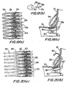
- FIGS . 19(a), 19(b) and 19(c) illustrate an alternative embodiment in accordance with the subject invention.
- connector 10e is provided with two sets of substantially.”U"-shaped fingers, radial expansion members, or radial expansion members 82e and outer opposition fingers 84e.
- Each radial expansion member 82e is positioned with respect to an adjacent outer opposition finger 84e such that their respective end portions are joined at common locations, which form' internal opposition fingers 86e, spaced apart by spacing 87e.
- This spacing 87e in conjunction with the resilient characteristics of the material, permits the connector 10e to radially expand and contract, as will be described in greater detail below.
- radial expansion members 82e are smaller than outer opposition fingers 84e, although it is contemplated that radial expansion members 82e may be the same size or larger than outer opposition fingers 84e.
- engagement member 88e At the vertex of each radial expansion member 82e is an engagement member 88e, which is configured to secure the graft conduit to the connector 10e.
- engagement member 88e has a sharpened tip 89e for piercing the tissue of the graft conduit. The pierced tissue is subsequently advanced past the tip 89e to a narrower neck portion 90e, positioned between shoulder portions 91e and 92e.
- the shoulder portions 91e and 92e prevent the tissue from slipping with respect to the engagement member 88e.
- Shoulder portion 92e inhibits the tissue from sliding off of engagement member 88e, whereas shoulder portion 91e inhibits the engagement member 88e from penetrating the tissue too deeply.
- connector 10e is formed such that outer opposition fingers 84e and internal opposition fingers 86e extend radially outward to form a-substantially "U"-shaped configuration. Engagement members 88e are oriented radially outward.
- Connector 10e is installed with respect to conduit 90 and graft conduit 30 in a substantially similar manner to connector 10, as described with respect to FIGS. 10- . 14 , above.
- connector 10e may be mounted in a substantially similar manner, such that connector 10e is radially compressed when it is fitted over intermediate sleeve 56.
- Each radial expansion member 82e is positioned coaxially within outer sleeve 58, and each internal opposition finger 86e is held beneath collar 68 of distal tip portion 54.
- Graft conduit 30 is positioned over connector 10e such that engagement members 88e pierce the graft conduit and secure the graft tissue in the neck portion 90e of each engagement member 88e ( FIG. 19(b) ).
- connector 10e is mounted in a substantially similar manner, such that each outer opposition finger 84e is deflected proximally and maintained in position by sheath 64.
- connector 10e When connector 10e is installed in body conduit 90 as shown in FIG. 19(c) , connector 10e is permitted to return to a radially expanded configuration. Radial expansion members 82e contact and support graft conduit 30, which is secured by engagement members 88e. The end portion of graft conduit 30 is also positioned between radial expansion members 82e and outer opposition fingers 84e to provide a trumpet-shaped, or flared configuration. The wall of body conduit 90 is engaged by outer opposition fingers 84e and internal opposition fingers 86e, which have assumed an angled, substantially "U"-shaped configuration. This configuration, as described above, improves fluid flow and graft patency.
- FIGS. 20(a) and 20(b) illustrate an alternative embodiment of the connector.
- Connector 10f is substantially similar to connector 10e.
- connector 10f is also provided with radiused portion 85f, which extends from outer opposition member 84f.
- radiused portion 85f is formed with a curvature reversed from that given to outer opposition member 84f.
- the radiused portions 85f assist the surgeon in delivering and positioning the connector 10f by providing an atraumatic engagement structure for engaging a delivery system or existing body tubing, as will be described in greater detail below.
- portion 85f could be configured with any atraumatic surface, such as a beaded tip , which inhibits damage to existing body tubing during deployment.
- Connector 10g is provided with a band portion 80g, including a plurality of loops 82g connected at respective corners, each loop 82g defining an aperture 84g.
- a plurality of fingers is provided on both distal and proximal end portions of band 80g.
- Internal opposition fingers 86g extend from the distal side of each of alternating loops 82g.
- External opposition fingers 88g extend from the proximal side of the same loop 82g as fingers 869.
- connector 10g is formed such that internal opposition fingers 86g and external opposition fingers 88g assume a "U"-shaped configuration to engage the wall of body conduit 90.
- the "U"-shaped configuration of fingers 86g and 88g may be formed such that the conduit tissue assumes a radially flared bell-shaped configuration.
- fingers 86'g and 88'g may be given a "U"-shaped configuration which is symmetrical on both sides of the wall of conduit 90, as shown in FIG. 21(c) .
- each of the embodiments of the subject invention may incorporate the symmetrical "U"-shaped configuration as well.
- Connector 10h is provided with a band portion 80h having a plurality of loops 82h joined at their respective corners and defining apertures 84h therein.
- a plurality of fingers are provided on the distal portion of the loops. Both internal opposition fingers 86h and external opposition fingers 88h extend from the distal portion of the loops 82h.
- a shoulder portion, or barb 89, extends laterally from internal opposition finger 86h to secure the graft, as will be described below.
- the graft 30 is placed inside formed connector 10h.
- Connector 10h is installed substantially as for connector 10g.
- FIGS. 23(a) and 23(b) illustrate another embodiment.
- connector 10i is provided with a band section 80i including a plurality of loops 82i joined at respective corners and defining apertures 84i therein.
- Internal opposition fingers 86i and external opposition fingers 88i are substantially "U" shaped and have a pair of end portions. Internal opposition fingers 86i extend from the distal side of band section 80i. Likewise, external opposition fingers 88i extend from the proximal side of band section 80i.
- FIG. 23(b) illustrates the graft positioned inside connector 10i. The connector 10i is formed such that internal opposition fingers 88i form a flared configuration.
- the end portion of the graft is substantially expanded to assume this flared configuration and maintained in position by everting the end portion over the internal opposition fingers 86i without necessarily piercing the graft material or tissue.
- opposition fingers 86i may be provided with atraumatic tips.
- Internal 86i and external opposition fingers 88i are formed in the "U"-shaped configuration to grip the tissue of the body conduit 90 therebetween.
- the connectors described above, particularly connector 10f ( FIGS. 20(a) and 20(b) ), are also suited for installation in the patient through percutaneous installation without the necessity to make surgical incisions in the patient near the operative site.
- Percutaneously deployed apparatus may be inserted into the lumen of a body conduit at a remote entry location and advanced intraluminally within the patient to the anastomosis site. Such percutaneous procedures are disclosed in commonly-assigned U.S. Patent 5,976,178 .
- Apparatus for percutaneous installation of connector 10f is illustrated in FIG. 24 , and denoted by reference number 250.
- Apparatus 250 may include an inner rod 252 (alternatively, an inner sleeve or sheath may be used), outer sleeve 258, and catheter or sheath 264.
- Inner rod or sheath 252, which has a distal tip 254, is substantially similar to inner rod 52 and distal tip 54, described above.
- Distal tip 254 has a circumferential flange, or collar 268, defining an annular space 270 between inner rod 252 and flange 268.
- An outer sleeve 258 is coaxially positioned around inner rod 252.
- Sheath 264 surrounds the entire assembly.
- Apparatus 250 is particularly suitable for percutaneous installation of connector 10f.
- FIG. 25 illustrates apparatus 250 with connector 10f and graft conduit 130 in position within the lumen of existing body conduit 90.
- Apparatus 250 may be adapted for insertion within and passage along a catheter or other tube. Consequently, the constituent components are preferably flexible.
- a catheter, or sheath 264 may be positioned partially within body conduit 90. The distal end 265 of catheter 264 extends outwardly through an aperture in the wall of conduit 90 and serves as an access port from the inside of conduit 90 to the outside surrounding operative region.
- Connector 10f is positioned at the distal end portion of apparatus 250.
- the various fingers are retained in a configuration substantially parallel with longitudinal axis of apparatus 250.
- Graft conduit 130 is connected to connector 10f as will be described below.
- Apparatus 250, along with connector 10f and graft conduit 130, is passed into and along the lumen of body conduit 90 from an access point which may be remote from the anastomosis site.
- connector 10f is mounted in apparatus 250.
- connector 10f is oriented in the opposite direction in FIGS. 25-31 , compared with FIGS. 20(a)-20(b) , above.
- the distalmost portion is represented in the same direction in these FIGS.
- fingers 86f are the distalmost portions of connector 10f ( FIGS. 20(a) -20(b) ), i.e., they are furthest from the physician.
- fingers 82f are distalmost.
- Inner rod or inner sheath 252 may have an outer diameter smaller than the nominal diameter of connector 10f.
- Connector 10f is fitted around inner rod or inner sheath 252 and radially compressed. Fingers 82f are fitted underneath circumferential flange 268 of distal tip portion 254 and deflected towards parallelism with the longitudinal axis to a flattened distally-extending configuration. Likewise, internal opposition fingers 86f are flattened to a proximally-extending configuration also towards parallelism with the longitudinal.axis. Internal opposition fingers 86f are retained in this configuration by outer sleeve 258. Engagement members 88f extend radially outward and engage the graft conduit 130 which is positioned at the distal end portion of inner rod 25.2 and distal tip 254. Engagement members 88f may alternatively be similar to engagement members 88e (See, FIGS.
- Catheter 264 is positioned over connector 10f and graft conduit 130, such that the external opposition fingers 84f are deflected to a proximally facing configuration toward parallelism with the longitudinal axis and maintained in this configuration by sheath 264.
- the configuration illustrated in FIG. 26 is advantageous for passage into and along a body conduit at the operative site. The retraction of the external opposition fingers 84f and 85f within catheter 264 and the atraumatic distal tip 254 minimize the possibility of injuring adjacent tissue.
- Apparatus 250 is advanced along body conduit 90 until connector 10f is positioned just outside the body conduit 90 as shown, with radiused finger portions 85f outside the wall of conduit 90.
- catheter 264 is withdrawn proximally into conduit 90 until it clears the radiused end portions 85f of external opposition fingers 84f.
- Connector 10f has been formed such that external opposition fingers 84f are normally biased to a first angle as illustrated in FIG. 27 , which is approximately 20°-30° from the longitudinal axis.
- the fingers 84f resiliently move to the first angle shown.
- the radiused end portions 85f may be initially a small distance 257 from the outer surface of body conduit 90, due to the pivoting motion of fingers 84f.
- the apparatus 250 along with connector 10f is retracted proximally into conduit 90 until the radiused portions 85f contact the outer surface of conduit 90, as illustrated in the dotted line configuration of FIG. 28 . Further proximal movement of apparatus 250 results in contact of radiused portions 85f against the outer wall of conduit 90.
- the shape of radiused portion 85f acts as a camming surface, such that axial movement of connector 10f with respect to conduit 90 causes radiused portion 85f to atraumatically ride over the outer wall of conduit 90 and thereby cam external opposition fingers 84f to a second angle illustrated in solid lines.
- Outer sleeve 258 is retracted proximally until it clears the internal opposition fingers 86f of connector 10f, as illustrated in FIG. 29 .
- Internal opposition fingers 86f expand outwardly from the slightly flattened configuration (illustrated in dashed lines) to a curved, radial configuration in order to engage the inner surface of the wall of the conduit 90.
- retraction of outer sleeve 258 is performed while tension is applied on inner rod or sheath 2 52 in order to maintain connector 10f and external opposition fingers 84f in an upright, secure position with respect to the wall of conduit 90.
- Inner rod 252 is advanced distally such that circumferential flange 268 clears the end portions of radial expansion members 82f ( FIG. 30 ). As the distal tip portion 254 moves distally beyond radial expansion members 82f, the members expand or flare radially outwardly from the flattened configuration (as indicated by the arrows) and thereby partially expand the end portion of graft conduit 130. Such expansion of members 82f improves fluid flow between body conduit 90 and graft conduit 130. Simultaneously, connector 10f expands in diameter in order to provide a secure fluid seal between the conduit 90 and graft conduit 130. Inner rod 252 and outer sleeve 258 may be removed from the anastomosis site. As illustrated in FIG. 31 , the connector 10f expands sufficiently so that distal tip 254 may pass inside connector and be withdrawn proximally.
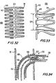
- connector 100 An alternative embodiment of a percutaneously deployed connector is connector 100, which is formed from a tube of material substantially as described above with respect to FIG. 2 .
- component 100 is provided with a plurality of internal support struts 114 and internal opposition fingers 118. Outer opposing fingers are omitted in this particular embodiment, although it is contemplated that such fingers may be useful in accordance with this invention.
- Radial expansion members 114 are formed with a flared configuration extending axially and radially outward for engaging the interior of the graft conduit, as will be described below.
- Internal opposition fingers 118 are oriented substantially radially outward.
- a plurality of engagement members 116 are provided between adjacent fingers to secure the graft conduit.
- the planar representation of the machined section of FIG. 32 is an exemplary embodiment, and other configurations are contemplated within the scope of this invention.
- the connector 100 is given a nominal internal diameter 124.
- the resilient characteristics of the material and the apertures 120 permit the diameter 124 to be compressed and expanded during mounting and installation.
- FIG. 34 illustrates an apparatus 150 particularly suitable for percutaneous installation of connector 100. Similar to apparatus 250 described above ( FIG. 24 ), apparatus 150 may be adapted for insertion within and passage along a catheter or other tube. As illustrated in the FIG., catheter 190 may be positioned partially within body conduit 90, with the distal end 192 of catheter 190 extending outwardly through an aperture in the wall of conduit 90 and serving as an access port from the inside of conduit 90 to the outside surrounding operative region. The distal end of inner rod 152 is provided with a distal tip portion 154, substantially similar to distal tip 254 ( FIG. 24 ). Graft conduit 130 is connected to connector 100 as will be described below. Apparatus 150 retains fingers of component 100 in a substantially parallel configuration.
- inner rod 152 has an outer diameter smaller than the nominal diameter 124 of connector 100 (See, FIG. 33 ).
- Connector 100 is fitted around inner rod 152 and compressed.
- Fingers 114 are fitted underneath circumferential flange 168 of distal tip portion 154 and deflected towards parallelism with the longitudinal axis to a flattened distally-extending configuration.
- internal opposition fingers 118 are slightly flattened to a proximally-extending configuration also toward parallelism with the longitudinal axis.
- Engagement members 116 extend radially outward and engage the graft conduit 130 which is positioned at the distal end portion of inner rod 152.
- Engagement members may alternatively be similar to engagement members 88e (See, FIGS.
- FIGS. 34-36 illustrate, it is contemplated that the procedure according to the invention may be conducted through an aperture in conduit 90 without the use of a catheter 190.
- Apparatus 150 is advanced along body conduit 90 until connector 100 is positioned at the aperture of body conduit 90 as shown, with radial expansion members 114 extending outside conduit 90 and internal opposition fingers 118 positioned within conduit 90.
- Inner rod 152 is advanced distally such that circumferential flange 168 clears the end portions of radial expansion members 114 ( FIG. 36 ).
- Connector 100 is maintained stationary while outer sleeve 158 is withdrawn proximally. If an introduction catheter 190 is used, such catheter may be withdrawn proximally with outer sleeve 158.
- the struts expand or flare radially outwardly from the flattened configuration (illustrated in dashed lines) and thereby expand the end portion of graft conduit 130.
- Such expansion of struts 114 minimizes the likelihood of graft conduit 130 moving out of position and back into conduit 90 during and after installation, and improves fluid flow between body conduit 90 and graft conduit 130.
- Outer sleeve 158 is further retracted proximally until it clears the internal opposition fingers 118 of connector 100, as illustrated in FIG. 37 .
- Internal opposition fingers 118 expand outwardly from the slightly flattened configuration (illustrated in dashed lines) to a curved, radial configuration in order to engage the inner surface of the wall of the conduit 90.
- connector 100 expands in diameter in order to provide a secure fluid seal between the conduit 90 and graft conduit 130.
- Inner rod 152 and outer sleeve 158 may be removed from the anastomosis site. The connector 100 expands sufficiently that distal tip 154 may pass inside connector and be withdrawn proximally.
- apparatus 250 may be deployed from the lumen of a catheter 290 or other tube which has passed through an aperture in body conduit 90 from internally to the outside of the conduit. (It is also contemplated that apparatus may be deployed from an aperture in a body conduit without the use of a separate catheter.)
- connector 100 Prior to deploying apparatus 250, connector 100 is mounted in the apparatus ( FIG. 38 ). As shown in FIG. 33 , connector 100 has a nominal internal diameter 124 which is larger than the outer diameter of both inner rod 252 and distal tip 254. Connector 100 is passed over distal tip 254, and the resilient characteristics described above permit the connector 100 to be compressed to a smaller diameter around inner rod 252.
- the struts 114 are compressed from the flared configuration of FIG. 33 toward parallelism with the longitudinal axis to a substantially distal flattened configuration and maintained in such configuration by collar 268.
- the internal opposition fingers 118 are deflected toward parallelism with the longitudinal axis and maintained in a substantially flattened, proximally-extending configuration between inner rod 252 and outer sleeve 258.
- Engagement members 116 which extend radially outward, engage the graft conduit 230.
- Sheath 264 coaxially surrounds apparatus 250 and graft conduit 230.
- apparatus 250 is advanced until radial expansion members 114 are disposed beyond the wall of conduit 90.
- inner rod 252 along with distal tip 254 are moved distally, while outer sleeve 258 remains stationary.
- collar 268 is advanced beyond the distalmost end of connector 100, struts 114 are permitted to move from their straightened configuration (illustrated in dashed lines) to a radially flared position engaging the inner surface of graft conduit 230.
- Catheter 290 and sheath 264 are maintained stationary, so that struts 114 and graft conduit 230 are constrained within the lumen of sheath 264.
- catheter 290 and sheath 264 are withdrawn proximally into conduit 90, permitting the side walls of conduit 90 to close around graft 230, which is exposed from sheath 264.
- Struts 114 are permitted to move from the slightly deflected configuration of FIG. 39 (illustrated in dashed lines) to a radially flared position engaging the inner surface of graft conduit 230.
- Graft conduit 230 is expanded in overall diameter, which assists in preventing graft conduit 230 from moving proximally back into conduit 90.
- Outer sleeve 258 is subsequently withdrawn proximally with respect to inner rod 252 ( FIG. 41 ).
- internal opposition fingers 11B move from the flattened configuration (illustrated in dashed lines) to the curved configuration to engage the inner surface of the conduit wall.
- the diameter of connector 100 expands to a larger diameter as indicated by the arrows. This provides a seal between the graft 230 and conduit 90.
- the increased internal, diameter permits the distal tip 254 to be withdrawn proximally through connector 100 (not shown).
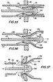
- FIGS.42-46 illustrate a further embodiment.
- Tool 500 is provided to facilitate the mounting of a connector onto an end portion of the graft conduit 30.
- Tool 500 is sized and configured to provide a flared, or everted edge to the graft conduit.
- This flared configuration of the graft assists in the connection with the tubular body structure by facilitating blood flow from the graft conduit to the body conduit.
- this configuration helps to seal the opening in the body conduit into which the graft is inserted and accommodates size variations between the graft and the opening.
- the graft conduit is a natural blood vessel, e.g., the saphenous vein, this configuration permits the blood to remain in contact with endothelium tissue during the transition between the graft and the body conduit.
- eversion tool 500 has a tubular body portion 502 sized and configured for insertion into the graft conduit in the axial direction 506, and a larger flange portion 508 which remains outside the graft conduit.
- a plurality of apertures 512 are defined in flange portion 508, and extend axially within flange portion 508. (See, FIG. 43 .)
- Eversion tool 500 is inserted into the end portion of graft conduit 30 ( FIG. 42 ).
- Tubular portion 502 is advanced within the graft conduit until the end of graft conduit abuts flange portion 508, which has a surface disposed at approximately a right angle with respect to tubular portion 502. Further axial advancement of tool 500 with respect to graft conduit will cause the end portion of the graft to flare outwardly against the flange portion to create flange 530. As shown in the FIG., advancement of tool 500 results in the eversion of graft conduit.
- FIG. 44 illustrates the installation of a connector 550 to the graft conduit 30.
- Connector 550 may assume a number of different configurations.
- connector 550 includes a medial band portion 552.
- a plurality of fingers 554 and 556 are provided on both axial end portions of the band portion 552.
- fingers 554 and 556 are fabricated of a resilient material and assume a radially outward or "U"-shaped configuration when viewed from a plane extending radially out from the tubular portion in the relaxed or unstressed configuration (see, FIG. 45 ). Fingers 554 and 556 assume a flattened axial configuration substantially parallel with axis 506 when in the stressed configuration.
- the connector 550 is positioned coaxially surrounding the graft conduit 30.
- a deployment sheath 560 is positioned in a coaxially surrounding configuration around connector 550 and graft conduit 30. This placement of the sheath 560 deflects fingers 554 and 556 toward parallelism with axis 506, such that internal opposition fingers 554 are deflected distally and external opposition fingers 556 are deflected proximally.
- connector 550 is advanced distally toward flange 508.
- the internal opposition fingers 554 are advanced to pierce the flange 530 of the graft conduit 30 and pass into the apertures 512 defined in the flange 508.
- deployment sheath 560 and eversion tool 500 are removed from the graft conduit 30.
- Internal 554 and external opposition fingers 556 of connector 550 return to their unstressed configuration.
- Connector 550 and graft conduit 30 may be mounted within an outer sleeve, such as sleeve 58 of FIGS. 8-13 .
- Internal 554 and external opposition fingers 556 are maintained in a flattened configuration similar to that shown in FIG. 44 .
- the sleeve 58 is withdrawn, and fingers return to their unstressed configuration as illustrated in FIG. 46 .
Abstract
Description
- This invention relates to structures that can be used to make connections between tubular medical grafts and a patient's tubular body conduits. The invention also relates to methods for making and using the structures mentioned above.
- Tubular grafts are frequently needed in medical procedures. For example, a coronary bypass procedure may involve the installation of a tubular graft between an aperture that has been formed in the side wall of the aorta and an aperture that has been formed in the side wall of a coronary artery downstream from an occlusion or blockage in that artery. Each end of the graft must be connected to the side wall of either the aorta or the coronary artery. Each such connection must extend annularly around the associated end of the graft conduit and be fluid-tight so that no blood will leak out. One common way to produce such connections is by suturing. It will be appreciated, however, that making such connections by suturing can be extremely difficult, time-consuming, and dependent on the skill of the physician for the quality of the results. There is also increasing interest in less invasive procedures which tend to impose constraints on the physician's access to the sites at which graft connections must be made and thereby make it more difficult or even impossible to use suturing to make such connections (see, for example,
Goldsteen et al. U.S. Patent 5,976,178 , Sullivan et al. and publishedPCT patent application WO 98/55027 - Various types of mechanical connectors have been developed to reduce or eliminate the need for suturing; but improvements are constantly sought for such mechanical connectors with respect to considerations such as ease and speed of use, ease of manufacture, strength and permanence of the resulting connection, etc. A connector, including methods for making and installation thereof, is disclosed in
published PCT patent application WO 99/38454 - In view of the foregoing, it is an object of this invention to provide improved and simplified graft connectors for connecting two tubular structures without the use of sutures.
- It is still another object of this invention to provide improved and simplified methods of making structures that can be used as medical graft connectors.
- These and other objects of the invention are accomplished in accordance with the principles of the invention by providing a connector which may be attached to two tubular structures without the use of sutures or other attachment means. The connector is preferably formed by using a highly elastic material such as nickel and titanium alloy (nitinol) metal. A first plurality of fingers is configured to engage an interior surface of the side wall of the existing conduit. A second plurality of fingers is configured to engage an exterior surface of the side wall of the existing conduit. A third plurality of fingers is received in an interior lumen of the graft conduit, and a fourth plurality of fingers is configured to pierce the graft conduit. The connector is radially deformable between a first size and a second size.
- In a preferred embodiment, the first, second and fourth pluralities of fingers are substantially radially aligned with respect to a longitudinal axis of the connector. The first and second pluralities of fingers may be resiliently deformable towards parallelism with the longitudinal axis of the connector. A substantially "U"-shaped configuration may be defined by adjacent, ones of the first and second plurality of fingers when viewed from a plane extending radially out from the longitudinal axis of the connector.
- To install the graft connector in a patient, a tubular graft conduit is attached to the connector. The first and second pluralities of fingers of the connector may be deflected inwardly toward parallelism with the longitudinal axis. The connector and graft conduit may be inserted in a delivery apparatus, which may maintain the fingers in their substantially axially extending condition. The delivery apparatus may then be inserted through the aperture in the side wall of the patient's tubular body conduit to which the end of the graft conduit is to be attached. The delivery apparatus is manipulated such that restraint is removed from the fingers of the connector. This permits the fingers to spring out to engage the tissue structure to which the connection is to be made. The delivery may be performed by passing the delivery structure intraluminally within the patient's tubular body conduit and through the wall of the body conduit to outside the conduit.
- Further features of the invention, its nature and various advantages will be more apparent from the accompanying drawings and the following detailed description of the preferred embodiments.
-
FIG. 1 is a perspective view of an illustrative embodiment of a component of this invention. -
FIG. 2 is a simplified planar representation of the component ofFIG. 1 . -
FIG. 3 is a side view in partial cross-section of theFIG. 1 component taken through lines 3-3 ofFIG. 1 . -
FIG. 4 is a simplified elevational view of a graft conduit, during a first stage of processing the body conduit. -
FIG. 5 is a view similar toFIG. 4 , illustrating a subsequent stage of processing. -
FIG. 6 is a view similar toFIG. 5 , illustrating a further stage in such processing. -
FIG. 7 is a simplified elevational view, illustrating the body conduit after the processing ofFIGS. 4-6 . -
FIG. 8 is a perspective view of apparatus according to the invention which is suitable for installing the component ofFIG. 1 . -
FIG. 8(a) is a partial perspective view, similar toFIG. 8 , of an alternative embodiment of apparatus suitable for installing the component ofFIG. 1 . -
FIG. 9 is a simplified sectional view of the component ofFIG. 8 , taken along lines 9-9 ofFIG. 8 . -
FIG. 10 illustrates theFIG. 9 apparatus with a graft conduit added so that theFIG. 1 component can be used as a connector for the graft conduit. -
FIG. 11 is a simplified sectional view of theFIG. 9 apparatus with another component added to facilitate insertion in the patient. -
FIG. 12 is a simplified sectional view of theFIG. 11 apparatus, illustrating a stage in the installation of theFIG. 1 component in a patient. -
FIG. 13 . is a view similar toFIG. 12 , illustrating a further stage in the installation of theFIG. 1 component. -
FIG. 14 is an enlarged view similar toFIG. 13 , illustrating another further stage in the installation of theFIG. 1 component. -
FIG. 15(a) is a planar representation similar toFIG. 2 , illustrating another embodiment of the component ofFIGS. 1-3 . -
FIG. 15(b) is a side view in partial cross-section similar toFIG. 14 , illustrating the component ofFIG. 15(a) after processing and installation in the patient. -
FIG. 16(a) is a planar representation similar toFIG. 2 , illustrating another embodiment of the component ofFIGS. 1-3 . -
FIG. 16(b) is a side view in partial cross-section similar toFIG. 14 , illustrating the component ofFIG. 16(a) after processing and installation in the patient. -
FIG. 17(a) is a planar representation similar toFIG. 2 , illustrating another embodiment of the component ofFIGS. 1-3 . -
FIG. 17(b) is a side view in partial cross-section similar toFIG. 14 , illustrating the component ofFIG. 17(a) after processing and installation in the patient. -
FIG. 18(a) is a planar representation similar toFIG. 2 , illustrating another embodiment of the component ofFIGS. 1-3 . -
FIG. 18(b) is a side view in partial cross-section similar toFIG. 14 , illustrating the component ofFIG. 18(a) after processing and installation in the patient. -
FIG. 19(a) is a planar representation similar toFIG. 2 , illustrating another embodiment of the component ofFIGS. 1-3 . -
FIG. 19(b) is an enlarged view of a portion of the component ofFIG. 19 (a) . -
FIG. 19(c) is a side view in partial cross-section similar toFIG. 14 , illustrating the component ofFIG. 19(a) after processing and installation in the patient. -
FIG. 20(a) is a planar representation similar toFIG. 2 , illustrating another embodiment of the component ofFIGS. 1-3 . -
FIG. 20(b) is a side view in partial cross-section similar toFIG. 14 , illustrating the component ofFIG. 20(a) after processing and installation in the patient. -
FIG. 21(a) is a planar representation similar toFIG. 2 , illustrating another embodiment of the component ofFIGS. 1-3 . -
FIG. 21(b) is a side view in partial cross-section similar toFIG. 14 , illustrating the component ofFIG. 21(a) after processing and installation in the patient. -
FIG. 21(c) is a side view similar toFIG. 21(b) , illustrating an alternative embodiment. -
FIG. 22(a) is a planar representation similar toFIG. 2 , illustrating another embodiment of the component ofFIGS. 1-3 . -
FIG. 22(b) is a side view in partial cross-section similar toFIG. 14 , illustrating the component ofFIG. 22(a) after processing and installation in the patient. -
FIG. 23(a) is a planar representation similar toFIG. 2 , illustrating another embodiment of the component ofFIGS. 1-3 . -
FIG. 23(b) is a side view in partial cross-section similar toFIG. 14 , illustrating the component ofFIG. 23(a) after processing and installation in the patient. -
FIG. 24 is cross-sectional view of an apparatus for installing the component ofFIGS. 20(a)-20 (b ). -
FIG. 25 is a simplified schematic sectional view, illustrating a stage in the installation of the component ofFIGS. 20(a)-20(b) . -
FIG. 26 is an enlarged sectional view, similar toFIG. 25 . -
FIG. 27 is an enlarged sectional view, similar toFIG. 26 , illustrating a later stage in the installation of the component ofFIGS. 20(a)-20(b) . -
FIG. 28 is an enlarged sectional view, similar toFIG. 27 , illustrating yet a later stage in the installation of the component ofFIGS. 20(a)-20(b) . -
FIG. 29 is an enlarged sectional view, similar toFIG. 28 , illustrating a further later stage in the installation of the component ofFIGS. 20(a)-20 (b) . -
FIG. 30 is an enlarged sectional view, similar toFIG. 29 , illustrating another later stage in the installation of the component ofFIGS. 20(a)-20(b) . -
FIG. 31 is an enlarged sectional view, similar toFIG. 30 , illustrating withdrawal of theFIG. 24 apparatus from the operative site. -
FIG. 32 is a planar representation similar toFIG. 17(a) , illustrating another embodiment of the component ofFIGS. 1-3 . -
FIG. 33 is a side view in partial cross-section similar toFIG. 14 , illustrating the component ofFIG. 32 after processing. -
FIG. 34 is a simplified schematic sectional view, illustrating a stage in the installation of the component ofFIG. 32 . -
FIG. 35 is an enlarged sectional view, similar toFIG. 34 . -
FIG. 36 is an enlarged sectional view, similar toFIG. 35 , illustrating a later stage in the installation of the component ofFIG. 32 . -
FIG. 37 is an enlarged sectional view, similar toFIG. 36 , illustrating yet a later stage in the installation of the component ofFIG. 32 . -
FIG. 38 is a simplified sectional view of the component ofFIG. 32 and a graft conduit mounted in theFIG. 24 apparatus, illustrating a stage in the installation of theFIG. 32 component in the patient. -
FIG. 39 is a simplified sectional view similar toFIG. 38 , illustrating a further stage in the installation. -
FIG. 40 is a simplified sectional view similar toFIG. 39 , illustrating another stage in the installation. -
FIG. 41 is a simplified sectional view similar toFIG. 40 , illustrating yet another stage in the installation. -
FIG. 42 is a simplified sectional view of a graft conduit, and an apparatus for installing a component on the graft conduit. -
FIG. 43 is a simplified elevational view of the apparatus ofFIG. 42 . -
FIG. 44 is a sectional view similar toFIG. 42 , illustrating a stage in the installation of a component on the graft conduit. -
FIG. 45 is a view similar toFIG. 44 , illustrating a component in accordance with the invention installed in the graft conduit. -
FIG. 46 is a simplified perspective view in partial cross-section, illustrating the graft conduit and component ofFIGS. 42-43 installed in the tubular body conduit. -
FIG. 1 illustrates a preferred embodiment of aconnector 10 for use in connecting an end portion of a tubular graft conduit to a side wall of a patient's tubular body conduit. In order to facilitate the end-to-side anastomosis of two tubular body conduits,connector 10 is formed with a substantially radial configuration having a band portion 11 defining acentral aperture 12 about which a plurality of components, or fingers, are oriented radially and axially outward from the band portion. The band 11 is configured for coaxial mounting with respect to the end portion of a graft conduit, and the fingers are configured to engage the side wall of a tubular body conduit through an aperture in that side wall. In the preferred embodiment, the band 11 is composed of a plurality ofinternal struts 14. The internal struts 14 are configured to engage one side of the wall of a graft conduit.Engagement members 16 extend radially outward and assist to secure the graft conduit to theconnector 10, as will be described in greater detail below. A plurality ofinternal opposition fingers 18 are positioned adjacent a plurality ofexternal opposition fingers 20 and extend radially and axially outward from an end portion of the band 11. The internal 18 andexternal fingers 20 are configured to engage both the inside and the outside wall of a second tubular conduit, typically a body conduit. As described in greater detail below,connector 10 is preferably fabricated from a single piece of material as a single, integral unit. -
FIG. 2 illustrates a planar representation of the connector of this invention shown inFIGS. 1 and 3 .Component 10 may be formed from a sheet of material, which is preferably highly elastic. A particularly preferred material is nickel titanium alloy (nitinol) metal, but other materials such as stainless steel or thermoplastics may be used instead if desired. The starting sheet may have any length, diameter, and wall thickness suitable for the intended use of the finished connector. For example, the thickness of the sheet and the length of the struts and opposition fingers may be determined by the size of the body conduits joined or the pressure of fluids passing therethrough. For use as a cardiac bypass graft connector, for example, band 11 may have anominal diameter 24 of about 4.0 millimeters, a wall thickness of about 0.08 millimeters (0.003 inches), and a length of about 7.0 millimeters. It will be understood, however, that these specific dimensions are only exemplary, and that any other dimensions can be used instead if desired. - A first step in
manufacturing component 10 in accordance with the invention is to form the sheet into a cylindrical tube. The next step involves cutting or machining the tube. The following cutting steps may be performed simultaneously, or in any order deemed appropriate by one skilled in the art. The axial end portions of the' sheet are substantially axially cut to provide a plurality of fingers. Substantially axial "U"-shaped cuts may be made at spaced intervals in order to provide a separation between the fingers. In this embodiment, theinternal opposition fingers 18 andengagement members 16 are formed by such cutting and extend substantially axially from the band portion 11. As will be described below,internal opposition fingers 18 andengagement members 16 define the distal portion of the connector. - A second set of fingers is cut from the band portion 11, i.e., a medial portion of the sheet, or tube. More particularly, a series of substantially axial "U"-shaped cuts are made in the sheet to define
external opposition fingers 20. Each "U"-shaped cut includes two elongated axial cuts which may extend from one axial end portion of the sheet to the other end portion, and a shorter transverse cut adjacent one end portion of the sheet to provide the "U" configuration. (The cut may remove material from the sheet, as shown in the FIG.) Theexternal opposition finger 20 thus defined has anend portion 23 integral with aninternal opposition finger 18.Fingers 20 are substantially longer thanfingers 18 in order to be partially coextensive with fingers 18 (seeFIG. 3 ) and to provide contact surfaces with both the graft conduit and the body conduit, as will be described below. Eachexternal opposition finger 20 is "U"-shaped in the plan view due to amedial aperture 22 defined in the center of each of thefingers 20. - Thus, a portion of the band 11 is removed by the formation of the
external opposition fingers 20. Further material is removed from the band 11 by a series of substantially axial cuts to createinternal struts 14 at the opposite axial end from the cuts made to formfingers struts 14 andintermediate strap portions 19 defined between each set ofinternal struts 14. The combination of the resiliency of the component material, axial cuts, "U"-shaped cuts, andapertures 22 allows radial contraction and expansion of thediameter 24 of band 11, and therefore ofcomponent 10, during delivery and deployment, as will be described in greater detail below. - The starting tube is machined into the configuration (represented as a plane in
FIG. 2 ) by laser cutting, electron discharge machining (EDM), or etching. The machining may be performed either in the cylindrical tubular configuration or in the sheet configuration, depending upon the requirements of the materials and machining methods. Material not shown inFIG. 2 is subsequently removed from the starting sheet to provide the geometry shown in the FIG. - The next step is to deflect fingers on the machined tube to approximately the positions that are desired in the finished and installed connector. For example,
FIG. 3 showsresilient fingers component 10 will assume after deployment. It will be appreciated that it may be desirable to deflectfingers component 10 from the mold due to the properties of the NiTi material. The connector can be cooled to improve malleability to aid in positioning into the mold or during delivery. As can be clearly seen in the FIG., adjacent ones offingers angle 19 less than a right angle with the axis 11 (typically 20°-90°), as will be described in greater detail below.Connector 10 defines anominal diameter 24. It is contemplated thatnominal diameter 24 is selected to be marginally greater than the internal diameter of the graft conduit, such that theinternal struts 14 bear on the interior of graft when they are positioned inside the graft.Apertures 22, as well as the resilient material selected for theconnector 10, permit the expansion and reduction of the diameter from thenominal diameter 24. -
Connector 10, subsequent to formation, above, is used to join a graft conduit and a tubular body conduit in an end-to-side anastomosis. The graft conduit may be a natural conduit (e.g., a relocated portion of the patient's tubular body tissue), an artificial conduit (e.g., of the type shown in above-mentionedU.S. Patent 5,976,178 ), or a composite of natural and artificial conduits. -
FIGS. 4-7 show apparatus and methods to prepare, and in some cases, remove a body conduit for use as the graft conduit.FIG. 4 illustratesconduit 30 disposed within the body and typically serving as a conduit for fluid, e.g., blood. Theconduit 30 has a plurality ofside branches 32 for transporting fluid between theconduit 30 and the surroundingtissue 34. In an exemplary embodiment, theconduit 30 is an external jugular vein. A portion of the conduit is exposed. In this embodiment, approximately 15 cm of the vein is exposed. A first, orcranial location 36 is selected. A second, orcaudal location 38 is likewise selected. The first 36 andsecond locations 38 are spaced apart by alength 39, e.g. 12 cm for use as a graft conduit in coronary artery bypass. Thegraft conduit 30 is ligated, clipped, or otherwise closed at the first 36 andsecond locations 38. Theside branches 32 protruding from the vein body are subsequently ligated and cut. - As illustrated in
FIG. 5 , anintroducer 40, having adiameter 42 of approximately 3 French, is inserted into thegraft conduit 30 at apoint 44 slightly distal of thefirst location 36. Theintroducer 40 is advanced distally to a position adjacent thesecond location 38. An end portion of theintroducer 40 remains outside thegraft conduit 30. - The
conduit 30 is provided with afirst cut 46 defining an oblique angle of approximately 45° with respect to the conduit axis adjacent the second location 38 (FIG. 6 ). It is contemplated that this procedure may be used for a conduit which is not entirely removed from its original location. For example, the internal mammary artery (IMA) is used as a blood source in coronary artery bypass procedures by cutting one end of the IMA and connecting that end to the coronary artery downstream of an occlusion by end-to-side anastomosis. Asecond cut 47 is made at approximately a 90° angle with respect to the axis adjacent thefirst location 36. This second cut 47 passes through both thegraft 30 andintroducer 40. The cut portion of theintroducer 40 outside thegraft conduit 30 is discarded. Thegraft 30 andintroducer 40 are removed such that theintroducer 40 remains within the graft 30 (FIG. 7 ), and bothgraft 30 andintroducer 40 are placed in an appropriate solution. Thegraft 30 is to be used for connection to the side wall of the tubular body conduit. -
Connector 10 may be installed to join two tubular conduits using several techniques. Anexemplary apparatus 50 for installingconnector 10 in the patient is illustrated inFIG. 8 .Apparatus 50 may be used in minimally invasive surgical procedures, wherein an incision, access trocar or other small entry opening is provided in the patient's body. Such opening should be sized to permit insertion of theinstrument 50 to the site wherein the anastomosis of the tubular conduits is to take place. Alternatively,apparatus 50 may be used in conventional surgical techniques where full access and direct visualization are appropriate. In addition,apparatus 50 may also be used in a procedure whereinconnector 10 is deployed from inside the lumen of a body conduit to the outside thereof. -
FIG. 8 illustratesapparatus 50 prior to the mounting ofcomponent 10 therein.Apparatus 50 includes a number of coaxial sleeves which are relatively axially slidable and angularly rotatable. Preferably, the sleeves are actuable by the physician from the proximal end portion of the instrument. Aninner rod 52 is provided with adistal tip 54. Anatraumatic end 59 ofdistal tip 54 may be curved or conical to facilitate insertion into an aperture in the side wall of a tubular body conduit. If the conduit is particularly delicate or susceptible to collapse, the distal tip may be provided with more gradual taper as deemed appropriate by the physician. Surroundinginner rod 52 is anintermediate sleeve 56. Likewise, surroundingintermediate sleeve 56 is anouter sleeve 58. At least the distal end portions ofinner rod 52,intermediate sleeve 56, andouter sleeve 58 are preferably manufactured from a rigid material such a metal or a surgical grade plastic material. Lockingmechanism 60 is provided to releasably secureinner rod 52 with respect tointermediate sleeve 56. Similarly, lockingmechanism 62 releasably securesintermediate sleeve 56 with respect toouter sleeve 58. Lockingmechanisms mechanisms apparatus 50.Sheath 64 is provided to surroundouter sleeve 58.Sheath 64, which also protects the graft conduit from damage during the anastomosis, may be fabricated from a flexible material, such as a polymer. - As illustrated in
FIG. 8(a) ,apparatus 50a, substantially identical toapparatus 50, is provided with acrenelated configuration 53 on end portions of outer sheath 64a,outer sleeve 58a anddistal tip portion 54a. Thecrenelated configuration 53 defines a series of alternatingprotrusions 55 andnotches 57, which cooperate withfingers component 10, as will be described in greater detail below. The various components ofapparatus 50a are configured for both axial movement and angular rotation. It is contemplated that remote rotation of the components ofapparatus 50a is enabled by various rotation devices, such as collars or knobs known in the art, provided at the proximal end of the device (not shown). -
FIG. 9 further illustrates the relative positioning of the components ofapparatus 50.Distal tip 54 is configured with a circumferential flange orcollar 68 that defines anannular space 70 betweencollar 68 andinner rod 52.Annular space 70 stores theinternal opposition fingers 18 ofconnector 10 during installation, as will be described below.Intermediate sleeve 56 has acircumferential shoulder portion 72 near the distal portion thereof to assist inpositioning connector 10. -
Connector 10 is mounted at the distal portion ofinstrument 50, as shown inFIG. 10 .Component 10 is radially compressed for placement onintermediate sleeve 56. More particularly, the resilient characteristics of band portion 11 ofconnector 10 enable the nominal diameter 24 (see,FIG. 3 ) to be reduced to a smaller diameter 76 (FIG. 10 ). Internal opposition fingers 18 (shown in their relaxed curvilinear configuration inFIG. 3 ) are deflected radially inwardly toward parallelism with the longitudinal axis and retained in a substantially axial configuration withinspace 70 bycollar 68. Internal struts 14 are maintained in position aroundintermediate sleeve 56 and in engagement withshoulder portion 72 byouter sleeve 58. -
Graft conduit 30 is positioned coaxially overouter sleeve 58.Engagement members 16 are arrayed radially outwardly for engagement with the distal end portion ofgraft conduit 30. A space is defined betweenexternal opposition fingers 20 andinternal opposition fingers 18. As illustrated in the FIG., the distal end portion ofgraft conduit 30 is positioned underexternal opposition fingers 20 and overinternal opposition fingers 18. A sharpened end portion ofmember 16 piercesgraft conduit 30 to securely restraingraft conduit 30 in place.Graft conduit 30, mounted betweenexternal opposition fingers 20 andinternal opposition fingers 18 and held byengagement members 16 is secured toconnector 10 without the need for sutures or other connection material. It is contemplated that additional connection material may be used if the physician considers such reinforcement to be necessary. - As depicted in
FIG. 11 ,sheath 64 is positioned overconnector 10 andgraft conduit 30 from the distal end portion ofapparatus 50 toward the proximal end, as indicated by the arrow. Theexternal opposition fingers 20 are deflected from their distally facing curve (illustrated in dashed lines) to a deflected, proximally facing configuration toward parallelism with the longitudinal axis and maintained in this configuration bysheath 64. The configuration illustrated inFIG. 11 is advantageous for insertion into a body conduit at the operative site. The retraction of theexternal opposition fingers 20 withinsheath 64 and the atraumaticdistal tip 54 minimize the possibility of injuring adjacent tissue, which is particularly useful ifapparatus 50 is used in a minimally invasive manner under endoscopic visualization. - An aperture is made in a
tubular body conduit 90 at the location where the anastomosis is desired. As illustrated inFIG. 12 ,distal tip 54 is inserted intoconduit 90.Apparatus 50 is inserted into the aperture untilsheath 64 is approximated with the wall ofconduit 90 andengagement members 16 are positioned insideconduit 90. Locking mechanism 60 (see,FIG. 8 ) is released.Inner rod 52 anddistal tip 54 are advanced distally (as indicated by arrow A), whileintermediate sleeve 56 andouter sleeve 58 remain stationary. Oncecollar 68 has been advanced beyond the distal end ofcomponent 10,internal opposition fingers 18 are restored from the straightened configuration (illustrated in dashed lines) to a relaxed, curved configuration similar to that shown inFIG. 3 (indicated by arrows B).Internal opposition fingers 18 are approximated with the inner wall ofconduit 90. - Subsequently, locking mechanism 62 (see,
FIG. 8 ) is released andouter sleeve 58 may be withdrawn proximally whileintermediate sleeve 56 remains stationary (as indicated by arrow C inFIG. 13 ). Internal struts 14 are released and engage the inner surface ofgraft conduit 30.Connector 10 expands radially outwardly in the direction shown by arrow D. This expansion allowsconnector 10 to place a compression stress, by pressing the wall of thegraft conduit 30 against the aperture ofconduit 90, to provide a secure hemodynamic seal. In addition, the increased radial dimension ofconnector 10 provides sufficient clearance fordistal tip 54 to be withdrawn proximally frombody conduit 90. Subsequently,inner rod 52 withdistal tip 54 and intermediate 56 andouter sleeves 58 are removed proximally from the operative site. - As illustrated in
FIG. 14 ,sheath 64 is withdrawn proximally (in the direction of arrow E). When the distal end ofsheath 64 clears the proximal end ofexternal opposition fingers 20, thefingers 20 move as indicated by arrow F from the proximally extending, substantially straightened configuration (illustrated in dashed lines) to a curvilinear configuration similar to that shown inFIG. 3 .External opposition fingers 20 thus engage the outer surface ofbody conduit 90. As illustrated in the FIG., the angled "U"-shaped orientation of the inner 18 andexternal opposition fingers 20 causes the tissue ofgraft conduit 30 andbody conduit 90 to assume a somewhat radially flared, "trumpet bell-shaped" configuration. This configuration improves the fluid seal between thegraft 30 andbody conduit 90 and promotes good fluid flow between these two elements. More particularly, the flared configuration reduces the abrupt transition in direction of fluid flowing from the graft to the body conduit. Consequently, turbulence in blood flow, which may result in injury to the vessel walls and thrombus or clotting, is reduced, and overall patency of the anastomosis is improved. - As described above with respect to
FIG. 8(a) , thecrenelated configuration 53 permits the installation ofcomponent 10 with respect to thebody conduit 90 by relative angular rotation of the components ofapparatus 50a with respect tocomponent 10, rather than by axial displacement, as with apparatus 50 (FIGS. 12-14 ).Component 10 is mounted with respect toapparatus 50a substantially as described with respect to apparatus 50 (FIGS. 10-11 ). However,protrusions 55 on outer sheath 64a retainfingers 20 in a substantially parallel configuration,protrusions 55 onouter sleeve 58a retainfingers 14 in a substantially parallel configuration, whileprotrusions 55 ondistal tip 54a likewise retainfingers 18. Angular rotation ofdistal tip 54a with respect tocomponent 10 alignsnotches 57 withfingers 18, to thereby permitfingers 18 to approximate the curved configuration ofFIG. 12 . Similarly, angular rotation ofouter sleeve 58a with respect tocomponent 10permits fingers 14 to displace radially outward as illustrated inFIG. 13 . Finally, rotation of outer sheath 64a permitsfingers 20 to resume the curved configuration (FIG. 14 ). - It is contemplated that the connector depicted above may be modified to conform to the requirements of a particular medical application. All of the connectors are designed to be deployed quickly and to connect the graft with the body conduit reliably. Furthermore, all of the connectors are substantially identical to
connector 10 described above, with the modifications described below. -
FIGS. 15(a) and 15(b) represent an alternative embodiment of the subject invention.FIG. 15(a) illustrates the machined section of connector 10a, which is substantially similar toconnector 10. Connector 10a is provided with internal struts 14a, and internal opposition fingers 18a, which are linked by intermediate straps 19a having engagement members 16a extending therefrom. Connector 10a is capable of expanding and contracting in diameter. External opposition fingers 20a are elongated solid fingers, and therefore are not provided with an aperture as isfinger 20 of connector 10 (FIGS. 1-2 ). AsFIG. 15(b) illustrates, connector 10a is deployed inbody conduit 90 in a substantially identical manner toconnector 10. -
FIGS . 16(a) and 16(b) illustrate another embodiment of the subject invention.Connector 10b is substantially identical toconnector 10. However,connector 10b is also provided withdeployment loops 24b at the distal end portions ofinternal opposition fingers 18b.Deployment loops 24b may be used in connection with connector applying apparatus such asinstrument 50 described above. Moreover, thedeployment loops 24b may be engaged by positioning apparatus such as grasping hooks to positioncomponent 10b in a desired location.Deployment loops 24b may also serve as suture tie down points, should the physician determine that such sutures are necessary. -
FIGS. 17(a) and 17(b) illustrate yet another embodiment.Connector 10c is positioned around the outer perimeter of the graft conduit, and is not provided with theinternal struts 14 ofconnector 10. In plan view (FIG. 17(a) ), the machined section ofconnector 10c is similar to that ofconnector 10.Connector 10c is provided withinternal opposition finger 18c,intermediate strap portions 19c andengagement members 16c. However, external opposition fingers 20c extend fromconnection strap portions 19c rather than from the medial portions ofinternal opposition fingers 18c, as withconnector 10.Apertures 22c are provided as with the previous embodiments to allow expansion and reduction of the diameter of the connector. As illustrated inFIG. 17(b) ,graft 30 is positioned insideconnector 10c such that the graft is engaged byengagement members 16c and maintained in a radially flared configuration.Connector 10c may be installed substantially as described with respect toFIGS. 10-14 , although it is contemplated that other installation methods may be used. More particularly,internal opposition finger 18c may be deflected into'a flattened position bycollar 68 of distal tip 54 (see similarFIGS. 10-11 ), and external opposition fingers 20c deflected byouter sheath 64. - A further alternative embodiment of the subject invention is illustrated in
FIGS. 18(a) and 18(b) . In plan view, the machined section ofconnector 10d (FIG. 18 (a) ) is substantially similar to the section ofconnector 10b (FIG. 16(a) ). However,external opposition finger 20d extends from anexternal support strut 26d. As illustrated inFIG. 18(b) , thegraft 30 is positioned betweeninternal struts 14d andexternal struts 26d, andengagement members 16d are used to secure thegraft 30 toconnector 10d in a radially flared configuration. Theconnector 10d is held in place inbody conduit 90 byinternal opposition fingers 18d andexternal opposition fingers 20d.External opposition finger 20d has a flared configuration and conforms to the flared configuration of the body conduit opening.Connector 10d may be installed using apparatus such asinstrument 50 substantially as described above with respect toFIGS. 8-9 . More particularly,internal opposition finger 18d may be deflected into a flattened position bycollar 68 ofdistal tip 54, andexternal opposition fingers 20d deflected byOuter sheath 64. Additional structure inapparatus 50 may be provided to cooperate withdeployment loops 24d as illustrated inFIG. 18(a) above. -
FIGS . 19(a), 19(b) and 19(c) illustrate an alternative embodiment in accordance with the subject invention. As the planar representation ofFIG. 19(a) shows,connector 10e is provided with two sets of substantially."U"-shaped fingers, radial expansion members, orradial expansion members 82e andouter opposition fingers 84e. Eachradial expansion member 82e is positioned with respect to an adjacentouter opposition finger 84e such that their respective end portions are joined at common locations, which form'internal opposition fingers 86e, spaced apart by spacing 87e. Thisspacing 87e, in conjunction with the resilient characteristics of the material, permits theconnector 10e to radially expand and contract, as will be described in greater detail below. In the preferred embodiment,radial expansion members 82e are smaller thanouter opposition fingers 84e, although it is contemplated thatradial expansion members 82e may be the same size or larger thanouter opposition fingers 84e. At the vertex of eachradial expansion member 82e is anengagement member 88e, which is configured to secure the graft conduit to theconnector 10e. As illustrated in greater detail inFIG. 19(b) ,engagement member 88e has a sharpenedtip 89e for piercing the tissue of the graft conduit. The pierced tissue is subsequently advanced past thetip 89e to a narrower neck portion 90e, positioned betweenshoulder portions shoulder portions engagement member 88e.Shoulder portion 92e inhibits the tissue from sliding off ofengagement member 88e, whereasshoulder portion 91e inhibits theengagement member 88e from penetrating the tissue too deeply. - As illustrated in
FIG. 19(c) ,connector 10e is formed such thatouter opposition fingers 84e andinternal opposition fingers 86e extend radially outward to form a-substantially "U"-shaped configuration.Engagement members 88e are oriented radially outward.Connector 10e is installed with respect toconduit 90 andgraft conduit 30 in a substantially similar manner toconnector 10, as described with respect toFIGS. 10- . 14 , above. With reference toFIG. 10 , above,connector 10e may be mounted in a substantially similar manner, such thatconnector 10e is radially compressed when it is fitted overintermediate sleeve 56. Eachradial expansion member 82e is positioned coaxially withinouter sleeve 58, and eachinternal opposition finger 86e is held beneathcollar 68 ofdistal tip portion 54.Graft conduit 30 is positioned overconnector 10e such thatengagement members 88e pierce the graft conduit and secure the graft tissue in the neck portion 90e of eachengagement member 88e (FIG. 19(b) ). With reference toFIG. 11 ,connector 10e is mounted in a substantially similar manner, such that eachouter opposition finger 84e is deflected proximally and maintained in position bysheath 64. - When
connector 10e is installed inbody conduit 90 as shown inFIG. 19(c) ,connector 10e is permitted to return to a radially expanded configuration.Radial expansion members 82e contact andsupport graft conduit 30, which is secured byengagement members 88e. The end portion ofgraft conduit 30 is also positioned betweenradial expansion members 82e andouter opposition fingers 84e to provide a trumpet-shaped, or flared configuration. The wall ofbody conduit 90 is engaged byouter opposition fingers 84e andinternal opposition fingers 86e, which have assumed an angled, substantially "U"-shaped configuration. This configuration, as described above, improves fluid flow and graft patency. -
FIGS. 20(a) and 20(b) illustrate an alternative embodiment of the connector.Connector 10f is substantially similar toconnector 10e. However,connector 10f is also provided withradiused portion 85f, which extends fromouter opposition member 84f. As illustrated inFIG. 20(b) , radiusedportion 85f is formed with a curvature reversed from that given toouter opposition member 84f. Theradiused portions 85f assist the surgeon in delivering and positioning theconnector 10f by providing an atraumatic engagement structure for engaging a delivery system or existing body tubing, as will be described in greater detail below. Alternatively,portion 85f could be configured with any atraumatic surface, such as a beaded tip , which inhibits damage to existing body tubing during deployment. - Yet another alternative embodiment is illustrated in
FIGS. 21(a), 21(b) and 21(c) .Connector 10g is provided with a band portion 80g, including a plurality ofloops 82g connected at respective corners, eachloop 82g defining anaperture 84g. A plurality of fingers is provided on both distal and proximal end portions of band 80g. Internal opposition fingers 86g extend from the distal side of each of alternatingloops 82g.External opposition fingers 88g extend from the proximal side of thesame loop 82g asfingers 869. As illustrated inFIG. 21(b) ,connector 10g is formed such that internal opposition fingers 86g andexternal opposition fingers 88g assume a "U"-shaped configuration to engage the wall ofbody conduit 90. As shown in the FIG., the "U"-shaped configuration offingers 86g and 88g may be formed such that the conduit tissue assumes a radially flared bell-shaped configuration. Alternatively, fingers 86'g and 88'g may be given a "U"-shaped configuration which is symmetrical on both sides of the wall ofconduit 90, as shown inFIG. 21(c) . (It is contemplated that each of the embodiments of the subject invention may incorporate the symmetrical "U"-shaped configuration as well.) - Yet another embodiment is represented in
FIGS. 22(a) and 22(b). Connector 10h is provided with aband portion 80h having a plurality ofloops 82h joined at their respective corners and definingapertures 84h therein. A plurality of fingers are provided on the distal portion of the loops. Bothinternal opposition fingers 86h andexternal opposition fingers 88h extend from the distal portion of theloops 82h. A shoulder portion, orbarb 89, extends laterally frominternal opposition finger 86h to secure the graft, as will be described below. As illustrated inFIG. 22(b) , thegraft 30 is placed inside formedconnector 10h. Subsequently, thegraft 30 is pierced by theinternal opposition fingers 86h and maintained in a flared configuration. Thebarbs 89 on theinternal opposition fingers 86h assist in the securing thegraft 30 in position.Connector 10h is installed substantially as forconnector 10g. -
FIGS. 23(a) and 23(b) illustrate another embodiment. As for the connectors depicted inFIGS. 21-22 above,connector 10i is provided with aband section 80i including a plurality ofloops 82i joined at respective corners and defining apertures 84i therein.Internal opposition fingers 86i and external opposition fingers 88i are substantially "U" shaped and have a pair of end portions.Internal opposition fingers 86i extend from the distal side ofband section 80i. Likewise, external opposition fingers 88i extend from the proximal side ofband section 80i.FIG. 23(b) illustrates the graft positioned insideconnector 10i. Theconnector 10i is formed such that internal opposition fingers 88i form a flared configuration. The end portion of the graft is substantially expanded to assume this flared configuration and maintained in position by everting the end portion over theinternal opposition fingers 86i without necessarily piercing the graft material or tissue. Thus,opposition fingers 86i. may be provided with atraumatic tips.Internal 86i and external opposition fingers 88i are formed in the "U"-shaped configuration to grip the tissue of thebody conduit 90 therebetween. - The connectors described above, particularly
connector 10f (FIGS. 20(a) and 20(b) ), are also suited for installation in the patient through percutaneous installation without the necessity to make surgical incisions in the patient near the operative site. Percutaneously deployed apparatus may be inserted into the lumen of a body conduit at a remote entry location and advanced intraluminally within the patient to the anastomosis site. Such percutaneous procedures are disclosed in commonly-assignedU.S. Patent 5,976,178 . - Apparatus for percutaneous installation of
connector 10f is illustrated inFIG. 24 , and denoted byreference number 250.Apparatus 250 may include an inner rod 252 (alternatively, an inner sleeve or sheath may be used),outer sleeve 258, and catheter orsheath 264. Inner rod orsheath 252, which has adistal tip 254, is substantially similar toinner rod 52 anddistal tip 54, described above.Distal tip 254 has a circumferential flange, orcollar 268, defining anannular space 270 betweeninner rod 252 andflange 268. Anouter sleeve 258 is coaxially positioned aroundinner rod 252.Sheath 264 surrounds the entire assembly. -
Apparatus 250 is particularly suitable for percutaneous installation ofconnector 10f. *FIG. 25 illustratesapparatus 250 withconnector 10f andgraft conduit 130 in position within the lumen of existingbody conduit 90.Apparatus 250 may be adapted for insertion within and passage along a catheter or other tube. Consequently, the constituent components are preferably flexible. As illustrated in the FIG., a catheter, orsheath 264, may be positioned partially withinbody conduit 90. Thedistal end 265 ofcatheter 264 extends outwardly through an aperture in the wall ofconduit 90 and serves as an access port from the inside ofconduit 90 to the outside surrounding operative region. (Exemplary catheters useful in connection with the above are described inU.S. Patent 5, 976, 178 andpublished PCT patent application WO99/38441 Connector 10f is positioned at the distal end portion ofapparatus 250. The various fingers are retained in a configuration substantially parallel with longitudinal axis ofapparatus 250.Graft conduit 130 is connected toconnector 10f as will be described below.Apparatus 250, along withconnector 10f andgraft conduit 130, is passed into and along the lumen ofbody conduit 90 from an access point which may be remote from the anastomosis site. - As illustrated in
FIG. 26 ,connector 10f is mounted inapparatus 250. (It is noted here thatconnector 10f is oriented in the opposite direction inFIGS. 25-31 , compared withFIGS. 20(a)-20(b) , above. For consistency, the distalmost portion is represented in the same direction in these FIGS. During surgical procedures which are typically conducted from outside to inside the body conduit,fingers 86f are the distalmost portions ofconnector 10f (FIGS. 20(a) -20(b) ), i.e., they are furthest from the physician. However, during percutaneous procedures which may be conducted from inside to outside the body conduit,fingers 82f are distalmost.) Inner rod orinner sheath 252 may have an outer diameter smaller than the nominal diameter ofconnector 10f.Connector 10f is fitted around inner rod orinner sheath 252 and radially compressed.Fingers 82f are fitted underneathcircumferential flange 268 ofdistal tip portion 254 and deflected towards parallelism with the longitudinal axis to a flattened distally-extending configuration. Likewise,internal opposition fingers 86f are flattened to a proximally-extending configuration also towards parallelism with the longitudinal.axis.Internal opposition fingers 86f are retained in this configuration byouter sleeve 258.Engagement members 88f extend radially outward and engage thegraft conduit 130 which is positioned at the distal end portion of inner rod 25.2 anddistal tip 254.Engagement members 88f may alternatively be similar toengagement members 88e (See,FIGS. 19(a)-19(c) ), and have a narrow neck portion disposed between a pair of shoulder portions to improve securement of the graft conduit.Catheter 264 is positioned overconnector 10f andgraft conduit 130, such that theexternal opposition fingers 84f are deflected to a proximally facing configuration toward parallelism with the longitudinal axis and maintained in this configuration bysheath 264. The configuration illustrated inFIG. 26 is advantageous for passage into and along a body conduit at the operative site. The retraction of theexternal opposition fingers catheter 264 and the atraumaticdistal tip 254 minimize the possibility of injuring adjacent tissue.Apparatus 250 is advanced alongbody conduit 90 untilconnector 10f is positioned just outside thebody conduit 90 as shown, withradiused finger portions 85f outside the wall ofconduit 90. - As illustrated in
FIG. 27 ,catheter 264 is withdrawn proximally intoconduit 90 until it clears theradiused end portions 85f ofexternal opposition fingers 84f.Connector 10f has been formed such thatexternal opposition fingers 84f are normally biased to a first angle as illustrated inFIG. 27 , which is approximately 20°-30° from the longitudinal axis. Thus, when thecatheter 264 is withdrawn proximally, thefingers 84f resiliently move to the first angle shown. At the time theexternal opposition fingers 84f are deployed, theradiused end portions 85f may be initially asmall distance 257 from the outer surface ofbody conduit 90, due to the pivoting motion offingers 84f. - The
apparatus 250, along withconnector 10f is retracted proximally intoconduit 90 until theradiused portions 85f contact the outer surface ofconduit 90, as illustrated in the dotted line configuration ofFIG. 28 . Further proximal movement ofapparatus 250 results in contact ofradiused portions 85f against the outer wall ofconduit 90. The shape ofradiused portion 85f acts as a camming surface, such that axial movement ofconnector 10f with respect toconduit 90 causes radiusedportion 85f to atraumatically ride over the outer wall ofconduit 90 and thereby camexternal opposition fingers 84f to a second angle illustrated in solid lines. -
Outer sleeve 258 is retracted proximally until it clears theinternal opposition fingers 86f ofconnector 10f, as illustrated inFIG. 29 .Internal opposition fingers 86f expand outwardly from the slightly flattened configuration (illustrated in dashed lines) to a curved, radial configuration in order to engage the inner surface of the wall of theconduit 90.
Preferably, retraction ofouter sleeve 258 is performed while tension is applied on inner rod or sheath 2 52 in order to maintainconnector 10f andexternal opposition fingers 84f in an upright, secure position with respect to the wall ofconduit 90. -
Inner rod 252 is advanced distally such thatcircumferential flange 268 clears the end portions ofradial expansion members 82f (FIG. 30 ). As thedistal tip portion 254 moves distally beyondradial expansion members 82f, the members expand or flare radially outwardly from the flattened configuration (as indicated by the arrows) and thereby partially expand the end portion ofgraft conduit 130. Such expansion ofmembers 82f improves fluid flow betweenbody conduit 90 andgraft conduit 130. Simultaneously,connector 10f expands in diameter in order to provide a secure fluid seal between theconduit 90 andgraft conduit 130.Inner rod 252 andouter sleeve 258 may be removed from the anastomosis site. As illustrated inFIG. 31 , theconnector 10f expands sufficiently so thatdistal tip 254 may pass inside connector and be withdrawn proximally. - An alternative embodiment of a percutaneously deployed connector is
connector 100, which is formed from a tube of material substantially as described above with respect toFIG. 2 . As illustrated inFIGS. 32-33 ,component 100 is provided with a plurality of internal support struts 114 andinternal opposition fingers 118. Outer opposing fingers are omitted in this particular embodiment, although it is contemplated that such fingers may be useful in accordance with this invention.Radial expansion members 114 are formed with a flared configuration extending axially and radially outward for engaging the interior of the graft conduit, as will be described below.Internal opposition fingers 118 are oriented substantially radially outward. As withconnector 10, a plurality ofengagement members 116 are provided between adjacent fingers to secure the graft conduit. The planar representation of the machined section ofFIG. 32 is an exemplary embodiment, and other configurations are contemplated within the scope of this invention. Theconnector 100 is given a nominalinternal diameter 124. The resilient characteristics of the material and theapertures 120 permit thediameter 124 to be compressed and expanded during mounting and installation. -
FIG. 34 illustrates anapparatus 150 particularly suitable for percutaneous installation ofconnector 100. Similar toapparatus 250 described above (FIG. 24 ),apparatus 150 may be adapted for insertion within and passage along a catheter or other tube. As illustrated in the FIG.,catheter 190 may be positioned partially withinbody conduit 90, with thedistal end 192 ofcatheter 190 extending outwardly through an aperture in the wall ofconduit 90 and serving as an access port from the inside ofconduit 90 to the outside surrounding operative region. The distal end ofinner rod 152 is provided with adistal tip portion 154, substantially similar to distal tip 254 (FIG. 24 ).Graft conduit 130 is connected toconnector 100 as will be described below.Apparatus 150 retains fingers ofcomponent 100 in a substantially parallel configuration. - As illustrated in
FIG. 35 ,inner rod 152 has an outer diameter smaller than thenominal diameter 124 of connector 100 (See,FIG. 33 ).Connector 100 is fitted aroundinner rod 152 and compressed.Fingers 114 are fitted underneathcircumferential flange 168 ofdistal tip portion 154 and deflected towards parallelism with the longitudinal axis to a flattened distally-extending configuration. Likewise,internal opposition fingers 118 are slightly flattened to a proximally-extending configuration also toward parallelism with the longitudinal axis.Engagement members 116 extend radially outward and engage thegraft conduit 130 which is positioned at the distal end portion ofinner rod 152. Engagement members may alternatively be similar toengagement members 88e (See,FIGS. 19(a)-19(c) ), and have a narrow neck portion disposed between a pair of shoulder portions to improve securement of the graft conduit. (AsFIGS. 34-36 illustrate, it is contemplated that the procedure according to the invention may be conducted through an aperture inconduit 90 without the use of acatheter 190.)Apparatus 150 is advanced alongbody conduit 90 untilconnector 100 is positioned at the aperture ofbody conduit 90 as shown, withradial expansion members 114 extending outsideconduit 90 andinternal opposition fingers 118 positioned withinconduit 90. -
Inner rod 152 is advanced distally such thatcircumferential flange 168 clears the end portions of radial expansion members 114 (FIG. 36 ).Connector 100 is maintained stationary whileouter sleeve 158 is withdrawn proximally. If anintroduction catheter 190 is used, such catheter may be withdrawn proximally withouter sleeve 158. As thedistal tip portion 154 moves distally beyondradial expansion members 114 and theouter sleeve 158 is withdrawn proximally, the struts expand or flare radially outwardly from the flattened configuration (illustrated in dashed lines) and thereby expand the end portion ofgraft conduit 130. Such expansion ofstruts 114 minimizes the likelihood ofgraft conduit 130 moving out of position and back intoconduit 90 during and after installation, and improves fluid flow betweenbody conduit 90 andgraft conduit 130. -
Outer sleeve 158 is further retracted proximally until it clears theinternal opposition fingers 118 ofconnector 100, as illustrated inFIG. 37 .Internal opposition fingers 118 expand outwardly from the slightly flattened configuration (illustrated in dashed lines) to a curved, radial configuration in order to engage the inner surface of the wall of theconduit 90. Simultaneously,connector 100 expands in diameter in order to provide a secure fluid seal between theconduit 90 andgraft conduit 130.Inner rod 152 andouter sleeve 158 may be removed from the anastomosis site. Theconnector 100 expands sufficiently thatdistal tip 154 may pass inside connector and be withdrawn proximally. - As with
apparatus 150 illustrated inFIGS. 34-37 above,apparatus 250 may be deployed from the lumen of acatheter 290 or other tube which has passed through an aperture inbody conduit 90 from internally to the outside of the conduit. (It is also contemplated that apparatus may be deployed from an aperture in a body conduit without the use of a separate catheter.) - Prior to deploying
apparatus 250,connector 100 is mounted in the apparatus (FIG. 38 ). As shown inFIG. 33 ,connector 100 has a nominalinternal diameter 124 which is larger than the outer diameter of bothinner rod 252 anddistal tip 254.Connector 100 is passed overdistal tip 254, and the resilient characteristics described above permit theconnector 100 to be compressed to a smaller diameter aroundinner rod 252. Thestruts 114 are compressed from the flared configuration ofFIG. 33 toward parallelism with the longitudinal axis to a substantially distal flattened configuration and maintained in such configuration bycollar 268. Likewise, theinternal opposition fingers 118 are deflected toward parallelism with the longitudinal axis and maintained in a substantially flattened, proximally-extending configuration betweeninner rod 252 andouter sleeve 258.Engagement members 116, which extend radially outward, engage thegraft conduit 230.Sheath 264 coaxially surroundsapparatus 250 andgraft conduit 230. - As illustrated in
FIG. 39 ,apparatus 250 is advanced untilradial expansion members 114 are disposed beyond the wall ofconduit 90. When the physician has determined thatconnector 100 is properly positioned,inner rod 252, along withdistal tip 254 are moved distally, whileouter sleeve 258 remains stationary. Whencollar 268 is advanced beyond the distalmost end ofconnector 100, struts 114 are permitted to move from their straightened configuration (illustrated in dashed lines) to a radially flared position engaging the inner surface ofgraft conduit 230.Catheter 290 andsheath 264 are maintained stationary, so that struts 114 andgraft conduit 230 are constrained within the lumen ofsheath 264. - As illustrated in
FIG. 40 ,catheter 290 andsheath 264 are withdrawn proximally intoconduit 90, permitting the side walls ofconduit 90 to close aroundgraft 230, which is exposed fromsheath 264.Struts 114 are permitted to move from the slightly deflected configuration ofFIG. 39 (illustrated in dashed lines) to a radially flared position engaging the inner surface ofgraft conduit 230.Graft conduit 230 is expanded in overall diameter, which assists in preventinggraft conduit 230 from moving proximally back intoconduit 90. -
Outer sleeve 258 is subsequently withdrawn proximally with respect to inner rod 252 (FIG. 41 ). Whenouter sleeve 258 is moved beyond the proximal end ofconnector 100, internal opposition fingers 11B move from the flattened configuration (illustrated in dashed lines) to the curved configuration to engage the inner surface of the conduit wall. Simultaneously, the diameter ofconnector 100 expands to a larger diameter as indicated by the arrows. This provides a seal between thegraft 230 andconduit 90. In addition, the increased internal, diameter permits thedistal tip 254 to be withdrawn proximally through connector 100 (not shown). Once theconnector 100 has been properly positioned,inner rod 252 andouter sleeve 258 are withdrawn from theconduit 90. -
FIGS.42-46 illustrate a further embodiment.Tool 500 is provided to facilitate the mounting of a connector onto an end portion of thegraft conduit 30.Tool 500 is sized and configured to provide a flared, or everted edge to the graft conduit. This flared configuration of the graft assists in the connection with the tubular body structure by facilitating blood flow from the graft conduit to the body conduit. Furthermore, this configuration helps to seal the opening in the body conduit into which the graft is inserted and accommodates size variations between the graft and the opening. If the graft conduit is a natural blood vessel, e.g., the saphenous vein, this configuration permits the blood to remain in contact with endothelium tissue during the transition between the graft and the body conduit. - As illustrated in
FIGS. 42-43 ,eversion tool 500 has atubular body portion 502 sized and configured for insertion into the graft conduit in theaxial direction 506, and alarger flange portion 508 which remains outside the graft conduit. A plurality ofapertures 512 are defined inflange portion 508, and extend axially withinflange portion 508. (See,FIG. 43 .) -
Eversion tool 500 is inserted into the end portion of graft conduit 30 (FIG. 42 ).Tubular portion 502 is advanced within the graft conduit until the end of graft conduit abutsflange portion 508, which has a surface disposed at approximately a right angle with respect totubular portion 502. Further axial advancement oftool 500 with respect to graft conduit will cause the end portion of the graft to flare outwardly against the flange portion to createflange 530. As shown in the FIG., advancement oftool 500 results in the eversion of graft conduit. -
FIG. 44 illustrates the installation of aconnector 550 to thegraft conduit 30.Connector 550 may assume a number of different configurations. In a preferred embodiment,connector 550 includes amedial band portion 552. A plurality offingers band portion 552. Preferably,fingers FIG. 45 ).Fingers axis 506 when in the stressed configuration. - As illustrated in
FIG. 44 , theconnector 550 is positioned coaxially surrounding thegraft conduit 30. Adeployment sheath 560 is positioned in a coaxially surrounding configuration aroundconnector 550 andgraft conduit 30. This placement of thesheath 560 deflectsfingers axis 506, such thatinternal opposition fingers 554 are deflected distally andexternal opposition fingers 556 are deflected proximally. Once this flattened configuration has been achieved,connector 550 is advanced distally towardflange 508. Theinternal opposition fingers 554 are advanced to pierce theflange 530 of thegraft conduit 30 and pass into theapertures 512 defined in theflange 508. - As illustrated in
FIG. 45 ,deployment sheath 560 andeversion tool 500 are removed from thegraft conduit 30.Internal 554 andexternal opposition fingers 556 ofconnector 550 return to their unstressed configuration.Internal opposition fingers 554, which have pierced theflange 530 ofgraft conduit 30 ; return to the radially outward configuration and therefore maintain theflange 530 in an everted configuration. - Installation of the
graft conduit 30 into abody conduit 90 havingconnector 550 attached is performed substantially as described above with respect toFIGS. 34-37 .Connector 550 andgraft conduit 30 may be mounted within an outer sleeve, such assleeve 58 ofFIGS. 8-13 .Internal 554 andexternal opposition fingers 556 are maintained in a flattened configuration similar to that shown inFIG. 44 . When connector is positioned in thebody conduit 90, thesleeve 58 is withdrawn, and fingers return to their unstressed configuration as illustrated inFIG. 46 . - It will be understood that the foregoing is only illustrative of the principles of the invention, and that still other modifications can be made by those skilled in the art without departing from the scope of the invention. For example, the various materials and dimensions mentioned herein are only examples, and other materials and dimensions can be used if desired.
Claims (20)
- A connector for use in connecting an end of a tubular graft conduit to a side wall of a patient's existing tubular body conduit via an aperture in the side wall thereof, comprising:a first plurality of fingers (18) configured to engage an interior surface of the side wall of the existing conduit;a second plurality of fingers (20) configured to engage an exterior surface of the side wall of the existing conduit;a third plurality of fingers configured to be (14) received in an interior lumen of the graft conduit; anda fourth plurality of fingers (16) configured to pierce the graft conduit,wherein the connector is radially deformable between a first size and a second size.
- The connector defined in claim 1, wherein, in use, the first, second, and fourth pluralities of fingers are substantially radially aligned with respect to a longitudinal axis of the connector.
- The connector defined in claim 1, wherein one of the fourth plurality of fingers has a barbed end portion.
- The connector defined in claim 1, wherein one of the fourth plurality of fingers has a narrow neck portion (90e) between a pair of shoulder portions (91e, 92c) for retaining a portion of the graft conduit around the neck portion between the shoulder portions.
- The connector defined in claim 1, wherein a pair consisting of adjacent ones of the first, and second pluralities of fingers defines a substantially "U"-shaped configuration when viewed perpendicular to a plane that is perpendicular to a longitudinal axis of the connector.
- The connector def ined in claim 1, wherein the pluralities of fingers are resilient.
- The connector defined in claim 1, wherein the first and second pluralities of fingers are resiliently deformable towards parallelism with a longitudinal axis of the connector.
- The connector defined in claim 1, wherein the connector further comprises:a plurality of members, each extending from respective ones of the second plurality of fingers and forming an engagement hook.
- The connector defined in claim 1, wherein the connector is fabricated from nitinol.
- A graft assembly comprising:a tubular graft conduit; anda connector defined in claim 1 coaxially connected to an end portion of the tubular graft conduit.
- The graft assembly defined in claim 10, wherein the tubular graft conduit is positioned in a radially flared configuration by the connector
- A graft installing assembly comprising:the graft assembly as defined in claim 10; anda delivery structure extending substantially coaxially around the graft assembly, wherein the first and second pluralities of fingers are deflected inwardly toward parallelism with a longitudinal axis of the connector.
- The graft installing assembly defined in; claim 12 wherein the delivery structure includes a collar (268) configured to releasably deflect the first and second pluralities of fingers inwardly toward parallelism with the longitudinal axis.
- The graft installing assembly defined in claim 13, wherein the delivery structure is movable relative to the connector in order to shift a portion of the collar out of engagement with the first and second pluralities of fingers and thereby release the fingers to extend substantially radially outward.
- The graft installing assembly defined in claim 12, wherein the delivery structure includes a substantially conical tip (54) extending distally longitudinally from the pluralities of fingers and configured for entry into the aperture in the existing body conduit.
- The graft installing assembly defined in claim 15, wherein the conical tip at least partially surrounds one of the first and second plurality of fingers.
- The graft installing assembly defined in claim 12, wherein the delivery structure includes a collar configured to releasably maintain the connector in the second radial size.
- The graft installing assembly defined in claim 17, wherein the delivery structure is movable relative to the connector in order to shift a portion of the collar out of engagement with the connector and thereby release the connector to elastically return to the first size.
- The graft installing assembly defined in claim 12 wherein the delivery structure is configured for coaxial deployment through and along the lumen of the tubular body conduit.
- The graft installing assembly defined in claim 19, wherein a portion of the delivery structure is flexible.
Applications Claiming Priority (3)
| Application Number | Priority Date | Filing Date | Title |
|---|---|---|---|
| US09/187,335 US6152937A (en) | 1998-11-06 | 1998-11-06 | Medical graft connector and methods of making and installing same |
| US187335 | 1998-11-06 | ||
| PCT/US1999/025929 WO2000027311A1 (en) | 1998-11-06 | 1999-11-05 | Medical graft connector and methods of making and installing same |
Publications (2)
| Publication Number | Publication Date |
|---|---|
| EP1124506A1 EP1124506A1 (en) | 2001-08-22 |
| EP1124506B1 true EP1124506B1 (en) | 2008-02-27 |
Family
ID=22688558
Family Applications (1)
| Application Number | Title | Priority Date | Filing Date |
|---|---|---|---|
| EP99971690A Expired - Lifetime EP1124506B1 (en) | 1998-11-06 | 1999-11-05 | Medical graft connector and methods of making and installing same |
Country Status (8)
| Country | Link |
|---|---|
| US (6) | US6152937A (en) |
| EP (1) | EP1124506B1 (en) |
| JP (1) | JP4203934B2 (en) |
| AT (1) | ATE387154T1 (en) |
| AU (1) | AU1466300A (en) |
| DE (1) | DE69938249T2 (en) |
| ES (1) | ES2299279T3 (en) |
| WO (1) | WO2000027311A1 (en) |
Families Citing this family (356)
| Publication number | Priority date | Publication date | Assignee | Title |
|---|---|---|---|---|
| US6811555B1 (en) | 1996-09-16 | 2004-11-02 | Origin Medsystems, Inc. | Method and apparatus for performing anastomosis with eversion of tissue edges and joining of exposed intima of the everted tissue |
| US6036702A (en) * | 1997-04-23 | 2000-03-14 | Vascular Science Inc. | Medical grafting connectors and fasteners |
| EP1011458A2 (en) * | 1996-11-08 | 2000-06-28 | Russell A. Houser | Percutaneous bypass graft and securing system |
| US6896687B2 (en) | 1997-05-19 | 2005-05-24 | Pepi Dakov | Connectors for hollow anatomical structures and methods of use |
| NL1007349C2 (en) | 1997-10-24 | 1999-04-27 | Suyker Wilhelmus Joseph Leonardus | System for the mechanical production of anastomoses between hollow structures; as well as device and applicator for use therewith. |
| US6352543B1 (en) * | 2000-04-29 | 2002-03-05 | Ventrica, Inc. | Methods for forming anastomoses using magnetic force |
| US6979338B1 (en) * | 1998-05-29 | 2005-12-27 | By-Pass Inc. | Low profile anastomosis connector |
| US6726704B1 (en) | 1998-05-29 | 2004-04-27 | By-Pass, Inc. | Advanced closure device |
| US6641593B1 (en) | 1998-06-03 | 2003-11-04 | Coalescent Surgical, Inc. | Tissue connector apparatus and methods |
| US6945980B2 (en) | 1998-06-03 | 2005-09-20 | Medtronic, Inc. | Multiple loop tissue connector apparatus and methods |
| US6613059B2 (en) | 1999-03-01 | 2003-09-02 | Coalescent Surgical, Inc. | Tissue connector apparatus and methods |
| US6740101B2 (en) | 1998-06-10 | 2004-05-25 | Converge Medical, Inc. | Sutureless anastomosis systems |
| US6206913B1 (en) | 1998-08-12 | 2001-03-27 | Vascular Innovations, Inc. | Method and system for attaching a graft to a blood vessel |
| US6508252B1 (en) | 1998-11-06 | 2003-01-21 | St. Jude Medical Atg, Inc. | Medical grafting methods and apparatus |
| US7578828B2 (en) * | 1999-01-15 | 2009-08-25 | Medtronic, Inc. | Methods and devices for placing a conduit in fluid communication with a target vessel |
| US8118822B2 (en) | 1999-03-01 | 2012-02-21 | Medtronic, Inc. | Bridge clip tissue connector apparatus and methods |
| EP1161185A2 (en) | 1999-03-09 | 2001-12-12 | St. Jude Medical Cardiovascular Group, Inc. | Medical grafting methods and apparatus |
| US6695859B1 (en) | 1999-04-05 | 2004-02-24 | Coalescent Surgical, Inc. | Apparatus and methods for anastomosis |
| US6623494B1 (en) | 1999-04-16 | 2003-09-23 | Integrated Vascular Interventional Technologies, L.C. (Ivit, Lc) | Methods and systems for intraluminally directed vascular anastomosis |
| US7160311B2 (en) | 1999-04-16 | 2007-01-09 | Integrated Vascular Interventional Technologies, L.C. (Ivit Lc) | Locking compression plate anastomosis apparatus |
| US6569173B1 (en) | 1999-12-14 | 2003-05-27 | Integrated Vascular Interventional Technologies, L.C. | Compression plate anastomosis apparatus |
| US7981126B2 (en) | 1999-04-16 | 2011-07-19 | Vital Access Corporation | Locking compression plate anastomosis apparatus |
| EP1171059B1 (en) * | 1999-04-23 | 2005-11-02 | St. Jude Medical ATG, Inc. | Artificial heart valve attachment apparatus |
| AU5143000A (en) | 1999-05-18 | 2000-12-05 | Vascular Innovations, Inc. | Implantable medical device such as an anastomosis device |
| US6428550B1 (en) | 1999-05-18 | 2002-08-06 | Cardica, Inc. | Sutureless closure and deployment system for connecting blood vessels |
| US6719769B2 (en) | 1999-11-15 | 2004-04-13 | Cardica, Inc. | Integrated anastomosis tool with graft vessel attachment device and cutting device |
| US6673088B1 (en) | 1999-05-18 | 2004-01-06 | Cardica, Inc. | Tissue punch |
| US6790229B1 (en) * | 1999-05-25 | 2004-09-14 | Eric Berreklouw | Fixing device, in particular for fixing to vascular wall tissue |
| US6699256B1 (en) | 1999-06-04 | 2004-03-02 | St. Jude Medical Atg, Inc. | Medical grafting apparatus and methods |
| EP1187566A2 (en) * | 1999-06-04 | 2002-03-20 | St. Jude Medical Cardiovascular Group, Inc. | Surgical grafting apparatus and methods |
| US20050137715A1 (en) * | 1999-08-05 | 2005-06-23 | Broncus Technologies, Inc. | Methods and devices for maintaining patency of surgically created channels in a body organ |
| US20050060044A1 (en) * | 1999-08-05 | 2005-03-17 | Ed Roschak | Methods and devices for maintaining patency of surgically created channels in a body organ |
| US20030070676A1 (en) * | 1999-08-05 | 2003-04-17 | Cooper Joel D. | Conduits having distal cage structure for maintaining collateral channels in tissue and related methods |
| US7815590B2 (en) | 1999-08-05 | 2010-10-19 | Broncus Technologies, Inc. | Devices for maintaining patency of surgically created channels in tissue |
| ATE258768T1 (en) * | 1999-08-05 | 2004-02-15 | Broncus Tech Inc | METHOD AND DEVICES FOR PRODUCING COLLATERAL CHANNELS IN THE LUNGS |
| WO2001015607A1 (en) * | 1999-09-01 | 2001-03-08 | Origin Medsystems, Inc. | Method and apparatus for performing anastomosis |
| US8529583B1 (en) | 1999-09-03 | 2013-09-10 | Medtronic, Inc. | Surgical clip removal apparatus |
| DE60021917D1 (en) * | 1999-10-08 | 2005-09-15 | Gen Hospital Corp | Perkutane stentprothese |
| US6926730B1 (en) | 2000-10-10 | 2005-08-09 | Medtronic, Inc. | Minimally invasive valve repair procedure and apparatus |
| US6682540B1 (en) | 1999-11-05 | 2004-01-27 | Onux Medical, Inc. | Apparatus and method for placing multiple sutures |
| IL149474A0 (en) * | 1999-11-05 | 2002-11-10 | Onux Medical Inc | Apparatus and method for placing multiple sutures during anastomosis |
| US6458153B1 (en) | 1999-12-31 | 2002-10-01 | Abps Venture One, Ltd. | Endoluminal cardiac and venous valve prostheses and methods of manufacture and delivery thereof |
| US6602263B1 (en) * | 1999-11-30 | 2003-08-05 | St. Jude Medical Atg, Inc. | Medical grafting methods and apparatus |
| US6736825B2 (en) * | 1999-12-14 | 2004-05-18 | Integrated Vascular Interventional Technologies, L C (Ivit Lc) | Paired expandable anastomosis devices and related methods |
| US7842068B2 (en) | 2000-12-07 | 2010-11-30 | Integrated Vascular Systems, Inc. | Apparatus and methods for providing tactile feedback while delivering a closure device |
| US9579091B2 (en) | 2000-01-05 | 2017-02-28 | Integrated Vascular Systems, Inc. | Closure system and methods of use |
| US6942674B2 (en) | 2000-01-05 | 2005-09-13 | Integrated Vascular Systems, Inc. | Apparatus and methods for delivering a closure device |
| US6391048B1 (en) | 2000-01-05 | 2002-05-21 | Integrated Vascular Systems, Inc. | Integrated vascular device with puncture site closure component and sealant and methods of use |
| US8758400B2 (en) | 2000-01-05 | 2014-06-24 | Integrated Vascular Systems, Inc. | Closure system and methods of use |
| US6461364B1 (en) | 2000-01-05 | 2002-10-08 | Integrated Vascular Systems, Inc. | Vascular sheath with bioabsorbable puncture site closure apparatus and methods of use |
| DE10010073B4 (en) | 2000-02-28 | 2005-12-22 | Fraunhofer-Gesellschaft zur Förderung der angewandten Forschung e.V. | Anchoring for implantable heart valve prostheses |
| US9173658B2 (en) * | 2000-03-06 | 2015-11-03 | Covidien Lp | Apparatus and method for performing a bypass procedure in a digestive system |
| US6551332B1 (en) | 2000-03-31 | 2003-04-22 | Coalescent Surgical, Inc. | Multiple bias surgical fastener |
| US8518062B2 (en) | 2000-04-29 | 2013-08-27 | Medtronic, Inc. | Devices and methods for forming magnetic anastomoses between vessels |
| US7241300B2 (en) * | 2000-04-29 | 2007-07-10 | Medtronic, Inc, | Components, systems and methods for forming anastomoses using magnetism or other coupling means |
| US7232449B2 (en) * | 2000-04-29 | 2007-06-19 | Medtronic, Inc. | Components, systems and methods for forming anastomoses using magnetism or other coupling means |
| AU2001275017A1 (en) * | 2000-05-31 | 2001-12-11 | Origin Medsystems Inc. | Method and apparatus for performing end-to-end and end-to-side anastomosis with eversion of tissue edges |
| US6616686B2 (en) | 2000-09-08 | 2003-09-09 | James Coleman | Surgical staples and methods for stapling |
| US6626918B1 (en) | 2000-10-06 | 2003-09-30 | Medical Technology Group | Apparatus and methods for positioning a vascular sheath |
| US6918917B1 (en) * | 2000-10-10 | 2005-07-19 | Medtronic, Inc. | Minimally invasive annuloplasty procedure and apparatus |
| US6776785B1 (en) * | 2000-10-12 | 2004-08-17 | Cardica, Inc. | Implantable superelastic anastomosis device |
| US6551333B2 (en) * | 2000-10-19 | 2003-04-22 | Ethicon Endo-Surgery, Inc. | Method for attaching hernia mesh |
| US7485124B2 (en) * | 2000-10-19 | 2009-02-03 | Ethicon Endo-Surgery, Inc. | Surgical instrument having a fastener delivery mechanism |
| US6966917B1 (en) | 2000-11-09 | 2005-11-22 | Innovation Interventional Technologies B.V. | Deformable connector for mechanically connecting hollow structures |
| US6471713B1 (en) | 2000-11-13 | 2002-10-29 | Cardica, Inc. | System for deploying an anastomosis device and method of performing anastomosis |
| US6554764B1 (en) | 2000-11-13 | 2003-04-29 | Cardica, Inc. | Graft vessel preparation device and methods for using the same |
| US6623510B2 (en) | 2000-12-07 | 2003-09-23 | Integrated Vascular Systems, Inc. | Closure device and methods for making and using them |
| US7211101B2 (en) | 2000-12-07 | 2007-05-01 | Abbott Vascular Devices | Methods for manufacturing a clip and clip |
| US7806904B2 (en) | 2000-12-07 | 2010-10-05 | Integrated Vascular Systems, Inc. | Closure device |
| US8690910B2 (en) | 2000-12-07 | 2014-04-08 | Integrated Vascular Systems, Inc. | Closure device and methods for making and using them |
| US7905900B2 (en) * | 2003-01-30 | 2011-03-15 | Integrated Vascular Systems, Inc. | Clip applier and methods of use |
| US6719777B2 (en) | 2000-12-07 | 2004-04-13 | Integrated Vascular Systems, Inc. | Closure device and methods for making and using them |
| US7909837B2 (en) | 2000-12-13 | 2011-03-22 | Medtronic, Inc. | Methods, devices and systems for forming magnetic anastomoses |
| US6890338B1 (en) * | 2001-02-27 | 2005-05-10 | Origin Medsystems, Inc. | Method and apparatus for performing anastomosis using ring having tines with weak sections |
| US6752817B2 (en) * | 2001-03-26 | 2004-06-22 | Bayer Corporation | Split pressure ring for lancing device and method of operation |
| US20020173803A1 (en) * | 2001-05-01 | 2002-11-21 | Stephen Ainsworth | Self-closing surgical clip for tissue |
| JP2004528120A (en) * | 2001-05-14 | 2004-09-16 | セント ジュード メディカル エーティージー, インコーポレイテッド | Medical implantation method and device |
| US20020183769A1 (en) * | 2001-05-30 | 2002-12-05 | St. Jude Medical Atg, Inc. | Medical grafting methods and apparatus |
| IES20010547A2 (en) | 2001-06-07 | 2002-12-11 | Christy Cummins | Surgical Staple |
| US7993365B2 (en) * | 2001-06-08 | 2011-08-09 | Morris Innovative, Inc. | Method and apparatus for sealing access |
| US20060004408A1 (en) * | 2001-06-08 | 2006-01-05 | Morris Edward J | Method and apparatus for sealing access |
| US20070038244A1 (en) * | 2001-06-08 | 2007-02-15 | Morris Edward J | Method and apparatus for sealing access |
| NL1018302C1 (en) * | 2001-06-15 | 2002-07-17 | Eric Berreklouw | Applicator for a prosthesis, assembly comprising such an applicator and tensioning system for loading such an applicator. |
| KR100891045B1 (en) * | 2001-06-20 | 2009-03-31 | 파크 메디칼 엘엘씨 | Anastomotic device |
| US7115136B2 (en) * | 2001-06-20 | 2006-10-03 | Park Medical Llc | Anastomotic device |
| US20030229365A1 (en) * | 2002-06-10 | 2003-12-11 | Whayne James G. | Angled vascular anastomosis system |
| US6626920B2 (en) * | 2001-07-05 | 2003-09-30 | Converge Medical, Inc. | Distal anastomosis system |
| US6972023B2 (en) * | 2001-07-05 | 2005-12-06 | Converge Medical, Inc. | Distal anastomosis system |
| US20060064119A9 (en) * | 2001-07-05 | 2006-03-23 | Converge Medical, Inc. | Vascular anastomosis systems |
| JP2004534585A (en) * | 2001-07-05 | 2004-11-18 | コンバージ メディカル, インコーポレイテッド | Distal anastomosis system |
| US20050137611A1 (en) * | 2001-09-04 | 2005-06-23 | Broncus Technologies, Inc. | Methods and devices for maintaining surgically created channels in a body organ |
| AUPR748801A0 (en) * | 2001-09-04 | 2001-09-27 | Stentco Llc | A stent |
| US20060280772A1 (en) * | 2001-09-04 | 2006-12-14 | Broncus Technologies, Inc. | Methods and devices for maintaining surgically created channels in a body organ |
| US7708712B2 (en) | 2001-09-04 | 2010-05-04 | Broncus Technologies, Inc. | Methods and devices for maintaining patency of surgically created channels in a body organ |
| US6620178B1 (en) * | 2001-10-03 | 2003-09-16 | Gregory R. Brotz | Blood vessel grafting aid |
| US7182771B1 (en) * | 2001-12-20 | 2007-02-27 | Russell A. Houser | Vascular couplers, techniques, methods, and accessories |
| US8012164B1 (en) | 2002-01-22 | 2011-09-06 | Cardica, Inc. | Method and apparatus for creating an opening in the wall of a tubular vessel |
| US20030144578A1 (en) * | 2002-01-25 | 2003-07-31 | Koster J. Kenneth | Anastomosis anchoring device and method |
| US6749621B2 (en) | 2002-02-21 | 2004-06-15 | Integrated Vascular Systems, Inc. | Sheath apparatus and methods for delivering a closure device |
| US20110306997A9 (en) * | 2002-02-21 | 2011-12-15 | Roschak Edmund J | Devices for creating passages and sensing for blood vessels |
| US7780687B2 (en) * | 2002-04-17 | 2010-08-24 | Tyco Healthcare Group Lp | Method and apparatus for anastomosis including expandable anchor |
| WO2003088820A2 (en) * | 2002-04-19 | 2003-10-30 | Broncus Technologies, Inc. | Devices for maintaining surgically created openings |
| US20050267498A1 (en) * | 2002-04-30 | 2005-12-01 | Cardica, Inc. | Tissue everting device and method |
| DE60325355D1 (en) | 2002-06-04 | 2009-01-29 | Abbott Vascular Inc | SURGICAL CLOSURE AND MOUNTING DEVICE FOR VASCULAR SEALING |
| US20030181843A1 (en) * | 2002-06-11 | 2003-09-25 | Scout Medical Technologies, Llc | Device and method providing arterial blood flow for perfusion of ischemic myocardium |
| CA2489508C (en) * | 2002-06-19 | 2011-03-29 | Tyco Healthcare Group Lp | Method and apparatus for anastomosis |
| WO2004000134A2 (en) | 2002-06-19 | 2003-12-31 | Tyco Healthcare Group, Lp | Method and apparatus for anastomosis including annular joining member |
| AU2003221979A1 (en) * | 2002-06-19 | 2004-01-06 | Tyco Healthcare Group Lp | Method and apparatus for radical prostatectomy anastomosis |
| AU2003279116A1 (en) * | 2002-06-20 | 2004-01-06 | Tyco Healthcare Group, Lp | Method and apparatus for anastomosis including annular joining member |
| JP4364796B2 (en) * | 2002-06-20 | 2009-11-18 | タイコ ヘルスケア グループ エルピー | Method and apparatus for joining comprising a fixing sleeve |
| ES2358418T3 (en) * | 2002-06-20 | 2011-05-10 | Tyco Healthcare Group Lp | ANASTOMOSIS DEVICE INCLUDING AN ANCHOR COVER. |
| IL150855A (en) * | 2002-07-22 | 2007-06-03 | Leonid Monassevitch | Intratubular anastomosis apparatus |
| NO20023605D0 (en) * | 2002-07-29 | 2002-07-29 | Sumit Roy | Method and apparatus for interconnecting two tubular members |
| US8182494B1 (en) | 2002-07-31 | 2012-05-22 | Cardica, Inc. | Minimally-invasive surgical system |
| US8066724B2 (en) | 2002-09-12 | 2011-11-29 | Medtronic, Inc. | Anastomosis apparatus and methods |
| US6896688B2 (en) * | 2002-09-12 | 2005-05-24 | Edrich Health Technologies, Inc. | Prosthetic vascular graft connector |
| US8105345B2 (en) | 2002-10-04 | 2012-01-31 | Medtronic, Inc. | Anastomosis apparatus and methods |
| JP2006501946A (en) * | 2002-10-04 | 2006-01-19 | セント ジュード メディカル エーティージー, インコーポレイテッド | Self-expanding external connector for creating an anastomosis for small diameter vessels and methods of use thereof |
| US7361181B2 (en) | 2002-10-04 | 2008-04-22 | St. Jude Medical Atg, Inc. | Apparatus and methods for creating anastomoses |
| US7335215B2 (en) * | 2002-11-05 | 2008-02-26 | Damage Control Surgical Technologies, Inc. | Method and device for temporary emergency vessel anastomoses |
| US7108710B2 (en) | 2002-11-26 | 2006-09-19 | Abbott Laboratories | Multi-element biased suture clip |
| US8398656B2 (en) | 2003-01-30 | 2013-03-19 | Integrated Vascular Systems, Inc. | Clip applier and methods of use |
| US8905937B2 (en) | 2009-02-26 | 2014-12-09 | Integrated Vascular Systems, Inc. | Methods and apparatus for locating a surface of a body lumen |
| US8202293B2 (en) | 2003-01-30 | 2012-06-19 | Integrated Vascular Systems, Inc. | Clip applier and methods of use |
| US8758398B2 (en) | 2006-09-08 | 2014-06-24 | Integrated Vascular Systems, Inc. | Apparatus and method for delivering a closure element |
| US8821534B2 (en) | 2010-12-06 | 2014-09-02 | Integrated Vascular Systems, Inc. | Clip applier having improved hemostasis and methods of use |
| US7857828B2 (en) | 2003-01-30 | 2010-12-28 | Integrated Vascular Systems, Inc. | Clip applier and methods of use |
| US7115127B2 (en) * | 2003-02-04 | 2006-10-03 | Cardiodex, Ltd. | Methods and apparatus for hemostasis following arterial catheterization |
| US7223266B2 (en) * | 2003-02-04 | 2007-05-29 | Cardiodex Ltd. | Methods and apparatus for hemostasis following arterial catheterization |
| US20040236178A1 (en) * | 2003-02-14 | 2004-11-25 | Cardica, Inc. | Method for preparing a graft vessel for anastomosis |
| WO2004086985A1 (en) | 2003-03-28 | 2004-10-14 | St Jude Medical Atg, Inc. | Apparatus for making anastomotic connections larger than the graft conduit |
| US7270670B1 (en) | 2003-04-21 | 2007-09-18 | Cardica, Inc. | Minimally-invasive surgical system utilizing a stabilizer |
| US20040215323A1 (en) * | 2003-04-24 | 2004-10-28 | Medtronic Ave, Inc. | Membrane eyelet |
| US7998188B2 (en) | 2003-04-28 | 2011-08-16 | Kips Bay Medical, Inc. | Compliant blood vessel graft |
| US20050131520A1 (en) * | 2003-04-28 | 2005-06-16 | Zilla Peter P. | Compliant blood vessel graft |
| EP2335648A1 (en) * | 2003-04-28 | 2011-06-22 | Kips Bay Medical, Inc. | Compliant venous graft |
| US8002740B2 (en) | 2003-07-18 | 2011-08-23 | Broncus Technologies, Inc. | Devices for maintaining patency of surgically created channels in tissue |
| US8308682B2 (en) | 2003-07-18 | 2012-11-13 | Broncus Medical Inc. | Devices for maintaining patency of surgically created channels in tissue |
| US7182769B2 (en) | 2003-07-25 | 2007-02-27 | Medtronic, Inc. | Sealing clip, delivery systems, and methods |
| US20050043749A1 (en) | 2003-08-22 | 2005-02-24 | Coalescent Surgical, Inc. | Eversion apparatus and methods |
| US8394114B2 (en) | 2003-09-26 | 2013-03-12 | Medtronic, Inc. | Surgical connection apparatus and methods |
| US7608086B2 (en) * | 2003-09-30 | 2009-10-27 | Ethicon Endo-Surgery, Inc. | Anastomosis wire ring device |
| CA2482707C (en) * | 2003-09-30 | 2013-07-02 | Ethicon Endo-Surgery, Inc. | Applier having automated release of surgical device |
| US7267680B2 (en) * | 2003-10-08 | 2007-09-11 | David Walter Wright | Anastomosis apparatus and methods of deployment and manufacture |
| US20050262673A1 (en) * | 2003-10-09 | 2005-12-01 | Strahm Textile Systems Ag | Device for removing needles from a fabric web |
| US7879047B2 (en) | 2003-12-10 | 2011-02-01 | Medtronic, Inc. | Surgical connection apparatus and methods |
| US20050149073A1 (en) * | 2003-12-17 | 2005-07-07 | Arani Djavad T. | Mechanisms and methods used in the anastomosis of biological conduits |
| US7585306B2 (en) * | 2003-12-24 | 2009-09-08 | Maquet Cardiovascular Llc | Anastomosis device, tools and methods of using |
| US20080269784A1 (en) * | 2003-12-24 | 2008-10-30 | Ryan Abbott | Anastomosis device, tools and methods of using |
| US20050149071A1 (en) * | 2003-12-24 | 2005-07-07 | Ryan Abbott | Anastomosis device, tools and method of using |
| US20050203551A1 (en) * | 2004-03-09 | 2005-09-15 | Kevin Weadock | Method for performing a coronary artery bypass graft procedure |
| AU2005221234C1 (en) | 2004-03-11 | 2009-10-29 | Percutaneous Cardiovascular Solutions Pty Limited | Percutaneous heart valve prosthesis |
| US20050251175A1 (en) * | 2004-05-07 | 2005-11-10 | Ethicon Endo-Surgery, Inc. | Anchors for use in attachment of bladder tissues to pelvic floor tissues following a prostatectomy |
| IES20040368A2 (en) | 2004-05-25 | 2005-11-30 | James E Coleman | Surgical stapler |
| WO2005122919A2 (en) | 2004-06-14 | 2005-12-29 | Rox Medical, Inc. | Devices, systems, and methods for arterio-venous fistula creation |
| US8162963B2 (en) * | 2004-06-17 | 2012-04-24 | Maquet Cardiovascular Llc | Angled anastomosis device, tools and method of using |
| EP1773209A4 (en) * | 2004-06-23 | 2009-09-02 | Ethicon Endo Surgery Inc | Instrument for effecting anastomosis of respective tissues defining two body lumens |
| US8409167B2 (en) | 2004-07-19 | 2013-04-02 | Broncus Medical Inc | Devices for delivering substances through an extra-anatomic opening created in an airway |
| US7515970B2 (en) | 2004-08-18 | 2009-04-07 | Cardiac Pacemakers, Inc. | Transeptal lead |
| DE102004041067A1 (en) * | 2004-08-19 | 2006-02-23 | Aesculap Ag & Co. Kg | Method for applying a casing on a natural vessel section by means of a tubular auxiliary instrument |
| US11207457B2 (en) * | 2004-08-27 | 2021-12-28 | Edwards Lifesciences Corporation | Device and method for establishing an artificial arterio-venous fistula |
| US7828814B2 (en) | 2004-08-27 | 2010-11-09 | Rox Medical, Inc. | Device and method for establishing an artificial arterio-venous fistula |
| US9706997B2 (en) * | 2004-08-27 | 2017-07-18 | Rox Medical, Inc. | Device and method for establishing an artificial arterio-venous fistula |
| US20060047337A1 (en) | 2004-08-27 | 2006-03-02 | Brenneman Rodney A | Device and method for establishing an artificial arterio-venous fistula |
| US9486216B2 (en) * | 2004-09-27 | 2016-11-08 | David W. Wright | Fastener apparatus for tissue and methods of deployment and manufacture |
| ITMI20042131A1 (en) * | 2004-11-05 | 2005-02-05 | Ethicon Endo Surgery Inc | DEVICE AND METHOD FOR OBESITY THERAPY |
| US8435236B2 (en) * | 2004-11-22 | 2013-05-07 | Cardiodex, Ltd. | Techniques for heat-treating varicose veins |
| US8226592B2 (en) | 2004-12-15 | 2012-07-24 | Rox Medical, Inc. | Method of treating COPD with artificial arterio-venous fistula and flow mediating systems |
| DE102005003632A1 (en) | 2005-01-20 | 2006-08-17 | Fraunhofer-Gesellschaft zur Förderung der angewandten Forschung e.V. | Catheter for the transvascular implantation of heart valve prostheses |
| US7763037B2 (en) * | 2005-03-18 | 2010-07-27 | Castlewood Surgical, Inc. | System and method for attaching a vein, an artery, or a tube in a vascular environment |
| US7789890B2 (en) | 2005-03-30 | 2010-09-07 | Ethicon Endo-Surgery, Inc. | Harness and balloon catheter assembly and method for use in anastomosis procedures |
| US8663236B2 (en) * | 2005-04-26 | 2014-03-04 | Usgi Medical Inc. | Transgastric abdominal access |
| US8926633B2 (en) | 2005-06-24 | 2015-01-06 | Abbott Laboratories | Apparatus and method for delivering a closure element |
| US8313497B2 (en) | 2005-07-01 | 2012-11-20 | Abbott Laboratories | Clip applier and methods of use |
| US20070021759A1 (en) * | 2005-07-22 | 2007-01-25 | Ethicon Endo-Surgery, Inc. | Flexible endoscopic anastomotic ring applier device |
| AU2006272544B2 (en) * | 2005-07-26 | 2012-01-19 | Rox Medical, Inc. | Devices, systems, and methods for peripheral arteriovenous fistula creation |
| US20070060895A1 (en) | 2005-08-24 | 2007-03-15 | Sibbitt Wilmer L Jr | Vascular closure methods and apparatuses |
| US8920442B2 (en) | 2005-08-24 | 2014-12-30 | Abbott Vascular Inc. | Vascular opening edge eversion methods and apparatuses |
| US9456811B2 (en) | 2005-08-24 | 2016-10-04 | Abbott Vascular Inc. | Vascular closure methods and apparatuses |
| WO2007058857A2 (en) | 2005-11-10 | 2007-05-24 | Arshad Quadri | Balloon-expandable, self-expanding, vascular prosthesis connecting stent |
| BRPI0709278A2 (en) * | 2006-03-25 | 2011-07-12 | Aponos Medical Corp | tissue securing device, method for endoscopically attaching tissue using a fastener and combination of tissue fastener and dispensing device for said fastener |
| US8808310B2 (en) | 2006-04-20 | 2014-08-19 | Integrated Vascular Systems, Inc. | Resettable clip applier and reset tools |
| WO2007127802A2 (en) * | 2006-04-27 | 2007-11-08 | Wilfrido Castaneda | Methods and apparatus for extraluminal femoropoliteal bypass graft |
| USD611144S1 (en) | 2006-06-28 | 2010-03-02 | Abbott Laboratories | Apparatus for delivering a closure element |
| US8556930B2 (en) | 2006-06-28 | 2013-10-15 | Abbott Laboratories | Vessel closure device |
| US7931581B2 (en) * | 2006-07-06 | 2011-04-26 | Apaxis Medical, Inc. | Automated surgical connector |
| US8403196B2 (en) | 2006-09-08 | 2013-03-26 | Covidien Lp | Dissection tip and introducer for surgical instrument |
| US8136711B2 (en) | 2006-09-08 | 2012-03-20 | Tyco Healthcare Group Lp | Dissection tip and introducer for surgical instrument |
| US8740962B2 (en) | 2006-11-07 | 2014-06-03 | Dc Devices, Inc. | Prosthesis for retrieval and deployment |
| EP3329860A1 (en) | 2006-11-07 | 2018-06-06 | David Stephen Celermajer | Devices for the treatment of heart failure |
| US9232997B2 (en) | 2006-11-07 | 2016-01-12 | Corvia Medical, Inc. | Devices and methods for retrievable intra-atrial implants |
| US10413284B2 (en) | 2006-11-07 | 2019-09-17 | Corvia Medical, Inc. | Atrial pressure regulation with control, sensing, monitoring and therapy delivery |
| US20110257723A1 (en) | 2006-11-07 | 2011-10-20 | Dc Devices, Inc. | Devices and methods for coronary sinus pressure relief |
| JP2010510029A (en) * | 2006-11-22 | 2010-04-02 | ブロンカス テクノロジーズ, インコーポレイテッド | Device for passage creation and blood vessel sensing |
| US7896915B2 (en) | 2007-04-13 | 2011-03-01 | Jenavalve Technology, Inc. | Medical device for treating a heart valve insufficiency |
| US8715336B2 (en) * | 2007-04-19 | 2014-05-06 | Medtronic Vascular, Inc. | Methods and apparatus for treatment of aneurysms adjacent to branch arteries |
| US9504469B2 (en) | 2007-06-18 | 2016-11-29 | Asfora Ip, Llc | Vascular anastomosis device and method |
| US10004507B2 (en) | 2007-06-18 | 2018-06-26 | Asfora Ip, Llc | Vascular anastomosis device and method |
| US8361092B1 (en) | 2007-06-18 | 2013-01-29 | Wilson T. Asfora | Vascular anastomosis device and method |
| US8226681B2 (en) | 2007-06-25 | 2012-07-24 | Abbott Laboratories | Methods, devices, and apparatus for managing access through tissue |
| US20090024106A1 (en) * | 2007-07-17 | 2009-01-22 | Morris Edward J | Method and apparatus for maintaining access |
| EP2173259A4 (en) | 2007-08-02 | 2015-07-08 | Bio Connect Systems | Implantable flow connector |
| US9282967B2 (en) | 2007-08-02 | 2016-03-15 | Bioconnect Systems, Inc. | Implantable flow connector |
| WO2009023866A1 (en) * | 2007-08-15 | 2009-02-19 | Cardiodex Ltd. | Systems and methods for puncture closure |
| US9237959B2 (en) * | 2007-08-17 | 2016-01-19 | Cook Medical Technologies Llc | Stent and barb |
| US8728101B2 (en) * | 2007-08-21 | 2014-05-20 | Castlewood Surgical, Inc. | System and method for providing an obturator for enhanced directional capabilities in a vascular environment |
| US8486094B2 (en) | 2007-08-21 | 2013-07-16 | Castlewood Surgical, Inc. | System and method for providing an obturator for enhanced directional capabilities in a vascular environment |
| US9597080B2 (en) * | 2007-09-24 | 2017-03-21 | Covidien Lp | Insertion shroud for surgical instrument |
| WO2009046994A2 (en) * | 2007-10-11 | 2009-04-16 | Milux Holding Sa | Implantable tissue connector |
| WO2009075869A1 (en) * | 2007-12-11 | 2009-06-18 | John Lonsbury | Coupon dispensing methods and systems |
| US9375327B2 (en) | 2007-12-12 | 2016-06-28 | Intact Vascular, Inc. | Endovascular implant |
| US10166127B2 (en) | 2007-12-12 | 2019-01-01 | Intact Vascular, Inc. | Endoluminal device and method |
| US8128677B2 (en) | 2007-12-12 | 2012-03-06 | Intact Vascular LLC | Device and method for tacking plaque to a blood vessel wall |
| US9603730B2 (en) | 2007-12-12 | 2017-03-28 | Intact Vascular, Inc. | Endoluminal device and method |
| US10022250B2 (en) | 2007-12-12 | 2018-07-17 | Intact Vascular, Inc. | Deployment device for placement of multiple intraluminal surgical staples |
| US20110230954A1 (en) * | 2009-06-11 | 2011-09-22 | Peter Schneider | Stent device having focal elevating elements for minimal surface area contact with lumen walls |
| US7896911B2 (en) * | 2007-12-12 | 2011-03-01 | Innovasc Llc | Device and method for tacking plaque to blood vessel wall |
| US20090157101A1 (en) | 2007-12-17 | 2009-06-18 | Abbott Laboratories | Tissue closure system and methods of use |
| US8893947B2 (en) | 2007-12-17 | 2014-11-25 | Abbott Laboratories | Clip applier and methods of use |
| US7841502B2 (en) | 2007-12-18 | 2010-11-30 | Abbott Laboratories | Modular clip applier |
| US8011554B2 (en) | 2008-01-09 | 2011-09-06 | Tyco Healthcare Group, Lp | Raised boss for staple guide |
| WO2011104269A1 (en) | 2008-02-26 | 2011-09-01 | Jenavalve Technology Inc. | Stent for the positioning and anchoring of a valvular prosthesis in an implantation site in the heart of a patient |
| US9044318B2 (en) | 2008-02-26 | 2015-06-02 | Jenavalve Technology Gmbh | Stent for the positioning and anchoring of a valvular prosthesis |
| US8177836B2 (en) | 2008-03-10 | 2012-05-15 | Medtronic, Inc. | Apparatus and methods for minimally invasive valve repair |
| US20090264985A1 (en) * | 2008-04-17 | 2009-10-22 | Medtronic Vascular, Inc. | Branch Vessel Suture Stent System and Method |
| US9282965B2 (en) | 2008-05-16 | 2016-03-15 | Abbott Laboratories | Apparatus and methods for engaging tissue |
| US8118832B1 (en) | 2008-06-16 | 2012-02-21 | Morris Innovative, Inc. | Method and apparatus for sealing access |
| JP2012500098A (en) | 2008-08-19 | 2012-01-05 | ウィルソン−クック・メディカル・インコーポレーテッド | Instrument for excision of lymph nodes or attachment to tissue during transluminal procedures |
| CA2736836C (en) | 2008-08-29 | 2013-11-12 | Wilson-Cook Medical Inc. | Stapling device for closing perforations |
| US8192461B2 (en) | 2008-09-11 | 2012-06-05 | Cook Medical Technologies Llc | Methods for facilitating closure of a bodily opening using one or more tacking devices |
| EP3753534A1 (en) * | 2008-09-29 | 2020-12-23 | Edwards Lifesciences CardiAQ LLC | Heart valve |
| US20100130835A1 (en) * | 2008-09-30 | 2010-05-27 | Rox Medical, Inc. | Methods for screening and treating patients with compromised cardiopulmonary function |
| EP2341871B1 (en) | 2008-10-01 | 2017-03-22 | Edwards Lifesciences CardiAQ LLC | Delivery system for vascular implant |
| US8398676B2 (en) | 2008-10-30 | 2013-03-19 | Abbott Vascular Inc. | Closure device |
| EP2358255B1 (en) | 2008-11-18 | 2019-01-09 | United States Endoscopy Group, Inc. | Adapter for attaching devices to endoscopes |
| US9055946B2 (en) * | 2008-11-26 | 2015-06-16 | Phraxis Inc. | Anastomotic connector |
| GB0822106D0 (en) * | 2008-12-03 | 2009-01-07 | Angiomed Ag | Retractable catheter |
| WO2010068589A1 (en) | 2008-12-09 | 2010-06-17 | Wilson-Cook Medical Inc. | Retractable tacking device |
| US8728012B2 (en) | 2008-12-19 | 2014-05-20 | St. Jude Medical, Inc. | Apparatus and method for measuring blood vessels |
| US20100160939A1 (en) * | 2008-12-19 | 2010-06-24 | St. Jude Medical, Inc. | Systems, apparatuses, and methods for cardiovascular cutting devices and valves |
| US8905961B2 (en) | 2008-12-19 | 2014-12-09 | St. Jude Medical, Inc. | Systems, apparatuses, and methods for cardiovascular conduits and connectors |
| CA2747233C (en) | 2008-12-19 | 2014-08-12 | John A. Karpiel | Clip devices and methods of delivery and deployment |
| US9566146B2 (en) | 2008-12-19 | 2017-02-14 | St. Jude Medical, Inc. | Cardiovascular valve and valve housing apparatuses and systems |
| US8858594B2 (en) | 2008-12-22 | 2014-10-14 | Abbott Laboratories | Curved closure device |
| US8323312B2 (en) | 2008-12-22 | 2012-12-04 | Abbott Laboratories | Closure device |
| US9089311B2 (en) | 2009-01-09 | 2015-07-28 | Abbott Vascular Inc. | Vessel closure devices and methods |
| US9414820B2 (en) | 2009-01-09 | 2016-08-16 | Abbott Vascular Inc. | Closure devices, systems, and methods |
| US9173644B2 (en) | 2009-01-09 | 2015-11-03 | Abbott Vascular Inc. | Closure devices, systems, and methods |
| US9486191B2 (en) | 2009-01-09 | 2016-11-08 | Abbott Vascular, Inc. | Closure devices |
| US20100179589A1 (en) | 2009-01-09 | 2010-07-15 | Abbott Vascular Inc. | Rapidly eroding anchor |
| US20100185234A1 (en) | 2009-01-16 | 2010-07-22 | Abbott Vascular Inc. | Closure devices, systems, and methods |
| US8052741B2 (en) * | 2009-03-23 | 2011-11-08 | Medtronic Vascular, Inc. | Branch vessel prosthesis with a roll-up sealing assembly |
| US8518060B2 (en) | 2009-04-09 | 2013-08-27 | Medtronic, Inc. | Medical clip with radial tines, system and method of using same |
| CA2961053C (en) | 2009-04-15 | 2019-04-30 | Edwards Lifesciences Cardiaq Llc | Vascular implant and delivery system |
| EP3138517B1 (en) * | 2009-04-20 | 2019-06-12 | Rox Medical, Inc. | Device for establishing an artificial arterio-venous fistula |
| US8668704B2 (en) | 2009-04-24 | 2014-03-11 | Medtronic, Inc. | Medical clip with tines, system and method of using same |
| AU2010254151B2 (en) | 2009-05-28 | 2013-11-28 | Cook Medical Technologies Llc | Tacking device and methods of deployment |
| EP2445418B1 (en) | 2009-06-26 | 2015-03-18 | Cook Medical Technologies LLC | Linear clamps for anastomosis |
| JP2012533358A (en) * | 2009-07-14 | 2012-12-27 | アパキス メディカル,インコーポレーテッド | Balloon catheter for use with a surgical coring system |
| US20110054492A1 (en) | 2009-08-26 | 2011-03-03 | Abbott Laboratories | Medical device for repairing a fistula |
| US9757107B2 (en) | 2009-09-04 | 2017-09-12 | Corvia Medical, Inc. | Methods and devices for intra-atrial shunts having adjustable sizes |
| DE102009041025A1 (en) * | 2009-09-14 | 2011-03-24 | Acandis Gmbh & Co. Kg | Medical implant |
| US9730790B2 (en) | 2009-09-29 | 2017-08-15 | Edwards Lifesciences Cardiaq Llc | Replacement valve and method |
| US8652203B2 (en) | 2010-09-23 | 2014-02-18 | Cardiaq Valve Technologies, Inc. | Replacement heart valves, delivery devices and methods |
| EP2496148B1 (en) | 2009-11-03 | 2013-11-20 | Cook Medical Technologies LLC | Planar clamps for anastomosis |
| US8740970B2 (en) * | 2009-12-02 | 2014-06-03 | Castlewood Surgical, Inc. | System and method for attaching a vessel in a vascular environment |
| US8870950B2 (en) | 2009-12-08 | 2014-10-28 | Mitral Tech Ltd. | Rotation-based anchoring of an implant |
| EP3878403A1 (en) * | 2010-01-27 | 2021-09-15 | Vascular Therapies, Inc. | Device for preventing stenosis at an anastomosis site |
| US9277995B2 (en) | 2010-01-29 | 2016-03-08 | Corvia Medical, Inc. | Devices and methods for reducing venous pressure |
| US20110224785A1 (en) | 2010-03-10 | 2011-09-15 | Hacohen Gil | Prosthetic mitral valve with tissue anchors |
| US8303624B2 (en) | 2010-03-15 | 2012-11-06 | Abbott Cardiovascular Systems, Inc. | Bioabsorbable plug |
| WO2011130388A1 (en) | 2010-04-14 | 2011-10-20 | Surti Vihar C | System for creating anastomoses |
| US8579964B2 (en) | 2010-05-05 | 2013-11-12 | Neovasc Inc. | Transcatheter mitral valve prosthesis |
| JP5755728B2 (en) * | 2010-05-17 | 2015-07-29 | アイ.ビー.アイ. イスラエル バイオメディカル イノベーションズ リミテッド | Surgical fixation device with mesh retention method |
| CN103002833B (en) | 2010-05-25 | 2016-05-11 | 耶拿阀门科技公司 | Artificial heart valve and comprise artificial heart valve and support through conduit carry interior prosthese |
| US11653910B2 (en) | 2010-07-21 | 2023-05-23 | Cardiovalve Ltd. | Helical anchor implantation |
| US8992604B2 (en) | 2010-07-21 | 2015-03-31 | Mitraltech Ltd. | Techniques for percutaneous mitral valve replacement and sealing |
| US9763657B2 (en) | 2010-07-21 | 2017-09-19 | Mitraltech Ltd. | Techniques for percutaneous mitral valve replacement and sealing |
| US9132009B2 (en) | 2010-07-21 | 2015-09-15 | Mitraltech Ltd. | Guide wires with commissural anchors to advance a prosthetic valve |
| US8758399B2 (en) | 2010-08-02 | 2014-06-24 | Abbott Cardiovascular Systems, Inc. | Expandable bioabsorbable plug apparatus and method |
| US8603116B2 (en) | 2010-08-04 | 2013-12-10 | Abbott Cardiovascular Systems, Inc. | Closure device with long tines |
| CA2848926C (en) * | 2010-09-17 | 2016-05-17 | Thomas E. Menzel | Internal gastric bander for obesity |
| US10321998B2 (en) * | 2010-09-23 | 2019-06-18 | Transmural Systems Llc | Methods and systems for delivering prostheses using rail techniques |
| US9579193B2 (en) | 2010-09-23 | 2017-02-28 | Transmural Systems Llc | Methods and systems for delivering prostheses using rail techniques |
| AU2016204097C1 (en) * | 2010-11-06 | 2019-02-21 | Mehr Medical Llc | Methods And Systems For Delivering Prostheses Using Rail Techniques |
| US9345484B2 (en) | 2010-11-11 | 2016-05-24 | Asfora Ip, Llc | Deployment tool for sutureless vascular anastomosis connection |
| US9271733B2 (en) | 2010-11-11 | 2016-03-01 | Willson T. Asfora | Sutureless vascular anastomosis connection |
| CA2827025C (en) | 2011-02-10 | 2020-09-01 | Dc Devices, Inc. | Apparatus and methods to create and maintain an intra-atrial pressure relief opening |
| US8617184B2 (en) | 2011-02-15 | 2013-12-31 | Abbott Cardiovascular Systems, Inc. | Vessel closure system |
| US9149276B2 (en) | 2011-03-21 | 2015-10-06 | Abbott Cardiovascular Systems, Inc. | Clip and deployment apparatus for tissue closure |
| US9308087B2 (en) | 2011-04-28 | 2016-04-12 | Neovasc Tiara Inc. | Sequentially deployed transcatheter mitral valve prosthesis |
| US9554897B2 (en) | 2011-04-28 | 2017-01-31 | Neovasc Tiara Inc. | Methods and apparatus for engaging a valve prosthesis with tissue |
| WO2012158530A1 (en) | 2011-05-13 | 2012-11-22 | Broncus Technologies, Inc. | Methods and devices for ablation of tissue |
| US8709034B2 (en) | 2011-05-13 | 2014-04-29 | Broncus Medical Inc. | Methods and devices for diagnosing, monitoring, or treating medical conditions through an opening through an airway wall |
| US8556932B2 (en) | 2011-05-19 | 2013-10-15 | Abbott Cardiovascular Systems, Inc. | Collapsible plug for tissue closure |
| US10285831B2 (en) | 2011-06-03 | 2019-05-14 | Intact Vascular, Inc. | Endovascular implant |
| US9597443B2 (en) | 2011-06-15 | 2017-03-21 | Phraxis, Inc. | Anastomotic connector |
| WO2012174389A1 (en) | 2011-06-15 | 2012-12-20 | Phraxis Inc. | Anastomotic connector and system for delivery |
| US8852272B2 (en) | 2011-08-05 | 2014-10-07 | Mitraltech Ltd. | Techniques for percutaneous mitral valve replacement and sealing |
| US20140324164A1 (en) | 2011-08-05 | 2014-10-30 | Mitraltech Ltd. | Techniques for percutaneous mitral valve replacement and sealing |
| EP3417813B1 (en) | 2011-08-05 | 2020-05-13 | Cardiovalve Ltd | Percutaneous mitral valve replacement |
| WO2013021374A2 (en) | 2011-08-05 | 2013-02-14 | Mitraltech Ltd. | Techniques for percutaneous mitral valve replacement and sealing |
| US9549817B2 (en) | 2011-09-22 | 2017-01-24 | Transmural Systems Llc | Devices, systems and methods for repairing lumenal systems |
| WO2013078235A1 (en) | 2011-11-23 | 2013-05-30 | Broncus Medical Inc | Methods and devices for diagnosing, monitoring, or treating medical conditions through an opening through an airway wall |
| US9332976B2 (en) | 2011-11-30 | 2016-05-10 | Abbott Cardiovascular Systems, Inc. | Tissue closure device |
| US9010608B2 (en) | 2011-12-14 | 2015-04-21 | Covidien Lp | Releasable buttress retention on a surgical stapler |
| US8951223B2 (en) | 2011-12-22 | 2015-02-10 | Dc Devices, Inc. | Methods and devices for intra-atrial shunts having adjustable sizes |
| EP3733134A1 (en) | 2012-01-25 | 2020-11-04 | Intact Vascular, Inc. | Endoluminal device |
| US9314600B2 (en) | 2012-04-15 | 2016-04-19 | Bioconnect Systems, Inc. | Delivery system for implantable flow connector |
| US10434293B2 (en) | 2012-04-15 | 2019-10-08 | Tva Medical, Inc. | Implantable flow connector |
| US9345573B2 (en) | 2012-05-30 | 2016-05-24 | Neovasc Tiara Inc. | Methods and apparatus for loading a prosthesis onto a delivery system |
| WO2013187927A1 (en) | 2012-06-15 | 2013-12-19 | Phraxis Inc. | Arterial and venous anchor devices forming an anastomotic connector and system for delivery |
| US9364209B2 (en) | 2012-12-21 | 2016-06-14 | Abbott Cardiovascular Systems, Inc. | Articulating suturing device |
| US20150351906A1 (en) | 2013-01-24 | 2015-12-10 | Mitraltech Ltd. | Ventricularly-anchored prosthetic valves |
| US10583002B2 (en) | 2013-03-11 | 2020-03-10 | Neovasc Tiara Inc. | Prosthetic valve with anti-pivoting mechanism |
| US9936951B2 (en) | 2013-03-12 | 2018-04-10 | Covidien Lp | Interchangeable tip reload |
| US9730791B2 (en) | 2013-03-14 | 2017-08-15 | Edwards Lifesciences Cardiaq Llc | Prosthesis for atraumatically grasping intralumenal tissue and methods of delivery |
| US9681951B2 (en) | 2013-03-14 | 2017-06-20 | Edwards Lifesciences Cardiaq Llc | Prosthesis with outer skirt and anchors |
| US9572665B2 (en) | 2013-04-04 | 2017-02-21 | Neovasc Tiara Inc. | Methods and apparatus for delivering a prosthetic valve to a beating heart |
| JP6563394B2 (en) | 2013-08-30 | 2019-08-21 | イェーナヴァルヴ テクノロジー インコーポレイテッド | Radially foldable frame for an artificial valve and method for manufacturing the frame |
| EP3071149B1 (en) * | 2013-11-19 | 2022-06-01 | St. Jude Medical, Cardiology Division, Inc. | Sealing structures for paravalvular leak protection |
| US9775591B2 (en) | 2013-11-21 | 2017-10-03 | Edwards Lifesciences Corporation | Sealing devices and related delivery apparatuses |
| US9700312B2 (en) | 2014-01-28 | 2017-07-11 | Covidien Lp | Surgical apparatus |
| USD755384S1 (en) | 2014-03-05 | 2016-05-03 | Edwards Lifesciences Cardiaq Llc | Stent |
| US10675450B2 (en) | 2014-03-12 | 2020-06-09 | Corvia Medical, Inc. | Devices and methods for treating heart failure |
| US9687240B2 (en) | 2014-03-14 | 2017-06-27 | Cook Medical Technologies Llc | Implant for facilitating sutureless side-to-side arteriovenous fistula creation and maintaining patency |
| US20170014115A1 (en) | 2014-03-27 | 2017-01-19 | Transmural Systems Llc | Devices and methods for closure of transvascular or transcameral access ports |
| WO2016014821A1 (en) | 2014-07-23 | 2016-01-28 | Corvia Medical, Inc. | Devices and methods for treating heart failure |
| EP4066786A1 (en) | 2014-07-30 | 2022-10-05 | Cardiovalve Ltd. | Articulatable prosthetic valve |
| CA2967904C (en) | 2014-12-18 | 2023-01-10 | Endospan Ltd. | Endovascular stent-graft with fatigue-resistant lateral tube |
| US9433520B2 (en) | 2015-01-29 | 2016-09-06 | Intact Vascular, Inc. | Delivery device and method of delivery |
| US9375336B1 (en) | 2015-01-29 | 2016-06-28 | Intact Vascular, Inc. | Delivery device and method of delivery |
| US9974651B2 (en) | 2015-02-05 | 2018-05-22 | Mitral Tech Ltd. | Prosthetic valve with axially-sliding frames |
| WO2016125160A1 (en) | 2015-02-05 | 2016-08-11 | Mitraltech Ltd. | Prosthetic valve with axially-sliding frames |
| CN107530168B (en) | 2015-05-01 | 2020-06-09 | 耶拿阀门科技股份有限公司 | Device and method with reduced pacemaker ratio in heart valve replacement |
| EP3349687B1 (en) | 2015-09-15 | 2020-09-09 | THE UNITED STATES OF AMERICA, represented by the S | Devices for effectuating percutaneous glenn and fontan procedures |
| CN105902290B (en) * | 2015-12-22 | 2018-07-06 | 杨西群 | The Ni-based marmem tissue closure folder of titanium |
| US10993824B2 (en) | 2016-01-01 | 2021-05-04 | Intact Vascular, Inc. | Delivery device and method of delivery |
| US10531866B2 (en) | 2016-02-16 | 2020-01-14 | Cardiovalve Ltd. | Techniques for providing a replacement valve and transseptal communication |
| EP4183371A1 (en) | 2016-05-13 | 2023-05-24 | JenaValve Technology, Inc. | Heart valve prosthesis delivery system and method for delivery of heart valve prosthesis with introducer sheath and loading system |
| US10350062B2 (en) | 2016-07-21 | 2019-07-16 | Edwards Lifesciences Corporation | Replacement heart valve prosthesis |
| EP3848003A1 (en) | 2016-08-10 | 2021-07-14 | Cardiovalve Ltd. | Prosthetic valve with concentric frames |
| USD800908S1 (en) | 2016-08-10 | 2017-10-24 | Mitraltech Ltd. | Prosthetic valve element |
| US10531947B2 (en) | 2016-08-24 | 2020-01-14 | Terumo Cardiovascular Systems Corporation | Great vessel graft suturing aid |
| JP7094965B2 (en) | 2017-01-27 | 2022-07-04 | イエナバルブ テクノロジー インク | Heart valve imitation |
| US10952767B2 (en) * | 2017-02-06 | 2021-03-23 | Covidien Lp | Connector clip for securing an introducer to a surgical fastener applying apparatus |
| US11660218B2 (en) | 2017-07-26 | 2023-05-30 | Intact Vascular, Inc. | Delivery device and method of delivery |
| US10537426B2 (en) | 2017-08-03 | 2020-01-21 | Cardiovalve Ltd. | Prosthetic heart valve |
| US11246704B2 (en) | 2017-08-03 | 2022-02-15 | Cardiovalve Ltd. | Prosthetic heart valve |
| US10888421B2 (en) | 2017-09-19 | 2021-01-12 | Cardiovalve Ltd. | Prosthetic heart valve with pouch |
| US10575948B2 (en) | 2017-08-03 | 2020-03-03 | Cardiovalve Ltd. | Prosthetic heart valve |
| US11793633B2 (en) | 2017-08-03 | 2023-10-24 | Cardiovalve Ltd. | Prosthetic heart valve |
| GB201720803D0 (en) | 2017-12-13 | 2018-01-24 | Mitraltech Ltd | Prosthetic Valve and delivery tool therefor |
| GB201800399D0 (en) | 2018-01-10 | 2018-02-21 | Mitraltech Ltd | Temperature-control during crimping of an implant |
| EP3720390B1 (en) | 2018-01-25 | 2024-05-01 | Edwards Lifesciences Corporation | Delivery system for aided replacement valve recapture and repositioning post- deployment |
| US11219459B2 (en) * | 2018-04-17 | 2022-01-11 | David Ruebeck | Device and method for connecting tubular structures |
Citations (1)
| Publication number | Priority date | Publication date | Assignee | Title |
|---|---|---|---|---|
| WO1998055027A2 (en) * | 1997-06-05 | 1998-12-10 | Vascular Science Inc. | Minimally invasive medical bypass methods and apparatus using partial relocation of tubular body conduit |
Family Cites Families (74)
| Publication number | Priority date | Publication date | Assignee | Title |
|---|---|---|---|---|
| US1475998A (en) | 1921-12-02 | 1923-12-04 | Harry E Iskow | Safety device |
| US1672198A (en) | 1925-10-13 | 1928-06-05 | Boving Jens Orten | Apparatus for raising liquids |
| GB489316A (en) * | 1936-05-05 | 1938-07-25 | Davis & Geck Inc | Improvements in or relating to devices for use in surgery |
| US4214587A (en) * | 1979-02-12 | 1980-07-29 | Sakura Chester Y Jr | Anastomosis device and method |
| US4503569A (en) * | 1983-03-03 | 1985-03-12 | Dotter Charles T | Transluminally placed expandable graft prosthesis |
| US4592754A (en) * | 1983-09-09 | 1986-06-03 | Gupte Pradeep M | Surgical prosthetic vessel graft and catheter combination and method |
| US4665906A (en) * | 1983-10-14 | 1987-05-19 | Raychem Corporation | Medical devices incorporating sim alloy elements |
| US4787899A (en) * | 1983-12-09 | 1988-11-29 | Lazarus Harrison M | Intraluminal graft device, system and method |
| US5693083A (en) * | 1983-12-09 | 1997-12-02 | Endovascular Technologies, Inc. | Thoracic graft and delivery catheter |
| US5104399A (en) * | 1986-12-10 | 1992-04-14 | Endovascular Technologies, Inc. | Artificial graft and implantation method |
| US5669936A (en) | 1983-12-09 | 1997-09-23 | Endovascular Technologies, Inc. | Endovascular grafting system and method for use therewith |
| US5275622A (en) * | 1983-12-09 | 1994-01-04 | Harrison Medical Technologies, Inc. | Endovascular grafting apparatus, system and method and devices for use therewith |
| US4617932A (en) * | 1984-04-25 | 1986-10-21 | Elliot Kornberg | Device and method for performing an intraluminal abdominal aortic aneurysm repair |
| US5207695A (en) * | 1989-06-19 | 1993-05-04 | Trout Iii Hugh H | Aortic graft, implantation device, and method for repairing aortic aneurysm |
| US5135467A (en) * | 1989-12-07 | 1992-08-04 | Medtronic, Inc. | Implantable system and method for coronary perfusions assistance |
| US5360443A (en) * | 1990-06-11 | 1994-11-01 | Barone Hector D | Aortic graft for repairing an abdominal aortic aneurysm |
| US5366462A (en) | 1990-08-28 | 1994-11-22 | Robert L. Kaster | Method of side-to-end vascular anastomotic stapling |
| US5234447A (en) * | 1990-08-28 | 1993-08-10 | Robert L. Kaster | Side-to-end vascular anastomotic staple apparatus |
| US5122156A (en) * | 1990-12-14 | 1992-06-16 | United States Surgical Corporation | Apparatus for securement and attachment of body organs |
| US5219895A (en) * | 1991-01-29 | 1993-06-15 | Autogenesis Technologies, Inc. | Collagen-based adhesives and sealants and methods of preparation and use thereof |
| CA2065634C (en) * | 1991-04-11 | 1997-06-03 | Alec A. Piplani | Endovascular graft having bifurcation and apparatus and method for deploying the same |
| US5628783A (en) * | 1991-04-11 | 1997-05-13 | Endovascular Technologies, Inc. | Bifurcated multicapsule intraluminal grafting system and method |
| US5304220A (en) * | 1991-07-03 | 1994-04-19 | Maginot Thomas J | Method and apparatus for implanting a graft prosthesis in the body of a patient |
| US5211683A (en) * | 1991-07-03 | 1993-05-18 | Maginot Thomas J | Method of implanting a graft prosthesis in the body of a patient |
| WO1993000868A1 (en) * | 1991-07-04 | 1993-01-21 | Earl Ronald Owen | Tubular surgical implant |
| US5452733A (en) * | 1993-02-22 | 1995-09-26 | Stanford Surgical Technologies, Inc. | Methods for performing thoracoscopic coronary artery bypass |
| US5370685A (en) * | 1991-07-16 | 1994-12-06 | Stanford Surgical Technologies, Inc. | Endovascular aortic valve replacement |
| US5366504A (en) * | 1992-05-20 | 1994-11-22 | Boston Scientific Corporation | Tubular medical prosthesis |
| AU669338B2 (en) * | 1991-10-25 | 1996-06-06 | Cook Incorporated | Expandable transluminal graft prosthesis for repair of aneurysm and method for implanting |
| US5387235A (en) * | 1991-10-25 | 1995-02-07 | Cook Incorporated | Expandable transluminal graft prosthesis for repair of aneurysm |
| US5211658A (en) * | 1991-11-05 | 1993-05-18 | New England Deaconess Hospital Corporation | Method and device for performing endovascular repair of aneurysms |
| US5316023A (en) * | 1992-01-08 | 1994-05-31 | Expandable Grafts Partnership | Method for bilateral intra-aortic bypass |
| GB2269104A (en) * | 1992-04-09 | 1994-02-02 | Taha Roudan Lazim | Vascular graft apparatus |
| CA2118395A1 (en) * | 1992-04-21 | 1993-10-28 | R. C. Quijano | Vascular implant system |
| CA2125258C (en) * | 1993-08-05 | 1998-12-22 | Dinah B Quiachon | Multicapsule intraluminal grafting system and method |
| US5443497A (en) * | 1993-11-22 | 1995-08-22 | The Johns Hopkins University | Percutaneous prosthetic by-pass graft and method of use |
| US5609627A (en) * | 1994-02-09 | 1997-03-11 | Boston Scientific Technology, Inc. | Method for delivering a bifurcated endoluminal prosthesis |
| US5507769A (en) * | 1994-10-18 | 1996-04-16 | Stentco, Inc. | Method and apparatus for forming an endoluminal bifurcated graft |
| US5397355A (en) * | 1994-07-19 | 1995-03-14 | Stentco, Inc. | Intraluminal stent |
| US5843170A (en) * | 1994-09-02 | 1998-12-01 | Ahn; Sam Seunghae | Apparatus and method for performing aneurysm repair |
| AU708360B2 (en) * | 1994-09-15 | 1999-08-05 | C.R. Bard Inc. | Hooked endoprosthesis |
| DE69532966T2 (en) * | 1994-11-09 | 2004-10-21 | Endotex Interventional Sys Inc | COMBINATION OF DELIVERY CATHETER AND IMPLANT FOR AN ANEURYSMA |
| AU3783195A (en) * | 1994-11-15 | 1996-05-23 | Advanced Cardiovascular Systems Inc. | Intraluminal stent for attaching a graft |
| US5591226A (en) * | 1995-01-23 | 1997-01-07 | Schneider (Usa) Inc. | Percutaneous stent-graft and method for delivery thereof |
| AU719980B2 (en) * | 1995-02-22 | 2000-05-18 | Menlo Care, Inc. | Covered expanding mesh stent |
| US5695504A (en) * | 1995-02-24 | 1997-12-09 | Heartport, Inc. | Devices and methods for performing a vascular anastomosis |
| US6110187A (en) * | 1995-02-24 | 2000-08-29 | Heartport, Inc. | Device and method for minimizing heart displacements during a beating heart surgical procedure |
| US5556414A (en) * | 1995-03-08 | 1996-09-17 | Wayne State University | Composite intraluminal graft |
| US5591197A (en) | 1995-03-14 | 1997-01-07 | Advanced Cardiovascular Systems, Inc. | Expandable stent forming projecting barbs and method for deploying |
| CA2171896C (en) | 1995-03-17 | 2007-05-15 | Scott C. Anderson | Multi-anchor stent |
| EP1317908B1 (en) * | 1995-10-13 | 2011-07-06 | Medtronic Vascular, Inc. | A device and system for interstitial transvascular intervention |
| US6190353B1 (en) * | 1995-10-13 | 2001-02-20 | Transvascular, Inc. | Methods and apparatus for bypassing arterial obstructions and/or performing other transvascular procedures |
| US5824040A (en) * | 1995-12-01 | 1998-10-20 | Medtronic, Inc. | Endoluminal prostheses and therapies for highly variable body lumens |
| US5617878A (en) | 1996-05-31 | 1997-04-08 | Taheri; Syde A. | Stent and method for treatment of aortic occlusive disease |
| US5676670A (en) * | 1996-06-14 | 1997-10-14 | Beth Israel Deaconess Medical Center | Catheter apparatus and method for creating a vascular bypass in-vivo |
| US5755778A (en) | 1996-10-16 | 1998-05-26 | Nitinol Medical Technologies, Inc. | Anastomosis device |
| WO1998019629A2 (en) * | 1996-11-07 | 1998-05-14 | Vascular Science Inc. | Medical grafting connectors and fasteners |
| US5976178A (en) * | 1996-11-07 | 1999-11-02 | Vascular Science Inc. | Medical grafting methods |
| US6036702A (en) | 1997-04-23 | 2000-03-14 | Vascular Science Inc. | Medical grafting connectors and fasteners |
| US6035856A (en) | 1997-03-06 | 2000-03-14 | Scimed Life Systems | Percutaneous bypass with branching vessel |
| US6155264A (en) | 1997-03-06 | 2000-12-05 | Scimed Life Systems, Inc. | Percutaneous bypass by tunneling through vessel wall |
| US6026814A (en) | 1997-03-06 | 2000-02-22 | Scimed Life Systems, Inc. | System and method for percutaneous coronary artery bypass |
| US5843175A (en) * | 1997-06-13 | 1998-12-01 | Global Therapeutics, Inc. | Enhanced flexibility surgical stent |
| NL1007349C2 (en) * | 1997-10-24 | 1999-04-27 | Suyker Wilhelmus Joseph Leonardus | System for the mechanical production of anastomoses between hollow structures; as well as device and applicator for use therewith. |
| US6013190A (en) | 1998-01-21 | 2000-01-11 | Vascular Science Inc. | Catheters with integrated lumen and methods of their manufacture and use |
| US6193734B1 (en) | 1998-01-23 | 2001-02-27 | Heartport, Inc. | System for performing vascular anastomoses |
| US6994713B2 (en) * | 1998-01-30 | 2006-02-07 | St. Jude Medical Atg, Inc. | Medical graft connector or plug structures, and methods of making and installing same |
| JP4187411B2 (en) * | 1998-01-30 | 2008-11-26 | セント ジュード メディカル エーティージー, インコーポレイテッド | Device for use in closing a septal defect |
| US6206913B1 (en) * | 1998-08-12 | 2001-03-27 | Vascular Innovations, Inc. | Method and system for attaching a graft to a blood vessel |
| EP1126795A2 (en) * | 1998-11-06 | 2001-08-29 | St. Jude Medical Cardiovascular Group, Inc. | Medical graft connector component and methods of making and installing same |
| US6475222B1 (en) * | 1998-11-06 | 2002-11-05 | St. Jude Medical Atg, Inc. | Minimally invasive revascularization apparatus and methods |
| EP1161185A2 (en) * | 1999-03-09 | 2001-12-12 | St. Jude Medical Cardiovascular Group, Inc. | Medical grafting methods and apparatus |
| US20030083697A1 (en) * | 2001-10-25 | 2003-05-01 | Baudino Michael D. | Implantable neurological lead with low polarization electrode |
| US20030188302A1 (en) | 2002-03-29 | 2003-10-02 | Chen Liang T. | Method and apparatus for detecting and decomposing component loops in a logic design |
-
1998
- 1998-11-06 US US09/187,335 patent/US6152937A/en not_active Expired - Lifetime
-
1999
- 1999-11-05 AT AT99971690T patent/ATE387154T1/en active
- 1999-11-05 AU AU14663/00A patent/AU1466300A/en not_active Abandoned
- 1999-11-05 ES ES99971690T patent/ES2299279T3/en not_active Expired - Lifetime
- 1999-11-05 DE DE69938249T patent/DE69938249T2/en not_active Expired - Lifetime
- 1999-11-05 EP EP99971690A patent/EP1124506B1/en not_active Expired - Lifetime
- 1999-11-05 JP JP2000580546A patent/JP4203934B2/en not_active Expired - Fee Related
- 1999-11-05 WO PCT/US1999/025929 patent/WO2000027311A1/en active IP Right Grant
-
2000
- 2000-04-14 US US09/550,472 patent/US6508822B1/en not_active Expired - Fee Related
- 2000-09-19 US US09/663,955 patent/US6620176B1/en not_active Expired - Fee Related
- 2000-09-19 US US09/665,440 patent/US6599303B1/en not_active Expired - Fee Related
- 2000-10-24 US US09/695,639 patent/US6673084B1/en not_active Expired - Lifetime
-
2003
- 2003-08-07 US US10/637,213 patent/US8632555B2/en not_active Expired - Fee Related
Patent Citations (1)
| Publication number | Priority date | Publication date | Assignee | Title |
|---|---|---|---|---|
| WO1998055027A2 (en) * | 1997-06-05 | 1998-12-10 | Vascular Science Inc. | Minimally invasive medical bypass methods and apparatus using partial relocation of tubular body conduit |
Also Published As
| Publication number | Publication date |
|---|---|
| ES2299279T3 (en) | 2008-05-16 |
| WO2000027311A1 (en) | 2000-05-18 |
| ATE387154T1 (en) | 2008-03-15 |
| US6152937A (en) | 2000-11-28 |
| US6673084B1 (en) | 2004-01-06 |
| US20040030348A1 (en) | 2004-02-12 |
| US6620176B1 (en) | 2003-09-16 |
| US6599303B1 (en) | 2003-07-29 |
| AU1466300A (en) | 2000-05-29 |
| US8632555B2 (en) | 2014-01-21 |
| EP1124506A1 (en) | 2001-08-22 |
| DE69938249T2 (en) | 2008-06-12 |
| DE69938249D1 (en) | 2008-04-10 |
| JP4203934B2 (en) | 2009-01-07 |
| US6508822B1 (en) | 2003-01-21 |
| JP2002529140A (en) | 2002-09-10 |
Similar Documents
| Publication | Publication Date | Title |
|---|---|---|
| EP1124506B1 (en) | Medical graft connector and methods of making and installing same | |
| US6533812B2 (en) | Medical anastomosis apparatus | |
| US6428550B1 (en) | Sutureless closure and deployment system for connecting blood vessels | |
| JP6114281B2 (en) | Medical device anchor | |
| US7763040B2 (en) | Tissue connector apparatus and methods | |
| US8029519B2 (en) | Eversion apparatus and methods | |
| US6776785B1 (en) | Implantable superelastic anastomosis device | |
| US20020161383A1 (en) | Devices and methods for interconnecting vessels | |
| US20040050393A1 (en) | Anastomosis apparatus and methods | |
| US20030109887A1 (en) | Medical graft component and methods of installing same | |
| US6596003B1 (en) | Vascular anastomosis device | |
| JP2004528120A (en) | Medical implantation method and device | |
| EP1395183A1 (en) | Vascular anastomosis device | |
| US20040068217A1 (en) | Self-expanding exterior connectors for creating anastomoses to small-diameter vessels and methods of use |
Legal Events
| Date | Code | Title | Description |
|---|---|---|---|
| PUAI | Public reference made under article 153(3) epc to a published international application that has entered the european phase |
Free format text: ORIGINAL CODE: 0009012 |
|
| 17P | Request for examination filed |
Effective date: 20010529 |
|
| AK | Designated contracting states |
Kind code of ref document: A1 Designated state(s): AT BE CH CY DE DK ES FI FR GB GR IE IT LI LU MC NL PT SE |
|
| AX | Request for extension of the european patent |
Free format text: AL;LT;LV;MK;RO;SI |
|
| RAP1 | Party data changed (applicant data changed or rights of an application transferred) |
Owner name: ST. JUDE MEDICAL ATG, INC. |
|
| 17Q | First examination report despatched |
Effective date: 20060208 |
|
| GRAP | Despatch of communication of intention to grant a patent |
Free format text: ORIGINAL CODE: EPIDOSNIGR1 |
|
| GRAS | Grant fee paid |
Free format text: ORIGINAL CODE: EPIDOSNIGR3 |
|
| GRAA | (expected) grant |
Free format text: ORIGINAL CODE: 0009210 |
|
| AK | Designated contracting states |
Kind code of ref document: B1 Designated state(s): AT BE CH CY DE DK ES FI FR GB GR IE IT LI LU MC NL PT SE |
|
| REG | Reference to a national code |
Ref country code: GB Ref legal event code: FG4D |
|
| REG | Reference to a national code |
Ref country code: CH Ref legal event code: EP |
|
| REG | Reference to a national code |
Ref country code: IE Ref legal event code: FG4D |
|
| REF | Corresponds to: |
Ref document number: 69938249 Country of ref document: DE Date of ref document: 20080410 Kind code of ref document: P |
|
| REG | Reference to a national code |
Ref country code: ES Ref legal event code: FG2A Ref document number: 2299279 Country of ref document: ES Kind code of ref document: T3 |
|
| PG25 | Lapsed in a contracting state [announced via postgrant information from national office to epo] |
Ref country code: FI Free format text: LAPSE BECAUSE OF FAILURE TO SUBMIT A TRANSLATION OF THE DESCRIPTION OR TO PAY THE FEE WITHIN THE PRESCRIBED TIME-LIMIT Effective date: 20080227 |
|
| NLV1 | Nl: lapsed or annulled due to failure to fulfill the requirements of art. 29p and 29m of the patents act | ||
| ET | Fr: translation filed | ||
| PG25 | Lapsed in a contracting state [announced via postgrant information from national office to epo] |
Ref country code: SE Free format text: LAPSE BECAUSE OF FAILURE TO SUBMIT A TRANSLATION OF THE DESCRIPTION OR TO PAY THE FEE WITHIN THE PRESCRIBED TIME-LIMIT Effective date: 20080527 Ref country code: PT Free format text: LAPSE BECAUSE OF FAILURE TO SUBMIT A TRANSLATION OF THE DESCRIPTION OR TO PAY THE FEE WITHIN THE PRESCRIBED TIME-LIMIT Effective date: 20080721 Ref country code: NL Free format text: LAPSE BECAUSE OF FAILURE TO SUBMIT A TRANSLATION OF THE DESCRIPTION OR TO PAY THE FEE WITHIN THE PRESCRIBED TIME-LIMIT Effective date: 20080227 Ref country code: DK Free format text: LAPSE BECAUSE OF FAILURE TO SUBMIT A TRANSLATION OF THE DESCRIPTION OR TO PAY THE FEE WITHIN THE PRESCRIBED TIME-LIMIT Effective date: 20080227 |
|
| PLBE | No opposition filed within time limit |
Free format text: ORIGINAL CODE: 0009261 |
|
| STAA | Information on the status of an ep patent application or granted ep patent |
Free format text: STATUS: NO OPPOSITION FILED WITHIN TIME LIMIT |
|
| 26N | No opposition filed |
Effective date: 20081128 |
|
| PG25 | Lapsed in a contracting state [announced via postgrant information from national office to epo] |
Ref country code: MC Free format text: LAPSE BECAUSE OF NON-PAYMENT OF DUE FEES Effective date: 20081130 |
|
| REG | Reference to a national code |
Ref country code: CH Ref legal event code: PL |
|
| PG25 | Lapsed in a contracting state [announced via postgrant information from national office to epo] |
Ref country code: CY Free format text: LAPSE BECAUSE OF FAILURE TO SUBMIT A TRANSLATION OF THE DESCRIPTION OR TO PAY THE FEE WITHIN THE PRESCRIBED TIME-LIMIT Effective date: 20080227 |
|
| PG25 | Lapsed in a contracting state [announced via postgrant information from national office to epo] |
Ref country code: LI Free format text: LAPSE BECAUSE OF NON-PAYMENT OF DUE FEES Effective date: 20081130 Ref country code: IE Free format text: LAPSE BECAUSE OF NON-PAYMENT OF DUE FEES Effective date: 20081105 Ref country code: CH Free format text: LAPSE BECAUSE OF NON-PAYMENT OF DUE FEES Effective date: 20081130 |
|
| PG25 | Lapsed in a contracting state [announced via postgrant information from national office to epo] |
Ref country code: LU Free format text: LAPSE BECAUSE OF NON-PAYMENT OF DUE FEES Effective date: 20081105 |
|
| PG25 | Lapsed in a contracting state [announced via postgrant information from national office to epo] |
Ref country code: GR Free format text: LAPSE BECAUSE OF FAILURE TO SUBMIT A TRANSLATION OF THE DESCRIPTION OR TO PAY THE FEE WITHIN THE PRESCRIBED TIME-LIMIT Effective date: 20080528 |
|
| PGFP | Annual fee paid to national office [announced via postgrant information from national office to epo] |
Ref country code: FR Payment date: 20131118 Year of fee payment: 15 Ref country code: DE Payment date: 20131127 Year of fee payment: 15 Ref country code: AT Payment date: 20131021 Year of fee payment: 15 Ref country code: GB Payment date: 20131127 Year of fee payment: 15 |
|
| PGFP | Annual fee paid to national office [announced via postgrant information from national office to epo] |
Ref country code: IT Payment date: 20131126 Year of fee payment: 15 Ref country code: BE Payment date: 20131128 Year of fee payment: 15 Ref country code: ES Payment date: 20131126 Year of fee payment: 15 |
|
| REG | Reference to a national code |
Ref country code: DE Ref legal event code: R119 Ref document number: 69938249 Country of ref document: DE |
|
| PG25 | Lapsed in a contracting state [announced via postgrant information from national office to epo] |
Ref country code: BE Free format text: LAPSE BECAUSE OF NON-PAYMENT OF DUE FEES Effective date: 20141130 |
|
| REG | Reference to a national code |
Ref country code: AT Ref legal event code: MM01 Ref document number: 387154 Country of ref document: AT Kind code of ref document: T Effective date: 20141105 |
|
| GBPC | Gb: european patent ceased through non-payment of renewal fee |
Effective date: 20141105 |
|
| REG | Reference to a national code |
Ref country code: FR Ref legal event code: ST Effective date: 20150731 |
|
| PG25 | Lapsed in a contracting state [announced via postgrant information from national office to epo] |
Ref country code: AT Free format text: LAPSE BECAUSE OF NON-PAYMENT OF DUE FEES Effective date: 20141105 |
|
| PG25 | Lapsed in a contracting state [announced via postgrant information from national office to epo] |
Ref country code: GB Free format text: LAPSE BECAUSE OF NON-PAYMENT OF DUE FEES Effective date: 20141105 Ref country code: DE Free format text: LAPSE BECAUSE OF NON-PAYMENT OF DUE FEES Effective date: 20150602 |
|
| PG25 | Lapsed in a contracting state [announced via postgrant information from national office to epo] |
Ref country code: FR Free format text: LAPSE BECAUSE OF NON-PAYMENT OF DUE FEES Effective date: 20141201 |
|
| PG25 | Lapsed in a contracting state [announced via postgrant information from national office to epo] |
Ref country code: IT Free format text: LAPSE BECAUSE OF NON-PAYMENT OF DUE FEES Effective date: 20141105 |
|
| REG | Reference to a national code |
Ref country code: ES Ref legal event code: FD2A Effective date: 20160226 |
|
| PG25 | Lapsed in a contracting state [announced via postgrant information from national office to epo] |
Ref country code: ES Free format text: LAPSE BECAUSE OF NON-PAYMENT OF DUE FEES Effective date: 20141106 |