EP1124061A1 - High pressure cryogenic pump - Google Patents
High pressure cryogenic pump Download PDFInfo
- Publication number
- EP1124061A1 EP1124061A1 EP01400294A EP01400294A EP1124061A1 EP 1124061 A1 EP1124061 A1 EP 1124061A1 EP 01400294 A EP01400294 A EP 01400294A EP 01400294 A EP01400294 A EP 01400294A EP 1124061 A1 EP1124061 A1 EP 1124061A1
- Authority
- EP
- European Patent Office
- Prior art keywords
- cryogenic pump
- pump according
- segments
- piston
- segment
- Prior art date
- Legal status (The legal status is an assumption and is not a legal conclusion. Google has not performed a legal analysis and makes no representation as to the accuracy of the status listed.)
- Withdrawn
Links
Images
Classifications
-
- F—MECHANICAL ENGINEERING; LIGHTING; HEATING; WEAPONS; BLASTING
- F04—POSITIVE - DISPLACEMENT MACHINES FOR LIQUIDS; PUMPS FOR LIQUIDS OR ELASTIC FLUIDS
- F04B—POSITIVE-DISPLACEMENT MACHINES FOR LIQUIDS; PUMPS
- F04B37/00—Pumps having pertinent characteristics not provided for in, or of interest apart from, groups F04B25/00 - F04B35/00
- F04B37/06—Pumps having pertinent characteristics not provided for in, or of interest apart from, groups F04B25/00 - F04B35/00 for evacuating by thermal means
- F04B37/08—Pumps having pertinent characteristics not provided for in, or of interest apart from, groups F04B25/00 - F04B35/00 for evacuating by thermal means by condensing or freezing, e.g. cryogenic pumps
-
- F—MECHANICAL ENGINEERING; LIGHTING; HEATING; WEAPONS; BLASTING
- F04—POSITIVE - DISPLACEMENT MACHINES FOR LIQUIDS; PUMPS FOR LIQUIDS OR ELASTIC FLUIDS
- F04B—POSITIVE-DISPLACEMENT MACHINES FOR LIQUIDS; PUMPS
- F04B53/00—Component parts, details or accessories not provided for in, or of interest apart from, groups F04B1/00 - F04B23/00 or F04B39/00 - F04B47/00
- F04B53/14—Pistons, piston-rods or piston-rod connections
- F04B53/143—Sealing provided on the piston
-
- F—MECHANICAL ENGINEERING; LIGHTING; HEATING; WEAPONS; BLASTING
- F05—INDEXING SCHEMES RELATING TO ENGINES OR PUMPS IN VARIOUS SUBCLASSES OF CLASSES F01-F04
- F05C—INDEXING SCHEME RELATING TO MATERIALS, MATERIAL PROPERTIES OR MATERIAL CHARACTERISTICS FOR MACHINES, ENGINES OR PUMPS OTHER THAN NON-POSITIVE-DISPLACEMENT MACHINES OR ENGINES
- F05C2201/00—Metals
- F05C2201/04—Heavy metals
- F05C2201/0469—Other heavy metals
- F05C2201/0475—Copper or alloys thereof
- F05C2201/0478—Bronze (Cu/Sn alloy)
-
- F—MECHANICAL ENGINEERING; LIGHTING; HEATING; WEAPONS; BLASTING
- F05—INDEXING SCHEMES RELATING TO ENGINES OR PUMPS IN VARIOUS SUBCLASSES OF CLASSES F01-F04
- F05C—INDEXING SCHEME RELATING TO MATERIALS, MATERIAL PROPERTIES OR MATERIAL CHARACTERISTICS FOR MACHINES, ENGINES OR PUMPS OTHER THAN NON-POSITIVE-DISPLACEMENT MACHINES OR ENGINES
- F05C2203/00—Non-metallic inorganic materials
- F05C2203/08—Ceramics; Oxides
- F05C2203/0804—Non-oxide ceramics
- F05C2203/0856—Sulfides
- F05C2203/086—Sulfides of molybdenum
-
- F—MECHANICAL ENGINEERING; LIGHTING; HEATING; WEAPONS; BLASTING
- F05—INDEXING SCHEMES RELATING TO ENGINES OR PUMPS IN VARIOUS SUBCLASSES OF CLASSES F01-F04
- F05C—INDEXING SCHEME RELATING TO MATERIALS, MATERIAL PROPERTIES OR MATERIAL CHARACTERISTICS FOR MACHINES, ENGINES OR PUMPS OTHER THAN NON-POSITIVE-DISPLACEMENT MACHINES OR ENGINES
- F05C2225/00—Synthetic polymers, e.g. plastics; Rubber
- F05C2225/04—PTFE [PolyTetraFluorEthylene]
Definitions
- the present invention relates to a pump very high pressure cryogenic of the type comprising a sleeve in which a sliding piston is received, this piston being fitted in the vicinity of each end with a guide segment and, between the guide segments, a plurality of sealing segments.
Abstract
Description
La présente invention est relative à une pompe cryogénique très haute pression du type comprenant une chemise dans laquelle est reçu un piston coulissant, ce piston étant équipé au voisinage de chaque extrémité d'un segment de guidage et, entre les segments de guidage, d'une pluralité de segments d'étanchéité.The present invention relates to a pump very high pressure cryogenic of the type comprising a sleeve in which a sliding piston is received, this piston being fitted in the vicinity of each end with a guide segment and, between the guide segments, a plurality of sealing segments.
Les pompes cryogéniques à piston sont des pompes volumétriques utilisées pour amener un liquide cryogénique, en particulier de l'azote liquide, à une haute pression de refoulement de la pompe supérieure à la limite supérieure des pompes centrifuges, qui est généralement de l'ordre de 40 bars. Ces pompes sont souvent alimentées par un « booster » qui fournit le débit et la hauteur hydrostatique (NPSH ou Net Positive Suction Head) nécessaire pour éviter les phénomènes de cavitation grâce à un sous-refroidissement suffisant du liquide. Dans certains cas, ces phénomènes peuvent être évités par la simple pressurisation du réservoir d'alimentation.Piston cryogenic pumps are pumps volumetrics used to supply a cryogenic liquid, in particular liquid nitrogen, at a high pressure of pump discharge higher than the upper limit centrifugal pumps, which is usually around 40 bars. These pumps are often powered by a "Booster" which provides flow and hydrostatic head (NPSH or Net Positive Suction Head) necessary to avoid cavitation phenomena thanks to sub-cooling enough liquid. In some cases, these phenomena can be avoided by simply pressurizing the feed tank.
Des pompes cryogéniques à piston actuellement utilisées sont équipées d'une pluralité de segments d'étanchéité simples constitués d'un matériau à base de PTFE (polytétrafluoroéthylène) chargé de bronze et munis d'un expandeur intérieur. La coupe de chaque segment peut être droite ou biaise.Piston cryogenic pumps currently used are equipped with a plurality of segments sealants made of PTFE-based material (polytetrafluoroethylene) loaded with bronze and fitted with a interior expander. The cut of each segment can be straight or bias.
L'expérience montre que le comportement mécanique de tels segments, leur positionnement autour du piston et leur fiabilité sont aléatoires dans le domaine des très hautes pressions, typiquement comprises entre 200 et 1 400 bars, lorsque les conditions de fonctionnement sont sévères : longue durée de fonctionnement continu, charge fortement variable, par exemple de 30 à 100% du débit nominal.Experience shows that the mechanical behavior of such segments, their positioning around the piston and their reliability are random in the area of very high pressures, typically between 200 and 1,400 bars, when the operating conditions are severe: long continuous operation time, heavy load variable, for example from 30 to 100% of the nominal flow.
L'invention a pour but de permettre d'assurer un service continu et à charge variable de la pompe pendant de longues durées, dans le domaine des très hautes pressions, en limitant d'une part les arrêts de la pompe liés à la dégradation des pièces mécaniques provoquée par l'usure (segmentation, piston, chemise en particulier),et d'autre part les pertes de liquide liées à une conception inappropriée et à une dégradation mécanique rapide.The invention aims to provide a continuous and variable load pump service for long durations, in the field of very high pressures, by limiting on the one hand the stops of the pump linked to the degradation of mechanical parts caused by wear (segmentation, piston, liner in particular), and other share of fluid losses related to a design inappropriate and rapid mechanical degradation.
A cet effet, l'invention a pour objet une pompe cryogénique du type précité, caractérisée en ce que chaque segment d'étanchéité est constitué de deux segments élémentaires accolés dont les coupes sont droites ou biaises et sont décalées au montage de 180° l'une par rapport à l'autre, et d'un expandeur commun, et en ce que les segments élémentaires sont constitués d'un matériau composite qui contient plus de 50% de bronze, environ 5% de bisulfure de molybdène et le reste de PTFE.To this end, the invention relates to a pump cryogenic of the aforementioned type, characterized in that each sealing segment consists of two segments elementary contiguous whose cuts are straight or biased and are offset during assembly by 180 °, one with respect to the other, and a common expander, and in that the segments elementary are made of a composite material which contains more than 50% bronze, approximately 5% disulphide molybdenum and the rest of PTFE.
L'invention a également pour objet un piston pour une pompe cryogénique telle que définie ci-dessus.The invention also relates to a piston for a cryogenic pump as defined above.
Un exemple de réalisation de l'invention va maintenant être décrit en regard du dessin annexé, sur lequel :
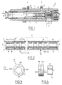
- la Figure 1 est une vue schématique partielle en coupe longitudinale d'une pompe cryogénique suivant l'invention ;
- la Figure 2 est une vue analogue à plus grande échelle du piston de cette pompe ;
- la Figure 3 est une vue en bout d'un segment d'étanchéité de cette pompe; et
- la Figure 4 est une vue de côté du même segment d'étanchéité, avec son expandeur décalé axialement pour la clarté du dessin.
- Figure 1 is a partial schematic view in longitudinal section of a cryogenic pump according to the invention;
- Figure 2 is a similar view on a larger scale of the piston of this pump;
- Figure 3 is an end view of a sealing segment of this pump; and
- Figure 4 is a side view of the same sealing segment, with its expander axially offset for clarity of the drawing.
La pompe cryogénique 1 représentée schématiquement
sur la Figure 1 comprend un corps de pompe 2 dans lequel est
fixée une chemise 3. Dans cette chemise, un piston 4
coulisse en va-et-vient sous l'action d'un système
d'entraínement schématisé par une double flèche F. The cryogenic pump 1 shown diagrammatically
in Figure 1 comprises a
A l'exception des segments du piston, qui seront
décrits plus loin, la structure de la pompe est classique.
En service, le liquide cryogénique est introduit sous une
basse pression suffisante, via un raccord d'entrée 5 muni
d'un clapet d'entrée, dans une chambre annulaire 6. Lorsque
le piston recule (vers la gauche de la Figure 1), le liquide
passe de la chambre 6, via des conduits obliques 7, dans la
chemise 3. Lorsque le piston avance, le liquide est refoulé
sous la haute pression à travers un conduit de refoulement
8, via un clapet de sortie.With the exception of the piston rings, which will
described below, the structure of the pump is conventional.
In service, the cryogenic liquid is introduced under a
sufficient low pressure, via an inlet connection 5 provided
an inlet valve, in an annular chamber 6. When
the piston moves back (to the left of Figure 1), the liquid
passes from chamber 6, via oblique conduits 7, into the
Un excès de liquide sous la basse pression est en
permanence évacué via un espace annulaire 9 du corps 2 qui
entoure la chemise 3, et de là via un raccord 10. La chemise
est centrée dans le corps 2 par une plage 11 située à gauche
de l'espace 9, et une chambre annulaire de fuite 12 est
ménagée à gauche de la plage 11. Le liquide de fuite
recueilli dans la chambre 12 est évacué via un raccord 13.An excess of liquid under the low pressure is in
permanently evacuated via an
La chemise 1 comporte un alésage central à section
circulaire, et son axe X-X est supposé horizontal ou
légèrement incliné dans le sens ascendant vers la sortie 8.The jacket 1 has a central section bore
circular, and its X-X axis is assumed to be horizontal or
slightly inclined in the upward direction towards
Le piston 4 comprend un corps 14 extérieurement
cylindrique, de rayon légèrement inférieur au rayon
intérieur de la chemise 3. Ce corps est pourvu
extérieurement de deux types de gorges circulaires : au
voisinage de chaque extrémité, une gorge 15 de longueur L
relativement importante, et entre les deux gorges 15, une
pluralité de gorges 16 de longueur l plus faible. L'ensemble
des gorges 16 définit une région d'étanchéité 17 du piston.The
Dans chaque gorge 15 est reçu un segment de guidage
18 ayant sensiblement la longueur L. Ce segment est un
anneau à coupe droite ou biaise et comporte sur sa surface
extérieure des rainures longitudinales d'équilibrage.In each
Dans chaque gorge 10 est reçu un segment
d'étanchéité 19 représenté sur les Figures 2 et 3 à l'état
de repos. Ce segment est constitué de deux segments
élémentaires 19A, 19B identiques, à coupe 20A, 20B droite
comme représenté. Chaque segment élémentaire a une longueur
sensiblement égale à l/2. Les deux segments élémentaires
sont accolés, et leurs coupes sont décalées angulairement de
180° l'une par rapport à l'autre. Dans chaque paire de
segments 19A, 19B est disposé un expandeur intérieur 21
annulaire fendu à coupe droite en acier inoxydable
austénitique ou en un autre matériau équivalent, de longueur
sensiblement égale à l. La fente 22 de cet expandeur,
orientée axialement, est décalée au montage de 90° par
rapport à celles des deux segments élémentaires 19A et 19B.In each
Les segments élémentaires sont constitués d'un
matériau fritté sous pression à chaud et composé d'environ
30% de PTFE, d'environ 65% de bronze et d'environ 5% de
bisulfure de molybdène MoS2. Les segments 18 sont constitués
du même matériau.The elementary segments are made of a material sintered under hot pressure and composed of approximately 30% of PTFE, approximately 65% of bronze and approximately 5% of molybdenum disulphide MoS 2 . The
A l'état monté, le jeu circonférentiel de chaque
segment élémentaire 19A, 19B est inférieur à 0,1 mm à
l'emplacement de sa coupe, et il en est de même pour chaque
segment de guidage 18.In the assembled state, the circumferential clearance of each
La pompe décrite ci-dessus, avec huit segments
d'étanchéité 19 régulièrement répartis sur la longueur de la
région 17, qui est d'environ 15 cm pour une longueur de
piston d'environ 20 cm, s'est révélée convenir pour un
fonctionnement continu sans maintenance d'au moins 500
heures par périodes de cinq jours sans arrêt, avec une
pression de refoulement inférieure ou égale à 850 bars et
une charge variant de 30 à 100%. Cette variation de charge
correspond dans cet exemple à une vitesse linéaire moyenne
du piston variant de 0,15 à 0,7 m/s environ. Une telle gamme
de vitesses moyennes, inférieures à 1 m/s, conduit à une
relativement faible usure des pièces.The pump described above, with eight
Claims (14)
Applications Claiming Priority (2)
| Application Number | Priority Date | Filing Date | Title |
|---|---|---|---|
| FR0001733 | 2000-02-11 | ||
| FR0001733A FR2805006B1 (en) | 2000-02-11 | 2000-02-11 | VERY HIGH PRESSURE CRYOGENIC PUMP |
Publications (1)
| Publication Number | Publication Date |
|---|---|
| EP1124061A1 true EP1124061A1 (en) | 2001-08-16 |
Family
ID=8846919
Family Applications (1)
| Application Number | Title | Priority Date | Filing Date |
|---|---|---|---|
| EP01400294A Withdrawn EP1124061A1 (en) | 2000-02-11 | 2001-02-06 | High pressure cryogenic pump |
Country Status (5)
| Country | Link |
|---|---|
| US (1) | US20030080512A1 (en) |
| EP (1) | EP1124061A1 (en) |
| KR (1) | KR20010082069A (en) |
| CA (1) | CA2335490A1 (en) |
| FR (1) | FR2805006B1 (en) |
Cited By (1)
| Publication number | Priority date | Publication date | Assignee | Title |
|---|---|---|---|---|
| CN109798233A (en) * | 2019-03-25 | 2019-05-24 | 中盐安徽红四方股份有限公司 | Modified cryogenic liquid pump |
Families Citing this family (10)
| Publication number | Priority date | Publication date | Assignee | Title |
|---|---|---|---|---|
| CH703376B1 (en) | 2010-06-21 | 2014-05-15 | Fives Cryomec Ag | Reciprocating piston pump for cryogenic fluids. |
| CN102889191A (en) * | 2011-07-21 | 2013-01-23 | 烟台杰瑞石油装备技术有限公司 | Plunger pump used for pumping ultralow-temperature liquid nitrogen |
| JP5519857B1 (en) | 2013-12-26 | 2014-06-11 | 三井造船株式会社 | Low-temperature liquefied gas suction / discharge valve body, reciprocating pump, and fuel gas supply device |
| CH709894A1 (en) | 2014-07-25 | 2016-01-29 | Fives Cryomec Ag | Reciprocating piston pump for cryogenic fluids. |
| US10273955B2 (en) | 2016-11-15 | 2019-04-30 | Caterpillar Inc. | Piston cartridge for piston pump |
| RU2684739C2 (en) * | 2017-03-16 | 2019-04-12 | Общество с ограниченной ответственностью "ПРОМГАЗ-ТЕХНОЛОГИЙ" | Piston cryogenic pump |
| US11326694B2 (en) * | 2019-12-17 | 2022-05-10 | Acd, Llc | Cryogenic piston ring improvement |
| FR3115332B1 (en) * | 2020-10-19 | 2022-12-02 | F2M | Pump comprising cooling means |
| WO2022084072A1 (en) * | 2020-10-19 | 2022-04-28 | F2M | Pump comprising cooling means |
| US20230287875A1 (en) * | 2022-03-08 | 2023-09-14 | Air Products And Chemicals, Inc. | Apparatus and method for cryogenic pump cooldown |
Citations (7)
| Publication number | Priority date | Publication date | Assignee | Title |
|---|---|---|---|---|
| DE1143528B (en) * | 1957-10-25 | 1963-02-14 | Union Carbide Corp | Piston pump for conveying low-boiling liquefied gases |
| US3145629A (en) * | 1960-12-13 | 1964-08-25 | Union Carbide Corp | Cryogenic pump sealing rings |
| FR2307006A1 (en) * | 1975-04-11 | 1976-11-05 | Du Pont | PROCESS FOR PREPARING AGGLOMERATED GRANULES OF TETRAFLUOROETHYLENE POLYMER AND A METAL FILLER |
| AU6808381A (en) * | 1975-12-24 | 1981-06-25 | Commonwealth Scientific And Industrial Research Organisation | Two-component piston ring |
| US4767123A (en) * | 1985-09-02 | 1988-08-30 | Leybold-Heraeus Gmbh | Dual ring piston-ring system with spring ring bias means |
| US5493953A (en) * | 1994-11-14 | 1996-02-27 | Thomas Industries Inc. | Cylinder and piston for compressor or vacuum pump |
| US5763082A (en) * | 1992-02-05 | 1998-06-09 | Daikin Industries, Ltd. | Polytetrafluoroethylene molding powder |
-
2000
- 2000-02-11 FR FR0001733A patent/FR2805006B1/en not_active Expired - Fee Related
-
2001
- 2001-02-06 EP EP01400294A patent/EP1124061A1/en not_active Withdrawn
- 2001-02-08 KR KR1020010006104A patent/KR20010082069A/en not_active Application Discontinuation
- 2001-02-09 CA CA002335490A patent/CA2335490A1/en not_active Abandoned
- 2001-02-12 US US09/780,515 patent/US20030080512A1/en not_active Abandoned
Patent Citations (7)
| Publication number | Priority date | Publication date | Assignee | Title |
|---|---|---|---|---|
| DE1143528B (en) * | 1957-10-25 | 1963-02-14 | Union Carbide Corp | Piston pump for conveying low-boiling liquefied gases |
| US3145629A (en) * | 1960-12-13 | 1964-08-25 | Union Carbide Corp | Cryogenic pump sealing rings |
| FR2307006A1 (en) * | 1975-04-11 | 1976-11-05 | Du Pont | PROCESS FOR PREPARING AGGLOMERATED GRANULES OF TETRAFLUOROETHYLENE POLYMER AND A METAL FILLER |
| AU6808381A (en) * | 1975-12-24 | 1981-06-25 | Commonwealth Scientific And Industrial Research Organisation | Two-component piston ring |
| US4767123A (en) * | 1985-09-02 | 1988-08-30 | Leybold-Heraeus Gmbh | Dual ring piston-ring system with spring ring bias means |
| US5763082A (en) * | 1992-02-05 | 1998-06-09 | Daikin Industries, Ltd. | Polytetrafluoroethylene molding powder |
| US5493953A (en) * | 1994-11-14 | 1996-02-27 | Thomas Industries Inc. | Cylinder and piston for compressor or vacuum pump |
Cited By (2)
| Publication number | Priority date | Publication date | Assignee | Title |
|---|---|---|---|---|
| CN109798233A (en) * | 2019-03-25 | 2019-05-24 | 中盐安徽红四方股份有限公司 | Modified cryogenic liquid pump |
| CN109798233B (en) * | 2019-03-25 | 2020-10-09 | 中盐安徽红四方股份有限公司 | Improved deep cooling liquid pump |
Also Published As
| Publication number | Publication date |
|---|---|
| US20030080512A1 (en) | 2003-05-01 |
| CA2335490A1 (en) | 2001-08-11 |
| FR2805006A1 (en) | 2001-08-17 |
| FR2805006B1 (en) | 2002-06-14 |
| KR20010082069A (en) | 2001-08-29 |
Similar Documents
| Publication | Publication Date | Title |
|---|---|---|
| EP1124061A1 (en) | High pressure cryogenic pump | |
| US8356819B2 (en) | Low and reverse pressure application hydrodynamic pressurizing seals | |
| FR2680392A1 (en) | PRIMER PUMP STAGE PUMP ARRANGEMENT AND UPSTREAM GAS PUMP. | |
| FR2782122A1 (en) | SEALING ARRANGEMENT WITH AUTOMATIC GAME ADJUSTMENT | |
| FR2675863A1 (en) | RADIAL HYDROSTATIC BEARING WITH POCKETS FOR A SERVICE CYLINDER. | |
| FR2590649A1 (en) | PRESSURE-RELATED ROTATING PASSAGE, WHICH CAN BE MANEUVERED | |
| FR3112817A3 (en) | Fuel pump for a direct injection system | |
| FR2828718A1 (en) | RELEASE SYSTEM | |
| FR2465933A1 (en) | IMPROVED PRESS-CUTTING INSERT FOR HIGH-PRESSURE OPERATING PISTON MACHINES | |
| CA2949729C (en) | High-pressure rotary seal-plug assembly with expandable continuous ring | |
| FR2649163A1 (en) | HYDROSTATIC MACHINE WITH VOLUMETRIC DISPLACEMENT | |
| NL2022585B1 (en) | Radial sealing system | |
| FR2544828A1 (en) | SEALING DEVICE FOR TUBE ETAMBOT | |
| FR2704923A1 (en) | Shaft seal with sealing rings arranged one behind the other. | |
| EP0484209B1 (en) | Retractable axial bearing with flexible membrane for a rotary machine | |
| EP0421900A1 (en) | Sealing of a cylindrical part, moving axially and/or rotarily in a chamber | |
| FR2562201A1 (en) | Sealing device for movable seals of pipework for fluids | |
| FR3133812A1 (en) | Hydraulic pressure generator module for a braking system | |
| FR2511109A1 (en) | HYDROSTATIC DEVICE FOR SEPARATING TWO CHAMBERS EMPLOYED BY FLUID UNDER DIFFERENT PRESSURES | |
| BE694996A (en) | ||
| EP4158225A1 (en) | Improved sealing device for a hydraulic machine | |
| CH476934A (en) | Leak-controlled packing | |
| FR3125849A1 (en) | Pressure control on a slide bearing | |
| FR3120662B1 (en) | Scroll compressor with hydrostatic lower bearing arrangement | |
| FR3033381A1 (en) | FLOATING BALL JOINT |
Legal Events
| Date | Code | Title | Description |
|---|---|---|---|
| PUAI | Public reference made under article 153(3) epc to a published international application that has entered the european phase |
Free format text: ORIGINAL CODE: 0009012 |
|
| AK | Designated contracting states |
Kind code of ref document: A1 Designated state(s): AT CH DE FR GB IT LI |
|
| AX | Request for extension of the european patent |
Free format text: AL;LT;LV;MK;RO;SI |
|
| 17P | Request for examination filed |
Effective date: 20010630 |
|
| RAP1 | Party data changed (applicant data changed or rights of an application transferred) |
Owner name: L'AIR LIQUIDE, S.A. A DIRECTOIRE ET CONSEIL DE SUR |
|
| AKX | Designation fees paid |
Free format text: AT CH DE FR GB IT LI |
|
| STAA | Information on the status of an ep patent application or granted ep patent |
Free format text: STATUS: THE APPLICATION IS DEEMED TO BE WITHDRAWN |
|
| 18D | Application deemed to be withdrawn |
Effective date: 20060927 |