EP1123839A2 - Rear view mirror - Google Patents
Rear view mirror Download PDFInfo
- Publication number
- EP1123839A2 EP1123839A2 EP01102549A EP01102549A EP1123839A2 EP 1123839 A2 EP1123839 A2 EP 1123839A2 EP 01102549 A EP01102549 A EP 01102549A EP 01102549 A EP01102549 A EP 01102549A EP 1123839 A2 EP1123839 A2 EP 1123839A2
- Authority
- EP
- European Patent Office
- Prior art keywords
- mirror according
- diaphragm
- housing
- mirror
- carrier
- Prior art date
- Legal status (The legal status is an assumption and is not a legal conclusion. Google has not performed a legal analysis and makes no representation as to the accuracy of the status listed.)
- Granted
Links
- 239000000463 material Substances 0.000 claims description 2
- 230000007704 transition Effects 0.000 claims description 2
- 238000009434 installation Methods 0.000 abstract description 2
- 239000011521 glass Substances 0.000 description 2
- 230000002787 reinforcement Effects 0.000 description 2
- 230000003716 rejuvenation Effects 0.000 description 1
Images


Classifications
-
- B—PERFORMING OPERATIONS; TRANSPORTING
- B60—VEHICLES IN GENERAL
- B60R—VEHICLES, VEHICLE FITTINGS, OR VEHICLE PARTS, NOT OTHERWISE PROVIDED FOR
- B60R1/00—Optical viewing arrangements; Real-time viewing arrangements for drivers or passengers using optical image capturing systems, e.g. cameras or video systems specially adapted for use in or on vehicles
- B60R1/12—Mirror assemblies combined with other articles, e.g. clocks
- B60R2001/1284—Mirror assemblies combined with other articles, e.g. clocks with communication systems other than radio-receivers, e.g. keyless entry systems, navigation systems; with anti-collision systems
Abstract
Der Außenrückblickspiegel hat einen Spiegelkopf (1), der mit einem Gehäuse (3) versehen ist, in dem ein Träger (2) für das Gehäuse (3) untergebracht ist. Um den Außenrückblickspiegel so auszubilden, daß er zur Aufbewahrung eines Senders eines Garagentoröffners geeignet ist, hat das Gehäuse (3) eine Öffnung, die mit einer Blende (4) verschließbar ist. Sie ist mit einem Senderteil (5) des Garagentoröffners versehen. Das Senderteil (5) des Garagentoröffners kann an der Blende (4) angeordnet werden, so daß es fest im Außenrückblickspiegel untergebracht ist. Da die Blende (4) mit dem Senderteil (5) versehen ist, ist eine einfache Montage des Senderteiles (5) gewährleistet. <IMAGE>The exterior rearview mirror has a mirror head (1) which is provided with a housing (3) in which a carrier (2) for the housing (3) is accommodated. In order to design the exterior rearview mirror so that it is suitable for storing a transmitter of a garage door opener, the housing (3) has an opening which can be closed with a cover (4). It is provided with a transmitter part (5) of the garage door opener. The transmitter part (5) of the garage door opener can be arranged on the panel (4), so that it is firmly housed in the exterior rear view mirror. Since the cover (4) is provided with the transmitter part (5), simple installation of the transmitter part (5) is ensured. <IMAGE>
Description
Die Erfindung betrifft einen Außenrückblickspiegel nach dem Oberbegriff
des Anspruches 1.The invention relates to an exterior rear view mirror according to the preamble
of
Zum Öffnen von Garagentoren sind Garagentoröffner bekannt, deren Senderteile im Kraftfahrzeug lose mitgeführt werden und denen in der Garage ein Empfänger zugeordnet ist. Diese Senderteile haben den Nachteil, daß sie häufig im Fahrzeug verlegt werden, so daß der Fahrer den Sender zum Öffnen bzw. Schließen der Garage häufig nicht schnell genug finden kann.Garage door openers are known for opening garage doors Transmitter parts in the vehicle are carried loose and those in the Garage is assigned to a recipient. These transmitter parts have the Disadvantage that they are often moved in the vehicle, so that the driver often do not use the transmitter to open or close the garage can find quickly enough.
Der Erfindung liegt die Aufgabe zugrunde, einen Außenrückblickspiegel der eingangs genannten Art so auszubilden, daß er zur Aufbewahrung des Senders des Garagentoröffners geeignet ist.The invention has for its object an exterior rearview mirror of the type mentioned in such a way that it is for storage the transmitter of the garage door opener is suitable.
Diese Aufgabe wird bei einem Außenrückblickspiegel der gattungsbildenden
Art erfindungsgemäß mit den kennzeichnenden Merkmalen
des Anspruches 1 gelöst.This task is done with an external rearview mirror of the generic
Art according to the invention with the characteristic features
of
Infolge der erfindungsgemäßen Ausbildung kann das Senderteil des Garagentoröffners an der Blende angeordnet werden, so daß es fest im Außenrückblickspiegel untergebracht ist. Im Kraftfahrzeug ist ein Einbauraum für das Senderteil nicht erforderlich. Da die Blende mit dem Senderteil versehen ist, ist eine einfache Montage des Senderteiles gewährleistet. Es läßt sich durch Abnehmen der Blende auch einfach ausbauen.As a result of the training according to the invention, the transmitter part of the Garage door opener can be placed on the bezel so that it is fixed is housed in the exterior rearview mirror. In the motor vehicle is a Installation space for the transmitter part is not required. Since the aperture with is provided the transmitter part is a simple assembly of the transmitter part guaranteed. It can also be removed by removing the bezel simply remove.
Weitere Merkmale der Erfindung ergeben sich aus den weiteren Ansprüchen, der Beschreibung und den Zeichnungen.Further features of the invention result from the further claims, the description and the drawings.
Die Erfindung wird nachstehend anhand eines in den Zeichnungen dargestellten Ausführungsbeispieles näher beschreiben. Es zeigen
- Fig. 1
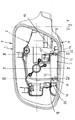
- in perspektivischer Darstellung einen Spiegelkopf eines erfindungsgemäßen Außenrückblickspiegels mit einer Blende, die an einem Gehäuse des Spiegelkopfes gehalten ist,
- Fig. 2
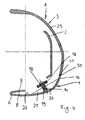
- einen Schnitt längs der Line II-II in Fig. 1,
- Fig. 3
- einen Schnitt längs der Linie III-III in Fig. 1,
- Fig. 4
- einen Schnitt längs der Linie IV-IV in Fig. 1,
- Fig. 5
- die Blende in Ansicht gemäß Pfeil V in Fig. 6,
- Fig. 6
- die Blende in Ansicht gemäß Pfeil VI in Fig. 5.
- Fig. 1
- a perspective view of a mirror head of an exterior rearview mirror according to the invention with a diaphragm which is held on a housing of the mirror head,
- Fig. 2
- 2 shows a section along the line II-II in FIG. 1,
- Fig. 3
- 2 shows a section along the line III-III in FIG. 1,
- Fig. 4
- 2 shows a section along the line IV-IV in FIG. 1,
- Fig. 5
- the aperture in view according to arrow V in Fig. 6,
- Fig. 6
- the aperture in view according to arrow VI in Fig. 5th
Der in den Fig. 1 bis 6 dargestellte Spiegelkopf 1 eines Außenrückblickspiegels
enthält ein Senderteil 5 zum Betätigen eines Garagentoröffners.
Der Spiegelkopf 1 hat einen Träger 2 für einen (nicht dargestellten)
Spiegelglasträger und ein Gehäuse 3, an dem eine Blende
4 gehalten wird. Der Spiegelkopf 1 ist in bekannter Weise abklappbar
mit einem (nicht dargestellten) Spiegelfuß verbunden, mit dem der
Außenrückblickspiegel am Kraftfahrzeug befestigt ist. Die konstruktive
Ausbildung des Spiegelkopfes 1 ist bekannt und wird darum nicht
näher beschrieben.
Das Senderteil 5 des (nicht dargestellten) Garagentoröffners ist auf
der Innenseite 27 der Blende 4 angeordnet.The
Die Blende 4 ist an einer Unterseite 6 des Gehäuses 3 in einer Gehäuseöffnung
7 gehalten (Fig. 1 bis 4) und hat, wie Fig. 5 zeigt, etwa
rechteckigen Umriß. Die Blende 4 erstreckt sich annähernd über die
ganze Länge der Unterseite 6 des Gehäuses 3. In ihrer Formgebung
ist die Blende 4 so an das Gehäuse 3 angepaßt, daß sie eine stetige
Fortsetzung der angrenzenden Bereiche des Gehäuses bildet. Mit
ihrem vorderen Längsrand 8 (Fig. 3) liegt die Blende an einem Längsrand
9 der Öffnung 7 stoßend an, der nahe einer das Spiegelglas
enthaltenden Öffnung 28 des Gehäuses 3 in dessen Unterseite 6
vorgesehen ist. Der andere Längsrand 10 der Blende 4 liegt in der in
Fahrrichtung F weisenden Vorderseite 29 des Gehäuses 3 und ist
verjüngt ausgebildet. Dadurch hat dieser Längsrand 10 einen in der
Dicke verringerten Randteil 30, der einen in der Dicke verringerten
Randteil 11 des Randes 12 der Öffnung 7 übergreift. Wie Fig. 2 zeigt,
ist die Vorderseite 29 des Gehäuses 3 etwa in halber Länge des
Randes 12 der Öffnung 7 innenseitig mit einer Verstärkung 13 versehen,
die im Ausführungsbeispiel dreieckigen Querschnitt hat. Die
Verstärkung 13 verjüngt sich nach innen.The
Auf der Innenseite 27 der Blende 4 aufliegend (Fig. 4) wird das als
Modul 5 ausgebildete Senderteil mit Halteteilen 14 und 15 gehalten.
Das Halteteil 14 ist eine Schraube (Fig. 4), die in einen Befestigungsdom
19 geschraubt wird, der von der Innenseite 27 der Blende
4 absteht und vorzugsweise einstückig mit ihr ausgebildet ist (Fig. 4).
Das Halteteil 15 (Fig. 3) ist ein schmaler, von der Innenseite 27 der
Blende 4 schräg abstehender und vorzugsweise einstückig mit ihr
ausgebildeter Steg, der am freien Ende einen Haken 15' aufweist.
Das Gehäuse des Senderteiles 5 hat an zwei einander gegenüberliegenden
Seiten 33, 34 vorgesehene abstehende Laschen 16, 17, die
jeweils mit einer Öffnung 18, 19 versehen sind. Durch die Öffnung 18
ragt die Schraube 14 und durch die Öffnung 19 der Steg 15, dessen
hakenförmiges Ende 15 die Lasche 16 hintergreift (Fig. 1, 3 und 6).Lying on the
Die Blende 4 erstreckt sich, wie die Fig. 2 bis 4 zeigen, von der Unterseite
6 des Gehäuses 3 bogenförmig gekrümmt in dessen Vorderseite
29. Im Übergangsbereich 20 ist die Blende 4 innenseitig mit
zwei Rippen 21, 22 versteift, die mit Abstand voneinander angeordnet
sind und sich quer zur Längsrichtung der Blende erstrecken (Fig. 1, 5
und 6). In Seitenansicht (Fig. 3 und 4) haben die Rippen 21, 22 etwa
Dreieckform. Sie sind vorteilhaft einstückig mit der Blende 4 ausgebildet.
Das Senderteil 5 liegt zwischen den beiden Rippen 21, 22 auf
der Innenseite der Blende 4 auf. Die beiden stegförmig ausgebildeten
Rippen 21, 22 liegen parallel zueinander.The
Die Blende 4 wird am Träger 2 befestigt. Sie kann am Träger 2 eingerastet
werden, so daß eine einfache und schnelle Montage möglich
ist. Es ist aber auch möglich, die Blende 4 am Träger 2 anzuschrauben.
Für diesen Fall stehen von der Innenseite 27 der Blende 4 beiderseits
der Rippen 21, 22 bzw. des Senderteiles 5 zwei Befestigungsdome
25, 26 ab, die vorzugsweise einstückig mit der Blende 4
ausgebildet sind (Fig. 5 und 6) und in deren zentrale Öffnungen 23,
24 (nicht dargestellte) Schrauben zur lösbaren Befestigung der Blende
4 am Träger 2 geschraubt werden können.The
Im Bereich zwischen den Rippen 21, 22 steht von der Innenseite 27
der Blende 4 eine flache Rippe 31 ab (Fig. 2), auf der sich das Senderteil
5 abstützt. Der Träger 2 ist außerdem so ausgebildet, daß er
mit einem abgewinkelten Abschnitt 32 (Fig. 1 und 2) auf dem Senderteil
5 aufliegt und es in seiner Einbaulage zusätzlich sichert.In the area between the
Durch den sicheren Halt der Blende 4 am Spiegelgehäuse 3 ist auch
das Senderteil 5 einwandfrei gesichert. Es ist über eine (nicht dargestellte)
elektrische Verbindung mit einem Betätigungsteil, wie einem
Schalter, einem Knopf oder dergleichen, der im Fahrzeuginneren
vorgesehen ist, betätigbar. Kommt der Fahrer mit seinem Fahrzeug in
die Nähe des Garagentores, kann er auf einfache Weise mit dem Betätigungsteil
das Senderteil 5 aktivieren, das ein Signal an eine Empfangseinheit
des Garagentoröffners abgibt. Hierdurch wird das Garagentor
ferngesteuert geöffnet bzw. geschlossen. Die Blende 4 besteht
aus einem für die vom Senderteil 5 ausgesandten Strahlen
durchlässigen Material.By securely holding the
Claims (15)
dadurch gekennzeichnet, daß das Gehäuse (3) eine Öffnung (7) aufweist, die mit einer Blende (4) verschließbar ist, die mit mindestens einem Senderteil (5) eines Garagentoröffners versehen ist.External rear view mirror with a mirror head which is provided with a housing in which a carrier for the housing is accommodated,
characterized in that the housing (3) has an opening (7) which can be closed with a panel (4) which is provided with at least one transmitter part (5) of a garage door opener.
dadurch gekennzeichnet, daß die Blende (4) am Träger (2) gehalten, vorzugsweise lösbar mit ihm verbunden ist.Mirror according to claim 1,
characterized in that the diaphragm (4) is held on the carrier (2), preferably detachably connected to it.
dadurch gekennzeichnet, daß die Blende (4) mit dem Träger (2) rastend verbunden ist.Mirror according to claim 2,
characterized in that the screen (4) is connected to the carrier (2) in a latching manner.
dadurch gekennzeichnet, daß die Blende (4) am Träger (2) verschraubt ist und vorteilhaft mindestens eine, vorzugsweise zwei in Längsrichtung der Blende mit Abstand voneinander vorgesehene Halteteile (25, 26) für jeweils ein Befestigungsteil, vorzugsweise eine Schraube, aufweist. Mirror according to claim 2,
characterized in that the diaphragm (4) is screwed to the carrier (2) and advantageously has at least one, preferably two holding parts (25, 26) spaced apart from one another in the longitudinal direction of the diaphragm, each for a fastening part, preferably a screw.
dadurch gekennzeichnet, daß die Blende (4) mindestens ein, vorzugsweise zwei mit Abstand nebeneinander liegende weitere Halteteile (14, 15) zum Befestigen des Senderteiles (5) des Garagentoröffners aufweist.Mirror according to one of claims 1 to 4,
characterized in that the panel (4) has at least one, preferably two further holding parts (14, 15) which are spaced next to one another for fastening the transmitter part (5) of the garage door opener.
dadurch gekennzeichnet, daß das eine weitere Halteteil (14) eine Schraube ist, die in einen Aufnahmeteil (19) an der Innenseite (27) der Blende (4) schraubbar ist.Mirror according to claim 5,
characterized in that the one further holding part (14) is a screw which can be screwed into a receiving part (19) on the inside (27) of the diaphragm (4).
dadurch gekennzeichnet, daß das andere weitere Halteteil (15), das vorteilhaft von der Innenseite (27) der Blende (4) absteht, vorzugsweise einstückig mit ihr ausgebildet ist, hakenförmig ausgebildet ist und mit einem Hakenende (15') ein Anschlußteil (16) des Garagentoröffnerteils (5) hintergreift.Mirror according to claim 5 or 6,
characterized in that the other further holding part (15), which advantageously projects from the inside (27) of the diaphragm (4), is preferably formed in one piece with it, is hook-shaped and has a connecting part (16) with a hook end (15 ') of the garage door opener part (5) engages behind.
dadurch gekennzeichnet, daß die weiteren Halteteile (14, 15) mit etwa gleichem Abstand zwischen den benachbarten, vorteilhaft von der Innenseite (27) der Blende (4) abstehenden, vorzugsweise einstückig mit ihr ausgebildeten Halteteilen (25, 26) der Blende (4) vorgesehen sind.Mirror according to one of claims 5 to 7,
characterized in that the further holding parts (14, 15) with approximately the same distance between the adjacent holding parts (25, 26) of the diaphragm (4), preferably protruding from the inside (27) of the diaphragm (4) are provided.
dadurch gekennzeichnet, daß das Senderteil (5) des Garagentoröffners zwischen sich vorzugsweise quer zur Längsrichtung der Blende (4) erstreckenden Versteifungsrippen (21, 22) liegt. Mirror according to one of claims 1 to 8,
characterized in that the transmitter part (5) of the garage door opener lies between stiffening ribs (21, 22) which preferably extend transversely to the longitudinal direction of the panel (4).
dadurch gekennzeichnet, daß sich die Blende (4) von einer Unterseite (6) des Gehäuses (3) aus bis in eine in Fahrtrichtung (F) des Fahrzeuges nach vorn weisende Wand (29) des Gehäuses (3) erstreckt.Mirror according to one of claims 1 to 9,
characterized in that the cover (4) extends from an underside (6) of the housing (3) to a wall (29) of the housing (3) pointing forward in the direction of travel (F) of the vehicle.
dadurch gekennzeichnet, daß die Versteifungsrippen (21, 22) am Übergangsbereich (20) zwischen den beiden Bereichen der Blende (4) liegen.Mirror according to claim 9 or 10,
characterized in that the stiffening ribs (21, 22) are located at the transition region (20) between the two regions of the diaphragm (4).
dadurch gekennzeichnet, daß das Senderteil (5) über seine Seiten (33, 34) ragende, vorteilhaft jeweils Öffnungen (18, 19) für die weiteren Halteteile (14, 15) aufweisende Anschlußteile (16, 17) aufweist.Mirror according to one of claims 1 to 11,
characterized in that the transmitter part (5) has connection parts (16, 17) projecting over its sides (33, 34) and advantageously each having openings (18, 19) for the further holding parts (14, 15).
dadurch gekennzeichnet, daß die Blende (4) über die Halteteile (25, 26) am Träger (2) befestigt ist.Mirror according to one of claims 1 to 12,
characterized in that the diaphragm (4) is fastened to the carrier (2) via the holding parts (25, 26).
dadurch gekennzeichnet, daß die Blende (4) mit ihrer Außenseite eine stetige Fortsetzung der angrenzenden Bereiche des Gehäuses (3) bildet.Mirror according to one of claims 1 to 13,
characterized in that the diaphragm (4) forms a continuous continuation of the adjacent areas of the housing (3) with its outside.
dadurch gekennzeichnet, daß die Blende (4) aus für die vom Senderteil (5) ausgesandten Strahlen durchlässigem Material besteht.Mirror according to one of claims 1 to 14,
characterized in that the diaphragm (4) consists of material which is transparent to the rays emitted by the transmitter part (5).
Applications Claiming Priority (2)
| Application Number | Priority Date | Filing Date | Title |
|---|---|---|---|
| DE20002386U DE20002386U1 (en) | 2000-02-10 | 2000-02-10 | Exterior rear view mirror |
| DE20002386U | 2000-02-10 |
Publications (3)
| Publication Number | Publication Date |
|---|---|
| EP1123839A2 true EP1123839A2 (en) | 2001-08-16 |
| EP1123839A3 EP1123839A3 (en) | 2003-12-03 |
| EP1123839B1 EP1123839B1 (en) | 2008-07-09 |
Family
ID=7937129
Family Applications (1)
| Application Number | Title | Priority Date | Filing Date |
|---|---|---|---|
| EP01102549A Expired - Lifetime EP1123839B1 (en) | 2000-02-10 | 2001-02-06 | Rear view mirror |
Country Status (3)
| Country | Link |
|---|---|
| US (1) | US6443580B2 (en) |
| EP (1) | EP1123839B1 (en) |
| DE (2) | DE20002386U1 (en) |
Families Citing this family (5)
| Publication number | Priority date | Publication date | Assignee | Title |
|---|---|---|---|---|
| WO2004009408A1 (en) * | 2002-07-19 | 2004-01-29 | Magna Donnelly North America, L.L.C. | Rear view mirror with snap connection |
| US6982626B2 (en) * | 2003-08-05 | 2006-01-03 | Ford Motor Company | System and method for activation of remote features from an automotive vehicle |
| ITMI20082132A1 (en) * | 2008-12-02 | 2010-06-03 | Wide Eye S R L | REFLECTIVE DEVICE WITH A WIDE RANGE OF VISUAL, REDUCED DISTORTION AND ANAMORPHOSIS AND REDUCED DISPATCHING OF REFLECTED IMAGES, PARTICULARLY FOR VEHICLES. |
| NL2004141C2 (en) * | 2010-01-25 | 2011-07-26 | Mci Mirror Controls Int Nl Bv | EXTERIOR MIRROR. |
| JP7086029B2 (en) * | 2019-05-10 | 2022-06-17 | 株式会社ホンダロック | Vehicle door mirror device |
Family Cites Families (3)
| Publication number | Priority date | Publication date | Assignee | Title |
|---|---|---|---|---|
| US4447808A (en) * | 1981-09-18 | 1984-05-08 | Prince Corporation | Rearview mirror transmitter assembly |
| DE4423134C2 (en) * | 1994-07-01 | 1998-07-30 | Reitter & Schefenacker Gmbh | Interior rear view mirror for motor vehicles |
| US6019475A (en) * | 1994-09-30 | 2000-02-01 | Donnelly Corporation | Modular rearview mirror assembly including an electronic control module |
-
2000
- 2000-02-10 DE DE20002386U patent/DE20002386U1/en not_active Expired - Lifetime
-
2001
- 2001-02-06 EP EP01102549A patent/EP1123839B1/en not_active Expired - Lifetime
- 2001-02-06 DE DE50114080T patent/DE50114080D1/en not_active Expired - Lifetime
- 2001-02-09 US US09/780,048 patent/US6443580B2/en not_active Expired - Fee Related
Non-Patent Citations (1)
| Title |
|---|
| None |
Also Published As
| Publication number | Publication date |
|---|---|
| DE20002386U1 (en) | 2000-03-30 |
| EP1123839B1 (en) | 2008-07-09 |
| US6443580B2 (en) | 2002-09-03 |
| EP1123839A3 (en) | 2003-12-03 |
| US20010013982A1 (en) | 2001-08-16 |
| DE50114080D1 (en) | 2008-08-21 |
Similar Documents
| Publication | Publication Date | Title |
|---|---|---|
| DE102005002686A1 (en) | Housing for electrical or electronic components e.g. camera, sensors provided behind disk of vehicle, in particular motor vehicle has at least one flap movable from its closing position into opening position guided away by disk | |
| EP0380013B1 (en) | Device for fastening a roof liner to the construction of a sliding sun roof of a sliding pivoting sun roof | |
| EP1211133B1 (en) | Vehicle internal rear view mirror | |
| DE112008004162T5 (en) | Vehicle window panel | |
| EP1120312A2 (en) | Exterior rear view mirror for vehicles, in particular for automotive vehicles | |
| EP0374421A2 (en) | Wind deflectors for motor vehicle roofs, removable roof segments or the like | |
| WO2005113291A1 (en) | Exterior rearview mirror for vehicles, especially for motor vehicles | |
| DE3308065C2 (en) | ||
| DE102004032682A1 (en) | Column panel for a motor vehicle | |
| DE102016005287A1 (en) | Tailgate with rear view camera | |
| EP1123839A2 (en) | Rear view mirror | |
| DE3607725C2 (en) | ||
| DE1455750A1 (en) | Storage compartment in motor vehicles | |
| EP0675295A1 (en) | Fixing device | |
| DE19721596C2 (en) | Light, in particular rear light, for vehicles, preferably motor vehicles | |
| DE2931038C3 (en) | Dashboard mounting | |
| DE3244655C2 (en) | ||
| EP1633601B1 (en) | External rearview mirror for vehicles, preferably motor vehicles | |
| DE2658745C2 (en) | Cleaning system for the rear window of a motor vehicle | |
| EP0548483A2 (en) | Vehicle roof | |
| DE3008031C2 (en) | ||
| DE102004042903A1 (en) | Exterior rearview mirror for vehicles, preferably for motor vehicles | |
| EP1304262A2 (en) | Interior light for vehicle | |
| EP1177947A2 (en) | Vehicle exterior rear view mirror | |
| DE7824091U1 (en) | Car storage box |
Legal Events
| Date | Code | Title | Description |
|---|---|---|---|
| PUAI | Public reference made under article 153(3) epc to a published international application that has entered the european phase |
Free format text: ORIGINAL CODE: 0009012 |
|
| AK | Designated contracting states |
Kind code of ref document: A2 Designated state(s): AT BE CH CY DE DK ES FI FR GB GR IE IT LI LU MC NL PT SE TR |
|
| AX | Request for extension of the european patent |
Free format text: AL;LT;LV;MK;RO;SI |
|
| PUAL | Search report despatched |
Free format text: ORIGINAL CODE: 0009013 |
|
| AK | Designated contracting states |
Kind code of ref document: A3 Designated state(s): AT BE CH CY DE DK ES FI FR GB GR IE IT LI LU MC NL PT SE TR |
|
| AX | Request for extension of the european patent |
Extension state: AL LT LV MK RO SI |
|
| 17P | Request for examination filed |
Effective date: 20040503 |
|
| AKX | Designation fees paid |
Designated state(s): DE FR GB |
|
| 17Q | First examination report despatched |
Effective date: 20060803 |
|
| 17Q | First examination report despatched |
Effective date: 20060803 |
|
| GRAP | Despatch of communication of intention to grant a patent |
Free format text: ORIGINAL CODE: EPIDOSNIGR1 |
|
| GRAS | Grant fee paid |
Free format text: ORIGINAL CODE: EPIDOSNIGR3 |
|
| GRAA | (expected) grant |
Free format text: ORIGINAL CODE: 0009210 |
|
| STAA | Information on the status of an ep patent application or granted ep patent |
Free format text: STATUS: THE PATENT HAS BEEN GRANTED |
|
| RAP1 | Party data changed (applicant data changed or rights of an application transferred) |
Owner name: VISIOCORP PATENTS S.A.R.L. |
|
| AK | Designated contracting states |
Kind code of ref document: B1 Designated state(s): DE FR GB |
|
| REG | Reference to a national code |
Ref country code: GB Ref legal event code: FG4D Free format text: NOT ENGLISH |
|
| REF | Corresponds to: |
Ref document number: 50114080 Country of ref document: DE Date of ref document: 20080821 Kind code of ref document: P |
|
| REG | Reference to a national code |
Ref country code: GB Ref legal event code: 732E |
|
| RAP2 | Party data changed (patent owner data changed or rights of a patent transferred) |
Owner name: VISIOCORP PATENTS S.A.R.L. |
|
| PLBE | No opposition filed within time limit |
Free format text: ORIGINAL CODE: 0009261 |
|
| STAA | Information on the status of an ep patent application or granted ep patent |
Free format text: STATUS: NO OPPOSITION FILED WITHIN TIME LIMIT |
|
| 26N | No opposition filed |
Effective date: 20090414 |
|
| REG | Reference to a national code |
Ref country code: FR Ref legal event code: CA Ref country code: FR Ref legal event code: CD |
|
| PGFP | Annual fee paid to national office [announced via postgrant information from national office to epo] |
Ref country code: FR Payment date: 20120227 Year of fee payment: 12 |
|
| PGFP | Annual fee paid to national office [announced via postgrant information from national office to epo] |
Ref country code: DE Payment date: 20120221 Year of fee payment: 12 |
|
| REG | Reference to a national code |
Ref country code: DE Ref legal event code: R082 Ref document number: 50114080 Country of ref document: DE Representative=s name: JONES DAY RECHTSANWAELTE PATENTANWAELTE, DE |
|
| PGFP | Annual fee paid to national office [announced via postgrant information from national office to epo] |
Ref country code: GB Payment date: 20130218 Year of fee payment: 13 |
|
| REG | Reference to a national code |
Ref country code: FR Ref legal event code: ST Effective date: 20131031 |
|
| REG | Reference to a national code |
Ref country code: DE Ref legal event code: R119 Ref document number: 50114080 Country of ref document: DE Effective date: 20130903 |
|
| PG25 | Lapsed in a contracting state [announced via postgrant information from national office to epo] |
Ref country code: DE Free format text: LAPSE BECAUSE OF NON-PAYMENT OF DUE FEES Effective date: 20130903 Ref country code: FR Free format text: LAPSE BECAUSE OF NON-PAYMENT OF DUE FEES Effective date: 20130228 |
|
| GBPC | Gb: european patent ceased through non-payment of renewal fee |
Effective date: 20140206 |
|
| PG25 | Lapsed in a contracting state [announced via postgrant information from national office to epo] |
Ref country code: GB Free format text: LAPSE BECAUSE OF NON-PAYMENT OF DUE FEES Effective date: 20140206 |