EP1122114A2 - Weldable mount for fuel systems component - Google Patents
Weldable mount for fuel systems component Download PDFInfo
- Publication number
- EP1122114A2 EP1122114A2 EP20010300994 EP01300994A EP1122114A2 EP 1122114 A2 EP1122114 A2 EP 1122114A2 EP 20010300994 EP20010300994 EP 20010300994 EP 01300994 A EP01300994 A EP 01300994A EP 1122114 A2 EP1122114 A2 EP 1122114A2
- Authority
- EP
- European Patent Office
- Prior art keywords
- mount
- fuel tank
- welding
- fuel
- weldable
- Prior art date
- Legal status (The legal status is an assumption and is not a legal conclusion. Google has not performed a legal analysis and makes no representation as to the accuracy of the status listed.)
- Withdrawn
Links
Images


Classifications
-
- B—PERFORMING OPERATIONS; TRANSPORTING
- B29—WORKING OF PLASTICS; WORKING OF SUBSTANCES IN A PLASTIC STATE IN GENERAL
- B29C—SHAPING OR JOINING OF PLASTICS; SHAPING OF MATERIAL IN A PLASTIC STATE, NOT OTHERWISE PROVIDED FOR; AFTER-TREATMENT OF THE SHAPED PRODUCTS, e.g. REPAIRING
- B29C66/00—General aspects of processes or apparatus for joining preformed parts
- B29C66/50—General aspects of joining tubular articles; General aspects of joining long products, i.e. bars or profiled elements; General aspects of joining single elements to tubular articles, hollow articles or bars; General aspects of joining several hollow-preforms to form hollow or tubular articles
- B29C66/51—Joining tubular articles, profiled elements or bars; Joining single elements to tubular articles, hollow articles or bars; Joining several hollow-preforms to form hollow or tubular articles
- B29C66/53—Joining single elements to tubular articles, hollow articles or bars
- B29C66/532—Joining single elements to the wall of tubular articles, hollow articles or bars
-
- B—PERFORMING OPERATIONS; TRANSPORTING
- B29—WORKING OF PLASTICS; WORKING OF SUBSTANCES IN A PLASTIC STATE IN GENERAL
- B29C—SHAPING OR JOINING OF PLASTICS; SHAPING OF MATERIAL IN A PLASTIC STATE, NOT OTHERWISE PROVIDED FOR; AFTER-TREATMENT OF THE SHAPED PRODUCTS, e.g. REPAIRING
- B29C65/00—Joining or sealing of preformed parts, e.g. welding of plastics materials; Apparatus therefor
- B29C65/02—Joining or sealing of preformed parts, e.g. welding of plastics materials; Apparatus therefor by heating, with or without pressure
- B29C65/06—Joining or sealing of preformed parts, e.g. welding of plastics materials; Apparatus therefor by heating, with or without pressure using friction, e.g. spin welding
- B29C65/0672—Spin welding
-
- B—PERFORMING OPERATIONS; TRANSPORTING
- B29—WORKING OF PLASTICS; WORKING OF SUBSTANCES IN A PLASTIC STATE IN GENERAL
- B29C—SHAPING OR JOINING OF PLASTICS; SHAPING OF MATERIAL IN A PLASTIC STATE, NOT OTHERWISE PROVIDED FOR; AFTER-TREATMENT OF THE SHAPED PRODUCTS, e.g. REPAIRING
- B29C66/00—General aspects of processes or apparatus for joining preformed parts
- B29C66/01—General aspects dealing with the joint area or with the area to be joined
- B29C66/05—Particular design of joint configurations
- B29C66/10—Particular design of joint configurations particular design of the joint cross-sections
- B29C66/11—Joint cross-sections comprising a single joint-segment, i.e. one of the parts to be joined comprising a single joint-segment in the joint cross-section
- B29C66/112—Single lapped joints
- B29C66/1122—Single lap to lap joints, i.e. overlap joints
-
- B—PERFORMING OPERATIONS; TRANSPORTING
- B29—WORKING OF PLASTICS; WORKING OF SUBSTANCES IN A PLASTIC STATE IN GENERAL
- B29C—SHAPING OR JOINING OF PLASTICS; SHAPING OF MATERIAL IN A PLASTIC STATE, NOT OTHERWISE PROVIDED FOR; AFTER-TREATMENT OF THE SHAPED PRODUCTS, e.g. REPAIRING
- B29C66/00—General aspects of processes or apparatus for joining preformed parts
- B29C66/01—General aspects dealing with the joint area or with the area to be joined
- B29C66/05—Particular design of joint configurations
- B29C66/10—Particular design of joint configurations particular design of the joint cross-sections
- B29C66/12—Joint cross-sections combining only two joint-segments; Tongue and groove joints; Tenon and mortise joints; Stepped joint cross-sections
- B29C66/124—Tongue and groove joints
- B29C66/1246—Tongue and groove joints characterised by the female part, i.e. the part comprising the groove
- B29C66/12469—Tongue and groove joints characterised by the female part, i.e. the part comprising the groove being asymmetric
-
- B—PERFORMING OPERATIONS; TRANSPORTING
- B29—WORKING OF PLASTICS; WORKING OF SUBSTANCES IN A PLASTIC STATE IN GENERAL
- B29C—SHAPING OR JOINING OF PLASTICS; SHAPING OF MATERIAL IN A PLASTIC STATE, NOT OTHERWISE PROVIDED FOR; AFTER-TREATMENT OF THE SHAPED PRODUCTS, e.g. REPAIRING
- B29C66/00—General aspects of processes or apparatus for joining preformed parts
- B29C66/01—General aspects dealing with the joint area or with the area to be joined
- B29C66/05—Particular design of joint configurations
- B29C66/10—Particular design of joint configurations particular design of the joint cross-sections
- B29C66/13—Single flanged joints; Fin-type joints; Single hem joints; Edge joints; Interpenetrating fingered joints; Other specific particular designs of joint cross-sections not provided for in groups B29C66/11 - B29C66/12
- B29C66/131—Single flanged joints, i.e. one of the parts to be joined being rigid and flanged in the joint area
- B29C66/1312—Single flange to flange joints, the parts to be joined being rigid
-
- B—PERFORMING OPERATIONS; TRANSPORTING
- B29—WORKING OF PLASTICS; WORKING OF SUBSTANCES IN A PLASTIC STATE IN GENERAL
- B29C—SHAPING OR JOINING OF PLASTICS; SHAPING OF MATERIAL IN A PLASTIC STATE, NOT OTHERWISE PROVIDED FOR; AFTER-TREATMENT OF THE SHAPED PRODUCTS, e.g. REPAIRING
- B29C66/00—General aspects of processes or apparatus for joining preformed parts
- B29C66/70—General aspects of processes or apparatus for joining preformed parts characterised by the composition, physical properties or the structure of the material of the parts to be joined; Joining with non-plastics material
- B29C66/71—General aspects of processes or apparatus for joining preformed parts characterised by the composition, physical properties or the structure of the material of the parts to be joined; Joining with non-plastics material characterised by the composition of the plastics material of the parts to be joined
- B29C66/712—General aspects of processes or apparatus for joining preformed parts characterised by the composition, physical properties or the structure of the material of the parts to be joined; Joining with non-plastics material characterised by the composition of the plastics material of the parts to be joined the composition of one of the parts to be joined being different from the composition of the other part
-
- B—PERFORMING OPERATIONS; TRANSPORTING
- B60—VEHICLES IN GENERAL
- B60K—ARRANGEMENT OR MOUNTING OF PROPULSION UNITS OR OF TRANSMISSIONS IN VEHICLES; ARRANGEMENT OR MOUNTING OF PLURAL DIVERSE PRIME-MOVERS IN VEHICLES; AUXILIARY DRIVES FOR VEHICLES; INSTRUMENTATION OR DASHBOARDS FOR VEHICLES; ARRANGEMENTS IN CONNECTION WITH COOLING, AIR INTAKE, GAS EXHAUST OR FUEL SUPPLY OF PROPULSION UNITS IN VEHICLES
- B60K15/00—Arrangement in connection with fuel supply of combustion engines or other fuel consuming energy converters, e.g. fuel cells; Mounting or construction of fuel tanks
- B60K15/03—Fuel tanks
- B60K15/035—Fuel tanks characterised by venting means
- B60K15/03519—Valve arrangements in the vent line
-
- B—PERFORMING OPERATIONS; TRANSPORTING
- B29—WORKING OF PLASTICS; WORKING OF SUBSTANCES IN A PLASTIC STATE IN GENERAL
- B29C—SHAPING OR JOINING OF PLASTICS; SHAPING OF MATERIAL IN A PLASTIC STATE, NOT OTHERWISE PROVIDED FOR; AFTER-TREATMENT OF THE SHAPED PRODUCTS, e.g. REPAIRING
- B29C66/00—General aspects of processes or apparatus for joining preformed parts
- B29C66/01—General aspects dealing with the joint area or with the area to be joined
- B29C66/05—Particular design of joint configurations
- B29C66/20—Particular design of joint configurations particular design of the joint lines, e.g. of the weld lines
- B29C66/24—Particular design of joint configurations particular design of the joint lines, e.g. of the weld lines said joint lines being closed or non-straight
- B29C66/242—Particular design of joint configurations particular design of the joint lines, e.g. of the weld lines said joint lines being closed or non-straight said joint lines being closed, i.e. forming closed contours
- B29C66/2422—Particular design of joint configurations particular design of the joint lines, e.g. of the weld lines said joint lines being closed or non-straight said joint lines being closed, i.e. forming closed contours being circular, oval or elliptical
- B29C66/24221—Particular design of joint configurations particular design of the joint lines, e.g. of the weld lines said joint lines being closed or non-straight said joint lines being closed, i.e. forming closed contours being circular, oval or elliptical being circular
-
- B—PERFORMING OPERATIONS; TRANSPORTING
- B29—WORKING OF PLASTICS; WORKING OF SUBSTANCES IN A PLASTIC STATE IN GENERAL
- B29C—SHAPING OR JOINING OF PLASTICS; SHAPING OF MATERIAL IN A PLASTIC STATE, NOT OTHERWISE PROVIDED FOR; AFTER-TREATMENT OF THE SHAPED PRODUCTS, e.g. REPAIRING
- B29C66/00—General aspects of processes or apparatus for joining preformed parts
- B29C66/70—General aspects of processes or apparatus for joining preformed parts characterised by the composition, physical properties or the structure of the material of the parts to be joined; Joining with non-plastics material
- B29C66/71—General aspects of processes or apparatus for joining preformed parts characterised by the composition, physical properties or the structure of the material of the parts to be joined; Joining with non-plastics material characterised by the composition of the plastics material of the parts to be joined
-
- B—PERFORMING OPERATIONS; TRANSPORTING
- B29—WORKING OF PLASTICS; WORKING OF SUBSTANCES IN A PLASTIC STATE IN GENERAL
- B29C—SHAPING OR JOINING OF PLASTICS; SHAPING OF MATERIAL IN A PLASTIC STATE, NOT OTHERWISE PROVIDED FOR; AFTER-TREATMENT OF THE SHAPED PRODUCTS, e.g. REPAIRING
- B29C66/00—General aspects of processes or apparatus for joining preformed parts
- B29C66/80—General aspects of machine operations or constructions and parts thereof
- B29C66/83—General aspects of machine operations or constructions and parts thereof characterised by the movement of the joining or pressing tools
- B29C66/832—Reciprocating joining or pressing tools
- B29C66/8322—Joining or pressing tools reciprocating along one axis
-
- B—PERFORMING OPERATIONS; TRANSPORTING
- B29—WORKING OF PLASTICS; WORKING OF SUBSTANCES IN A PLASTIC STATE IN GENERAL
- B29K—INDEXING SCHEME ASSOCIATED WITH SUBCLASSES B29B, B29C OR B29D, RELATING TO MOULDING MATERIALS OR TO MATERIALS FOR MOULDS, REINFORCEMENTS, FILLERS OR PREFORMED PARTS, e.g. INSERTS
- B29K2023/00—Use of polyalkenes or derivatives thereof as moulding material
- B29K2023/04—Polymers of ethylene
- B29K2023/06—PE, i.e. polyethylene
- B29K2023/0608—PE, i.e. polyethylene characterised by its density
- B29K2023/065—HDPE, i.e. high density polyethylene
-
- B—PERFORMING OPERATIONS; TRANSPORTING
- B29—WORKING OF PLASTICS; WORKING OF SUBSTANCES IN A PLASTIC STATE IN GENERAL
- B29L—INDEXING SCHEME ASSOCIATED WITH SUBCLASS B29C, RELATING TO PARTICULAR ARTICLES
- B29L2031/00—Other particular articles
- B29L2031/712—Containers; Packaging elements or accessories, Packages
- B29L2031/7172—Fuel tanks, jerry cans
-
- B—PERFORMING OPERATIONS; TRANSPORTING
- B60—VEHICLES IN GENERAL
- B60K—ARRANGEMENT OR MOUNTING OF PROPULSION UNITS OR OF TRANSMISSIONS IN VEHICLES; ARRANGEMENT OR MOUNTING OF PLURAL DIVERSE PRIME-MOVERS IN VEHICLES; AUXILIARY DRIVES FOR VEHICLES; INSTRUMENTATION OR DASHBOARDS FOR VEHICLES; ARRANGEMENTS IN CONNECTION WITH COOLING, AIR INTAKE, GAS EXHAUST OR FUEL SUPPLY OF PROPULSION UNITS IN VEHICLES
- B60K15/00—Arrangement in connection with fuel supply of combustion engines or other fuel consuming energy converters, e.g. fuel cells; Mounting or construction of fuel tanks
- B60K15/03—Fuel tanks
- B60K2015/03328—Arrangements or special measures related to fuel tanks or fuel handling
- B60K2015/03447—Arrangements or special measures related to fuel tanks or fuel handling for improving the sealing
-
- Y—GENERAL TAGGING OF NEW TECHNOLOGICAL DEVELOPMENTS; GENERAL TAGGING OF CROSS-SECTIONAL TECHNOLOGIES SPANNING OVER SEVERAL SECTIONS OF THE IPC; TECHNICAL SUBJECTS COVERED BY FORMER USPC CROSS-REFERENCE ART COLLECTIONS [XRACs] AND DIGESTS
- Y10—TECHNICAL SUBJECTS COVERED BY FORMER USPC
- Y10T—TECHNICAL SUBJECTS COVERED BY FORMER US CLASSIFICATION
- Y10T137/00—Fluid handling
- Y10T137/0753—Control by change of position or inertia of system
- Y10T137/0874—Vent opening or closing on tipping container
-
- Y—GENERAL TAGGING OF NEW TECHNOLOGICAL DEVELOPMENTS; GENERAL TAGGING OF CROSS-SECTIONAL TECHNOLOGIES SPANNING OVER SEVERAL SECTIONS OF THE IPC; TECHNICAL SUBJECTS COVERED BY FORMER USPC CROSS-REFERENCE ART COLLECTIONS [XRACs] AND DIGESTS
- Y10—TECHNICAL SUBJECTS COVERED BY FORMER USPC
- Y10T—TECHNICAL SUBJECTS COVERED BY FORMER US CLASSIFICATION
- Y10T137/00—Fluid handling
- Y10T137/2931—Diverse fluid containing pressure systems
- Y10T137/3003—Fluid separating traps or vents
- Y10T137/3084—Discriminating outlet for gas
- Y10T137/309—Fluid sensing valve
- Y10T137/3099—Float responsive
-
- Y—GENERAL TAGGING OF NEW TECHNOLOGICAL DEVELOPMENTS; GENERAL TAGGING OF CROSS-SECTIONAL TECHNOLOGIES SPANNING OVER SEVERAL SECTIONS OF THE IPC; TECHNICAL SUBJECTS COVERED BY FORMER USPC CROSS-REFERENCE ART COLLECTIONS [XRACs] AND DIGESTS
- Y10—TECHNICAL SUBJECTS COVERED BY FORMER USPC
- Y10T—TECHNICAL SUBJECTS COVERED BY FORMER US CLASSIFICATION
- Y10T137/00—Fluid handling
- Y10T137/8593—Systems
- Y10T137/86292—System with plural openings, one a gas vent or access opening
- Y10T137/86324—Tank with gas vent and inlet or outlet
Definitions
- the present invention relates to a weldable mount, and in particular, to a mount adapted to be welded to a base made of a plastics material such as polymeric material. More particularly, the present invention relates to a fuel system component, such as fuel tank vent apparatus, adapted to be mounted on a vehicle fuel tank made of a plastics material using a weldable mount.
- a fuel system component such as fuel tank vent apparatus
- Mounting assemblies are used to mount a fuel system component, such as a venting valve assembly, in a top wall of a fuel tank. See, for example, U.S. Patent No. 4,966,189 to Harris and PCT International Publication No. WO 99/27284 to Foltz, each of which is incorporated herein by reference. Further, U.S. Patent No. 5,404,907 to Benjey et al. And U.S. Patent No. 5,130,043 to Hyde both relate to weldable vapor vent valve systems and are also incorporated by reference herein.
- An apparatus 10 is shown in Fig. 1 and is configured to be mounted on a fuel tank 11 as shown in Fig. 2.
- Apparatus 10 is formed to include a weldable mount 12 and a fuel system component 14 coupled to weldable mount 12.
- the fuel system component 14 is a valve assembly for controlling the discharge of fuel and fuel vapor from fuel tank 11. It is within the scope of this disclosure to use weldable mount 12 to support other fuel system components (not shown) such as a fuel sender unit or other type of valve in a fuel tank or other tank.
- Valve assembly 14 includes a valve housing 16 formed to include a vent chamber 18 communicating with an interior region 19 in fuel tank 11 and a vent passageway 20 communicating with the vent chamber 18.
- Valve housing 16 is made of any suitable structural, engineering-grade plastics material such as acetyl.
- Valve assembly 14 further includes a valve 22 positioned to move in vent chamber 18 to open and close vent passageway 20 and an annular seal 22 arranged to establish a liquid-fuel and fuel-vapor seal between valve housing 16 and weldable mount 12 as shown, for example, in Fig. 2.
- valve 22 is a conventional float valve made of a buoyant material, any suitable closure valve could be used in vent chamber 18.
- float valve 22 is biased in an upward direction by a coiled compression spring (not shown) that is coupled to float valve 22 and arranged to act against a portion of valve housing 16 so that float valve 22 can move upwardly to close vent passageway 20 when float valve 22 is exposed to a rising level of liquid fuel (not shown) inside interior region 19 of fuel tank 11.
- Fuel tank 11 is made of a suitable plastics material such as high-density polyethylene (HDPE). Because valve housing 16 is made of acetyl, it is not weldable directly to fuel tank 11 since acetyl material cannot be welded to HDPE material.
- HDPE high-density polyethylene
- Weldable mount 12 is provided to mount a fuel system component such as valve assembly 14 on fuel tank 11.
- Weldable mount 12 is made of HDPE and can therefore be welded to the HDPE fuel tank 11.
- Valve housing 16 is formed to include separate first or upper and second or lower housing portions 26, 28 as shown in Figs. 1 and 2. Second housing portion 28 is coupled to first housing portion 26 using any suitable means to trap weldable mount 12 and annular seal 24 there between so that a suitable liquid-fuel and fuel-vapor seal will be established between apparatus 10 and fuel tank 11 once weldable mount 12 is welded to fuel tank 11 as shown, for example, in Fig. 2.
- First housing portion 26 includes a circular top wall 30, a venting outlet 32 coupled to and positioned to lie above top wall 30, and first engaging portion 34and second engagin portion 36 in the form of a pair of annular connector ridges 34, 36 (or other suitable structure) coupled to and positioned to lie below top wall 30 as shown best in Fig. 2.
- Venting outlet 32 is formed to include vent passageway 20 and first and second discharge ports 38, 40 communicating with vent passageway 20.
- Circular top wall 30 includes an annular valve housing flange 42 extending radially outwardly from annular connector ridges 34, 36 and providing a downwardly facing flat surface 44 as shown best in Fig. 2.
- Second housing portion 28 includes a cylindrical sleeve 46 formed to include vent chamber 18 therein and an annular mount flange 48 extending radially outwardly from an upper end 50 of cylindrical sleeve 46 as shown best in Fig. 2.
- Upper end 50 of cylindrical sleeve 46 is formed to include a high, thin annular inner rim 52, a lower, thicker, annular outer rim 54 and an annular channel 56 located between rims 52 and 54 as shown in Fig. 2.
- Outer connector ridge 34 is configured to seat on an upwardly facing surface of outer rim 54 and inner connector ridge 36 is configured to extend into annular channel 56 when first housing portion 26 is coupled to second housing portion 28.
- Ultrasonic welding, spin welding, or any other suitable technique can be used to bond acetyl first and second housing portions 26, 28 to one another to establish valve housing 16 and trap annular seal 24 and a portion of weldable mount 12 between annular valve housing flange 42 and annular mount flange 48.
- Weldable mount 12 is formed to include a foot 58 adapted to mate with and be welded to an outer surface 60 of fuel tank 11 and a body 62 formed to include an annular channel 64 having an opening facing toward an underside of annular valve housing flange 42 and receiving annular seal 24 therein.
- An engaging portion portion 66 in the form of a radially inner portion 66 of body 62 is configured to extend into a side-opening annular channel 68 defined by flanges 42, 48 of first and second portions 26, 28and outer rim 54 as shown best in Fig. 2.
- Apparatus 10 is assembled and installed in the following manner.
- Upper housing portion 26 is inverted and mounted in a fixture (not shown).
- Annular seal 24 is placed in circular channel 64 and weldable mount 12 is placed on annular valve housing flange 42 so that annular seal 24 engages surface 44 on flange 42.
- Lower housing portion 28 is then bonded to upper housing portion 26 to trap body 62 of weldable mount 12 and annular seal 24 between flanges 42 and 48 of valve housing 16.
- Apparatus 10 is then turned “right side up” and inserted into a mounting aperture 70 formed in fuel tank 11 as shown, for example, in Fig. 2 and foot 58 of weldable mount 12 is welded or otherwise bonded to outer surface 60 of fuel tank 11 using any suitable technique.
- a first modification to apparatus 10 includes the addition of protrusions in the form of retention posts 72 to weldable mount 12 to produce apparatus 110 as shown in Figs. 3 and 4.
- the base of each retention post 72 is coupled to an upper portion of weldable mount 12 and a middle portion of each retention post 72 is passed through an aperture formed in a peripheral portion of annular valve housing flange 42.
- a tip of each retention post 72 is heat-staked or otherwise formed to fix retention post 72 to flange 42 as shown, for example, in Figs. 3 and 4.
- inversion of upper housing portion 26 is unnecessary during assembly of apparatus 110 since weldable mount 12 can be coupled to flange 42 to trap annular seal 24 in place there between using retention posts 72.
- retention posts 72 are formed of HDPE material to be integral with weldable mount 12.
- a second modification to apparatus 10 includes the addition of a retainer 74 in the form of an annular retention rim 75 to weldable mount 12 to produce apparatus 210 as shown in Figs. 5 and 6.
- the base of retention rim 75 is coupled to an upper portion of weldable mount 12 along the radially outermost edge thereof.
- the free end of retention rim 75 is heat-staked, deformed, or coined radially inwardly as shown, for example, in Fig, 6 to couple weldable mount 12 to annular valve housing flange 42 of valve housing 16.
- inversion of first housing portion 26 is unnecessary during assembly of apparatus 210 since weldable mount 12 can be coupled to flange 42 to trap annular seal 24 in place there between using retention post 72.
- retention rim 75 is formed of HDPE material to be integral with weldable mount 12. It is within the scope of this disclosure to form rim 75 as a continuous 360° strip of material or as a single rim segment or a series of two or more spaced-apart rim segments.
- a third modification to apparatus 10 includes the addition of a retainer 74 in the form of snap connectors 76 to annular valve housing flange 42 and formation of weldable mount 12 to engage snap connectors 76 to retain weldable mount 12 in a fixed position relative to valve housing 16 to produce apparatus 310 as shown in Figs. 7 and 8.
- the base of each snap connector 76 is coupled to a radially outer edge of annular valve housing flange 42.
- a depending hook portion of each snap connector 76 is arranged and configured to extend over a corresponding portion of mount 12. As shown, the hook snaps into or otherwise engages a recess or connector receiver formed in weldable mount 12 as shown in Figs. 7 and 8.
- snap connectors 76 are formed of acetyl material to be integral with upper housing portion 26.
- a fourth modification to apparatus 10 includes the structures as shown in Figs. 9 - 11, the first portion 26 is positioned for engagement with the second portion 28. As shown in Figs. 9 - 11, mount 12 is retained between first portion 26 and second portion 28 and also includes seal 24 retained therebetween.
- the general function of the various structures is generally consistent with that as described herein above.
- Mount 12 as shown in Figs. 9 - 11 is formed with engaging portion 66 and foot 58. As shown in the corresponding figures, engaging portion 66 is retained between first portion 26 and second portion 28 with foot 58 extending therefrom. A flange 90 extends from first portion 28 to overlie a portion of mount 12 to increase engagement with mount 12.
- First and second portions 26, 28 are provided with first and second engaging portions 34, 36. These engaging portions are formed of compatible material to allow first housing portion 26 and second housing portion 28 to be welded together.
- mount 12 is formed of a material that is compatible for welding to surface 60 of the tank 11. While first and second portions 26, 28 of the valve assembly 14 may be incompatible for welding to tank 11, the material for these portions is selected to be compatible for welding to one another.
- apparatus 410 is assembled by welding first portion 26 to second portion 28. Welding the portions 26, 28 together causes the engaging portions 34, 36 (Fig. 10) to be combined as a single engaging portion 94 essentially welded as a uniform piece of material. Engaging portion 94 holds the first portion and second portion together. As the portions 26, 28 are brought together (the dimensional difference 96 in Fig. 10) mount 12 is clamped between first portion and second portion 26, 28. Also, seal 24 is compressed therebetween trapping seal 24 in a corresponding channel 98 providing increased sealing between first portion 26 and second portion 28.
- Apparatus 410 is attached to the fuel tank 11 by means of welding as shown in Fig. 11.
- spin welding is one technique which may be used, as illustrated in Fig. 11.
- apparatus 410 is rotated (100) about central axis 102 and a downward clamping force 104 is applied by a clamp structure 106 to apparatus 410.
- Rotation (100) of apparatus 410 in combination with pressure 104 causes foot 58 to form a bond or become welded to tank 11.
- other bonding or welding techniques may be used to attach foot 58 to tank 11.
- hot plate welding or adhesive technology may be used to bond apparatus 410 to tank 11.
Abstract
Description
- The present invention relates to a weldable mount, and in particular, to a mount adapted to be welded to a base made of a plastics material such as polymeric material. More particularly, the present invention relates to a fuel system component, such as fuel tank vent apparatus, adapted to be mounted on a vehicle fuel tank made of a plastics material using a weldable mount.
- Mounting assemblies are used to mount a fuel system component, such as a venting valve assembly, in a top wall of a fuel tank. See, for example, U.S. Patent No. 4,966,189 to Harris and PCT International Publication No. WO 99/27284 to Foltz, each of which is incorporated herein by reference. Further, U.S. Patent No. 5,404,907 to Benjey et al. And U.S. Patent No. 5,130,043 to Hyde both relate to weldable vapor vent valve systems and are also incorporated by reference herein.
- Features of the present invention will become apparent to those skilled in the art upon consideration of the following detailed description of preferred embodiments exemplifying the best mode of carrying out the invention as presently perceived.
- The detailed description particularly refers to the accompanying figures in which:
- Fig. 1 is a perspective view of a fuel tank vent apparatus including a ring-shaped weldable mount, of a material which is compatible for welding to a fuel tank, carried on a housing made of a generally non-weldable material;
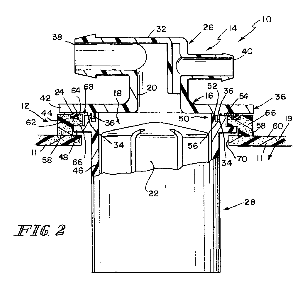
- Fig. 2 is an enlarged sectional view taken along line 2-2 of Fig. 1 showing the ring-shaped weldable mount welded to a fuel tank made of a weldable plastics material so that the fuel system component is mounted on the fuel tank and the valve housing is positioned to lie in a mounting aperture formed in a top wall of the fuel tank and also showing other elements in the fuel system component including a float valve positioned to move up and down in an interior chamber formed in the valve housing and an annular seal positioned to lie in an annular channel formed in a upper portion of the ring-shaped weldable mount so that the annular seal is arranged to engage an underside of an annular valve housing flange included in the valve housing;
- Fig. 3 is a perspective view of another fuel system component that is similar to the apparatus shown in Fig. 1 except that several generally vertical retention posts are appended to the upper portion of the ring-shaped weldable mount and configured to couple the weldable mount to the annular valve housing flange overlying the weldable mount;
- Fig. 4 is an enlarged sectional view taken along line 4-4 of Fig. 3 showing a section through one of the retention posts provided to couple the ring-shaped weldable mount to an underside of the annular valve housing flange;
- Fig. 5 is a perspective view of yet another system component that is similar to the apparatus shown in Figs. 1 and 3 except that an annular retention rim is appended to the upper portion of the ring-shaped weldable mount and configured to couple the weldable mount to the annular valve housing flange;
- Fig. 6 is an enlarged sectional view taken along line 6-6 of Fig. 5 showing use of portions of the retention rim to couple the ring-shaped weldable mount to an underside of the annular valve housing flange;
- Fig. 7 is a perspective view of still another fuel tank vent apparatus that is similar to the apparatus shown in Figs. 1, 3, and 5 except that several spaced-apart retainers are appended to the upper portion of the ring-shaped weldable mount and configured to couple the weldable mount to the annular valve housing flange;
- Fig. 8 is a sectional view taken along line 8-8 of Fig. 7 showing use of two of the retainers to couple the ring-shaped weldable mount to an underside of the annular valve housing flange;
- Fig. 9 is an exploded, enlarged sectional view similar to those as shown in Figs. 2, 4, 6 and 8 in which a fuel system component is positioned for mounting to a fuel tank, and in which Fig. 9 shows a first portion and a second portion of the fuel component positioned for retaining a seal there between and in which said mount is positioned with a portion thereof to be retained between the first portion and the second portion and the mount having a foot extending from between the first portion and the second portion;
- Fig. 10 is an assembled sectional view of the assembly as shown in Fig. 9 in which the assembly has been positioned for installation on the fuel tank; and
- Fig. 11 is a sectional view similar to that as shown in Fig. 10 and in which the assembly is rotated about a central axis and a force is applied to said component causing the first and second portions to weld to each other and causing the foot of the mount to weld to the fuel tank.
-
- An
apparatus 10 is shown in Fig. 1 and is configured to be mounted on afuel tank 11 as shown in Fig. 2.Apparatus 10 is formed to include aweldable mount 12 and afuel system component 14 coupled toweldable mount 12. In the illustrated embodiment, thefuel system component 14 is a valve assembly for controlling the discharge of fuel and fuel vapor fromfuel tank 11. It is within the scope of this disclosure to useweldable mount 12 to support other fuel system components (not shown) such as a fuel sender unit or other type of valve in a fuel tank or other tank. -
Valve assembly 14 includes avalve housing 16 formed to include avent chamber 18 communicating with aninterior region 19 infuel tank 11 and avent passageway 20 communicating with thevent chamber 18. Valvehousing 16 is made of any suitable structural, engineering-grade plastics material such as acetyl. -
Valve assembly 14 further includes avalve 22 positioned to move invent chamber 18 to open andclose vent passageway 20 and anannular seal 22 arranged to establish a liquid-fuel and fuel-vapor seal betweenvalve housing 16 andweldable mount 12 as shown, for example, in Fig. 2. Althoughvalve 22 is a conventional float valve made of a buoyant material, any suitable closure valve could be used invent chamber 18. In the illustrated embodiment,float valve 22 is biased in an upward direction by a coiled compression spring (not shown) that is coupled tofloat valve 22 and arranged to act against a portion ofvalve housing 16 so thatfloat valve 22 can move upwardly to closevent passageway 20 whenfloat valve 22 is exposed to a rising level of liquid fuel (not shown) insideinterior region 19 offuel tank 11. -
Fuel tank 11 is made of a suitable plastics material such as high-density polyethylene (HDPE). Becausevalve housing 16 is made of acetyl, it is not weldable directly tofuel tank 11 since acetyl material cannot be welded to HDPE material. -
Weldable mount 12 is provided to mount a fuel system component such asvalve assembly 14 onfuel tank 11.Weldable mount 12 is made of HDPE and can therefore be welded to theHDPE fuel tank 11. Each of U.S. Patent Nos. 5,404,907 to Benjey et al. and 5,130,043 to Hyde and International (PCT) Publication No. WO99/27284, published June 3, 1999 to Foltz is hereby incorporated by reference herein. - Valve
housing 16 is formed to include separate first or upper and second orlower housing portions Second housing portion 28 is coupled tofirst housing portion 26 using any suitable means to trapweldable mount 12 andannular seal 24 there between so that a suitable liquid-fuel and fuel-vapor seal will be established betweenapparatus 10 andfuel tank 11 onceweldable mount 12 is welded tofuel tank 11 as shown, for example, in Fig. 2. -
First housing portion 26 includes acircular top wall 30, aventing outlet 32 coupled to and positioned to lie abovetop wall 30, and first engaging portion 34andsecond engagin portion 36 in the form of a pair ofannular connector ridges 34, 36 (or other suitable structure) coupled to and positioned to lie belowtop wall 30 as shown best in Fig. 2. Ventingoutlet 32 is formed to includevent passageway 20 and first andsecond discharge ports vent passageway 20. Circulartop wall 30 includes an annularvalve housing flange 42 extending radially outwardly fromannular connector ridges flat surface 44 as shown best in Fig. 2. -
Second housing portion 28 includes acylindrical sleeve 46 formed to includevent chamber 18 therein and anannular mount flange 48 extending radially outwardly from anupper end 50 ofcylindrical sleeve 46 as shown best in Fig. 2.Upper end 50 ofcylindrical sleeve 46 is formed to include a high, thin annularinner rim 52, a lower, thicker, annularouter rim 54 and anannular channel 56 located betweenrims Outer connector ridge 34 is configured to seat on an upwardly facing surface ofouter rim 54 andinner connector ridge 36 is configured to extend intoannular channel 56 whenfirst housing portion 26 is coupled tosecond housing portion 28. Ultrasonic welding, spin welding, or any other suitable technique can be used to bond acetyl first andsecond housing portions valve housing 16 and trapannular seal 24 and a portion ofweldable mount 12 between annularvalve housing flange 42 andannular mount flange 48. -
Weldable mount 12 is formed to include afoot 58 adapted to mate with and be welded to anouter surface 60 offuel tank 11 and abody 62 formed to include anannular channel 64 having an opening facing toward an underside of annularvalve housing flange 42 and receivingannular seal 24 therein. Anengaging portion portion 66 in the form of a radiallyinner portion 66 ofbody 62 is configured to extend into a side-openingannular channel 68 defined byflanges second portions 26, 28andouter rim 54 as shown best in Fig. 2. -
Apparatus 10 is assembled and installed in the following manner.Upper housing portion 26 is inverted and mounted in a fixture (not shown).Annular seal 24 is placed incircular channel 64 andweldable mount 12 is placed on annularvalve housing flange 42 so thatannular seal 24 engagessurface 44 onflange 42.Lower housing portion 28 is then bonded toupper housing portion 26 totrap body 62 ofweldable mount 12 andannular seal 24 betweenflanges valve housing 16.Apparatus 10 is then turned "right side up" and inserted into amounting aperture 70 formed infuel tank 11 as shown, for example, in Fig. 2 andfoot 58 ofweldable mount 12 is welded or otherwise bonded toouter surface 60 offuel tank 11 using any suitable technique. - A first modification to
apparatus 10 includes the addition of protrusions in the form ofretention posts 72 toweldable mount 12 to produceapparatus 110 as shown in Figs. 3 and 4. The base of eachretention post 72 is coupled to an upper portion ofweldable mount 12 and a middle portion of eachretention post 72 is passed through an aperture formed in a peripheral portion of annularvalve housing flange 42. A tip of eachretention post 72 is heat-staked or otherwise formed to fixretention post 72 toflange 42 as shown, for example, in Figs. 3 and 4. In this modification, inversion ofupper housing portion 26 is unnecessary during assembly ofapparatus 110 sinceweldable mount 12 can be coupled toflange 42 to trapannular seal 24 in place there between usingretention posts 72. Preferably,retention posts 72 are formed of HDPE material to be integral withweldable mount 12. - A second modification to
apparatus 10 includes the addition of aretainer 74 in the form of anannular retention rim 75 toweldable mount 12 to produceapparatus 210 as shown in Figs. 5 and 6. The base ofretention rim 75 is coupled to an upper portion ofweldable mount 12 along the radially outermost edge thereof. The free end ofretention rim 75 is heat-staked, deformed, or coined radially inwardly as shown, for example, in Fig, 6 to coupleweldable mount 12 to annularvalve housing flange 42 ofvalve housing 16. In this modification, inversion offirst housing portion 26 is unnecessary during assembly ofapparatus 210 sinceweldable mount 12 can be coupled toflange 42 to trapannular seal 24 in place there between usingretention post 72. Preferably,retention rim 75 is formed of HDPE material to be integral withweldable mount 12. It is within the scope of this disclosure to formrim 75 as a continuous 360° strip of material or as a single rim segment or a series of two or more spaced-apart rim segments. - A third modification to
apparatus 10 includes the addition of aretainer 74 in the form ofsnap connectors 76 to annularvalve housing flange 42 and formation ofweldable mount 12 to engagesnap connectors 76 to retainweldable mount 12 in a fixed position relative tovalve housing 16 to produceapparatus 310 as shown in Figs. 7 and 8. The base of eachsnap connector 76 is coupled to a radially outer edge of annularvalve housing flange 42. A depending hook portion of eachsnap connector 76 is arranged and configured to extend over a corresponding portion ofmount 12. As shown, the hook snaps into or otherwise engages a recess or connector receiver formed inweldable mount 12 as shown in Figs. 7 and 8. In this modification, inversion ofupper housing portion 26 is unnecessary during assembly ofapparatus 310 sinceweldable mount 12 can be coupled toflange 42 to trapannular seal 24 in place there between usingsnap connectors 76. Preferably, snapconnectors 76 are formed of acetyl material to be integral withupper housing portion 26. - A fourth modification to
apparatus 10 includes the structures as shown in Figs. 9 - 11, thefirst portion 26 is positioned for engagement with thesecond portion 28. As shown in Figs. 9 - 11, mount 12 is retained betweenfirst portion 26 andsecond portion 28 and also includesseal 24 retained therebetween. The general function of the various structures is generally consistent with that as described herein above. -
Mount 12 as shown in Figs. 9 - 11 is formed with engagingportion 66 andfoot 58. As shown in the corresponding figures, engagingportion 66 is retained betweenfirst portion 26 andsecond portion 28 withfoot 58 extending therefrom. Aflange 90 extends fromfirst portion 28 to overlie a portion ofmount 12 to increase engagement withmount 12. - First and
second portions portions first housing portion 26 andsecond housing portion 28 to be welded together. As previously noted, mount 12 is formed of a material that is compatible for welding to surface 60 of thetank 11. While first andsecond portions valve assembly 14 may be incompatible for welding totank 11, the material for these portions is selected to be compatible for welding to one another. - As shown in Figs. 10 and 11,
apparatus 410 is assembled by weldingfirst portion 26 tosecond portion 28. Welding theportions portions 34, 36 (Fig. 10) to be combined as a single engagingportion 94 essentially welded as a uniform piece of material. Engagingportion 94 holds the first portion and second portion together. As theportions dimensional difference 96 in Fig. 10) mount 12 is clamped between first portion andsecond portion seal 24 in a correspondingchannel 98 providing increased sealing betweenfirst portion 26 andsecond portion 28. -
Apparatus 410 is attached to thefuel tank 11 by means of welding as shown in Fig. 11. Generally, spin welding is one technique which may be used, as illustrated in Fig. 11. In the spin welding operation as shown in Fig. 11apparatus 410 is rotated (100) aboutcentral axis 102 and adownward clamping force 104 is applied by aclamp structure 106 toapparatus 410. Rotation (100) ofapparatus 410 in combination withpressure 104 causesfoot 58 to form a bond or become welded totank 11. Alternatively other bonding or welding techniques may be used to attachfoot 58 totank 11. For example hot plate welding or adhesive technology may be used tobond apparatus 410 totank 11. - Although the invention has been described in detail with reference to preferred embodiments, variations and modifications exist within the scope and spirit of the invention as described and defined in the following claims.
Claims (20)
- A fuel system apparatus for installation on a fuel tank, said apparatus comprising:a first portion extending at least partially exteriorly of said fuel tank when said apparatus is installed on said fuel tank;a second portion being positioned at least partially extending into said fuel tank when said apparatus is installed on said fuel tank;a mount at least partially retained between said first portion and said second portion;said mount at least partially extending from between said first and second portions;said mount being sized and dimensioned for at least substantially corresponding to an opening in said fuel tank to which said apparatus is to be attached; andsaid mount being attachable to said fuel tank.
- The apparatus of claim 1, wherein the mount is formed of a material compatible for welding to said tank.
- The apparatus of claim 1, wherein said first portion is attached to said second portion.
- The apparatus of claim 1, further comprising a seal positioned between said first portion and said second portion for sealing said apparatus.
- The apparatus of claim 1, further comprising an engaging portion on said mount generally positioned between said first and second portions and a foot attached to said engaging portion and extending from said apparatus for attachment to said fuel tank.
- The apparatus of claim 1, further comprising at least one protrusion extending through one of said first portion and second portion for retaining said mount relative to said apparatus.
- The apparatus of claim 1, further comprising a retainer on said apparatus extending over at least a portion of one of said first portion and said mount for retaining said mount on said apparatus.
- The apparatus of claim 1, wherein said retainer on said mount extends over a corresponding portion of said first portion.
- The apparatus of claim 1, wherein said retainer on said first portion extends over a corresponding portion of said mount.
- A fuel system apparatus for attachment to a fuel tank, said apparatus comprising:a first portion;a second portion;a mount carried on said apparatus;said mount being retained on said apparatus proximate said first portion and said second portion; andsaid mount at least partially extending from said apparatus for installation on said fuel tank.
- The apparatus of claim 10, wherein mount is formed of a material compatible for welding to said tank.
- The apparatus of claim 10, wherein said first portion is attached to said second portion.
- The apparatus of claim 12, wherein said first portion is compatible for welding to said second portion.
- The apparatus of claim 13, wherein said first portion and said second portion are incompatible for welding to said fuel tank, and said mount being weldable to said fuel tank.
- The apparatus of claim 10, further comprising a seal positioned between said first portion and said second portion for sealing said apparatus.
- The apparatus of claim 10, further comprising a retainer on said mount extending over at least a portion of one of said first portion for retaining said mount on said apparatus.
- A fuel system apparatus for attachment to a fuel tank, said apparatus comprising:a housing being formed of a material which is generally incompatible for welding to said fuel tank;means for mounting said apparatus to said fuel tank;said mounting means being mount carried on said apparatus and formed of a material compatible for welding to said fuel tank.
- The apparatus of claim 17, wherein said mounting means is formed of a material compatible for welding to said tank.
- The apparatus of claim 18, said housing including a first portion and a second portion, at least a portion of said mounting means is retained between said first portion and said second portion.
- The apparatus of claim 18, wherein at least a portion of said mounting means extends from said housing for attachment to said fuel tank.
Applications Claiming Priority (2)
| Application Number | Priority Date | Filing Date | Title |
|---|---|---|---|
| US18005600P | 2000-02-03 | 2000-02-03 | |
| US180056P | 2000-02-03 |
Publications (2)
| Publication Number | Publication Date |
|---|---|
| EP1122114A2 true EP1122114A2 (en) | 2001-08-08 |
| EP1122114A3 EP1122114A3 (en) | 2003-03-19 |
Family
ID=22659054
Family Applications (1)
| Application Number | Title | Priority Date | Filing Date |
|---|---|---|---|
| EP20010300994 Withdrawn EP1122114A3 (en) | 2000-02-03 | 2001-02-05 | Weldable mount for fuel systems component |
Country Status (3)
| Country | Link |
|---|---|
| US (1) | US6422261B1 (en) |
| EP (1) | EP1122114A3 (en) |
| CA (1) | CA2334149C (en) |
Cited By (5)
| Publication number | Priority date | Publication date | Assignee | Title |
|---|---|---|---|---|
| EP1262354A1 (en) * | 2001-05-25 | 2002-12-04 | Delphi Technologies, Inc. | Cover assembly for fuel tank |
| EP1288053A3 (en) * | 2001-08-31 | 2004-08-04 | Audi Ag | Plastic fuel tank |
| WO2007093881A1 (en) * | 2006-02-13 | 2007-08-23 | Eaton Corporation | Double shut-off refueling valve |
| WO2012162532A1 (en) * | 2011-05-24 | 2012-11-29 | Eaton Corporation | Fuel inlet valve with integral line |
| CN109538800A (en) * | 2018-11-09 | 2019-03-29 | 中国直升机设计研究所 | A kind of automatic exhaust steam valve and the fuel tank aerating system with it |
Families Citing this family (28)
| Publication number | Priority date | Publication date | Assignee | Title |
|---|---|---|---|---|
| JP3824212B2 (en) * | 2000-11-17 | 2006-09-20 | 豊田合成株式会社 | Valve with fuel tank |
| US6915812B2 (en) * | 2000-09-12 | 2005-07-12 | Alfmeier Corporation | Low permeation weldable fuel tank assembly |
| DE10126943A1 (en) * | 2001-06-01 | 2002-12-12 | Stapla Ultaschalltechnik Gmbh | Plastic component welding or deformation method involves reduction of amplitude and measurement of a parameter to determine a subsequent period at constant amplitude |
| US6662820B2 (en) * | 2001-12-06 | 2003-12-16 | Stant Manufacturing Inc. | Weldable mount for fuel system component |
| US6759249B2 (en) * | 2002-02-07 | 2004-07-06 | Sharp Laboratories Of America, Inc. | Device and method for reversible resistance change induced by electric pulses in non-crystalline perovskite unipolar programmable memory |
| US6810913B2 (en) * | 2002-04-26 | 2004-11-02 | Visteon Global Technologies, Inc. | Internal fuel vapor valve |
| US6722855B2 (en) * | 2002-05-29 | 2004-04-20 | Tseng Tien-Tsai | Oil pumping device |
| US6675779B2 (en) | 2002-06-13 | 2004-01-13 | Stant Manufacturing Inc. | Dual float valve for fuel tank vent with liquid carryover filter |
| US20040020533A1 (en) * | 2002-08-02 | 2004-02-05 | Brian Engle | Low permeation weldable fuel tank valve |
| DE10241286B4 (en) * | 2002-09-03 | 2004-07-22 | Rasmussen Gmbh | Component for connecting a fluid conduit with an opening of a plastic-containing container or for closing the opening |
| DE10309275A1 (en) * | 2002-09-03 | 2004-03-25 | Rasmussen Gmbh | Improved connector joining vehicle fuel tank to fuel line, comprises three components with second component largely enclosed by material of third component |
| JP4317397B2 (en) * | 2003-07-10 | 2009-08-19 | 株式会社パイオラックス | Method for manufacturing float valve device |
| US6840264B1 (en) | 2003-08-13 | 2005-01-11 | Visteon Global Technologies, Inc. | Fuel tank venting system for reduced fuel permeation |
| US6966330B2 (en) * | 2003-08-27 | 2005-11-22 | Alfmeier Corporation | Weldring with locking arrangement for valve assembly |
| US7146729B2 (en) * | 2003-09-15 | 2006-12-12 | Eaton Corporation | Fuel vapor vent valve and method of attaching same to a tank |
| US20050145316A1 (en) * | 2004-01-05 | 2005-07-07 | Eaton Corporation | Attaching dissimilar materials to a fuel tank by weldment |
| US7247036B2 (en) * | 2005-03-25 | 2007-07-24 | Eaton Corportion | Fuel tank component with weldable connector |
| US8286658B2 (en) * | 2005-06-07 | 2012-10-16 | Stant Usa Corp. | Roll-over valve with shared overfill protection and vacuum relief |
| US20080041348A1 (en) * | 2006-04-12 | 2008-02-21 | Grant Jeffrey P | Fuel tank with integrated evaporative emissions system |
| JP4939120B2 (en) * | 2006-06-16 | 2012-05-23 | 株式会社パイオラックス | Liquid shut-off valve device |
| US7955675B2 (en) * | 2006-12-08 | 2011-06-07 | Tokai Rubber Industries, Ltd. | Weld joint for fuel tank |
| JP5285888B2 (en) * | 2007-10-02 | 2013-09-11 | 株式会社ニフコ | Valve device |
| JP5115337B2 (en) * | 2008-05-30 | 2013-01-09 | 豊田合成株式会社 | Fuel shut-off valve |
| FR2952142B1 (en) * | 2009-10-29 | 2016-01-22 | Inergy Automotive Systems Res | HOLLOW BODY COMPRISING AN ACCESSORY MODULE FIXED ON ITS WALL, AND MODULE ADAPTED FOR SUCH A HOLLOW BODY |
| USD768264S1 (en) * | 2013-11-26 | 2016-10-04 | Jong-Ha Park | Apparatus for preventing fluid gas explosion and cleaning and sterilizing fluid supplying line |
| FR3023220A1 (en) * | 2014-07-07 | 2016-01-08 | Inergy Automotive Systems Res | TANK COMPRISING A TECHNICAL MODULE MAINTAINED BY CLIPS |
| CN108357346B (en) * | 2018-02-26 | 2021-10-08 | 江铃汽车股份有限公司 | Oil tank and automobile using same |
| WO2021132035A1 (en) * | 2019-12-24 | 2021-07-01 | 株式会社パイオラックス | Valve device |
Citations (4)
| Publication number | Priority date | Publication date | Assignee | Title |
|---|---|---|---|---|
| US4966189A (en) | 1989-10-24 | 1990-10-30 | Stant Inc. | Tank valve mounting assembly |
| US5130043A (en) | 1988-06-09 | 1992-07-14 | The Procter & Gamble Company | Liquid automatic dishwashing compositions having enhanced stability |
| US5404907A (en) | 1993-02-18 | 1995-04-11 | G. T. Products, Inc. | Weldable vapor vent valve for fuel tanks |
| WO1999027284A1 (en) | 1997-11-25 | 1999-06-03 | Stant Manufacturing Inc. | Weldable fuel tank valve apparatus |
Family Cites Families (39)
| Publication number | Priority date | Publication date | Assignee | Title |
|---|---|---|---|---|
| US3021029A (en) | 1959-01-21 | 1962-02-13 | Danielson Mfg Company | Vent tube and cap assembly |
| US3385468A (en) | 1966-12-02 | 1968-05-28 | Fleming Metal Fabricators | Safety vent for vehicle gasoline tank |
| US4219126A (en) | 1979-03-29 | 1980-08-26 | Katsuo Oana | Safe cartridge for gas |
| US4352364A (en) | 1979-10-01 | 1982-10-05 | Concorde Battery Corp. | Nonspill vented closure assembly for storage battery |
| US4351350A (en) | 1981-01-16 | 1982-09-28 | Stant Inc. | Valving assembly for a liquid-containing tank |
| US4413804A (en) | 1981-07-15 | 1983-11-08 | Flambeau Product Corporation | Piston valve and fuel tank assembly |
| US4730652A (en) | 1984-11-06 | 1988-03-15 | Proprietary Technology, Inc. | Automotive fuel filler system |
| JPS61262299A (en) | 1985-05-14 | 1986-11-20 | Asahi Seisakusho:Kk | Gas cylinder equipped with safety valve |
| US4646772A (en) | 1985-08-12 | 1987-03-03 | G.T. Products, Inc. | Fuel tank mounted roll-over valve |
| US4655238A (en) | 1986-03-07 | 1987-04-07 | Stant Inc. | Roll-over valve |
| US4694870A (en) | 1986-06-13 | 1987-09-22 | Caterpillar Inc. | Vented fuel system for a vehicle |
| FR2601929B1 (en) | 1986-07-23 | 1989-07-28 | Peugeot | DEVICE FOR VENTILATING A FUEL TANK |
| US4742844A (en) | 1986-11-28 | 1988-05-10 | Stant Inc. | Flow control valve |
| US4715403A (en) | 1986-11-28 | 1987-12-29 | Stant Inc. | Flow control valve |
| US4721283A (en) | 1986-12-08 | 1988-01-26 | Dover Corporation | Vent valve construction for a storage tank, storage tank containing the same and method of making the same |
| US4702268A (en) | 1986-12-24 | 1987-10-27 | Gt Development Corporation | Gas venting valve |
| US4753262A (en) | 1987-02-06 | 1988-06-28 | G.T. Products, Inc. | Fuel system vent valve having roll-over closure with improved re-opening action for venting |
| US4960153A (en) | 1989-11-03 | 1990-10-02 | G. T. Products, Inc. | Fuel tank vapor vent valve |
| US5069423A (en) | 1990-06-21 | 1991-12-03 | The Pfaudler Companies, Inc. | Valve for clean chemical reactor |
| US5028244A (en) | 1990-06-27 | 1991-07-02 | Stant Inc. | Tank venting control valve assembly |
| US5139043A (en) | 1990-08-24 | 1992-08-18 | Ford Motor Company | Weldable vapor vent valve |
| US5083583A (en) | 1990-09-04 | 1992-01-28 | G.T. Products, Inc. | Fuel tank vapor vent valve and seal |
| GB2247936A (en) * | 1990-09-12 | 1992-03-18 | Ford Motor Co | A pressure responsive valve |
| US5318069A (en) | 1992-01-17 | 1994-06-07 | Stant Manufacturing Inc. | Tank venting and vapor recovery system |
| DE4237790C2 (en) | 1992-11-09 | 1996-02-08 | Temtec Fahrzeugtechnik Entwicklungsgesellschaft Mbh | Self-closing container closure |
| JPH06156093A (en) * | 1992-11-24 | 1994-06-03 | Aisan Ind Co Ltd | Fuel cutoff valve with float |
| DE4239909C1 (en) | 1992-11-27 | 1994-05-05 | Rasmussen Gmbh | Tubular plastic connector for flexible lines - comprises fibre reinforced first part with low creep, injected onto unreinforced second part |
| US5253668A (en) | 1993-02-18 | 1993-10-19 | G.T. Products, Inc. | Smooth-opening, low-hysteresis ball head valve |
| JPH07290981A (en) | 1994-04-26 | 1995-11-07 | Toyoda Gosei Co Ltd | Fuel vapor collection control valve gear |
| JPH0932670A (en) | 1995-07-25 | 1997-02-04 | Honda Motor Co Ltd | Evaporated fuel control valve |
| US5687756A (en) * | 1995-11-08 | 1997-11-18 | Borg-Warner Automotive, Inc. | Vehicle refueling valve |
| KR100250520B1 (en) | 1995-12-11 | 2000-05-01 | 정몽규 | A device of gas vent for fuel tank |
| US5601205A (en) * | 1996-04-01 | 1997-02-11 | Ford Motor Company | Fuel tank assembly |
| JP3675034B2 (en) * | 1996-05-30 | 2005-07-27 | アイシン精機株式会社 | Fuel spill prevention valve |
| US5775357A (en) | 1997-02-20 | 1998-07-07 | Aero Tec Laboratories | Fuel fill valve and vent valve assembly |
| US5954091A (en) | 1997-07-30 | 1999-09-21 | G.T. Products, Inc. | Retaining structure for a fuel tank mounted valve body |
| US5960817A (en) * | 1997-11-03 | 1999-10-05 | Walbro Corporation | Control valve and system for fuel vapor recovery |
| US6035883A (en) | 1998-03-13 | 2000-03-14 | Eaton Corporation | Weldable vapor vent valve for fuel tanks |
| US6085771A (en) | 1998-10-29 | 2000-07-11 | Eaton Corporation | Two-stage fuel tank vapor recovery vent valve and method of making same |
-
2001
- 2001-02-02 CA CA 2334149 patent/CA2334149C/en not_active Expired - Fee Related
- 2001-02-05 US US09/777,731 patent/US6422261B1/en not_active Expired - Lifetime
- 2001-02-05 EP EP20010300994 patent/EP1122114A3/en not_active Withdrawn
Patent Citations (4)
| Publication number | Priority date | Publication date | Assignee | Title |
|---|---|---|---|---|
| US5130043A (en) | 1988-06-09 | 1992-07-14 | The Procter & Gamble Company | Liquid automatic dishwashing compositions having enhanced stability |
| US4966189A (en) | 1989-10-24 | 1990-10-30 | Stant Inc. | Tank valve mounting assembly |
| US5404907A (en) | 1993-02-18 | 1995-04-11 | G. T. Products, Inc. | Weldable vapor vent valve for fuel tanks |
| WO1999027284A1 (en) | 1997-11-25 | 1999-06-03 | Stant Manufacturing Inc. | Weldable fuel tank valve apparatus |
Cited By (8)
| Publication number | Priority date | Publication date | Assignee | Title |
|---|---|---|---|---|
| EP1262354A1 (en) * | 2001-05-25 | 2002-12-04 | Delphi Technologies, Inc. | Cover assembly for fuel tank |
| EP1288053A3 (en) * | 2001-08-31 | 2004-08-04 | Audi Ag | Plastic fuel tank |
| WO2007093881A1 (en) * | 2006-02-13 | 2007-08-23 | Eaton Corporation | Double shut-off refueling valve |
| WO2012162532A1 (en) * | 2011-05-24 | 2012-11-29 | Eaton Corporation | Fuel inlet valve with integral line |
| KR20140022421A (en) * | 2011-05-24 | 2014-02-24 | 이턴 코포레이션 | Fuel inlet valve with integral line |
| US8931503B2 (en) | 2011-05-24 | 2015-01-13 | Eaton Corporation | Fuel inlet valve with integral line |
| KR101944561B1 (en) | 2011-05-24 | 2019-01-31 | 이턴 코포레이션 | Fuel inlet valve with integral line |
| CN109538800A (en) * | 2018-11-09 | 2019-03-29 | 中国直升机设计研究所 | A kind of automatic exhaust steam valve and the fuel tank aerating system with it |
Also Published As
| Publication number | Publication date |
|---|---|
| US6422261B1 (en) | 2002-07-23 |
| CA2334149A1 (en) | 2001-08-03 |
| EP1122114A3 (en) | 2003-03-19 |
| CA2334149C (en) | 2005-05-10 |
Similar Documents
| Publication | Publication Date | Title |
|---|---|---|
| EP1122114A2 (en) | Weldable mount for fuel systems component | |
| JP3506034B2 (en) | Fuel shutoff valve | |
| KR101103912B1 (en) | Flapper type fill tube check valve | |
| EP1032784B1 (en) | Weldable fuel tank valve apparatus | |
| US7527064B2 (en) | Fuel cutoff valve | |
| JP4188697B2 (en) | Hydropneumatic pressure reservoir | |
| US5056492A (en) | Fuel tank | |
| US20080035120A1 (en) | Vehicle fuel tank assembly | |
| US20010047822A1 (en) | Fuel cutoff valve and fuel tank | |
| JP2008260014A (en) | Fuel filter | |
| EP0950556A1 (en) | Fill limiting vent valve for a fuel tank | |
| CA2525044A1 (en) | Assembling a siphonable filler tube with a check valve on a fuel tank | |
| JP4074113B2 (en) | Connector for fuel tank | |
| JP3326561B2 (en) | Improvement of fuel tank holding structure with valve body | |
| CA2335165C (en) | Weldable mount for fuel system component | |
| US4966189A (en) | Tank valve mounting assembly | |
| JP4193782B2 (en) | Fuel shut-off valve | |
| JP2009279981A (en) | Fuel shut-off valve | |
| JP2002276882A (en) | Structure for mounting cylindrical body on fuel tank | |
| JP2000240833A (en) | Fuel shut-off valve | |
| JPH03202671A (en) | Fuel cutoff valve | |
| KR100451443B1 (en) | Connect for fuel tank | |
| US20060138041A1 (en) | Filter for liquids, especially transmission oil in automatic transmissions of motor vehicles | |
| JP3521646B2 (en) | Parts mounting structure for fuel tank | |
| KR100454642B1 (en) | Connect for fuel tank |
Legal Events
| Date | Code | Title | Description |
|---|---|---|---|
| PUAI | Public reference made under article 153(3) epc to a published international application that has entered the european phase |
Free format text: ORIGINAL CODE: 0009012 |
|
| 17P | Request for examination filed |
Effective date: 20010302 |
|
| AK | Designated contracting states |
Kind code of ref document: A2 Designated state(s): AT BE CH CY DE DK ES FI FR GB GR IE IT LI LU MC NL PT SE TR |
|
| AX | Request for extension of the european patent |
Free format text: AL;LT;LV;MK;RO;SI |
|
| PUAL | Search report despatched |
Free format text: ORIGINAL CODE: 0009013 |
|
| AK | Designated contracting states |
Kind code of ref document: A3 Designated state(s): AT BE CH CY DE DK ES FI FR GB GR IE IT LI LU MC NL PT SE TR Designated state(s): AT BE CH CY DE DK ES FI FR GB GR IE IT LI LU MC NL PT SE TR |
|
| AX | Request for extension of the european patent |
Extension state: AL LT LV MK RO SI |
|
| AKX | Designation fees paid |
Designated state(s): AT BE CH CY DE DK ES FI FR GB GR IE IT LI LU MC NL PT SE TR |
|
| GRAP | Despatch of communication of intention to grant a patent |
Free format text: ORIGINAL CODE: EPIDOSNIGR1 |
|
| STAA | Information on the status of an ep patent application or granted ep patent |
Free format text: STATUS: THE APPLICATION IS DEEMED TO BE WITHDRAWN |
|
| 18D | Application deemed to be withdrawn |
Effective date: 20061110 |