EP1120313A2 - Monitoring device for a vehicle, preferably a motor vehicle - Google Patents
Monitoring device for a vehicle, preferably a motor vehicle Download PDFInfo
- Publication number
- EP1120313A2 EP1120313A2 EP01101569A EP01101569A EP1120313A2 EP 1120313 A2 EP1120313 A2 EP 1120313A2 EP 01101569 A EP01101569 A EP 01101569A EP 01101569 A EP01101569 A EP 01101569A EP 1120313 A2 EP1120313 A2 EP 1120313A2
- Authority
- EP
- European Patent Office
- Prior art keywords
- mirror
- monitoring device
- camera
- mirror glass
- behind
- Prior art date
- Legal status (The legal status is an assumption and is not a legal conclusion. Google has not performed a legal analysis and makes no representation as to the accuracy of the status listed.)
- Granted
Links
Images


Classifications
-
- B—PERFORMING OPERATIONS; TRANSPORTING
- B60—VEHICLES IN GENERAL
- B60R—VEHICLES, VEHICLE FITTINGS, OR VEHICLE PARTS, NOT OTHERWISE PROVIDED FOR
- B60R25/00—Fittings or systems for preventing or indicating unauthorised use or theft of vehicles
- B60R25/20—Means to switch the anti-theft system on or off
- B60R25/25—Means to switch the anti-theft system on or off using biometry
-
- B—PERFORMING OPERATIONS; TRANSPORTING
- B60—VEHICLES IN GENERAL
- B60K—ARRANGEMENT OR MOUNTING OF PROPULSION UNITS OR OF TRANSMISSIONS IN VEHICLES; ARRANGEMENT OR MOUNTING OF PLURAL DIVERSE PRIME-MOVERS IN VEHICLES; AUXILIARY DRIVES FOR VEHICLES; INSTRUMENTATION OR DASHBOARDS FOR VEHICLES; ARRANGEMENTS IN CONNECTION WITH COOLING, AIR INTAKE, GAS EXHAUST OR FUEL SUPPLY OF PROPULSION UNITS IN VEHICLES
- B60K28/00—Safety devices for propulsion-unit control, specially adapted for, or arranged in, vehicles, e.g. preventing fuel supply or ignition in the event of potentially dangerous conditions
- B60K28/02—Safety devices for propulsion-unit control, specially adapted for, or arranged in, vehicles, e.g. preventing fuel supply or ignition in the event of potentially dangerous conditions responsive to conditions relating to the driver
- B60K28/06—Safety devices for propulsion-unit control, specially adapted for, or arranged in, vehicles, e.g. preventing fuel supply or ignition in the event of potentially dangerous conditions responsive to conditions relating to the driver responsive to incapacity of driver
- B60K28/063—Safety devices for propulsion-unit control, specially adapted for, or arranged in, vehicles, e.g. preventing fuel supply or ignition in the event of potentially dangerous conditions responsive to conditions relating to the driver responsive to incapacity of driver preventing starting of vehicles
-
- B—PERFORMING OPERATIONS; TRANSPORTING
- B60—VEHICLES IN GENERAL
- B60K—ARRANGEMENT OR MOUNTING OF PROPULSION UNITS OR OF TRANSMISSIONS IN VEHICLES; ARRANGEMENT OR MOUNTING OF PLURAL DIVERSE PRIME-MOVERS IN VEHICLES; AUXILIARY DRIVES FOR VEHICLES; INSTRUMENTATION OR DASHBOARDS FOR VEHICLES; ARRANGEMENTS IN CONNECTION WITH COOLING, AIR INTAKE, GAS EXHAUST OR FUEL SUPPLY OF PROPULSION UNITS IN VEHICLES
- B60K28/00—Safety devices for propulsion-unit control, specially adapted for, or arranged in, vehicles, e.g. preventing fuel supply or ignition in the event of potentially dangerous conditions
- B60K28/02—Safety devices for propulsion-unit control, specially adapted for, or arranged in, vehicles, e.g. preventing fuel supply or ignition in the event of potentially dangerous conditions responsive to conditions relating to the driver
- B60K28/06—Safety devices for propulsion-unit control, specially adapted for, or arranged in, vehicles, e.g. preventing fuel supply or ignition in the event of potentially dangerous conditions responsive to conditions relating to the driver responsive to incapacity of driver
- B60K28/066—Safety devices for propulsion-unit control, specially adapted for, or arranged in, vehicles, e.g. preventing fuel supply or ignition in the event of potentially dangerous conditions responsive to conditions relating to the driver responsive to incapacity of driver actuating a signalling device
-
- B—PERFORMING OPERATIONS; TRANSPORTING
- B60—VEHICLES IN GENERAL
- B60R—VEHICLES, VEHICLE FITTINGS, OR VEHICLE PARTS, NOT OTHERWISE PROVIDED FOR
- B60R1/00—Optical viewing arrangements; Real-time viewing arrangements for drivers or passengers using optical image capturing systems, e.g. cameras or video systems specially adapted for use in or on vehicles
- B60R1/12—Mirror assemblies combined with other articles, e.g. clocks
-
- B—PERFORMING OPERATIONS; TRANSPORTING
- B60—VEHICLES IN GENERAL
- B60R—VEHICLES, VEHICLE FITTINGS, OR VEHICLE PARTS, NOT OTHERWISE PROVIDED FOR
- B60R11/00—Arrangements for holding or mounting articles, not otherwise provided for
- B60R11/04—Mounting of cameras operative during drive; Arrangement of controls thereof relative to the vehicle
-
- B—PERFORMING OPERATIONS; TRANSPORTING
- B60—VEHICLES IN GENERAL
- B60R—VEHICLES, VEHICLE FITTINGS, OR VEHICLE PARTS, NOT OTHERWISE PROVIDED FOR
- B60R21/00—Arrangements or fittings on vehicles for protecting or preventing injuries to occupants or pedestrians in case of accidents or other traffic risks
- B60R21/01—Electrical circuits for triggering passive safety arrangements, e.g. airbags, safety belt tighteners, in case of vehicle accidents or impending vehicle accidents
- B60R21/015—Electrical circuits for triggering passive safety arrangements, e.g. airbags, safety belt tighteners, in case of vehicle accidents or impending vehicle accidents including means for detecting the presence or position of passengers, passenger seats or child seats, and the related safety parameters therefor, e.g. speed or timing of airbag inflation in relation to occupant position or seat belt use
- B60R21/01512—Passenger detection systems
- B60R21/0153—Passenger detection systems using field detection presence sensors
- B60R21/01538—Passenger detection systems using field detection presence sensors for image processing, e.g. cameras or sensor arrays
-
- B—PERFORMING OPERATIONS; TRANSPORTING
- B60—VEHICLES IN GENERAL
- B60R—VEHICLES, VEHICLE FITTINGS, OR VEHICLE PARTS, NOT OTHERWISE PROVIDED FOR
- B60R25/00—Fittings or systems for preventing or indicating unauthorised use or theft of vehicles
- B60R25/30—Detection related to theft or to other events relevant to anti-theft systems
- B60R25/305—Detection related to theft or to other events relevant to anti-theft systems using a camera
-
- B—PERFORMING OPERATIONS; TRANSPORTING
- B60—VEHICLES IN GENERAL
- B60R—VEHICLES, VEHICLE FITTINGS, OR VEHICLE PARTS, NOT OTHERWISE PROVIDED FOR
- B60R1/00—Optical viewing arrangements; Real-time viewing arrangements for drivers or passengers using optical image capturing systems, e.g. cameras or video systems specially adapted for use in or on vehicles
- B60R1/12—Mirror assemblies combined with other articles, e.g. clocks
- B60R2001/1253—Mirror assemblies combined with other articles, e.g. clocks with cameras, video cameras or video screens
-
- B—PERFORMING OPERATIONS; TRANSPORTING
- B60—VEHICLES IN GENERAL
- B60W—CONJOINT CONTROL OF VEHICLE SUB-UNITS OF DIFFERENT TYPE OR DIFFERENT FUNCTION; CONTROL SYSTEMS SPECIALLY ADAPTED FOR HYBRID VEHICLES; ROAD VEHICLE DRIVE CONTROL SYSTEMS FOR PURPOSES NOT RELATED TO THE CONTROL OF A PARTICULAR SUB-UNIT
- B60W2540/00—Input parameters relating to occupants
- B60W2540/043—Identity of occupants
Definitions
- the invention relates to a monitoring device for vehicles, preferably for motor vehicles, according to the preamble of the claim 1.
- the invention has for its object the generic Train the monitoring device so that the camera is behind the mirror glass is not visible, but the mirror glass is nevertheless can perform its function perfectly.
- the camera is located in the monitoring device according to the invention behind the mirror layer, which is in the visible spectral range is preferably up to 50% reflective. This is the Camera behind the mirror glass is not visible while the mirror glass has the desired high reflection. Will the mirror glass for example in an interior rear view mirror of a motor vehicle used, the mirror layer has a reflection spectrum that too a minimum percentage as stated in the automotive mirroring regulations is prescribed, reflected light.
- the camera is advantageous CCD or CMOS camera.
- the mirror glass with the mirror layer is sufficiently transparent in the near infrared range so that video images can be recorded with such a camera.
- a Additional lighting preferably with LEDs that have a wavelength for which the mirror layer is sufficiently transparent and for which the camera has sufficient sensitivity, are additionally illuminated.
- the additional lighting is advantageously formed by infrared LEDs, which Send out light in a wavelength range that is in the transmission range the mirror layer and for which the camera is the required Has sensitivity.
- the camera is advantageous to the power supply of the vehicle connected.
- the video images captured by her can be in be displayed on a monitor. But it is also possible to view the video images on a storage medium, for example a video tape, a hard drive or the like. It is also possible to save the captured image at the same time and in Display monitor.
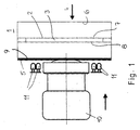
- the EC mirror glass 1 shows an EC mirror glass 1 for interior rear-view mirrors of motor vehicles.
- the EC mirror glass 1 has approximately half the thickness Recording room 2 for an EC liquid 3.
- the driver of the motor vehicle looks in the direction of arrow 4 at the mirror glass 1.
- the interference mirror layer 5 advantageously extends over the entire Back of the EC mirror glass 1. Because of the described
- the structure of the EC mirror glass has four sides 6 to 9.
- the interference mirror layer 5 is on the side 9 of the EC mirror glass facing away from the driver intended.
- a camera 10 which is advantageous is a CCD or CMOS camera. With this camera 10 Recording of video images possible.
- the lighting illuminants 11 are not sufficient for the camera 10 provided that are advantageous LEDs.
- the illuminants 11 are in one Provide sufficient number for the lighting and send a wavelength for which the EC mirror glass 1 is sufficient is transparent and for which the camera 10 used is a has sufficient sensitivity. Depending on the lighting conditions The illuminants 11 can be switched on in order to provide optimally illuminated ones Get video images.
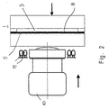
- Fig. 2 shows the possibility of the interference mirror layer 5 on the to provide third side 8 in direct contact with the EC liquid 3. Since the interference mirror layer 5 is not on the back of the EC mirror glass 1, it forms a front interference mirror layer. Otherwise, the EC mirror glass 1 and the Camera 10 and the illuminants 11 are the same as in the previous one Embodiment.
- the mirror glass 12 according to 3 has only two sides, namely that facing the driver Front 13 and the back 14.
- the interference mirror layer 5 can optionally on the front 13 or on the back 14 be provided.
- the driver looks again in the direction of arrow 4 on the mirror glass 12.
- the camera 10 is behind the mirror glass 12 directed in the direction of arrow 15.
- a CCD or CMOS camera his.
- the illuminants 11 can be provided which also correspond to the previous exemplary embodiments on the side facing away from the driver's gaze direction 4 Mirror glass 12 are located.
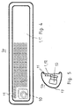
- FIG. 4 and 5 show an interior rearview mirror 16 with a Mirror housing 17, in the open front of which the mirror glass 1 or 12 is inserted.
- the camera 10 is located behind the mirror glass 1, 12 in the lower left corner of the rectangular view Interior rearview mirror 16.
- the camera 10 can, like FIG. 5 shows, be arranged slightly inclined downwards.
- Behind the mirror glass 1, 12 are the illuminants 11, which according to FIG Rows are arranged side by side and one above the other. You are beneficial except for the area of the camera 10, over the entire back the mirror glass 1, 12 provided.
- the arrangement according to FIG. 4 and 5 is advantageous if a conventional mirror glass 12 is used for the interior rearview mirror 16.
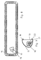
- the edge area 18 consists of a Plastic that is transparent to the IR rays of the illuminants 11, in the part of the electromagnetic part that is visible to the human eye Spectrum is opaque. This ensures that the driver or the vehicle occupants illuminants 11 don't notice. Otherwise, the interior rearview mirror 16 is the same formed as in the embodiment of FIGS. 4 and 5.
- the camera 10 can be placed anywhere behind the mirror glass 1, 12 may be arranged. It is intended to be used for the necessary field of view is covered. Since other rearview mirrors, such as garage door openers, EC electronics, memory drive and the like arranged are, the camera 10 is arranged so that the function of these devices is not affected.
- additional lighting outside the interior rearview mirror 16 can be provided.
- additional lighting can be used in the Rear light and / or ceiling light and / or reading light for the rear vehicle occupants can be integrated into cars and / or buses. It is also possible to use the additional lighting in the A-, B-, C- or D-pillar or any other pillar in the motor vehicle accommodate.
- an image transmitting device can also be attached to the camera 10 Fiber bundles 19 (Fig. 8 and 9) are connected.
- the optics of these fiber bundles 19 have diameters down to in the order of 1 mm.
- the camera 10 can to the previous embodiments without a direct view in the Vehicle interior can be housed in the mirror housing 17.
- the image is created by means of optics 20 on the head of the fiber bundle 19 captured and to the light sensitive surfaces of the camera 10 headed.
- the optical head 20 is preferably in an opening 21 in the Mirror frame 18 housed.
- the lamps 11 are as in 6 and 7 in the edge region 18 of the Mirror housing 17 is provided.
- the infrared transmit LEDs 11 are according to the previous embodiment over the entire The circumference of the edge region 18 of the mirror housing 17 is uniform distributed.
- the optical head 20 of the fiber bundle 19 behind the infrared transparent Mirror glass 1, 12 is arranged. Since the mirror glass 1, 12 for the human eye is opaque, the camera 10 and that Fiber bundles 19 not recognizable by the vehicle occupants. Furthermore the interior rearview mirror 16 is of the same design as the embodiment 8 and 9.
- the infrared transmission LEDs 11 are arranged in rows behind the mirror glass 1, 12 and arranged one below the other.
- the illuminants 11 are advantageous evenly over the entire back of the mirror glass 1, 12 distributed.
- LEDs 11 may be a residual light amplifier tube 22 (Fig. 14 and 15) be integrated into the camera optics.
- the residual light amplifier tube 22 forms an image intensifier tube or image converter height, which is also extremely bad lighting conditions a safe observation of the vehicle interior in the visible and near infrared wavelength range enables.
- the camera 10 is behind the mirror glass 1, 12 housed in the mirror housing 16. Depending on the application the camera 10 arranged in the mirror housing 17 so that it for the necessary field of view is covered.
- the camera 10 can be used for a wide variety of applications become. For example, it can be used for driver identification Driver condition monitoring, for occupant detection and occupant position, for airbag control, theft monitoring and the like be used. For example, it is possible Connect camera 10 to the vehicle electronics so that the vehicle can only be started if the authorized driver sits behind the wheel of the motor vehicle. It is also possible for example, trigger a warning signal if the driver is behind the wheel should fall asleep.
Abstract
Die Überwachungseinrichtung hat ein Spiegelglas (1), hinter dem eine Kamera (10) angeordnet ist. Um die Überwachungseinrichtung so auszubilden, daß die Kamera (10) hinter dem Spiegelglas (1) nicht sichtbar ist, das Spiegelglas (1) aber dennoch seine Funktion einwandfrei erfüllen kann, weist das Spiegelglas (1) eine im sichtbaren Spektralbereich reflektierend wirkende Spiegelschicht (5) auf, hinter der die Kamera (10) angeordnet ist. Dadurch ist die Kamera (10) hinter dem Spiegelglas (1) nicht sichtbar, während das Spiegelglas (1) die gewünschte hohe Reflexion aufweist. <IMAGE>The monitoring device has a mirror glass (1), behind which a camera (10) is arranged. In order to design the monitoring device in such a way that the camera (10) is not visible behind the mirror glass (1), but the mirror glass (1) can nevertheless function properly, the mirror glass (1) has a mirror layer (5) that has a reflective effect in the visible spectral range ) behind which the camera (10) is arranged. As a result, the camera (10) is not visible behind the mirror glass (1) while the mirror glass (1) has the desired high reflection. <IMAGE>
Description
Die Erfindung betrifft eine Überwachungseinrichtung für Fahrzeuge,
vorzugsweise für Kraftfahrzeuge, nach dem Oberbegriff des Anspruches
1.The invention relates to a monitoring device for vehicles,
preferably for motor vehicles, according to the preamble of the
Es sind Innenrückblickspiegel von Kraftfahrzeugen bekannt, die mit einer Kamera ausgestattet sind. Damit er seine Funktion erfüllen kann, ist das Spiegelglas mit einer Aussparung versehen. Aus ästhetischen Gründen sind jedoch Aussparungen in der Reflexionsschicht von Spiegelgläsern nicht gern gesehen. Oft soll die Kamera auch unsichtbar bleiben. In der Automobilindustrie bestehen zudem Vorschriften, die sich auf die geometrischen Ausmaße der Spiegelfläche beziehen.Interior rear-view mirrors of motor vehicles are known, which with are equipped with a camera. So that it can fulfill its function the mirror glass is provided with a recess. For aesthetic reasons However, there are recesses in the reflective layer for reasons disliked by mirror glasses. Often the camera should also be invisible stay. There are also in the automotive industry Regulations that relate to the geometric dimensions of the Get mirror surface.
Der Erfindung liegt die Aufgabe zugrunde, die gattungsgemäße Überwachungseinrichtung so auszubilden, daß die Kamera hinter dem Spiegelglas nicht sichtbar ist, das Spiegelglas aber dennoch seine Funktion einwandfrei erfüllen kann.The invention has for its object the generic Train the monitoring device so that the camera is behind the mirror glass is not visible, but the mirror glass is nevertheless can perform its function perfectly.
Diese Aufgabe wird bei der gattungsgemäßen Überwachungseinrichtung
erfindungsgemäß mit den kennzeichnenden Merkmalen des Anspruches
1 gelöst. This task is carried out in the generic monitoring device
according to the invention with the characterizing features of the
Bei der erfindungsgemäßen Überwachungseinrichtung liegt die Kamera hinter der Spiegelschicht, die im sichtbaren Spektralbereich vorzugsweise bis 50 % reflektierend ausgebildet ist. Dadurch ist die Kamera hinter dem Spiegelglas nicht sichtbar, während das Spiegelglas die gewünschte hohe Reflexion aufweist. Wird das Spiegelglas beispielsweise in einem Innenrückblickspiegel eines Kraftfahrzeuges verwendet, hat die Spiegelschicht ein Reflexionsspektrum, das zu einem Mindestprozentsatz, wie es in den Automobilspiegelvorschriften vorgeschrieben ist, Licht reflektiert. Vorteilhaft ist die Kamera eine CCD- oder CMOS-Kamera. Das Spiegelglas mit der Spiegelschicht ist im nahen Infrarotbereich ausreichend transparent, so daß mit einer solchen Kamera Videobilder aufgenommen werden können. Für den Fall, daß die Beleuchtung nicht ausreichend ist, kann mit einer Zusatzbeleuchtung, vorzugsweise mit LEDs, die eine Wellenlänge aussenden, für welche die Spiegelschicht ausreichend transparent ist und für welche die Kamera eine ausreichende Empfindlichkeit besitzt, zusätzlich beleuchtet werden. Durch beispielsweise Schieben des transparenten Spektralbereiches des Spiegelglases entlang der Wellenlängenachse derart, daß die Transmission einen maximalen Wert annimmt und gleichzeitig das Empfindlichkeitsmaximum der CCD- oder CMOS-Kamera abdeckt, kann bei schlechten Lichtverhältnissen im sichtbaren Bereich, unbemerkt durch das menschliche Auge, der erforderliche Bereich zusätzlich beleuchtet werden. Die Zusatzbeleuchtung wird vorteilhaft durch Infrarot-LEDs gebildet, die Licht in einem Wellenlängenbereich aussenden, der im Transmissionsbereich der Spiegelschicht liegt und für den die Kamera die geforderte Empfindlichkeit aufweist.The camera is located in the monitoring device according to the invention behind the mirror layer, which is in the visible spectral range is preferably up to 50% reflective. This is the Camera behind the mirror glass is not visible while the mirror glass has the desired high reflection. Will the mirror glass for example in an interior rear view mirror of a motor vehicle used, the mirror layer has a reflection spectrum that too a minimum percentage as stated in the automotive mirroring regulations is prescribed, reflected light. The camera is advantageous CCD or CMOS camera. The mirror glass with the mirror layer is sufficiently transparent in the near infrared range so that video images can be recorded with such a camera. In the event that the lighting is insufficient, a Additional lighting, preferably with LEDs that have a wavelength for which the mirror layer is sufficiently transparent and for which the camera has sufficient sensitivity, are additionally illuminated. For example, by pushing of the transparent spectral range of the mirror glass along the Wavelength axis such that the transmission has a maximum Value and at the same time the sensitivity maximum of CCD or CMOS camera can cover in low light conditions in the visible area, unnoticed by the human eye, the required area should also be illuminated. The additional lighting is advantageously formed by infrared LEDs, which Send out light in a wavelength range that is in the transmission range the mirror layer and for which the camera is the required Has sensitivity.
Die Kamera ist vorteilhaft an die Stromversorgung des Fahrzeuges angeschlossen. Die von ihr aufgenommenen Videobilder können in einem Monitor dargestellt werden. Es ist aber auch möglich, die Videobilder auf einem Speichermedium, beispielsweise einem Videoband, einer Festplatte oder dergleichen zu speichern. Es ist auch möglich, gleichzeitig das aufgenommene Bild zu speichern und im Monitor darzustellen.The camera is advantageous to the power supply of the vehicle connected. The video images captured by her can be in be displayed on a monitor. But it is also possible to view the video images on a storage medium, for example a video tape, a hard drive or the like. It is also possible to save the captured image at the same time and in Display monitor.
Weitere Merkmale der Erfindung ergeben sich aus den weiteren Ansprüchen, der Beschreibung und den Zeichnungen.Further features of the invention result from the further claims, the description and the drawings.
Die Erfindung wird anhand einiger in den Zeichnungen dargestellter Ausführungsbeispiele näher erläutert. Es zeigen
- Fig. 1
- in Seitenansicht und in schematischer Darstellung eine erfindungsgemäße Vorrichtung,
- Fig. 2
- in einer Darstellung entsprechend Fig. 1 eine zweite Ausführungsform einer erfindungsgemäßen Vorrichtung,
- Fig. 3
- in einer Darstellung entsprechend Fig. 1 eine dritte Ausführungsform einer erfindungsgemäßen Vorrichtung,
- Fig. 4
- eine Ansicht eines für ein Kraftfahrzeug vorgesehenen Innenrückblickspiegels, in dem eine erfindungsgemäße Vorrichtung untergebracht ist,
- Fig. 5
- in schematischer Darstellung einen Schnitt durch den Innenrückblickspiegel gemäß Fig. 4,
- Fig. 6 bis Fig. 15
- jeweils in Darstellungen entsprechend den Fig. 4 und 5 unterschiedlich ausgebildete Innenrückblickspiegel von Kraftfahrzeugen.
- Fig. 1
- a side view and a schematic representation of a device according to the invention,
- Fig. 2
- 1 shows a second embodiment of a device according to the invention,
- Fig. 3
- 1 shows a third embodiment of a device according to the invention,
- Fig. 4
- 1 shows a view of an interior rearview mirror provided for a motor vehicle, in which a device according to the invention is accommodated,
- Fig. 5
- a schematic representation of a section through the interior rear view mirror according to FIG. 4,
- 6 to 15
- 4 and 5 differently designed interior rear view mirrors of motor vehicles in each case in representations corresponding to FIGS.
Fig. 1 zeigt ein EC-Spiegelglas 1 für Innenrückblickspiegel von Kraftfahrzeugen.
Das EC-Spiegelglas 1 weist etwa in halber Dicke einen
Aufnahmeraum 2 für eine EC-Flüssigkeit 3 auf. Der Fahrer des Kraftfahrzeuges
blickt in Richtung des Pfeiles 4 auf das Spiegelglas 1. An
der vom Fahrer abgewandten Rückseite des EC-Spiegelglases 1 befindet
sich eine Rückseiteninterferenzspiegelschicht 5. Die Interferenzspiegelschicht
5 erstreckt sich vorteilhaft über die gesamte
Rückseite des EC-Spiegelglases 1. Aufgrund des beschriebenen
Aufbaus hat das EC-Spiegelglas vier Seiten 6 bis 9. Die Interferenzspiegelschicht
5 ist an der vom Fahrer abgewandten Seite 9 des EC-Spiegelglases
vorgesehen.1 shows an
Hinter dem EC-Spiegelglas befindet sich eine Kamera 10, die vorteilhaft
eine CCD- oder CMOS-Kamera ist. Mit dieser Kamera 10 ist die
Aufnahme von Videobildern möglich. Für den Fall, daß die Beleuchtung
für die Kamera 10 nicht ausreichen sollte, sind Leuchtmittel 11
vorgesehen, die vorteilhaft LEDs sind. Die Leuchtmittel 11 sind in einer
für die Beleuchtung ausreichenden Anzahl vorgesehen und senden
eine Wellenlänge aus, für welche das EC-Spiegelglas 1 ausreichend
transparent ist und für welche die verwendete Kamera 10 eine
ausreichende Empfindlichkeit besitzt. Je nach den Lichtverhältnissen
können die Leuchtmittel 11 zugeschaltet werden, um optimal ausgeleuchtete
Videobilder zu erhalten.Behind the EC mirror glass is a
Fig. 2 zeigt die Möglichkeit, die Interferenzspiegelschicht 5 auf der
dritten Seite 8 in direktem Kontakt zur EC-Flüssigkeit 3 vorzusehen.
Da die Interferenzspiegelschicht 5 nicht an der Rückseite des EC-Spiegelglases
1 vorgesehen ist, bildet sie eine Vorderseiteninterferenzspiegelschicht.
Im übrigen sind das EC-Spiegelglas 1 sowie die
Kamera 10 und die Leuchtmittel 11 gleich ausgebildet wie beim vorigen
Ausführungsbeispiel.Fig. 2 shows the possibility of the
Fig. 3 zeigt die Möglichkeit, die Kamera 10 auch dann einzusetzen,
wenn kein EC-Spiegelglas vorhanden ist. Das Spiegelglas 12 gemäß
Fig. 3 hat lediglich zwei Seiten, nämlich die dem Fahrer zugewandte
Vorderseite 13 sowie die Rückseite 14. Die Interferenzspiegelschicht
5 kann wahlweise an der Vorderseite 13 oder an der Rückseite 14
vorgesehen sein. Der Fahrer blickt wieder in Richtung des Pfeiles 4
auf das Spiegelglas 12. Die Kamera 10 hinter dem Spiegelglas 12 ist
in Richtung des Pfeiles 15 gerichtet. Sie kann entsprechend den
beiden vorigen Ausführungsbeispielen eine CCD- oder CMOS-Kamera
sein. Zusätzlich können die Leuchtmittel 11 vorgesehen werden,
die sich entsprechend den vorigen Ausführungsbeispielen ebenfalls
auf der von der Fahrerblickrichtung 4 abgewandten Seite des
Spiegelglases 12 befinden.3 shows the possibility of using the
Die Fig. 4 und 5 zeigen einen Innenrückblickspiegel 16 mit einem
Spiegelgehäuse 17, in dessen offener Vorderseite das Spiegelglas 1
oder 12 eingesetzt ist. Die Kamera 10 befindet sich hinter dem Spiegelglas
1, 12 in der linken unteren Ecke des in Ansicht rechteckförmigen
Innenrückblickspiegels 16. Die Kamera 10 kann, wie Fig. 5
zeigt, leicht nach unten geneigt angeordnet sein. Hinter dem Spiegelglas
1, 12 befinden sich die Leuchtmittel 11, die gemäß Fig. 4 in
Reihen neben- und übereinander angeordnet sind. Sie sind vorteilhaft,
bis auf den Bereich der Kamera 10, über die gesamte Rückseite
des Spiegelglases 1, 12 vorgesehen. Die Anordnung gemäß den Fig.
4 und 5 ist dann vorteilhaft, wenn ein herkömmliches Spiegelglas 12
für den Innenrückblickspiegel 16 verwendet wird.4 and 5 show an interior
Hat der Innenrückblickspiegel 16 das EC-Spiegelglas 1 (Fig. 6 und
7), werden die Leuchtmittel 11, die entsprechend den vorhergehenden
Ausführungsformen Infrarot-Sende-LEDs sind, vorteilhaft im
Randbereich 18 des Spiegelgehäuses 17 angeordnet. Wenn eine
herkömmliche Titan- bzw. Chrom- bzw. Titan-Chromschicht als Spiegelschicht
verwendet werden soll, kann die Transmission zusammen
mit der abgedunkelten EC-Schicht bereits so gering werden, daß die
zusätzliche Beleuchtung notwendig werden kann. Es wird vorteilhaft
eine Infrarot-Beleuchtung im Spektralbereich der Kameraempfindlichkeit
gewählt. Da die Verluste durch das zweimalige Durchdringen der
Spiegelschicht und der EC-Schicht 3 (Fig. 1) zu groß werden, sind
die Infrarot-Sende-LEDs vorteilhaft im Randbereich 18 des Spiegelgehäuses
17 untergebracht. Der Randbereich 18 besteht aus einem
Kunststoff, der für die IR-Strahlen der Leuchtmittel 11 durchlässig ist,
im für das menschliche Auge sichtbaren Teil des elektromagnetischen
Spektrums hingegen undurchsichtig ist. Dadurch ist gewährleistet,
daß der Fahrer oder die Fahrzeuginsassen die Leuchtmittel 11
nicht bemerken. Im übrigen ist der Innenrückblickspiegel 16 gleich
ausgebildet wie bei der Ausführungsform nach den Fig. 4 und 5.Has the interior
Die Kamera 10 kann an einer beliebigen Stelle hinter dem Spiegelglas
1, 12 angeordnet sein. Sie wird so vorgesehen, daß sie den für
den jeweiligen Verwendungszweck notwendigen Sichtbereich erfaßt.
Da in Innenrückblickspiegeln häufig weitere Einrichtungen, wie Garagentoröffner,
EC-Elektronik, Memoryantrieb und dergleichen angeordnet
sind, wird die Kamera 10 so angeordnet, daß die Funktion
dieser Vorrichtungen nicht beeinträchtigt wird.The
Bei den beschriebenen und noch zu erläuternden Ausführungsformen
kann entsprechend den räumlichen Verhältnissen im Kraftfahrzeug
eine Zusatzbeleuchtung außerhalb des Innenrückblickspiegels 16
vorgesehen sein. So kann eine solche Zusatzbeleuchtung in die
Fondleuchte und/oder Deckenleuchte und/oder Leseleuchte für die
hinteren Fahrzeuginsassen in PKWs und/oder Bussen integriert werden.
Es ist auch möglich, die Zusatzbeleuchtung in der A-, B-, C-
oder D-Säule oder einer beliebigen weiteren Säule im Kraftfahrzeug
unterzubringen.In the described and still to be explained embodiments
can according to the spatial conditions in the motor vehicle
additional lighting outside the interior
In besonderen Einsatzfällen kann an die Kamera 10 auch ein bildübertragendes
Faserbündel 19 (Fig. 8 und 9) angeschlossen werden.
Die Optiken dieser Faserbündel 19 haben Durchmesser bis hinunter
in die Größenordnung von 1 mm. Die Kamera 10 kann im Gegensatz
zu den vorigen Ausführungsbeispielen ohne direkte Sicht in den
Fahrzeuginnenraum im Spiegelgehäuse 17 untergebracht werden.
Das Bild wird mittels einer Optik 20 am Kopf des Faserbündels 19
eingefangen und zu den lichtempfindlichen Flächen der Kamera 10
geleitet. Der Optikkopf 20 ist vorzugsweise in einer Öffnung 21 im
Spiegelrahmen 18 untergebracht. Die Leuchtmittel 11 sind wie bei
der Ausführungsform gemäß den Fig. 6 und 7 im Randbereich 18 des
Spiegelgehäuses 17 vorgesehen. Die Infrarot-Sende-LEDs 11 sind
entsprechend dem vorigen Ausführungsbeispiel über den gesamten
Umfang des Randbereiches 18 des Spiegelgehäuses 17 gleichmäßig
verteilt angeordnet.In special applications, an image transmitting device can also be attached to the
Die Fig. 10 und 11 zeigen eine Ausführungsform, bei welcher der Optikkopf
20 des Faserbündels 19 hinter dem infrarotdurchlässigen
Spiegelglas 1, 12 angeordnet ist. Da das Spiegelglas 1, 12 für das
menschliche Auge undurchsichtig ist, sind die Kamera 10 und das
Faserbündel 19 von den Fahrzeuginsassen nicht zu erkennen. Im übrigen
ist der Innenrückblickspiegel 16 gleich ausgebildet wie die Ausführungsform
nach den Fig. 8 und 9.10 and 11 show an embodiment in which the
Die Fig. 12 und 13 zeigen einen Innenrückblickspiegel 16, bei dem
der Optikkopf 20 des Faserbündels 19 entsprechend der vorigen Ausführungsform
hinter dem Spiegelglas 1, 12 angeordnet ist. Die Infrarot-Sende-LEDs
11 sind hinter dem Spiegelglas 1, 12 in Reihen über-
und untereinander angeordnet. Vorteilhaft sind die Leuchtmittel 11
über die gesamte Rückseite des Spiegelglases 1, 12 gleichmäßig
verteilt angeordnet.12 and 13 show an interior
Als Alternative zur aktiven Beleuchtung mittels der Infrarot-Sende-LEDs
11 kann eine Restlichtverstärkerröhre 22 (Fig. 14 und 15) vor
der Kameraoptik integriert sein. Die Restlichtverstärkerröhre 22 bildet
eine Bildverstärkerröhre bzw. Bildwandlerröhe, die auch bei extrem
schlechten Lichtverhältnissen eine sichere Beobachtung des Fahrzeuginnenraumes
im sichtbaren und im nahen infraroten Wellenlängenbereich
ermöglicht. Die Kamera 10 ist hinter dem Spiegelglas 1,
12 im Spiegelgehäuse 16 untergebracht. Je nach Einsatzzweck wird
die Kamera 10 so im Spiegelgehäuse 17 angeordnet, daß sie den für
den jeweiligen Verwendungszweck notwendigen Sichtbereich erfaßt.As an alternative to active lighting using the
Damit von der Kamera 10 vom Fahrzeuginnenraum aus nichts zu sehen
ist, ist bei den beschriebenen Ausführungsformen die Rückseite
des Spiegelglases 1, 12, mit Ausnahme der Öffnung 21 für den Optikkopf
20 des Faserbündels 19 (Fig. 8 und 9), mit einem schwarzen
Lack überzogen. Für den Fall, daß die Infrarot-Zusatzbeleuchtung 11
hinter dem Spiegelglas 1, 12 verwendet wird, ist der Lack für infrarotes
Licht mit der jeweiligen Wellenlänge transparent, im sichtbaren
Wellenlängenbereich undurchsichtig. Die Optik ist entspiegelt und
von hinten sowie von der Seite her lichtdicht auf der Rückseite des
Spiegelglases 1, 12 so befestigt, daß seitliches Streulicht durch die
Spiegelschicht nicht eindringen und vom Endbenutzer, beispielsweise
dem Fahrer, nicht gesehen werden kann.So that nothing can be seen from the
Die Kamera 10 kann für die unterschiedlichsten Anwendungen eingesetzt
werden. So kann sie beispielsweise zur Fahreridentifikation, zur
Fahrerzustandsüberwachung, zur Insassenerkennung und Insassenposition,
zur Airbagsteuerung, zur Diebstahlüberwachung und dergleichen
eingesetzt werden. So ist es beispielsweise möglich, die
Kamera 10 mit der Fahrzeugelektrik so zu verbinden, daß das Fahrzeug
nur dann in Gang gesetzt werden kann, wenn der befugte Fahrer
hinter dem Steuer des Kraftfahrzeuges sitzt. Es ist weiter möglich,
beispielsweise ein Warnsignal auszulösen, falls der Fahrer am Steuer
einschlafen sollte.The
Claims (12)
dadurch gekennzeichnet, daß das Spiegelglas (1, 12) eine im sichtbaren Spektralbereich reflektierend wirkende Spiegelschicht (5) aufweist, hinter der die Kamera (10) angeordnet ist.Monitoring device for vehicles, preferably for motor vehicles, with at least one mirror glass, behind which at least one camera is arranged,
characterized in that the mirror glass (1, 12) has a mirror layer (5) with a reflective effect in the visible spectral range, behind which the camera (10) is arranged.
dadurch gekennzeichnet, daß die Spiegelschicht (5) eine Interferenzspiegelschicht, eine Chromspiegelschicht oder eine Titan-Chrom-Spiegelschicht ist.Monitoring device according to claim 1,
characterized in that the mirror layer (5) is an interference mirror layer, a chrome mirror layer or a titanium-chrome mirror layer.
dadurch gekennzeichnet, daß das Spiegelglas (1) ein EC-Spiegelglas oder ein herkömmliches Spiegelglas ist.Monitoring device according to claim 1 or 2,
characterized in that the mirror glass (1) is an EC mirror glass or a conventional mirror glass.
dadurch gekennzeichnet, daß das EC-Spiegelglas (1) eine EC-Schicht (3) aufweist, hinter der die Spiegelschicht (5) vorgesehen ist.Monitoring device according to claim 3,
characterized in that the EC mirror glass (1) has an EC layer (3) behind which the mirror layer (5) is provided.
dadurch gekennzeichnet, daß der Kamera (10) eine Zusatzbeleuchtung (11) zugeordnet ist, die vorteilhaft Licht in einer Wellenlänge aussendet, für welche die Spiegelschicht (5) durchlässig ist.Monitoring device according to one of claims 1 to 4,
characterized in that the camera (10) is assigned additional lighting (11) which advantageously emits light at a wavelength for which the mirror layer (5) is transparent.
dadurch gekennzeichnet, daß die Zusatzbeleuchtung (11) Licht außerhalb des sichtbaren Spektrums aussendet.Monitoring device according to claim 5,
characterized in that the additional lighting (11) emits light outside the visible spectrum.
dadurch gekennzeichnet, daß die vorteilhaft hinter der Spiegelschicht (5) angeordnete Zusatzbeleuchtung (11) durch LEDs, vorzugsweise durch Infrarot-Sende-LEDs, gebildet ist.Monitoring device according to claim 5 or 6,
characterized in that the additional lighting (11) advantageously arranged behind the mirror layer (5) is formed by LEDs, preferably by infrared transmitter LEDs.
dadurch gekennzeichnet, daß die Zusatzbeleuchtung (11) durch in Reihen neben- und untereinander angeordnete LEDs gebildet ist, die vorteilhaft im vorzugsweise aus für das menschliche Auge undurchsichtigem Material bestehenden Randbereich (18) eines Gehäuses (19) eines Innenrückblickspiegels (16) angeordnet sind.Monitoring device according to one of claims 5 to 7,
characterized in that the additional lighting (11) is formed by LEDs arranged in rows next to and below one another, which are advantageously arranged in the edge region (18) of a housing (19) of an interior rear view mirror (16), which is preferably made of opaque material for the human eye.
dadurch gekennzeichnet, daß an die Kamera (10) ein bildübertragendes Faserbündel (19) angeschlossen ist.Monitoring device according to one of claims 1 to 8,
characterized in that an image-transmitting fiber bundle (19) is connected to the camera (10).
dadurch gekennzeichnet, daß das bildübertragende Faserbündel (19) mit einem Optikkopf (20) an der Rückseite des Spiegelglases (1, 20) anliegt.Monitoring device according to claim 9,
characterized in that the image-transmitting fiber bundle (19) rests with an optical head (20) on the back of the mirror glass (1, 20).
dadurch gekennzeichnet, daß das bildübertragende Faserbündel (19) mit einem Optikkopf (20) im Randbereich (18) des Spiegelgehäuses (16) angeordnet ist.Monitoring device according to claim 9,
characterized in that the image-transmitting fiber bundle (19) is arranged with an optical head (20) in the edge region (18) of the mirror housing (16).
dadurch gekennzeichnet, daß die Kamera (10) mit einem vorteilhaft im Bereich hinter dem Spiegelglas (1, 20) angeordneten Restlichtverstärker (22) ausgestattet ist.Monitoring device according to one of claims 1 to 11,
characterized in that the camera (10) is equipped with a residual light amplifier (22) which is advantageously arranged in the area behind the mirror glass (1, 20).
Applications Claiming Priority (2)
| Application Number | Priority Date | Filing Date | Title |
|---|---|---|---|
| DE10003643 | 2000-01-28 | ||
| DE10003643A DE10003643A1 (en) | 2000-01-28 | 2000-01-28 | Surveillance device for automobile uses camera behind mirror glass which reflects light in visible wavelength spectrum |
Publications (3)
| Publication Number | Publication Date |
|---|---|
| EP1120313A2 true EP1120313A2 (en) | 2001-08-01 |
| EP1120313A3 EP1120313A3 (en) | 2003-12-03 |
| EP1120313B1 EP1120313B1 (en) | 2007-08-22 |
Family
ID=7628990
Family Applications (1)
| Application Number | Title | Priority Date | Filing Date |
|---|---|---|---|
| EP01101569A Expired - Lifetime EP1120313B1 (en) | 2000-01-28 | 2001-01-25 | Monitoring device for a vehicle, preferably a motor vehicle |
Country Status (3)
| Country | Link |
|---|---|
| US (1) | US6703925B2 (en) |
| EP (1) | EP1120313B1 (en) |
| DE (2) | DE10003643A1 (en) |
Cited By (4)
| Publication number | Priority date | Publication date | Assignee | Title |
|---|---|---|---|---|
| US7548803B2 (en) * | 2004-01-21 | 2009-06-16 | Maccarthy James | Vehicle surveillance and control system |
| EP2025556A3 (en) * | 2007-08-07 | 2011-03-23 | Murakami Corporation | Image pickup device-equipped rear view mirror |
| CN105339216A (en) * | 2014-05-16 | 2016-02-17 | 赵少敏 | Concealed human face identification monitoring device |
| CN105667393A (en) * | 2016-03-22 | 2016-06-15 | 盐城工业职业技术学院 | Intelligent running auxiliary barrier-avoiding system and intelligent running auxiliary barrier-avoiding method |
Families Citing this family (148)
| Publication number | Priority date | Publication date | Assignee | Title |
|---|---|---|---|---|
| US5877897A (en) | 1993-02-26 | 1999-03-02 | Donnelly Corporation | Automatic rearview mirror, vehicle lighting control and vehicle interior monitoring system using a photosensor array |
| US6822563B2 (en) | 1997-09-22 | 2004-11-23 | Donnelly Corporation | Vehicle imaging system with accessory control |
| US6891563B2 (en) | 1996-05-22 | 2005-05-10 | Donnelly Corporation | Vehicular vision system |
| US20070154063A1 (en) * | 1995-06-07 | 2007-07-05 | Automotive Technologies International, Inc. | Image Processing Using Rear View Mirror-Mounted Imaging Device |
| US7655894B2 (en) | 1996-03-25 | 2010-02-02 | Donnelly Corporation | Vehicular image sensing system |
| US6882287B2 (en) | 2001-07-31 | 2005-04-19 | Donnelly Corporation | Automotive lane change aid |
| US7697027B2 (en) | 2001-07-31 | 2010-04-13 | Donnelly Corporation | Vehicular video system |
| JP3686896B2 (en) * | 2002-03-29 | 2005-08-24 | 弘 杉浦 | Criminal index device for stolen vehicles |
| US20040252993A1 (en) * | 2002-04-05 | 2004-12-16 | Hidenori Sato | Camera built-in mirror equipment |
| ES2391556T3 (en) | 2002-05-03 | 2012-11-27 | Donnelly Corporation | Object detection system for vehicles |
| JP4088100B2 (en) * | 2002-05-14 | 2008-05-21 | 株式会社村上開明堂 | Rearview mirror with built-in camera |
| DE50207570D1 (en) * | 2002-08-29 | 2006-08-31 | Braun Uwe Peter | Device for monitoring and influencing the alertness of a vehicle driver |
| ES2212733B1 (en) * | 2002-10-18 | 2005-05-01 | Jose Muñoz Leo | SYSTEM OF VISUALIZATION OF IMAGES OF THE MARINE FUND. |
| US20040140885A1 (en) * | 2003-01-17 | 2004-07-22 | Slicker James M. | Vehicle security system |
| US7308341B2 (en) | 2003-10-14 | 2007-12-11 | Donnelly Corporation | Vehicle communication system |
| US7526103B2 (en) | 2004-04-15 | 2009-04-28 | Donnelly Corporation | Imaging system for vehicle |
| US20050243172A1 (en) * | 2004-04-30 | 2005-11-03 | Teiichiro Takano | Rear view mirror with built-in camera |
| GB2415036A (en) * | 2004-06-09 | 2005-12-14 | Johnson William N H | Security device |
| US7881496B2 (en) | 2004-09-30 | 2011-02-01 | Donnelly Corporation | Vision system for vehicle |
| US7720580B2 (en) | 2004-12-23 | 2010-05-18 | Donnelly Corporation | Object detection system for vehicle |
| US8547432B1 (en) * | 2005-03-23 | 2013-10-01 | Jerald A. Hairford | Surveillance system |
| ATE517368T1 (en) | 2005-05-16 | 2011-08-15 | Donnelly Corp | VEHICLE MIRROR ARRANGEMENT WITH CHARACTER ON THE REFLECTIVE PART |
| US7334924B2 (en) | 2005-06-09 | 2008-02-26 | Delphi Technologies, Inc. | Illumination apparatus for an optical occupant monitoring system in a vehicle |
| US7859392B2 (en) | 2006-05-22 | 2010-12-28 | Iwi, Inc. | System and method for monitoring and updating speed-by-street data |
| US9067565B2 (en) | 2006-05-22 | 2015-06-30 | Inthinc Technology Solutions, Inc. | System and method for evaluating driver behavior |
| WO2008024639A2 (en) | 2006-08-11 | 2008-02-28 | Donnelly Corporation | Automatic headlamp control system |
| JP5122782B2 (en) * | 2006-09-19 | 2013-01-16 | 株式会社デンソー | Mounting structure for vehicle driver's camera |
| US7899610B2 (en) | 2006-10-02 | 2011-03-01 | Inthinc Technology Solutions, Inc. | System and method for reconfiguring an electronic control unit of a motor vehicle to optimize fuel economy |
| FR2907300B1 (en) * | 2006-10-16 | 2009-04-17 | Sagem Defense Securite | MONITORING INSTALLATION |
| US8013780B2 (en) | 2007-01-25 | 2011-09-06 | Magna Electronics Inc. | Radar sensing system for vehicle |
| ITPR20070006A1 (en) * | 2007-02-08 | 2008-08-09 | Techimp S P A | PROCEDURE FOR PROCESSING DATA RELATING TO A PARTIAL ELECTRICAL DISCHARGE ACTIVITY |
| US8825277B2 (en) | 2007-06-05 | 2014-09-02 | Inthinc Technology Solutions, Inc. | System and method for the collection, correlation and use of vehicle collision data |
| US8666590B2 (en) | 2007-06-22 | 2014-03-04 | Inthinc Technology Solutions, Inc. | System and method for naming, filtering, and recall of remotely monitored event data |
| US9129460B2 (en) | 2007-06-25 | 2015-09-08 | Inthinc Technology Solutions, Inc. | System and method for monitoring and improving driver behavior |
| US7999670B2 (en) * | 2007-07-02 | 2011-08-16 | Inthinc Technology Solutions, Inc. | System and method for defining areas of interest and modifying asset monitoring in relation thereto |
| US7914187B2 (en) | 2007-07-12 | 2011-03-29 | Magna Electronics Inc. | Automatic lighting system with adaptive alignment function |
| US8818618B2 (en) | 2007-07-17 | 2014-08-26 | Inthinc Technology Solutions, Inc. | System and method for providing a user interface for vehicle monitoring system users and insurers |
| US8577703B2 (en) * | 2007-07-17 | 2013-11-05 | Inthinc Technology Solutions, Inc. | System and method for categorizing driving behavior using driver mentoring and/or monitoring equipment to determine an underwriting risk |
| US9117246B2 (en) | 2007-07-17 | 2015-08-25 | Inthinc Technology Solutions, Inc. | System and method for providing a user interface for vehicle mentoring system users and insurers |
| US20090027497A1 (en) | 2007-07-26 | 2009-01-29 | Stephen Thomas Peacock | Camera light |
| US8017898B2 (en) | 2007-08-17 | 2011-09-13 | Magna Electronics Inc. | Vehicular imaging system in an automatic headlamp control system |
| US8451107B2 (en) * | 2007-09-11 | 2013-05-28 | Magna Electronics, Inc. | Imaging system for vehicle |
| US7876205B2 (en) * | 2007-10-02 | 2011-01-25 | Inthinc Technology Solutions, Inc. | System and method for detecting use of a wireless device in a moving vehicle |
| US8446470B2 (en) | 2007-10-04 | 2013-05-21 | Magna Electronics, Inc. | Combined RGB and IR imaging sensor |
| US20090177336A1 (en) * | 2008-01-07 | 2009-07-09 | Mcclellan Scott | System and Method for Triggering Vehicle Functions |
| JP5505761B2 (en) * | 2008-06-18 | 2014-05-28 | 株式会社リコー | Imaging device |
| US8688180B2 (en) * | 2008-08-06 | 2014-04-01 | Inthinc Technology Solutions, Inc. | System and method for detecting use of a wireless device while driving |
| US20100211301A1 (en) * | 2009-02-13 | 2010-08-19 | Mcclellan Scott | System and method for analyzing traffic flow |
| US8892341B2 (en) * | 2009-02-13 | 2014-11-18 | Inthinc Technology Solutions, Inc. | Driver mentoring to improve vehicle operation |
| US8963702B2 (en) | 2009-02-13 | 2015-02-24 | Inthinc Technology Solutions, Inc. | System and method for viewing and correcting data in a street mapping database |
| US8188887B2 (en) * | 2009-02-13 | 2012-05-29 | Inthinc Technology Solutions, Inc. | System and method for alerting drivers to road conditions |
| WO2010099416A1 (en) | 2009-02-27 | 2010-09-02 | Magna Electronics | Alert system for vehicle |
| US20100266326A1 (en) * | 2009-04-21 | 2010-10-21 | Chuang Cheng-Hua | Mark-erasable pen cap |
| US8376595B2 (en) | 2009-05-15 | 2013-02-19 | Magna Electronics, Inc. | Automatic headlamp control |
| CN102481874B (en) | 2009-07-27 | 2015-08-05 | 马格纳电子系统公司 | Parking assistance system |
| US9495876B2 (en) | 2009-07-27 | 2016-11-15 | Magna Electronics Inc. | Vehicular camera with on-board microcontroller |
| US9041806B2 (en) | 2009-09-01 | 2015-05-26 | Magna Electronics Inc. | Imaging and display system for vehicle |
| US10800329B2 (en) | 2010-04-19 | 2020-10-13 | SMR Patents S.à.r.l. | Rear view mirror simulation |
| US10703299B2 (en) | 2010-04-19 | 2020-07-07 | SMR Patents S.à.r.l. | Rear view mirror simulation |
| US9117123B2 (en) | 2010-07-05 | 2015-08-25 | Magna Electronics Inc. | Vehicular rear view camera display system with lifecheck function |
| US9900522B2 (en) | 2010-12-01 | 2018-02-20 | Magna Electronics Inc. | System and method of establishing a multi-camera image using pixel remapping |
| US20120150387A1 (en) * | 2010-12-10 | 2012-06-14 | Tk Holdings Inc. | System for monitoring a vehicle driver |
| US9264672B2 (en) | 2010-12-22 | 2016-02-16 | Magna Mirrors Of America, Inc. | Vision display system for vehicle |
| WO2012103193A1 (en) | 2011-01-26 | 2012-08-02 | Magna Electronics Inc. | Rear vision system with trailer angle detection |
| US9194943B2 (en) | 2011-04-12 | 2015-11-24 | Magna Electronics Inc. | Step filter for estimating distance in a time-of-flight ranging system |
| US9834153B2 (en) | 2011-04-25 | 2017-12-05 | Magna Electronics Inc. | Method and system for dynamically calibrating vehicular cameras |
| US9357208B2 (en) | 2011-04-25 | 2016-05-31 | Magna Electronics Inc. | Method and system for dynamically calibrating vehicular cameras |
| WO2013016409A1 (en) | 2011-07-26 | 2013-01-31 | Magna Electronics Inc. | Vision system for vehicle |
| WO2013019707A1 (en) | 2011-08-01 | 2013-02-07 | Magna Electronics Inc. | Vehicle camera alignment system |
| DE112012003931T5 (en) | 2011-09-21 | 2014-07-10 | Magna Electronics, Inc. | Image processing system for a motor vehicle with image data transmission and power supply via a coaxial cable |
| US9146898B2 (en) | 2011-10-27 | 2015-09-29 | Magna Electronics Inc. | Driver assist system with algorithm switching |
| US9071740B1 (en) | 2011-10-28 | 2015-06-30 | Google Inc. | Modular camera system |
| US9491451B2 (en) | 2011-11-15 | 2016-11-08 | Magna Electronics Inc. | Calibration system and method for vehicular surround vision system |
| WO2013081985A1 (en) | 2011-11-28 | 2013-06-06 | Magna Electronics, Inc. | Vision system for vehicle |
| WO2013086249A2 (en) | 2011-12-09 | 2013-06-13 | Magna Electronics, Inc. | Vehicle vision system with customized display |
| US9197686B1 (en) | 2012-01-06 | 2015-11-24 | Google Inc. | Backfill of video stream |
| DE102018116008B4 (en) | 2018-07-02 | 2020-07-02 | Motherson Innovations Company Limited | Basic arrangement with rearview device |
| EP3632748B1 (en) | 2018-10-04 | 2022-05-18 | Motherson Innovations Company Limited | Rear view assembly and vehicle with such rear view assembly |
| DE102018116011B4 (en) | 2018-07-02 | 2020-07-02 | Motherson Innovations Company Limited | Sealing means, basic arrangement with such a sealing means and rearview device with such a basic arrangement |
| US10457209B2 (en) | 2012-02-22 | 2019-10-29 | Magna Electronics Inc. | Vehicle vision system with multi-paned view |
| US9319637B2 (en) | 2012-03-27 | 2016-04-19 | Magna Electronics Inc. | Vehicle vision system with lens pollution detection |
| US9446713B2 (en) | 2012-09-26 | 2016-09-20 | Magna Electronics Inc. | Trailer angle detection system |
| US9558409B2 (en) | 2012-09-26 | 2017-01-31 | Magna Electronics Inc. | Vehicle vision system with trailer angle detection |
| US9723272B2 (en) | 2012-10-05 | 2017-08-01 | Magna Electronics Inc. | Multi-camera image stitching calibration system |
| US9707896B2 (en) | 2012-10-15 | 2017-07-18 | Magna Electronics Inc. | Vehicle camera lens dirt protection via air flow |
| US9445057B2 (en) | 2013-02-20 | 2016-09-13 | Magna Electronics Inc. | Vehicle vision system with dirt detection |
| US10179543B2 (en) | 2013-02-27 | 2019-01-15 | Magna Electronics Inc. | Multi-camera dynamic top view vision system |
| US9508014B2 (en) | 2013-05-06 | 2016-11-29 | Magna Electronics Inc. | Vehicular multi-camera vision system |
| US9563951B2 (en) | 2013-05-21 | 2017-02-07 | Magna Electronics Inc. | Vehicle vision system with targetless camera calibration |
| US9205776B2 (en) | 2013-05-21 | 2015-12-08 | Magna Electronics Inc. | Vehicle vision system using kinematic model of vehicle motion |
| US10755110B2 (en) | 2013-06-28 | 2020-08-25 | Magna Electronics Inc. | Trailering assist system for vehicle |
| US9172477B2 (en) | 2013-10-30 | 2015-10-27 | Inthinc Technology Solutions, Inc. | Wireless device detection using multiple antennas separated by an RF shield |
| US10967796B2 (en) | 2014-05-15 | 2021-04-06 | Magna Mirrors Of America, Inc. | Interior rearview mirror assembly with low profile mirror |
| US11634078B2 (en) | 2014-05-15 | 2023-04-25 | Magna Mirrors Of America, Inc. | Vehicular rearview mirror control system |
| US20150334354A1 (en) * | 2014-05-15 | 2015-11-19 | Magna Mirrors Of America, Inc. | Mirror element for vehicle |
| US10328932B2 (en) | 2014-06-02 | 2019-06-25 | Magna Electronics Inc. | Parking assist system with annotated map generation |
| US9916660B2 (en) | 2015-01-16 | 2018-03-13 | Magna Electronics Inc. | Vehicle vision system with calibration algorithm |
| US9544485B2 (en) | 2015-05-27 | 2017-01-10 | Google Inc. | Multi-mode LED illumination system |
| DE102015007362B4 (en) | 2015-06-10 | 2019-12-05 | Audi Ag | Combination instrument for a motor vehicle and motor vehicle |
| US9554063B2 (en) | 2015-06-12 | 2017-01-24 | Google Inc. | Using infrared images of a monitored scene to identify windows |
| US9386230B1 (en) | 2015-06-12 | 2016-07-05 | Google Inc. | Day and night detection based on one or more of illuminant detection, lux level detection, and tiling |
| US9454820B1 (en) | 2015-06-12 | 2016-09-27 | Google Inc. | Using a scene illuminating infrared emitter array in a video monitoring camera for depth determination |
| US9235899B1 (en) | 2015-06-12 | 2016-01-12 | Google Inc. | Simulating an infrared emitter array in a video monitoring camera to construct a lookup table for depth determination |
| US10214206B2 (en) | 2015-07-13 | 2019-02-26 | Magna Electronics Inc. | Parking assist system for vehicle |
| US10078789B2 (en) | 2015-07-17 | 2018-09-18 | Magna Electronics Inc. | Vehicle parking assist system with vision-based parking space detection |
| US10187590B2 (en) | 2015-10-27 | 2019-01-22 | Magna Electronics Inc. | Multi-camera vehicle vision system with image gap fill |
| CN105857252A (en) * | 2015-12-07 | 2016-08-17 | 乐视网信息技术(北京)股份有限公司 | Automobile anti-theft tracing method and system |
| US11277558B2 (en) | 2016-02-01 | 2022-03-15 | Magna Electronics Inc. | Vehicle vision system with master-slave camera configuration |
| US11433809B2 (en) | 2016-02-02 | 2022-09-06 | Magna Electronics Inc. | Vehicle vision system with smart camera video output |
| US10160437B2 (en) | 2016-02-29 | 2018-12-25 | Magna Electronics Inc. | Vehicle control system with reverse assist |
| US20170253237A1 (en) | 2016-03-02 | 2017-09-07 | Magna Electronics Inc. | Vehicle vision system with automatic parking function |
| ES2834890T3 (en) | 2016-05-02 | 2021-06-21 | Magna Mirrors Of America Inc | Rear view mirror assembly without housing |
| US10300859B2 (en) | 2016-06-10 | 2019-05-28 | Magna Electronics Inc. | Multi-sensor interior mirror device with image adjustment |
| US10180615B2 (en) * | 2016-10-31 | 2019-01-15 | Google Llc | Electrochromic filtering in a camera |
| DE102017130246A1 (en) | 2017-12-15 | 2019-06-19 | Motherson Innovations Company Limited | Lighting device, rear view device and motor vehicle |
| US10759348B2 (en) | 2017-03-31 | 2020-09-01 | Motherson Innovations Company Limited | Rear view assembly for a motor vehicle with interchangeable approach lamp |
| CN116714510A (en) | 2017-04-20 | 2023-09-08 | 玛泽森创新有限公司 | Combined approach lamp and logo lamp |
| US11034288B2 (en) | 2017-05-08 | 2021-06-15 | SMR Patents S,á. r.l. | Moveable illumination and image acquisition unit for a motor vehicle |
| DE102017117024B4 (en) * | 2017-07-27 | 2021-01-21 | SMR Patents S.à.r.l. | Camera arrangement and motor vehicle with camera arrangement |
| EP3406488B1 (en) | 2017-05-24 | 2020-07-01 | SMR Patents S.à.r.l. | External rear view device with moveable head assembly |
| EP3409537B1 (en) | 2017-05-30 | 2019-07-10 | SMR Patents S.à.r.l. | Head section for a rear view device |
| US11370359B2 (en) | 2017-06-30 | 2022-06-28 | SMR Patents S.à.r.l. | Rearview device with moveable head assembly and vehicle therewith |
| EP3442828B1 (en) | 2017-06-30 | 2022-01-05 | SMR Patents Sarl | Assembly, method for assembling such an assembly, method for disassembling such an assembly, external rear vision device with such an assembly and motor vehicle with such a rear vision device |
| JP7002573B2 (en) | 2017-06-30 | 2022-01-20 | エスエムアール・パテンツ・ソシエテ・ア・レスポンサビリテ・リミテ | Rear view device with movable head assembly and vehicle with it |
| DE102017117032B4 (en) * | 2017-07-27 | 2021-01-28 | SMR Patents S.à.r.l. | Camera arrangement and motor vehicle with camera arrangement |
| DE102017117153B4 (en) | 2017-07-28 | 2021-06-02 | SMR Patents S.à.r.l. | Camera device, rearview device and automobile |
| DE102017119542A1 (en) | 2017-08-25 | 2019-02-28 | SMR Patents S.à.r.l. | Review device and vehicle with such a review device |
| EP3451279A1 (en) | 2017-08-30 | 2019-03-06 | SMR Patents S.à.r.l. | Rear view mirror simulation |
| DE102017121376B4 (en) | 2017-09-14 | 2021-01-14 | Motherson Innovations Company Limited | Method for operating a motor vehicle with at least one external camera and a motor vehicle with at least one external camera |
| CN107719235A (en) * | 2017-09-30 | 2018-02-23 | 京东方科技集团股份有限公司 | A kind of rearview mirror, in-vehicle display system and steer |
| EP3681761B1 (en) | 2017-11-01 | 2021-07-14 | SMR Patents Sarl | External rearview device, external rearview device kit and vehicle |
| EP3480062B1 (en) | 2017-11-01 | 2020-09-09 | SMR Patents S.à.r.l. | Rearview device with moveable head assembly |
| DE102017126404B3 (en) | 2017-11-10 | 2019-02-07 | Motherson Innovations Company Limited | Review device and vehicle with such review device |
| WO2019115746A1 (en) | 2017-12-15 | 2019-06-20 | Motherson Innovations Company Ltd. | Lighting device, rear-view device and motor vehicle |
| DE102017130347A1 (en) | 2017-12-18 | 2019-06-19 | Motherson Innovations Company Limited | Luminaire and rearview device and motor vehicle with light |
| JP2019186699A (en) * | 2018-04-06 | 2019-10-24 | キヤノン株式会社 | Imaging apparatus |
| JP7091798B2 (en) * | 2018-04-13 | 2022-06-28 | トヨタ自動車株式会社 | Vehicle charging system and vehicle charging system certification method |
| EP3726473A1 (en) | 2019-04-18 | 2020-10-21 | SMR Patents S.à.r.l. | Method for rearview device simulation |
| US11851080B2 (en) | 2021-02-03 | 2023-12-26 | Magna Mirrors Of America, Inc. | Vehicular driver monitoring system with posture detection and alert |
| DE102021201136A1 (en) | 2021-02-08 | 2022-08-11 | Volkswagen Aktiengesellschaft | Method and device for monitoring the interior of a vehicle |
| GB2607264A (en) * | 2021-03-31 | 2022-12-07 | Continental Automotive Gmbh | An imaging device arranged in an instrument cluster of vehicle for monitoring driver |
| US11930264B2 (en) | 2021-05-18 | 2024-03-12 | Magna Electronics Inc. | Vehicular driver monitoring system with camera view optimization |
| US11766968B2 (en) | 2021-05-18 | 2023-09-26 | Magna Mirrors Of America, Inc. | Vehicular interior rearview mirror assembly with video mirror display and VRLC stack |
| US11827153B2 (en) | 2021-09-03 | 2023-11-28 | Magna Electronics Inc. | Vehicular interior cabin lighting system selectively operable for DMS and OMS functions |
| EP4180273A1 (en) | 2021-11-11 | 2023-05-17 | SMR Patents S.à.r.l. | Assembly, method for assembling and disassembling such an assembly, and external rear view device and vehicle with such an assembly |
| US20230229052A1 (en) * | 2022-01-19 | 2023-07-20 | Gentex Corporation | Rearview assembly incorporating high-transmittance nir film |
| US20230302997A1 (en) * | 2022-03-22 | 2023-09-28 | Gentex Corporation | Full display mirror assembly with through bezel infrared illumination |
| US11780405B1 (en) | 2022-05-19 | 2023-10-10 | Vincent BELL | Vehicle alarm assembly |
Family Cites Families (14)
| Publication number | Priority date | Publication date | Assignee | Title |
|---|---|---|---|---|
| US5355284A (en) * | 1990-02-20 | 1994-10-11 | K. W. Muth Company, Inc. | Mirror assembly |
| DE4228794A1 (en) * | 1992-08-29 | 1994-03-03 | Bosch Gmbh Robert | Vehicle blind spot monitoring device - uses detection element and evaluation device for operating signalling device indicating presence of vehicle within blind spot zone |
| US5289321A (en) * | 1993-02-12 | 1994-02-22 | Secor James O | Consolidated rear view camera and display system for motor vehicle |
| US5877897A (en) * | 1993-02-26 | 1999-03-02 | Donnelly Corporation | Automatic rearview mirror, vehicle lighting control and vehicle interior monitoring system using a photosensor array |
| US5550677A (en) * | 1993-02-26 | 1996-08-27 | Donnelly Corporation | Automatic rearview mirror system using a photosensor array |
| US5570127A (en) * | 1994-10-28 | 1996-10-29 | Schmidt; William P. | Video recording system for passenger vehicle |
| DE19507957C1 (en) * | 1995-03-07 | 1996-09-12 | Daimler Benz Ag | Vehicle with optical scanning device for a side lane area |
| US6151065A (en) * | 1995-06-20 | 2000-11-21 | Steed; Van P. | Concealed integrated vehicular camera safety system |
| US6320610B1 (en) * | 1998-12-31 | 2001-11-20 | Sensar, Inc. | Compact imaging device incorporating rotatably mounted cameras |
| US6278377B1 (en) * | 1999-08-25 | 2001-08-21 | Donnelly Corporation | Indicator for vehicle accessory |
| US6405112B1 (en) * | 1998-02-09 | 2002-06-11 | Gary A. Rayner | Vehicle operator performance monitor with enhanced data retrieval capabilities |
| US6158655A (en) * | 1998-04-08 | 2000-12-12 | Donnelly Corporation | Vehicle mounted remote transaction interface system |
| DE19833299C1 (en) * | 1998-07-24 | 2000-03-02 | Hohe Gmbh & Co Kg | Lighting device for a motor vehicle |
| US6246933B1 (en) * | 1999-11-04 | 2001-06-12 | BAGUé ADOLFO VAEZA | Traffic accident data recorder and traffic accident reproduction system and method |
-
2000
- 2000-01-28 DE DE10003643A patent/DE10003643A1/en not_active Withdrawn
-
2001
- 2001-01-25 EP EP01101569A patent/EP1120313B1/en not_active Expired - Lifetime
- 2001-01-25 DE DE50112888T patent/DE50112888D1/en not_active Expired - Lifetime
- 2001-01-26 US US09/771,140 patent/US6703925B2/en not_active Expired - Fee Related
Non-Patent Citations (1)
| Title |
|---|
| None |
Cited By (6)
| Publication number | Priority date | Publication date | Assignee | Title |
|---|---|---|---|---|
| US7548803B2 (en) * | 2004-01-21 | 2009-06-16 | Maccarthy James | Vehicle surveillance and control system |
| EP2025556A3 (en) * | 2007-08-07 | 2011-03-23 | Murakami Corporation | Image pickup device-equipped rear view mirror |
| US8308325B2 (en) | 2007-08-07 | 2012-11-13 | Murakami Corporation | Image pickup device-equipped rear-view mirror |
| EP2594434A1 (en) * | 2007-08-07 | 2013-05-22 | Murakami Corporation | Image pickup device-equipped rear- view mirror |
| CN105339216A (en) * | 2014-05-16 | 2016-02-17 | 赵少敏 | Concealed human face identification monitoring device |
| CN105667393A (en) * | 2016-03-22 | 2016-06-15 | 盐城工业职业技术学院 | Intelligent running auxiliary barrier-avoiding system and intelligent running auxiliary barrier-avoiding method |
Also Published As
| Publication number | Publication date |
|---|---|
| EP1120313B1 (en) | 2007-08-22 |
| DE50112888D1 (en) | 2007-10-04 |
| DE10003643A1 (en) | 2001-08-02 |
| EP1120313A3 (en) | 2003-12-03 |
| US6703925B2 (en) | 2004-03-09 |
| US20010022550A1 (en) | 2001-09-20 |
Similar Documents
| Publication | Publication Date | Title |
|---|---|---|
| EP1120313B1 (en) | Monitoring device for a vehicle, preferably a motor vehicle | |
| DE60300919T2 (en) | Image pickup device of the vehicle occupants in a vehicle | |
| DE102004050181B4 (en) | Active night vision system with adaptive imaging | |
| DE10357781B4 (en) | Device for monitoring the environment of a vehicle | |
| DE102012015398B3 (en) | Mirror replacement system for a vehicle | |
| EP1769955A2 (en) | Antiglare system for a vehicle | |
| EP3074278B1 (en) | Motor vehicle camera system | |
| DE102012108480B3 (en) | headboard | |
| EP1022190A2 (en) | Rear view mirror | |
| DE102007055404A1 (en) | Safety system for a motor vehicle | |
| DE102010064082A1 (en) | Inner rearview mirror for use in driving assistance system of vehicle, comprises environment detecting sensor for detecting environment data by portion of rear or lateral environment of vehicle | |
| DE102014109738A1 (en) | Arrangement of a vehicle | |
| DE10031590B4 (en) | Adaptive rear view camera | |
| DE102013006846A1 (en) | Glare shield device for motor vehicle, has light detecting unit for detecting light intensity and detection unit for detecting head position of vehicle occupant associated to sun shield | |
| DE102016213066B4 (en) | Device for driver observation | |
| EP1022191B1 (en) | Rear view mirror | |
| EP3667410B1 (en) | Motor vehicle sensor system combination module | |
| DE10360176A1 (en) | Optical monitoring system observing vehicle drivers eyes e.g. for signs of tiredness, is positioned to avoid obstruction to beam path during driving | |
| DE102018105657B3 (en) | REVIEW SENSOR ARRANGEMENT AND VEHICLE | |
| DE60121260T2 (en) | Device for monitoring the vehicle environment | |
| DE102017109550A1 (en) | Side mirror for a motor vehicle with an optical detection device for detecting a blind spot area for a driver, motor vehicle and method | |
| DE102006019112A1 (en) | Passenger car, has infrared light source arranged in car, and infrared camera receiving light, where light source is adjusted on area of windscreen such that area reflects infra-red light on face of person driving car | |
| EP1394756B1 (en) | System to watch over and influence the wakefullness of a driver | |
| DE102020210055A1 (en) | Method and device for monitoring the interior of a vehicle | |
| DE202020104263U1 (en) | Visualization system of the external environment of a vehicle, comprising a visualization device without a mirror |
Legal Events
| Date | Code | Title | Description |
|---|---|---|---|
| PUAI | Public reference made under article 153(3) epc to a published international application that has entered the european phase |
Free format text: ORIGINAL CODE: 0009012 |
|
| AK | Designated contracting states |
Kind code of ref document: A2 Designated state(s): AT BE CH CY DE DK ES FI FR GB GR IE IT LI LU MC NL PT SE TR |
|
| AX | Request for extension of the european patent |
Free format text: AL;LT;LV;MK;RO;SI |
|
| PUAL | Search report despatched |
Free format text: ORIGINAL CODE: 0009013 |
|
| AK | Designated contracting states |
Kind code of ref document: A3 Designated state(s): AT BE CH CY DE DK ES FI FR GB GR IE IT LI LU MC NL PT SE TR |
|
| AX | Request for extension of the european patent |
Extension state: AL LT LV MK RO SI |
|
| 17P | Request for examination filed |
Effective date: 20040503 |
|
| AKX | Designation fees paid |
Designated state(s): DE FR GB |
|
| GRAP | Despatch of communication of intention to grant a patent |
Free format text: ORIGINAL CODE: EPIDOSNIGR1 |
|
| RAP1 | Party data changed (applicant data changed or rights of an application transferred) |
Owner name: SCHEFENACKER PATENTS S.A.R.L. |
|
| GRAS | Grant fee paid |
Free format text: ORIGINAL CODE: EPIDOSNIGR3 |
|
| GRAA | (expected) grant |
Free format text: ORIGINAL CODE: 0009210 |
|
| AK | Designated contracting states |
Kind code of ref document: B1 Designated state(s): DE FR GB |
|
| REG | Reference to a national code |
Ref country code: GB Ref legal event code: FG4D Free format text: NOT ENGLISH |
|
| REF | Corresponds to: |
Ref document number: 50112888 Country of ref document: DE Date of ref document: 20071004 Kind code of ref document: P |
|
| GBT | Gb: translation of ep patent filed (gb section 77(6)(a)/1977) |
Effective date: 20071113 |
|
| ET | Fr: translation filed | ||
| PLBE | No opposition filed within time limit |
Free format text: ORIGINAL CODE: 0009261 |
|
| STAA | Information on the status of an ep patent application or granted ep patent |
Free format text: STATUS: NO OPPOSITION FILED WITHIN TIME LIMIT |
|
| 26N | No opposition filed |
Effective date: 20080526 |
|
| REG | Reference to a national code |
Ref country code: GB Ref legal event code: 732E |
|
| REG | Reference to a national code |
Ref country code: FR Ref legal event code: CD |
|
| REG | Reference to a national code |
Ref country code: FR Ref legal event code: CD Ref country code: FR Ref legal event code: CA |
|
| REG | Reference to a national code |
Representative=s name: JONES DAY RECHTSANWAELTE PATENTANWAELTE, DE Ref country code: DE Ref legal event code: R082 Ref document number: 50112888 Country of ref document: DE |
|
| REG | Reference to a national code |
Ref country code: FR Ref legal event code: PLFP Year of fee payment: 16 |
|
| REG | Reference to a national code |
Ref country code: FR Ref legal event code: PLFP Year of fee payment: 17 |
|
| REG | Reference to a national code |
Ref country code: FR Ref legal event code: PLFP Year of fee payment: 18 |
|
| PGFP | Annual fee paid to national office [announced via postgrant information from national office to epo] |
Ref country code: GB Payment date: 20200123 Year of fee payment: 20 Ref country code: DE Payment date: 20200121 Year of fee payment: 20 |
|
| PGFP | Annual fee paid to national office [announced via postgrant information from national office to epo] |
Ref country code: FR Payment date: 20200121 Year of fee payment: 20 |
|
| REG | Reference to a national code |
Ref country code: DE Ref legal event code: R071 Ref document number: 50112888 Country of ref document: DE |
|
| REG | Reference to a national code |
Ref country code: GB Ref legal event code: PE20 Expiry date: 20210124 |
|
| PG25 | Lapsed in a contracting state [announced via postgrant information from national office to epo] |
Ref country code: GB Free format text: LAPSE BECAUSE OF EXPIRATION OF PROTECTION Effective date: 20210124 |