EP1119115B1 - Roadside transmitter - Google Patents
Roadside transmitter Download PDFInfo
- Publication number
- EP1119115B1 EP1119115B1 EP00939137A EP00939137A EP1119115B1 EP 1119115 B1 EP1119115 B1 EP 1119115B1 EP 00939137 A EP00939137 A EP 00939137A EP 00939137 A EP00939137 A EP 00939137A EP 1119115 B1 EP1119115 B1 EP 1119115B1
- Authority
- EP
- European Patent Office
- Prior art keywords
- frequency
- vehicle
- road
- transmitting
- antenna
- Prior art date
- Legal status (The legal status is an assumption and is not a legal conclusion. Google has not performed a legal analysis and makes no representation as to the accuracy of the status listed.)
- Expired - Lifetime
Links
Images


Classifications
-
- H—ELECTRICITY
- H04—ELECTRIC COMMUNICATION TECHNIQUE
- H04B—TRANSMISSION
- H04B7/00—Radio transmission systems, i.e. using radiation field
- H04B7/02—Diversity systems; Multi-antenna system, i.e. transmission or reception using multiple antennas
- H04B7/12—Frequency diversity
-
- H—ELECTRICITY
- H04—ELECTRIC COMMUNICATION TECHNIQUE
- H04B—TRANSMISSION
- H04B7/00—Radio transmission systems, i.e. using radiation field
- H04B7/01—Reducing phase shift
-
- H—ELECTRICITY
- H04—ELECTRIC COMMUNICATION TECHNIQUE
- H04B—TRANSMISSION
- H04B7/00—Radio transmission systems, i.e. using radiation field
- H04B7/24—Radio transmission systems, i.e. using radiation field for communication between two or more posts
- H04B7/26—Radio transmission systems, i.e. using radiation field for communication between two or more posts at least one of which is mobile
-
- H—ELECTRICITY
- H04—ELECTRIC COMMUNICATION TECHNIQUE
- H04W—WIRELESS COMMUNICATION NETWORKS
- H04W56/00—Synchronisation arrangements
- H04W56/0035—Synchronisation arrangements detecting errors in frequency or phase
Definitions
- the present invention relates to a road transmission equipment used in a communication system between a road and a vehicle, allowing mobile communication between a road and a mobile station by locating a plurality of road antennas along the road to form a cell on the road.
- each of the road antennas is connected to a central base station of the road controller via an optical fiber and the like.
- the road antennas are provided, when a large-size vehicle comes proximate to a small-size vehicle, it obstructs the view of the driver of the small-size vehicle, preventing him from seeing the road antenna from inside the small-size vehicle. In particular, it is likely that a microwave or a millimeter wave of a high frequency having a small angle of diffraction is blocked. Accordingly, the communication between the vehicle and the road is interrupted, thereby preventing continued communications.
- multi-station communication in order to enable continuous communications between the road and the vehicle, multi-station communication has been proposed.
- this multi-station communication a plurality of road antennas having an inherent directivity are provided along the road, and radio waves of the same frequency and the same content are emitted from the respective road antennas toward the same cell.
- a multi-station communication system is advantageous because such a system has a plurality of propagation paths for radio waves to be emitted and therefore the radio wave avoids being blocked so as to continuously perform smooth communication between a mobile station and a road communication station even when a vehicle runs proximate to a large-size vehicle such as a truck.
- the Doppler effect occurs when a vehicle moves.
- the antennas receiving radio waves from the front and behind receive radio waves of respectively different frequencies based on Doppler shift.
- FIGURE 9(a) shows an arrangement of conventional road antennas a, b, and c in a multi-station communication system and a vehicle running under these antennas.
- a receiving antenna 61 and a receiving device 4 are mounted on the vehicle.
- FIGURE 9(b) is a graph showing the transitions of deviations of the frequencies received by the receiving antenna 61.
- the transition of a deviation of the frequency received by the receiving antenna 61 from the road antenna a is indicated by a line a
- the transition of a deviation of the frequency received by the receiving antenna 61 from the road antenna b is indicated by a line b
- the transition of a deviation of the frequency received by the receiving antenna 61 from the road antenna c is indicated by a line c.
- the value of L ranges from 0 (m) to 50 (m).
- the Doppler shift ⁇ f ranges from 0 to 527(Hz).
- the Doppler shift ⁇ f is 499(Hz).
- the sensitivity of a bit error rate with respect to a frequency disarrangement is high because a distance between the frequencies of adjacent subcarriers is small. Accordingly, in a conventional communication system between a road and a vehicle as illustrated in FIG. 9 , a Doppler frequency change increases, thereby degrading the transmission characteristics.
- the present invention is extremely effective for a communication system between a road and a vehicle using an OFDM modulation method.
- FIGURE 1 is a conceptual view showing the configuration of a communication system between a road and a vehicle.
- This communication system between a road and a vehicle transmits and receives road transportation information between a road communication station and a mobile station mounted on a vehicle.
- a cell is formed along the road.
- a plurality of transmitting and receiving stations 2 are arranged at intervals.
- Each of the transmitting and receiving stations 2 has an antenna 36a having a forward directivity and an antenna 36b having a rearward directivity along a running direction of the vehicle.
- a radio wave having a frequency offset toward the positive side is emitted into the cell from the antennas 36a having a forward directivity, while a radio wave having a frequency offset toward the negative side is emitted into the cell from the antennas 36b having a rearward directivity.
- the radio waves emitted from the antennas have the same frequency with exclusion of the offsets.
- the transmitting and receiving station 2 acquires transmitted data via a wire transmission line 9 such as an optical fiber or a coaxial cable (although a wireless transmission line may be used instead of the wire transmission line, it is assumed hereinafter to use the "wire transmission line 9") from a central base station 1.
- the transmitted data is then subjected to OFDM modulation using a plurality of carrier waves (subcarriers) orthogonally crossing each other, and is transmitted as a wireless radio wave into the cell.
- the transmitting and receiving station 2 receives the OFDM modulated wireless radio wave from the vehicle-mounted mobile station 4 in the cell, and then perform OFDM demodulation on this wireless radio wave so as to transmit the received data via the wire transmission line 9 from the central base station 1.
- the combination of the function of the transmitting and receiving station 2 and the function of the central base station 1 will be referred to as the "road communication station”.
- the reason for use of the OFDM modulation method is as follows.
- a mobile object communication system using a single carrier is likely to be subjected to the effect of intersymbol interference by the multipath delayed wave.
- the OFDM modulation method that is capable of transmitting a plurality of subcarriers obtained by dividing a carrier.
- the OFDM modulation method is advantageous in that the effects of a delayed wave can be eliminated by setting a guard time.
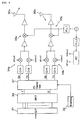
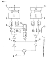
- FIGURE 2 is a block diagram showing the internal configuration of a transmitting device 2b of the transmitting and receiving station 2.
- the transmitting device 2b comprises a serial/parallel (S/P) converting circuit 31, an fd setting circuit 32, an inverse Fourier transform circuit 33, QPSK modulation circuits 34a and 34b, up-converters 35a and 35b and the like.
- S/P serial/parallel
- the inverse Fourier transform circuit 33 realizes various functions as follows.
- the inverse Fourier transform circuit 33 performs inverse Fourier transform on the transmitted data supplied in parallel from the S/P converting circuit 31, converts the inverse Fourier transformed data to return it to serial, and time-compresses a serial symbol string so as to move a posterior symbol to the beginning of the string, thereby setting a guard time.
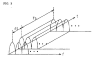
- FIGURE 3 is a graph showing the symbol transmission by OFDM on a frequency axis f and a time axis t.
- An effective symbol length is represented by TS, and a guard time is given by ⁇ t.
- a time compression ratio is represented by (TS + ⁇ t)/TS.
- the transmitting and receiving station 2 and the vehicle-mounted mobile station 4 can avoid intersymbol interference so as to accurately restore the received signal without being adversely affected by the propagation delay due to the presence of a plurality of propagation paths for the radio wave (multipath).
- the QPSK modulation circuits 34a and 34b perform QPSK transform by D/A converting a signal corresponding to the phase 0° and a signal corresponding to the phase 180°, and a signal corresponding to the phase 90° and a signal corresponding to the phase 270° which are output from the inverse Fourier transform circuit 33, subjecting these signals respectively to a sin wave and a cos wave, and adding them.
- QPSK modulation is performed in this embodiment, other modulation methods, for example, QAM, BPSK, 8PSK and the like may be used. In the following description, however, it is assumed that QPSK modulation is performed unless specifically noted.
- the up-converters 35a and 35b are circuits for frequency conversion into a wireless frequency.
- the output signals from the up-converters 35a and 35b pass through a circulator and a coaxial cable to be emitted from road antennas 36a and 36b as radio waves.
- the f d setting circuit 32 is a circuit for setting an offset frequency f d .
- This setting of the offset frequency there are methods of: (1) detecting running speed of a vehicle moving on the road in real time, thereby setting the offset frequency; and (2) previously giving the offset frequency as a constant.
- a method for obtaining average running speed of the vehicles based on the speed information transmitted from each vehicle within the cell there are (1-1) a method for obtaining average running speed of the vehicles based on the speed information transmitted from each vehicle within the cell; (1-2) a method for obtaining average running speed by detecting the speed of each vehicle with an ultrasonic speed sensor or a television camera being arranged on the road; and (1-3) a method for obtaining the average running speed of the vehicles by detecting the speed of each vehicle based on Doppler shift ⁇ f detected on automatic frequency control (AFC) in the receiving device 2a.
- AFC automatic frequency control
- a signal corresponding to the thus set offset frequency + fd is supplied to a voltage control oscillation (VCO) circuit. Then, a signal having an angular frequency of ⁇ + 2 ⁇ fd is generated by a PLL oscillator. After being provided with a phase difference of 90° by a phase-shift circuit, the signal having an angular frequency of ⁇ + 2 ⁇ fd is supplied to the QPSK modulation circuit 34a.
- VCO voltage control oscillation
- a signal corresponding to the offset frequency - fd is supplied to a VCO circuit. Then, a signal having an angular frequency of ⁇ - 2 ⁇ fd is generated by the PLL oscillator. After being provided with a phase difference of 90° by the phase-shift circuit, the signal having an angular frequency of ⁇ - 2 ⁇ fd is supplied to the QPSK modulation circuit 34b.
- a frequency signal having an offset of + fd is obtained from the QPSK modulation circuit 34a while a frequency signal having an offset of - fd is obtained from the QPSK modulation circuit 34b.
- FIGURE 4 is a block diagram showing an exemplary modification of the internal configuration of the transmitting device 2b shown in FIG. 2 .
- the circuit configuration shown in FIG. 4 differs from that shown in FIG. 2 in that a signal I having an in-phase component and a signal Q having an orthogonal component to be input into the QPSK modulation circuit 34 are subjected to frequency correction so as to be provided with offsets while signals having angular frequencies of ⁇ ⁇ 2 ⁇ f d are supplied to a local oscillation circuit of the QPSK modulation circuit 34 so as to be provided with offsets in the circuit configuration of FIG. 2 .
- a circuit for correcting the offset frequency is an f d correction circuit 37.
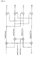
- FIGURE 5 is a circuit diagram showing the internal configuration of the fd correction circuit 37.
- the fd correction circuit 37 produces signals of cos(2 ⁇ fdt) and sin(2 ⁇ fdt) based on the information of the offset frequency fd obtained from the fd setting circuit 32.
- the signal I having an in-phase component and the signal Q having an orthogonal component output from the inverse Fourier transform circuit 33 are respectively multiplied by cos(2 ⁇ fdt) and sin(2 ⁇ fdt) to obtain four signals: I cos 2 ⁇ ⁇ ⁇ f d ⁇ t , I sin 2 ⁇ ⁇ ⁇ f d ⁇ t , Q cos 2 ⁇ ⁇ ⁇ f d ⁇ t , and Q sin 2 ⁇ ⁇ ⁇ f d ⁇ t
- Ia I cos 2 ⁇ ⁇ ⁇ f d ⁇ t - Q sin 2 ⁇ ⁇ ⁇ f d ⁇ t
- Qa Q cos 2 ⁇ ⁇ ⁇ f d ⁇ t + I sin 2 ⁇ ⁇ ⁇ f d ⁇ t
- Ib I cos 2 ⁇ ⁇ ⁇ f d ⁇ t + Q sin 2 ⁇ ⁇ ⁇ f d ⁇ t
- Qb Q cos 2 ⁇ ⁇ ⁇ f d ⁇ - I sin 2 ⁇ ⁇ ⁇ f d ⁇ t
- Ia and Qa are supplied to the QPSK modulation circuit 34a while Ib and Qb are supplied to the QPSK modulation circuit 34b.
- a frequency signal having an offset of + f d is obtained from the QPSK modulation circuit 34a while a frequency signal having an offset of - f d is obtained from the QPSK modulation circuit 34b.
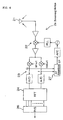
- FIGURE 6 is a block diagram showing the internal configuration of the receiving device 2a of the receiving and transmitting station 2.
- the receiving device 2a comprises a receiving antenna 21, a down-converter 22, a QPSK demodulation circuit 23, a Fourier transform circuit 24, a P/S (parallel/serial) converting circuit 26, a ⁇ f detecting section 27, and the like.
- the down-converter 22 of the receiving device 2a is a circuit which converts a wireless frequency into an intermediate frequency.
- the QPSK demodulation circuit 23 performs QPSK demodulation, wherein one of two divided signals is subjected to a sin wave while the other divided signal is subjected to a cos wave whose phase differs by 90° from that of the sin wave so as to A/D convert these divided signals.
- the frequency difference ⁇ f detecting section 27 detects a deviation ⁇ f of the received frequency based on the in-phase component I (signal after being subjected to a cos wave) and the orthogonal component Q (signal after being subjected to a sin wave) of the QPSK demodulation circuit 23.
- the deviation ⁇ f of the received frequency can be obtained based on a difference between a deflection angle (I/Q) t of a current I/Q and a deflection angle (I/Q) t-1 sampled immediately before I/Q which are obtained by calculating the deflection angle of a complex number I/Q at sampling time intervals.
- ⁇ f I / Q t - I / Q t - 1
- the ⁇ f detecting section 27 feeds back the deviation ⁇ f of the received frequency to the down-converter 22 and the QPSK demodulation circuit 23, thereby accomplishing the function of correcting the deviation ⁇ f of the received frequency.
- the Fourier transform circuit 24 performs processing that is opposite to that of the inverse Fourier transform circuit 33 on the transmission side.
- the Fourier transform circuit 24 performs Fourier transform on the QPSK demodulated signal with the effective symbol length TS as a window length, thereby obtaining a demodulated signal.
- the P/S converting circuit 26 converts a Fourier transformed parallel signal into a serial signal.
- This data converted into a serial signal is transmitted to the central base station 1.
- FIGURE 7 is a conceptual view showing the configuration of a vehicle-mounted mobile station 4.
- the vehicle-mounted mobile station 4 consists of a transmitting and receiving antenna 61, a receiving section, a transmitting section and a frequency control section.
- the transmitting section comprises a S/P converting circuit 47, an inverse Fourier transform circuit 49, a QPSK modulation circuit 50, and an up-converter 51 and the like.
- the receiving section comprises a down-converter 66 for converting a wireless frequency into an intermediate frequency, a QPSK demodulation circuit 63, a Fourier transform circuit 64, a P/S converting circuit 65 and the like. Since the configuration of the receiving part is also well-known and is similar to that of the receiving device 2a described with reference to FIG. 6 , the description thereof is herein omitted.
- the frequency control section has the function of detecting a deviation ⁇ f of the received frequency of the receiving section and the function of performing frequency control of the receiving section based on the deviation ⁇ f.
- deflection angles I/Q of a complex number I/Q are calculated at sample time intervals based on the in-phase component I (signal after being subjected to a cos wave) and the orthogonal component Q (signal after being subjected to a sin wave) of the QPSK demodulation circuit 63.
- the deviation ⁇ f of the received frequency is then detected based on the difference between the deflection angle (I/Q) t of the current I/Q and a deflection angle (I/Q) t-1 sampled immediately before.
- ⁇ f I / Q t - I / Q t - 1
- the frequency control section feeds back the detected deviation ⁇ f of the received frequency to an oscillator of the down-converter 66, thereby accomplishing the function of correcting the deviation ⁇ f of the received frequency.
- f f org - ⁇ f
- f org is a frequency at which oscillation occurs when ⁇ f is 0.
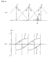
- FIGURE 8 is a graph showing the thus obtained deviations ⁇ f of frequencies.
- FIGURE 8(a) shows the arrangement of road antennas a1, a2; b1, b2; c1 and c2 of a road transmission equipment of the present invention and a vehicle running thereunder.
- a transmitting and receiving antenna hereinafter, simply referred to as a "receiving antenna” 61 and a vehicle-mounted mobile station 4 are mounted.
- FIGURE 8(b) is a graph showing the transitions of the deviations ⁇ f of frequencies.
- the transition of a deviation of the frequency that the receiving antenna 61 receives from the road antenna a2 is indicated by the line a2
- the transition of a deviation of the frequency that the receiving antenna 61 receives from the road antenna b1 is indicated by the line b1
- the transition of a deviation of the frequency that the receiving antenna 61 receives from the road antenna b2 is indicated by the line b2
- the transition of a deviation of the frequency that the receiving antenna 61 receives from the road antenna c1 is indicated by the line c1.
- the deviation ⁇ f of the frequency is reduced to be almost half of that in FIG. 9 owing to the frequency offset fd of the transmitting device 2b on the road.
- the frequency offset fd the Doppler shift to which the vehicle is subjected is halved immediately under the road antennas a1 and a2.
- the skipping of the frequency does not theoretically occur in the case of FIG. 9 , whereas the skipping occurs in the case of FIG. 8 .
- the reason for the occurrence of skipping in the case of FIG. 8 can be explained as follows. Since two antennas, each having a different direction, are provided in a single transmitting and receiving station in the present invention, the received radio waves from these antennas are exchanged when the vehicle passes immediately under the transmitting and receiving station B, thereby causing the skipping of the frequency corresponding to double the amount of the deviation of the offset frequency.
Abstract
Description
- The present invention relates to a road transmission equipment used in a communication system between a road and a vehicle, allowing mobile communication between a road and a mobile station by locating a plurality of road antennas along the road to form a cell on the road.
- There is an increasing demand for communications between road controllers and vehicles. On a superhighway, in particular, to enable a vehicle to operate on the road without any burden on the driver and any accident both for the controller and the driver, frequent interchange of information is necessary between the road and the vehicle. One type of such a developed system is a self-operating system that allows a vehicle to run with close communication between the road and the vehicle, which are equipped with various sensors and a camera (see, for example, Japanese Unexamined Patent Publication No.
241495 of 1996 - For the construction of a driving support system (hereinafter, referred to as "communication system between a road and a vehicle") which makes use of the communication with the vehicle for future extension into a self-operating system, it is necessary to provide a communication area (cell) on the road.
- To provide such a cell, we may consider laying a leakage coaxial cable along the road. However, the drawback of this method is that large-scale construction is needed for laying such a cable. In addition, since it is required to locate the leakage coaxial cable at a relatively low position on the ground, the distance for which a radio wave propagates in a direction across a traffic lane is disadvantageously short.
- On the other hand, if the communication is performed with a plurality of road antennas being arranged on the road at predetermined intervals, a single road antenna can cover a relatively large cell. In this case, each of the road antennas is connected to a central base station of the road controller via an optical fiber and the like.
- In the case where the road antennas are provided, when a large-size vehicle comes proximate to a small-size vehicle, it obstructs the view of the driver of the small-size vehicle, preventing him from seeing the road antenna from inside the small-size vehicle. In particular, it is likely that a microwave or a millimeter wave of a high frequency having a small angle of diffraction is blocked. Accordingly, the communication between the vehicle and the road is interrupted, thereby preventing continued communications.
- Therefore, in order to enable continuous communications between the road and the vehicle, multi-station communication has been proposed. According to this multi-station communication, a plurality of road antennas having an inherent directivity are provided along the road, and radio waves of the same frequency and the same content are emitted from the respective road antennas toward the same cell.
- A multi-station communication system is advantageous because such a system has a plurality of propagation paths for radio waves to be emitted and therefore the radio wave avoids being blocked so as to continuously perform smooth communication between a mobile station and a road communication station even when a vehicle runs proximate to a large-size vehicle such as a truck.
- In the multi-station communication system, however, the Doppler effect occurs when a vehicle moves. The antennas receiving radio waves from the front and behind receive radio waves of respectively different frequencies based on Doppler shift.
-
FIGURE 9(a) shows an arrangement of conventional road antennas a, b, and c in a multi-station communication system and a vehicle running under these antennas. A receivingantenna 61 and a receivingdevice 4 are mounted on the vehicle. -
FIGURE 9(b) is a graph showing the transitions of deviations of the frequencies received by thereceiving antenna 61. The transition of a deviation of the frequency received by thereceiving antenna 61 from the road antenna a is indicated by a line a, the transition of a deviation of the frequency received by the receivingantenna 61 from the road antenna b is indicated by a line b, and the transition of a deviation of the frequency received by thereceiving antenna 61 from the road antenna c is indicated by a line c. - An exemplar value of the deviation of the frequency received from the road antenna a will be given. Doppler shift Δ f is expressed by: Δ f = f0 v/c (c is a velocity of light), where a transmitted frequency of the road antenna is
f 0, and v is a velocity of a vehicle. When the vehicle runs on the road, the Doppler shift Δ f is given by:
where the height of the road antenna from the ground is H, and a distance between the vehicle and the road antenna is L. Assuming f0 = 5.8 GHz, v = 100 km/h, and H=10 (m), the Doppler shift Δ fis expressed by:
When the distance between the road antennas is set to 50 (m), the value of L ranges from 0 (m) to 50 (m). Accordingly, the Doppler shift Δ f ranges from 0 to 527(Hz). At the middle point between the antennas, i.e. L = 25(m), the Doppler shift Δ f is 499(Hz). - With the arrangement of the road antennas as shown in
FIG. 9(a) , there occurs skipping of received frequencies as shown inFIG. 9(b) each time a vehicle passes near the middle point between the antennas. This skipping is caused because the automatic frequency control (AFC) of thereceiving device 4 is drawn toward the frequency having greater receiving power. This skipping makes it difficult to follow the frequency control in a receiving section, resulting in the interruption of communication during the occurrence of skipping. - Accordingly, it is desired to reduce the Doppler effect on the side of the road-transmitting device in the communication system between a road and a vehicle performing communication between a plurality of road communication stations arranged in a cell and a vehicle-mounted mobile station within the cell.
-
DE 3508 069 describes a communication system with readjusted transmission frequencies. -
- (1) A road transmission equipment as set forth in
Claim 1 with the view of achieving the abovementioned object, comprises:- a first transmitting antenna having a directivity in a running direction of a vehicle,
- a second transmitting antenna having a directivity in a direction opposite to the running direction of the vehicle, a first transmitting section and a second transmitting section respectively connected to the first transmitting antenna and the second transmitting antenna to output signals of the same frequency, and
- a frequency correction section, wherein;
- the frequency correction section performs correction so as to provide the first transmitting section with a positive frequency offset for increasing a frequency of a signal supplied to the first transmitting antenna, and so as to provide the second transmitting section with a negative frequency offset for lowering a frequency of a signal supplied to the second transmitting antenna.
Therefore, the variation in the received frequency based on the Doppler shift is reduced for the vehicle-mounted receiving device to lessen the requirements for frequency control of automatic frequency control (AFC). Thus, the degradation of the quality of data after demodulation is reduced. - (2) It is preferred that the amounts of the positive frequency offset and the negative frequency offset provided by the frequency correction section are equal to each other (Claim 2).
The reason being that since the running speed of the vehicle is normally almost consistent within the cell, the amount of Doppler shift of the radio wave directed in the running direction of the vehicle, to which the vehicle-mounted receiving device is subjected, is also considered to be the same as that of the radio wave directed in the opposite direction to the running direction, to which the vehicle-mounted receiving device is subjected. - (3) The road transmission equipment according to the present invention may further comprise a speed detection means for detecting the speed of the vehicle running in the cell, wherein
the frequency correction section may set the amount of the frequency offset based on the detected speed of the vehicle (Claim 3).
Since the amount of Doppler shift of the vehicle-mounted receiving device can be obtained if the running speed of the vehicle can be detected, the amount of a frequency offset can be set based on the amount of the Doppler shift. Accordingly, in the case where the speed of the vehicle changes with time, accurate frequency correction can be performed in real time.
When a plurality of vehicles are present in the cell and the speed of each vehicle can be detected, the amount of frequency offset is set based on the average value of the speeds of a plurality of vehicles. - (4) The amount of the frequency offset provided by the frequency correction section may be set to a fixed value on the assumption that the vehicle is subjected to constant Doppler shift (Claim 4).
Normally, it is considered that the running speed of a vehicle is almost always consistent within the same cell on the same road and does not greatly change with time (although the running speed changes considerably in the case of traffic restriction or traffic congestion, the frequency and the duration of traffic restriction or traffic congestion cannot be predicted).
Therefore, even with the fixed amount of frequency offset, the object of the present invention of reducing the variation in the received frequency based on the Doppler shift can be achieved.
Moreover, since the speed detection means is no longer needed, the configuration of the road transmission equipment is advantageously simplified. - (5) The first transmitting section and the second transmitting section may transmit an orthogonal frequency division multiplex (OFDM) modulated radio wave (Claim 5).
- In a case where an OFDM modulation method is used for dividing transmitted information into subcarriers and transmitting the obtained subcarriers, the sensitivity of a bit error rate with respect to a frequency disarrangement is high because a distance between the frequencies of adjacent subcarriers is small. Accordingly, in a conventional communication system between a road and a vehicle as illustrated in
FIG. 9 , a Doppler frequency change increases, thereby degrading the transmission characteristics. - Since the correction for providing a frequency with an offset is performed so as to reduce a Doppler frequency change in the present invention, the present invention is extremely effective for a communication system between a road and a vehicle using an OFDM modulation method.
-
-
FIGURE 1 is a conceptual view showing the configuration of a communication system between a road and a vehicle. -
FIGURE 2 is a block diagram showing the internal configuration of a transmittingdevice 2b of a transmitting and receivingstation 2. -
FIGURE 3 is a graph illustrating symbol transmission by OFDM on a frequency axis f and a time axis t. -
FIGURE 4 is a block diagram showing an exemplary modification of the internal configuration of the transmittingdevice 2b shown inFIG. 2 . -
FIGURE 5 is a circuit diagram showing an fd correction circuit 37 of the transmittingdevice 2b shown inFIG. 4 . -
FIGURE 6 is a block diagram showing the internal configuration of a receivingdevice 2a of the transmitting and receivingstation 2. -
FIGURE 7 is a conceptual view showing the configuration of a vehicle-mountedmobile station 4. -
FIGURE 8(a) is a layout drawing showing the arrangement of road antennas a1, a2; b1, b2; c1 and c2 of the road transmission equipment according to the present invention and a vehicle running thereunder; andFIG. 8(b) is a graph showing the transition of a deviation Δ f of a frequency received by the vehicle-mounted mobile station. -
FIGURE 9(a) is a layout drawing showing the arrangement of three road antennas a, b, and c of a conventional multi-station communication system and a vehicle running thereunder; andFIG. 9(b) is a graph showing the transition of a deviation of a received frequency. - Hereinafter, a preferred embodiment of the present invention will be described in detail with reference to the attached drawings.
-
FIGURE 1 is a conceptual view showing the configuration of a communication system between a road and a vehicle. This communication system between a road and a vehicle transmits and receives road transportation information between a road communication station and a mobile station mounted on a vehicle. - A cell is formed along the road. In the cell or in the vicinity thereof, a plurality of transmitting and receiving
stations 2 are arranged at intervals. Each of the transmitting and receivingstations 2 has anantenna 36a having a forward directivity and anantenna 36b having a rearward directivity along a running direction of the vehicle. - A radio wave having a frequency offset toward the positive side is emitted into the cell from the
antennas 36a having a forward directivity, while a radio wave having a frequency offset toward the negative side is emitted into the cell from theantennas 36b having a rearward directivity. - The radio waves emitted from the antennas have the same frequency with exclusion of the offsets.
- The transmitting and receiving
station 2 acquires transmitted data via awire transmission line 9 such as an optical fiber or a coaxial cable (although a wireless transmission line may be used instead of the wire transmission line, it is assumed hereinafter to use the "wire transmission line 9") from acentral base station 1. The transmitted data is then subjected to OFDM modulation using a plurality of carrier waves (subcarriers) orthogonally crossing each other, and is transmitted as a wireless radio wave into the cell. The transmitting and receivingstation 2 receives the OFDM modulated wireless radio wave from the vehicle-mountedmobile station 4 in the cell, and then perform OFDM demodulation on this wireless radio wave so as to transmit the received data via thewire transmission line 9 from thecentral base station 1. - The combination of the function of the transmitting and receiving
station 2 and the function of thecentral base station 1 will be referred to as the "road communication station". - The reason for use of the OFDM modulation method is as follows.
- In the case of multi-station communication, since a plurality of radio waves are emitted with similar transmission power into the same cell, phasing is caused by multipath. As a result, intercarrier interference or intersymbol interference frequently occurs. Consequently, it is essential to remove the effects of such interference in the system construction.
- Generally, a mobile object communication system using a single carrier is likely to be subjected to the effect of intersymbol interference by the multipath delayed wave.
- Accordingly, it is proposed to use the OFDM modulation method that is capable of transmitting a plurality of subcarriers obtained by dividing a carrier. The OFDM modulation method is advantageous in that the effects of a delayed wave can be eliminated by setting a guard time.
-
FIGURE 2 is a block diagram showing the internal configuration of atransmitting device 2b of the transmitting and receivingstation 2. - The transmitting
device 2b comprises a serial/parallel (S/P) convertingcircuit 31, anfd setting circuit 32, an inverseFourier transform circuit 33,QPSK modulation circuits converters - The inverse
Fourier transform circuit 33 realizes various functions as follows. The inverseFourier transform circuit 33 performs inverse Fourier transform on the transmitted data supplied in parallel from the S/P converting circuit 31, converts the inverse Fourier transformed data to return it to serial, and time-compresses a serial symbol string so as to move a posterior symbol to the beginning of the string, thereby setting a guard time. -
FIGURE 3 is a graph showing the symbol transmission by OFDM on a frequency axis f and a time axis t. An effective symbol length is represented by TS, and a guard time is given by Δt. A time compression ratio is represented by (TS + Δt)/TS. In the case of QPSK, TS is expressed by:
where the number of subcarriers is n, and the transmission rate is m (Mbps). - It is required to set the guard time Δt of the OFDM modulation to be longer than the time delayed by the multipath. In this way, the transmitting and receiving
station 2 and the vehicle-mountedmobile station 4 can avoid intersymbol interference so as to accurately restore the received signal without being adversely affected by the propagation delay due to the presence of a plurality of propagation paths for the radio wave (multipath). - With reference to
FIG. 2 , theQPSK modulation circuits phase 0° and a signal corresponding to the phase 180°, and a signal corresponding to the phase 90° and a signal corresponding to the phase 270° which are output from the inverseFourier transform circuit 33, subjecting these signals respectively to a sin wave and a cos wave, and adding them. - Needless to say, although QPSK modulation is performed in this embodiment, other modulation methods, for example, QAM, BPSK, 8PSK and the like may be used. In the following description, however, it is assumed that QPSK modulation is performed unless specifically noted.
- The up-
converters converters road antennas - Herein, a method for providing a frequency with an offset in the QPSK modulation circuit 34 will be described.
- The fd setting circuit 32 is a circuit for setting an offset frequency fd. For this setting of the offset frequency, there are methods of: (1) detecting running speed of a vehicle moving on the road in real time, thereby setting the offset frequency; and (2) previously giving the offset frequency as a constant.
- For detecting the running speed of a vehicle according to the method (1), for example, there are (1-1) a method for obtaining average running speed of the vehicles based on the speed information transmitted from each vehicle within the cell; (1-2) a method for obtaining average running speed by detecting the speed of each vehicle with an ultrasonic speed sensor or a television camera being arranged on the road; and (1-3) a method for obtaining the average running speed of the vehicles by detecting the speed of each vehicle based on Doppler shift Δ f detected on automatic frequency control (AFC) in the receiving
device 2a. - In the method (2) of previously giving an offset frequency as a constant, it is assumed that the vehicle always runs at the speed which has been previously obtained in a statistical or experimental fashion within the cell. On the road
where traffic is constant, the configuration can be simplified with the running speed of a vehicle being fixed as a constant rather than with the running speed detected in real time because it is not necessary to provide a running speed detection means. - The amount of the offset frequency fd is set to be a half of the maximum Doppler shift Fd (fd = Fd/2) which a vehicle experiences in a case where the vehicle runs at said speed.
- A signal corresponding to the thus set offset frequency + fd is supplied to a voltage control oscillation (VCO) circuit. Then, a signal having an angular frequency of ω + 2π fd is generated by a PLL oscillator. After being provided with a phase difference of 90° by a phase-shift circuit, the signal having an angular frequency of ω + 2π fd is supplied to the
QPSK modulation circuit 34a. - On the other hand, a signal corresponding to the offset frequency - fd is supplied to a VCO circuit. Then, a signal having an angular frequency of ω - 2π fd is generated by the PLL oscillator. After being provided with a phase difference of 90° by the phase-shift circuit, the signal having an angular frequency of ω - 2π fd is supplied to the
QPSK modulation circuit 34b. - As a result, a frequency signal having an offset of + fd is obtained from the
QPSK modulation circuit 34a while a frequency signal having an offset of - fd is obtained from theQPSK modulation circuit 34b. -
FIGURE 4 is a block diagram showing an exemplary modification of the internal configuration of the transmittingdevice 2b shown inFIG. 2 . - In comparison, the circuit configuration shown in
FIG. 4 differs from that shown inFIG. 2 in that a signal I having an in-phase component and a signal Q having an orthogonal component to be input into the QPSK modulation circuit 34 are subjected to frequency correction so as to be provided with offsets while signals having angular frequencies of ω ± 2 π fd are supplied to a local oscillation circuit of the QPSK modulation circuit 34 so as to be provided with offsets in the circuit configuration ofFIG. 2 . - A circuit for correcting the offset frequency is an fd correction circuit 37.
-
FIGURE 5 is a circuit diagram showing the internal configuration of thefd correction circuit 37. Thefd correction circuit 37 produces signals of cos(2π fdt) and sin(2π fdt) based on the information of the offset frequency fd obtained from thefd setting circuit 32. Then, the signal I having an in-phase component and the signal Q having an orthogonal component output from the inverseFourier transform circuit 33 are respectively multiplied by cos(2π fdt) and sin(2π fdt) to obtain four signals:


- Furthermore, these four signals are added and subtracted so as to obtain Ia, Ib, Qa and Qb:


- Then, Ia and Qa are supplied to the
QPSK modulation circuit 34a while Ib and Qb are supplied to theQPSK modulation circuit 34b. - As a result, a frequency signal having an offset of + fd is obtained from the
QPSK modulation circuit 34a while a frequency signal having an offset of - fd is obtained from theQPSK modulation circuit 34b. -
FIGURE 6 is a block diagram showing the internal configuration of the receivingdevice 2a of the receiving and transmittingstation 2. - The receiving
device 2a comprises a receivingantenna 21, a down-converter 22, aQPSK demodulation circuit 23, aFourier transform circuit 24, a P/S (parallel/serial) convertingcircuit 26, a Δf detecting section 27, and the like. - The down-
converter 22 of the receivingdevice 2a is a circuit which converts a wireless frequency into an intermediate frequency. - In contrast with the QPSK modulation circuit 34, the
QPSK demodulation circuit 23 performs QPSK demodulation, wherein one of two divided signals is subjected to a sin wave while the other divided signal is subjected to a cos wave whose phase differs by 90° from that of the sin wave so as to A/D convert these divided signals. - The frequency difference Δ
f detecting section 27 detects a deviation Δ f of the received frequency based on the in-phase component I (signal after being subjected to a cos wave) and the orthogonal component Q (signal after being subjected to a sin wave) of theQPSK demodulation circuit 23. The deviation Δ f of the received frequency can be obtained based on a difference between a deflection angle (I/Q)t of a current I/Q and a deflection angle (I/Q)t-1 sampled immediately before I/Q which are obtained by calculating the deflection angle of a complex number I/Q at sampling time intervals.
- The Δ
f detecting section 27 feeds back the deviation Δ f of the received frequency to the down-converter 22 and theQPSK demodulation circuit 23, thereby accomplishing the function of correcting the deviation Δ f of the received frequency. - The
Fourier transform circuit 24 performs processing that is opposite to that of the inverseFourier transform circuit 33 on the transmission side. TheFourier transform circuit 24 performs Fourier transform on the QPSK demodulated signal with the effective symbol length TS as a window length, thereby obtaining a demodulated signal. - The P/
S converting circuit 26 converts a Fourier transformed parallel signal into a serial signal. - This data converted into a serial signal is transmitted to the
central base station 1. - Next, the configuration of a vehicle-mounted mobile station to be mounted in the vehicle will be described.
-
FIGURE 7 is a conceptual view showing the configuration of a vehicle-mountedmobile station 4. The vehicle-mountedmobile station 4 consists of a transmitting and receivingantenna 61, a receiving section, a transmitting section and a frequency control section. - The transmitting section comprises a S/
P converting circuit 47, an inverseFourier transform circuit 49, aQPSK modulation circuit 50, and an up-converter 51 and the like. - The description for actions of the transmitting section is herein omitted because the configuration of the transmitting section is well-known and is identical with the main part of the configuration of the transmitting
device 2b on the road shown inFIG. 2 . - The receiving section comprises a down-
converter 66 for converting a wireless frequency into an intermediate frequency, aQPSK demodulation circuit 63, aFourier transform circuit 64, a P/S converting circuit 65 and the like. Since the configuration of the receiving part is also well-known and is similar to that of the receivingdevice 2a described with reference toFIG. 6 , the description thereof is herein omitted. - The frequency control section has the function of detecting a deviation Δ f of the received frequency of the receiving section and the function of performing frequency control of the receiving section based on the deviation Δ f.
- The function of detecting the deviation Δ f of the received frequency can be described in the same manner as that for the function of the Δ
f detecting section 27 described with reference toFIG. 6 . Specifically, deflection angles I/Q of a complex number I/Q are calculated at sample time intervals based on the in-phase component I (signal after being subjected to a cos wave) and the orthogonal component Q (signal after being subjected to a sin wave) of theQPSK demodulation circuit 63. The deviation Δ f of the received frequency is then detected based on the difference between the deflection angle (I/Q)t of the current I/Q and a deflection angle (I/Q)t-1 sampled immediately before.
- The frequency control section feeds back the detected deviation Δ f of the received frequency to an oscillator of the down-
converter 66, thereby accomplishing the function of correcting the deviation Δ f of the received frequency.
where forg is a frequency at which oscillation occurs when Δ f is 0. -
FIGURE 8 is a graph showing the thus obtained deviations Δ f of frequencies. -
FIGURE 8(a) shows the arrangement of road antennas a1, a2; b1, b2; c1 and c2 of a road transmission equipment of the present invention and a vehicle running thereunder. Onvehicle 4, as described above, a transmitting and receiving antenna (hereinafter, simply referred to as a "receiving antenna") 61 and a vehicle-mountedmobile station 4 are mounted. -
FIGURE 8(b) is a graph showing the transitions of the deviations Δ f of frequencies. The transition of a deviation of the frequency that the receivingantenna 61 receives from the road antenna a2 is indicated by the line a2, the transition of a deviation of the frequency that the receivingantenna 61 receives from the road antenna b1 is indicated by the line b1, the transition of a deviation of the frequency that the receivingantenna 61 receives from the road antenna b2 is indicated by the line b2, and the transition of a deviation of the frequency that the receivingantenna 61 receives from the road antenna c1 is indicated by the line c1. - As can be seen in the graph of
FIG. 8(b) , the deviation Δ f of the frequency is reduced to be almost half of that inFIG. 9 owing to the frequency offset fd of the transmittingdevice 2b on the road. For instance, taking b1 as an example, if there is no frequency offset fd, the vehicle is subjected to the Doppler shift of Fd at the maximum. However, since the frequency offset fd has been previously provided, the Doppler shift to which the vehicle is subjected is halved immediately under the road antennas a1 and a2. - Moreover, it is understood that the skipping of a frequency occurring in the vicinity A of the middle position between road antennas with movement of the vehicle is almost halved. Accordingly, in the case where automatic frequency control (AFC) is performed, the followability to frequency control is sufficient. As a result, the communication is not interrupted.
- When the vehicle passes immediately under the transmitting and receiving station B, the skipping of the frequency does not theoretically occur in the case of
FIG. 9 , whereas the skipping occurs in the case ofFIG. 8 . The reason for the occurrence of skipping in the case ofFIG. 8 can be explained as follows. Since two antennas, each having a different direction, are provided in a single transmitting and receiving station in the present invention, the received radio waves from these antennas are exchanged when the vehicle passes immediately under the transmitting and receiving station B, thereby causing the skipping of the frequency corresponding to double the amount of the deviation of the offset frequency. - Although the embodiment of the present invention has been described above, the present invention is not limited thereto. Various changes and modification in the design can be made without departing from the scope of the present invention.
Claims (5)
- A road transmission equipment used for a communication system between a road and a vehicle, which communicates between a road communication station arranged in a cell and a vehicle-mounted mobile station within the cell, comprising:- a first transmitting antenna (36a) having a directivity in a running direction of a vehicle (4),- a second transmitting antenna (36b) having a directivity in the opposite direction to the running direction of the vehicle (4),- a first transmitting section and a second transmitting section respectively connected to the first transmitting antenna and the second transmitting antenna to output signals of the same frequency, and- a frequency correction section, wherein; the frequency correction section provides the first transmitting section with a positive frequency offset for increasing the frequency of a signal supplied to the first transmitting antenna, and provides the second transmitting section with a negative frequency offset for lowering the frequency of a signal supplied to the second transmitting antenna.
- A road transmission equipment as set forth in Claim 1, wherein
the amounts of the positive frequency offset and the negative frequency offset provided by the frequency correction section are equal to each other. - A road transmission equipment as set forth in Claim 1, further comprising a speed detection means for detecting the speed of the vehicle running in the cell, wherein
the frequency correction section sets the amount of the frequency offset based on the detected speed of the vehicle. - A road transmission equipment as set forth in Claim 1, wherein
the amount of the frequency offset provided by the frequency correction section is set to a fixed value on the assumption that the vehicle is subjected to constant Doppler shift. - A road transmission equipment according to any one of the preceding claims, wherein
each of the first transmitting section and the second transmitting section transmits an orthogonal frequency division multiplex (OFDM) modulated radio wave.
Applications Claiming Priority (3)
| Application Number | Priority Date | Filing Date | Title |
|---|---|---|---|
| JP19348599A JP3367476B2 (en) | 1999-07-07 | 1999-07-07 | Roadside transmission device |
| JP19348599 | 1999-07-07 | ||
| PCT/JP2000/004122 WO2001005065A1 (en) | 1999-07-07 | 2000-06-22 | Roadside transmitter |
Publications (3)
| Publication Number | Publication Date |
|---|---|
| EP1119115A1 EP1119115A1 (en) | 2001-07-25 |
| EP1119115A4 EP1119115A4 (en) | 2004-10-20 |
| EP1119115B1 true EP1119115B1 (en) | 2009-12-30 |
Family
ID=16308827
Family Applications (1)
| Application Number | Title | Priority Date | Filing Date |
|---|---|---|---|
| EP00939137A Expired - Lifetime EP1119115B1 (en) | 1999-07-07 | 2000-06-22 | Roadside transmitter |
Country Status (8)
| Country | Link |
|---|---|
| US (1) | US6397067B1 (en) |
| EP (1) | EP1119115B1 (en) |
| JP (1) | JP3367476B2 (en) |
| KR (1) | KR20010074982A (en) |
| AT (1) | ATE453971T1 (en) |
| DE (1) | DE60043607D1 (en) |
| IL (2) | IL141700A0 (en) |
| WO (1) | WO2001005065A1 (en) |
Families Citing this family (25)
| Publication number | Priority date | Publication date | Assignee | Title |
|---|---|---|---|---|
| US7120431B1 (en) * | 1999-02-12 | 2006-10-10 | Lucent Technologies Inc. | System and method for adjusting antenna radiation in a wireless network |
| US7952511B1 (en) | 1999-04-07 | 2011-05-31 | Geer James L | Method and apparatus for the detection of objects using electromagnetic wave attenuation patterns |
| JP3782330B2 (en) * | 2001-09-14 | 2006-06-07 | 富士通株式会社 | OFDM receiving method and OFDM receiving apparatus |
| CA2516430C (en) * | 2003-02-28 | 2011-11-22 | Yozo Shoji | Wireless communication system |
| TWI247490B (en) * | 2003-03-25 | 2006-01-11 | Buffalo Inc | Access point |
| US7415243B2 (en) | 2003-03-27 | 2008-08-19 | Honda Giken Kogyo Kabushiki Kaisha | System, method and computer program product for receiving data from a satellite radio network |
| US7818380B2 (en) | 2003-12-15 | 2010-10-19 | Honda Motor Co., Ltd. | Method and system for broadcasting safety messages to a vehicle |
| US8041779B2 (en) | 2003-12-15 | 2011-10-18 | Honda Motor Co., Ltd. | Method and system for facilitating the exchange of information between a vehicle and a remote location |
| WO2005099379A2 (en) | 2004-04-06 | 2005-10-27 | Honda Motor Co., Ltd. | Method and system for controlling the exchange of vehicle related messages |
| US7518530B2 (en) * | 2004-07-19 | 2009-04-14 | Honda Motor Co., Ltd. | Method and system for broadcasting audio and visual display messages to a vehicle |
| US7643788B2 (en) | 2004-09-22 | 2010-01-05 | Honda Motor Co., Ltd. | Method and system for broadcasting data messages to a vehicle |
| US8370054B2 (en) * | 2005-03-24 | 2013-02-05 | Google Inc. | User location driven identification of service vehicles |
| US7562049B2 (en) * | 2005-03-29 | 2009-07-14 | Honda Motor Co., Ltd. | Payment system and method for data broadcasted from a remote location to vehicles |
| US7949330B2 (en) | 2005-08-25 | 2011-05-24 | Honda Motor Co., Ltd. | System and method for providing weather warnings and alerts |
| US8046162B2 (en) * | 2005-11-04 | 2011-10-25 | Honda Motor Co., Ltd. | Data broadcast method for traffic information |
| US20070124306A1 (en) * | 2005-11-09 | 2007-05-31 | Honda Motor Co., Ltd. | Method and system for transmitting data to vehicles over limited data links |
| JP2007194754A (en) * | 2006-01-18 | 2007-08-02 | Nec Corp | Mobile communication system and cell arrangement method used for the same |
| JP4892286B2 (en) * | 2006-06-29 | 2012-03-07 | 京セラ株式会社 | Mobile radio communication apparatus and transmission frequency control method |
| US7668653B2 (en) | 2007-05-31 | 2010-02-23 | Honda Motor Co., Ltd. | System and method for selectively filtering and providing event program information |
| US8099308B2 (en) | 2007-10-02 | 2012-01-17 | Honda Motor Co., Ltd. | Method and system for vehicle service appointments based on diagnostic trouble codes |
| WO2009110053A1 (en) * | 2008-03-03 | 2009-09-11 | 富士通株式会社 | Method for transmitting broadcast service signal, and transmitter |
| JP5843126B2 (en) * | 2010-06-30 | 2016-01-13 | 株式会社日立国際電気 | Train radio communication system, base station apparatus, and radio communication method |
| JP5648130B2 (en) * | 2010-10-01 | 2015-01-07 | エンパイア テクノロジー ディベロップメント エルエルシー | Model-based Doppler compensation using traffic data |
| CN107370698B (en) * | 2016-05-13 | 2021-11-30 | 中兴通讯股份有限公司 | Downlink signal processing method, device and base station |
| US10490074B2 (en) * | 2017-05-09 | 2019-11-26 | Qualcomm Incorporated | Frequency biasing for doppler shift compensation in wireless communications systems |
Family Cites Families (13)
| Publication number | Priority date | Publication date | Assignee | Title |
|---|---|---|---|---|
| JPS57181242A (en) * | 1981-04-30 | 1982-11-08 | Hitachi Denshi Ltd | Communication system for moving body |
| DE3508069C2 (en) * | 1985-03-07 | 1993-12-02 | Aeg Mobile Communication | Single-wave radio with re-adjusted transmitter frequency |
| US5168887A (en) | 1990-05-18 | 1992-12-08 | Semitool, Inc. | Single wafer processor apparatus |
| JPH03190331A (en) * | 1989-12-19 | 1991-08-20 | Matsushita Electric Ind Co Ltd | Data receiver |
| US5249303A (en) * | 1991-04-23 | 1993-09-28 | Goeken John D | Continuous reception by a mobile receiver unit of program channels transmitted by a series of transmitters |
| DE4222236A1 (en) * | 1992-07-07 | 1994-01-13 | Sel Alcatel Ag | Method and circuit arrangement for compensating a Doppler shift |
| JPH08241495A (en) | 1995-03-02 | 1996-09-17 | Sumitomo Electric Ind Ltd | Safe running control system |
| US5794119A (en) * | 1995-11-21 | 1998-08-11 | Stanford Telecommunications, Inc. | Subscriber frequency control system and method in point-to-multipoint RF communication system |
| US5703595A (en) * | 1996-08-02 | 1997-12-30 | Motorola, Inc. | Method and apparatus for erratic doppler frequency shift compensation |
| JPH10107721A (en) * | 1996-09-27 | 1998-04-24 | Sumitomo Electric Ind Ltd | On-vehicle communication equipment |
| US6011515A (en) * | 1996-10-08 | 2000-01-04 | The Johns Hopkins University | System for measuring average speed and traffic volume on a roadway |
| JP3366225B2 (en) * | 1997-07-09 | 2003-01-14 | 本田技研工業株式会社 | Navigation device and vehicle control device |
| US6091355A (en) * | 1998-07-21 | 2000-07-18 | Speed Products, Inc. | Doppler radar speed measuring unit |
-
1999
- 1999-07-07 JP JP19348599A patent/JP3367476B2/en not_active Expired - Fee Related
-
2000
- 2000-06-22 KR KR1020017002924A patent/KR20010074982A/en not_active Application Discontinuation
- 2000-06-22 US US09/763,887 patent/US6397067B1/en not_active Expired - Fee Related
- 2000-06-22 DE DE60043607T patent/DE60043607D1/en not_active Expired - Fee Related
- 2000-06-22 WO PCT/JP2000/004122 patent/WO2001005065A1/en not_active Application Discontinuation
- 2000-06-22 EP EP00939137A patent/EP1119115B1/en not_active Expired - Lifetime
- 2000-06-22 IL IL14170000A patent/IL141700A0/en active IP Right Grant
- 2000-06-22 AT AT00939137T patent/ATE453971T1/en not_active IP Right Cessation
-
2001
- 2001-02-27 IL IL141700A patent/IL141700A/en not_active IP Right Cessation
Also Published As
| Publication number | Publication date |
|---|---|
| JP3367476B2 (en) | 2003-01-14 |
| US6397067B1 (en) | 2002-05-28 |
| EP1119115A4 (en) | 2004-10-20 |
| EP1119115A1 (en) | 2001-07-25 |
| WO2001005065A1 (en) | 2001-01-18 |
| KR20010074982A (en) | 2001-08-09 |
| ATE453971T1 (en) | 2010-01-15 |
| IL141700A (en) | 2006-12-31 |
| IL141700A0 (en) | 2002-03-10 |
| JP2001024576A (en) | 2001-01-26 |
| DE60043607D1 (en) | 2010-02-11 |
Similar Documents
| Publication | Publication Date | Title |
|---|---|---|
| EP1119115B1 (en) | Roadside transmitter | |
| EP1115221B1 (en) | Vehicle-to-roadside communication system, roadside communication station, and on-board mobile station | |
| EP1764968B1 (en) | Transceiver with precompensation of Doppler shifts | |
| JP4761845B2 (en) | Mobile radio transmission method, radio transmission apparatus and radio transmission system | |
| US20040180698A1 (en) | Roadway communication system | |
| EP2346176A1 (en) | Mobile wireless communication system, mobile communication device, and frequency control method | |
| US6868056B1 (en) | Apparatus and method for OFDM communication | |
| JP2001028576A (en) | On-vehicle receiver | |
| JP2000134667A (en) | Mobile communication system | |
| JP3067751B2 (en) | Road-to-vehicle communication system | |
| JP3008946B2 (en) | Road-to-vehicle communication system | |
| JPH09238104A (en) | Road consecutive communication system | |
| CN101895322A (en) | Method and device for sending signal | |
| CN101895323A (en) | Method and device for sending signal | |
| JPH11274994A (en) | Communication system between road and vehicle | |
| JP5106892B2 (en) | Mobile relay transmission system | |
| JP2001016157A (en) | 0n-road transmission system and on-road reception system | |
| JP2002111576A (en) | Roadside-vehicle radio communication system and mobile station radio equipment used for roadside-vehicle radio communication | |
| US11902925B2 (en) | Autonomous vehicle and control method thereof | |
| US10469111B2 (en) | Radio receiver control in high speed scenario | |
| JP4719496B2 (en) | Mobile radio communication system | |
| JP3289717B2 (en) | Vehicle position detection system |
Legal Events
| Date | Code | Title | Description |
|---|---|---|---|
| PUAI | Public reference made under article 153(3) epc to a published international application that has entered the european phase |
Free format text: ORIGINAL CODE: 0009012 |
|
| 17P | Request for examination filed |
Effective date: 20010404 |
|
| AK | Designated contracting states |
Kind code of ref document: A1 Designated state(s): AT BE CH CY DE DK ES FI FR GB GR IE IT LI LU MC NL PT SE |
|
| A4 | Supplementary search report drawn up and despatched |
Effective date: 20040906 |
|
| 17Q | First examination report despatched |
Effective date: 20080221 |
|
| GRAP | Despatch of communication of intention to grant a patent |
Free format text: ORIGINAL CODE: EPIDOSNIGR1 |
|
| GRAS | Grant fee paid |
Free format text: ORIGINAL CODE: EPIDOSNIGR3 |
|
| GRAA | (expected) grant |
Free format text: ORIGINAL CODE: 0009210 |
|
| AK | Designated contracting states |
Kind code of ref document: B1 Designated state(s): AT BE CH CY DE DK ES FI FR GB GR IE IT LI LU MC NL PT SE |
|
| REG | Reference to a national code |
Ref country code: GB Ref legal event code: FG4D |
|
| REG | Reference to a national code |
Ref country code: CH Ref legal event code: EP |
|
| REG | Reference to a national code |
Ref country code: IE Ref legal event code: FG4D |
|
| REF | Corresponds to: |
Ref document number: 60043607 Country of ref document: DE Date of ref document: 20100211 Kind code of ref document: P |
|
| PG25 | Lapsed in a contracting state [announced via postgrant information from national office to epo] |
Ref country code: SE Free format text: LAPSE BECAUSE OF FAILURE TO SUBMIT A TRANSLATION OF THE DESCRIPTION OR TO PAY THE FEE WITHIN THE PRESCRIBED TIME-LIMIT Effective date: 20091230 Ref country code: FI Free format text: LAPSE BECAUSE OF FAILURE TO SUBMIT A TRANSLATION OF THE DESCRIPTION OR TO PAY THE FEE WITHIN THE PRESCRIBED TIME-LIMIT Effective date: 20091230 |
|
| REG | Reference to a national code |
Ref country code: NL Ref legal event code: VDEP Effective date: 20091230 |
|
| PG25 | Lapsed in a contracting state [announced via postgrant information from national office to epo] |
Ref country code: AT Free format text: LAPSE BECAUSE OF FAILURE TO SUBMIT A TRANSLATION OF THE DESCRIPTION OR TO PAY THE FEE WITHIN THE PRESCRIBED TIME-LIMIT Effective date: 20091230 |
|
| PG25 | Lapsed in a contracting state [announced via postgrant information from national office to epo] |
Ref country code: PT Free format text: LAPSE BECAUSE OF FAILURE TO SUBMIT A TRANSLATION OF THE DESCRIPTION OR TO PAY THE FEE WITHIN THE PRESCRIBED TIME-LIMIT Effective date: 20100430 Ref country code: NL Free format text: LAPSE BECAUSE OF FAILURE TO SUBMIT A TRANSLATION OF THE DESCRIPTION OR TO PAY THE FEE WITHIN THE PRESCRIBED TIME-LIMIT Effective date: 20091230 Ref country code: ES Free format text: LAPSE BECAUSE OF FAILURE TO SUBMIT A TRANSLATION OF THE DESCRIPTION OR TO PAY THE FEE WITHIN THE PRESCRIBED TIME-LIMIT Effective date: 20100410 |
|
| PG25 | Lapsed in a contracting state [announced via postgrant information from national office to epo] |
Ref country code: BE Free format text: LAPSE BECAUSE OF FAILURE TO SUBMIT A TRANSLATION OF THE DESCRIPTION OR TO PAY THE FEE WITHIN THE PRESCRIBED TIME-LIMIT Effective date: 20091230 |
|
| PG25 | Lapsed in a contracting state [announced via postgrant information from national office to epo] |
Ref country code: GR Free format text: LAPSE BECAUSE OF FAILURE TO SUBMIT A TRANSLATION OF THE DESCRIPTION OR TO PAY THE FEE WITHIN THE PRESCRIBED TIME-LIMIT Effective date: 20100331 Ref country code: CY Free format text: LAPSE BECAUSE OF FAILURE TO SUBMIT A TRANSLATION OF THE DESCRIPTION OR TO PAY THE FEE WITHIN THE PRESCRIBED TIME-LIMIT Effective date: 20091230 |
|
| PLBE | No opposition filed within time limit |
Free format text: ORIGINAL CODE: 0009261 |
|
| STAA | Information on the status of an ep patent application or granted ep patent |
Free format text: STATUS: NO OPPOSITION FILED WITHIN TIME LIMIT |
|
| 26N | No opposition filed |
Effective date: 20101001 |
|
| PG25 | Lapsed in a contracting state [announced via postgrant information from national office to epo] |
Ref country code: MC Free format text: LAPSE BECAUSE OF NON-PAYMENT OF DUE FEES Effective date: 20100630 Ref country code: DK Free format text: LAPSE BECAUSE OF FAILURE TO SUBMIT A TRANSLATION OF THE DESCRIPTION OR TO PAY THE FEE WITHIN THE PRESCRIBED TIME-LIMIT Effective date: 20091230 |
|
| REG | Reference to a national code |
Ref country code: CH Ref legal event code: PL |
|
| REG | Reference to a national code |
Ref country code: FR Ref legal event code: ST Effective date: 20110228 |
|
| PG25 | Lapsed in a contracting state [announced via postgrant information from national office to epo] |
Ref country code: IT Free format text: LAPSE BECAUSE OF FAILURE TO SUBMIT A TRANSLATION OF THE DESCRIPTION OR TO PAY THE FEE WITHIN THE PRESCRIBED TIME-LIMIT Effective date: 20091230 |
|
| PG25 | Lapsed in a contracting state [announced via postgrant information from national office to epo] |
Ref country code: DE Free format text: LAPSE BECAUSE OF NON-PAYMENT OF DUE FEES Effective date: 20110101 Ref country code: CH Free format text: LAPSE BECAUSE OF NON-PAYMENT OF DUE FEES Effective date: 20100630 Ref country code: LI Free format text: LAPSE BECAUSE OF NON-PAYMENT OF DUE FEES Effective date: 20100630 Ref country code: IE Free format text: LAPSE BECAUSE OF NON-PAYMENT OF DUE FEES Effective date: 20100622 |
|
| PG25 | Lapsed in a contracting state [announced via postgrant information from national office to epo] |
Ref country code: FR Free format text: LAPSE BECAUSE OF NON-PAYMENT OF DUE FEES Effective date: 20100630 |
|
| PGFP | Annual fee paid to national office [announced via postgrant information from national office to epo] |
Ref country code: GB Payment date: 20120620 Year of fee payment: 13 |
|
| PG25 | Lapsed in a contracting state [announced via postgrant information from national office to epo] |
Ref country code: LU Free format text: LAPSE BECAUSE OF NON-PAYMENT OF DUE FEES Effective date: 20100622 |
|
| GBPC | Gb: european patent ceased through non-payment of renewal fee |
Effective date: 20130622 |
|
| PG25 | Lapsed in a contracting state [announced via postgrant information from national office to epo] |
Ref country code: GB Free format text: LAPSE BECAUSE OF NON-PAYMENT OF DUE FEES Effective date: 20130622 |