EP1114896A1 - System for fastening a reinforcement strip to a retaining wall and apparatus for positioning the system - Google Patents
System for fastening a reinforcement strip to a retaining wall and apparatus for positioning the system Download PDFInfo
- Publication number
- EP1114896A1 EP1114896A1 EP01400010A EP01400010A EP1114896A1 EP 1114896 A1 EP1114896 A1 EP 1114896A1 EP 01400010 A EP01400010 A EP 01400010A EP 01400010 A EP01400010 A EP 01400010A EP 1114896 A1 EP1114896 A1 EP 1114896A1
- Authority
- EP
- European Patent Office
- Prior art keywords
- handles
- loop
- wall
- strip
- template
- Prior art date
- Legal status (The legal status is an assumption and is not a legal conclusion. Google has not performed a legal analysis and makes no representation as to the accuracy of the status listed.)
- Granted
Links
Images


Classifications
-
- E—FIXED CONSTRUCTIONS
- E02—HYDRAULIC ENGINEERING; FOUNDATIONS; SOIL SHIFTING
- E02D—FOUNDATIONS; EXCAVATIONS; EMBANKMENTS; UNDERGROUND OR UNDERWATER STRUCTURES
- E02D29/00—Independent underground or underwater structures; Retaining walls
- E02D29/02—Retaining or protecting walls
- E02D29/0225—Retaining or protecting walls comprising retention means in the backfill
- E02D29/0241—Retaining or protecting walls comprising retention means in the backfill the retention means being reinforced earth elements
Definitions
- the invention relates to a system for attaching a reinforcing strip to a wall of a reinforced retaining structure.
- Such works by support are provided in the event of embankment, or even excavation, in the area construction of roads, wharves, highways, buildings and others achievements of the building sector and public works.
- Support structures reinforced with backfill, or cut include a facing wall, usually concrete, and between the solid located at the rear and the facing wall, a specific embankment, made of material granular, reinforced by linear reinforcing bands, extending in a plurality of superimposed horizontal planes.
- the reinforcing strips of reinforcement are fixed to the facing wall via a system of attachment.
- a fastening system comprising a pin winding of the reinforcing strip, mounted in two loops, or handles, of attachment, in plasticized and galvanized steel.
- the two handles are sealed in the facing wall and coupled by a metal connecting rod, embedded in the wall, ensuring good anchoring of the handles in the wall.
- fasteners of this type are at risk corrosion, in particular of the coupling rod of the two handles.
- the present invention proposes to overcome this drawback.
- the invention relates to a system for attaching a strip. of reinforcement to a wall of a reinforced retaining structure, comprising a support for winding the reinforcing strip and two fixing handles for the winding support on the wall, characterized in that the two handles are formed from a loop of non-corrodible material.
- the two handles extend each other continuously.
- the loop of non-corrodible material, partially embedded in the wall, guarantees good anchoring of the handles, without any risk of corrosion.
- the loop is made of plastic material.
- the loop may include a polyester fiber core, which provides the mechanical strength of the strip.
- the loop comprises a polyethylene sheath.
- the wall of the retaining structure, in which the loop of the fastening system is partially embedded, is usually made of concrete.
- the concrete is an alkaline medium which can damage polyester fibers.
- the polyethylene sheath protects the core in polyester fibers.
- the loop is formed from a strip rolled up on itself.
- the handles comprise the two ends of the strip.
- polyester loop at both ends of the band Thanks to this, the risks of deterioration of the fiber core are avoided. polyester loop at both ends of the band.
- the invention also relates to a device for installing the system. of attachment, explained above, to a wall of a retaining structure reinforced, including a loop shaping and training template of the two handles.
- means are provided for positioning the two handles along the template.
- means are provided to ensure the parallelism between two branches of each handle.
- the fastening system of the invention is intended to fasten a strip of reinforcement to a facing wall of a retaining structure, such as that represented in FIG. 1.
- This structure which supports a massif 1, includes, between the facing wall 2 and the solid block 1, a specific embankment 3 reinforced by 4-6 reinforcement strips, which extend in a plurality of planes superimposed.
- the wall 2 is constituted by the assembly of a plurality of panels.
- Each 4-6 reinforcement strip goes back and forth, "zig-zag", between a deflection bar 7-9, located near the block 1, and the facing wall 2, to which it is attached using the fastening system which will now be described.
- the fastening system includes a support 10 for winding an armature strip 4, or "pin", and two handles 11a, 11b for fixing the winding support 10 to the wall 2, projecting from the wall 2.
- the handles 11a, 11b perpendicular to the wall 2 and facing one of the other, are spaced a distance less than the length of the pin 10.
- Each handle 11a (11b) comprises two branches 13a, 14a (13b, 14b) substantially parallel and connected by a curved portion 15a (15b).
- the distance between the two branches 13a, 14a (13b, 14b) of a handle 11a (11b) is substantially equal to the diameter of the pin 10.
- the two handles 11a, 11b are formed from a basic loop 16. This loop 16, laid flat, has a generally oval shape and includes two parallel portions connected between them by two U-shaped connecting portions.
- the two connection portions are raised, the loop 16 thus generally and naturally in the form of a gondola.
- the loop 16 is partially embedded in the wall 2, from which it projects by the two handles 11a, 11b. These are thus extend each other by two loop portions, embedded in the wall 2. Thanks to the fact that the two handles are part of the same piece and are not so not isolated from each other, the loop portions, joining the two handles and embedded in the concrete, secure the fastening system to an interesting portion of the wall of the retaining structure. So the loop portions embedded in the concrete ensure excellent anchoring of handles 11a, 11b in the wall 2.
- the loop 16 is formed from a partially wound strip on itself and whose two ends 17, 18 are welded to the strip.
- the strip is made of non-corrodible plastic material. She understands a soul in polyester fibers, with high mechanical strength, in particular tensile strength, surrounded by a polyethylene protective sheath. The sheath is intended for protect the polyester fiber core from the alkalinity of the concrete in wall 2 and from the aggressiveness of the embankment used.
- the two handles 11a, 11b respectively comprise the two ends 17, 18 of the strip, which are thus outside the wall 2. Thanks to this, the web of the strip does not risk being damaged at the level of the ends 17, 18 due to the alkalinity of the concrete.
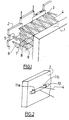
- the winding support 10 also called a pin, is a rod cylindrical. It is fixed to the wall 2 by passing through the two handles 11a, 11b. A reinforcing strip 4 is intended to be wrapped around the pin 10, on a half-turn, as shown in FIG. 2.
- This device 20 comprises a cylindrical bar 21, substantially of same shape as pin 10, forming template for loop configuration 16 and forming the two handles 11a, 11b.
- Two pairs of flanges, or annular flanges, 22a, 23a, 22b, 23b, intended to position the handles 11a, 11b along the template 21, are mounted on the template 21 and integral with it.
- Each handle 11a (11b) is intended for be blocked laterally, along the template 21, between the two flanges 22a, 23a (22b, 23b) of a pair of flanges, the spacing between the two pairs of flanges 22a, 23a, 22b, 23b thus defining the spacing between the two handles 11a, 11b.
- the laying device 20 also includes two spacers 24a, 24b, integral with the template 21, and two clips 25a, intended to press the handles 11a, 11b against the spacers 24a, 24b in order to ensure the parallelism between the branches 13a, 14a, 13b, 14b, handles 11a, 11b, at least a distance equal to the diameter of the pin 10.
- the spacers 24a, 24b are integral with the template 21. Each spacer 24a (24b) extends between the two flanges 22a, 23a (22b, 23b) of a pair of flanges, below the template 21, as shown in Figure 5.
- the two spacers 24a, 24b being identical, only one will now be described.
- the spacer 24a has the overall shape of a rectangular parallelepiped comprising two lateral bearing surfaces 27a, 28a, parallel to the axis longitudinal of the template 21, and an upper surface providing a cavity 28a for receiving the template 21.
- the distance separating the two bearing surfaces 27a, 28a is substantially equal to the distance between the two branches 13a, 14a handle 11a.
- Each clip 25a comprises two support arms 29a, 30a, elastically deformable, extending from each other and provided with two free ends support curved outwards.
- the two support arms 29a, 30a are intended to press the two arms by their curved free ends 13a, 14a of the handle 11a against the two bearing surfaces 27a, 28a of the spacer 24a, in order to ensure parallelism between the two branches 13a, 14a of the handle 11a and to maintain the loop 16 conformed during the installation of the system of attachment.
- the concrete panels constituting the wall 2 are manufactured by flat molding.
- the device When manufacturing a panel, the device is positioned laying 20 above the mold, the spacers 24a, 24b extending below of the template 21, and it blocks the template 21 in rotation. We then take the loop 16, not yet shaped.
- the loop 16 is conformed by applying it against the upper part of the template 21, between the two flanges 22a, 23a a pair of flanges, and against the bearing surfaces 26a, 27a of the spacer 24a.
- the clip 25a is then placed by straddling it on the template 21, by a vertical downward movement between the two flanges 22a, 23a.
- Both arm 29a, 30a of clip 25a press and hold, by their ends free curved, the two branches 13a, 14a of the handle 11a against the two bearing surfaces 26a, 27a of the spacer 24a, thereby ensuring parallelism between the two branches 13a, 14a.
- the clips 25a block handles 11a, 11b and thus prevent any movement of handles 11a, 11b that either up or down.
- the base band, from which the handles 11a, 11b are formed, was implicitly flexible in the description which has just been made. We could imagine a fastening system using a loop of rigid material or semi-rigid.
Abstract
Description
L'invention concerne un système d'attache d'une bande d'armature à une paroi d'un ouvrage de soutènement renforcé. De tels ouvrages de soutènement sont prévus en cas de remblais, voire de déblais, dans le domaine de la construction de routes, de quais, d'autoroutes, de bâtiments et autres réalisations du secteur de bâtiment et des travaux publics.The invention relates to a system for attaching a reinforcing strip to a wall of a reinforced retaining structure. Such works by support are provided in the event of embankment, or even excavation, in the area construction of roads, wharves, highways, buildings and others achievements of the building sector and public works.
Les ouvrages de soutènement renforcé de remblai, ou de déblai, comprennent un mur de parement, généralement en béton, et, entre le massif situé à l'arrière et le mur de parement, un remblai spécifique, en matériau granulaire, renforcé par des bandes d'armature linéaires, s'étendant dans une pluralité de plans horizontaux superposés. Les bandes d'armature de renforcement sont fixées au mur de parement par l'intermédiaire d'un système d'attache.Support structures reinforced with backfill, or cut, include a facing wall, usually concrete, and between the solid located at the rear and the facing wall, a specific embankment, made of material granular, reinforced by linear reinforcing bands, extending in a plurality of superimposed horizontal planes. The reinforcing strips of reinforcement are fixed to the facing wall via a system of attachment.
On connaít un système d'attache comportant une goupille d'enroulement de la bande d'armature, montée dans deux boucles, ou anses, d'attache, en acier plastifié et galvanisé. Les deux anses sont scellées dans le mur de parement et couplées par une tige métallique de liaison, noyée dans le mur, assurant un bon ancrage des anses dans le mur.We know a fastening system comprising a pin winding of the reinforcing strip, mounted in two loops, or handles, of attachment, in plasticized and galvanized steel. The two handles are sealed in the facing wall and coupled by a metal connecting rod, embedded in the wall, ensuring good anchoring of the handles in the wall.
Toutefois, les systèmes d'attache de ce type sont exposés à un risque de corrosion, notamment de la tige de couplage des deux anses.However, fasteners of this type are at risk corrosion, in particular of the coupling rod of the two handles.
La présente invention propose de pallier cet inconvénient.The present invention proposes to overcome this drawback.
A cet effet, l'invention concerne un système d'attache d'une bande d'armature à une paroi d'un ouvrage de soutènement renforcé, comportant un support d'enroulement de la bande d'armature et deux anses de fixation du support d'enroulement à la paroi, caractérisé par le fait que les deux anses sont formées à partir d'une boucle en matériau non corrodable.To this end, the invention relates to a system for attaching a strip. of reinforcement to a wall of a reinforced retaining structure, comprising a support for winding the reinforcing strip and two fixing handles for the winding support on the wall, characterized in that the two handles are formed from a loop of non-corrodible material.
Ainsi, les deux anses se prolongent l'une l'autre de façon continue. La boucle en matériau non corrodable, partiellement noyée dans la paroi, garantit un bon ancrage des anses, sans aucun risque de corrosion.Thus, the two handles extend each other continuously. The loop of non-corrodible material, partially embedded in the wall, guarantees good anchoring of the handles, without any risk of corrosion.
Avantageusement, la boucle est en matériau plastique.Advantageously, the loop is made of plastic material.
La boucle peut comprendre une âme en fibres de polyester, qui assure la résistance mécanique de la bande.The loop may include a polyester fiber core, which provides the mechanical strength of the strip.
De préférence, la boucle comprend une gaine en polyéthylène. Preferably, the loop comprises a polyethylene sheath.
La paroi de l'ouvrage de soutènement, dans laquelle la boucle du système d'attache est partiellement noyée, est généralement en béton. Or, le béton est un milieu alcalin qui risque de détériorer les fibres en polyester. La gaine en polyéthylène permet de protéger l'âme en fibres de polyester.The wall of the retaining structure, in which the loop of the fastening system is partially embedded, is usually made of concrete. However, the concrete is an alkaline medium which can damage polyester fibers. The polyethylene sheath protects the core in polyester fibers.
Avantageusement encore, la boucle est formée à partir d'une bande enroulée sur elle-même.Advantageously also, the loop is formed from a strip rolled up on itself.
De préférence, les anses comprennent les deux extrémités de la bande.Preferably, the handles comprise the two ends of the strip.
Grâce à cela, on évite les risques de détérioration de l'âme en fibres de polyester de la boucle au niveau des deux extrémités de la bande.Thanks to this, the risks of deterioration of the fiber core are avoided. polyester loop at both ends of the band.
L'invention concerne encore un dispositif de pose du système d'attache, explicité ci-dessus, à une paroi d'un ouvrage de soutènement renforcé, comprenant un gabarit de conformation de la boucle et de formation des deux anses.The invention also relates to a device for installing the system. of attachment, explained above, to a wall of a retaining structure reinforced, including a loop shaping and training template of the two handles.
Avantageusement, il est prévu des moyens de positionnement des deux anses le long du gabarit.Advantageously, means are provided for positioning the two handles along the template.
Avantageusement encore, il est prévu des moyens pour assurer le parallélisme entre deux branches de chaque anse.Advantageously also, means are provided to ensure the parallelism between two branches of each handle.
A titre de produit intermédiaire, l'invention concerne également un ensemble de deux anses de fixation pour le système d'attache, explicité plus haut, caractérisé par le fait que les deux anses sont formées à partir d'une boucle en matériau non corrodable.
- L'invention sera mieux comprise à l'aide de la description suivante d'une forme de réalisation particulière du système d'attache et de son dispositif de pose de l'invention, en référence au dessin annexé sur lequel:
- la figure 1 représente une vue en perspective d'un ouvrage de soutènement;
- la figure 2 représente une vue en perspective du système d'attache de l'invention fixé sur une paroi;
- la figure 3 représente une vue en perspective du système d'attache de la figure 2, sans la paroi;
- la figure 4 représente une vue de côté du système d'attache de la figure 2;
- la figure 5 représente une vue en perspective du dispositif de pose du système d'attache de la figure 2 et
- la figure 6 représente une vue en coupe transversale du dispositif de pose de la figure 5, le long de la ligne VI-VI.
- The invention will be better understood using the following description of a particular embodiment of the fastening system and its fitting device of the invention, with reference to the appended drawing in which:
- Figure 1 shows a perspective view of a retaining structure;
- Figure 2 shows a perspective view of the fastening system of the invention fixed to a wall;
- Figure 3 shows a perspective view of the fastening system of Figure 2, without the wall;
- Figure 4 shows a side view of the fastening system of Figure 2;
- FIG. 5 represents a perspective view of the device for fitting the fastening system of FIG. 2 and
- 6 shows a cross-sectional view of the laying device of Figure 5, along the line VI-VI.
Le système d'attache de l'invention est destiné à attacher une bande
d'armature à une paroi de parement d'un ouvrage de soutènement, tel que celui
représenté sur la figure 1. Cet ouvrage, qui soutient un massif 1, comprend,
entre la paroi de parement 2 et le massif 1, un remblai spécifique 3 renforcé
par des bandes d'armatures 4-6, qui s'étendent dans une pluralité de plans
superposés. La paroi 2 est constitué par l'assemblage d'une pluralité de
panneaux. Chaque bande d'armature 4-6 fait des aller-retour, en "zig-zag",
entre une barre de renvoi 7-9, située près du massif 1, et la paroi de parement
2, à laquelle elle est attachée à l'aide du système d'attache qui va maintenant
être décrit.The fastening system of the invention is intended to fasten a strip
of reinforcement to a facing wall of a retaining structure, such as that
represented in FIG. 1. This structure, which supports a massif 1, includes,
between the facing
En référence à la figure 2, le système d'attache comprend un support
10 d'enroulement d'une bande d'armature 4, ou "goupille", et deux anses 11a,
11b de fixation du support d'enroulement 10 à la paroi 2, en saillie hors de la
paroi 2.Referring to Figure 2, the fastening system includes a
Les anses 11a, 11b, perpendiculaires à la paroi 2 et en regard l'une de
l'autre, sont écartées d'une distance inférieure à la longueur de la goupille 10.
Chaque anse 11a (11b) comprend deux branches 13a, 14a (13b, 14b)
sensiblement parallèles et reliées par une partie recourbée 15a (15b). La
distance entre les deux branches 13a, 14a (13b, 14b) d'une anse 11a (11b) est
sensiblement égale au diamètre de la goupille 10. Les deux anses 11a, 11b
sont formées à partir d'une boucle de base 16. Cette boucle 16, mise à plat, a
une forme globalement ovale et comprend deux portions parallèles reliées
entre elles par deux portions de raccordement en "U". Pour former les deux
anses 11a, 11b, les deux portions de raccordement sont relevées, la boucle 16
ayant ainsi globalement, et de façon naturelle, la forme d'une gondole.
Comme on peut le voir sur la figure 4, la boucle 16 est partiellement noyée
dans la paroi 2, dont elle fait saillie par les deux anses 11a, 11b. Celles-ci se
prolongent ainsi l'une l'autre par deux portions de boucle, noyées dans la paroi
2. Grâce au fait que les deux anses font partie d'une même pièce et ne sont
donc pas isolées l'une de l'autre, les portions de boucle, réunissant les deux
anses et noyées dans le béton, assurent une fixation du système d'attache sur
une portion intéressante de la paroi de l'ouvrage de soutènement. Ainsi, les
portions de boucle noyées dans le béton assurent un excellent ancrage des
anses 11a, 11b dans la paroi 2.The
La boucle 16 est formée à partir d'une bande partiellement enroulée
sur elle-même et dont les deux extrémités 17, 18 sont soudées à la bande. La
bande est en matériau plastique non corrodable. Elle comprend une âme en
fibres de polyester, à forte résistance mécanique notamment à la traction,
entourée d'une gaine de protection en polyéthylène. La gaine est destinée à
protéger l'âme en fibres de polyester de l'alcalinité du béton de la paroi 2 et de
l'agressivité du remblai utilisé.The
Les deux anses 11a, 11b comprennent respectivement les deux
extrémités 17, 18 de la bande, qui se trouvent ainsi en dehors de la paroi 2.
Grâce à cela, l'âme de la bande ne risque pas d'être détériorée au niveau des
extrémités 17, 18 du fait de l'alcalinité du béton.The two
Le support d'enroulement 10, encore appelé goupille, est un barreau
cylindrique. Il est fixé à la paroi 2 par passage à travers les deux anses 11a,
11b. Une bande d'armature 4 est destinée à être enroulée autour de la goupille
10, sur un demi-tour, comme représenté sur la figure 2.The
Le dispositif 20 de pose du système d'attache va maintenant être décrit
en référence aux figures 5 et 6.The
Ce dispositif 20 comprend un barreau cylindrique 21, sensiblement de
même forme que la goupille 10, formant gabarit de conformation de la boucle
16 et de formation des deux anses 11a, 11b.This
Deux paires de collerettes, ou flasques annulaires, 22a, 23a, 22b, 23b,
destinées à positionner les anses 11a, 11b le long du gabarit 21, sont montées
sur le gabarit 21 et solidaires de celui-ci. Chaque anse 11a (11b) est destinée à
être bloquée latéralement, le long du gabarit 21, entre les deux flasques 22a,
23a (22b, 23b) d'une paire de flasques, l'écartement entre les deux paires de
flasques 22a, 23a, 22b, 23b définissant ainsi l'écartement entre les deux anses
11a, 11b.Two pairs of flanges, or annular flanges, 22a, 23a, 22b, 23b,
intended to position the
Le dispositif de pose 20 comprend également deux entretoises 24a,
24b, solidaires du gabarit 21, et deux clips 25a, destinées à plaquer les anses
11a, 11b contre les entretoises 24a, 24b afin d'assurer le parallélisme entre les
branches 13a, 14a, 13b, 14b, des anses 11a, 11b, sur une distance au moins
égale au diamètre de la goupille 10.The laying
Les entretoises 24a, 24b sont solidaires du gabarit 21. Chaque
entretoise 24a (24b) s'étend entre les deux flasques 22a, 23a (22b, 23b) d'une
paire de flasques, au-dessous du gabarit 21, comme représenté sur la figure 5.
Les deux entretoises 24a, 24b étant identiques, l'une seule va maintenant être
décrite. L'entretoise 24a a globalement la forme d'un parallélépipède rectangle
comprenant deux surfaces latérales d'appui 27a, 28a, parallèles à l'axe
longitudinal du gabarit 21, et une surface supérieure ménageant une cavité
28a de réception du gabarit 21. La distance séparant les deux surfaces d'appui
27a, 28a est sensiblement égale à la distance entre les deux branches 13a, 14a
de l'anse 11a.The
Chaque clip 25a comprend deux bras d'appui 29a, 30a, élastiquement
déformables, se prolongeant l'un l'autre et pourvus de deux extrémités libres
d'appui recourbées vers l'extérieur. Les deux bras d'appui 29a, 30a sont
destinés à plaquer, par leurs extrémités libres recourbées, les deux branches
13a, 14a de l'anse 11a contre les deux surfaces d'appui 27a, 28a de l'entretoise
24a, afin d'assurer le parallélisme entre les deux branches 13a, 14a de l'anse
11a et de maintenir la boucle 16 conformée lors de la pose du système
d'attache.Each
L'opération de pose du système d'attache précédemment décrit à l'aide
du dispositif de pose 20 va maintenant être explicité.The installation operation of the fastening system previously described using
of the laying
Les panneaux en béton constituant la paroi 2 sont fabriqués par
moulage à plat. Lors de la fabrication d'un panneau, on positionne le dispositif
de pose 20 au-dessus du moule, les entretoises 24a, 24b s'étendant au-dessous
du gabarit 21, et on le bloque en rotation le gabarit 21. On prend ensuite la
boucle 16, non encore conformée.The concrete panels constituting the
Pour former l'anse 11a, on conforme la boucle 16 en l'appliquant
contre la partie supérieure du gabarit 21, entre les deux flasques 22a, 23a
d'une paire de flasques, et contre les surfaces d'appui 26a, 27a de l'entretoise
24a. On pose ensuite le clip 25a en l'enfourchant sur le gabarit 21, par un
mouvement vertical vers le bas, entre les deux flasques 22a, 23a. Les deux
bras 29a, 30a du clip 25a viennent plaquer et maintenir, par leurs-extrémités
libres recourbées, les deux branches 13a, 14a de l'anse 11a contre les deux
surfaces d'appui 26a, 27a de l'entretoise 24a, en assurant ainsi le parallélisme
entre les deux branches 13a, 14a.To form the
On procède de la même manière pour former l'autre anse 11b.We proceed in the same way to form the
Enfin, on coule le béton dans le moule, en noyant partiellement la
boucle 16. Après solidification du béton, on retire le dispositif de pose.Finally, we pour the concrete into the mold, partially submerging the
On soulignera ici que, lors du coulage du béton, les clips 25a bloquent
les anses 11a, 11b et empêchent ainsi tout mouvement des anses 11a, 11b que
ce soit vers le haut ou vers le bas. It will be emphasized here that, during the pouring of the concrete, the
La bande de base, à partir de laquelle on forme les anses 11a, 11b,
était implicitement souple dans la description qui vient d'être faite. On
pourrait imaginer un système d'attache utilisant une boucle en matériau rigide
ou semi-rigide.The base band, from which the
Claims (13)
Applications Claiming Priority (2)
| Application Number | Priority Date | Filing Date | Title |
|---|---|---|---|
| FR0000178A FR2803610B1 (en) | 2000-01-07 | 2000-01-07 | SYSTEM FOR ATTACHING A REINFORCEMENT STRIP TO A WALL OF A SUPPORT STRUCTURE AND DEVICE FOR LAYING SAID SYSTEM |
| FR0000178 | 2000-01-07 |
Publications (2)
| Publication Number | Publication Date |
|---|---|
| EP1114896A1 true EP1114896A1 (en) | 2001-07-11 |
| EP1114896B1 EP1114896B1 (en) | 2005-03-16 |
Family
ID=8845691
Family Applications (1)
| Application Number | Title | Priority Date | Filing Date |
|---|---|---|---|
| EP01400010A Expired - Lifetime EP1114896B1 (en) | 2000-01-07 | 2001-01-04 | System for fastening a reinforcement strip to a retaining wall and apparatus for positioning the system |
Country Status (8)
| Country | Link |
|---|---|
| US (1) | US6447212B2 (en) |
| EP (1) | EP1114896B1 (en) |
| JP (1) | JP4544754B2 (en) |
| AT (1) | ATE291126T1 (en) |
| AU (1) | AU780932B2 (en) |
| DE (1) | DE60109334D1 (en) |
| FR (1) | FR2803610B1 (en) |
| TR (1) | TR200100153A3 (en) |
Cited By (6)
| Publication number | Priority date | Publication date | Assignee | Title |
|---|---|---|---|---|
| FR2860811A1 (en) | 2003-10-13 | 2005-04-15 | Freyssinet Int Stup | REINFORCED GROUND WORK AND METHOD FOR ITS CONSTRUCTION |
| FR2874392A1 (en) * | 2004-08-17 | 2006-02-24 | Dominique Georges Guy Boscher | Modular system for e.g. forming supporting wall, has simple flexible cable that is cast and wind up in facing plate, where cable permits to adjust tension between plates by torsion and rotation on median axis of facing plate |
| WO2007102070A2 (en) * | 2006-03-09 | 2007-09-13 | Terre Armee Internationale | Stabilized soil structure and facing elements for its construction |
| EP2434059A1 (en) | 2010-09-24 | 2012-03-28 | Terre Armée Internationale | A reinforced soil structure |
| EP2434060A1 (en) | 2010-09-24 | 2012-03-28 | Terre Armée Internationale | A reinforced soil structure |
| RU2544346C2 (en) * | 2010-11-26 | 2015-03-20 | Терр Армэ Энтернасьональ | Lining element with its inherent compressibility |
Families Citing this family (21)
| Publication number | Priority date | Publication date | Assignee | Title |
|---|---|---|---|---|
| US6854236B2 (en) | 2001-10-11 | 2005-02-15 | Allan Block Corporation | Reinforcing system for stackable retaining wall units |
| US6792731B2 (en) | 2001-10-11 | 2004-09-21 | Timothy A. Bott | Reinforcing system for stackable retaining wall units |
| KR100660356B1 (en) * | 2004-10-19 | 2006-12-21 | 이정수 | reinforcing strip for supporting reinforced earth wall and its placement method |
| FR2878268B1 (en) * | 2004-11-25 | 2007-02-09 | Freyssinet Internat Stup Soc P | REINFORCED GROUND WORK AND FACING ELEMENTS FOR ITS CONSTRUCTION |
| FR2896520A1 (en) * | 2006-01-23 | 2007-07-27 | Freyssinet Soc Par Actions Sim | ERRIGE WORK IN FRONT OF A PRE-EXISTING WALL, COMPRISING A SIDING AND A FIXTURE BETWEEN THE WALL AND THE SIDING, AND A METHOD FOR CARRYING OUT SAME |
| FR2913436B1 (en) * | 2007-03-05 | 2009-05-29 | Terre Armee Internationale Soc | REINFORCED GROUND WORK AND REINFORCING ELEMENTS FOR ITS CONSTRUCTION |
| US20080292413A1 (en) * | 2007-05-23 | 2008-11-27 | Mateer Stephen A | Cast stone, earthen retaining wall system incorporating geogrid, textile or fabric as the soil reinforcement. |
| US8579552B2 (en) * | 2008-01-24 | 2013-11-12 | Kei-Chien Yu | Ecological board and its applications |
| TW200932998A (en) * | 2008-01-24 | 2009-08-01 | Ke-Jian Yu | Method of forming retaining wall for water and soil conservation and retaining plates |
| US7828498B2 (en) * | 2008-04-02 | 2010-11-09 | Sorheim Daniel R | Connection mechanism for large scale retaining wall blocks |
| FR2939157B1 (en) * | 2008-12-02 | 2013-02-15 | Terre Armee Int | REINFORCED GROUND WORK AND FACING ELEMENTS FOR ITS CONSTRUCTION |
| US20100215442A1 (en) * | 2009-02-26 | 2010-08-26 | Ackerstein Industries | Retaining wall stabilization system |
| FR2948386B1 (en) | 2009-07-22 | 2011-07-29 | Terre Armee Int | BONDING DEVICE FOR STRENGTHENED SOIL WORK, ASSOCIATED WORK AND METHOD |
| PT2550406E (en) * | 2010-03-25 | 2014-03-20 | Terre Armée Internationale | Retaining wall with reinforced earth elements in the backfill |
| US9103089B2 (en) * | 2013-03-15 | 2015-08-11 | Tricon Precast, Ltd. | Loop and saddle connection system and method for mechanically stablized earth wall |
| US20140345220A1 (en) | 2013-05-24 | 2014-11-27 | Francesco Ferraiolo | Anchoring system for concrete panels in a stabilized earth structure |
| FR3010423B1 (en) | 2013-09-09 | 2016-02-19 | Soletanche Freyssinet | GEOTECHNIC ANCHORING ATTACHMENT SYSTEM AND REINFORCEMENT ASSEMBLY USING SUCH A TIE. |
| US20150078838A1 (en) * | 2013-09-18 | 2015-03-19 | Kenneth Shaw | Horizontal connection for mechanically stabilized earth walls |
| US10161099B2 (en) * | 2014-12-22 | 2018-12-25 | Tricon Precast, Ltd. | Geosynthetic connection systems and methods for mechanically stablized earth walls |
| JP5931307B1 (en) * | 2016-01-26 | 2016-06-08 | 株式会社山源 | Water stop device |
| US11174615B2 (en) * | 2019-05-07 | 2021-11-16 | E.C. Manufacturing, LLC | Landscaping walls, systems and methods |
Citations (4)
| Publication number | Priority date | Publication date | Assignee | Title |
|---|---|---|---|---|
| US4343571A (en) * | 1978-07-13 | 1982-08-10 | Soil Structures International Limited | Reinforced earth structures |
| WO1984002510A1 (en) * | 1982-12-21 | 1984-07-05 | Shiraijitsugyo Co Ltd | Belt-shaped fiber sling |
| US5624211A (en) * | 1993-03-31 | 1997-04-29 | Societe Civile Des Brevets Henri C. Vidal | Modular block retaining wall construction and components |
| WO1998006907A1 (en) * | 1996-08-09 | 1998-02-19 | Derrick Ian Peter Price | Soil reinforcement |
Family Cites Families (13)
| Publication number | Priority date | Publication date | Assignee | Title |
|---|---|---|---|---|
| GB1050789A (en) * | 1900-01-01 | |||
| DE2753243A1 (en) * | 1977-11-29 | 1979-06-07 | Bayer Ag | REINFORCEMENT OF REINFORCED EARTH STRUCTURES |
| JPS55144116A (en) * | 1979-04-28 | 1980-11-10 | Hirose Kozai Sangyo | Flask device for manufacturing concrete block |
| EP0130949A3 (en) * | 1983-06-28 | 1985-11-27 | Luciano Sangiorgio | Concrete panels and relative means for their anchoring to earth, for forming a facing wall of variable planimetric course and allowing settlement of the panels in the facing wall surface, and the facing wall thus obtained |
| DE4131956A1 (en) * | 1991-09-25 | 1993-04-01 | Philipp Gmbh Geb | ROPE LOOP INSERT FOR THE COMPOSITION OF PRECAST CONCRETE PARTS |
| US5507599A (en) * | 1993-03-31 | 1996-04-16 | Societe Civile Des Brevets Henri C. Vidal | Modular block retaining wall construction and components |
| US5568998A (en) * | 1995-02-14 | 1996-10-29 | The Tensar Corporation | Precast wall panel and grid connection device |
| JPH08302693A (en) * | 1995-05-11 | 1996-11-19 | Maeda Kousen Kk | Reinforcing earthwork method |
| JPH09165762A (en) * | 1995-08-18 | 1997-06-24 | Soc Civile Des Brevets De Henri Vidal | Surface coating element of stabilized banking structure |
| JPH1060896A (en) * | 1996-08-22 | 1998-03-03 | Kyokado Eng Co Ltd | Wall surface structure of reinforced earth structure |
| FR2773372B1 (en) * | 1998-01-07 | 2000-03-24 | Freyssinet Int Stup | SYSTEM FOR ATTACHING A REINFORCEMENT STRIP TO A WALL OF A REINFORCED SUPPORT STRUCTURE AND METHOD OF MANUFACTURING THE WALL |
| US6186703B1 (en) * | 1998-03-12 | 2001-02-13 | Shaw Technologies | Mechanical interlocking means for retaining wall |
| US5975810A (en) * | 1998-04-01 | 1999-11-02 | Taylor; Thomas P. | Geo-grid anchor |
-
2000
- 2000-01-07 FR FR0000178A patent/FR2803610B1/en not_active Expired - Fee Related
-
2001
- 2001-01-04 EP EP01400010A patent/EP1114896B1/en not_active Expired - Lifetime
- 2001-01-04 AT AT01400010T patent/ATE291126T1/en not_active IP Right Cessation
- 2001-01-04 DE DE60109334T patent/DE60109334D1/en not_active Expired - Lifetime
- 2001-01-05 TR TR2001/00153A patent/TR200100153A3/en unknown
- 2001-01-05 AU AU11085/01A patent/AU780932B2/en not_active Ceased
- 2001-01-08 US US09/756,091 patent/US6447212B2/en not_active Expired - Fee Related
- 2001-01-09 JP JP2001001400A patent/JP4544754B2/en not_active Expired - Lifetime
Patent Citations (4)
| Publication number | Priority date | Publication date | Assignee | Title |
|---|---|---|---|---|
| US4343571A (en) * | 1978-07-13 | 1982-08-10 | Soil Structures International Limited | Reinforced earth structures |
| WO1984002510A1 (en) * | 1982-12-21 | 1984-07-05 | Shiraijitsugyo Co Ltd | Belt-shaped fiber sling |
| US5624211A (en) * | 1993-03-31 | 1997-04-29 | Societe Civile Des Brevets Henri C. Vidal | Modular block retaining wall construction and components |
| WO1998006907A1 (en) * | 1996-08-09 | 1998-02-19 | Derrick Ian Peter Price | Soil reinforcement |
Cited By (15)
| Publication number | Priority date | Publication date | Assignee | Title |
|---|---|---|---|---|
| WO2005040506A1 (en) | 2003-10-13 | 2005-05-06 | Freyssinet | Reinforced soil structure and method for constructing it |
| FR2860811A1 (en) | 2003-10-13 | 2005-04-15 | Freyssinet Int Stup | REINFORCED GROUND WORK AND METHOD FOR ITS CONSTRUCTION |
| FR2874392A1 (en) * | 2004-08-17 | 2006-02-24 | Dominique Georges Guy Boscher | Modular system for e.g. forming supporting wall, has simple flexible cable that is cast and wind up in facing plate, where cable permits to adjust tension between plates by torsion and rotation on median axis of facing plate |
| US7850400B2 (en) | 2004-11-25 | 2010-12-14 | Freyssinet International (Stup) | Stabilized soil structure and facing elements for its construction |
| US8152417B2 (en) | 2004-11-25 | 2012-04-10 | Terre Armee Internationale | Stabilized soil structure and facing elements for its construction |
| WO2007102070A2 (en) * | 2006-03-09 | 2007-09-13 | Terre Armee Internationale | Stabilized soil structure and facing elements for its construction |
| EA013729B1 (en) * | 2006-03-09 | 2010-06-30 | Терр Арме Энтернасьональ | Stabilized soil structure and facing elements for its construction |
| CN101400861B (en) * | 2006-03-09 | 2011-01-19 | 泰瑞埃米国际公司 | Stabilized soil structure and facing elements for its construction |
| WO2007102070A3 (en) * | 2006-03-09 | 2007-11-22 | Terre Armee Int | Stabilized soil structure and facing elements for its construction |
| HRP20080424B1 (en) * | 2006-03-09 | 2017-02-10 | Terre Armee Internationale | Stabilized soil structure and facing elements for its construction |
| EP2434059A1 (en) | 2010-09-24 | 2012-03-28 | Terre Armée Internationale | A reinforced soil structure |
| EP2434060A1 (en) | 2010-09-24 | 2012-03-28 | Terre Armée Internationale | A reinforced soil structure |
| WO2012038549A1 (en) | 2010-09-24 | 2012-03-29 | Terre Armee Internationale | A reinforced soil structure |
| US9080303B2 (en) | 2010-09-24 | 2015-07-14 | Terre Armee Internationale | Reinforced soil structure |
| RU2544346C2 (en) * | 2010-11-26 | 2015-03-20 | Терр Армэ Энтернасьональ | Lining element with its inherent compressibility |
Also Published As
| Publication number | Publication date |
|---|---|
| AU1108501A (en) | 2001-07-12 |
| FR2803610A1 (en) | 2001-07-13 |
| US20010014255A1 (en) | 2001-08-16 |
| ATE291126T1 (en) | 2005-04-15 |
| FR2803610B1 (en) | 2002-09-27 |
| AU780932B2 (en) | 2005-04-28 |
| JP2001226969A (en) | 2001-08-24 |
| TR200100153A2 (en) | 2001-08-21 |
| DE60109334D1 (en) | 2005-04-21 |
| JP4544754B2 (en) | 2010-09-15 |
| EP1114896B1 (en) | 2005-03-16 |
| TR200100153A3 (en) | 2001-08-21 |
| US6447212B2 (en) | 2002-09-10 |
Similar Documents
| Publication | Publication Date | Title |
|---|---|---|
| EP1114896B1 (en) | System for fastening a reinforcement strip to a retaining wall and apparatus for positioning the system | |
| CA2515316C (en) | Reinforced in-ground structure and facing elements for its construction | |
| EP0188487B1 (en) | Large cross-section sunken conduit | |
| CA2768945C (en) | Connection device for a reinforced earth structure, and related structure and method | |
| WO2002075069A1 (en) | Device for anchoring prestressing reinforcements, prestressing system including said device and corresponding reinforcement | |
| WO2011117476A1 (en) | Building with reinforced ground | |
| EP0003087B1 (en) | Device for connecting elongated elements of a reinforced concrete framework and framework comprising elements connected by such a device. | |
| WO2015019017A2 (en) | Sealing device and structure for a reinforced concrete element comprising said device | |
| FR2721988A1 (en) | FLUID CIRCULATION DUCT | |
| EP1376808A1 (en) | Device for fixing a cable conduit on a support and arrangement comprising a conduit and such a device | |
| FR2584440A1 (en) | Socket for positioning a pipe during the pouring of reinforced concrete | |
| FR2929628A1 (en) | STABILIZATION REINFORCEMENT FOR USE IN REINFORCED GROUND WORKS | |
| FR2737515A1 (en) | Support and concrete form work for underground electrical and telephone cables - has lateral form work with transverse duct support plates at regular intervals along length, with both assembled by stacking strips edge to edge | |
| CH653725A5 (en) | Building machine for laying and coating pipes | |
| EP0952307B1 (en) | Method for the construction of a structure under an embankment supporting a railway track or a roadway | |
| FR2600698A2 (en) | Device for stopping and support intended to be driven into the ground by hammering in order to form plant-training assemblies, fences, etc | |
| FR2649434A1 (en) | Device for forming cornices on a wall | |
| EP0672856A1 (en) | Prefabricated yoke for stabilizing a pipeline, method for stabilization and its application | |
| FR2997423A1 (en) | Level crossing device for facilitating movement of road vehicles through railway, has immobilizing unit including rigid flexible tension metal cable with two ends fastened on two free end faces of inner reinforced concrete slabs | |
| CH660618A5 (en) | Device for guiding tubes and/or pipes coming out of concrete slabs and its use | |
| FR2705426A1 (en) | Device for unrolling (paying out) buried piping | |
| FR2870871A1 (en) | Console lifting device for building, has assembly with pulley and blocker fixed with cross bar of console for lifting console along rope, where blocker prevents release of strand of rope at pulley to maintain console at height | |
| WO2001068987A1 (en) | Method for reinforcing a cable carrying a civil engineering suspended structure | |
| FR3098533A1 (en) | Lifting anchor, wall with integrated formwork incorporating said lifting anchor, and method of manufacturing said lifting anchor | |
| FR2657639A1 (en) | METHOD FOR FORMING A WALL MOLDED CONCRETE WALL IN A TRENCH AND FORMWORK FOR CARRYING OUT SAID METHOD |
Legal Events
| Date | Code | Title | Description |
|---|---|---|---|
| PUAI | Public reference made under article 153(3) epc to a published international application that has entered the european phase |
Free format text: ORIGINAL CODE: 0009012 |
|
| AK | Designated contracting states |
Kind code of ref document: A1 Designated state(s): AT BE CH CY DE DK ES FI FR GB GR IE IT LI LU MC NL PT SE TR |
|
| AX | Request for extension of the european patent |
Free format text: AL;LT;LV;MK;RO;SI |
|
| 17P | Request for examination filed |
Effective date: 20020111 |
|
| AKX | Designation fees paid |
Free format text: AT BE CH CY DE DK ES FI FR GB GR IE IT LI LU MC NL PT SE TR |
|
| 17Q | First examination report despatched |
Effective date: 20031008 |
|
| GRAP | Despatch of communication of intention to grant a patent |
Free format text: ORIGINAL CODE: EPIDOSNIGR1 |
|
| GRAS | Grant fee paid |
Free format text: ORIGINAL CODE: EPIDOSNIGR3 |
|
| GRAA | (expected) grant |
Free format text: ORIGINAL CODE: 0009210 |
|
| AK | Designated contracting states |
Kind code of ref document: B1 Designated state(s): AT BE CH CY DE DK ES FI FR GB GR IE IT LI LU MC NL PT SE TR |
|
| PG25 | Lapsed in a contracting state [announced via postgrant information from national office to epo] |
Ref country code: IT Free format text: LAPSE BECAUSE OF FAILURE TO SUBMIT A TRANSLATION OF THE DESCRIPTION OR TO PAY THE FEE WITHIN THE PRESCRIBED TIME-LIMIT;WARNING: LAPSES OF ITALIAN PATENTS WITH EFFECTIVE DATE BEFORE 2007 MAY HAVE OCCURRED AT ANY TIME BEFORE 2007. THE CORRECT EFFECTIVE DATE MAY BE DIFFERENT FROM THE ONE RECORDED. Effective date: 20050316 Ref country code: FI Free format text: LAPSE BECAUSE OF FAILURE TO SUBMIT A TRANSLATION OF THE DESCRIPTION OR TO PAY THE FEE WITHIN THE PRESCRIBED TIME-LIMIT Effective date: 20050316 Ref country code: AT Free format text: LAPSE BECAUSE OF FAILURE TO SUBMIT A TRANSLATION OF THE DESCRIPTION OR TO PAY THE FEE WITHIN THE PRESCRIBED TIME-LIMIT Effective date: 20050316 Ref country code: NL Free format text: LAPSE BECAUSE OF FAILURE TO SUBMIT A TRANSLATION OF THE DESCRIPTION OR TO PAY THE FEE WITHIN THE PRESCRIBED TIME-LIMIT Effective date: 20050316 Ref country code: IE Free format text: LAPSE BECAUSE OF FAILURE TO SUBMIT A TRANSLATION OF THE DESCRIPTION OR TO PAY THE FEE WITHIN THE PRESCRIBED TIME-LIMIT Effective date: 20050316 Ref country code: GB Free format text: LAPSE BECAUSE OF FAILURE TO SUBMIT A TRANSLATION OF THE DESCRIPTION OR TO PAY THE FEE WITHIN THE PRESCRIBED TIME-LIMIT Effective date: 20050316 |
|
| REG | Reference to a national code |
Ref country code: GB Ref legal event code: FG4D Free format text: NOT ENGLISH |
|
| REG | Reference to a national code |
Ref country code: CH Ref legal event code: EP |
|
| REG | Reference to a national code |
Ref country code: IE Ref legal event code: FG4D Free format text: FRENCH |
|
| REF | Corresponds to: |
Ref document number: 60109334 Country of ref document: DE Date of ref document: 20050421 Kind code of ref document: P |
|
| PG25 | Lapsed in a contracting state [announced via postgrant information from national office to epo] |
Ref country code: DK Free format text: LAPSE BECAUSE OF FAILURE TO SUBMIT A TRANSLATION OF THE DESCRIPTION OR TO PAY THE FEE WITHIN THE PRESCRIBED TIME-LIMIT Effective date: 20050616 Ref country code: GR Free format text: LAPSE BECAUSE OF FAILURE TO SUBMIT A TRANSLATION OF THE DESCRIPTION OR TO PAY THE FEE WITHIN THE PRESCRIBED TIME-LIMIT Effective date: 20050616 |
|
| PG25 | Lapsed in a contracting state [announced via postgrant information from national office to epo] |
Ref country code: DE Free format text: LAPSE BECAUSE OF FAILURE TO SUBMIT A TRANSLATION OF THE DESCRIPTION OR TO PAY THE FEE WITHIN THE PRESCRIBED TIME-LIMIT Effective date: 20050617 |
|
| PG25 | Lapsed in a contracting state [announced via postgrant information from national office to epo] |
Ref country code: ES Free format text: LAPSE BECAUSE OF FAILURE TO SUBMIT A TRANSLATION OF THE DESCRIPTION OR TO PAY THE FEE WITHIN THE PRESCRIBED TIME-LIMIT Effective date: 20050627 |
|
| NLV1 | Nl: lapsed or annulled due to failure to fulfill the requirements of art. 29p and 29m of the patents act | ||
| PG25 | Lapsed in a contracting state [announced via postgrant information from national office to epo] |
Ref country code: PT Free format text: LAPSE BECAUSE OF FAILURE TO SUBMIT A TRANSLATION OF THE DESCRIPTION OR TO PAY THE FEE WITHIN THE PRESCRIBED TIME-LIMIT Effective date: 20050907 |
|
| GBV | Gb: ep patent (uk) treated as always having been void in accordance with gb section 77(7)/1977 [no translation filed] |
Effective date: 20050316 |
|
| REG | Reference to a national code |
Ref country code: IE Ref legal event code: FD4D |
|
| PLBE | No opposition filed within time limit |
Free format text: ORIGINAL CODE: 0009261 |
|
| STAA | Information on the status of an ep patent application or granted ep patent |
Free format text: STATUS: NO OPPOSITION FILED WITHIN TIME LIMIT |
|
| PG25 | Lapsed in a contracting state [announced via postgrant information from national office to epo] |
Ref country code: BE Free format text: LAPSE BECAUSE OF NON-PAYMENT OF DUE FEES Effective date: 20060131 Ref country code: FR Free format text: LAPSE BECAUSE OF NON-PAYMENT OF DUE FEES Effective date: 20060131 Ref country code: LI Free format text: LAPSE BECAUSE OF NON-PAYMENT OF DUE FEES Effective date: 20060131 Ref country code: MC Free format text: LAPSE BECAUSE OF NON-PAYMENT OF DUE FEES Effective date: 20060131 Ref country code: LU Free format text: LAPSE BECAUSE OF NON-PAYMENT OF DUE FEES Effective date: 20060131 Ref country code: CH Free format text: LAPSE BECAUSE OF NON-PAYMENT OF DUE FEES Effective date: 20060131 |
|
| 26N | No opposition filed |
Effective date: 20051219 |
|
| REG | Reference to a national code |
Ref country code: CH Ref legal event code: PL |
|
| REG | Reference to a national code |
Ref country code: FR Ref legal event code: ST Effective date: 20060929 |
|
| BERE | Be: lapsed |
Owner name: FREYSSINET INTERNATIONAL (STUP) Effective date: 20060131 |
|
| PG25 | Lapsed in a contracting state [announced via postgrant information from national office to epo] |
Ref country code: SE Free format text: LAPSE BECAUSE OF FAILURE TO SUBMIT A TRANSLATION OF THE DESCRIPTION OR TO PAY THE FEE WITHIN THE PRESCRIBED TIME-LIMIT Effective date: 20050616 |
|
| PG25 | Lapsed in a contracting state [announced via postgrant information from national office to epo] |
Ref country code: TR Free format text: LAPSE BECAUSE OF FAILURE TO SUBMIT A TRANSLATION OF THE DESCRIPTION OR TO PAY THE FEE WITHIN THE PRESCRIBED TIME-LIMIT Effective date: 20050316 |
|
| PG25 | Lapsed in a contracting state [announced via postgrant information from national office to epo] |
Ref country code: CY Free format text: LAPSE BECAUSE OF FAILURE TO SUBMIT A TRANSLATION OF THE DESCRIPTION OR TO PAY THE FEE WITHIN THE PRESCRIBED TIME-LIMIT Effective date: 20050316 |