EP1114302B1 - Temporal artery temperature detection - Google Patents
Temporal artery temperature detection Download PDFInfo
- Publication number
- EP1114302B1 EP1114302B1 EP99945647A EP99945647A EP1114302B1 EP 1114302 B1 EP1114302 B1 EP 1114302B1 EP 99945647 A EP99945647 A EP 99945647A EP 99945647 A EP99945647 A EP 99945647A EP 1114302 B1 EP1114302 B1 EP 1114302B1
- Authority
- EP
- European Patent Office
- Prior art keywords
- temperature
- detector
- temporal artery
- ambient
- artery
- Prior art date
- Legal status (The legal status is an assumption and is not a legal conclusion. Google has not performed a legal analysis and makes no representation as to the accuracy of the status listed.)
- Expired - Lifetime
Links
- 210000001994 temporal artery Anatomy 0.000 title claims description 25
- 238000001514 detection method Methods 0.000 title description 4
- 230000005855 radiation Effects 0.000 claims abstract description 25
- 238000000034 method Methods 0.000 claims abstract description 22
- 210000001061 forehead Anatomy 0.000 claims abstract description 19
- 210000001367 artery Anatomy 0.000 claims abstract description 14
- 230000036760 body temperature Effects 0.000 claims abstract description 14
- 238000012545 processing Methods 0.000 claims abstract description 4
- 230000008569 process Effects 0.000 claims abstract description 3
- 239000008280 blood Substances 0.000 claims description 12
- 210000004369 blood Anatomy 0.000 claims description 12
- 230000010412 perfusion Effects 0.000 claims description 12
- 238000012546 transfer Methods 0.000 claims description 5
- 239000000463 material Substances 0.000 claims description 3
- 210000001519 tissue Anatomy 0.000 description 7
- 210000001099 axilla Anatomy 0.000 description 6
- 238000013461 design Methods 0.000 description 6
- 230000035939 shock Effects 0.000 description 6
- 230000017531 blood circulation Effects 0.000 description 5
- 230000008859 change Effects 0.000 description 5
- 238000005259 measurement Methods 0.000 description 5
- 210000001147 pulmonary artery Anatomy 0.000 description 5
- 238000009529 body temperature measurement Methods 0.000 description 4
- 210000000613 ear canal Anatomy 0.000 description 4
- 210000003128 head Anatomy 0.000 description 4
- 238000013459 approach Methods 0.000 description 3
- 238000001816 cooling Methods 0.000 description 3
- 230000000717 retained effect Effects 0.000 description 3
- 210000003625 skull Anatomy 0.000 description 3
- PXHVJJICTQNCMI-UHFFFAOYSA-N Nickel Chemical compound [Ni] PXHVJJICTQNCMI-UHFFFAOYSA-N 0.000 description 2
- 229910052782 aluminium Inorganic materials 0.000 description 2
- XAGFODPZIPBFFR-UHFFFAOYSA-N aluminium Chemical compound [Al] XAGFODPZIPBFFR-UHFFFAOYSA-N 0.000 description 2
- 210000000709 aorta Anatomy 0.000 description 2
- 238000004364 calculation method Methods 0.000 description 2
- 238000012864 cross contamination Methods 0.000 description 2
- 238000010586 diagram Methods 0.000 description 2
- 210000003414 extremity Anatomy 0.000 description 2
- 238000004861 thermometry Methods 0.000 description 2
- YMHOBZXQZVXHBM-UHFFFAOYSA-N 2,5-dimethoxy-4-bromophenethylamine Chemical compound COC1=CC(CCN)=C(OC)C=C1Br YMHOBZXQZVXHBM-UHFFFAOYSA-N 0.000 description 1
- 229910001369 Brass Inorganic materials 0.000 description 1
- 206010037660 Pyrexia Diseases 0.000 description 1
- 206010047139 Vasoconstriction Diseases 0.000 description 1
- 241000545067 Venus Species 0.000 description 1
- 208000027418 Wounds and injury Diseases 0.000 description 1
- 230000004913 activation Effects 0.000 description 1
- 230000003872 anastomosis Effects 0.000 description 1
- 210000003423 ankle Anatomy 0.000 description 1
- 230000004888 barrier function Effects 0.000 description 1
- 230000033228 biological regulation Effects 0.000 description 1
- 230000036770 blood supply Effects 0.000 description 1
- 210000004556 brain Anatomy 0.000 description 1
- 239000010951 brass Substances 0.000 description 1
- 210000001168 carotid artery common Anatomy 0.000 description 1
- 238000006243 chemical reaction Methods 0.000 description 1
- 230000004087 circulation Effects 0.000 description 1
- 238000004891 communication Methods 0.000 description 1
- 239000004020 conductor Substances 0.000 description 1
- 230000006378 damage Effects 0.000 description 1
- 230000007423 decrease Effects 0.000 description 1
- 230000003247 decreasing effect Effects 0.000 description 1
- 230000001419 dependent effect Effects 0.000 description 1
- 230000010259 detection of temperature stimulus Effects 0.000 description 1
- 210000005069 ears Anatomy 0.000 description 1
- 229920001971 elastomer Polymers 0.000 description 1
- 239000000806 elastomer Substances 0.000 description 1
- 238000001704 evaporation Methods 0.000 description 1
- 230000008020 evaporation Effects 0.000 description 1
- 210000004709 eyebrow Anatomy 0.000 description 1
- 230000004907 flux Effects 0.000 description 1
- 208000014674 injury Diseases 0.000 description 1
- 239000012774 insulation material Substances 0.000 description 1
- 238000002955 isolation Methods 0.000 description 1
- 239000004973 liquid crystal related substance Substances 0.000 description 1
- 210000004072 lung Anatomy 0.000 description 1
- 229910052751 metal Inorganic materials 0.000 description 1
- 239000002184 metal Substances 0.000 description 1
- 210000004400 mucous membrane Anatomy 0.000 description 1
- 229910052759 nickel Inorganic materials 0.000 description 1
- 210000000056 organ Anatomy 0.000 description 1
- 210000000664 rectum Anatomy 0.000 description 1
- 230000004044 response Effects 0.000 description 1
- 239000000523 sample Substances 0.000 description 1
- 238000012216 screening Methods 0.000 description 1
- 239000004065 semiconductor Substances 0.000 description 1
- 239000007779 soft material Substances 0.000 description 1
- 210000003454 tympanic membrane Anatomy 0.000 description 1
- 230000025033 vasoconstriction Effects 0.000 description 1
- 230000001457 vasomotor Effects 0.000 description 1
- 210000003462 vein Anatomy 0.000 description 1
- 210000000707 wrist Anatomy 0.000 description 1
- 229910052724 xenon Inorganic materials 0.000 description 1
- FHNFHKCVQCLJFQ-UHFFFAOYSA-N xenon atom Chemical compound [Xe] FHNFHKCVQCLJFQ-UHFFFAOYSA-N 0.000 description 1
Images


Classifications
-
- A—HUMAN NECESSITIES
- A61—MEDICAL OR VETERINARY SCIENCE; HYGIENE
- A61B—DIAGNOSIS; SURGERY; IDENTIFICATION
- A61B5/00—Measuring for diagnostic purposes; Identification of persons
- A61B5/01—Measuring temperature of body parts ; Diagnostic temperature sensing, e.g. for malignant or inflamed tissue
- A61B5/015—By temperature mapping of body part
-
- A—HUMAN NECESSITIES
- A61—MEDICAL OR VETERINARY SCIENCE; HYGIENE
- A61B—DIAGNOSIS; SURGERY; IDENTIFICATION
- A61B5/00—Measuring for diagnostic purposes; Identification of persons
- A61B5/74—Details of notification to user or communication with user or patient ; user input means
- A61B5/742—Details of notification to user or communication with user or patient ; user input means using visual displays
-
- G—PHYSICS
- G01—MEASURING; TESTING
- G01J—MEASUREMENT OF INTENSITY, VELOCITY, SPECTRAL CONTENT, POLARISATION, PHASE OR PULSE CHARACTERISTICS OF INFRARED, VISIBLE OR ULTRAVIOLET LIGHT; COLORIMETRY; RADIATION PYROMETRY
- G01J5/00—Radiation pyrometry, e.g. infrared or optical thermometry
- G01J5/0022—Radiation pyrometry, e.g. infrared or optical thermometry for sensing the radiation of moving bodies
- G01J5/0025—Living bodies
-
- G—PHYSICS
- G01—MEASURING; TESTING
- G01J—MEASUREMENT OF INTENSITY, VELOCITY, SPECTRAL CONTENT, POLARISATION, PHASE OR PULSE CHARACTERISTICS OF INFRARED, VISIBLE OR ULTRAVIOLET LIGHT; COLORIMETRY; RADIATION PYROMETRY
- G01J5/00—Radiation pyrometry, e.g. infrared or optical thermometry
- G01J5/02—Constructional details
- G01J5/026—Control of working procedures of a pyrometer, other than calibration; Bandwidth calculation; Gain control
-
- G—PHYSICS
- G01—MEASURING; TESTING
- G01J—MEASUREMENT OF INTENSITY, VELOCITY, SPECTRAL CONTENT, POLARISATION, PHASE OR PULSE CHARACTERISTICS OF INFRARED, VISIBLE OR ULTRAVIOLET LIGHT; COLORIMETRY; RADIATION PYROMETRY
- G01J5/00—Radiation pyrometry, e.g. infrared or optical thermometry
- G01J5/02—Constructional details
- G01J5/04—Casings
-
- G—PHYSICS
- G01—MEASURING; TESTING
- G01J—MEASUREMENT OF INTENSITY, VELOCITY, SPECTRAL CONTENT, POLARISATION, PHASE OR PULSE CHARACTERISTICS OF INFRARED, VISIBLE OR ULTRAVIOLET LIGHT; COLORIMETRY; RADIATION PYROMETRY
- G01J5/00—Radiation pyrometry, e.g. infrared or optical thermometry
- G01J5/02—Constructional details
- G01J5/05—Means for preventing contamination of the components of the optical system; Means for preventing obstruction of the radiation path
-
- G—PHYSICS
- G01—MEASURING; TESTING
- G01J—MEASUREMENT OF INTENSITY, VELOCITY, SPECTRAL CONTENT, POLARISATION, PHASE OR PULSE CHARACTERISTICS OF INFRARED, VISIBLE OR ULTRAVIOLET LIGHT; COLORIMETRY; RADIATION PYROMETRY
- G01J5/00—Radiation pyrometry, e.g. infrared or optical thermometry
- G01J5/02—Constructional details
- G01J5/06—Arrangements for eliminating effects of disturbing radiation; Arrangements for compensating changes in sensitivity
-
- G—PHYSICS
- G01—MEASURING; TESTING
- G01J—MEASUREMENT OF INTENSITY, VELOCITY, SPECTRAL CONTENT, POLARISATION, PHASE OR PULSE CHARACTERISTICS OF INFRARED, VISIBLE OR ULTRAVIOLET LIGHT; COLORIMETRY; RADIATION PYROMETRY
- G01J5/00—Radiation pyrometry, e.g. infrared or optical thermometry
- G01J5/10—Radiation pyrometry, e.g. infrared or optical thermometry using electric radiation detectors
- G01J5/12—Radiation pyrometry, e.g. infrared or optical thermometry using electric radiation detectors using thermoelectric elements, e.g. thermocouples
- G01J5/14—Electrical features thereof
- G01J5/16—Arrangements with respect to the cold junction; Compensating influence of ambient temperature or other variables
Definitions
- thermometers have come into wide use for detection of temperature of adults.
- infrared thermometers which are adapted to be inserted into the patient's ear have been very successful.
- Early infrared thermometers were adapted to extend into the ear canal in order to view the tympanic membrane and provide an uncorrected, direct reading of tympanic temperature which correlates with pulmonary artery temperature.
- ear thermometers have been designed to provide corrected readings of the generally cooler distal ear canal. Such thermometers measure temperature of distal ear canal tissue and calculate arterial core temperature via heat balance.
- Core temperature is a term used to describe deep body temperature and is approximated by oral, rectal, ear, pulmonary artery, esophageal and bladder temperatures and the like. Of those temperatures, pulmonary artery temperature is the most precise definition of core temperature since it is closest to the heart and its blood is supplied to all tissues. Calculations of arterial core temperature via heat balance provide approximations of the pulmonary artery temperature, and unless otherwise indicated, core temperature refers to the pulmonary artery temperature.
- the arterial heat balance approach is based on a model of heat flow through series thermal resistances from the arterial core temperature to the ear skin temperature and from the ear skin temperature to ambient temperature. Accordingly, after sensing both the skin temperature and ambient temperature, the arterial core temperature can be calculated.
- the thermal resistance model also allows for computation of equivalent oral and rectal temperatures with the mere adjustment of a weighting factor in the computation.
- Infrared ear thermometers using the arterial heat balance are disclosed in U.S. Patents 4,993,419 ; 5,012,813 ; 5,199,436 ; 5,381,796 ; 5,445,158 ; 5,653,238 and 5,271,407 .
- thermometers To avoid clinical difficulties in using ear thermometers, particularly with neonates, axillary (underarm) infrared thermometers have been introduced. Infrared thermometers designed for axillary temperature measurements are presented in U.S. Patent Applications Serial Nos. 08/469,484 , 08/738,300 and 08/881,891 .
- an infrared detector probe extends from a temperature display housing and may easily slide into the axilla to lightly touch the apex of the axilla and provide an accurate infrared temperature reading in as little as one-half second.
- the axillary thermometer also relies on the arterial heat balance approach to provide arterial, oral or rectal temperature.
- thermometer has found great utility not only with neonates but as a screening tool in general, and especially for small children where conventional temperature measurements such as a thermometer under the tongue or a rectal thermometer are difficult.
- h is an empirically determined coefficient which includes a radiation view factor between the skin tissue and ambient
- p is perfusion rate
- c is blood specific heat.
- h is an empirically determined coefficient which includes a radiation view factor between the skin tissue and ambient
- p is perfusion rate
- c is blood specific heat.
- that coefficient was found empirically to be about .09 and .05, respectively, with only minor variations.
- that coefficient has been determined empirically for the adult axillary region to be about .13 with much more significant variations according to the patent's temperature.
- U.S. Patent 4,302,971 describes a method of detecting human body temperature by locating a temperature detector across a region of a forehead to measure a skin temperature over a superior orbital artery and computing a body temperature as a function of said measured temperature.
- the problem solved by the present invention consists in increasing the detection accuracy.
- Embodiments of the present invention provide for particularly convenient temperature readings of neonate, child and adult temperatures by detecting the temperature of the forehead directly over the superficial temporal artery.
- arteries receive blood directly from the heart, they are a good choice for detecting core temperature, but an artery at the extremities of the body, such as those felt as pulse points at the wrist or ankle, are highly subject to vasoconstriction. This means, for example, that when an individual is extremely sick, in shock, or even just cold or nervous, the arteries constrict to reduce the flow of blood to that area as a means of retaining heat, or as in the case of shock, in an effort to redirect the blood to more critical areas of the body. This can result in a large temperature change at the artery which is a local artifact only and not representative of core temperature.
- aorta Originating in the heart is the aorta, the main trunk of the arterial system.
- a direct extension of the aorta is the common carotid artery, a robust artery which runs upward in the neck and divides into the internal and external carotids. But, the carotids, even the external carotid, are at best partially embedded, and at worst completely embedded in the skull, and therefore are not accessible at the skin.
- Extending directly from the carotid is the temporal artery, again an artery dividing internally and externally. We look to the external branch which travels in front of the ear and up into the soft temple area, terminating in a fork directly between the skin and the skull adjoining the eyebrow.
- the temporal artery is very easily accessible; in fact in most individuals, it is usually quite visible. Terminating in a two-prong fork, it easily doubles the assurance of measuring the correct area. Touching it does not present a risk of injury. There are no mucous membranes present, thus eliminating the risk of contaminates such as those found in the mouth and rectum. And, despite lying so close to the skin surface, the temporal artery perfusion, which is the flow of blood per unit volume of tissue, remains relatively constant and so ensures the stability of blood flow required for our measurement.
- a temperature sensor is scanned across the forehead over a temporal artery, and a peak temperature reading is provided from the scan. At least three readings per second should be made during the scan, preferably ten readings per second or more.
- the preferred radiation sensor is a radiation sensor which views a target surface of the forehead through a reflective cup.
- the cup has a large open diameter close to the target surface and a window at the base of the cup through which the radiation sensor views the target, the cup being out of the field of view of the sensor.
- the reflective cup is spaced from the target surface by a smooth lip of low thermal conductivity material.
- the function can be seen to include a weighted difference of surface temperature and ambient temperature with a weighting coefficient h/pc.
- electronics in the detector compute an internal temperature of the body as a function of ambient, temperature and sensed surface temperature.
- the function includes a weighted difference of surface temperature and ambient temperature, the weighting being varied with target temperature.
- the weighting is an approximation of h/pc at the forehead artery where h is a heat transfer coefficient between the target surface and ambient, p is perfusion rate and c is blood specific heat.
- the heat balance calculation is most accurate when the highest available temperature is detected, i.e., h/pc is minimum where perfusion p is highest, heat transfer coefficient h being approximately constant. Therefore, the detector must be able to discriminate the highest temperature which will be at one of the temporal artery branches.
- the temporal arteries 12 and 14 extend upwardly toward the side of the human face and bifurcate at 16 and 18 in the forehead region. In that region, the temporal artery passes over the skull bone very close to the skin and is thus termed the superficial temporal artery.
- the superficial temporal artery is, therefore, particularly accessible for providing temperature readings and, as an artery, has a temperature close to the heart temperature.
- there are no known arterial/venus anastomoses that is, shunts between the artery and veins for regulation of skin temperature. Accordingly, the blood flow is relatively stable, varying a maximum of only 50% as opposed to as much as 500% in other areas of the skin.
- a temperature sensor preferably a radiation detector 20
- a radiation detector is scanned across the side of the forehead over the temporal artery while electronics in the detector search for the peak reading which indicates the temporal artery.
- that temperature reading is then further processed in accordance with an algorithm specific to the temporal artery for providing a display temperature which may, for example, correspond to core, oral or rectal temperature.
- the temperature detector 20 provides an audible beep with each peak reading.
- a display 26 provides the temperature reading resulting from the electronic processing discussed below, updated to each new peak reading.
- a button 28 enables the user to activate the temperature detector.
- an LED 22 which flashes with each peak reading can be observed when someone other than the patient performs the reading, and another LED on the other side of the housing can be observed by the patient, particularly when taking his own temperature.
- FIG. 2A illustrates one sensor assembly for the radiation detector of Figure 1 .
- the assembly is similar to that presented in U.S. Patent No. 6,056,435 .
- a thermopile 60 is mounted within a can 62 in conventional fashion.
- the thermopile may be a vapor deposited thermopile surrounded with xenon gas, but for reduced cost it may be a semiconductor thermopile surrounded with air.
- An infrared radiation transparent window 63 is provided over a viewing opening in the can.
- the can 62 is set within a bore within a heat sink 64.
- a shoulder defines an aperture 66 at the base of a conical cup 68 through which the thermopile views the target.
- the cup is preferably of low emissivity in order to provide emissivity compensation as disclosed in U.S. Patent 4,636,091 .
- the heat sink 64 in which the cup is formed is of aluminum.
- the heat sink may be of brass, nickel plated in the cup region.
- An elastomeric o-ring 70 is positioned behind the can 62.
- a plug 72 is threaded into the bore in the heat sink 64 to press the ring 70 against the rear flange 71 of the can and thus press the flange against a shoulder in the heat sink bore. With the flange pressed against the shoulder and having a close tolerance with the larger diameter of the bore, an air gap 73 is maintained about the side and front of the can.
- This arrangement provides for good thermal contact between the can and the heat sink 64 at the rear and also makes the thermopile highly resistant to mechanical shock since the shock is only transferred through the thin flange past the shock absorbing elastomer.
- An opening 74 is provided through the center of the plug 72 for access of electrical leads 75 to the thermopile can.
- the heat sink 64 is press fit in a plastic cap 77 which is threaded on to the tubular head 79 of the detector.
- the plastic cap 77 in which the sensor assembly is mounted is of low thermal conductivity, preferably less than one hundredth that of aluminum.
- the housing thermally isolates the heat sink 64 from the surrounding environment to minimize heat flow to the heat sink. Further, the heat sink 64 is of significant thermal mass. Accordingly, the RC time constant for change in temperature of the radiation sensor, with change in temperature to which the housing is exposed, can be made large for a more stable temperature reading.
- the thermal resistance is made high by the low conductivity housing, and the thermal capacitance is made high by the large mass of the heat sink 64. That RC time constant should be at least 5 minutes and is preferably about 25 minutes.
- the can be mounted to assure that all heat conduction to the thermopile be through the rear of the can which serves as the thermal ground to the thermopile. That objective is obtained by making thermal contact to the can through the rear flange and assuring an air space about the sides and front of the can.
- the emissivity compensating cup 68 in the heat sink reduces the cost of the assembly and also improves the thermal characteristics. Although the emissivity of the cup is ideally zero, it is in fact about. 1. With the cup formed as part of the heat sink, it is at the temperature to which the can is grounded. Accordingly, any thermal emissions from the surface 68 will be at substantially the same temperature as the cold junction and thus not be seen.
- the electronics can also be calibrated to compensate for the loss of reflectance due to non-ideal emissivity, but that calibration is affected by the temperature of the reflective surface. By assuring that the surface 68 is at the temperature to which the thermopile can is grounded, the temperature of the surface is generally known and compensation can be made temperature dependent.
- a circular lip 81 protrudes axially beyond the tip of the heat sink 64.
- the lip has a thin radius of 0.508 to 1.27 mm (.02 to .05 inch), preferably about 0.762 mm (.03 inch), to minimize the thermal conductance through the insulation material.
- the heat sink 64 is recessed 0.508 to 1.27 mm (.02 to .05 inch), preferably about 0.762 mm (.03 inch) behind the tip of the lip.
- the lip has a smooth curve.
- thermopile 120 is positioned within a can 122.
- the can is retained in a heat sink 124 by an o-ring 126 which presses against the flange 128 of the can and is set within a circumferential groove in the bore 130 of the heat sink.
- wires 132 extend through that bore.
- the housing 134 of the detector head is a split tube formed of two parts which meet along longitudinal seams. The two tube parts are held together by a nut 136 to which a plastic cap 138 is snap fit.
- the heat sink is retained in the assembly by an o-ring 140 which is seated within a groove in the heat sink and a groove in the nut 136.
- the cap 138 has a curved lip which extends beyond the tip of the heat sink 124.
- Cap 138 is of soft material for the comfort of the patient.
- thermopile is positioned within a can 150 of high thermal mass similar to that disclosed in U.S. Patent 5,012,813 .
- the can is set within a sleeve 152 which is retained in the head housing 154 by o-rings 156 and 158.
- a plastic cap 160 is threaded onto the head 154, and the can 150 is centered within the cap by an additional o-ring 162.
- a low emissivity cup 164 is press fit within the cap 160 and, as before, is recessed behind a smooth lip 166.
- a microprocessor 80 is at the heart of the circuit.
- a power control circuit 82 responds to activation of the button switch 84 by the user to apply power to the microprocessor and other elements of the circuit. That power is maintained until the microprocessor completes the measurement cycle and signals the power control 82 to power down.
- the microprocessor is clocked by an oscillator circuit 86 and may communicate with an external source for programming and calibration through communication conductors 88.
- the temperature determined by the microprocessor is displayed on the liquid crystal display 100, and detection of peaks during the temperature processing is indicated by a beeper 102.
- Peaks are detected from readings taken at least three times per second, and preferably about ten times per second, for rapid scan across the forehead to avoid cooling of the forehead through the detector.
- the microprocessor takes readings through a multiplexer/analog-to-digital converter 90.
- the preferred microprocessor 80 is a PIC16C74 which includes an internal 8-bit A-D converter. To minimize expense, the circuit is designed to rely solely on that A-D converter.
- Thermopile 92 provides a voltage output signal equal to the fourth power difference between target temperature and the temperature of the thermopile cold junction, offset by voltage reference 94.
- the voltage output from the thermopile is amplified by an amplifier 96, having a gain in the order of 1000, which also provides an offset determined by a pulse width modulated filter 108 controlled by the microprocessor.
- the microprocessor provides an analog-to-digital conversion of the amplified sensor output and of the detector temperature T d provided by temperature sensor 98.
- the temperature sensor 98 is positioned to sense the substantially uniform temperature of the thermopile cold junction, can and heat sink.
- An auto zero switch 104 is included to allow for isolation of the amplifier 96 from the thermopile 92 during a calibration sequence as discussed in prior U.S. application U.S. Patent No. 5,874.736 .
- thermopile is proportional to ( T s 4 - T d 4 ) where T s is the target skin temperature viewed by the radiation detector and T d is the temperature of the detector measured by sensor 98. From that relationship, T s can be computed. It is also known that, based on the determined skin temperature and the ambient temperature to which the skin is exposed, an internal core temperature can be computed using the arterial heat balance approach illustrated in Figure 4 . Heat flux q from the internal core temperature T c passes through the skin 30 to the ambient environment at temperature T z . The skin is thus held at some intermediate temperature T s .
- the equation takes the linear form for simplicity. Although the exact form of the equation is fourth-power due to the radiation exchange, the linearized form provides excellent accuracy over the range of interest of about 32° to 41°C (90° to 105°F).
- Heat flow from the core arterial source to the skin is via blood circulation, which is many times more effective than tissue conduction.
- the skin can be viewed thermally as tissue being warmed by its blood supply as governed by equation 3, balanced by radiating heat to ambient as governed by equation 2.
- Equation 5 then provides a method to calculate core temperature T c when skin temperature T s and ambient temperature T a are known, and the coefficients (or their ratio) have been empirically determined.
- T c h / pc ⁇ T s - T a + T s
- h/pc the weighting coefficient which weights the difference of surface temperature and ambient temperature
- An alternative method of calculating is to employ an electrical analog technique, since equations 2 and 3 have the identical form of a simple voltage/current relationship.
- the method employs the convention that electrical current is analogous to heat flow and voltage differential is analogous to temperature differential.
- c is a constant.
- the perfusion rate is also generally constant, resulting in h/pc of about .09 for adult ears and .05 for neonates.
- the perfusion rate of the axilla is such that the weighting coefficient h/pc is about 13.
- the perfusion rate varies according to the condition of the patient. In particular, with a fever, the perfusion rate can become much higher. Similarly, in the forehead, perfusion rate varies with skin temperature.
- the coefficient h is relatively constant.
- the forehead has greater exposure to the ambient environment, and the radiation heat loss increases with increased skin temperature.
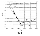
- the weighting coefficient h/pc decreased for all increasing skin temperatures in the ear and axilla temperature measurements, it has been found that, as illustrated in Figure 5 , the weighting coefficient reaches a minimum at near normal body temperature and then, due to the increasing value of h, increases.
- Empirical data suggests that the value h/pc decreases linearly 82 to a value of about.19 and a temperature of about 35.5 to 36.1°C (96-97°F). The coefficient then increases linearly with skin temperature but at a lesser slope at 84.
- the Exergen D501 Industrial Temperature Detector used in emissivity compensating cup and provided a peak temperature based on about ten temperature readings per second.
- that device did not perform a heat balance computation and was thus not suited to measurement of core temperature.
- the emissivity compensating cup was utilized in the axillary temperature detector with a heat balance computation, but that unit was not adapted to be scanned across the target surface. The detected peak in that device used to indicate when the reading had stabilized and could be relied upon.
- That peak detection was based on only one reading per second. Applicant's prior ear temperature detectors have obtained a peak temperature from ten readings per second but with pivoting of the detector rather than with lateral scan across the target surface. There was no emissivity compensating cup.
Abstract
Description
- In recent years, infrared thermometers have come into wide use for detection of temperature of adults. For core temperature readings, infrared thermometers which are adapted to be inserted into the patient's ear have been very successful. Early infrared thermometers were adapted to extend into the ear canal in order to view the tympanic membrane and provide an uncorrected, direct reading of tympanic temperature which correlates with pulmonary artery temperature. More recently, however, to provide for greater comfort and ease of use, ear thermometers have been designed to provide corrected readings of the generally cooler distal ear canal. Such thermometers measure temperature of distal ear canal tissue and calculate arterial core temperature via heat balance.
- Core temperature is a term used to describe deep body temperature and is approximated by oral, rectal, ear, pulmonary artery, esophageal and bladder temperatures and the like. Of those temperatures, pulmonary artery temperature is the most precise definition of core temperature since it is closest to the heart and its blood is supplied to all tissues. Calculations of arterial core temperature via heat balance provide approximations of the pulmonary artery temperature, and unless otherwise indicated, core temperature refers to the pulmonary artery temperature.
- The arterial heat balance approach is based on a model of heat flow through series thermal resistances from the arterial core temperature to the ear skin temperature and from the ear skin temperature to ambient temperature. Accordingly, after sensing both the skin temperature and ambient temperature, the arterial core temperature can be calculated. The thermal resistance model also allows for computation of equivalent oral and rectal temperatures with the mere adjustment of a weighting factor in the computation. Infrared ear thermometers using the arterial heat balance are disclosed in
U.S. Patents 4,993,419 ;5,012,813 ;5,199,436 ;5,381,796 ;5,445,158 ;5,653,238 and5,271,407 . - To avoid clinical difficulties in using ear thermometers, particularly with neonates, axillary (underarm) infrared thermometers have been introduced. Infrared thermometers designed for axillary temperature measurements are presented in
U.S. Patent Applications Serial Nos. 08/469,484 ,08/738,300 and08/881,891 . - In each of those devices, an infrared detector probe extends from a temperature display housing and may easily slide into the axilla to lightly touch the apex of the axilla and provide an accurate infrared temperature reading in as little as one-half second. The axillary thermometer also relies on the arterial heat balance approach to provide arterial, oral or rectal temperature.
- The axillary infrared thermometer has found great utility not only with neonates but as a screening tool in general, and especially for small children where conventional temperature measurements such as a thermometer under the tongue or a rectal thermometer are difficult.
- In ear and neonate axillary thermometry, the difference between skin temperature and ambient temperature has been weighted by a coefficient approximating h/pc, where h is an empirically determined coefficient which includes a radiation view factor between the skin tissue and ambient, p is perfusion rate and c is blood specific heat. In ear and neonate axillary thermometry, that coefficient was found empirically to be about .09 and .05, respectively, with only minor variations. However, with greater exposure for heat transfer and higher vasomotor functions, that coefficient has been determined empirically for the adult axillary region to be about .13 with much more significant variations according to the patent's temperature.
-
U.S. Patent 4,302,971 describes a method of detecting human body temperature by locating a temperature detector across a region of a forehead to measure a skin temperature over a superior orbital artery and computing a body temperature as a function of said measured temperature. - The problem solved by the present invention consists in increasing the detection accuracy.
- According to the present invention there is provided a method of detecting human body temperature according to
claim 1. - Embodiments of the present invention provide for particularly convenient temperature readings of neonate, child and adult temperatures by detecting the temperature of the forehead directly over the superficial temporal artery.
- Because arteries receive blood directly from the heart, they are a good choice for detecting core temperature, but an artery at the extremities of the body, such as those felt as pulse points at the wrist or ankle, are highly subject to vasoconstriction. This means, for example, that when an individual is extremely sick, in shock, or even just cold or nervous, the arteries constrict to reduce the flow of blood to that area as a means of retaining heat, or as in the case of shock, in an effort to redirect the blood to more critical areas of the body. This can result in a large temperature change at the artery which is a local artifact only and not representative of core temperature.
- Ruling out those arteries located in the extremities, in attempting to replicate the temperature at the source (the heart), we find, in the temporal artery, an artery as short a distance from the heart as possible, with a high and relatively constant blood flow, and that is readily accessible on all individuals. The heart, the lungs and the brain are vital to our very existence, so the supply of blood is high to these organs and continues as high as possible even through, in the face of grave illness, other areas may shut down to accommodate.
- Originating in the heart is the aorta, the main trunk of the arterial system. A direct extension of the aorta is the common carotid artery, a robust artery which runs upward in the neck and divides into the internal and external carotids. But, the carotids, even the external carotid, are at best partially embedded, and at worst completely embedded in the skull, and therefore are not accessible at the skin. Extending directly from the carotid is the temporal artery, again an artery dividing internally and externally. We look to the external branch which travels in front of the ear and up into the soft temple area, terminating in a fork directly between the skin and the skull adjoining the eyebrow.
- Demonstrably, the temporal artery is very easily accessible; in fact in most individuals, it is usually quite visible. Terminating in a two-prong fork, it easily doubles the assurance of measuring the correct area. Touching it does not present a risk of injury. There are no mucous membranes present, thus eliminating the risk of contaminates such as those found in the mouth and rectum. And, despite lying so close to the skin surface, the temporal artery perfusion, which is the flow of blood per unit volume of tissue, remains relatively constant and so ensures the stability of blood flow required for our measurement.
- In accordance with an embodiment of the method of the invention, a temperature sensor is scanned across the forehead over a temporal artery, and a peak temperature reading is provided from the scan. At least three readings per second should be made during the scan, preferably ten readings per second or more. The preferred radiation sensor is a radiation sensor which views a target surface of the forehead through a reflective cup. The cup has a large open diameter close to the target surface and a window at the base of the cup through which the radiation sensor views the target, the cup being out of the field of view of the sensor. The reflective cup is spaced from the target surface by a smooth lip of low thermal conductivity material.
- As in prior ear and axillary thermometers, internal core temperature can be computed from the function

- In accordance with another embodiment of the invention, electronics in the detector compute an internal temperature of the body as a function of ambient, temperature and sensed surface temperature. The function includes a weighted difference of surface temperature and ambient temperature, the weighting being varied with target temperature. In particular, the weighting is an approximation of h/pc at the forehead artery where h is a heat transfer coefficient between the target surface and ambient, p is perfusion rate and c is blood specific heat.
- The heat balance calculation is most accurate when the highest available temperature is detected, i.e., h/pc is minimum where perfusion p is highest, heat transfer coefficient h being approximately constant. Therefore, the detector must be able to discriminate the highest temperature which will be at one of the temporal artery branches.
- The foregoing and other objects, features and advantages of the invention will be apparent from the following more particular description of preferred embodiments of the invention, as illustrated in the accompanying drawings in which like reference characters refer to the same parts throughout the different views. The drawings are not necessarily to scale, emphasis instead being placed upon illustrating the principles of the invention.
-
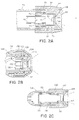
Figure 1 illustrates an infrared thermometer scanning the temporal artery in the forehead in accordance with the present invention. -
Figures 2A , B. and C are cross-sectional views of three embodiments of the radiation sensor assembly of the thermometer ofFigure 1 . -
Figure 3 is an electrical block diagram of the electronics of the thermometer ofFigure 1 . -
Figure 4 illustrates the arterial heat balance model. -
Figure 5 illustrates the change in weighting coefficient (1+h/pc) with change in skin temperature. - As illustrated in
Figure 1 , thetemporal arteries - In an embodiment of the method of the present invention, to locate the temporal artery, a temperature sensor, preferably a
radiation detector 20, is scanned across the side of the forehead over the temporal artery while electronics in the detector search for the peak reading which indicates the temporal artery. Preferably, that temperature reading is then further processed in accordance with an algorithm specific to the temporal artery for providing a display temperature which may, for example, correspond to core, oral or rectal temperature. - The
temperature detector 20 provides an audible beep with each peak reading. Adisplay 26 provides the temperature reading resulting from the electronic processing discussed below, updated to each new peak reading. Abutton 28 enables the user to activate the temperature detector. In one embodiment, anLED 22 which flashes with each peak reading can be observed when someone other than the patient performs the reading, and another LED on the other side of the housing can be observed by the patient, particularly when taking his own temperature. -
Figure 2A illustrates one sensor assembly for the radiation detector ofFigure 1 . The assembly is similar to that presented inU.S. Patent No. 6,056,435 . Athermopile 60 is mounted within acan 62 in conventional fashion. For high stability the thermopile may be a vapor deposited thermopile surrounded with xenon gas, but for reduced cost it may be a semiconductor thermopile surrounded with air. An infrared radiationtransparent window 63 is provided over a viewing opening in the can. Thecan 62 is set within a bore within aheat sink 64. A shoulder defines an aperture 66 at the base of a conical cup 68 through which the thermopile views the target. The cup is preferably of low emissivity in order to provide emissivity compensation as disclosed inU.S. Patent 4,636,091 . Preferably, theheat sink 64 in which the cup is formed is of aluminum. Alternatively, the heat sink may be of brass, nickel plated in the cup region. - An elastomeric o-
ring 70 is positioned behind thecan 62. Aplug 72 is threaded into the bore in theheat sink 64 to press thering 70 against the rear flange 71 of the can and thus press the flange against a shoulder in the heat sink bore. With the flange pressed against the shoulder and having a close tolerance with the larger diameter of the bore, anair gap 73 is maintained about the side and front of the can. This arrangement provides for good thermal contact between the can and theheat sink 64 at the rear and also makes the thermopile highly resistant to mechanical shock since the shock is only transferred through the thin flange past the shock absorbing elastomer. If the flange were rigidly clamped between metal parts, there would be a danger of shock breaking the gas seal of the can. Anopening 74 is provided through the center of theplug 72 for access ofelectrical leads 75 to the thermopile can. Theheat sink 64 is press fit in a plastic cap 77 which is threaded on to thetubular head 79 of the detector. - The plastic cap 77 in which the sensor assembly is mounted is of low thermal conductivity, preferably less than one hundredth that of aluminum. The housing thermally isolates the
heat sink 64 from the surrounding environment to minimize heat flow to the heat sink. Further, theheat sink 64 is of significant thermal mass. Accordingly, the RC time constant for change in temperature of the radiation sensor, with change in temperature to which the housing is exposed, can be made large for a more stable temperature reading. The thermal resistance is made high by the low conductivity housing, and the thermal capacitance is made high by the large mass of theheat sink 64. That RC time constant should be at least 5 minutes and is preferably about 25 minutes. - Past designs of infrared thermometers, such as presented in
U.S. Patent 4,993,419 , have relied on a massive thermopile can which also served as the heat sink. That design assured a high RC time constant for thermal conduction through the external thermal barrier to the heat sink relative to a thermal RC time constant for temperature response of the cold junction to heat transferred to the heat sink. The latter low RC time constant was obtained by assuring a low thermal resistance to the cold junction using expensive high conductivity material in a specially designed can/heat sink. In the present device, a design goal is to use a conventional low cost thermopile mounted in a light weight can which does not provide the low thermal resistance of the prior design. Accordingly, it is important that the can be mounted to assure that all heat conduction to the thermopile be through the rear of the can which serves as the thermal ground to the thermopile. That objective is obtained by making thermal contact to the can through the rear flange and assuring an air space about the sides and front of the can. - Forming the emissivity compensating cup 68 in the heat sink reduces the cost of the assembly and also improves the thermal characteristics. Although the emissivity of the cup is ideally zero, it is in fact about. 1. With the cup formed as part of the heat sink, it is at the temperature to which the can is grounded. Accordingly, any thermal emissions from the surface 68 will be at substantially the same temperature as the cold junction and thus not be seen. The electronics can also be calibrated to compensate for the loss of reflectance due to non-ideal emissivity, but that calibration is affected by the temperature of the reflective surface. By assuring that the surface 68 is at the temperature to which the thermopile can is grounded, the temperature of the surface is generally known and compensation can be made temperature dependent.
- When adapted to household use, concerns for patient cross-contamination associated with clinical temperature detectors is not so significant. Further, at the forehead, evaporation of moisture is not as significant as in the ear and axillary applications. Accordingly, the disposable radiation transparent covers used in prior infrared thermometers, such as in
U.S. Patent Nos. 5,893,833 and5.874,736 is less desirable. However, in the clinical environment, the transparent cover is still preferred to prevent cross contamination. - During the scanning of the radiation detector across the forehead, contact of the housing 78 with the skin can cause cooling of the skin. To minimize that cooling, a
circular lip 81 protrudes axially beyond the tip of theheat sink 64. The lip has a thin radius of 0.508 to 1.27 mm (.02 to .05 inch), preferably about 0.762 mm (.03 inch), to minimize the thermal conductance through the insulation material. Theheat sink 64 is recessed 0.508 to 1.27 mm (.02 to .05 inch), preferably about 0.762 mm (.03 inch) behind the tip of the lip. For comfort during scanning, the lip has a smooth curve. - Another embodiment of the radiation sensor assembly is presented in
Figure 2B . As in the prior embodiment, the thermopile 120 is positioned within acan 122. The can is retained in aheat sink 124 by an o-ring 126 which presses against theflange 128 of the can and is set within a circumferential groove in thebore 130 of the heat sink. As before,wires 132 extend through that bore. Thehousing 134 of the detector head is a split tube formed of two parts which meet along longitudinal seams. The two tube parts are held together by anut 136 to which aplastic cap 138 is snap fit. The heat sink is retained in the assembly by an o-ring 140 which is seated within a groove in the heat sink and a groove in thenut 136. As before, thecap 138 has a curved lip which extends beyond the tip of theheat sink 124.Cap 138 is of soft material for the comfort of the patient. - In the embodiment of
Figure 2C , the thermopile is positioned within a can 150 of high thermal mass similar to that disclosed inU.S. Patent 5,012,813 . The can is set within asleeve 152 which is retained in thehead housing 154 by o-rings plastic cap 160 is threaded onto thehead 154, and thecan 150 is centered within the cap by an additional o-ring 162. Alow emissivity cup 164 is press fit within thecap 160 and, as before, is recessed behind asmooth lip 166. - An electrical block diagram for the radiation detector is presented in
Figure 3 . Amicroprocessor 80 is at the heart of the circuit. Apower control circuit 82 responds to activation of thebutton switch 84 by the user to apply power to the microprocessor and other elements of the circuit. That power is maintained until the microprocessor completes the measurement cycle and signals thepower control 82 to power down. The microprocessor is clocked by anoscillator circuit 86 and may communicate with an external source for programming and calibration throughcommunication conductors 88. The temperature determined by the microprocessor is displayed on theliquid crystal display 100, and detection of peaks during the temperature processing is indicated by abeeper 102. Peaks are detected from readings taken at least three times per second, and preferably about ten times per second, for rapid scan across the forehead to avoid cooling of the forehead through the detector. During the measurement process, the microprocessor takes readings through a multiplexer/analog-to-digital converter 90. Thepreferred microprocessor 80 is a PIC16C74 which includes an internal 8-bit A-D converter. To minimize expense, the circuit is designed to rely solely on that A-D converter. -
Thermopile 92 provides a voltage output signal equal to the fourth power difference between target temperature and the temperature of the thermopile cold junction, offset byvoltage reference 94. The voltage output from the thermopile is amplified by anamplifier 96, having a gain in the order of 1000, which also provides an offset determined by a pulse width modulatedfilter 108 controlled by the microprocessor. Through operation of the multiplexer, the microprocessor provides an analog-to-digital conversion of the amplified sensor output and of the detector temperature Td provided bytemperature sensor 98. Thetemperature sensor 98 is positioned to sense the substantially uniform temperature of the thermopile cold junction, can and heat sink. An auto zeroswitch 104 is included to allow for isolation of theamplifier 96 from thethermopile 92 during a calibration sequence as discussed in prior U.S. applicationU.S. Patent No. 5,874.736 . - It is well known that the output of the thermopile is proportional to (

sensor 98. From that relationship, Ts can be computed. It is also known that, based on the determined skin temperature and the ambient temperature to which the skin is exposed, an internal core temperature can be computed using the arterial heat balance approach illustrated inFigure 4 . Heat flux q from the internal core temperature Tc passes through theskin 30 to the ambient environment at temperature Tz. The skin is thus held at some intermediate temperature Ts. - The heat loss of skin, such as at the forehead, the external ear canal or axilla, to the environment can be calculated with the following well-known equation:

- Heat flow from the core arterial source to the skin is via blood circulation, which is many times more effective than tissue conduction. Thermal transport via the circulation can be described with the following equation:

and Ts are core and skin temperatures, respectively. - Accordingly, the skin can be viewed thermally as tissue being warmed by its blood supply as governed by equation 3, balanced by radiating heat to ambient as governed by equation 2.
- Equating:


- Equation 5 then provides a method to calculate core temperature Tc when skin temperature Ts and ambient temperature Ta are known, and the coefficients (or their ratio) have been empirically determined.
- Solving for Tc:

- An alternative method of calculating is to employ an electrical analog technique, since equations 2 and 3 have the identical form of a simple voltage/current relationship. The method employs the convention that electrical current is analogous to heat flow and voltage differential is analogous to temperature differential.
- Accordingly, equations 2 and 3 may be written as:


Figure 4 ). A third equation with a more convenient form can be written as:


- The k Factor can be rewritten as follows:

- In the weighting coefficient, c is a constant. In ear temperature and neonatal axillary temperature measurements, the perfusion rate is also generally constant, resulting in h/pc of about .09 for adult ears and .05 for neonates. For a normal adult, the perfusion rate of the axilla is such that the weighting coefficient h/pc is about 13. Further, the perfusion rate varies according to the condition of the patient. In particular, with a fever, the perfusion rate can become much higher. Similarly, in the forehead, perfusion rate varies with skin temperature.
- In both the ear and axilla, the coefficient h is relatively constant. The forehead has greater exposure to the ambient environment, and the radiation heat loss increases with increased skin temperature. Thus, where the weighting coefficient h/pc decreased for all increasing skin temperatures in the ear and axilla temperature measurements, it has been found that, as illustrated in
Figure 5 , the weighting coefficient reaches a minimum at near normal body temperature and then, due to the increasing value of h, increases. Empirical data suggests that the value h/pc decreases linearly 82 to a value of about.19 and a temperature of about 35.5 to 36.1°C (96-97°F). The coefficient then increases linearly with skin temperature but at a lesser slope at 84. The linear approximations illustrated inFigure 5 are used in the computations in the clinical model. However, in the consumer model, those linear approximations are replaced by a single polynomial approximation 86:

- Individual, aspects of the radiation detector which make it particularly suited to providing temperature readings from the temporal artery can be found in applicant's prior designs. However, none of those designs provide the unique combination of elements which enable consistent measurements of core temperature by scanning across a temporal artery. Specifically, the Exergen D501 Industrial Temperature Detector used in emissivity compensating cup and provided a peak temperature based on about ten temperature readings per second. However, that device did not perform a heat balance computation and was thus not suited to measurement of core temperature. The emissivity compensating cup was utilized in the axillary temperature detector with a heat balance computation, but that unit was not adapted to be scanned across the target surface. The detected peak in that device used to indicate when the reading had stabilized and could be relied upon. That peak detection was based on only one reading per second. Applicant's prior ear temperature detectors have obtained a peak temperature from ten readings per second but with pivoting of the detector rather than with lateral scan across the target surface. There was no emissivity compensating cup.
- While this invention has been particularly shown and described with references to preferred embodiments thereof, it will be understood by those skilled in the art that various changes in form and details may be made therein without departing from the scope of the invention encompassed by the appended claims.
Claims (9)
- A method of detecting human body temperature by scanning a temperature detector across a region of a forehead to measure a peak temperature reading of skin over a temporal artery and computing a body temperature as a function of the peak temperature based on a model of heat balance.
- A method as claimed in claim 1 wherein temporal artery temperature is measured with an infrared detector.
- A method as claimed in any of claims 1 to 2, further comprising computing an internal temperature of the body as a function of ambient temperature and sensed surface temperature.
- A method as claimed in claim 3 wherein the function includes a weighting by an approximation of h/pc at a forehead artery where h is a heat transfer coefficient between the target surface and ambient, p is perfusion rate and c is blood specific heat.
- A method as claimed in Claim 1 comprising measuring peak temperature from at least three readings per second during scan of a temperature detector across the temporal artery and processing the detected peak temperature to provide a temperature display based on a model of heat balance relative to the detected temporal artery temperature.
- A method according to any foregoing claim wherein the method employs a body temperature detector comprising:a radiation sensor (92); andelectronics (80) for measuring peak temperature;wherein the electronics measure peak temperature from at least three readings per second during scan of the radiation sensor across the temporal artery and the electronics process the detected peak temperature to provide a temperature display based on a model of heat balance relative to a detected arterial temperature; and the detector further comprises a reflective cup (68) having a window at the base of the cup through which the radiation sensor views the target surface area.
- A method as claimed in claim 6, wherein the detector further comprises a smooth lip (81) of low thermal conductivity material about the reflective cup, the reflective cup (68) being spaced from the target surface area by the smooth lip (81) during measuring of the temperature.
- A method as claimed in claim 6 or claim 7, wherein the electronics compute an internal temperature of the body as a function of ambient temperature and measured peak temperature.
- A method as claimed in claim 8 wherein the function includes a weighting by an approximation of h/pc at a forehead temporal artery where h is a heat transfer coefficient between the target surface and ambient, p is perfusion rate and c is blood specific heat.
Priority Applications (1)
| Application Number | Priority Date | Filing Date | Title |
|---|---|---|---|
| EP10180393A EP2317292A3 (en) | 1998-09-11 | 1999-09-10 | Temporal artery temperature detector |
Applications Claiming Priority (3)
| Application Number | Priority Date | Filing Date | Title |
|---|---|---|---|
| US151482 | 1998-09-11 | ||
| US09/151,482 US6292685B1 (en) | 1998-09-11 | 1998-09-11 | Temporal artery temperature detector |
| PCT/US1999/020855 WO2000016051A1 (en) | 1998-09-11 | 1999-09-10 | Temporal artery temperature detector |
Related Child Applications (1)
| Application Number | Title | Priority Date | Filing Date |
|---|---|---|---|
| EP10180393.0 Division-Into | 2010-09-27 |
Publications (2)
| Publication Number | Publication Date |
|---|---|
| EP1114302A1 EP1114302A1 (en) | 2001-07-11 |
| EP1114302B1 true EP1114302B1 (en) | 2012-02-01 |
Family
ID=22538964
Family Applications (2)
| Application Number | Title | Priority Date | Filing Date |
|---|---|---|---|
| EP10180393A Withdrawn EP2317292A3 (en) | 1998-09-11 | 1999-09-10 | Temporal artery temperature detector |
| EP99945647A Expired - Lifetime EP1114302B1 (en) | 1998-09-11 | 1999-09-10 | Temporal artery temperature detection |
Family Applications Before (1)
| Application Number | Title | Priority Date | Filing Date |
|---|---|---|---|
| EP10180393A Withdrawn EP2317292A3 (en) | 1998-09-11 | 1999-09-10 | Temporal artery temperature detector |
Country Status (6)
| Country | Link |
|---|---|
| US (6) | US6292685B1 (en) |
| EP (2) | EP2317292A3 (en) |
| JP (1) | JP4481496B2 (en) |
| AT (1) | ATE544058T1 (en) |
| AU (1) | AU5821299A (en) |
| WO (1) | WO2000016051A1 (en) |
Cited By (1)
| Publication number | Priority date | Publication date | Assignee | Title |
|---|---|---|---|---|
| US9194749B2 (en) | 1998-09-11 | 2015-11-24 | Exergen Corporation | Temporal artery temperature detector |
Families Citing this family (163)
| Publication number | Priority date | Publication date | Assignee | Title |
|---|---|---|---|---|
| US6056435A (en) * | 1997-06-24 | 2000-05-02 | Exergen Corporation | Ambient and perfusion normalized temperature detector |
| IL126224A0 (en) * | 1998-09-15 | 1999-05-09 | Gerlitz Jonathan | Ear thermometer and detector therefor |
| DE69929710T2 (en) * | 1998-12-15 | 2006-09-21 | Citizen Watch Co., Ltd. | CLINICAL RADIATION THERMOMETER |
| EP1185845A1 (en) * | 1999-06-23 | 2002-03-13 | Eliahu Rubenstein | Fever alarm system |
| DE19929503B4 (en) * | 1999-06-28 | 2008-06-26 | Braun Gmbh | IR thermometers for different measuring locations |
| US6319206B1 (en) * | 1999-11-24 | 2001-11-20 | Exergen Corporation | Temporal thermometer disposable cap |
| IT1317648B1 (en) * | 2000-05-19 | 2003-07-15 | Tecnica S R L | PERFECTED INFRARED THERMOMETER |
| WO2001096825A1 (en) * | 2000-06-13 | 2001-12-20 | Omron Corporation | Pyrometer |
| US6773405B2 (en) * | 2000-09-15 | 2004-08-10 | Jacob Fraden | Ear temperature monitor and method of temperature measurement |
| WO2002061858A2 (en) | 2000-11-17 | 2002-08-08 | Thermogenic Imaging, Inc. | Apparatus and methods for infrared calorimetric measurements |
| US20020132360A1 (en) | 2000-11-17 | 2002-09-19 | Flir Systems Boston, Inc. | Apparatus and methods for infrared calorimetric measurements |
| EP1249691A1 (en) * | 2001-04-11 | 2002-10-16 | Omron Corporation | Electronic clinical thermometer |
| JP3900865B2 (en) * | 2001-06-04 | 2007-04-04 | オムロンヘルスケア株式会社 | Infrared thermometer, infrared thermometer temperature state estimation method, information notification method, and measurement operation management method |
| US7017433B2 (en) * | 2001-10-04 | 2006-03-28 | Ssi Technologies, Inc. | Non-contacting sensor multichip module with integral heat-sinks |
| US8328420B2 (en) | 2003-04-22 | 2012-12-11 | Marcio Marc Abreu | Apparatus and method for measuring biologic parameters |
| US10123732B2 (en) | 2002-04-22 | 2018-11-13 | Geelux Holdings, Ltd. | Apparatus and method for measuring biologic parameters |
| JP4347216B2 (en) | 2002-04-22 | 2009-10-21 | マルシオ マルク アブリュー | Biological parameter measuring device |
| US8849379B2 (en) * | 2002-04-22 | 2014-09-30 | Geelux Holdings, Ltd. | Apparatus and method for measuring biologic parameters |
| US6971790B2 (en) * | 2002-10-11 | 2005-12-06 | Welch Allyn, Inc. | Thermometry probe calibration method |
| US20040095985A1 (en) * | 2002-11-15 | 2004-05-20 | Ko Kun Yuan | Dual-use infrared thermometer |
| WO2004055488A1 (en) * | 2002-12-12 | 2004-07-01 | Sherwood Services Ag | Thermal tympanic thermometer tip |
| AU2007200873B2 (en) * | 2002-12-12 | 2008-04-03 | Cardinal Health 529, Llc | Thermal tympanic thermometer tip |
| US7434991B2 (en) * | 2002-12-12 | 2008-10-14 | Covidien Ag | Thermal tympanic thermometer |
| WO2004074794A1 (en) * | 2003-02-20 | 2004-09-02 | Ysi Incorporated | Digitally modified resistive output for a temperature sensor |
| CN105380608A (en) * | 2003-02-26 | 2016-03-09 | 马尔西奥·马克·奥雷利奥·马丁斯·阿布雷乌 | Apparatus and method for measuring biologic parameters |
| JP4558719B2 (en) * | 2003-02-26 | 2010-10-06 | アブリュー・マルシオ・マルク・オウレリオ・マーチン | Detector, climate control device and radiation detector |
| AU2012247045B2 (en) * | 2003-02-26 | 2014-05-22 | Marcio Marc Aurelio Martins Abreu | Apparatus and method for measuring biologic parameters |
| AU2014215951B2 (en) * | 2003-02-26 | 2015-11-19 | Abreu, Marcio Marc Aurelio Martins MR | Apparatus and method for measuring biologic parameters |
| US8465151B2 (en) | 2003-04-15 | 2013-06-18 | Ipventure, Inc. | Eyewear with multi-part temple for supporting one or more electrical components |
| US7922321B2 (en) * | 2003-10-09 | 2011-04-12 | Ipventure, Inc. | Eyewear supporting after-market electrical components |
| US7500746B1 (en) | 2004-04-15 | 2009-03-10 | Ip Venture, Inc. | Eyewear with radiation detection system |
| US7255437B2 (en) * | 2003-10-09 | 2007-08-14 | Howell Thomas A | Eyeglasses with activity monitoring |
| US7806525B2 (en) | 2003-10-09 | 2010-10-05 | Ipventure, Inc. | Eyeglasses having a camera |
| US8109629B2 (en) * | 2003-10-09 | 2012-02-07 | Ipventure, Inc. | Eyewear supporting electrical components and apparatus therefor |
| KR20060012649A (en) * | 2003-05-27 | 2006-02-08 | 카디오웨이브, 인코포레이티드. | Methods and apparatus for a remote, noninvasive technique to detect core body temperature in a subject via thermal imaging |
| US7785266B2 (en) | 2003-08-19 | 2010-08-31 | Advanced Monitors Corporation | Medical thermometer for determining body core temperature |
| US7938783B2 (en) | 2003-08-19 | 2011-05-10 | Advanced Monitors Corporation | Medical body core thermometer |
| US20130281897A1 (en) * | 2003-09-04 | 2013-10-24 | Ahof Biophysical Systems Inc. | Non-invasive reperfusion system by deformation of remote, superficial arteries at a frequency much greater than the pulse rate |
| US7438410B1 (en) | 2003-10-09 | 2008-10-21 | Ip Venture, Inc. | Tethered electrical components for eyeglasses |
| US10345625B2 (en) | 2003-10-09 | 2019-07-09 | Ingeniospec, Llc | Eyewear with touch-sensitive input surface |
| US11513371B2 (en) | 2003-10-09 | 2022-11-29 | Ingeniospec, Llc | Eyewear with printed circuit board supporting messages |
| US10310296B2 (en) | 2003-10-09 | 2019-06-04 | Ingeniospec, Llc | Eyewear with printed circuit board |
| US11630331B2 (en) | 2003-10-09 | 2023-04-18 | Ingeniospec, Llc | Eyewear with touch-sensitive input surface |
| EP1530034A1 (en) * | 2003-11-05 | 2005-05-11 | Microlife Intellectual Property GmbH | An infrared thermometer and a method for determining a temperature |
| TWM251738U (en) * | 2004-01-30 | 2004-12-01 | Yuan Ho Harmony Co Ltd | Infrared temperature sensor |
| EP1568975A1 (en) * | 2004-02-26 | 2005-08-31 | Microlife Intellectual Property GmbH | A probe assembly for an infrared medical thermometer and an infrared medical thermometer |
| US10227063B2 (en) | 2004-02-26 | 2019-03-12 | Geelux Holdings, Ltd. | Method and apparatus for biological evaluation |
| EP1804653A4 (en) * | 2004-05-20 | 2009-08-19 | Medisim Ltd | Temperature measurement device |
| DE102004028359B4 (en) * | 2004-06-11 | 2007-09-13 | Drägerwerk AG | Device for measuring body core temperature |
| US11644693B2 (en) | 2004-07-28 | 2023-05-09 | Ingeniospec, Llc | Wearable audio system supporting enhanced hearing support |
| US8337013B2 (en) | 2004-07-28 | 2012-12-25 | Ipventure, Inc. | Eyeglasses with RFID tags or with a strap |
| US11829518B1 (en) | 2004-07-28 | 2023-11-28 | Ingeniospec, Llc | Head-worn device with connection region |
| US11852901B2 (en) | 2004-10-12 | 2023-12-26 | Ingeniospec, Llc | Wireless headset supporting messages and hearing enhancement |
| US20060122473A1 (en) * | 2004-10-13 | 2006-06-08 | Kill Robert A | Wireless patch temperature sensor system |
| US7083330B1 (en) * | 2004-10-19 | 2006-08-01 | Huang Hua Co., Ltd. | Ear thermometer having breakable ear cap |
| US7815367B2 (en) * | 2004-11-16 | 2010-10-19 | Welch Allyn, Inc. | Multi-site infrared thermometer |
| US7857507B2 (en) * | 2004-11-16 | 2010-12-28 | Welch Allyn, Inc. | Temperature patch and method of using the same |
| ITMI20050772A1 (en) * | 2005-04-29 | 2006-10-30 | Tecnimed Srl | EQUIPMENT FOR TEMPERATURE MEASUREMENT IN PARTICULAR OF A PATIENT |
| DE102005037921B3 (en) * | 2005-08-11 | 2006-06-14 | Dräger Medical AG & Co. KG | Temperature measuring device, for patient use, has evaluating means for detecting skin surface temperature from first temperature measured value and determines temperature at skin surface where double temperature sensor is in contact |
| US11733549B2 (en) | 2005-10-11 | 2023-08-22 | Ingeniospec, Llc | Eyewear having removable temples that support electrical components |
| KR101370985B1 (en) | 2005-10-24 | 2014-03-10 | 마시오 마크 아우렐리오 마틴스 애브리우 | Apparatus and method for measuring biologic parameters |
| US7275867B2 (en) * | 2005-12-01 | 2007-10-02 | Oriental System Technology Inc. | Probe assembly of infrared thermometer |
| CA2538940A1 (en) * | 2006-03-03 | 2006-06-22 | James W. Haslett | Bandage with sensors |
| TWI274857B (en) * | 2006-03-03 | 2007-03-01 | Radiant Innovation | Structural improvement of a probe |
| US7597668B2 (en) * | 2006-05-31 | 2009-10-06 | Medisim Ltd. | Non-invasive temperature measurement |
| US7988352B2 (en) * | 2006-11-01 | 2011-08-02 | Radiant Innovation Inc. | Probe structure |
| WO2008110949A1 (en) | 2007-03-15 | 2008-09-18 | Koninklijke Philips Electronics N.V. | Methods and devices for measuring core body temperature |
| US8308353B2 (en) * | 2007-03-26 | 2012-11-13 | Terumo Kabushiki Kaisha | Ear thermometer and method of manufacturing ear thermometer |
| US20080239920A1 (en) * | 2007-03-27 | 2008-10-02 | Francesco Pompei | Wireless transmission of temperature data |
| US8160836B2 (en) * | 2007-04-17 | 2012-04-17 | Exergen Corporation | Wireless transmission of temperature data for a geographic area |
| US8167813B2 (en) * | 2007-05-17 | 2012-05-01 | Immersion Medical, Inc. | Systems and methods for locating a blood vessel |
| TW200909790A (en) * | 2007-08-21 | 2009-03-01 | Radiant Innovation Inc | Method of detecting living-body body temperature |
| US20130096437A1 (en) * | 2007-08-21 | 2013-04-18 | Radiant Innovation Inc. | Method for detecting temple hot spot temperature of a live body |
| US20100036269A1 (en) * | 2008-08-07 | 2010-02-11 | Searete Llc, A Limited Liability Corporation Of The State Of Delaware | Circulatory monitoring systems and methods |
| US20090287120A1 (en) | 2007-12-18 | 2009-11-19 | Searete Llc, A Limited Liability Corporation Of The State Of Delaware | Circulatory monitoring systems and methods |
| US8636670B2 (en) | 2008-05-13 | 2014-01-28 | The Invention Science Fund I, Llc | Circulatory monitoring systems and methods |
| US9672471B2 (en) | 2007-12-18 | 2017-06-06 | Gearbox Llc | Systems, devices, and methods for detecting occlusions in a biological subject including spectral learning |
| US9717896B2 (en) | 2007-12-18 | 2017-08-01 | Gearbox, Llc | Treatment indications informed by a priori implant information |
| US20090204008A1 (en) * | 2008-02-08 | 2009-08-13 | Daniel Beilin | Whole body infrared thermography systems and methods |
| US8185341B2 (en) * | 2008-05-30 | 2012-05-22 | Medisim Ltd. | Surface temperature profile |
| US7942825B2 (en) * | 2008-06-09 | 2011-05-17 | Kimberly-Clark Worldwide Inc. | Method and device for monitoring thermal stress |
| JP5308844B2 (en) * | 2009-01-28 | 2013-10-09 | 株式会社ミクニ | Infrared temperature measuring device |
| EP2419004B1 (en) * | 2009-04-15 | 2017-07-19 | 3M Innovative Properties Company | Deep tissue temperature probe constructions |
| EP2942003A3 (en) | 2009-04-15 | 2016-03-23 | 3M Innovative Properties Company of 3M Center | Deep tissue temperature probe constructions |
| EP2278289A1 (en) | 2009-07-22 | 2011-01-26 | Medisim Ltd. | Thermometric apparatus and a method for thermometric measurement |
| US8226294B2 (en) * | 2009-08-31 | 2012-07-24 | Arizant Healthcare Inc. | Flexible deep tissue temperature measurement devices |
| US8226573B2 (en) * | 2009-11-16 | 2012-07-24 | Tyco Healthcare Group Lp | Thermometer probe |
| US8325048B2 (en) * | 2009-12-08 | 2012-12-04 | Kimberly-Clark Worldwide, Inc. | Thermal stress indicator |
| US20110194585A1 (en) * | 2010-02-09 | 2011-08-11 | Abhishek Shrivastava | Multiple object non-contact thermometer |
| US8301408B2 (en) * | 2010-03-09 | 2012-10-30 | Invensys Systems, Inc. | Temperature prediction transmitter |
| US8292502B2 (en) | 2010-04-07 | 2012-10-23 | Arizant Healthcare Inc. | Constructions for zero-heat-flux, deep tissue temperature measurement devices |
| US8292495B2 (en) | 2010-04-07 | 2012-10-23 | Arizant Healthcare Inc. | Zero-heat-flux, deep tissue temperature measurement devices with thermal sensor calibration |
| WO2011150404A2 (en) | 2010-05-27 | 2011-12-01 | Exergen Corporation | Method and apparatus for accurate detection of fever |
| TW201210569A (en) * | 2010-09-07 | 2012-03-16 | Radiant Innovation Inc | Infrared body temperature measuring device having communication function |
| US8714816B2 (en) | 2010-09-12 | 2014-05-06 | Medisim Ltd. | Temperature sensor with calibrated analog resistive output |
| US20120083710A1 (en) | 2010-09-30 | 2012-04-05 | Medism Ltd. | Ergonomic hand-held thermometer |
| WO2012067282A1 (en) | 2010-11-17 | 2012-05-24 | (주)이지템 | Mobile device and method for measuring temperature of thermal picture including body temperature |
| US8657758B2 (en) | 2010-12-02 | 2014-02-25 | Welch Allyn, Inc. | Devices and methods for temperature determination |
| US9354122B2 (en) | 2011-05-10 | 2016-05-31 | 3M Innovative Properties Company | Zero-heat-flux, deep tissue temperature measurement system |
| US8593251B2 (en) | 2011-06-16 | 2013-11-26 | Alan Camerik Heller | Systems for detecting a febrile condition and reducing risks of spreading infection |
| US9405135B2 (en) | 2011-09-15 | 2016-08-02 | Ipventure, Inc. | Shutter eyewear |
| US10624790B2 (en) | 2011-09-15 | 2020-04-21 | Ipventure, Inc. | Electronic eyewear therapy |
| US20130116591A1 (en) * | 2011-11-04 | 2013-05-09 | Alan C. Heller | Systems and devices for real time health status credentialing |
| US9320642B1 (en) * | 2012-06-04 | 2016-04-26 | The Surgical Company International B.V. | Method of and system for selecting patient temperature regulation tools |
| US8452382B1 (en) * | 2012-09-21 | 2013-05-28 | Brooklands Inc. | Non-contact thermometer sensing a carotid artery |
| WO2014070045A1 (en) * | 2012-10-30 | 2014-05-08 | Zakrytoe Aktsionernoe Obshchestvo "Cem Tehnolodzhi" | The method and the device for monitoring of diseases |
| US10042186B2 (en) | 2013-03-15 | 2018-08-07 | Ipventure, Inc. | Electronic eyewear and display |
| US20150057561A1 (en) * | 2013-08-26 | 2015-02-26 | Benny Tal | System, method and computer readable medium for determining a core temperature of a person |
| CA2980036A1 (en) | 2013-10-11 | 2015-04-16 | Marcio Marc Abreu | Method and apparatus for biological evaluation |
| US9939334B2 (en) | 2013-12-05 | 2018-04-10 | Medisim, Ltd. | Fast responsive personalized thermometer |
| US9572647B2 (en) | 2013-12-31 | 2017-02-21 | i4c Innovations Inc. | Paired thermometer temperature determination |
| CA2936235A1 (en) | 2014-01-10 | 2015-07-16 | Marcio Marc Abreu | Devices to monitor and provide treatment at an abreu brain tunnel |
| AU2015204638A1 (en) * | 2014-01-10 | 2016-07-21 | Marcio Marc Abreu | Device for measuring the infrared output of the Abreu brain thermal tunnel |
| CN106163463A (en) | 2014-01-22 | 2016-11-23 | 马尔西奥·马克·阿布雷乌 | It is configured to the device processed in ABREU brain fever passage offer |
| US9599521B2 (en) | 2014-01-27 | 2017-03-21 | Medisim, Ltd. | Interface between vital-signs sensors and patient monitor |
| US9538729B2 (en) | 2014-04-08 | 2017-01-10 | Medisim, Ltd. | Cattle monitoring for illness |
| GB2528044B (en) | 2014-07-04 | 2018-08-22 | Arc Devices Ni Ltd | Non-touch optical detection of vital signs |
| US8965090B1 (en) | 2014-07-06 | 2015-02-24 | ARC Devices, Ltd | Non-touch optical detection of vital signs |
| US9854973B2 (en) | 2014-10-25 | 2018-01-02 | ARC Devices, Ltd | Hand-held medical-data capture-device interoperation with electronic medical record systems |
| AU2016228998A1 (en) | 2015-03-10 | 2017-09-28 | Marcio Marc Abreu | Devices, apparatuses, systems, and methods for measuring temperature of an ABTT terminus |
| US10383573B2 (en) | 2015-03-31 | 2019-08-20 | Geelux Holdings, Ltd. | Apparatus configured to support a device on a head |
| CN104958062B (en) * | 2015-05-04 | 2018-06-08 | 中国人民解放军第三军医大学第一附属医院 | Array infrared thermography and its application in Early Identification Ischemic Stroke and hemorrhagic apoplexy |
| US9968264B2 (en) | 2015-06-14 | 2018-05-15 | Facense Ltd. | Detecting physiological responses based on thermal asymmetry of the face |
| US10159411B2 (en) | 2015-06-14 | 2018-12-25 | Facense Ltd. | Detecting irregular physiological responses during exposure to sensitive data |
| US10136856B2 (en) | 2016-06-27 | 2018-11-27 | Facense Ltd. | Wearable respiration measurements system |
| US10523852B2 (en) | 2015-06-14 | 2019-12-31 | Facense Ltd. | Wearable inward-facing camera utilizing the Scheimpflug principle |
| US10130308B2 (en) | 2015-06-14 | 2018-11-20 | Facense Ltd. | Calculating respiratory parameters from thermal measurements |
| US10299717B2 (en) | 2015-06-14 | 2019-05-28 | Facense Ltd. | Detecting stress based on thermal measurements of the face |
| US10080861B2 (en) | 2015-06-14 | 2018-09-25 | Facense Ltd. | Breathing biofeedback eyeglasses |
| US10064559B2 (en) | 2015-06-14 | 2018-09-04 | Facense Ltd. | Identification of the dominant nostril using thermal measurements |
| US10113913B2 (en) | 2015-10-03 | 2018-10-30 | Facense Ltd. | Systems for collecting thermal measurements of the face |
| US10151636B2 (en) | 2015-06-14 | 2018-12-11 | Facense Ltd. | Eyeglasses having inward-facing and outward-facing thermal cameras |
| US10045737B2 (en) | 2015-06-14 | 2018-08-14 | Facense Ltd. | Clip-on device with inward-facing cameras |
| US10216981B2 (en) | 2015-06-14 | 2019-02-26 | Facense Ltd. | Eyeglasses that measure facial skin color changes |
| US10130299B2 (en) | 2015-06-14 | 2018-11-20 | Facense Ltd. | Neurofeedback eyeglasses |
| US10085685B2 (en) | 2015-06-14 | 2018-10-02 | Facense Ltd. | Selecting triggers of an allergic reaction based on nasal temperatures |
| US10045699B2 (en) | 2015-06-14 | 2018-08-14 | Facense Ltd. | Determining a state of a user based on thermal measurements of the forehead |
| US10165949B2 (en) | 2015-06-14 | 2019-01-01 | Facense Ltd. | Estimating posture using head-mounted cameras |
| US10136852B2 (en) | 2015-06-14 | 2018-11-27 | Facense Ltd. | Detecting an allergic reaction from nasal temperatures |
| US10154810B2 (en) | 2015-06-14 | 2018-12-18 | Facense Ltd. | Security system that detects atypical behavior |
| US10076270B2 (en) | 2015-06-14 | 2018-09-18 | Facense Ltd. | Detecting physiological responses while accounting for touching the face |
| US10045726B2 (en) | 2015-06-14 | 2018-08-14 | Facense Ltd. | Selecting a stressor based on thermal measurements of the face |
| US10130261B2 (en) | 2015-06-14 | 2018-11-20 | Facense Ltd. | Detecting physiological responses while taking into account consumption of confounding substances |
| US10092232B2 (en) | 2015-06-14 | 2018-10-09 | Facense Ltd. | User state selection based on the shape of the exhale stream |
| US10076250B2 (en) | 2015-06-14 | 2018-09-18 | Facense Ltd. | Detecting physiological responses based on multispectral data from head-mounted cameras |
| US10045511B1 (en) | 2015-08-20 | 2018-08-14 | Medisim, Ltd. | Cattle and other veterinary monitoring |
| CN105125178A (en) * | 2015-08-28 | 2015-12-09 | 中粮饲料有限公司 | Pig body temperature monitoring method and device |
| USD793255S1 (en) | 2015-11-06 | 2017-08-01 | Withings | Thermometer |
| US11874173B1 (en) | 2015-11-24 | 2024-01-16 | Exergen Corporation | Devices and methods for detecting inflammation |
| US10390692B2 (en) | 2015-11-25 | 2019-08-27 | Htc Corporation | Hybrid detection apparatus |
| US10184844B2 (en) | 2015-12-31 | 2019-01-22 | Withings | Compact home thermometer |
| FR3059824B1 (en) | 2016-12-07 | 2019-06-21 | Ulis | INFRARED IMAGE SENSOR |
| US10506926B2 (en) | 2017-02-18 | 2019-12-17 | Arc Devices Limited | Multi-vital sign detector in an electronic medical records system |
| US10492684B2 (en) | 2017-02-21 | 2019-12-03 | Arc Devices Limited | Multi-vital-sign smartphone system in an electronic medical records system |
| EP3618699A4 (en) * | 2017-05-05 | 2021-02-24 | Trividia Health, Inc. | Methods and systems for hematocrit measurement |
| JP6999301B2 (en) * | 2017-06-30 | 2022-01-18 | 株式会社テクノ・コモンズ | Biometric data measuring device |
| US10602987B2 (en) | 2017-08-10 | 2020-03-31 | Arc Devices Limited | Multi-vital-sign smartphone system in an electronic medical records system |
| JP6999385B2 (en) * | 2017-11-30 | 2022-01-18 | 株式会社テクノ・コモンズ | Object data measuring device |
| US10777048B2 (en) | 2018-04-12 | 2020-09-15 | Ipventure, Inc. | Methods and apparatus regarding electronic eyewear applicable for seniors |
| US10485431B1 (en) | 2018-05-21 | 2019-11-26 | ARC Devices Ltd. | Glucose multi-vital-sign system in an electronic medical records system |
| US11022496B2 (en) * | 2018-06-29 | 2021-06-01 | Tecnimed S.R.L. | Infrared thermometer |
| CN110840413A (en) * | 2019-10-14 | 2020-02-28 | 广州市倍尔康医疗器械有限公司 | Temperature measurement method and system based on comprehensive physiological characteristics and storage medium |
| US11504014B2 (en) | 2020-06-01 | 2022-11-22 | Arc Devices Limited | Apparatus and methods for measuring blood pressure and other vital signs via a finger |
Citations (2)
| Publication number | Priority date | Publication date | Assignee | Title |
|---|---|---|---|---|
| US3374354A (en) * | 1965-04-12 | 1968-03-19 | Barnes Eng Co | Infrared radiometer scanning device with predetermined scan path means |
| US4302971A (en) * | 1977-09-12 | 1981-12-01 | Carice International Products, Ltd. | Liquid crystal temperature indicator for measuring human body temperature |
Family Cites Families (130)
| Publication number | Priority date | Publication date | Assignee | Title |
|---|---|---|---|---|
| US2658390A (en) * | 1948-02-06 | 1953-11-10 | Leeds & Northrup Co | Radiation pyrometry |
| US2710559A (en) * | 1949-10-27 | 1955-06-14 | Peddinghaus Paul Ferd | Device for measuring the intensity of radiations |
| US3282106A (en) * | 1963-01-28 | 1966-11-01 | Barnes Eng Co | Method of measuring body temperature |
| US3273395A (en) * | 1963-08-05 | 1966-09-20 | Barnes Eng Co | Automatic ambient temperature compensation for a medical thermometer |
| US3392282A (en) * | 1964-12-10 | 1968-07-09 | Barnes Eng Co | Automatic method of compensating radiometers for emissivity of the optics |
| US3581570A (en) * | 1967-09-05 | 1971-06-01 | Garrett Corp | Thermal radiation sensor |
| US3491596A (en) * | 1967-10-02 | 1970-01-27 | Vito Charles P De | Temperature sensing device |
| GB1226540A (en) | 1967-12-12 | 1971-03-31 | ||
| US3526135A (en) * | 1967-12-29 | 1970-09-01 | Garrett Corp | Temperature detecting system |
| US3531642A (en) | 1968-06-14 | 1970-09-29 | Barnes Eng Co | Thermographic scanner and recorder |
| US3614892A (en) * | 1969-04-11 | 1971-10-26 | M & J Valve Co | Flowmeter temperature compensation system and method |
| GB1354874A (en) * | 1970-05-01 | 1974-06-05 | Nat Res Dev | Temperature measurement |
| US3781837A (en) * | 1971-07-08 | 1973-12-25 | Jac Inc | Ambient compensated temperature responsive device |
| US3719838A (en) * | 1971-08-02 | 1973-03-06 | Bulova Watch Co Inc | Temperature compensating digital system for electromechanical resonators |
| US3777568A (en) * | 1971-12-21 | 1973-12-11 | Sensors Inc | D. c. electronic apparatus for ir radiation temperature measurement |
| US4005605A (en) * | 1974-07-22 | 1977-02-01 | Mikron Instrument Company, Inc. | Remote reading infrared thermometer |
| JPS5511597Y2 (en) | 1974-08-15 | 1980-03-13 | ||
| US4133700A (en) * | 1975-03-13 | 1979-01-09 | Omega Engineering Inc. | Cold junction thermocouple compensator |
| GB1597821A (en) * | 1975-06-18 | 1981-09-09 | Secr Defence | Scanning radiationsource detectors |
| JPS52142517A (en) * | 1976-05-21 | 1977-11-28 | Canon Inc | Control device for copying machine |
| US4141149A (en) * | 1976-09-30 | 1979-02-27 | Gravure Research Institute, Inc. | Portable comparator gage for measuring the relative deviation in the diameter of cylinders |
| GR64820B (en) | 1977-04-26 | 1980-06-03 | Milanese Farmacologico | Indications thermometer of immediate reading with liquid crystals |
| FR2391466A1 (en) * | 1977-05-20 | 1978-12-15 | Centre Nat Etd Spatiales | METHOD AND APPARATUS FOR MEASURING THE FACTOR OF ABSORPTIVITY OR INFRARED EMISSIVITY OF MATERIALS |
| EP0018424A1 (en) | 1979-05-02 | 1980-11-12 | Carice International Products, Limited | A method of measuring human body temperature and a liquid crystal temperature indicator suitable for measuring human body temperature |
| JPS5454390U (en) * | 1977-09-12 | 1979-04-14 | ||
| US4161880A (en) | 1978-01-05 | 1979-07-24 | Electromedics, Inc. | Linearized digital thermometer |
| DE2831856B2 (en) * | 1978-07-20 | 1981-07-02 | Drägerwerk AG, 2400 Lübeck | Arrangement for electrically controlled dosing and mixing of gases |
| JPS6019446B2 (en) | 1978-09-11 | 1985-05-16 | 東京精工株式会社 | radiation thermometer |
| SE412795B (en) | 1978-09-15 | 1980-03-17 | Studsvik Energiteknik Ab | PROCEDURES AND MEASURES FOR FIREFIGHTING A PIPE THROUGH |
| US4301682A (en) | 1979-08-24 | 1981-11-24 | Everest Charles E | Infrared thermometer in making stress-degree measurements for irrigation purposes |
| WO1981000764A1 (en) | 1979-09-12 | 1981-03-19 | M Jacobs | Hand-held digital temperature measuring instrument |
| US4428382A (en) * | 1980-09-03 | 1984-01-31 | Gst Laboratories, Inc. | Method for identifying the presence of abnormal tissue |
| US4403296A (en) | 1980-12-18 | 1983-09-06 | Electromedics, Inc. | Measuring and determination device for calculating an output determination based on a mathematical relationship between multiple different input responsive transducers |
| JPS57113332A (en) * | 1980-12-30 | 1982-07-14 | Horiba Ltd | Compensating thermopile detector |
| US4372690A (en) * | 1981-03-06 | 1983-02-08 | Linear Corporation | Thermal radiation measuring arrangement |
| US4420265A (en) * | 1981-07-31 | 1983-12-13 | Everest Charles E | Infrared temperature monitoring apparatus having means for sky radiation compensation |
| US4456390A (en) * | 1981-10-26 | 1984-06-26 | Wahl Instruments, Inc. | Noncontact temperature measuring device |
| JPS5888627U (en) | 1981-12-11 | 1983-06-16 | 河合 次彦 | car camera |
| US4494881A (en) | 1982-03-10 | 1985-01-22 | Everest Charles E | Intra-optical light beam sighting system for an infrared thermometer |
| US4566808A (en) * | 1983-02-16 | 1986-01-28 | Exergen Corporation | Scanning radiation detector |
| US4626686A (en) | 1984-04-09 | 1986-12-02 | Exergen Corporation | Variable field of view heat scanner |
| US4602642A (en) * | 1984-10-23 | 1986-07-29 | Intelligent Medical Systems, Inc. | Method and apparatus for measuring internal body temperature utilizing infrared emissions |
| US4790324A (en) * | 1984-10-23 | 1988-12-13 | Intelligent Medical Systems, Inc. | Method and apparatus for measuring internal body temperature utilizing infrared emissions |
| JPH0544978Y2 (en) | 1985-01-08 | 1993-11-16 | ||
| JPH0245719Y2 (en) | 1985-02-04 | 1990-12-04 | ||
| JPS61193037A (en) * | 1985-02-21 | 1986-08-27 | Sharp Corp | Electronic clinical thermometer |
| EP0219531B1 (en) | 1985-04-17 | 1999-07-14 | Thermoscan Inc. | Infrared electronic thermometer and method for measuring temperature |
| DE3521761A1 (en) * | 1985-06-19 | 1987-01-02 | Bayer Ag | NEW 1,4-DIHYDROPYRIDINE, METHOD FOR THE PRODUCTION AND THEIR USE IN MEDICINAL PRODUCTS |
| US4636091A (en) * | 1985-06-27 | 1987-01-13 | Exergen Corporation | Radiation detector having temperature readout |
| US4722612A (en) * | 1985-09-04 | 1988-02-02 | Wahl Instruments, Inc. | Infrared thermometers for minimizing errors associated with ambient temperature transients |
| US4623266A (en) * | 1985-09-24 | 1986-11-18 | Rosemount Inc. | Cold junction compensation for thermocouple |
| JPS6281028U (en) * | 1985-11-11 | 1987-05-23 | ||
| US4784149A (en) * | 1986-01-13 | 1988-11-15 | Optical Sensors, Inc. | Infrared thermometer with automatic calibration |
| JPH0625700B2 (en) * | 1986-03-04 | 1994-04-06 | テルモ株式会社 | Electronic thermometer |
| US4726688A (en) * | 1986-10-28 | 1988-02-23 | Spar Aerospace Limited | Monitored background radiometer |
| GB2197724B (en) | 1986-11-05 | 1990-12-19 | Citizen Watch Co Ltd | Predictive operation type electronic clinical thermometer |
| USRE35554E (en) * | 1987-03-27 | 1997-07-08 | Exergen Corporation | Radiation detector with temperature display |
| US4854730A (en) | 1987-08-13 | 1989-08-08 | Jacob Fraden | Radiation thermometer and method for measuring temperature |
| WO1989006348A1 (en) * | 1987-12-25 | 1989-07-13 | Nippon Steel Corporation | Optical thermometer |
| US4831258A (en) * | 1988-03-04 | 1989-05-16 | Exergen Corporation | Dual sensor radiation detector |
| US4907895A (en) | 1988-03-31 | 1990-03-13 | Ivac Corporation | Optical chopper for infrared thermometer |
| JP2828258B2 (en) | 1988-04-08 | 1998-11-25 | シチズン時計株式会社 | Radiation thermometer |
| US5232284A (en) * | 1988-04-12 | 1993-08-03 | Citizen Watch Co., Ltd. | Radiation clinical thermometer |
| JP2826337B2 (en) * | 1988-04-12 | 1998-11-18 | シチズン時計株式会社 | Radiation thermometer |
| USRE34507E (en) * | 1988-04-12 | 1994-01-11 | Citizen Watch Co., Ltd. | Radiation clinical thermometer |
| JP2813331B2 (en) | 1988-04-12 | 1998-10-22 | シチズン時計株式会社 | Radiation thermometer |
| JPH0643921B2 (en) * | 1988-08-05 | 1994-06-08 | 工業技術院長 | Body temperature measurement method |
| US4895164A (en) * | 1988-09-15 | 1990-01-23 | Telatemp Corp. | Infrared clinical thermometer |
| US5018872A (en) * | 1988-11-01 | 1991-05-28 | Diatek, Inc. | Probe assembly for infrared thermometer |
| US5271407A (en) | 1988-12-06 | 1993-12-21 | Exergen Corporation | Radiation detector suitable for tympanic temperature measurement |
| US5325863A (en) * | 1988-12-06 | 1994-07-05 | Exergen Corporation | Radiation detector with high thermal stability |
| US4993419A (en) * | 1988-12-06 | 1991-02-19 | Exergen Corporation | Radiation detector suitable for tympanic temperature measurement |
| US5012813A (en) | 1988-12-06 | 1991-05-07 | Exergen Corporation | Radiation detector having improved accuracy |
| US5653238A (en) | 1988-12-06 | 1997-08-05 | Exergen Corporation | Radiation detector probe |
| US5199436A (en) | 1988-12-06 | 1993-04-06 | Exergen Corporation | Radiation detector having improved accuracy |
| US5381796A (en) | 1992-05-22 | 1995-01-17 | Exergen Corporation | Ear thermometer radiation detector |
| US5445158A (en) | 1988-12-06 | 1995-08-29 | Exergen Corporation | Radiation detector probe |
| JPH02252445A (en) | 1989-03-27 | 1990-10-11 | Olympus Optical Co Ltd | In vivo data detector |
| US5017019A (en) * | 1989-04-14 | 1991-05-21 | Exergen Corporation | Radiation detector for differential biological temperature readings |
| US5050612A (en) * | 1989-09-12 | 1991-09-24 | Matsumura Kenneth N | Device for computer-assisted monitoring of the body |
| DE4102524C2 (en) * | 1990-01-30 | 2000-05-25 | Citizen Watch Co Ltd | Infrared sensor |
| DE69120558T2 (en) | 1990-03-12 | 1997-02-06 | Ivac Corp | System for temperature determination and calibration in a biomedical thermometer |
| US5150969A (en) * | 1990-03-12 | 1992-09-29 | Ivac Corporation | System and method for temperature determination and calibration in a biomedical probe |
| RU2012234C1 (en) * | 1990-06-11 | 1994-05-15 | Мясников Иван Геннадьевич | Method of determining magnetotherapy effectiveness at curing cerebrovascular diseases |
| US5872362A (en) * | 1990-08-01 | 1999-02-16 | Exergen Corporation | Radiation detector with remote temperature reference |
| US5229612B1 (en) * | 1990-08-01 | 1998-04-14 | Exergen Corp | Radiation detector with remote temperature reference |
| US5159936A (en) * | 1990-08-17 | 1992-11-03 | Mark Yelderman | Noncontact infrared tympanic thermometer |
| JP3055923B2 (en) * | 1990-08-24 | 2000-06-26 | 株式会社豊田中央研究所 | Control device for air conditioner |
| US5115815A (en) | 1990-09-18 | 1992-05-26 | Hansen Donald H | Ophthermometry: a method of measuring eye temperature for diagnosis and surgery |
| ATE155575T1 (en) | 1990-12-12 | 1997-08-15 | Sherwood Medical Co | CALIBRATION OF AN INFRARED THERMOMETER USING AREA CALIBRATION CURVE REPRESENTATION |
| US5167235A (en) * | 1991-03-04 | 1992-12-01 | Pat O. Daily Revocable Trust | Fiber optic ear thermometer |
| US5469855A (en) * | 1991-03-08 | 1995-11-28 | Exergen Corporation | Continuous temperature monitor |
| US5178464A (en) * | 1991-04-19 | 1993-01-12 | Thermoscan Inc. | Balance infrared thermometer and method for measuring temperature |
| WO1993003666A1 (en) | 1991-08-20 | 1993-03-04 | Diatek, Incorporated | Infrared thermometer and related method of calibration |
| US5168235A (en) * | 1991-11-12 | 1992-12-01 | Melvin Bonner | Tool for aligning and manipulating an electrical outlet with removable plate shield for preventing short circuits |
| US5441476A (en) * | 1992-05-22 | 1995-08-15 | Matsushita Electric Works, Ltd. | Body temperature regulation system |
| US5434412A (en) * | 1992-07-15 | 1995-07-18 | Myron J. Block | Non-spectrophotometric measurement of analyte concentrations and optical properties of objects |
| JP3284611B2 (en) * | 1992-10-02 | 2002-05-20 | 株式会社デンソー | Thermal environment measurement device |
| US5333784A (en) * | 1993-03-02 | 1994-08-02 | Exergen Corporation | Radiation detector with thermocouple calibration and remote temperature reference |
| US5368038A (en) * | 1993-03-08 | 1994-11-29 | Thermoscan Inc. | Optical system for an infrared thermometer |
| JP2601398B2 (en) * | 1993-06-03 | 1997-04-16 | 愛知計装株式会社 | Non-contact high-speed temperature measurement method and apparatus for low-temperature objects |
| JPH07140008A (en) | 1993-11-15 | 1995-06-02 | Matsushita Electric Works Ltd | Radiation thermometer |
| US5626147A (en) * | 1993-11-23 | 1997-05-06 | Thermoscan, Inc. | Tympanic thermometer |
| US5386831A (en) | 1994-03-11 | 1995-02-07 | Gluck; Lewis | Remote noninvasive patient temperature monitor and warning system |
| JP3270916B2 (en) * | 1994-04-11 | 2002-04-02 | 日本光電工業株式会社 | Light sensor |
| US5695283A (en) * | 1994-07-01 | 1997-12-09 | Wahl Instruments, Inc. | Compensating infrared thermopile detector |
| DE4423663A1 (en) * | 1994-07-06 | 1996-01-11 | Med Science Gmbh | Method and device for detecting thermal interactions between the human body and the device according to the invention and their correlation with the glucose concentration in human blood |
| US5626139A (en) * | 1994-09-23 | 1997-05-06 | Artech Industries, Inc. | Tympanic thermometer |
| US5553503A (en) | 1994-10-11 | 1996-09-10 | Manometrx Group Ltd | Measurement of fluid pressure such as blood pressure |
| US5740809A (en) | 1994-10-26 | 1998-04-21 | Baratta; Francis I. | Noninvasive infrared blood flow detector |
| US5725308A (en) * | 1994-12-23 | 1998-03-10 | Rtd Technology, Inc. | Quick registering thermometer |
| JPH08275924A (en) * | 1995-04-07 | 1996-10-22 | Nissho Corp | Eardrum type clinical thermometer |
| JP3333353B2 (en) * | 1995-05-31 | 2002-10-15 | 安立計器株式会社 | Temperature measuring device |
| US5893833A (en) * | 1995-06-06 | 1999-04-13 | Exergen Corporation | Axillary infrared thermometer and cover therefor |
| US5695293A (en) * | 1995-09-18 | 1997-12-09 | Chase; Steven Andrew | Hand held brush for delivering multiple foamable wash/wax solutions |
| JP3409538B2 (en) | 1995-10-20 | 2003-05-26 | 日産自動車株式会社 | Human body detection device |
| EP1424038B1 (en) * | 1996-06-12 | 2006-01-04 | Seiko Epson Corporation | Device for measuring calorie expenditure |
| IT1284119B1 (en) | 1996-07-05 | 1998-05-08 | Tecnica S R L | INFRARED THERMOMETER INCLUDING AN OPTICAL AIMING SYSTEM |
| GB9617915D0 (en) | 1996-08-28 | 1996-10-09 | Tessal Stephan | Polygraphy |
| US5874736A (en) * | 1996-10-25 | 1999-02-23 | Exergen Corporation | Axillary infrared thermometer and method of use |
| CN1059496C (en) | 1996-11-08 | 2000-12-13 | 众智光电科技股份有限公司 | Radiation thermometer |
| US5924998A (en) * | 1997-03-06 | 1999-07-20 | Scimed Life System, Inc. | Guide wire with hydrophilically coated tip |
| US6001066A (en) * | 1997-06-03 | 1999-12-14 | Trutek, Inc. | Tympanic thermometer with modular sensing probe |
| ES1037603Y (en) | 1997-06-19 | 1998-11-01 | Checa Torres Antonio Agustin | DEVICE FOR ALTERNATIVE OR SIMULTANEOUS COLLECTION OF PHOTOGRAPHIC IMAGES AND VIDEO OR MULTIPURPOSE CAMERA. |
| US6056435A (en) * | 1997-06-24 | 2000-05-02 | Exergen Corporation | Ambient and perfusion normalized temperature detector |
| JPH11155826A (en) * | 1997-12-02 | 1999-06-15 | Matsushita Electric Ind Co Ltd | Blood pressure measurement device |
| IT1298515B1 (en) | 1998-01-30 | 2000-01-12 | Tecnica S R L | INFRARED THERMOMETER |
| US6292685B1 (en) | 1998-09-11 | 2001-09-18 | Exergen Corporation | Temporal artery temperature detector |
| WO2001031556A1 (en) | 1999-10-22 | 2001-05-03 | Efunds Corporation | Method and apparatus for detecting and investigating fraudulent transactions in debit and charge card activations |
| JP5511597B2 (en) | 2010-09-06 | 2014-06-04 | 日東電工株式会社 | Method for manufacturing printed circuit board |
-
1998
- 1998-09-11 US US09/151,482 patent/US6292685B1/en not_active Expired - Lifetime
-
1999
- 1999-09-10 EP EP10180393A patent/EP2317292A3/en not_active Withdrawn
- 1999-09-10 AU AU58212/99A patent/AU5821299A/en not_active Abandoned
- 1999-09-10 AT AT99945647T patent/ATE544058T1/en active
- 1999-09-10 EP EP99945647A patent/EP1114302B1/en not_active Expired - Lifetime
- 1999-09-10 WO PCT/US1999/020855 patent/WO2000016051A1/en active Application Filing
- 1999-09-10 JP JP2000570539A patent/JP4481496B2/en not_active Expired - Fee Related
-
2001
- 2001-08-03 US US09/923,240 patent/US20020026119A1/en not_active Abandoned
-
2003
- 2003-10-14 US US10/684,818 patent/US7346386B2/en not_active Expired - Lifetime
-
2008
- 2008-01-25 US US12/011,467 patent/US7787938B2/en not_active Expired - Fee Related
-
2010
- 2010-08-16 US US12/857,252 patent/US9194749B2/en not_active Expired - Fee Related
-
2015
- 2015-10-28 US US14/925,503 patent/US20160213260A1/en not_active Abandoned
Patent Citations (2)
| Publication number | Priority date | Publication date | Assignee | Title |
|---|---|---|---|---|
| US3374354A (en) * | 1965-04-12 | 1968-03-19 | Barnes Eng Co | Infrared radiometer scanning device with predetermined scan path means |
| US4302971A (en) * | 1977-09-12 | 1981-12-01 | Carice International Products, Ltd. | Liquid crystal temperature indicator for measuring human body temperature |
Cited By (1)
| Publication number | Priority date | Publication date | Assignee | Title |
|---|---|---|---|---|
| US9194749B2 (en) | 1998-09-11 | 2015-11-24 | Exergen Corporation | Temporal artery temperature detector |
Also Published As
| Publication number | Publication date |
|---|---|
| US20040152991A1 (en) | 2004-08-05 |
| JP4481496B2 (en) | 2010-06-16 |
| US6292685B1 (en) | 2001-09-18 |
| US9194749B2 (en) | 2015-11-24 |
| US7787938B2 (en) | 2010-08-31 |
| US20080200830A1 (en) | 2008-08-21 |
| WO2000016051A1 (en) | 2000-03-23 |
| US20020026119A1 (en) | 2002-02-28 |
| JP2002525132A (en) | 2002-08-13 |
| EP2317292A2 (en) | 2011-05-04 |
| EP1114302A1 (en) | 2001-07-11 |
| EP2317292A3 (en) | 2011-08-31 |
| US7346386B2 (en) | 2008-03-18 |
| AU5821299A (en) | 2000-04-03 |
| ATE544058T1 (en) | 2012-02-15 |
| US20160213260A1 (en) | 2016-07-28 |
| US20110092822A1 (en) | 2011-04-21 |
Similar Documents
| Publication | Publication Date | Title |
|---|---|---|
| EP1114302B1 (en) | Temporal artery temperature detection | |
| US6056435A (en) | Ambient and perfusion normalized temperature detector | |
| US6319206B1 (en) | Temporal thermometer disposable cap | |
| US6241384B1 (en) | Axillary infrared thermometer and method of use | |
| JP2704672B2 (en) | Infrared thermometer using calibration mapping | |
| JPH0528617B2 (en) | ||
| US20020186745A1 (en) | Axillary infrared thermometer and method of use | |
| US11874173B1 (en) | Devices and methods for detecting inflammation |
Legal Events
| Date | Code | Title | Description |
|---|---|---|---|
| PUAI | Public reference made under article 153(3) epc to a published international application that has entered the european phase |
Free format text: ORIGINAL CODE: 0009012 |
|
| 17P | Request for examination filed |
Effective date: 20010404 |
|
| AK | Designated contracting states |
Kind code of ref document: A1 Designated state(s): AT BE CH CY DE DK ES FI FR GB GR IE IT LI LU MC NL PT SE |
|
| AX | Request for extension of the european patent |
Free format text: AL;LT;LV;MK;RO;SI |
|
| 17Q | First examination report despatched |
Effective date: 20030115 |
|
| TPAC | Observations filed by third parties |
Free format text: ORIGINAL CODE: EPIDOSNTIPA |
|
| GRAP | Despatch of communication of intention to grant a patent |
Free format text: ORIGINAL CODE: EPIDOSNIGR1 |
|
| RTI1 | Title (correction) |
Free format text: TEMPORAL ARTERY TEMPERATURE DETECTION |
|
| GRAS | Grant fee paid |
Free format text: ORIGINAL CODE: EPIDOSNIGR3 |
|
| GRAA | (expected) grant |
Free format text: ORIGINAL CODE: 0009210 |
|
| AK | Designated contracting states |
Kind code of ref document: B1 Designated state(s): AT BE CH CY DE DK ES FI FR GB GR IE IT LI LU MC NL PT SE |
|
| REG | Reference to a national code |
Ref country code: GB Ref legal event code: FG4D |
|
| REG | Reference to a national code |
Ref country code: AT Ref legal event code: REF Ref document number: 544058 Country of ref document: AT Kind code of ref document: T Effective date: 20120215 Ref country code: CH Ref legal event code: EP |
|
| REG | Reference to a national code |
Ref country code: DE Ref legal event code: R096 Ref document number: 69944015 Country of ref document: DE Effective date: 20120329 |
|
| REG | Reference to a national code |
Ref country code: NL Ref legal event code: VDEP Effective date: 20120201 |
|
| PG25 | Lapsed in a contracting state [announced via postgrant information from national office to epo] |
Ref country code: NL Free format text: LAPSE BECAUSE OF FAILURE TO SUBMIT A TRANSLATION OF THE DESCRIPTION OR TO PAY THE FEE WITHIN THE PRESCRIBED TIME-LIMIT Effective date: 20120201 |
|
| PG25 | Lapsed in a contracting state [announced via postgrant information from national office to epo] |
Ref country code: PT Free format text: LAPSE BECAUSE OF FAILURE TO SUBMIT A TRANSLATION OF THE DESCRIPTION OR TO PAY THE FEE WITHIN THE PRESCRIBED TIME-LIMIT Effective date: 20120601 Ref country code: GR Free format text: LAPSE BECAUSE OF FAILURE TO SUBMIT A TRANSLATION OF THE DESCRIPTION OR TO PAY THE FEE WITHIN THE PRESCRIBED TIME-LIMIT Effective date: 20120502 Ref country code: FI Free format text: LAPSE BECAUSE OF FAILURE TO SUBMIT A TRANSLATION OF THE DESCRIPTION OR TO PAY THE FEE WITHIN THE PRESCRIBED TIME-LIMIT Effective date: 20120201 Ref country code: BE Free format text: LAPSE BECAUSE OF FAILURE TO SUBMIT A TRANSLATION OF THE DESCRIPTION OR TO PAY THE FEE WITHIN THE PRESCRIBED TIME-LIMIT Effective date: 20120201 |
|
| REG | Reference to a national code |
Ref country code: AT Ref legal event code: MK05 Ref document number: 544058 Country of ref document: AT Kind code of ref document: T Effective date: 20120201 |
|
| PG25 | Lapsed in a contracting state [announced via postgrant information from national office to epo] |
Ref country code: CY Free format text: LAPSE BECAUSE OF FAILURE TO SUBMIT A TRANSLATION OF THE DESCRIPTION OR TO PAY THE FEE WITHIN THE PRESCRIBED TIME-LIMIT Effective date: 20120201 |
|
| PG25 | Lapsed in a contracting state [announced via postgrant information from national office to epo] |
Ref country code: SE Free format text: LAPSE BECAUSE OF FAILURE TO SUBMIT A TRANSLATION OF THE DESCRIPTION OR TO PAY THE FEE WITHIN THE PRESCRIBED TIME-LIMIT Effective date: 20120201 Ref country code: DK Free format text: LAPSE BECAUSE OF FAILURE TO SUBMIT A TRANSLATION OF THE DESCRIPTION OR TO PAY THE FEE WITHIN THE PRESCRIBED TIME-LIMIT Effective date: 20120201 |
|
| PLBI | Opposition filed |
Free format text: ORIGINAL CODE: 0009260 |
|
| PG25 | Lapsed in a contracting state [announced via postgrant information from national office to epo] |
Ref country code: ES Free format text: LAPSE BECAUSE OF FAILURE TO SUBMIT A TRANSLATION OF THE DESCRIPTION OR TO PAY THE FEE WITHIN THE PRESCRIBED TIME-LIMIT Effective date: 20120512 |
|
| PLAX | Notice of opposition and request to file observation + time limit sent |
Free format text: ORIGINAL CODE: EPIDOSNOBS2 |
|
| 26 | Opposition filed |
Opponent name: MICROLIFE AG Effective date: 20121029 |
|
| PG25 | Lapsed in a contracting state [announced via postgrant information from national office to epo] |
Ref country code: AT Free format text: LAPSE BECAUSE OF FAILURE TO SUBMIT A TRANSLATION OF THE DESCRIPTION OR TO PAY THE FEE WITHIN THE PRESCRIBED TIME-LIMIT Effective date: 20120201 |
|
| REG | Reference to a national code |
Ref country code: DE Ref legal event code: R026 Ref document number: 69944015 Country of ref document: DE Effective date: 20121029 |
|
| PLAF | Information modified related to communication of a notice of opposition and request to file observations + time limit |
Free format text: ORIGINAL CODE: EPIDOSCOBS2 |
|
| PG25 | Lapsed in a contracting state [announced via postgrant information from national office to epo] |
Ref country code: MC Free format text: LAPSE BECAUSE OF NON-PAYMENT OF DUE FEES Effective date: 20120930 |
|
| REG | Reference to a national code |
Ref country code: CH Ref legal event code: PL |
|
| REG | Reference to a national code |
Ref country code: IE Ref legal event code: MM4A |
|
| PLBB | Reply of patent proprietor to notice(s) of opposition received |
Free format text: ORIGINAL CODE: EPIDOSNOBS3 |
|
| PG25 | Lapsed in a contracting state [announced via postgrant information from national office to epo] |
Ref country code: CH Free format text: LAPSE BECAUSE OF NON-PAYMENT OF DUE FEES Effective date: 20120930 Ref country code: IE Free format text: LAPSE BECAUSE OF NON-PAYMENT OF DUE FEES Effective date: 20120910 Ref country code: LI Free format text: LAPSE BECAUSE OF NON-PAYMENT OF DUE FEES Effective date: 20120930 |
|
| PG25 | Lapsed in a contracting state [announced via postgrant information from national office to epo] |
Ref country code: LU Free format text: LAPSE BECAUSE OF NON-PAYMENT OF DUE FEES Effective date: 20120910 |
|
| PLAY | Examination report in opposition despatched + time limit |
Free format text: ORIGINAL CODE: EPIDOSNORE2 |
|
| PLAH | Information related to despatch of examination report in opposition + time limit modified |
Free format text: ORIGINAL CODE: EPIDOSCORE2 |
|
| PLBC | Reply to examination report in opposition received |
Free format text: ORIGINAL CODE: EPIDOSNORE3 |
|
| RDAE | Information deleted related to despatch of communication that patent is revoked |
Free format text: ORIGINAL CODE: EPIDOSDREV1 |
|
| RDAF | Communication despatched that patent is revoked |
Free format text: ORIGINAL CODE: EPIDOSNREV1 |
|
| PLCK | Communication despatched that opposition was rejected |
Free format text: ORIGINAL CODE: EPIDOSNREJ1 |
|
| APBM | Appeal reference recorded |
Free format text: ORIGINAL CODE: EPIDOSNREFNO |
|
| APBP | Date of receipt of notice of appeal recorded |
Free format text: ORIGINAL CODE: EPIDOSNNOA2O |
|
| APAH | Appeal reference modified |
Free format text: ORIGINAL CODE: EPIDOSCREFNO |
|
| REG | Reference to a national code |
Ref country code: FR Ref legal event code: PLFP Year of fee payment: 18 |
|
| APBQ | Date of receipt of statement of grounds of appeal recorded |
Free format text: ORIGINAL CODE: EPIDOSNNOA3O |
|
| REG | Reference to a national code |
Ref country code: FR Ref legal event code: PLFP Year of fee payment: 19 |
|
| REG | Reference to a national code |
Ref country code: DE Ref legal event code: R100 Ref document number: 69944015 Country of ref document: DE |
|
| APBU | Appeal procedure closed |
Free format text: ORIGINAL CODE: EPIDOSNNOA9O |
|
| REG | Reference to a national code |
Ref country code: FR Ref legal event code: PLFP Year of fee payment: 20 |
|
| PLBN | Opposition rejected |
Free format text: ORIGINAL CODE: 0009273 |
|
| STAA | Information on the status of an ep patent application or granted ep patent |
Free format text: STATUS: OPPOSITION REJECTED |
|
| PGFP | Annual fee paid to national office [announced via postgrant information from national office to epo] |
Ref country code: FR Payment date: 20180913 Year of fee payment: 20 Ref country code: IT Payment date: 20180919 Year of fee payment: 20 Ref country code: DE Payment date: 20180911 Year of fee payment: 20 |
|
| 27O | Opposition rejected |
Effective date: 20180906 |
|
| PGFP | Annual fee paid to national office [announced via postgrant information from national office to epo] |
Ref country code: GB Payment date: 20180912 Year of fee payment: 20 |
|
| RDAF | Communication despatched that patent is revoked |
Free format text: ORIGINAL CODE: EPIDOSNREV1 |
|
| RDAE | Information deleted related to despatch of communication that patent is revoked |
Free format text: ORIGINAL CODE: EPIDOSDREV1 |
|
| REG | Reference to a national code |
Ref country code: DE Ref legal event code: R071 Ref document number: 69944015 Country of ref document: DE |
|
| REG | Reference to a national code |
Ref country code: GB Ref legal event code: PE20 Expiry date: 20190909 |
|
| PG25 | Lapsed in a contracting state [announced via postgrant information from national office to epo] |
Ref country code: GB Free format text: LAPSE BECAUSE OF EXPIRATION OF PROTECTION Effective date: 20190909 |