-
The present invention relates to a portable information
terminal equipped with camera which is applied to a potable
television telephone and other general purposes.
-
Conventional portable information terminal with camera of
this type is provided with a camera function unit which is
arranged on an information terminal body, and a display unit
is used as a finder in a photographing optical system of the
camera function unit. In this manner, when the portable
information terminal is equipped with the camera and used as
a digital camera, it is desired that the portable information
terminal has operability equal to that of a normal camera and
consumes less electric power.
-
Further, in a portable information terminal with camera of
this type, an information terminal body is equipped with a
camera function unit, and a shutter button arranged in a
photographing optical system of the camera function unit is
arranged on the information terminal body. In this manner,
when the portable information terminal is equipped with the
camera, high operability equal to that of a normal camera and
the operability of the camera when the portable information
terminal is used as a portable information terminal are
desirably compatible. In general, in order to secure the
operability of the camera, it may be effective that the position
of the shutter is arranged at a shoulder portion of a case.
-
Furthermore, as a portable information terminal with
camera of this type, for example, devices disclosed in JP
8-22343 (1996) and JP 11-69214 (1999) are known. In
particular, in the device disclosed in JP 11-69214 (1999), an
information terminal is equipped with a camera function unit,
and the information terminal body is designed to foldably pivot
a pair of flat cases each having a display unit through a hinge
portion, and the hinge portion has a photographing optical
system of the camera function unit, having a lens opening in a
direction perpendicular to the axial center of the hinge portion.
In this case, when the portable information terminal is
equipped with the camera, the photographing optical system of
the camera must be attached to an end of the device body for
the sake of a screen arrangement. For this reason, the hinge
portion for folding the cases of the device is designed to form a
lens opening for the optical system. In addition, since the lens
opening can be headed in a free direction ranged to some
extent, the cases can be switched from a folded state to open
states of several steps, and the usage of the portable
information terminal is designed in various modes.
-
However, a power for screen display must be switched on to
perform photographing while the display unit of the portable
information terminal is used as a finder. For this reason, a
power consumption increases, and the portable information
terminal can not be used for many hours. In addition, when a
subject is photographed without using display finder, the
photographing cannot be performed at a good camera angle.
-
Further, when the portable information terminal is operated
as a portable information terminal, and when a shutter is
arranged at the shoulder portion of the case, every camera
photographing, the device must be changed in holding state
such that the shutter operation can be easily performed, and a
finger placed on the terminal operation button must be moved
to the position of the shutter arranged at the shoulder of the
case. This action is a considerable disadvantage to operability.
-
In addition, when the display screen is used as a vertically
long screen or a horizontally long screen, if a shutter release
button is arranged at a convenient position, the operability is
improved. Therefore, on the operations obtained when the
portable information terminal is used as a camera and a
portable information terminal, the shutter must be always
located at a proper position where the shutter does not degrade
the operability. However, the increase in the number of
shutter release buttons must be avoided because the cost
increases by increasing the number of parts and because the
number of times of action that a user changes her/his finger
position cannot be reduced by increasing the number of shutter
release buttons.
-
Furthermore, when this portable information terminal
equipped with camera is used in video recording, the display
unit (liquid-crystal display unit) display, for a photographer, a
subject image by the lens. Therefore, the subject person can not
know the present camera angle. This is because the displayed
image cannot be seen from the subject side.
-
An object of the present invention is to provide a portable
information terminal with camera which is equipped with a
viewfinder corresponding to a photographing optical system of
a camera function unit independently of a display unit, used as
a viewfinder, for an information terminal when the portable
information terminal is used in a photographing mode of a
camera, which does not degrade the operability of the camera,
which suppresses a power consumption, and which can be used
for many hours.
-
Another object of the present invention is to provide a
portable information terminal with camera which can always
acquire proper and comfortable operability of a camera without
increasing the number of parts and complication of structure.
5 Still another object of the present invention is to provide a
portable information terminal with camera including an
information terminal body having display units arranged in a
pair of cases folded through a hinge portion, wherein the
portable information terminal is designed such that
photographing can be performed while an image is also
checked from a subject side by effectively using the two display
units.
-
There is provided a portable information terminal with
camera in which an information terminal body is equipped
5 with a camera function unit, and a display unit of the
information terminal is used as a viewfinder in a
photographing optical system of the camera function unit.
characterized in that the information terminal body is
equipped with a viewfinder for the photographing optical
system such that the viewfinder is adjusted to a direction of an
optical lens of the photographing optical system. The
viewfinder may be arranged in the information terminal body
such that the viewfinder can be retracted in the information
terminal body. The information terminal body may be
designed to foldably pivot a pair of flat cases at least one of
which has a display unit through a hinge portion, and the
hinge portion is preferably equipped with the photographing
optical system of the camera function unit and the viewfinder
corresponding to the photographing optical system
-
Further, there is provided a portable information terminal
with camera in which an information terminal body is
equipped with a camera function unit, and an operation button
for a shutter arranged in the photographing optical system is
arranged on the information terminal body, characterized in
that the same function as that of the operation button for the
shutter is set in one function operation of a terminal operation
button arranged on the information terminal body. The
information terminal body may be designed to foldably pivot a
pair of flat cases at least one of which has a display unit
through a hinge portion, and it is practically preferable that
the hinge portion is equipped with the photographing optical
system of the camera function unit. It is effective that the
terminal operation button is a scroll button related to the
display unit of the information terminal body, it is effective
that the scroll button has a vertically pressing function, and
the function is caused to correspond to the function of the
operation button for the shutter, and it is effective that the
terminal operation button causes one function operation to
correspond to the function of the operation button for the
shutter by function mode switching on the information
terminal body side.
-
Furthermore, there is provided a portable information
terminal with camera in which an information terminal body is
equipped with a camera function unit, the information
terminal body is designed to foldably pivot a pair of flat cases
each having a display unit through a hinge portion, and the
hinge portion is equipped with a photographing optical system
for the camera function unit having a lens opening in a
direction perpendicular to an axial center of the hinge portion,
characterized in that the cases have the display units such that
the display units face outside in a folded state. The hinge
portion may have a structure in which the cases are pivoted by
two parallel shafts with respect to a housing equipped with the
photographing optical system, the display units are designed to
select two states such that the display units face inside of the
information terminal body in a folded state and face outside in
a developed state, and the display units can be selected and
switched with respect to a normal image such that one of the
display units facing the subject side displays an inverted image
through image inversion means to display the horizontal
inverted image of a photographed image. The display units
arranged in the cases may have use modes which can be
switched such that the cases are opposite to each other in the
folded state of the cases and face the same side when the
display units are developed about the hinge portion at 180°,
and a housing equipped with the photographing optical system
for the camera function unit is pivotally supported by the two
parallel shafts, is rotated at 360° through the cases such that
the display units can be located inside or outside the
information terminal in a folded state, and can be developed
such that the display units can be located on the same side in
the middle of the rotation. The information terminal body is
equipped with a camera function unit, the information
terminal body has two display units and is equipped with a
photographing optical system, having a lens opening, for the
camera function unit, and one of the display units is designed
to be used as a viewfinder of the camera.
-
According to the present invention a viewfinder which is
arranged in a conventional camera is arranged in an
information terminal body, a subject can be correctly captured
even though the display unit of the information terminal is not
used as a viewfinder. Since the display unit is not powered on,
it is advantageous that a power consumption can be reduced.
-
Further, according to the present invention, a shutter
release button is located at a position similar to the position of
a shutter release button of a conventional camera, operability
equal to that of a conventional camera can be realized even in
the portable information terminal, and camera shake in
photographing or difficulty in performing the operation can be
canceled. In addition, even though a shutter operation function
is added to the terminal operation button (for example, posture
without any excessive actions such as a change in holding state
of the device and a motion or change in the positions of fingers.
-
Furthermore, according to the present invention, an image
displayed on a display unit can also be checked by a subject
person, when a camera function is operated. Images can be
photographed on the basis of the demands from the subject
person.
-
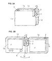
FIG. 1A is a rear view of a first example of the first
embodiment. Viewfinder 4 may be retracted, when display unit
is used as a finder.
-
FIG. 1B is a front view of the first example of the first
embodiment. Viewfinder 4 is extracted, when display unit 5 is
not used as a finder.
-
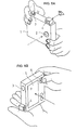
FIG. 2A is a front view of a second example of the first
embodiment. Viewfinder 4 is extracted, when display unit is
not used as a finder.
-
FIG. 2B is a front view during unfolding the apparatus of the
second example of the first embodiment.
-
FIG. 2C is a front view of the second example of the first
embodiment. Viewfinder 4 is retracted, when display unit 1b
on flat case lx is used as a finder.
-
FIG. 3A is a front view of a third example of the first
embodiment. Viewfinder 4 is fixed.
-
FIG. 3B is a front view during unfolding of the third example
of the first embodiment.
-
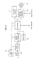
FIG. 4 is a block diagram showing the configuration of the
first embodiment.
-
FIG. 5A is an illustration how to take a picture, by using a
viewfinder 4 and a shutter 3.
-
FIG. 5B is an illustration how to take a picture, by using a
display unit 5 and a scroll button 6 as a shutter.
-
FIG. 6 is a rear view of a first example of the second
embodiment. Display unit 1b is used as a finder, while scroll
button 6 also functions as a shutter button.
-
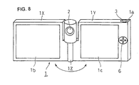
FIG. 7 is a front view schematic perspective view showing a
second example of the second embodiment. Shutter button 3 is
placed as conventional optical cameras.
-
FIG. 8 is an unfolded view of the second example as shown in
Figure 7.
-
FIG. 9 is a block diagram showing the configuration of the
second embodiment.
-
FIG. 10A is a front view of a first example of the third
embodiment. Display unit lc is a finder for a subject person.
-
FIG. 10B is an unfolded view of the first example as shown
in Figure 10A.
-
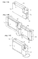
FIG. 11A is a rear view of a second example of the third
embodiment. Shutter button 3 is placed as conventional
optical cameras.
-
FIG. 11B is an unfolded view of the second example as
shown in Figure 11A.
-
FIG. 11C is a front view of the second example of the third
embodiment. Display unit lc is a finder for a subject person.
-
FIG. 12 is a block diagram showing the configuration of the
third embodiment.
First Embodiment
-
In a first example of the first embodiment as shown in FIG.
1A, the information terminal body 1 is equipped with a camera
function unit (not shown), and an operation button 3 for a
shutter arranged in a photographing optical system 2 (optical
lens system, electric eye photocell or the like) is arranged on a
shoulder portion la (upper side) of a case of the information
terminal body 1.
-
In particular, according to the present invention, a
viewfinder 4 is arranged in the shoulder portion la in
alignment with the operation button 3 to cause a user to peek
in, for example, a direct image from an optical path of the
optical system 2 such that the viewfinder can be retracted in
the information terminal body 1. In FIG. 1A, reference
numeral 5 denotes a display unit (liquid crystal screen)
arranged on one surface of the information terminal body 1,
and a terminal operation button 6 serving as a scroll button
related to the display unit 5 is arranged beside the display unit
5.
-
The terminal operation button 6 is designed such that two
operation functions are added by pressing the terminal
operation button 6 in two steps independently of a tilting
operation for a scroll operation (to be described later).
-
The information terminal body 1 shown in FIGS. 2A, 2B and
2C is designed to foldably pivot a pair of flat cases 1X and 1Y
at least one (two, in this example) of which has display units
1b and 1c through a hinge portion 1Z. A housing 7 equipped
with the photographing optical system 2 (lens opening is shown
outside) of the camera function unit is arranged on the hinge
portion 1Z such that the housing 7 can be pivoted about the
rotation center of the hinge portion 1Z.
-
Here, the viewfinder 4 is arranged in an optical system
storage unit (large-diameter portion which can be rotated
about the shaft) of the hinge portion 1Z such that the
viewfinder can be retracted in the optical system storage unit.
-
In a third example as shown in FIGS. 3A and 3B, the
viewfinder 4 is directly and fixedly arranged in the optical
system storage unit.
-
Here, the positions of the shutter button 3 for the shutter
and the viewfinder 4 are set at the positions shown in FIG. 2 or
3. However, the shutter button 3 and the viewfinder 4 may be
located any positions where the shutter button 3 and the
viewfinder 4 can be easily operated as buttons of a camera.
-
In these examples, each of the shutter button 3 (shutter
release button) and the scroll button 6 has a button switch
structure of a two-step pressing type. When each button is
pressed in the first step, like a conventional camera, the
camera function unit is activated to set the device in a
photographing preparation stage. When the button is pressed
in the second step, the shutter is released.
-
In this case, when the shutter button 3 or the scroll button 6
is pressed down by one step, as shown in FIG. 4, a control
circuit 11 controls a lens drive unit 12 to adjust a focal point
and an exposure of the photographing optical system 2 (optical
lens system), and the control circuit 11 controls an image
signal processing circuit 13 and a photographing circuit 14 to
perform such an adjustment that a proper image can be
photographed and completes preparation for photographing.
-
When the shutter button 3 or the scroll button 6 is pressed
down by two steps, the signal is input to the control circuit 11,
and the shutter (not shown) of the photographing optical
system 2 is released. Image information focused by the
photographing circuit 14 is converted into digital image data
by the image signal processing circuit 13 to be stored in a
memory 15.
-
In this case, the control circuit 11 is connected to a main
circuit of the portable information terminal. Digital image
data stored in the memory 15 is transferred to the main circuit
through the control circuit 11. In this case, an image may be
displayed on the display unit 1b.
-
In the portable information terminals having the
configurations shown in FIGS. 2 and 3, the following
configuration may be used. That is, for example, the case 1Y
is developed at 360° with respect to the case 1X, image display
is performed on the display unit 1b as a viewfinder. The
display unit lc is caused to face a subject side, and the same
screen display is performed on the display unit 1c, so that the
image (so-called camera angle) as a subject can be watched
from the subject side.
-
In this configuration, when photographing is performed with
a vertically long or horizontally long screen as a camera by
changing the holding state of the terminal body 1 (see FIGS.
5A and 5B), it is advantageous that the shutter button 3
serving as a shutter release button and the scroll button 6 are
easily selectively operated even if a user peeks in the
viewfinder 4 or even if the user watches the display unit 5 (or
1c).
-
In this example, the scroll button 6 is designed to be used in
not only a shutter operation function (press down) but also a
screen scroll operation or a menu selection operation which is
an original function. For this reason, the scroll button 6 is
connected to the control circuit 11 and also connected to the
main circuit of the portable information terminal. In the
portable information terminal, in order to make it possible to
also set the function when the scroll button 4 is vertically
pressed down in a function except for the shutter operation
function, a scroll button control circuit 16 which can perform
an operation such as a function mode switching operation may
be arranged. However, when the function when the scroll
button is vertically pressed down is set in only the shutter
operation function, the scroll button control circuit 16 may be
omitted.
-
The portable information terminal can achieve the function
of a television telephone or the like which is the original
function. For example, in the case of the configuration shown
in FIGS. 2 and 3, in the folded state shown in FIG. 2A or 3A,
only a reception state (which can also be actively turned off by
the switching operation) and a camera function are set. The
function of the information terminal is set such that a
reception signal of the information terminal can be notified by
generating a predetermined sound, and the shutter operation
of the camera function unit is performed by a pressing
operation of the shutter button 3.
-
In this case, a user arbitrary selects whether the display unit
1b is used as a viewfinder or the viewfinder 4 is directly used.
A switching operation for this selection may be performed by a
switch (not shown) arranged on the terminal body. When the
viewfinder 4 is directly used, the screen display (output display
as the function of the viewfinder) of the display unit 1b is
stopped, unnecessary power is prevented from being consumed.
-
As shown in FIGS. 2B and 3B, in a developed state of the
cases 1X and 1Y (for example, a mode turnover switch function
for converting the mode from a camera function mode to an
information terminal function mode is achieved), functions
(switching function to a transmission/reception state, function
for turning on the display units 1b and 1c, and the like) of the
information terminal are set.
-
Here, a function switch such as a keyboard display is
displayed on a part of the display unit 1b, while a call is made
by the scroll button 6.
-
In this state, the transmission and reception of sound can be
realized, and the camera function unit is operated to
continuously or intermittently photograph the image of a user
herself/himself through the photographing optical system 2.
For example, an image is displayed on a part of the display
unit 1b, and an image signal is digitized and then it is
transmitted to a person on the opposite end of line. An image
of the person on the opposite end of line is also displayed on the
display unit 1c.
-
On the demand of the called person or calling person, the
camera function is achieved by using the photographing optical
system 2, and the image can also be immediately transmitted
to the other end. Such a mode switching operation may be
performed by a function switch displayed on a part of the
display unit 1b or the like.
-
In the portable information terminal with camera according
to the present invention, when the camera function is mainly
operated, even if the display unit 1b of the portable
information terminal is powered on to be used as a viewfinder,
the viewfinder 4 which is independently arranged can be used
in correspondence with the photographing optical system 2 of
the camera function unit. For this reason, a power for
powering the display unit 1b can be prevented from being
consumed.
-
In these examples, the vertical press switch function set in
the scroll button 6 can also be used in a function except for the
shutter operation button (multiple function) to the taste of a
user.
Second Embodiment
-
The outlines of two examples of the second embodiment are
shown in FIGS. 6, 7, and 8. In the-first example as shown in
FIG. 6, an information terminal body 1 is equipped with a
camera function unit (not shown), an shutter operation button
3 for a shutter arranged in a photographing optical system 2
(optical lens system, electric eye photocell, and the like) is
arranged on a shoulder portion 1a (located on a surface
perpendicular to a surface having a display unit to be described
later) of a case of the information terminal body 1.
-
In particular, the same function as that of the shutter
operation button 3 for the shutter is set in one function
operation of a terminal operation button 6 arranged on the
information terminal body 1, so that the terminal operation
button 6 and the shutter operation button 3 can be used by
switching. In this example, the terminal operation button 6 is
a scroll button related to the display unit 1b of the information
terminal body 1. This scroll button has not only a scroll
function obtained by a normal tilting operation but also a
vertical pressing function, and the function is caused to
correspond to the function of the shutter operation button 3 for
the shutter (the terminal operation button 6 and the shutter
operation button 3 have the same functions).
-
The second example of information terminal body 1 as shown
in FIGS. 7 and 8 is designed to foldably pivot a pair of flat
cases 1X and 1Y at least one (two, in this example) of which
has display units 1c and 1d through a hinge portion 1Z. The
hinge portion 1Z is equipped with the photographing optical
system 2 of the camera function unit. The characteristic
feature of the present invention is the same as that of the
configuration shown in FIG. 6.
-
Here, the positions of the shutter operation button 3 for the
shutter and the scroll button 6 are set at the positions shown
in FIG. 8.
-
However, the shutter operation button 3 and the scroll
button 4 may be located at any positions. The shutter
operation button 3 may be located at a position where the
information terminal is easily operated as a camera, and the
scroll button 6 may be located at a position where the scroll
button is is easily operated as the shutter release button of the
camera and is easily operated as the operation button of the
portable information terminal.
-
Each of the shutter operation button 3 (shutter release
5 button) and the scroll button 6 has a button switch structure of
a two-step pressing type. As for the former, when each button
is pressed in the first step, like a conventional camera, the
camera function unit is activated to set the device in a
photographing preparation stage. When the button is pressed
in the second step, the shutter is released.
-
In this case, when the shutter operation button 3 or the
scroll button 6 is pressed down by one step, as shown in FIG. 9,
a control circuit 11 comprising of a CPU and the like controls
a lens drive unit 12 to adjust a focal point and an exposure of
the photographing optical system 2 (optical lens system), and
the control circuit 11 controls an image signal processing
circuit 13 and a image-pickup circuit 14 to perform such an
adjustment that a proper image can be photographed and
completes preparation for photographing.
-
When the shutter operation button 3 or the scroll button 6 is
pressed down by two steps, the signal is input to the control
circuit 11, and the shutter (not shown) of the photographing
optical system 2 is released. Image information focused by
the image-pickup circuit 14 is converted into digital image data
by the image signal processing circuit 13 to be stored in a
memory 15.
-
In this case, the control circuit 11 is connected to a main
circuit of the portable information terminal. Digital image
data stored in the memory 15 is transferred to the main circuit
through the control circuit 11. In this case, an image may be
displayed on the display unit 1b.
-
In the portable information terminals having the
configurations shown in FIGS. 7 and 8, the following
configuration may be used. That is, for example, the case 1Y
is developed at 360° with respect to the case 1X, image display
is performed on the display unit 1b as a viewfinder. The
display unit 1c is caused to face a subject side, and the same
screen display is performed on the display unit 1c, so that the
image (so-called camera angle) as a subject can also be watched
from the subject (person to be photographed) side. In this
manner, the image of the person to be photographed can be
checked.
-
In this example, the scroll button 6 is designed to be used in
not only a shutter operation function (press down) but also a
screen scroll operation or a menu selection operation which is
an original function. For this reason, the scroll button 6 is
connected to the control circuit 11 and also connected to the
main circuit of the portable information terminal. In the
portable information terminal, in order to make it possible to
also set the function when the scroll button 4 is vertically
pressed down in a function except for the shutter operation
function, a scroll button control circuit 16 which can perform
an operation such as a function mode switching operation may
be arranged. However, when the function when the scroll
button is vertically pressed down is set in only the shutter
operation function, the scroll button control circuit 16 may be
omitted.
-
In this example, the scroll button 6 is designed to be used in
not only a shutter operation function (press down) but also a
screen scroll operation or a menu selection operation which is
an original function. For this reason, the scroll button 6 is
connected to the control circuit 11 and also connected to the
main circuit of the portable information terminal. In the
portable information terminal, in order to make it possible to
also set the function when the scroll button 6 is vertically
pressed down in a function except for the shutter operation
function, a scroll button control circuit 16 which can perform
an operation such as a function mode switching operation may
be arranged. However, when the function when the scroll
button is vertically pressed down is set in only the shutter
operation function, the scroll button control circuit 16 may be
omitted.
-
The portable information terminal can achieve the function
of a television telephone or the like which is the original
function. For example, in the case of the configuration shown
in FIGS. 7 and 8, in the folded state shown in FIG. 7, only a
reception state (which can also be actively turned off by the
switching operation) and a camera function are set. The
function of the information terminal is set such that a
reception signal can be notified by generating a predetermined
sound, and the shutter operation of the camera function unit is
performed by a pressing operation of the operation button 3.
-
As shown in FIG. 8, in a developed state of the cases 1X and
1Y (for example, a mode turnover switch function for
converting the mode from a camera function mode to an
information terminal function mode is achieved), functions
(switching function to a transmission/reception state, function
for turning on the display units 1b and 1c, and the like) of the
information terminal are set.
-
Here, for example, a function switch such as a keyboard
display is displayed on a part of the display unit 1b, while a
call is made by using scroll button.
-
In this state, the transmission and reception of sound can be
realized, and the camera function unit is operated to
continuously or intermittently photograph the image of a user
herself/himself through the photographing optical system 2.
For example, an image is displayed on a part of the display
unit 1b, and an image signal is digitized and then transmitted
to a person on the other end of line. An image of the person
on the other end of line can also be displayed on the display
unit 1c.
-
On the demand of a calling person or a called person, the
photographing optical system 2 is activated, and the image can
also be immediately transmitted to the other end. Such a
mode switching operation may be performed by a function
switch serving as a touch sensor displayed on a part of the
display unit 1b or the like.
-
In the portable information terminal with camera according
to the present invention, even though the camera function is
mainly operated, or when the original function of the portable
information terminal is mainly used, an advantage that a
button (for example, scroll button) operated by a user is used
as an operation button for a shutter operation can be achieved.
-
In addition, the vertically pressing switching function set in
the scroll button can also be used in a function except for the
shutter operation button (multiple function) to the taste of a
user.
-
In many conventional portable information terminals with
camera, shutter release buttons are independent of other
buttons. Therefore, when a user wants to photograph a
subject with the camera while a scroll button is being operated,
the user changes the holding state of the device body or the
user must separate her/his finger from the scroll button and
move the finger to the operation button for the shutter.
-
Furthermore, when a photographing operation is performed
with a vertically long screen or a horizontally long screen, the
same actions as described above must be performed to change
the position of the camera.
-
Although a shutter operation function is added to the scroll
button serving as a terminal operation button, a shutter
operation can also be realized without using the scroll button.
The shutter operation can also be achieved by operating a
plurality of buttons 5 as shown in FIG. 6.
Third Embodiment
First Example
-
In this example, the information terminal body 1 is designed
such that, as shown in FIGS. 10A, 10B, a pair of flat cases 1X
and 1Y having display units 1b and lc are foldably pivoted
through a hinge portion 1Z, and the hinge portion 1Z is
equipped with a photographing optical system 2 (lens opening
is shown outside) for the camera function unit. One case 1X is
equipped with a terminal operation button 6 as a scroll button
for a screen of the display unit 1b, and the terminal operation
button 6 is aligned to another terminal operation button 5.
The terminal operation button 5 is designed (to be described
later) such that not only a tilting operation for a scroll
operation in a normal state but also two operation functions
obtained by pressing the button in two steps.
-
In particular, here, the cases 1X and 1Y have the display
units on the outside surfaces such that the display units 1b
and 1c face outside (the display units 1b and 1c are back to
back on the opposite side) in a folded state. The hinge portion
1Z is designed to pivot a hinge portion 1d arranged on the case
1X and a hinge portion le arranged on the case 1Y with respect
to the axial center (not shown) of a housing which
accommodates the optical system 2 therein.
-
Here, the position of the operation button 3 for the shutter is
located at the shoulder portion la shown in FIG. 10. However,
the information terminal body 1 may be arranged at any
position where the portable information terminal can be easily
operated.
-
In these examples, each of the shutter operation button 3
(shutter release button) and the scroll button 6 has a button
switch structure of a two-step pressing type. When each
button is pressed in the first step, like a conventional camera,
the camera function unit is activated to set the device in a
photographing preparation stage. When the button is pressed
in the second step, the shutter is released.
-
In this case, in the state in FIG. 10A (folded state), when the
shutter operation button 3 or the scroll button 6 is pressed
down by one step, as shown in FIG. 12, a control circuit 11
controls a lens drive unit 12 to adjust a focal point and an
exposure of the photographing optical system 2 (optical lens
system), and the control circuit 11 controls an image signal
processing circuit 13 and a photographing circuit 14 to perform
such an adjustment that a proper image can be photographed
and completes preparation for photographing.
-
When the shutter operation button 3 or the scroll button 6 is
pressed down by two steps, the signal is input to the control
circuit 11, and the shutter (not shown) of the photographing
optical system 2 is released. Image information focused by
the photographing circuit 14 is converted into digital image
data by the image signal processing circuit 13 to be stored in a
memory 15.
-
In this case, the control circuit 11 is connected to a main
circuit of the portable information terminal. Digital image
data stored in the memory 15 is transferred to the main circuit
through the control circuit 11. In this case, the image of a
subject is displayed on the display unit 1b in place of a
viewfinder.
-
Here, Images are displayed on the display unit 1b as a finder,
and the display unit 1c is caused to face the subject. The
same image is displayed on the display unit 1c, so that an
image (so-called camera angle) which is a subject can be
viewed from the subject side. In this case, a horizontally
inverted image (for example, this is obtained by operating a
line memory as so-called First in last out) of the photographed
image may be displayed on the display unit 1c facing the
subject side. For this reason, the portable information
terminal may have a selectable and switchable configuration
(not shown) such as switching means for a normal image such
that an inverted image is displayed through image inversion
means 16.
-
In this example, the scroll button 6 is designed to be used in
not only a shutter operation function (press down) but also a
screen scroll operation or a menu selection operation which is
an original function. For this reason, the scroll button 6 is
connected to the control circuit 11 and also connected to the
main circuit of the portable information terminal. In the
portable information terminal, in order to make it possible to
also set the function when the scroll button 6 is vertically
pressed down in a function except for the shutter operation
function, a scroll button control circuit 17 which can perform
an operation such as a function mode switching operation may
be arranged. However, when the function when the scroll
button is vertically pressed down is set in only the shutter
operation function, the scroll button control circuit 17 may be
omitted.
-
The portable information terminal can achieve the function
of a television telephone or the like which is the original
function. For example, in the folded state shown in FIG. 10A,
only a reception state (which can also be actively turned off by
the switching operation) and a camera function are set. The
function of the information terminal is set such that a
reception signal of the information terminal can be notified by
generating a predetermined sound, and the shutter operation
of the camera function unit is performed by a pressing
operation of the shutter operation button 3. In this case, the
display unit 1b is used as a finder.
-
As shown in FIG. 10B, in a developed state of the cases 1X
and 1Y (for example, a mode turnover switch function for
converting the mode from a camera function mode to an
information terminal function mode is achieved), functions
(switching function to a transmission/reception state, function
for turning on the display units 1b and 1c, and the like) of the
information terminal are set.
-
Here, for example, a function switch such as a keyboard
display is displayed on a part of the display unit 1b, while the
scroll button 6 is operated to make a call.
-
In this state, the transmission and reception of sound can be
realized, and the camera function unit is operated to
continuously or intermittently photograph the image of a user
herself/himself through the photographing optical system 2.
For example, an image is displayed on a part of the display
unit 1b, and an image signal is digitized and then transmitted
to a person on the other end of line, or radio communication
channel. An image of the person on the other end can also be
displayed on the display unit 1c.
-
In a communication process, on the demand from the calling
side or called side, the camera function is achieved for a subject
on the other side, a desired photographing operation is
performed by using the photographing optical system 2, and
the image can also be immediately transmitted from one end to
the other end. Such a mode switching operation may be
performed by a function switch displayed on a part of the
display unit 1b or the like. In this case, as shown in FIG. 10A
and FIG. 11C, when the display unit 1c is caused to face a
subject to perform a photographing operation, for example, so
that the shutter can be released after a user causes a person
(person to be photographed), which is a subject, to check the
image. The photographing operation can be performed at a
preferable camera angle, and the image can be transmitted.
-
In the portable information terminal with camera, when the
camera function is mainly operated, an image to be
photographed can be checked, and an image on which the
intention, e.g., a camera angle or the like, of a person to be
photographed is reflected can be received.
Second Example
-
In this example, a hinge portion 1Z has a structure in which
cases 1X and 1Y are pivoted by parallel shafts1f and 1g
(indicated by dotted lines) with respect to a housing 6 equipped
with a photographing optical system 2. As the folded states,
two states can be selected such that display units 1b and 1c
face outside and inside the device.
-
More specifically, when the portable information terminal is
not used, as shown in FIG. 11A, the device is designed such
that the display units 1b and 1c are opposite to each other and
are not exposed to the outside. As shown in FIG. 11B, when
the portable information terminal is used as an information
terminal, one case 1X is developed at 180° about the parallel
shaft 1f with respect to the other case 1Y (state indicated by a
solid line), or, furthermore, when the cases 1X and 1Y are
horizontally drawn as indicated by a straight arrow to rotate
the housing 6 at 90° about an intermediate point between the
parallel shafts 1f and 1g (state indicated by an imaginary line).
-
In this state, as in the first example, for example, the portable
information terminal can be used as a television telephone.
-
In particular, in this example, when the cases 1X and 1Y are
pivoted by the two parallel shafts 1f and 1g, the housing 6 is
more rotated at 90° (rotated at 180° from the state shown in
FIG. 11A) from the state shown in FIG. 11a through the state
shown in FIG. 11b. In addition, the case 1Y is rotated at 180°
about the parallel shaft 1g (i.e., rotated at 360° as a whole), so
that the display units 1b and 1c can be made opposite to each
other as shown in FIG. 11C. Therefore, the image of a subject
can be displayed on the display unit 1b as a viewfinder, and
the same image or a horizontally inverted image can be
displayed to be opposite to the display unit 1b used as a finder
on the opposite side can be displayed on the display unit 1c
facing the subject. For this reason, a photographing operation
can be performed with an image on which a demand, related to
a camera angle, of a person to be photographed is reflected.
-
In these examples, the vertical press switch function set in
the scroll button 6 can also be used in a function except for the
shutter operation button (multiple function) to the taste of a
user. In addition, the following method of using the portable
information terminal can be achieved. That is, the camera
function is operated when the cases are developed at 180°, a
live image serving as a viewfinder is displayed on one display
unit, and the image which is previously photographed is
displayed.