EP1110528A2 - Absorbent article with multiple high absorbency zones - Google Patents
Absorbent article with multiple high absorbency zones Download PDFInfo
- Publication number
- EP1110528A2 EP1110528A2 EP00127842A EP00127842A EP1110528A2 EP 1110528 A2 EP1110528 A2 EP 1110528A2 EP 00127842 A EP00127842 A EP 00127842A EP 00127842 A EP00127842 A EP 00127842A EP 1110528 A2 EP1110528 A2 EP 1110528A2
- Authority
- EP
- European Patent Office
- Prior art keywords
- absorbent
- high absorbency
- zone
- absorbent element
- absorbency zone
- Prior art date
- Legal status (The legal status is an assumption and is not a legal conclusion. Google has not performed a legal analysis and makes no representation as to the accuracy of the status listed.)
- Granted
Links
Images


Classifications
-
- A—HUMAN NECESSITIES
- A61—MEDICAL OR VETERINARY SCIENCE; HYGIENE
- A61F—FILTERS IMPLANTABLE INTO BLOOD VESSELS; PROSTHESES; DEVICES PROVIDING PATENCY TO, OR PREVENTING COLLAPSING OF, TUBULAR STRUCTURES OF THE BODY, e.g. STENTS; ORTHOPAEDIC, NURSING OR CONTRACEPTIVE DEVICES; FOMENTATION; TREATMENT OR PROTECTION OF EYES OR EARS; BANDAGES, DRESSINGS OR ABSORBENT PADS; FIRST-AID KITS
- A61F13/00—Bandages or dressings; Absorbent pads
- A61F13/15—Absorbent pads, e.g. sanitary towels, swabs or tampons for external or internal application to the body; Supporting or fastening means therefor; Tampon applicators
- A61F13/53—Absorbent pads, e.g. sanitary towels, swabs or tampons for external or internal application to the body; Supporting or fastening means therefor; Tampon applicators characterised by the absorbing medium
- A61F13/531—Absorbent pads, e.g. sanitary towels, swabs or tampons for external or internal application to the body; Supporting or fastening means therefor; Tampon applicators characterised by the absorbing medium having a homogeneous composition through the thickness of the pad
- A61F13/532—Absorbent pads, e.g. sanitary towels, swabs or tampons for external or internal application to the body; Supporting or fastening means therefor; Tampon applicators characterised by the absorbing medium having a homogeneous composition through the thickness of the pad inhomogeneous in the plane of the pad
- A61F13/533—Absorbent pads, e.g. sanitary towels, swabs or tampons for external or internal application to the body; Supporting or fastening means therefor; Tampon applicators characterised by the absorbing medium having a homogeneous composition through the thickness of the pad inhomogeneous in the plane of the pad having discontinuous areas of compression
-
- A—HUMAN NECESSITIES
- A61—MEDICAL OR VETERINARY SCIENCE; HYGIENE
- A61F—FILTERS IMPLANTABLE INTO BLOOD VESSELS; PROSTHESES; DEVICES PROVIDING PATENCY TO, OR PREVENTING COLLAPSING OF, TUBULAR STRUCTURES OF THE BODY, e.g. STENTS; ORTHOPAEDIC, NURSING OR CONTRACEPTIVE DEVICES; FOMENTATION; TREATMENT OR PROTECTION OF EYES OR EARS; BANDAGES, DRESSINGS OR ABSORBENT PADS; FIRST-AID KITS
- A61F13/00—Bandages or dressings; Absorbent pads
- A61F13/15—Absorbent pads, e.g. sanitary towels, swabs or tampons for external or internal application to the body; Supporting or fastening means therefor; Tampon applicators
- A61F13/53—Absorbent pads, e.g. sanitary towels, swabs or tampons for external or internal application to the body; Supporting or fastening means therefor; Tampon applicators characterised by the absorbing medium
- A61F13/534—Absorbent pads, e.g. sanitary towels, swabs or tampons for external or internal application to the body; Supporting or fastening means therefor; Tampon applicators characterised by the absorbing medium having an inhomogeneous composition through the thickness of the pad
-
- A—HUMAN NECESSITIES
- A61—MEDICAL OR VETERINARY SCIENCE; HYGIENE
- A61F—FILTERS IMPLANTABLE INTO BLOOD VESSELS; PROSTHESES; DEVICES PROVIDING PATENCY TO, OR PREVENTING COLLAPSING OF, TUBULAR STRUCTURES OF THE BODY, e.g. STENTS; ORTHOPAEDIC, NURSING OR CONTRACEPTIVE DEVICES; FOMENTATION; TREATMENT OR PROTECTION OF EYES OR EARS; BANDAGES, DRESSINGS OR ABSORBENT PADS; FIRST-AID KITS
- A61F13/00—Bandages or dressings; Absorbent pads
- A61F13/15—Absorbent pads, e.g. sanitary towels, swabs or tampons for external or internal application to the body; Supporting or fastening means therefor; Tampon applicators
- A61F13/53—Absorbent pads, e.g. sanitary towels, swabs or tampons for external or internal application to the body; Supporting or fastening means therefor; Tampon applicators characterised by the absorbing medium
- A61F2013/530481—Absorbent pads, e.g. sanitary towels, swabs or tampons for external or internal application to the body; Supporting or fastening means therefor; Tampon applicators characterised by the absorbing medium having superabsorbent materials, i.e. highly absorbent polymer gel materials
- A61F2013/53051—Absorbent pads, e.g. sanitary towels, swabs or tampons for external or internal application to the body; Supporting or fastening means therefor; Tampon applicators characterised by the absorbing medium having superabsorbent materials, i.e. highly absorbent polymer gel materials being only in particular parts or specially arranged
- A61F2013/530532—Absorbent pads, e.g. sanitary towels, swabs or tampons for external or internal application to the body; Supporting or fastening means therefor; Tampon applicators characterised by the absorbing medium having superabsorbent materials, i.e. highly absorbent polymer gel materials being only in particular parts or specially arranged the maximum being at certain depth in the thickness
-
- A—HUMAN NECESSITIES
- A61—MEDICAL OR VETERINARY SCIENCE; HYGIENE
- A61F—FILTERS IMPLANTABLE INTO BLOOD VESSELS; PROSTHESES; DEVICES PROVIDING PATENCY TO, OR PREVENTING COLLAPSING OF, TUBULAR STRUCTURES OF THE BODY, e.g. STENTS; ORTHOPAEDIC, NURSING OR CONTRACEPTIVE DEVICES; FOMENTATION; TREATMENT OR PROTECTION OF EYES OR EARS; BANDAGES, DRESSINGS OR ABSORBENT PADS; FIRST-AID KITS
- A61F13/00—Bandages or dressings; Absorbent pads
- A61F13/15—Absorbent pads, e.g. sanitary towels, swabs or tampons for external or internal application to the body; Supporting or fastening means therefor; Tampon applicators
- A61F13/53—Absorbent pads, e.g. sanitary towels, swabs or tampons for external or internal application to the body; Supporting or fastening means therefor; Tampon applicators characterised by the absorbing medium
- A61F2013/530481—Absorbent pads, e.g. sanitary towels, swabs or tampons for external or internal application to the body; Supporting or fastening means therefor; Tampon applicators characterised by the absorbing medium having superabsorbent materials, i.e. highly absorbent polymer gel materials
- A61F2013/53051—Absorbent pads, e.g. sanitary towels, swabs or tampons for external or internal application to the body; Supporting or fastening means therefor; Tampon applicators characterised by the absorbing medium having superabsorbent materials, i.e. highly absorbent polymer gel materials being only in particular parts or specially arranged
- A61F2013/530547—Absorbent pads, e.g. sanitary towels, swabs or tampons for external or internal application to the body; Supporting or fastening means therefor; Tampon applicators characterised by the absorbing medium having superabsorbent materials, i.e. highly absorbent polymer gel materials being only in particular parts or specially arranged positioned in a separate layer or layers
- A61F2013/530562—Absorbent pads, e.g. sanitary towels, swabs or tampons for external or internal application to the body; Supporting or fastening means therefor; Tampon applicators characterised by the absorbing medium having superabsorbent materials, i.e. highly absorbent polymer gel materials being only in particular parts or specially arranged positioned in a separate layer or layers being arranged in discontinuous pattern
-
- A—HUMAN NECESSITIES
- A61—MEDICAL OR VETERINARY SCIENCE; HYGIENE
- A61F—FILTERS IMPLANTABLE INTO BLOOD VESSELS; PROSTHESES; DEVICES PROVIDING PATENCY TO, OR PREVENTING COLLAPSING OF, TUBULAR STRUCTURES OF THE BODY, e.g. STENTS; ORTHOPAEDIC, NURSING OR CONTRACEPTIVE DEVICES; FOMENTATION; TREATMENT OR PROTECTION OF EYES OR EARS; BANDAGES, DRESSINGS OR ABSORBENT PADS; FIRST-AID KITS
- A61F13/00—Bandages or dressings; Absorbent pads
- A61F13/15—Absorbent pads, e.g. sanitary towels, swabs or tampons for external or internal application to the body; Supporting or fastening means therefor; Tampon applicators
- A61F13/53—Absorbent pads, e.g. sanitary towels, swabs or tampons for external or internal application to the body; Supporting or fastening means therefor; Tampon applicators characterised by the absorbing medium
- A61F2013/530481—Absorbent pads, e.g. sanitary towels, swabs or tampons for external or internal application to the body; Supporting or fastening means therefor; Tampon applicators characterised by the absorbing medium having superabsorbent materials, i.e. highly absorbent polymer gel materials
- A61F2013/5307—Absorbent pads, e.g. sanitary towels, swabs or tampons for external or internal application to the body; Supporting or fastening means therefor; Tampon applicators characterised by the absorbing medium having superabsorbent materials, i.e. highly absorbent polymer gel materials characterized by the quantity or ratio of superabsorbent material
-
- Y—GENERAL TAGGING OF NEW TECHNOLOGICAL DEVELOPMENTS; GENERAL TAGGING OF CROSS-SECTIONAL TECHNOLOGIES SPANNING OVER SEVERAL SECTIONS OF THE IPC; TECHNICAL SUBJECTS COVERED BY FORMER USPC CROSS-REFERENCE ART COLLECTIONS [XRACs] AND DIGESTS
- Y10—TECHNICAL SUBJECTS COVERED BY FORMER USPC
- Y10T—TECHNICAL SUBJECTS COVERED BY FORMER US CLASSIFICATION
- Y10T428/00—Stock material or miscellaneous articles
- Y10T428/249921—Web or sheet containing structurally defined element or component
Definitions
- the present invention relates to a novel absorbent article such as a sanitary napkin having an absorbent structure which is characterized by having multiple integral high absorbency zones disposed within its thickness.
- Absorbent structures are known for inclusion in disposable absorbent articles used for absorbing body fluids and other exudates.
- Such absorbent structures have traditionally been made from readily available and relatively inexpensive materials such as cotton fibers, wood pulp fluff, cellulosic tissue or wadding, or other absorbent fibers. These materials have provided satisfactory absorbency of fluids both in terms of absorbency rate and overall absorbent capacity.
- absorbent structures made from such materials may tend to collapse when wetted, thereby losing some of their void volume.
- Such structures may also allow absorbed fluid to be squeezed back out of the structure onto the user of the absorbent article.
- When such structures have absorbed fluid they may present an uncomfortable wet feeling against the skin of the user.
- superabsorbent polymer particles have been combined with the more traditional absorbent materials to provide structures with enhanced absorbency and retention, which may help to eliminate the above problems. Replacement of traditional absorbent materials with superabsorbent polymer particles may also allow for absorbent products to be thinner while retaining the absorbent capacity of thicker, bulkier products.
- superabsorbent polymer particles tend to swell as they absorb fluid, they may cause what is commonly known as gel-blocking. In other words, as fluid is absorbed by the particles of superabsorbent polymer, those particles swell and may form an occlusive layer of swollen superabsorbent particles. This occlusive layer then prevents the passage of additional fluid into the structure. Thus, the superabsorbent polymer particles must be properly placed within an absorbent structure to allow for this swelling and to most fully utilize their absorbent capacity.
- an absorbent structure with good absorbency and retention of fluid. What is also needed is an absorbent structure that helps to provide a dry feel to the skin of a user when used in an absorbent article. What is further needed is an absorbent structure with superabsorbent polymer particles spaced and placed within the structure to most fully utilize the absorbency and retention capabilities of the superabsorbent polymer particles.
- the absorbent structure includes an absorbent element having an integral structure formed from absorbent fibers and super absorbent particles.
- the absorbent structure may optionally include additional laminate layers such as one or more layers of tissue and/or a nonwoven fabric.
- the nonwoven fabric may have a lower density and a higher porosity than the absorbent element of the invention to allow for rapid fluid acquisition and the subsequent transfer of the acquired fluid to an adjacent, slower absorbing, higher density absorbent element.
- the nonwoven fabric may have a higher density and a lower porosity than the absorbent element to increase fluid wicking throughout the nonwoven fabric.
- lower-density nonwoven fabrics are placed adjacent the body-facing surface of an absorbent element, and higher-density nonwoven fabrics are placed adjacent the garment-facing surface of an absorbent element.
- the absorbent structure of the invention has peripheral edges and a center region.
- the center region is that portion of the structure which is inward from the peripheral edges of the structure and which is intended to accept incoming fluid when the structure is used in an absorbent article.
- the absorbent element also has peripheral edges and a center region (as described above). The peripheral edges of the absorbent element may be coterminous with the peripheral edges of the absorbent structure or may be inward from or extend beyond the peripheral edges of the absorbent structure.
- the absorbent element has an upper surface and a lower surface defining therebetween an absorbent element thickness.
- the absorbent element further has an integral structure and further includes a first high absorbency zone and a second high absorbency zone separated from one another by a portion of the element thickness.
- Each of the first and second high absorbency zones comprises an integral mixture of absorbent fibers and superabsorbent polymer particles and has a first surface and a second surface.
- integral means a unitary structure wherein the absorbent fibers are intermeshed throughout the entire absorbent element.
- each of the high absorbency zones represents the location at which a transition occurs from a section of the integral structure substantially free of superabsorbent polymer particles to a section of the integral structure containing a mixture of absorbent fibers and superabsorbent polymer particles.
- the first surface of the first high absorbency zone may optionally be coplanar with the upper surface of the absorbent element, or alternatively, the first high absorbency zone may be below or spaced from the upper surface of the absorbent element wherein the upper surface is substantially free of superabsorbent polymer particles and contains only absorbent fibers.
- Subjacent to the first high absorbency zone is a second high absorbency zone, each zone having a respective thickness.
- the thickness of the first high absorbency zone may be the same as or different from the thickness of the second high absorbency zone.
- the thickness of each of the first and second high absorbency zones comprises less than about 35% of the thickness of the absorbent element.
- the thickness of each of the first and second high absorbency zones comprises less than 20% of the thickness of the absorbent element.
- the first high absorbency zone is separated from the second high absorbency zone by a portion of the absorbent element thickness which is substantially free of superabsorbent particles. Additionally, the portions of the absorbent element that are outside of the first and second high absorbency zones are substantially free of superabsorbent polymer particles.
- the superabsorbent polymer particles are mixed with absorbent fibers within the first and second high absorbency zones.
- the superabsorbent polymer particles are uniformly and homogeneously mixed with the absorbent fibers within the first and second high absorbency.
- the superabsorbent particles may be distributed within one or both of the first and second high absorbency zones on an increasing gradient wherein the concentration of superabsorbent particles increases from a minimum at the first surface of the high absorbency zone to a maximum at the second surface of the high absorbency zone, or a decreasing gradient, wherein the concentration of superabsorbent particles decreases from a maximum at the first surface of the high absorbency zone to a minimum at the second surface of the high absorbency zone.
- the superabsorbent particles can be distributed in a manner such that a maximum concentration of these particles occurs in a region centered at approximately half the distance between the first surface and the second surface of one or both of the high absorbency zones.
- the upper surface of the absorbent element is substantially free of superabsorbent particles, the first high absorbency zone being slightly below the upper surface of the absorbent element wherein the upper surface of the absorbent element comprises 100% absorbent pulp fibers.
- an absorbent structure utilized in absorbent articles such as sanitary napkins, diapers, incontinence articles and the like.
- An embodiment of such an article comprises the absorbent element of the invention contained between a liquid-permeable body-facing layer and a liquid-impermeable barrier layer and positioned such that the body-facing layer is adjacent the upper surface of the absorbent element and the impermeable barrier layer is adjacent the lower surface of the absorbent element.
- a novel apparatus for intermittently applying a particulate material to a substrate comprising two applicator valve assemblies, each applicator valve assembly comprising a stationary funnel having an opening and positioned within a moveable housing such that the moveable housing is free to move relative to the stationary funnel, the moveable housing comprising at least one slot opening and at least one recycle hole spaced from the slot opening, wherein the moveable housing moves relative to the stationary funnel to provide an application phase to allow passage of particulate material by free-fall through the stationary funnel opening and the slot opening when the stationary funnel opening aligns with the slot opening, and a recycle phase to prevent dispensing of particulate material onto the substrate when the stationary funnel opening aligns with the at least one recycle hole.
- Also provided in accordance with the present invention is a novel method for intermittently applying particulate material to a substrate comprising the steps of:
- Figure 1 is a sectional view of a first preferred embodiment of the absorbent element of the invention.
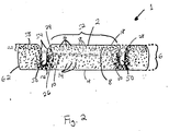
- Figure 2 is a sectional view of a second preferred embodiment of the absorbent element of the invention.
- Figure 3 is a sectional view of a third preferred embodiment of the absorbent element of the invention.
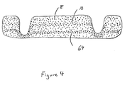
- Figure 4 is a sectional view of a fourth preferred embodiment of the absorbent element of the invention.
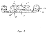
- Figure 5 is a sectional view of a fifth preferred embodiment of the absorbent element of the invention.
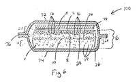
- Figure 6 is a sectional view of a first preferred embodiment of the absorbent article of the invention.
- Figure 7 is a sectional view of a second preferred embodiment of the absorbent article of the invention.
- Figure 8 is a perspective view of a preferred embodiment of an absorbent article of the invention.
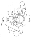
- Figure 9 is a schematic illustration of a preferred apparatus for making the absorbent element of the invention.
- Figure 10A is a detailed axial view of the particle rotary applicator of the apparatus shown in Figure 9 in the particle application phase.
- Figure 10B is a detailed side view of the particle rotary applicator of the apparatus shown in Figure 9 in the particle application phase.
- Figure 11A is a detailed axial view of the particle rotary applicator of the apparatus shown in Figure 9 in the recycle phase.
- Figure 11B is a detailed side view of the particle rotary applicator of the apparatus shown in Figure 9 in the recycle phase.
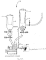
- Figure 12 is a detailed view of the gravimetric feeder and powder receivers to supply the particle rotary applicator of the apparatus shown in Figure 9.
- the present invention is directed to novel absorbent articles such as, for example, sanitary napkins, having a central absorbent structure adapted to receive and retain body exudates. More particularly, the absorbent articles of the present invention have a novel absorbent structure which includes an absorbent element having an integral structure formed from a combination of absorbent fibers and super absorbent particles and further including a first high absorbency zone located adjacent an upper surface of the absorbent element and a second high absorbency zone spaced below and vertically separated from the first high absorbency zone by a portion of the absorbent element thickness.
- the absorbent articles will generally have a body facing, liquid-permeable cover layer, a garment-facing, liquid-impermeable barrier layer, and an absorbent structure between the body-facing layer and the barrier layer.
- the absorbent structure may optionally include a multi-layer laminate structure having one or more layers of nonwoven fabrics and/or tissue in addition to the absorbent element.
- the absorbent structure comprises an upper, body facing fluid transfer layer formed from a nonwoven fabric and an underlying absorbent element between the fluid transfer layer and the barrier layer.
- the fluid transfer layer preferably has a porosity that is greater than the porosity of the absorbent element.
- the absorbent element has a center region and peripheral edges, and an upper surface and a lower surface defining therebetween an absorbent element thickness.
- the absorbent element has a first high absorbency zone having a first high absorbency zone first surface and a first high absorbency zone second surface separated by a first high absorbency zone thickness (hereinafter "first zone thickness”), and a second high absorbency zone having a second high absorbency zone first surface and a second high absorbency zone second surface separated by a second high absorbency zone thickness (hereinafter "second zone thickness").
- the first high absorbency zone first surface may optionally be coplanar with the upper surface of the absorbent element or alternatively it may be slightly below the upper surface wherein the region between the upper surface and the first high absorbency zone first surface is substantially free of superabsorbent particles.
- the second high absorbency zone is spaced below the first high absorbency zone such that the first high absorbency zone second surface is separated from the second high absorbency zone first surface by a portion of the absorbent element thickness which is substantially free of superabsorbent particles.
- the novel absorbent structure of the present invention is intended for use in disposable absorbent articles. These articles are adapted to be placed in a crotch portion of an undergarment and worn by the user in direct contact with the body for the purpose of absorbing body fluids and are subsequently thrown away after a single use.
- FIG. 1 there is shown a sectional view of a first preferred embodiment of the absorbent element 1 of the present invention.
- Figure 1 shows an integral absorbent element 1 with an upper surface 2 and a lower surface 4 defining therebetween an absorbent element thickness 6.
- the absorbent element further has a first high absorbency zone 8 and a second high absorbency zone 10 separated from one another by a portion 12 of the absorbent element thickness.
- Both the first high absorbency zone and the second high absorbency zone comprise a mixture of absorbent fibers 14 and superabsorbent polymer particles 16.
- the superabsorbent polymer particles are substantially contained within the first and second high absorbency zones, and the portion 12 of the absorbent element thickness separating the first and second high absorbency zones is substantially free of superabsorbent polymer particles.
- an upper surface 2 is substantially free of superabsorbent polymer particles 16, and that the superabsorbent polymer particles 16 are separated from one another by absorbent fibers 14 within the first and second high absorbency zones 8, 10.
- the first high absorbency zone has a first high absorbency zone first surface 18 and a first high absorbency zone second surface 20 defining therebetween a first high absorbency zone thickness 22.
- the second high absorbency zone has a second high absorbency zone first surface 24 and a second high absorbency zone second surface 26 defining therebetween a second high absorbency zone thickness 28.
- Each of the first high absorbency zone thickness 22 and the second high absorbency zone thickness 28 preferably comprises less than 35% of the absorbent element thickness 6.
- the first high absorbency zone thickness 22 may be the same as or different from the second high absorbency zone thickness 28.
- the absorbent fibers of the present absorbent element may comprise any absorbent fiber known in the art, including without limitation, naturally occurring fibers or synthetic fibers.
- naturally occurring absorbent fibers are wood pulp, cotton, silk, hemp and the like
- synthetic absorbent fibers include without limitation rayon fibers, individualized cross-linked cellulose fibers, acrylic fibers, and the like.
- a preferred absorbent fiber for the absorbent element of the invention is wood pulp fluff.
- the term "superabsorbent polymer” refers to materials which are capable of absorbing and retaining at least about 10 times their weight in body fluids under a 0.5 psi pressure.
- the superabsorbent polymer particles of the invention may be inorganic or organic crosslinked hydrophilic polymers, such as polyvinyl alcohols, polyethylene oxides, crosslinked starches, guar gum, xanthan gum, and the like.
- the particles may be in the form of a powder, grains, granules, or fibers.
- Suitable superabsorbent polymer particles for use in the present invention are crosslinked polyacrylates, such as the product offered by Sumitomo Seika Chemicals Co., Ltd.
- each high absorbency zone may contain between 10% and 80% by weight of superabsorbent particles. It is not necessary that the first and second high absorbency zones contain the same percentage or even the same type of superabsorbent polymer particles. In some cases, it may be preferable for the first high absorbency zone to contain a smaller percentage of superabsorbent particles of a first type, and for the second high absorbency zone to contain a higher percentage of superabsorbent particles of a second type. In the preferred embodiment of the invention the superabsorbent particles are present in each high absorbency zone at a loading of between 30 and 55 grams per square meter.
- the absorbent element according to the present invention may also comprise other absorbent or nonabsorbent materials, such as binders, nonabsorbent fibers, odor controlling particles, or perfumes.
- suitable binder materials include without limitation, ethylene vinyl acetate based latex binders, adhesives, and thermally fusible fibers, such as bicomponent fibers.
- suitable nonabsorbent fibers include without limitation, polyester fibers, polyolefin fibers, and bicomponent fibers.
- Absorbent elements according to the present invention are commonly formed by air-laying the fibers and superabsorbent polymer particles.
- a preferred method of forming the absorbent element of the invention involves first forming pulp fluff from a pulp board in a hammer mill or similar equipment designed to fiberize or separate and "open" the pulp fibers in the board. The separated pulp fibers are then entrained in an air stream and deposited on a foraminous surface to form a pulp batt or pad. The pulp batt or pad thus formed is a collection of individual fibers in a very loose configuration. The fibrous batt is substantially uncompressed, leaving spaces between the fibers that comprise the batt. Superabsorbent polymer particles that are added to the loose batt fall into these spaces between the fibers.
- the superabsorbent polymer particles may be added to a portion of the air-entrained fibers for deposition substantially throughout the thickness of a first or a second high absorbency zone.
- the superabsorbent polymer particles may be deposited directly onto a formed pulp batt at the desired points in the pulp deposition process to ensure that the superabsorbent particles are located at the desired zones within the thickness of the structure.
- the particles are mixed with pulp fibers throughout the high absorbency zones of the integral absorbent structure.
- the particles fall into the spaces between the absorbent fibers to form fairly concentrated high absorbency zones within the integral absorbent structure with absorbent fibers separating the particles in each zone. In either case, the particles within each zone are separated from one another by fibers.
- absorbent fibers are laid over the top of the first high absorbency zone so that the upper surface of the absorbent element is substantially free of superabsorbent polymer particles.
- the superabsorbent polymer particles are substantially separated from one another by intermeshed pulp fibers within the first and second high absorbency zones to maintain the integral structure of the absorbent element.
- the first high absorbency zone located adjacent the upper surface of the absorbent element may extend across the entire upper surface 2 of absorbent element 1 or alternatively, may be confined to one or more particular localized regions of the absorbent element, such as for example, being located solely in a central region and spaced inwardly away from the peripheral edges of the absorbent element.
- the second high absorbency zone may extend from one peripheral edge to an opposite peripheral edge of the absorbent.
- the second high absorbency zone may be confined to one or more particular localized regions of the absorbent element, such as, for example, being located solely in a central region and spaced inwardly from the peripheral edges of the absorbent element, or being located only along one or more of the peripheral edges of the absorbent element.
- one or both of the first and second high absorbency zones may comprise multiple discrete regions substantially separated from one another.
- the thickness of the absorbent structure may be uniform throughout the expanse of the absorbent element or, for the purpose of specific fit, flexibility and absorbency requirements, the absorbent structure may have a tapered profile wherein certain areas of the structure, such as a central region, are thicker than other areas.
- the second high absorbency zone may be surrounded by boundaries, such as densified channels 50 .
- the first high absorbency zone 8 is coextensive with the absorbent element upper surface 2.
- the second high absorbency zone 10 is completely contained in a centrally located region 52 between the channels 50.
- the boundaries may also comprise other structural elements, such as raised areas measuring a greater thickness or caliper than the surrounding areas; repellent-treated areas; embossed or depressed areas measuring a lesser caliper or thickness than the surrounding areas; colored areas having inks or other coloring agents printed thereon or being otherwise treated to exhibit a color that is visually perceptible as different from the color of the surrounding areas or the edges of the absorbent structure.
- the top surface of the absorbent structure may be partially covered by a film or other impermeable material, leaving only a central opening uncovered.
- the entire absorbent element including the first and second high absorbency zones, be an integral structure, wherein the absorbent fibers that comprise the absorbent element are continuously intermingled with the absorbent fibers that comprise the first and second high absorbency zones, and no discernible laminate or separate structure is present.
- the superabsorbent-containing first and second high absorbency zones are not formed as nor are they present as separable layers within the absorbent element; rather, they are simply regions of varying absorbency within the absorbent element.
- An advantage of this integral type of structure is that it remains a single whole structure during the absorption of fluid, and consequently, it is not subject to delamination or gapping as fluid is absorbed. Such gapping or delamination disrupts the fluid transport and distribution capabilities of the structure and may diminish its overall absorbency.
- An integral absorbent structure also allows for a simpler process of absorbent article construction.
- the absorbent element shown in Figure 2 is an alternative embodiment of the present invention.
- Figure 2 shows an integral absorbent element 1 with an upper surface 2 and a lower surface 4 defining therebetween an absorbent element thickness 6.
- the absorbent element further has a first high absorbency zone 8 and a second high absorbency zone 10 separated from one another by a portion 12 of the absorbent element thickness.
- Both the first high absorbency zone and the second high absorbency zone comprise absorbent fibers 14 and superabsorbent polymer particles 16.
- the superabsorbent polymer particles are substantially contained within the first and second high absorbency zones, and the portion 12 of the absorbent element thickness separating the first and second high absorbency zones is substantially free of superabsorbent polymer particles. It can be seen in the embodiment illustrated by Figure 2 that the upper surface 2 is substantially free of superabsorbent polymer particles 16, and that the superabsorbent polymer particles 16 are separated from one another by absorbent fibers 14 in the first and second high absorbency zones 8, 10.
- the first high absorbency zone has a first high absorbency zone first surface 18 and a first high absorbency zone second surface 20 defining therebetween a first high absorbency zone thickness 22.
- the second high absorbency zone has a second high absorbency zone first surface 24 and a second high absorbency zone second surface 26 defining therebetween a second high absorbency zone thickness 28.
- Each of the first high absorbency zone thickness 22 and the second high absorbency zone thickness 28 preferably comprises less than 35% of the absorbent element thickness 6.
- the first high absorbency zone thickness 22 may be the same as or different from the second high absorbency zone thickness 28.
- Figure 2 also shows the presence of two densified channels 50, which may be compressed into the absorbent element after its formation.
- the channels define centrally located region 52 therebetween.
- Each channel 50 has inner edges 54 and a lowermost portion or bottom 56.
- Each channel defines a side portion 58 of the element which includes the portion of the element that is outboard of the channel 50, that is, that portion of the article that is between the channel 50 and the outside edge 62 of the element.
- These side portions 58 may contain superabsorbent or they may be free of superabsorbent.
- the first high absorbency zone extends into the side portions 58, but the second high absorbency zone is confined to the centrally located region 52 between the channels 50.
- absorbent element 1 contains absorbent fibers 14, super absorbent particles 16 and two densified channels 50, the first high absorbency zone 8 and the second high absorbency zone 10 may both have discontinuous regions. This type of configuration may be preferred in some cases to prevent gel-blocking and to allow fluid to pass quickly into the absorbent element when the fluid first enters the absorbent element.
- the number of high absorbency zones within the absorbent element of the invention need not be limited to two. Accordingly, three or more high absorbency zones may be present throughout the thickness of the absorbent element.
- the sectional view of the embodiment of the absorbent element shown in Figure 4 has three high absorbency zones all separated from one another by a portion of the thickness of the absorbent element.
- a first high absorbency zone 8 contains a smaller percentage of superabsorbent particles than a second high absorbency zone 10, which contains a smaller percentage of superabsorbent particles than a third high absorbency zone 64. This arrangement may be desirable to minimize gel-blocking and to allow most of the absorbed fluid to be retained further from the upper surface of the absorbent element.
- the sectional view of the embodiment shown in Figure 5 shows four high absorbency zones with the first high absorbency zone 8, the third high absorbency zone 64, and fourth high absorbency zone 66 extending nearly to the peripheral edges of the absorbent element.
- the second high absorbency zone 10 in Figure 5 is substantially confined to the center of the absorbent element. This configuration may be desirable in applications where more absorbency is required in the center of the article.
- the absorbent article 100 shown in Figure 6 is a sectional view of a first preferred embodiment of the absorbent article of the present invention.
- the absorbent article 100 of Figure 6 has an integral absorbent element 1 comprising a first high absorbency zone 8 and a second high absorbency zone 10 separated from one another by a portion 12 of the absorbent element thickness.
- the first high absorbency zone has a first high absorbency zone first surface 18 and a first high absorbency zone second surface 20 defining therebetween a first high absorbency zone thickness 22.
- the second high absorbency zone 10 has a second high absorbency zone first surface 24 and a second high absorbency zone second surface 26 defining therebetween a second high absorbency zone thickness 28.
- the first and second high absorbency zones are integrally formed with the absorbent element and thus the first surfaces 18, 24 and the second surfaces 20, 26 are not, per se, identifiable surfaces. Rather, they are marked by an absence of any superabsorbent polymer particles.
- the absorbent element 1 comprises absorbent fibers 14 and superabsorbent polymer particles 16.
- the superabsorbent polymer particles 16 are substantially contained within the first high absorbency zone thickness 22 and the second high absorbency zone thickness 28. It can be seen in the preferred embodiment illustrated by Figure 6 that the upper surface 2 is substantially free of superabsorbent polymer particles 16, and that the superabsorbent polymer particles 16 are mixed with absorbent fibers 14 in the first high absorbency zone thickness 22 and the second high absorbency zone thickness 28.
- the integral absorbent element is overlaid with a fluid transfer layer 70 and positioned between a liquid permeable, body-facing layer 72 and a liquid impermeable, barrier layer 74 such that the upper surface 2 is adjacent the fluid transfer layer 70, which is adjacent the body-facing layer 72.
- the body-facing layer 72 and the barrier layer 74 are joined to one another around the periphery of the absorbent element to form what is commonly known as a flange seal 76.
- the absorbent article 110 shown in Figure 7 is a sectional view of a second preferred embodiment of the absorbent article of the present invention.
- the absorbent article 110 of Figure 7 has an integral absorbent element comprising a first high absorbency zone 8 and a second high absorbency zone 10 essentially as shown in Figure 2 and described in detail above.
- the integral absorbent element of Figure 2 is positioned between a liquid permeable, body-facing layer 72 and a liquid impermeable, barrier layer 74 such that the absorbent element upper surface 2 is adjacent the body-facing layer 72.
- the body-facing layer 72 follows the shape of the upper surface to line the inner edges 54 of the channels.
- the body-facing layer 72 may be connected or secured to the bottom 56, or lowermost portion, of the channel 50, as shown in Figure 7.
- the body-facing layer 72 and the barrier layer 74 are joined to one another around the periphery of the absorbent element to form what is commonly known as a flange seal 76.
- the articles 100 and 110 shown in Figures 3 and 4 respectively have the body-facing layer 72 and the barrier layer 74 joined together by a flange seal 76, this is for illustrative purposes only. The presence of a flange seal is not necessary to achieve the benefits and advantages of the invention.
- the body-facing layer of the absorbent article may be wrapped completely around the absorbent element and overlapped and sealed to itself on the underside of the article.
- the barrier layer may be present either between the absorbent element and the overlapped portion of the body-facing layer, or on the outer surface of the overlapped portion of the body-facing layer. Other methods of securing a body-facing layer and a barrier layer to an absorbent article structure will be apparent to those who are familiar with the construction of absorbent articles.
- the body-facing cover layer may comprise any soft, flexible, porous material which allows liquid to pass therethrough, and may, for example, be comprised of a nonwoven fibrous sheet or an apertured or perforated plastic film.
- suitable nonwoven fibrous sheets include without limitation, carded webs, spunbond webs, meltblown webs, random-laid webs, and the like.
- the fibers comprising such webs may comprise polyester, polyethylene, polypropylene, rayon, or combinations of these.
- the webs may further comprise bonding agents, surfactants, or other treatments.
- a preferred material for the body-facing layer of the invention is a homogeneous blend of high denier polypropylene staple fibers and low denier polypropylene staple fibers.
- the high denier staple fibers and the low denier staple fibers preferably differ by 2 denier, where the low denier staple fibers preferably have a denier of about 3 and the high denier staple fibers preferably have a denier of about 5.
- the high denier staple fibers are present in the non-woven fabric in an amount of from 40 to 60 weight percent.
- the low denier staple fibers are present in the non-woven fabric in an amount of from 40 to 60 weight percent based on the total weight of the non-woven fabric.
- the barrier layer is a liquid-impermeable layer, and may comprise any flexible material that prevents the transfer of fluid but does not necessarily prevent the passages of gases. Commonly used materials are polyethylene or polypropylene films. Other suitable polymeric film materials that may be used as impermeable barriers include, but are not limited to polyesters, polyamides, polyethylene vinyl acetate, polyvinyl chloride, and polyvinylidene chloride, and the like and combinations thereof. Co-extruded and laminated combinations of the foregoing, wherein such combinations are permitted by the chemical and physical properties of the film, may be used. Fluid impermeable foams and repellent treated papers may also be used.
- Films that are fluid barriers, but permit gases to transpire i.e., "breathable films” may be used. These may be chosen from polyurethane films and from micro-porous films, where micro-porosity is created by ionizing radiation or by leaching out of soluble inclusions using aqueous or non-aqueous solvents. Fabrics whose surfaces have been made repellent or whose pores are small by virtue of close packing of fibers, or whose pores have been reduced in size by closing off large liquid admitting pores, may also be used alone, or together with breathable films, as breathable barriers.
- a suitable backing sheet material can be an opaque polyolefin, e.g., polyethylene, web impermeable to body fluids and about 0.001 inch thick.
- Another suitable sheet material for this purpose is a polyester, e.g., polyethylene terephthalate, web having a thickness of about 0.0005 inch.
- Figure 8 is a perspective view of a preferred embodiment of an absorbent article of the invention, more specifically this absorbent article is a sanitary napkin. This figure illustrates one embodiment of the positioning of densified channels 50 and the resulting centrally located region 52.
- the absorbent element of the present invention may be prepared according to the following method. While any of the absorbent fibers as previously discussed may be used to form the absorbent element, for purposes of illustration, wood pulp fibers are used to describe the preferred apparatus.
- the wood pulp of the absorbent element is supplied in raw material form as a compressed sheet, or pulp board 150, that is wound on a roll.
- the pulp unwind 151 allows the board to be fed into a pulp mill 152, where a high speed hammer rotor opens the board into substantially individual wood pulp fibers of about 2.5 mm average length, commonly known as pulp fluff or ground wood pulp.
- Air is pulled through the pulp mill and the adjacent forming chamber 153 by a forming wheel vacuum 154. This air conveys the pulp fluff to a forming wheel 155 and into a mold 156.
- the molds 156 are cavities in the forming wheel surface spaced around the circumference of the forming wheel 155.
- the bottom of the molds comprises a porous screen to allow the air to be pulled through the molds, leaving the pulp fluff deposited on the screen.
- the molds are mounted on the forming wheel which rotates clockwise. When the molds first enter the forming chamber at position A, they are empty. In the Initial Fiber Deposition Zone 157, 100% pulp fibers are deposited on the bottom of the molds 156. The thickness of pulp deposited in the Initial Fiber Deposition Zone comprises 5% to 25% of the final thickness of the absorbent element, and it acts as a filter to hold the granular superabsorbent polymer powder that will be deposited in the mold. The boundaries of the Initial Fiber Deposition Zone 157 are formed by the left side of the forming chamber 153 and the left side of the seal for the first Particle Application Zone 158.
- the first Particle Application Zone 158 comprises a rotary particle applicator valve 159 that dispenses a predetermined amount of particles into the pulp fluff in each mold. The particles are applied in a pattern that is phased with the molds to form the first high absorbency zone.
- the first high absorbency zone shown in this embodiment is generally rectangular, the shape of the first high absorbency zone is not limited to rectangular. Any shape of first high absorbency zone may be used and one of ordinary skill in the art will discern that varying first high absorbency zone shapes may be desirable or even preferable for varying shapes and types of absorbent elements.
- the molds then enter an Intermediate Fiber Deposition Zone 160 wherein additional pulp covers the first high absorbency zone.
- the second Particle Application Zone 158' is similar to the first Particle Application Zone 158 as it comprises a second rotary particle applicator valve 159' that dispenses a predetermined amount of particles onto the pulp fluff applied in each mold in the Intermediate Fiber Deposition Zone 160.
- the particles are applied in a pattern that is phased with the molds to form the second high absorbency zone, and in this embodiment, such that the second high absorbency zone is substantially centered in the mold.
- the second high absorbency zone is spaced at least 3 mm inwardly from the peripheral edges of the mold.
- the second high absorbency zone is spaced at least 7 mm inwardly from the peripheral edges of the mold, and therefore, also at least 7 mm from the peripheral edges of the absorbent element contained therein.
- the second high absorbency zone shown in this embodiment is generally rectangular, the shape of the second high absorbency zone is not limited to rectangular nor is it limited to the same shape as the first high absorbency zone. Any shape of second high absorbency zone may be used and one of ordinary skill in the art will discern that varying second high absorbency zone shapes may be desirable or even preferable for varying shapes and types of absorbent elements.
- the molds then enter the Final Fiber Deposition Zone 161 wherein additional pulp covers the second high absorbency zone thereby forming an integral absorbent element.
- the molds are slightly overfilled with pulp, and two scarfing brushes 162 are used to make the pulp even with the top of the mold.
- the absorbent elements are then vacuum transferred out of the molds onto the Vacuum Transfer Drum 163, from which they may then be transferred to another forming station for incorporation into absorbent products.
- Figures 10A, 10B, 11A, 11B, and 12 illustrate the operation of the first and second Rotary Particle Application Valves 159 and 159' in greater detail. Since the first and second Rotary Particle Application Valves 159 and 159' are substantially identical in operation, detailed reference will be made to the first Rotary Particle Application Valve 159 as it operates in the first Particle Application Zone 158. It will be understood that the second Rotary Particle Application Valve 159' in the second Particle Application Zone 158' will function in the same manner as the first Rotary Particle Application Valve 159.
- Figures 10A and 10B show an axial view and a side view respectively of first Rotary Particle Application Valve 159 in the particle application phase.
- first Rotary Particle Application Valve 159 is used as a means to start and stop the flow of particles to the molds 156.
- Particles are delivered to the first Rotary Particle Application Valve 159, in the first Particle Application Zone 158.
- the particles are delivered via a first gravimetric feeder, such as a loss-in-weight (LIW) screw feeder 170 to accurately control the particle weight applied to each mold 156.
- the first particle supply source 172 is located outside of the first Particle Application Zone.
- the discharge end of the screw feeder 170 is located within a stationary funnel 174 of the first Rotary Particle Application Valve.
- the stationary funnel is housed within the rotor 176 of the first Rotary Particle Application Valve.
- the rotor 176 comprises at least one rotor slot opening 178.
- the widths of the stationary funnel 174, the rotor slot opening 178, and the discharge end of the screw feeder 170 are matched to the width of the desired pattern of particles to be formed on each mold, which determines the shape of the first high absorbency zone.
- the rotor 176 turns, and the rotor slot opening 178 aligns with the discharge end of the screw feeder 170, the superabsorbent polymer particles 16 contained in the stationary funnel drop by gravity onto the mold 156.
- the forming wheel vacuum 154 assists with the drawing of the particles downward onto the mold 156.
- a portion of the screen bottom of each mold 156 is also masked such that an opening remains having the desired pattern shape. This selective masking of the pulp molds enhances the accurate and precise placement of the particles within the pulp mold.
- the length of the rotor slot 178 dictates the length of the pattern of particle forming the first high absorbency zone 8 of the absorbent element 1.
- Figures 11A and 11B show an axial view and a side view respectively of the first Rotary Particle Application Valve 159 in the recycle phase.
- the forming wheel 155 is shown in a position such that the first Rotary Particle Application Valve 159 is located over a portion of the wheel between two molds 156. It is desired to prevent the deposition of particles over this portion of the wheel, since any particles dispensed in this position are essentially wasted and serve only to contaminate the area surrounding the apparatus.
- the recycle phase shown in Figures 11A and 11B prevents the problems associated with unwanted disposition of particles by recycling the particles.
- the position of the rotor 176 under the stationary funnel 174 prevents the passage of particles; i.e., the rotor slot 178 is in a closed position. Particles exiting the first screw feeder 170 hit the inside diameter of the rotor.
- a rotor vacuum port 180 in the side of the rotor opens to the rotor inside diameter through a series of recycle holes 182 in the rotor and pulls the particles out of the rotor and into a recycling tube 184.
- the particles are then conveyed by air through the recycling tube 184 to a recycle receiver 202 that will eventually provide the particles back to the first screw feeder 170 for reuse.
- a detailed view of the first particle supply source 172 including both the virgin supply reservoir 204 and the recycle receiver 202.
- the second Rotary Particle Applicator Valve 159' in the second particle Application Zone 158' functions similarly.
- Third and fourth and more rotary particle applicator valves may also be added in a similar manner to produce absorbent elements with more than two high absorbency zones separated from one another throughout the thickness of the absorbent element.
Abstract
Description
- The present invention relates to a novel absorbent article such as a sanitary napkin having an absorbent structure which is characterized by having multiple integral high absorbency zones disposed within its thickness.
- Absorbent structures are known for inclusion in disposable absorbent articles used for absorbing body fluids and other exudates. Such absorbent structures have traditionally been made from readily available and relatively inexpensive materials such as cotton fibers, wood pulp fluff, cellulosic tissue or wadding, or other absorbent fibers. These materials have provided satisfactory absorbency of fluids both in terms of absorbency rate and overall absorbent capacity. Unfortunately, absorbent structures made from such materials may tend to collapse when wetted, thereby losing some of their void volume. Such structures may also allow absorbed fluid to be squeezed back out of the structure onto the user of the absorbent article. Furthermore, when such structures have absorbed fluid, they may present an uncomfortable wet feeling against the skin of the user.
- More recently, superabsorbent polymer particles have been combined with the more traditional absorbent materials to provide structures with enhanced absorbency and retention, which may help to eliminate the above problems. Replacement of traditional absorbent materials with superabsorbent polymer particles may also allow for absorbent products to be thinner while retaining the absorbent capacity of thicker, bulkier products. A drawback to superabsorbent polymer particles, however, is their relatively high cost compared to the more traditional absorbent materials.
- Additionally, since superabsorbent polymer particles tend to swell as they absorb fluid, they may cause what is commonly known as gel-blocking. In other words, as fluid is absorbed by the particles of superabsorbent polymer, those particles swell and may form an occlusive layer of swollen superabsorbent particles. This occlusive layer then prevents the passage of additional fluid into the structure. Thus, the superabsorbent polymer particles must be properly placed within an absorbent structure to allow for this swelling and to most fully utilize their absorbent capacity. Generally, prevention of gel-blocking has been realized by mixing superabsorbent polymer particles with spacer materials, such as absorbent or nonabsorbent fibers, or by placing the superabsorbent polymer particles toward the bottom of the absorbent structure. However, although these methods of superabsorbent polymer placement may minimize gel-blocking, they do not effect the most efficient use of the superabsorbent polymer's absorbent capacity.
- Therefore, what is needed is an absorbent structure with good absorbency and retention of fluid. What is also needed is an absorbent structure that helps to provide a dry feel to the skin of a user when used in an absorbent article. What is further needed is an absorbent structure with superabsorbent polymer particles spaced and placed within the structure to most fully utilize the absorbency and retention capabilities of the superabsorbent polymer particles.
- It is an object of the present invention to provide an absorbent article with good absorbency and retention of fluid that will help to provide a dry feel to the skin of a user of the article.
- It is another object of the present invention to provide an absorbent structure with superabsorbent polymer particles spaced and placed within the structure to most fully utilize the absorbency and retention capabilities of the superabsorbent polymer particles.
- In accordance with the present invention, there has been provided a novel absorbent structure for use in absorbent articles. The absorbent structure includes an absorbent element having an integral structure formed from absorbent fibers and super absorbent particles. The absorbent structure may optionally include additional laminate layers such as one or more layers of tissue and/or a nonwoven fabric. The nonwoven fabric may have a lower density and a higher porosity than the absorbent element of the invention to allow for rapid fluid acquisition and the subsequent transfer of the acquired fluid to an adjacent, slower absorbing, higher density absorbent element. Alternatively, the nonwoven fabric may have a higher density and a lower porosity than the absorbent element to increase fluid wicking throughout the nonwoven fabric. Preferably, lower-density nonwoven fabrics are placed adjacent the body-facing surface of an absorbent element, and higher-density nonwoven fabrics are placed adjacent the garment-facing surface of an absorbent element.
- The absorbent structure of the invention has peripheral edges and a center region. The center region is that portion of the structure which is inward from the peripheral edges of the structure and which is intended to accept incoming fluid when the structure is used in an absorbent article. The absorbent element also has peripheral edges and a center region (as described above). The peripheral edges of the absorbent element may be coterminous with the peripheral edges of the absorbent structure or may be inward from or extend beyond the peripheral edges of the absorbent structure.
- The absorbent element has an upper surface and a lower surface defining therebetween an absorbent element thickness. The absorbent element further has an integral structure and further includes a first high absorbency zone and a second high absorbency zone separated from one another by a portion of the element thickness. Each of the first and second high absorbency zones comprises an integral mixture of absorbent fibers and superabsorbent polymer particles and has a first surface and a second surface. As used herein, the terminology "integral" means a unitary structure wherein the absorbent fibers are intermeshed throughout the entire absorbent element. Thus, there are no identifiable laminate layers which are separable from other layers within the element. Consequently, the surfaces of the high absorbency zones are not, per se, identifiable surfaces. As used herein, the terminology "surface" as it relates to each of the high absorbency zones represents the location at which a transition occurs from a section of the integral structure substantially free of superabsorbent polymer particles to a section of the integral structure containing a mixture of absorbent fibers and superabsorbent polymer particles.
- The first surface of the first high absorbency zone may optionally be coplanar with the upper surface of the absorbent element, or alternatively, the first high absorbency zone may be below or spaced from the upper surface of the absorbent element wherein the upper surface is substantially free of superabsorbent polymer particles and contains only absorbent fibers. Subjacent to the first high absorbency zone is a second high absorbency zone, each zone having a respective thickness. The thickness of the first high absorbency zone may be the same as or different from the thickness of the second high absorbency zone. Preferably, the thickness of each of the first and second high absorbency zones comprises less than about 35% of the thickness of the absorbent element. More preferably, the thickness of each of the first and second high absorbency zones comprises less than 20% of the thickness of the absorbent element. The first high absorbency zone is separated from the second high absorbency zone by a portion of the absorbent element thickness which is substantially free of superabsorbent particles. Additionally, the portions of the absorbent element that are outside of the first and second high absorbency zones are substantially free of superabsorbent polymer particles.
- The superabsorbent polymer particles are mixed with absorbent fibers within the first and second high absorbency zones. In a preferred embodiment, the superabsorbent polymer particles are uniformly and homogeneously mixed with the absorbent fibers within the first and second high absorbency. Alternatively, the superabsorbent particles may be distributed within one or both of the first and second high absorbency zones on an increasing gradient wherein the concentration of superabsorbent particles increases from a minimum at the first surface of the high absorbency zone to a maximum at the second surface of the high absorbency zone, or a decreasing gradient, wherein the concentration of superabsorbent particles decreases from a maximum at the first surface of the high absorbency zone to a minimum at the second surface of the high absorbency zone. Alternatively, the superabsorbent particles can be distributed in a manner such that a maximum concentration of these particles occurs in a region centered at approximately half the distance between the first surface and the second surface of one or both of the high absorbency zones.
- In a most preferred embodiment the upper surface of the absorbent element is substantially free of superabsorbent particles, the first high absorbency zone being slightly below the upper surface of the absorbent element wherein the upper surface of the absorbent element comprises 100% absorbent pulp fibers.
- In accordance with the present invention, there has been provided an absorbent structure utilized in absorbent articles such as sanitary napkins, diapers, incontinence articles and the like. An embodiment of such an article comprises the absorbent element of the invention contained between a liquid-permeable body-facing layer and a liquid-impermeable barrier layer and positioned such that the body-facing layer is adjacent the upper surface of the absorbent element and the impermeable barrier layer is adjacent the lower surface of the absorbent element.
- Also provided in accordance with the present invention is a novel apparatus for intermittently applying a particulate material to a substrate, the apparatus comprising two applicator valve assemblies, each applicator valve assembly comprising a stationary funnel having an opening and positioned within a moveable housing such that the moveable housing is free to move relative to the stationary funnel, the moveable housing comprising at least one slot opening and at least one recycle hole spaced from the slot opening, wherein the moveable housing moves relative to the stationary funnel to provide an application phase to allow passage of particulate material by free-fall through the stationary funnel opening and the slot opening when the stationary funnel opening aligns with the slot opening, and a recycle phase to prevent dispensing of particulate material onto the substrate when the stationary funnel opening aligns with the at least one recycle hole.
- Also provided in accordance with the present invention is a novel method for intermittently applying particulate material to a substrate comprising the steps of:
- providing a substrate;
- providing a continuous supply of first particulate material from a first supply source to a first valve having a powder application phase and a recycle phase;
- disposing the first valve to the powder application phase to allow passage of first particulate material by free-fall therethrough;
- dispensing the first particulate material through the first valve onto at least a portion of a surface of the substrate;
- disposing the first valve to the recycle phase to prevent dispensing of first particulate material onto the substrate and to retain the first particulate material within the first valve;
- conveying the first particulate material back to the first supply source;
- providing a continuous supply of particulate material from a second supply source to a second valve having a powder application phase and a recycle phase;
- disposing the second valve to the powder application phase to allow passage of second particulate material by free-fall therethrough;
- dispensing the second particulate material through the second valve onto at least a portion of a surface of the substrate;
- disposing the second valve to the recycle phase to prevent dispensing of second particulate material onto the substrate and to retain the second particulate material within the second valve; and
- conveying the second particulate material back to the second supply source.
- Figure 1 is a sectional view of a first preferred embodiment of the absorbent element of the invention.
- Figure 2 is a sectional view of a second preferred embodiment of the absorbent element of the invention.
- Figure 3 is a sectional view of a third preferred embodiment of the absorbent element of the invention.
- Figure 4 is a sectional view of a fourth preferred embodiment of the absorbent element of the invention.
- Figure 5 is a sectional view of a fifth preferred embodiment of the absorbent element of the invention.
- Figure 6 is a sectional view of a first preferred embodiment of the absorbent article of the invention.
- Figure 7 is a sectional view of a second preferred embodiment of the absorbent article of the invention.
- Figure 8 is a perspective view of a preferred embodiment of an absorbent article of the invention.
- Figure 9 is a schematic illustration of a preferred apparatus for making the absorbent element of the invention.
- Figure 10A is a detailed axial view of the particle rotary applicator of the apparatus shown in Figure 9 in the particle application phase.
- Figure 10B is a detailed side view of the particle rotary applicator of the apparatus shown in Figure 9 in the particle application phase.
- Figure 11A is a detailed axial view of the particle rotary applicator of the apparatus shown in Figure 9 in the recycle phase.
- Figure 11B is a detailed side view of the particle rotary applicator of the apparatus shown in Figure 9 in the recycle phase.
- Figure 12 is a detailed view of the gravimetric feeder and powder receivers to supply the particle rotary applicator of the apparatus shown in Figure 9.
- Further characteristics and advantages of the invention will become clear from the following detailed description, appended drawings, and non-limiting examples.
- The present invention is directed to novel absorbent articles such as, for example, sanitary napkins, having a central absorbent structure adapted to receive and retain body exudates. More particularly, the absorbent articles of the present invention have a novel absorbent structure which includes an absorbent element having an integral structure formed from a combination of absorbent fibers and super absorbent particles and further including a first high absorbency zone located adjacent an upper surface of the absorbent element and a second high absorbency zone spaced below and vertically separated from the first high absorbency zone by a portion of the absorbent element thickness. The absorbent articles will generally have a body facing, liquid-permeable cover layer, a garment-facing, liquid-impermeable barrier layer, and an absorbent structure between the body-facing layer and the barrier layer. The absorbent structure may optionally include a multi-layer laminate structure having one or more layers of nonwoven fabrics and/or tissue in addition to the absorbent element. In a preferred embodiment, the absorbent structure comprises an upper, body facing fluid transfer layer formed from a nonwoven fabric and an underlying absorbent element between the fluid transfer layer and the barrier layer. The fluid transfer layer preferably has a porosity that is greater than the porosity of the absorbent element.
- The absorbent element has a center region and peripheral edges, and an upper surface and a lower surface defining therebetween an absorbent element thickness. The absorbent element has a first high absorbency zone having a first high absorbency zone first surface and a first high absorbency zone second surface separated by a first high absorbency zone thickness (hereinafter "first zone thickness"), and a second high absorbency zone having a second high absorbency zone first surface and a second high absorbency zone second surface separated by a second high absorbency zone thickness (hereinafter "second zone thickness"). The first high absorbency zone first surface may optionally be coplanar with the upper surface of the absorbent element or alternatively it may be slightly below the upper surface wherein the region between the upper surface and the first high absorbency zone first surface is substantially free of superabsorbent particles. The second high absorbency zone is spaced below the first high absorbency zone such that the first high absorbency zone second surface is separated from the second high absorbency zone first surface by a portion of the absorbent element thickness which is substantially free of superabsorbent particles.
- The novel absorbent structure of the present invention is intended for use in disposable absorbent articles. These articles are adapted to be placed in a crotch portion of an undergarment and worn by the user in direct contact with the body for the purpose of absorbing body fluids and are subsequently thrown away after a single use.
- Referring to Figure 1, there is shown a sectional view of a first preferred embodiment of the
absorbent element 1 of the present invention. Figure 1 shows an integralabsorbent element 1 with anupper surface 2 and alower surface 4 defining therebetween anabsorbent element thickness 6. The absorbent element further has a firsthigh absorbency zone 8 and a secondhigh absorbency zone 10 separated from one another by aportion 12 of the absorbent element thickness. Both the first high absorbency zone and the second high absorbency zone comprise a mixture ofabsorbent fibers 14 andsuperabsorbent polymer particles 16. The superabsorbent polymer particles are substantially contained within the first and second high absorbency zones, and theportion 12 of the absorbent element thickness separating the first and second high absorbency zones is substantially free of superabsorbent polymer particles. It can be seen in a preferred embodiment illustrated by Figure 1 that anupper surface 2 is substantially free ofsuperabsorbent polymer particles 16, and that thesuperabsorbent polymer particles 16 are separated from one another byabsorbent fibers 14 within the first and secondhigh absorbency zones - The first high absorbency zone has a first high absorbency zone
first surface 18 and a first high absorbency zonesecond surface 20 defining therebetween a first highabsorbency zone thickness 22. The second high absorbency zone has a second high absorbency zonefirst surface 24 and a second high absorbency zonesecond surface 26 defining therebetween a second highabsorbency zone thickness 28. Each of the first highabsorbency zone thickness 22 and the second highabsorbency zone thickness 28 preferably comprises less than 35% of theabsorbent element thickness 6. The first highabsorbency zone thickness 22 may be the same as or different from the second highabsorbency zone thickness 28. - The absorbent fibers of the present absorbent element may comprise any absorbent fiber known in the art, including without limitation, naturally occurring fibers or synthetic fibers. Examples of naturally occurring absorbent fibers are wood pulp, cotton, silk, hemp and the like, while examples of synthetic absorbent fibers include without limitation rayon fibers, individualized cross-linked cellulose fibers, acrylic fibers, and the like. A preferred absorbent fiber for the absorbent element of the invention is wood pulp fluff.
- For the purposes of the present invention, the term "superabsorbent polymer" refers to materials which are capable of absorbing and retaining at least about 10 times their weight in body fluids under a 0.5 psi pressure. The superabsorbent polymer particles of the invention may be inorganic or organic crosslinked hydrophilic polymers, such as polyvinyl alcohols, polyethylene oxides, crosslinked starches, guar gum, xanthan gum, and the like. The particles may be in the form of a powder, grains, granules, or fibers. Suitable superabsorbent polymer particles for use in the present invention are crosslinked polyacrylates, such as the product offered by Sumitomo Seika Chemicals Co., Ltd. Of Osaka, Japan, under the designations of J550™, SA60N Type II™, SA60SL™, and SA60SX™, and the products offered by Chemdal International, Inc. of Palatine, Illinois, under the designations of Chemdal 1000™, 2000™, 2100™, 2100A™, and 2300™. Suitable superabsorbent fibers are manufactured by Oasis Inc. and Camelot Inc.
- Although a wide range of superabsorbent polymer particles would work in this invention, preferred superabsorbent particles are those that are well suited to being mixed at concentrations by weight of 30% or more with pulp fibers without exhibiting gel-blocking. In accordance with the present invention, each high absorbency zone may contain between 10% and 80% by weight of superabsorbent particles. It is not necessary that the first and second high absorbency zones contain the same percentage or even the same type of superabsorbent polymer particles. In some cases, it may be preferable for the first high absorbency zone to contain a smaller percentage of superabsorbent particles of a first type, and for the second high absorbency zone to contain a higher percentage of superabsorbent particles of a second type. In the preferred embodiment of the invention the superabsorbent particles are present in each high absorbency zone at a loading of between 30 and 55 grams per square meter.
- The absorbent element according to the present invention may also comprise other absorbent or nonabsorbent materials, such as binders, nonabsorbent fibers, odor controlling particles, or perfumes. Examples of suitable binder materials include without limitation, ethylene vinyl acetate based latex binders, adhesives, and thermally fusible fibers, such as bicomponent fibers. Examples of suitable nonabsorbent fibers include without limitation, polyester fibers, polyolefin fibers, and bicomponent fibers.
- Absorbent elements according to the present invention are commonly formed by air-laying the fibers and superabsorbent polymer particles. A preferred method of forming the absorbent element of the invention involves first forming pulp fluff from a pulp board in a hammer mill or similar equipment designed to fiberize or separate and "open" the pulp fibers in the board. The separated pulp fibers are then entrained in an air stream and deposited on a foraminous surface to form a pulp batt or pad. The pulp batt or pad thus formed is a collection of individual fibers in a very loose configuration. The fibrous batt is substantially uncompressed, leaving spaces between the fibers that comprise the batt. Superabsorbent polymer particles that are added to the loose batt fall into these spaces between the fibers. The superabsorbent polymer particles may be added to a portion of the air-entrained fibers for deposition substantially throughout the thickness of a first or a second high absorbency zone. Alternatively, the superabsorbent polymer particles may be deposited directly onto a formed pulp batt at the desired points in the pulp deposition process to ensure that the superabsorbent particles are located at the desired zones within the thickness of the structure. In the former case, the particles are mixed with pulp fibers throughout the high absorbency zones of the integral absorbent structure. In the latter case, the particles fall into the spaces between the absorbent fibers to form fairly concentrated high absorbency zones within the integral absorbent structure with absorbent fibers separating the particles in each zone. In either case, the particles within each zone are separated from one another by fibers. In a preferred embodiment, absorbent fibers are laid over the top of the first high absorbency zone so that the upper surface of the absorbent element is substantially free of superabsorbent polymer particles. In all cases, however, the superabsorbent polymer particles are substantially separated from one another by intermeshed pulp fibers within the first and second high absorbency zones to maintain the integral structure of the absorbent element.
- The first high absorbency zone located adjacent the upper surface of the absorbent element may extend across the entire
upper surface 2 ofabsorbent element 1 or alternatively, may be confined to one or more particular localized regions of the absorbent element, such as for example, being located solely in a central region and spaced inwardly away from the peripheral edges of the absorbent element. Likewise, the second high absorbency zone may extend from one peripheral edge to an opposite peripheral edge of the absorbent. Alternatively, the second high absorbency zone may be confined to one or more particular localized regions of the absorbent element, such as, for example, being located solely in a central region and spaced inwardly from the peripheral edges of the absorbent element, or being located only along one or more of the peripheral edges of the absorbent element. In further embodiments, one or both of the first and second high absorbency zones may comprise multiple discrete regions substantially separated from one another. - The thickness of the absorbent structure may be uniform throughout the expanse of the absorbent element or, for the purpose of specific fit, flexibility and absorbency requirements, the absorbent structure may have a tapered profile wherein certain areas of the structure, such as a central region, are thicker than other areas.
- As shown in Figure 2, the second high absorbency zone may be surrounded by boundaries, such as densified
channels 50 . In this embodiment, the firsthigh absorbency zone 8 is coextensive with the absorbent elementupper surface 2. The secondhigh absorbency zone 10 is completely contained in a centrally locatedregion 52 between thechannels 50. The boundaries may also comprise other structural elements, such as raised areas measuring a greater thickness or caliper than the surrounding areas; repellent-treated areas; embossed or depressed areas measuring a lesser caliper or thickness than the surrounding areas; colored areas having inks or other coloring agents printed thereon or being otherwise treated to exhibit a color that is visually perceptible as different from the color of the surrounding areas or the edges of the absorbent structure. Alternatively, the top surface of the absorbent structure may be partially covered by a film or other impermeable material, leaving only a central opening uncovered. - An important feature of the present invention is that the entire absorbent element, including the first and second high absorbency zones, be an integral structure, wherein the absorbent fibers that comprise the absorbent element are continuously intermingled with the absorbent fibers that comprise the first and second high absorbency zones, and no discernible laminate or separate structure is present. In other words, the superabsorbent-containing first and second high absorbency zones are not formed as nor are they present as separable layers within the absorbent element; rather, they are simply regions of varying absorbency within the absorbent element. An advantage of this integral type of structure is that it remains a single whole structure during the absorption of fluid, and consequently, it is not subject to delamination or gapping as fluid is absorbed. Such gapping or delamination disrupts the fluid transport and distribution capabilities of the structure and may diminish its overall absorbency. An integral absorbent structure also allows for a simpler process of absorbent article construction.
- The absorbent element shown in Figure 2 is an alternative embodiment of the present invention. Figure 2 shows an integral
absorbent element 1 with anupper surface 2 and alower surface 4 defining therebetween anabsorbent element thickness 6. The absorbent element further has a firsthigh absorbency zone 8 and a secondhigh absorbency zone 10 separated from one another by aportion 12 of the absorbent element thickness. Both the first high absorbency zone and the second high absorbency zone compriseabsorbent fibers 14 andsuperabsorbent polymer particles 16. The superabsorbent polymer particles are substantially contained within the first and second high absorbency zones, and theportion 12 of the absorbent element thickness separating the first and second high absorbency zones is substantially free of superabsorbent polymer particles. It can be seen in the embodiment illustrated by Figure 2 that theupper surface 2 is substantially free ofsuperabsorbent polymer particles 16, and that thesuperabsorbent polymer particles 16 are separated from one another byabsorbent fibers 14 in the first and secondhigh absorbency zones - The first high absorbency zone has a first high absorbency zone
first surface 18 and a first high absorbency zonesecond surface 20 defining therebetween a first highabsorbency zone thickness 22. The second high absorbency zone has a second high absorbency zonefirst surface 24 and a second high absorbency zonesecond surface 26 defining therebetween a second highabsorbency zone thickness 28. Each of the first highabsorbency zone thickness 22 and the second highabsorbency zone thickness 28 preferably comprises less than 35% of theabsorbent element thickness 6. The first highabsorbency zone thickness 22 may be the same as or different from the second highabsorbency zone thickness 28. - Figure 2 also shows the presence of two densified
channels 50, which may be compressed into the absorbent element after its formation. The channels define centrally locatedregion 52 therebetween. Eachchannel 50 hasinner edges 54 and a lowermost portion or bottom 56. Each channel defines a side portion 58 of the element which includes the portion of the element that is outboard of thechannel 50, that is, that portion of the article that is between thechannel 50 and theoutside edge 62 of the element. These side portions 58 may contain superabsorbent or they may be free of superabsorbent. In the preferred embodiment shown in Figure 2, the first high absorbency zone extends into the side portions 58, but the second high absorbency zone is confined to the centrally locatedregion 52 between thechannels 50. - Neither the first nor the second high absorbency zone needs to be continuous. As shown in Figure 3,
absorbent element 1 containsabsorbent fibers 14, superabsorbent particles 16 and two densifiedchannels 50, the firsthigh absorbency zone 8 and the secondhigh absorbency zone 10 may both have discontinuous regions. This type of configuration may be preferred in some cases to prevent gel-blocking and to allow fluid to pass quickly into the absorbent element when the fluid first enters the absorbent element. - The number of high absorbency zones within the absorbent element of the invention need not be limited to two. Accordingly, three or more high absorbency zones may be present throughout the thickness of the absorbent element. The sectional view of the embodiment of the absorbent element shown in Figure 4 has three high absorbency zones all separated from one another by a portion of the thickness of the absorbent element. In the embodiment of Figure 4, a first
high absorbency zone 8 contains a smaller percentage of superabsorbent particles than a secondhigh absorbency zone 10, which contains a smaller percentage of superabsorbent particles than a thirdhigh absorbency zone 64. This arrangement may be desirable to minimize gel-blocking and to allow most of the absorbed fluid to be retained further from the upper surface of the absorbent element. - The sectional view of the embodiment shown in Figure 5 shows four high absorbency zones with the first
high absorbency zone 8, the thirdhigh absorbency zone 64, and fourthhigh absorbency zone 66 extending nearly to the peripheral edges of the absorbent element. The secondhigh absorbency zone 10 in Figure 5 is substantially confined to the center of the absorbent element. This configuration may be desirable in applications where more absorbency is required in the center of the article. - The
absorbent article 100 shown in Figure 6 is a sectional view of a first preferred embodiment of the absorbent article of the present invention. Theabsorbent article 100 of Figure 6 has an integralabsorbent element 1 comprising a firsthigh absorbency zone 8 and a secondhigh absorbency zone 10 separated from one another by aportion 12 of the absorbent element thickness. The first high absorbency zone has a first high absorbency zonefirst surface 18 and a first high absorbency zonesecond surface 20 defining therebetween a first highabsorbency zone thickness 22. The secondhigh absorbency zone 10 has a second high absorbency zonefirst surface 24 and a second high absorbency zonesecond surface 26 defining therebetween a second highabsorbency zone thickness 28. As discussed above, the first and second high absorbency zones are integrally formed with the absorbent element and thus thefirst surfaces second surfaces absorbent element 1 comprisesabsorbent fibers 14 andsuperabsorbent polymer particles 16. Thesuperabsorbent polymer particles 16 are substantially contained within the first highabsorbency zone thickness 22 and the second highabsorbency zone thickness 28. It can be seen in the preferred embodiment illustrated by Figure 6 that theupper surface 2 is substantially free ofsuperabsorbent polymer particles 16, and that thesuperabsorbent polymer particles 16 are mixed withabsorbent fibers 14 in the first highabsorbency zone thickness 22 and the second highabsorbency zone thickness 28. The integral absorbent element is overlaid with afluid transfer layer 70 and positioned between a liquid permeable, body-facinglayer 72 and a liquid impermeable,barrier layer 74 such that theupper surface 2 is adjacent thefluid transfer layer 70, which is adjacent the body-facinglayer 72. The body-facinglayer 72 and thebarrier layer 74 are joined to one another around the periphery of the absorbent element to form what is commonly known as aflange seal 76. - The
absorbent article 110 shown in Figure 7 is a sectional view of a second preferred embodiment of the absorbent article of the present invention. Theabsorbent article 110 of Figure 7 has an integral absorbent element comprising a firsthigh absorbency zone 8 and a secondhigh absorbency zone 10 essentially as shown in Figure 2 and described in detail above. As shown in Figure 7, the integral absorbent element of Figure 2 is positioned between a liquid permeable, body-facinglayer 72 and a liquid impermeable,barrier layer 74 such that the absorbent elementupper surface 2 is adjacent the body-facinglayer 72. The body-facinglayer 72 follows the shape of the upper surface to line theinner edges 54 of the channels. The body-facinglayer 72 may be connected or secured to the bottom 56, or lowermost portion, of thechannel 50, as shown in Figure 7. The body-facinglayer 72 and thebarrier layer 74 are joined to one another around the periphery of the absorbent element to form what is commonly known as aflange seal 76. - Although the
articles layer 72 and thebarrier layer 74 joined together by aflange seal 76, this is for illustrative purposes only. The presence of a flange seal is not necessary to achieve the benefits and advantages of the invention. Alternatively, the body-facing layer of the absorbent article may be wrapped completely around the absorbent element and overlapped and sealed to itself on the underside of the article. The barrier layer may be present either between the absorbent element and the overlapped portion of the body-facing layer, or on the outer surface of the overlapped portion of the body-facing layer. Other methods of securing a body-facing layer and a barrier layer to an absorbent article structure will be apparent to those who are familiar with the construction of absorbent articles. - The body-facing cover layer may comprise any soft, flexible, porous material which allows liquid to pass therethrough, and may, for example, be comprised of a nonwoven fibrous sheet or an apertured or perforated plastic film. Examples of suitable nonwoven fibrous sheets include without limitation, carded webs, spunbond webs, meltblown webs, random-laid webs, and the like. The fibers comprising such webs may comprise polyester, polyethylene, polypropylene, rayon, or combinations of these. The webs may further comprise bonding agents, surfactants, or other treatments. A preferred material for the body-facing layer of the invention is a homogeneous blend of high denier polypropylene staple fibers and low denier polypropylene staple fibers. The high denier staple fibers and the low denier staple fibers preferably differ by 2 denier, where the low denier staple fibers preferably have a denier of about 3 and the high denier staple fibers preferably have a denier of about 5. The high denier staple fibers are present in the non-woven fabric in an amount of from 40 to 60 weight percent. The low denier staple fibers are present in the non-woven fabric in an amount of from 40 to 60 weight percent based on the total weight of the non-woven fabric.
- The barrier layer is a liquid-impermeable layer, and may comprise any flexible material that prevents the transfer of fluid but does not necessarily prevent the passages of gases. Commonly used materials are polyethylene or polypropylene films. Other suitable polymeric film materials that may be used as impermeable barriers include, but are not limited to polyesters, polyamides, polyethylene vinyl acetate, polyvinyl chloride, and polyvinylidene chloride, and the like and combinations thereof. Co-extruded and laminated combinations of the foregoing, wherein such combinations are permitted by the chemical and physical properties of the film, may be used. Fluid impermeable foams and repellent treated papers may also be used. Films that are fluid barriers, but permit gases to transpire, i.e., "breathable films", may be used. These may be chosen from polyurethane films and from micro-porous films, where micro-porosity is created by ionizing radiation or by leaching out of soluble inclusions using aqueous or non-aqueous solvents. Fabrics whose surfaces have been made repellent or whose pores are small by virtue of close packing of fibers, or whose pores have been reduced in size by closing off large liquid admitting pores, may also be used alone, or together with breathable films, as breathable barriers.
- A suitable backing sheet material can be an opaque polyolefin, e.g., polyethylene, web impermeable to body fluids and about 0.001 inch thick. Another suitable sheet material for this purpose is a polyester, e.g., polyethylene terephthalate, web having a thickness of about 0.0005 inch.
- Figure 8 is a perspective view of a preferred embodiment of an absorbent article of the invention, more specifically this absorbent article is a sanitary napkin. This figure illustrates one embodiment of the positioning of densified
channels 50 and the resulting centrally locatedregion 52. - A preferred apparatus for making the absorbent structure of the invention is illustrated in Figure 9. With reference to Figure 9, the absorbent element of the present invention may be prepared according to the following method. While any of the absorbent fibers as previously discussed may be used to form the absorbent element, for purposes of illustration, wood pulp fibers are used to describe the preferred apparatus. The wood pulp of the absorbent element is supplied in raw material form as a compressed sheet, or
pulp board 150, that is wound on a roll. The pulp unwind 151 allows the board to be fed into apulp mill 152, where a high speed hammer rotor opens the board into substantially individual wood pulp fibers of about 2.5 mm average length, commonly known as pulp fluff or ground wood pulp. Air is pulled through the pulp mill and the adjacent formingchamber 153 by a formingwheel vacuum 154. This air conveys the pulp fluff to a formingwheel 155 and into amold 156. Themolds 156 are cavities in the forming wheel surface spaced around the circumference of the formingwheel 155. The bottom of the molds comprises a porous screen to allow the air to be pulled through the molds, leaving the pulp fluff deposited on the screen. - The molds are mounted on the forming wheel which rotates clockwise. When the molds first enter the forming chamber at position A, they are empty. In the Initial
Fiber Deposition Zone molds 156. The thickness of pulp deposited in the Initial Fiber Deposition Zone comprises 5% to 25% of the final thickness of the absorbent element, and it acts as a filter to hold the granular superabsorbent polymer powder that will be deposited in the mold. The boundaries of the InitialFiber Deposition Zone 157 are formed by the left side of the formingchamber 153 and the left side of the seal for the firstParticle Application Zone 158. - The first
Particle Application Zone 158 comprises a rotaryparticle applicator valve 159 that dispenses a predetermined amount of particles into the pulp fluff in each mold. The particles are applied in a pattern that is phased with the molds to form the first high absorbency zone. Although the first high absorbency zone shown in this embodiment is generally rectangular, the shape of the first high absorbency zone is not limited to rectangular. Any shape of first high absorbency zone may be used and one of ordinary skill in the art will discern that varying first high absorbency zone shapes may be desirable or even preferable for varying shapes and types of absorbent elements. - The molds then enter an Intermediate
Fiber Deposition Zone 160 wherein additional pulp covers the first high absorbency zone. - The second Particle Application Zone 158' is similar to the first
Particle Application Zone 158 as it comprises a second rotary particle applicator valve 159' that dispenses a predetermined amount of particles onto the pulp fluff applied in each mold in the IntermediateFiber Deposition Zone 160. The particles are applied in a pattern that is phased with the molds to form the second high absorbency zone, and in this embodiment, such that the second high absorbency zone is substantially centered in the mold. Preferably, the second high absorbency zone is spaced at least 3 mm inwardly from the peripheral edges of the mold. Most preferably, the second high absorbency zone is spaced at least 7 mm inwardly from the peripheral edges of the mold, and therefore, also at least 7 mm from the peripheral edges of the absorbent element contained therein. Although the second high absorbency zone shown in this embodiment is generally rectangular, the shape of the second high absorbency zone is not limited to rectangular nor is it limited to the same shape as the first high absorbency zone. Any shape of second high absorbency zone may be used and one of ordinary skill in the art will discern that varying second high absorbency zone shapes may be desirable or even preferable for varying shapes and types of absorbent elements. - The molds then enter the Final Fiber Deposition Zone 161 wherein additional pulp covers the second high absorbency zone thereby forming an integral absorbent element. The molds are slightly overfilled with pulp, and two scarfing
brushes 162 are used to make the pulp even with the top of the mold. The absorbent elements are then vacuum transferred out of the molds onto the Vacuum Transfer Drum 163, from which they may then be transferred to another forming station for incorporation into absorbent products. - Figures 10A, 10B, 11A, 11B, and 12, illustrate the operation of the first and second Rotary
Particle Application Valves 159 and 159' in greater detail. Since the first and second RotaryParticle Application Valves 159 and 159' are substantially identical in operation, detailed reference will be made to the first RotaryParticle Application Valve 159 as it operates in the firstParticle Application Zone 158. It will be understood that the second Rotary Particle Application Valve 159' in the second Particle Application Zone 158' will function in the same manner as the first RotaryParticle Application Valve 159. - Figures 10A and 10B show an axial view and a side view respectively of first Rotary
Particle Application Valve 159 in the particle application phase. In order to achieve a precise pattern of particles on eachmold 156, first RotaryParticle Application Valve 159 is used as a means to start and stop the flow of particles to themolds 156. Particles are delivered to the first RotaryParticle Application Valve 159, in the firstParticle Application Zone 158. Preferably, the particles are delivered via a first gravimetric feeder, such as a loss-in-weight (LIW)screw feeder 170 to accurately control the particle weight applied to eachmold 156. The firstparticle supply source 172 is located outside of the first Particle Application Zone. The discharge end of thescrew feeder 170 is located within astationary funnel 174 of the first Rotary Particle Application Valve. The stationary funnel is housed within therotor 176 of the first Rotary Particle Application Valve. Therotor 176 comprises at least one rotor slot opening 178. The widths of thestationary funnel 174, the rotor slot opening 178, and the discharge end of thescrew feeder 170 are matched to the width of the desired pattern of particles to be formed on each mold, which determines the shape of the first high absorbency zone. As therotor 176 turns, and the rotor slot opening 178 aligns with the discharge end of thescrew feeder 170, thesuperabsorbent polymer particles 16 contained in the stationary funnel drop by gravity onto themold 156. The formingwheel vacuum 154 assists with the drawing of the particles downward onto themold 156. Preferably, a portion of the screen bottom of eachmold 156 is also masked such that an opening remains having the desired pattern shape. This selective masking of the pulp molds enhances the accurate and precise placement of the particles within the pulp mold. The length of the rotor slot 178 dictates the length of the pattern of particle forming the firsthigh absorbency zone 8 of theabsorbent element 1. - Figures 11A and 11B show an axial view and a side view respectively of the first Rotary
Particle Application Valve 159 in the recycle phase. In Figures 11A and 11B, the formingwheel 155 is shown in a position such that the first RotaryParticle Application Valve 159 is located over a portion of the wheel between twomolds 156. It is desired to prevent the deposition of particles over this portion of the wheel, since any particles dispensed in this position are essentially wasted and serve only to contaminate the area surrounding the apparatus. The recycle phase shown in Figures 11A and 11B prevents the problems associated with unwanted disposition of particles by recycling the particles. When the first RotaryParticle Application Valve 159 is in the recycle phase as shown, the position of therotor 176 under thestationary funnel 174 prevents the passage of particles; i.e., the rotor slot 178 is in a closed position. Particles exiting thefirst screw feeder 170 hit the inside diameter of the rotor. Arotor vacuum port 180 in the side of the rotor opens to the rotor inside diameter through a series ofrecycle holes 182 in the rotor and pulls the particles out of the rotor and into arecycling tube 184. As shown in Figure 12, the particles are then conveyed by air through therecycling tube 184 to arecycle receiver 202 that will eventually provide the particles back to thefirst screw feeder 170 for reuse. Also shown in Figure 12 is a detailed view of the firstparticle supply source 172, including both thevirgin supply reservoir 204 and therecycle receiver 202. - Likewise, the second Rotary Particle Applicator Valve 159' in the second particle Application Zone 158' functions similarly. Third and fourth and more rotary particle applicator valves may also be added in a similar manner to produce absorbent elements with more than two high absorbency zones separated from one another throughout the thickness of the absorbent element.
- The specification and embodiments above are presented to aid in the complete and non-limiting understanding of the invention disclosed herein. Since many variations and embodiments of the invention can be made without departing from its spirit and scope, the invention resides in the claims hereinafter appended.
Claims (24)
- An absorbent structure comprising an integral absorbent element having an upper surface and a lower surface defining therebetween an absorbent element thickness, the absorbent element further comprising a first high absorbency zone and a second high absorbency zone, the first high absorbency zone being separated from the second high absorbency zone by a portion of the absorbent element thickness, each of the first and second high absorbency zones comprising a mixture of absorbent fibers and superabsorbent polymer particles, wherein the portion of the absorbent element thickness is substantially free of superabsorbent polymer particles.
- The absorbent structure of claim 1 wherein the superabsorbent polymer particles are uniformly mixed with absorbent fibers within at least one of the first and second high absorbency zones.
- The absorbent structure of claim 1 wherein the superabsorbent polymer particles are present in each high absorbency zone at a loading of between 30 and 55 grams per square meter.
- The absorbent structure of claim 1 wherein the absorbent element upper surface is substantially free of superabsorbent polymer particles.
- The absorbent structure of claim 1 wherein the absorbent fibers comprise wood pulp fibers.
- The absorbent structure of claim 1 having at least two spaced apart densified channels and wherein at least one of the first and second high absorbency zones is confined between the at least two densified channels.
- The absorbent structure of claim 1 wherein the first high absorbency zone comprises about 15% of the absorbent element thickness, the first high absorbency zone being located within an upper 25% of the absorbent element thickness.
- The absorbent structure of claim 1 wherein the first high absorbency zone comprises about 10% of the absorbent element thickness, the first high absorbency zone being located within an upper 20% of the absorbent element thickness.
- The absorbent structure of claim 1 wherein the first high absorbency zone comprises first superabsorbent polymer particles and the second high absorbency zone comprises second superabsorbent polymer particles and wherein the first high superabsorbent polymer particles are different from the second superabsorbent polymer particles.
- The absorbent structure of claim 1 wherein the first high absorbency zone comprises a first percentage of superabsorbent polymer particles and the second high absorbency zone comprises a second percentage of superabsorbent polymer particles and wherein the first percentage is different than the second percentage.
- The absorbent structure of claim 1 wherein the absorbent element further comprises absorbent materials selected from the group consisting of binders, odor-controlling particles, perfumes, ethylene vinyl acetate based latex binders, adhesives, thermally fusible fibers, and bicomponent fibers.
- The absorbent structure of claim 1 wherein the absorbent element further comprises nonabsorbent materials selected from the group consisting of nonabsorbent fibers, binders, odor controlling particles, perfumes, ethylene vinyl acetate based latex binders, adhesives, thermally fusible fibers, and bicomponent fibers.
- The absorbent structure of claim 1 further comprising a third high absorbency zone, wherein the first high absorbency zone is separated from the second high absorbency zone by a first portion of the absorbent element thickness and the second high absorbency zone is separated from the third high absorbency zone by a second portion of the absorbent element thickness, the first and second portions of the absorbent element thickness are substantially free of superabsorbent polymer particles.
- The absorbent structure of claim 1 further comprising two or more additional absorbency zones, wherein each additional zone is separated from a subjacent absorbency zone by a portion of the absorbent element thickness, which portion is substantially free of superabsorbent polymer particles.
- An absorbent article adapted to be worn in a crotch portion of a user's undergarment, the article comprising:a liquid permeable body-facing layer;a liquid impermeable barrier layer; andan absorbent structure comprising an integral absorbent element having an upper surface and a lower surface defining therebetween an absorbent element thickness, the absorbent element further comprising a first high absorbency zone and a second high absorbency zone, the first high absorbency zone being separated from the second high absorbency zone by a portion of the absorbent element thickness, each of the first and second high absorbency zones comprising a mixture of absorbent fibers and superabsorbent polymer particles, wherein the portion of the absorbent element thickness is substantially free of superabsorbent polymer particles.
- The absorbent article of claim 15 wherein the superabsorbent polymer particles are uniformly mixed with absorbent fibers within at least one of the first and second high absorbency zones.
- The absorbent article of claim 15 wherein the absorbent element upper surface is substantially free of superabsorbent polymer particles.
- The absorbent article of claim 15 wherein the absorbent fibers comprise wood pulp fibers.
- The absorbent article of claim 15 wherein the superabsorbent polymer particles are present in each high absorbency zone at a loading of between about 30 and 55 grams per square meter.
- The absorbent article of claim 15 wherein the superabsorbent polymer comprises a crosslinked polyacrylate.
- The absorbent article of claim 15 wherein the first high absorbency zone has a first zone thickness comprising about 15% of the absorbent element thickness, the first high absorbency zone being located within an upper 25% of the absorbent element thickness.
- The absorbent article of claim 15 wherein the first high absorbency zone has a first zone thickness comprising about 10% of the absorbent element thickness, the first high absorbency zone being located within an upper 20% of the absorbent element thickness.
- An apparatus for intermittently applying a particulate material to a substrate, the apparatus comprising two applicator valve assemblies, each applicator valve assembly comprising a stationary funnel having an opening and positioned within a moveable housing such that the moveable housing is free to move relative to the stationary funnel, the moveable housing comprising at least one slot opening and at least one recycle hole spaced from the slot opening, wherein the moveable housing moves relative to the stationary funnel to provide an application phase to allow passage of particulate material by free-fall through the stationary funnel opening and the slot opening when the stationary funnel opening aligns with the slot opening, and a recycle phase to prevent dispensing of particulate material onto the substrate when the stationary funnel opening aligns with the at least one recycle hole.
- A method for applying a first particulate material and a second particulate material to a substrate, the method comprising the steps of:providing a substrate;providing a continuous supply of first particulate material from a first supply source to a first valve having a powder application phase and a recycle phase;disposing the first valve to the powder application phase to allow passage of first particulate material by free-fall therethrough;dispensing the first particulate material through the first valve onto at least a portion of a surface of the substrate;disposing the first valve to the recycle phase to prevent dispensing of first particulate material onto the substrate and to retain the first particulate material within the first valve;conveying the first particulate material back to the first supply source;providing a continuous supply of particulate material from a second supply source to a second valve having a powder application phase and a recycle phase;disposing the second valve to the powder application phase to allow passage of second particulate material by free-fall therethrough;dispensing the second particulate material through the second valve onto at least a portion of a surface of the substrate;disposing the second valve to the recycle phase to prevent dispensing of second particulate material onto the substrate and to retain the second particulate material within the second valve; andconveying the second particulate material back to the second supply source.
Priority Applications (1)
| Application Number | Priority Date | Filing Date | Title |
|---|---|---|---|
| DE60023431T DE60023431T3 (en) | 1999-12-23 | 2000-12-19 | Absorbent article with several highly absorbent zones |
Applications Claiming Priority (2)
| Application Number | Priority Date | Filing Date | Title |
|---|---|---|---|
| US471934 | 1999-12-23 | ||
| US09/471,934 US6459016B1 (en) | 1999-12-23 | 1999-12-23 | Absorbent article with multiple high absorbency zones |
Publications (4)
| Publication Number | Publication Date |
|---|---|
| EP1110528A2 true EP1110528A2 (en) | 2001-06-27 |
| EP1110528A3 EP1110528A3 (en) | 2001-11-21 |
| EP1110528B1 EP1110528B1 (en) | 2005-10-26 |
| EP1110528B2 EP1110528B2 (en) | 2011-05-25 |
Family
ID=23873569
Family Applications (1)
| Application Number | Title | Priority Date | Filing Date |
|---|---|---|---|
| EP00127842A Expired - Lifetime EP1110528B2 (en) | 1999-12-23 | 2000-12-19 | Absorbent article with multiple high absorbency zones |
Country Status (15)
| Country | Link |
|---|---|
| US (1) | US6459016B1 (en) |
| EP (1) | EP1110528B2 (en) |
| KR (1) | KR20010062652A (en) |
| CN (1) | CN1216589C (en) |
| AR (1) | AR029786A1 (en) |
| AU (1) | AU782586B2 (en) |
| BR (1) | BR0006811B1 (en) |
| CA (1) | CA2329389C (en) |
| CZ (1) | CZ302664B6 (en) |
| DE (1) | DE60023431T3 (en) |
| HK (1) | HK1038305A1 (en) |
| MX (1) | MXPA01000070A (en) |
| RU (1) | RU2264201C2 (en) |
| TW (1) | TW544303B (en) |
| ZA (1) | ZA200007808B (en) |
Cited By (21)
| Publication number | Priority date | Publication date | Assignee | Title |
|---|---|---|---|---|
| EP1210925A2 (en) * | 2000-11-30 | 2002-06-05 | Uni-Charm Corporation | Disposable diaper |
| EP1310225A2 (en) * | 2001-11-09 | 2003-05-14 | Uni-Charm Corporation | Disposable diaper |
| EP1312325A2 (en) * | 2001-11-07 | 2003-05-21 | Uni-Charm Corporation | Disposable diaper |
| WO2003053310A2 (en) * | 2001-12-20 | 2003-07-03 | Kimberly-Clark Worldwide, Inc. | Composite fluid distribution and fluid retention layer having machine direction zones and z-direction gradients for personal care products |
| US6890622B2 (en) | 2001-12-20 | 2005-05-10 | Kimberly-Clark Worldwide, Inc. | Composite fluid distribution and fluid retention layer having selective material deposition zones for personal care products |
| EP2130522A1 (en) * | 2007-03-26 | 2009-12-09 | Uni-Charm Corporation | Absorbent article |
| EP2361741A1 (en) * | 2010-02-25 | 2011-08-31 | The Procter & Gamble Company | Recycling of superabsorbent polymer particles |
| WO2011106646A1 (en) * | 2010-02-25 | 2011-09-01 | The Procter & Gamble Company | Recycling of superabsorbent polymer particles |
| US8766032B2 (en) | 2010-02-25 | 2014-07-01 | The Procter & Gamble Company | Recycled superabsorbent polymer particles |
| WO2017171774A1 (en) * | 2016-03-31 | 2017-10-05 | Kimberly-Clark Worldwide, Inc. | Absorbent cores and methods for forming absorbent cores |
| WO2019125229A1 (en) * | 2017-12-21 | 2019-06-27 | Essity Hygiene And Health Aktiebolag | Absorbent article with a sealing arrangement having constant width and method for manufacturing the absorbent article |
| US10918529B2 (en) | 2016-03-31 | 2021-02-16 | Kimberly-Clark Worldwide, Inc. | Absorbent cores and methods for forming absorbent cores |
| US10966882B2 (en) | 2017-12-21 | 2021-04-06 | Essity Hygiene And Health Aktiebolag | Absorbent article and method for manufacturing absorbent article |
| US11007095B2 (en) | 2017-12-21 | 2021-05-18 | Essity Hygiene And Health Aktiebolag | Absorbent article and method for manufacturing an absorbent article |
| US11135097B2 (en) | 2016-03-31 | 2021-10-05 | Kimberly-Clark Wordwide, Inc. | Absorbent cores and methods for forming absorbent cores |
| US11141320B2 (en) | 2016-03-31 | 2021-10-12 | Kimberly-Clark Worldwide, Inc. | Absorbent cores and methods for forming absorbent cores |
| US11147721B2 (en) | 2017-12-21 | 2021-10-19 | Essity Hygiene And Health Aktiebolag | Absorbent article and method for manufacturing an absorbent article |
| US11246769B2 (en) | 2016-03-31 | 2022-02-15 | Kimberly-Clark Wordwide, Inc. | Absorbent cores and methods for forming absorbent cores |
| US11612525B2 (en) | 2017-12-21 | 2023-03-28 | Essity Hygiene And Health Aktiebolag | Absorbent article and method for manufacturing an absorbent article |
| US11793683B2 (en) | 2017-12-21 | 2023-10-24 | Essity Hygiene And Health Aktiebolag | Absorbent article and method for manufacturing an absorbent article |
| US11833015B2 (en) | 2017-12-21 | 2023-12-05 | Essity Hygiene And Health Aktiebolag | Absorbent article and method for manufacturing an absorbent article |
Families Citing this family (61)
| Publication number | Priority date | Publication date | Assignee | Title |
|---|---|---|---|---|
| BR0307324A (en) * | 2002-02-04 | 2004-12-07 | Fuller H B Licensing Financ | Nonwoven cloth that includes a superabsorbent region and articles including the same |
| DE10205828A1 (en) * | 2002-02-13 | 2003-08-21 | Corovin Gmbh | Composite with an absorbent layer |
| US20040087923A1 (en) * | 2002-10-31 | 2004-05-06 | Cole Robert Theodore | Core for an absorbent article and method for making the same |
| ATE523180T1 (en) | 2003-02-12 | 2011-09-15 | Procter & Gamble | ABSORBENT CORE FOR AN ABSORBENT ARTICLE |
| DE60323810D1 (en) | 2003-02-12 | 2008-11-13 | Procter & Gamble | Comfortable diaper |
| US8039091B2 (en) * | 2003-04-23 | 2011-10-18 | Owens Corning Intellectual Capital, Llc | Decorative panel with surface printing |
| US20040254555A1 (en) * | 2003-06-10 | 2004-12-16 | Wang James Hongxue | Absorbent articles having a heterogeneous absorbent core for fecal fluid and urine containment |
| US20060184149A1 (en) * | 2004-08-20 | 2006-08-17 | Kao Corporation | Absorbent article |
| US20060206091A1 (en) * | 2005-03-10 | 2006-09-14 | Tyco Healthcare Retail Services Ag | Absorbent article having a channeled absorbent layer and method of making the same |
| US20070078422A1 (en) * | 2005-09-30 | 2007-04-05 | Tyco Healthcare Retail Services Ag | Absorbent article configured for controlled deformation and method of making the same |
| EP1842513B1 (en) * | 2006-04-07 | 2014-09-10 | The Procter and Gamble Company | Absorbent article having nonwoven lateral zones |
| WO2008155722A2 (en) | 2007-06-18 | 2008-12-24 | The Procter & Gamble Company | Disposable absorbent article with sealed absorbent core with substantially continuously distributed absorbent particulate polymer material |
| AU2008264838A1 (en) * | 2007-06-18 | 2008-12-24 | The Procter & Gamble Company | Disposable absorbent article with substantially continuously distributed absorbent particulate polymer material and method |
| MX2010011806A (en) | 2008-04-29 | 2010-11-30 | Procter & Gamble | Process for making an absorbent core with strain resistant core cover. |
| US8292864B2 (en) * | 2008-08-08 | 2012-10-23 | The Procter And Gamble Company | Absorbent article having a multilayer visual signal |
| JP5452960B2 (en) * | 2009-03-31 | 2014-03-26 | ユニ・チャーム株式会社 | Absorbent article and method for manufacturing absorbent article |
| EP2329803B1 (en) | 2009-12-02 | 2019-06-19 | The Procter & Gamble Company | Apparatus and method for transferring particulate material |
| EP2415428A1 (en) | 2010-08-04 | 2012-02-08 | Polymer Group, Inc. | Breathable laminate and method of making the same |
| CA2838951C (en) | 2011-06-10 | 2019-07-16 | The Procter & Gamble Company | An absorbent core for disposable diapers comprising longitudinal channels |
| PL2532332T5 (en) | 2011-06-10 | 2018-07-31 | The Procter And Gamble Company | Disposable diaper having reduced attachment between absorbent core and backsheet |
| SG195105A1 (en) | 2011-06-10 | 2013-12-30 | Procter & Gamble | Absorbent core for disposable absorbent articles |
| PL3338751T3 (en) | 2011-06-10 | 2020-04-30 | The Procter & Gamble Company | Absorbent structure for absorbent articles |
| EP2532329B1 (en) | 2011-06-10 | 2018-09-19 | The Procter and Gamble Company | Method and apparatus for making absorbent structures with absorbent material |
| PL2532328T3 (en) | 2011-06-10 | 2014-07-31 | Procter & Gamble | Method and apparatus for making absorbent structures with absorbent material |
| ES2751141T3 (en) | 2011-06-10 | 2020-03-30 | Procter & Gamble | Absorbent structure for absorbent articles |
| JP6099239B2 (en) * | 2012-06-11 | 2017-03-22 | 花王株式会社 | Absorbent articles |
| US9387136B2 (en) * | 2012-09-04 | 2016-07-12 | Covidien Lp | Absorbent articles with channel and related methods therefor |
| DE102013018940A1 (en) | 2012-11-13 | 2014-05-15 | The Procter & Gamble Company | Absorbent article with channels and signals |
| EP2740450A1 (en) | 2012-12-10 | 2014-06-11 | The Procter & Gamble Company | Absorbent core with high superabsorbent material content |
| EP2740449B1 (en) | 2012-12-10 | 2019-01-23 | The Procter & Gamble Company | Absorbent article with high absorbent material content |
| US9216116B2 (en) | 2012-12-10 | 2015-12-22 | The Procter & Gamble Company | Absorbent articles with channels |
| US9216118B2 (en) | 2012-12-10 | 2015-12-22 | The Procter & Gamble Company | Absorbent articles with channels and/or pockets |
| PL2740452T3 (en) | 2012-12-10 | 2022-01-31 | The Procter & Gamble Company | Absorbent article with high absorbent material content |
| US8979815B2 (en) | 2012-12-10 | 2015-03-17 | The Procter & Gamble Company | Absorbent articles with channels |
| US10639215B2 (en) | 2012-12-10 | 2020-05-05 | The Procter & Gamble Company | Absorbent articles with channels and/or pockets |
| ES2655690T3 (en) | 2013-06-14 | 2018-02-21 | The Procter & Gamble Company | Absorbent article and absorbent core formation channels when wet |
| KR102313864B1 (en) * | 2013-06-28 | 2021-10-15 | 다이오 페이퍼 코퍼레이션 | Absorbent product |
| US9987176B2 (en) | 2013-08-27 | 2018-06-05 | The Procter & Gamble Company | Absorbent articles with channels |
| RU2649546C2 (en) | 2013-08-27 | 2018-04-03 | Дзе Проктер Энд Гэмбл Компани | Absorbent articles with channels |
| US11207220B2 (en) | 2013-09-16 | 2021-12-28 | The Procter & Gamble Company | Absorbent articles with channels and signals |
| JP6169800B2 (en) | 2013-09-16 | 2017-07-26 | ザ プロクター アンド ギャンブル カンパニー | Absorbent articles with channels and labels |
| EP2851048B1 (en) | 2013-09-19 | 2018-09-05 | The Procter and Gamble Company | Absorbent cores having material free areas |
| JP6159637B2 (en) * | 2013-09-30 | 2017-07-05 | ユニ・チャーム株式会社 | Absorbent articles |
| ES2606320T3 (en) | 2013-12-19 | 2017-03-23 | The Procter & Gamble Company | Absorbent cores that have channel-forming areas and wrapping joints in c |
| US9789009B2 (en) | 2013-12-19 | 2017-10-17 | The Procter & Gamble Company | Absorbent articles having channel-forming areas and wetness indicator |
| EP2905001B1 (en) | 2014-02-11 | 2017-01-04 | The Procter and Gamble Company | Method and apparatus for making an absorbent structure comprising channels |
| US10864120B2 (en) | 2014-02-21 | 2020-12-15 | Attends Healthcare Products, Inc. | Absorbent article with fluid control features |
| EP2949300B1 (en) | 2014-05-27 | 2017-08-02 | The Procter and Gamble Company | Absorbent core with absorbent material pattern |
| EP2949302B1 (en) | 2014-05-27 | 2018-04-18 | The Procter and Gamble Company | Absorbent core with curved channel-forming areas |
| ES2643577T3 (en) | 2014-05-27 | 2017-11-23 | The Procter & Gamble Company | Absorbent core with absorbent material design |
| EP2949301B1 (en) | 2014-05-27 | 2018-04-18 | The Procter and Gamble Company | Absorbent core with curved and straight absorbent material areas |
| JP2018508292A (en) | 2015-03-16 | 2018-03-29 | ザ プロクター アンド ギャンブル カンパニー | Absorbent article with improved core |
| CN107405223B (en) | 2015-03-16 | 2021-03-02 | 宝洁公司 | Absorbent article with improved strength |
| MX2017014428A (en) | 2015-05-12 | 2018-04-10 | Procter & Gamble | Absorbent article with improved core-to-backsheet adhesive. |
| JP6743057B2 (en) | 2015-05-29 | 2020-08-19 | ザ プロクター アンド ギャンブル カンパニーThe Procter & Gamble Company | Absorbent article having channels and wetness indicators |
| JP6150357B2 (en) * | 2015-09-30 | 2017-06-21 | 大王製紙株式会社 | Absorbent article and manufacturing method thereof |
| JP6624372B2 (en) * | 2015-10-30 | 2019-12-25 | セイコーエプソン株式会社 | Liquid ejection device |
| EP3167859B1 (en) | 2015-11-16 | 2020-05-06 | The Procter and Gamble Company | Absorbent cores having material free areas |
| US9820897B2 (en) * | 2015-12-28 | 2017-11-21 | Veronica Lee Berry | Composite liquid-retentive substrate for a hygiene article |
| EP3238678B1 (en) | 2016-04-29 | 2019-02-27 | The Procter and Gamble Company | Absorbent core with transversal folding lines |
| EP3238676B1 (en) | 2016-04-29 | 2019-01-02 | The Procter and Gamble Company | Absorbent core with profiled distribution of absorbent material |
Citations (12)
| Publication number | Priority date | Publication date | Assignee | Title |
|---|---|---|---|---|
| GB2145661A (en) * | 1983-08-24 | 1985-04-03 | Chicopee | Absorbent article with internal wicking means |
| US4537590A (en) * | 1982-11-08 | 1985-08-27 | Personal Products Company | Superthin absorbent product |
| US4724114A (en) * | 1984-04-23 | 1988-02-09 | Kimberly-Clark Corporation | Selective layering of superabsorbents in meltblown substrates |
| EP0401189A1 (en) * | 1989-05-31 | 1990-12-05 | Mölnlycke AB | Absorbent article comprising at least two superabsorbents |
| US5013309A (en) * | 1989-04-24 | 1991-05-07 | Kem-Wove Incorporated | Incontinent pad with high absorbent packet |
| EP0478011A2 (en) * | 1985-08-21 | 1992-04-01 | Kimberly-Clark Corporation | Absorbent article |
| US5248524A (en) * | 1992-01-27 | 1993-09-28 | Paragon Trade Brands | Method and apparatus for zoned application of particles in fibrous material with dual dispensing nozzles |
| GB2286832A (en) * | 1994-02-24 | 1995-08-30 | Moelnlycke Ab | An absorbent body and apparatus for its manufacture |
| EP0719531A1 (en) * | 1994-12-28 | 1996-07-03 | Kao Corporation | Absorbent sheet and process for producing the same |
| US5599336A (en) * | 1992-07-02 | 1997-02-04 | The Procter & Gamble Company | Absorbent hydrogel fines in absorbent structures |
| US5614147A (en) * | 1991-12-12 | 1997-03-25 | Mcneil-Ppc, Inc. | Method for intermittently applying particulate powder to a fibrous substrate |
| US5750066A (en) * | 1993-10-19 | 1998-05-12 | The Procter & Gamble Company | Method for forming an intermittent stream of particles for application to a fibrous web |
Family Cites Families (3)
| Publication number | Priority date | Publication date | Assignee | Title |
|---|---|---|---|---|
| SE501166C2 (en) * | 1992-04-28 | 1994-11-28 | Moelnlycke Ab | Absorbent body for absorbent articles such as a diaper containing superabsorbents and diaper comprising the absorbent body |
| SE503779C2 (en) * | 1994-12-30 | 1996-09-02 | Moelnlycke Ab | Absorbent articles, comprising a receiving space in a storage layer, which upon wetting increases in extent perpendicular to the surface of the article and absorbent body |
| EP0781537A1 (en) * | 1995-12-27 | 1997-07-02 | The Procter & Gamble Company | Disposable absorbent article |
-
1999
- 1999-12-23 US US09/471,934 patent/US6459016B1/en not_active Expired - Lifetime
-
2000
- 2000-12-19 DE DE60023431T patent/DE60023431T3/en not_active Expired - Lifetime
- 2000-12-19 EP EP00127842A patent/EP1110528B2/en not_active Expired - Lifetime
- 2000-12-21 CZ CZ20004837A patent/CZ302664B6/en not_active IP Right Cessation
- 2000-12-21 CA CA002329389A patent/CA2329389C/en not_active Expired - Lifetime
- 2000-12-21 ZA ZA200007808A patent/ZA200007808B/en unknown
- 2000-12-22 AU AU72510/00A patent/AU782586B2/en not_active Ceased
- 2000-12-22 BR BRPI0006811-0A patent/BR0006811B1/en not_active IP Right Cessation
- 2000-12-22 CN CN001373439A patent/CN1216589C/en not_active Expired - Fee Related
- 2000-12-22 RU RU2000132418/15A patent/RU2264201C2/en not_active IP Right Cessation
- 2000-12-22 AR ARP000106898A patent/AR029786A1/en unknown
- 2000-12-23 KR KR1020000081046A patent/KR20010062652A/en not_active Application Discontinuation
-
2001
- 2001-01-08 MX MXPA01000070A patent/MXPA01000070A/en active IP Right Grant
- 2001-04-02 TW TW089127602A patent/TW544303B/en not_active IP Right Cessation
- 2001-12-27 HK HK01109145A patent/HK1038305A1/en not_active IP Right Cessation
Patent Citations (12)
| Publication number | Priority date | Publication date | Assignee | Title |
|---|---|---|---|---|
| US4537590A (en) * | 1982-11-08 | 1985-08-27 | Personal Products Company | Superthin absorbent product |
| GB2145661A (en) * | 1983-08-24 | 1985-04-03 | Chicopee | Absorbent article with internal wicking means |
| US4724114A (en) * | 1984-04-23 | 1988-02-09 | Kimberly-Clark Corporation | Selective layering of superabsorbents in meltblown substrates |
| EP0478011A2 (en) * | 1985-08-21 | 1992-04-01 | Kimberly-Clark Corporation | Absorbent article |
| US5013309A (en) * | 1989-04-24 | 1991-05-07 | Kem-Wove Incorporated | Incontinent pad with high absorbent packet |
| EP0401189A1 (en) * | 1989-05-31 | 1990-12-05 | Mölnlycke AB | Absorbent article comprising at least two superabsorbents |
| US5614147A (en) * | 1991-12-12 | 1997-03-25 | Mcneil-Ppc, Inc. | Method for intermittently applying particulate powder to a fibrous substrate |
| US5248524A (en) * | 1992-01-27 | 1993-09-28 | Paragon Trade Brands | Method and apparatus for zoned application of particles in fibrous material with dual dispensing nozzles |
| US5599336A (en) * | 1992-07-02 | 1997-02-04 | The Procter & Gamble Company | Absorbent hydrogel fines in absorbent structures |
| US5750066A (en) * | 1993-10-19 | 1998-05-12 | The Procter & Gamble Company | Method for forming an intermittent stream of particles for application to a fibrous web |
| GB2286832A (en) * | 1994-02-24 | 1995-08-30 | Moelnlycke Ab | An absorbent body and apparatus for its manufacture |
| EP0719531A1 (en) * | 1994-12-28 | 1996-07-03 | Kao Corporation | Absorbent sheet and process for producing the same |
Cited By (36)
| Publication number | Priority date | Publication date | Assignee | Title |
|---|---|---|---|---|
| EP1210925A3 (en) * | 2000-11-30 | 2004-09-29 | Uni-Charm Corporation | Disposable diaper |
| EP1210925A2 (en) * | 2000-11-30 | 2002-06-05 | Uni-Charm Corporation | Disposable diaper |
| EP1312325A2 (en) * | 2001-11-07 | 2003-05-21 | Uni-Charm Corporation | Disposable diaper |
| EP1669047A3 (en) * | 2001-11-07 | 2010-10-13 | Uni-Charm Corporation | Disposable diaper |
| EP1669047A2 (en) * | 2001-11-07 | 2006-06-14 | Uni-Charm Corporation | Disposable diaper |
| US7147629B2 (en) | 2001-11-09 | 2006-12-12 | Uni-Charm Corporation | Disposable diaper |
| EP1310225A3 (en) * | 2001-11-09 | 2004-07-07 | Uni-Charm Corporation | Disposable diaper |
| AU2002301880B2 (en) * | 2001-11-09 | 2008-03-20 | Uni-Charm Corporation | Disposable diaper |
| EP1310225A2 (en) * | 2001-11-09 | 2003-05-14 | Uni-Charm Corporation | Disposable diaper |
| US6890622B2 (en) | 2001-12-20 | 2005-05-10 | Kimberly-Clark Worldwide, Inc. | Composite fluid distribution and fluid retention layer having selective material deposition zones for personal care products |
| WO2003053310A3 (en) * | 2001-12-20 | 2004-02-12 | Kimberly Clark Co | Composite fluid distribution and fluid retention layer having machine direction zones and z-direction gradients for personal care products |
| WO2003053310A2 (en) * | 2001-12-20 | 2003-07-03 | Kimberly-Clark Worldwide, Inc. | Composite fluid distribution and fluid retention layer having machine direction zones and z-direction gradients for personal care products |
| US8558054B2 (en) | 2007-03-26 | 2013-10-15 | Uni-Charm Corporation | Absorbent article |
| EP2130522A1 (en) * | 2007-03-26 | 2009-12-09 | Uni-Charm Corporation | Absorbent article |
| EP2130522A4 (en) * | 2007-03-26 | 2010-04-21 | Uni Charm Corp | Absorbent article |
| US8766032B2 (en) | 2010-02-25 | 2014-07-01 | The Procter & Gamble Company | Recycled superabsorbent polymer particles |
| CN102770251A (en) * | 2010-02-25 | 2012-11-07 | 宝洁公司 | Recycling of superabsorbent polymer particles |
| WO2011106646A1 (en) * | 2010-02-25 | 2011-09-01 | The Procter & Gamble Company | Recycling of superabsorbent polymer particles |
| EP2361741A1 (en) * | 2010-02-25 | 2011-08-31 | The Procter & Gamble Company | Recycling of superabsorbent polymer particles |
| CN102770251B (en) * | 2010-02-25 | 2016-03-09 | 宝洁公司 | The recycling of super-absorbent polymer particles |
| US11311424B2 (en) | 2016-03-31 | 2022-04-26 | Kimberly-Clark Wordwide, Inc. | Absorbent cores and methods for forming absorbent cores |
| US11246769B2 (en) | 2016-03-31 | 2022-02-15 | Kimberly-Clark Wordwide, Inc. | Absorbent cores and methods for forming absorbent cores |
| US10918529B2 (en) | 2016-03-31 | 2021-02-16 | Kimberly-Clark Worldwide, Inc. | Absorbent cores and methods for forming absorbent cores |
| US11607349B2 (en) | 2016-03-31 | 2023-03-21 | Kimberly-Clark Worldwide, Inc. | Absorbent cores and methods for forming absorbent cores |
| WO2017171774A1 (en) * | 2016-03-31 | 2017-10-05 | Kimberly-Clark Worldwide, Inc. | Absorbent cores and methods for forming absorbent cores |
| US11135097B2 (en) | 2016-03-31 | 2021-10-05 | Kimberly-Clark Wordwide, Inc. | Absorbent cores and methods for forming absorbent cores |
| US11141320B2 (en) | 2016-03-31 | 2021-10-12 | Kimberly-Clark Worldwide, Inc. | Absorbent cores and methods for forming absorbent cores |
| AU2016401202B2 (en) * | 2016-03-31 | 2022-04-21 | Kimberly-Clark Worldwide, Inc. | Absorbent cores and methods for forming absorbent cores |
| US11007095B2 (en) | 2017-12-21 | 2021-05-18 | Essity Hygiene And Health Aktiebolag | Absorbent article and method for manufacturing an absorbent article |
| US11229561B2 (en) | 2017-12-21 | 2022-01-25 | Essity Hygiene And Health Aktiebolag | Absorbent article and method for manufacturing an absorbent article |
| US11147721B2 (en) | 2017-12-21 | 2021-10-19 | Essity Hygiene And Health Aktiebolag | Absorbent article and method for manufacturing an absorbent article |
| WO2019125229A1 (en) * | 2017-12-21 | 2019-06-27 | Essity Hygiene And Health Aktiebolag | Absorbent article with a sealing arrangement having constant width and method for manufacturing the absorbent article |
| US10966882B2 (en) | 2017-12-21 | 2021-04-06 | Essity Hygiene And Health Aktiebolag | Absorbent article and method for manufacturing absorbent article |
| US11612525B2 (en) | 2017-12-21 | 2023-03-28 | Essity Hygiene And Health Aktiebolag | Absorbent article and method for manufacturing an absorbent article |
| US11793683B2 (en) | 2017-12-21 | 2023-10-24 | Essity Hygiene And Health Aktiebolag | Absorbent article and method for manufacturing an absorbent article |
| US11833015B2 (en) | 2017-12-21 | 2023-12-05 | Essity Hygiene And Health Aktiebolag | Absorbent article and method for manufacturing an absorbent article |
Also Published As
| Publication number | Publication date |
|---|---|
| CZ302664B6 (en) | 2011-08-24 |
| HK1038305A1 (en) | 2002-03-15 |
| EP1110528B1 (en) | 2005-10-26 |
| ZA200007808B (en) | 2002-06-21 |
| US6459016B1 (en) | 2002-10-01 |
| DE60023431T2 (en) | 2006-08-03 |
| CZ20004837A3 (en) | 2001-11-14 |
| CN1216589C (en) | 2005-08-31 |
| BR0006811A (en) | 2001-11-27 |
| RU2264201C2 (en) | 2005-11-20 |
| AR029786A1 (en) | 2003-07-16 |
| AU7251000A (en) | 2001-06-28 |
| CN1312057A (en) | 2001-09-12 |
| EP1110528B2 (en) | 2011-05-25 |
| EP1110528A3 (en) | 2001-11-21 |
| DE60023431D1 (en) | 2005-12-01 |
| MXPA01000070A (en) | 2002-10-23 |
| TW544303B (en) | 2003-08-01 |
| AU782586B2 (en) | 2005-08-11 |
| KR20010062652A (en) | 2001-07-07 |
| BR0006811B1 (en) | 2009-01-13 |
| CA2329389C (en) | 2008-08-26 |
| CA2329389A1 (en) | 2001-06-23 |
| DE60023431T3 (en) | 2012-05-10 |
Similar Documents
| Publication | Publication Date | Title |
|---|---|---|
| EP1110528B1 (en) | Absorbent article with multiple high absorbency zones | |
| US6139912A (en) | Method for intermittent application of particulate material | |
| US6573422B1 (en) | Absorbent article with high absorbency zone | |
| CA2389246C (en) | Thin absorbent core made from folded absorbent laminate | |
| JP4518322B2 (en) | Absorbent article having absorptive zone and manufacturing method thereof | |
| EP0868894B1 (en) | Absorbent article with coiled side walls | |
| EP1813238B1 (en) | Absorbent laminate and disposable absorbent article | |
| JP4050998B2 (en) | Disposable absorbent article | |
| WO1999049826A1 (en) | Thin absorbent core made from folded absorbent laminate | |
| CA2580602A1 (en) | Tow-based absorbent articles with a single casing sheet | |
| AU2016413558B2 (en) | Absorbent article with an absorbent system having an opening | |
| PH12012000256B1 (en) | Resilient absorbent composite material | |
| CN102202622A (en) | Method of making an absorbent core having a plurality of first regions and a second region surrounding each of the first regions | |
| US20040087923A1 (en) | Core for an absorbent article and method for making the same | |
| RU2235559C2 (en) | Absorbing structure and absorbing article having zone of high absorbing capacity | |
| MXPA00004492A (en) | Method for intermittent application of particulate material | |
| WO2001039880A1 (en) | Intermediate absorbent structure with integrated breathable barrier | |
| KR20200133802A (en) | Absorbents for use in absorbent articles | |
| KR19990088219A (en) | Production method of absorbent body |
Legal Events
| Date | Code | Title | Description |
|---|---|---|---|
| PUAI | Public reference made under article 153(3) epc to a published international application that has entered the european phase |
Free format text: ORIGINAL CODE: 0009012 |
|
| AK | Designated contracting states |
Kind code of ref document: A2 Designated state(s): DE FR GB IT NL Kind code of ref document: A2 Designated state(s): AT BE CH CY DE DK ES FI FR GB GR IE IT LI LU MC NL PT SE TR |
|
| AX | Request for extension of the european patent |
Free format text: AL;LT;LV;MK;RO;SI |
|
| PUAL | Search report despatched |
Free format text: ORIGINAL CODE: 0009013 |
|
| AK | Designated contracting states |
Kind code of ref document: A3 Designated state(s): AT BE CH CY DE DK ES FI FR GB GR IE IT LI LU MC NL PT SE TR |
|
| AX | Request for extension of the european patent |
Free format text: AL;LT;LV;MK;RO;SI |
|
| 17P | Request for examination filed |
Effective date: 20020429 |
|
| AKX | Designation fees paid |
Free format text: DE FR GB IT NL |
|
| 17Q | First examination report despatched |
Effective date: 20030509 |
|
| GRAP | Despatch of communication of intention to grant a patent |
Free format text: ORIGINAL CODE: EPIDOSNIGR1 |
|
| GRAS | Grant fee paid |
Free format text: ORIGINAL CODE: EPIDOSNIGR3 |
|
| GRAA | (expected) grant |
Free format text: ORIGINAL CODE: 0009210 |
|
| AK | Designated contracting states |
Kind code of ref document: B1 Designated state(s): DE FR GB IT NL |
|
| REG | Reference to a national code |
Ref country code: GB Ref legal event code: FG4D |
|
| REF | Corresponds to: |
Ref document number: 60023431 Country of ref document: DE Date of ref document: 20051201 Kind code of ref document: P |
|
| ET | Fr: translation filed | ||
| REG | Reference to a national code |
Ref country code: HK Ref legal event code: GR Ref document number: 1038305 Country of ref document: HK |
|
| PLBI | Opposition filed |
Free format text: ORIGINAL CODE: 0009260 |
|
| PLAX | Notice of opposition and request to file observation + time limit sent |
Free format text: ORIGINAL CODE: EPIDOSNOBS2 |
|
| 26 | Opposition filed |
Opponent name: THE PROCTER & GAMBLE COMPANY Effective date: 20060726 |
|
| NLR1 | Nl: opposition has been filed with the epo |
Opponent name: THE PROCTER & GAMBLE COMPANY |
|
| PGFP | Annual fee paid to national office [announced via postgrant information from national office to epo] |
Ref country code: NL Payment date: 20061203 Year of fee payment: 7 |
|
| PLAF | Information modified related to communication of a notice of opposition and request to file observations + time limit |
Free format text: ORIGINAL CODE: EPIDOSCOBS2 |
|
| PLBB | Reply of patent proprietor to notice(s) of opposition received |
Free format text: ORIGINAL CODE: EPIDOSNOBS3 |
|
| PLAB | Opposition data, opponent's data or that of the opponent's representative modified |
Free format text: ORIGINAL CODE: 0009299OPPO |
|
| NLV4 | Nl: lapsed or anulled due to non-payment of the annual fee |
Effective date: 20080701 |
|
| PG25 | Lapsed in a contracting state [announced via postgrant information from national office to epo] |
Ref country code: NL Free format text: LAPSE BECAUSE OF NON-PAYMENT OF DUE FEES Effective date: 20080701 |
|
| APAH | Appeal reference modified |
Free format text: ORIGINAL CODE: EPIDOSCREFNO |
|
| APBM | Appeal reference recorded |
Free format text: ORIGINAL CODE: EPIDOSNREFNO |
|
| APBP | Date of receipt of notice of appeal recorded |
Free format text: ORIGINAL CODE: EPIDOSNNOA2O |
|
| APBM | Appeal reference recorded |
Free format text: ORIGINAL CODE: EPIDOSNREFNO |
|
| APBP | Date of receipt of notice of appeal recorded |
Free format text: ORIGINAL CODE: EPIDOSNNOA2O |
|
| APBQ | Date of receipt of statement of grounds of appeal recorded |
Free format text: ORIGINAL CODE: EPIDOSNNOA3O |
|
| APAW | Appeal reference deleted |
Free format text: ORIGINAL CODE: EPIDOSDREFNO |
|
| APBQ | Date of receipt of statement of grounds of appeal recorded |
Free format text: ORIGINAL CODE: EPIDOSNNOA3O |
|
| APBU | Appeal procedure closed |
Free format text: ORIGINAL CODE: EPIDOSNNOA9O |
|
| PUAH | Patent maintained in amended form |
Free format text: ORIGINAL CODE: 0009272 |
|
| STAA | Information on the status of an ep patent application or granted ep patent |
Free format text: STATUS: PATENT MAINTAINED AS AMENDED |
|
| 27A | Patent maintained in amended form |
Effective date: 20110525 |
|
| AK | Designated contracting states |
Kind code of ref document: B2 Designated state(s): DE FR GB IT NL |
|
| REG | Reference to a national code |
Ref country code: DE Ref legal event code: R102 Ref document number: 60023431 Country of ref document: DE Effective date: 20110525 |
|
| REG | Reference to a national code |
Ref country code: FR Ref legal event code: PLFP Year of fee payment: 16 |
|
| PGFP | Annual fee paid to national office [announced via postgrant information from national office to epo] |
Ref country code: FR Payment date: 20150629 Year of fee payment: 16 |
|
| PGFP | Annual fee paid to national office [announced via postgrant information from national office to epo] |
Ref country code: GB Payment date: 20151216 Year of fee payment: 16 Ref country code: DE Payment date: 20151215 Year of fee payment: 16 |
|
| PGFP | Annual fee paid to national office [announced via postgrant information from national office to epo] |
Ref country code: IT Payment date: 20151221 Year of fee payment: 16 |
|
| REG | Reference to a national code |
Ref country code: DE Ref legal event code: R119 Ref document number: 60023431 Country of ref document: DE |
|
| GBPC | Gb: european patent ceased through non-payment of renewal fee |
Effective date: 20161219 |
|
| REG | Reference to a national code |
Ref country code: FR Ref legal event code: ST Effective date: 20170831 |
|
| PG25 | Lapsed in a contracting state [announced via postgrant information from national office to epo] |
Ref country code: FR Free format text: LAPSE BECAUSE OF NON-PAYMENT OF DUE FEES Effective date: 20170102 Ref country code: IT Free format text: LAPSE BECAUSE OF NON-PAYMENT OF DUE FEES Effective date: 20161219 |
|
| PG25 | Lapsed in a contracting state [announced via postgrant information from national office to epo] |
Ref country code: GB Free format text: LAPSE BECAUSE OF NON-PAYMENT OF DUE FEES Effective date: 20161219 Ref country code: DE Free format text: LAPSE BECAUSE OF NON-PAYMENT OF DUE FEES Effective date: 20170701 |