EP1106295A2 - Arc welding device and method with fuel cell - Google Patents
Arc welding device and method with fuel cell Download PDFInfo
- Publication number
- EP1106295A2 EP1106295A2 EP00126415A EP00126415A EP1106295A2 EP 1106295 A2 EP1106295 A2 EP 1106295A2 EP 00126415 A EP00126415 A EP 00126415A EP 00126415 A EP00126415 A EP 00126415A EP 1106295 A2 EP1106295 A2 EP 1106295A2
- Authority
- EP
- European Patent Office
- Prior art keywords
- welding
- electrode
- current
- circuit
- fuel cell
- Prior art date
- Legal status (The legal status is an assumption and is not a legal conclusion. Google has not performed a legal analysis and makes no representation as to the accuracy of the status listed.)
- Granted
Links
- 238000003466 welding Methods 0.000 title claims abstract description 269
- 239000000446 fuel Substances 0.000 title claims abstract description 211
- 238000000034 method Methods 0.000 title claims abstract description 57
- 230000008569 process Effects 0.000 claims abstract description 33
- 229920005597 polymer membrane Polymers 0.000 claims abstract description 17
- 239000011324 bead Substances 0.000 claims abstract description 13
- 239000007787 solid Substances 0.000 claims abstract description 13
- 239000003795 chemical substances by application Substances 0.000 claims abstract description 6
- 238000010891 electric arc Methods 0.000 claims abstract description 6
- 230000007246 mechanism Effects 0.000 claims abstract description 4
- OKKJLVBELUTLKV-UHFFFAOYSA-N Methanol Chemical compound OC OKKJLVBELUTLKV-UHFFFAOYSA-N 0.000 claims description 66
- 229910052751 metal Inorganic materials 0.000 claims description 43
- 239000002184 metal Substances 0.000 claims description 43
- 239000000203 mixture Substances 0.000 claims description 43
- CURLTUGMZLYLDI-UHFFFAOYSA-N Carbon dioxide Chemical compound O=C=O CURLTUGMZLYLDI-UHFFFAOYSA-N 0.000 claims description 42
- 239000012528 membrane Substances 0.000 claims description 39
- 239000007788 liquid Substances 0.000 claims description 29
- 238000002844 melting Methods 0.000 claims description 26
- 230000008018 melting Effects 0.000 claims description 25
- BASFCYQUMIYNBI-UHFFFAOYSA-N platinum Substances [Pt] BASFCYQUMIYNBI-UHFFFAOYSA-N 0.000 claims description 25
- 229910002092 carbon dioxide Inorganic materials 0.000 claims description 21
- 239000001569 carbon dioxide Substances 0.000 claims description 21
- 239000002253 acid Substances 0.000 claims description 18
- 239000000463 material Substances 0.000 claims description 15
- 229910052697 platinum Inorganic materials 0.000 claims description 13
- 230000001681 protective effect Effects 0.000 claims description 12
- 229910052799 carbon Inorganic materials 0.000 claims description 9
- 230000005540 biological transmission Effects 0.000 claims description 8
- 239000007795 chemical reaction product Substances 0.000 claims description 8
- 229920000642 polymer Polymers 0.000 claims description 8
- LSNNMFCWUKXFEE-UHFFFAOYSA-M Bisulfite Chemical compound OS([O-])=O LSNNMFCWUKXFEE-UHFFFAOYSA-M 0.000 claims description 7
- 230000004907 flux Effects 0.000 claims description 7
- 150000003460 sulfonic acids Chemical class 0.000 claims description 6
- BFKJFAAPBSQJPD-UHFFFAOYSA-N tetrafluoroethene Chemical group FC(F)=C(F)F BFKJFAAPBSQJPD-UHFFFAOYSA-N 0.000 claims description 6
- 229910052721 tungsten Inorganic materials 0.000 claims description 6
- 229910052741 iridium Inorganic materials 0.000 claims description 5
- CFQCIHVMOFOCGH-UHFFFAOYSA-N platinum ruthenium Chemical compound [Ru].[Pt] CFQCIHVMOFOCGH-UHFFFAOYSA-N 0.000 claims description 5
- 230000015572 biosynthetic process Effects 0.000 claims description 4
- 239000002322 conducting polymer Substances 0.000 claims description 4
- 229920001940 conductive polymer Polymers 0.000 claims description 4
- 229920001577 copolymer Polymers 0.000 claims description 4
- 230000001105 regulatory effect Effects 0.000 claims description 4
- BGJSXRVXTHVRSN-UHFFFAOYSA-N 1,3,5-trioxane Chemical compound C1OCOCO1 BGJSXRVXTHVRSN-UHFFFAOYSA-N 0.000 claims description 3
- 230000001052 transient effect Effects 0.000 claims description 3
- UGFAIRIUMAVXCW-UHFFFAOYSA-N Carbon monoxide Chemical compound [O+]#[C-] UGFAIRIUMAVXCW-UHFFFAOYSA-N 0.000 claims description 2
- 229910000929 Ru alloy Inorganic materials 0.000 claims description 2
- 229910002091 carbon monoxide Inorganic materials 0.000 claims description 2
- 239000003054 catalyst Substances 0.000 claims description 2
- 229910052750 molybdenum Inorganic materials 0.000 claims description 2
- 229910052758 niobium Inorganic materials 0.000 claims description 2
- 229910052763 palladium Inorganic materials 0.000 claims description 2
- 229910052702 rhenium Inorganic materials 0.000 claims description 2
- 229910052707 ruthenium Inorganic materials 0.000 claims description 2
- 229910052719 titanium Inorganic materials 0.000 claims description 2
- 239000012768 molten material Substances 0.000 claims 2
- 229910019899 RuO Inorganic materials 0.000 claims 1
- 229910006404 SnO 2 Inorganic materials 0.000 claims 1
- IYZXTLXQZSXOOV-UHFFFAOYSA-N osmium platinum Chemical compound [Os].[Pt] IYZXTLXQZSXOOV-UHFFFAOYSA-N 0.000 claims 1
- FHMDYDAXYDRBGZ-UHFFFAOYSA-N platinum tin Chemical compound [Sn].[Pt] FHMDYDAXYDRBGZ-UHFFFAOYSA-N 0.000 claims 1
- HWLDNSXPUQTBOD-UHFFFAOYSA-N platinum-iridium alloy Chemical compound [Ir].[Pt] HWLDNSXPUQTBOD-UHFFFAOYSA-N 0.000 claims 1
- 229920000515 polycarbonate Polymers 0.000 claims 1
- 239000004417 polycarbonate Substances 0.000 claims 1
- 238000012423 maintenance Methods 0.000 abstract 1
- 210000004027 cell Anatomy 0.000 description 164
- 239000007789 gas Substances 0.000 description 49
- XLYOFNOQVPJJNP-UHFFFAOYSA-N water Substances O XLYOFNOQVPJJNP-UHFFFAOYSA-N 0.000 description 38
- QVGXLLKOCUKJST-UHFFFAOYSA-N atomic oxygen Chemical compound [O] QVGXLLKOCUKJST-UHFFFAOYSA-N 0.000 description 20
- 239000001301 oxygen Substances 0.000 description 20
- 229910052760 oxygen Inorganic materials 0.000 description 20
- 239000003792 electrolyte Substances 0.000 description 19
- 239000002245 particle Substances 0.000 description 14
- 239000000654 additive Substances 0.000 description 12
- 238000007254 oxidation reaction Methods 0.000 description 11
- 239000000243 solution Substances 0.000 description 11
- 229910045601 alloy Inorganic materials 0.000 description 10
- 239000000956 alloy Substances 0.000 description 10
- -1 hydronium ions Chemical class 0.000 description 10
- 230000003647 oxidation Effects 0.000 description 10
- 239000010411 electrocatalyst Substances 0.000 description 9
- OKTJSMMVPCPJKN-UHFFFAOYSA-N Carbon Chemical compound [C] OKTJSMMVPCPJKN-UHFFFAOYSA-N 0.000 description 8
- 230000008901 benefit Effects 0.000 description 8
- 238000004140 cleaning Methods 0.000 description 8
- 230000003321 amplification Effects 0.000 description 7
- 238000006056 electrooxidation reaction Methods 0.000 description 7
- 238000003199 nucleic acid amplification method Methods 0.000 description 7
- 230000002829 reductive effect Effects 0.000 description 7
- 229910001260 Pt alloy Inorganic materials 0.000 description 6
- 229910052782 aluminium Inorganic materials 0.000 description 6
- XAGFODPZIPBFFR-UHFFFAOYSA-N aluminium Chemical compound [Al] XAGFODPZIPBFFR-UHFFFAOYSA-N 0.000 description 6
- 238000006243 chemical reaction Methods 0.000 description 6
- VNWKTOKETHGBQD-UHFFFAOYSA-N methane Chemical compound C VNWKTOKETHGBQD-UHFFFAOYSA-N 0.000 description 6
- 230000001590 oxidative effect Effects 0.000 description 6
- 238000009736 wetting Methods 0.000 description 6
- 238000010586 diagram Methods 0.000 description 5
- 230000005611 electricity Effects 0.000 description 5
- 230000006870 function Effects 0.000 description 5
- 238000010438 heat treatment Methods 0.000 description 5
- 238000002347 injection Methods 0.000 description 5
- 239000007924 injection Substances 0.000 description 5
- 239000000155 melt Substances 0.000 description 5
- 239000007800 oxidant agent Substances 0.000 description 5
- 239000000126 substance Substances 0.000 description 5
- WFKWXMTUELFFGS-UHFFFAOYSA-N tungsten Chemical compound [W] WFKWXMTUELFFGS-UHFFFAOYSA-N 0.000 description 5
- 239000010937 tungsten Substances 0.000 description 5
- 229920000049 Carbon (fiber) Polymers 0.000 description 4
- QAOWNCQODCNURD-UHFFFAOYSA-N Sulfuric acid Chemical compound OS(O)(=O)=O QAOWNCQODCNURD-UHFFFAOYSA-N 0.000 description 4
- 230000000996 additive effect Effects 0.000 description 4
- 239000004917 carbon fiber Substances 0.000 description 4
- 239000000428 dust Substances 0.000 description 4
- 230000000694 effects Effects 0.000 description 4
- 238000003487 electrochemical reaction Methods 0.000 description 4
- 229930195733 hydrocarbon Natural products 0.000 description 4
- 239000011261 inert gas Substances 0.000 description 4
- GKOZUEZYRPOHIO-UHFFFAOYSA-N iridium atom Chemical compound [Ir] GKOZUEZYRPOHIO-UHFFFAOYSA-N 0.000 description 4
- 238000004519 manufacturing process Methods 0.000 description 4
- 229910052762 osmium Inorganic materials 0.000 description 4
- SYQBFIAQOQZEGI-UHFFFAOYSA-N osmium atom Chemical compound [Os] SYQBFIAQOQZEGI-UHFFFAOYSA-N 0.000 description 4
- 239000011148 porous material Substances 0.000 description 4
- 230000009467 reduction Effects 0.000 description 4
- 210000004243 sweat Anatomy 0.000 description 4
- 239000004215 Carbon black (E152) Substances 0.000 description 3
- WSFSSNUMVMOOMR-UHFFFAOYSA-N Formaldehyde Chemical compound O=C WSFSSNUMVMOOMR-UHFFFAOYSA-N 0.000 description 3
- KWYUFKZDYYNOTN-UHFFFAOYSA-M Potassium hydroxide Chemical compound [OH-].[K+] KWYUFKZDYYNOTN-UHFFFAOYSA-M 0.000 description 3
- 239000011248 coating agent Substances 0.000 description 3
- 238000000576 coating method Methods 0.000 description 3
- 239000002131 composite material Substances 0.000 description 3
- 230000007613 environmental effect Effects 0.000 description 3
- 239000001257 hydrogen Substances 0.000 description 3
- 229910052739 hydrogen Inorganic materials 0.000 description 3
- 150000002500 ions Chemical class 0.000 description 3
- 238000012986 modification Methods 0.000 description 3
- 230000004048 modification Effects 0.000 description 3
- 230000035699 permeability Effects 0.000 description 3
- 238000011084 recovery Methods 0.000 description 3
- 230000004044 response Effects 0.000 description 3
- 230000003068 static effect Effects 0.000 description 3
- RRZIJNVZMJUGTK-UHFFFAOYSA-N 1,1,2-trifluoro-2-(1,2,2-trifluoroethenoxy)ethene Chemical compound FC(F)=C(F)OC(F)=C(F)F RRZIJNVZMJUGTK-UHFFFAOYSA-N 0.000 description 2
- PNEYBMLMFCGWSK-UHFFFAOYSA-N Alumina Chemical class [O-2].[O-2].[O-2].[Al+3].[Al+3] PNEYBMLMFCGWSK-UHFFFAOYSA-N 0.000 description 2
- 229920000858 Cyclodextrin Polymers 0.000 description 2
- 229910001111 Fine metal Inorganic materials 0.000 description 2
- BDAGIHXWWSANSR-UHFFFAOYSA-N Formic acid Chemical compound OC=O BDAGIHXWWSANSR-UHFFFAOYSA-N 0.000 description 2
- UFHFLCQGNIYNRP-UHFFFAOYSA-N Hydrogen Chemical compound [H][H] UFHFLCQGNIYNRP-UHFFFAOYSA-N 0.000 description 2
- XEEYBQQBJWHFJM-UHFFFAOYSA-N Iron Chemical compound [Fe] XEEYBQQBJWHFJM-UHFFFAOYSA-N 0.000 description 2
- PXHVJJICTQNCMI-UHFFFAOYSA-N Nickel Chemical compound [Ni] PXHVJJICTQNCMI-UHFFFAOYSA-N 0.000 description 2
- KDLHZDBZIXYQEI-UHFFFAOYSA-N Palladium Chemical compound [Pd] KDLHZDBZIXYQEI-UHFFFAOYSA-N 0.000 description 2
- ATJFFYVFTNAWJD-UHFFFAOYSA-N Tin Chemical compound [Sn] ATJFFYVFTNAWJD-UHFFFAOYSA-N 0.000 description 2
- GWEVSGVZZGPLCZ-UHFFFAOYSA-N Titan oxide Chemical compound O=[Ti]=O GWEVSGVZZGPLCZ-UHFFFAOYSA-N 0.000 description 2
- 229910021536 Zeolite Inorganic materials 0.000 description 2
- 150000007513 acids Chemical class 0.000 description 2
- 238000003915 air pollution Methods 0.000 description 2
- 239000011230 binding agent Substances 0.000 description 2
- 239000006227 byproduct Substances 0.000 description 2
- 210000003850 cellular structure Anatomy 0.000 description 2
- 229920002678 cellulose Polymers 0.000 description 2
- 235000010980 cellulose Nutrition 0.000 description 2
- 239000003245 coal Substances 0.000 description 2
- 238000010276 construction Methods 0.000 description 2
- 238000001816 cooling Methods 0.000 description 2
- 238000013461 design Methods 0.000 description 2
- GUJOJGAPFQRJSV-UHFFFAOYSA-N dialuminum;dioxosilane;oxygen(2-);hydrate Chemical compound O.[O-2].[O-2].[O-2].[Al+3].[Al+3].O=[Si]=O.O=[Si]=O.O=[Si]=O.O=[Si]=O GUJOJGAPFQRJSV-UHFFFAOYSA-N 0.000 description 2
- 238000009792 diffusion process Methods 0.000 description 2
- HNPSIPDUKPIQMN-UHFFFAOYSA-N dioxosilane;oxo(oxoalumanyloxy)alumane Chemical compound O=[Si]=O.O=[Al]O[Al]=O HNPSIPDUKPIQMN-UHFFFAOYSA-N 0.000 description 2
- 238000003912 environmental pollution Methods 0.000 description 2
- 230000036541 health Effects 0.000 description 2
- 150000002430 hydrocarbons Chemical class 0.000 description 2
- QOKYJGZIKILTCY-UHFFFAOYSA-J hydrogen phosphate;zirconium(4+) Chemical class [Zr+4].OP([O-])([O-])=O.OP([O-])([O-])=O QOKYJGZIKILTCY-UHFFFAOYSA-J 0.000 description 2
- 230000003993 interaction Effects 0.000 description 2
- 229910001092 metal group alloy Inorganic materials 0.000 description 2
- 150000002739 metals Chemical class 0.000 description 2
- 229910052901 montmorillonite Inorganic materials 0.000 description 2
- 239000010970 precious metal Substances 0.000 description 2
- 238000002360 preparation method Methods 0.000 description 2
- 238000012545 processing Methods 0.000 description 2
- HFHDHCJBZVLPGP-UHFFFAOYSA-N schardinger α-dextrin Chemical compound O1C(C(C2O)O)C(CO)OC2OC(C(C2O)O)C(CO)OC2OC(C(C2O)O)C(CO)OC2OC(C(O)C2O)C(CO)OC2OC(C(C2O)O)C(CO)OC2OC2C(O)C(O)C1OC2CO HFHDHCJBZVLPGP-UHFFFAOYSA-N 0.000 description 2
- 238000000926 separation method Methods 0.000 description 2
- 239000002893 slag Substances 0.000 description 2
- 239000007784 solid electrolyte Substances 0.000 description 2
- 239000010935 stainless steel Substances 0.000 description 2
- 229910001220 stainless steel Inorganic materials 0.000 description 2
- 229910052718 tin Inorganic materials 0.000 description 2
- OGIDPMRJRNCKJF-UHFFFAOYSA-N titanium oxide Inorganic materials [Ti]=O OGIDPMRJRNCKJF-UHFFFAOYSA-N 0.000 description 2
- 230000007704 transition Effects 0.000 description 2
- PYOKUURKVVELLB-UHFFFAOYSA-N trimethyl orthoformate Chemical compound COC(OC)OC PYOKUURKVVELLB-UHFFFAOYSA-N 0.000 description 2
- 239000010457 zeolite Substances 0.000 description 2
- 229910000975 Carbon steel Inorganic materials 0.000 description 1
- VYZAMTAEIAYCRO-UHFFFAOYSA-N Chromium Chemical compound [Cr] VYZAMTAEIAYCRO-UHFFFAOYSA-N 0.000 description 1
- 206010011878 Deafness Diseases 0.000 description 1
- KRHYYFGTRYWZRS-UHFFFAOYSA-M Fluoride anion Chemical compound [F-] KRHYYFGTRYWZRS-UHFFFAOYSA-M 0.000 description 1
- ZOKXTWBITQBERF-UHFFFAOYSA-N Molybdenum Chemical compound [Mo] ZOKXTWBITQBERF-UHFFFAOYSA-N 0.000 description 1
- 239000004696 Poly ether ether ketone Substances 0.000 description 1
- 239000004698 Polyethylene Substances 0.000 description 1
- 239000004743 Polypropylene Substances 0.000 description 1
- KJTLSVCANCCWHF-UHFFFAOYSA-N Ruthenium Chemical compound [Ru] KJTLSVCANCCWHF-UHFFFAOYSA-N 0.000 description 1
- 239000004809 Teflon Substances 0.000 description 1
- 229920006362 Teflon® Polymers 0.000 description 1
- RTAQQCXQSZGOHL-UHFFFAOYSA-N Titanium Chemical compound [Ti] RTAQQCXQSZGOHL-UHFFFAOYSA-N 0.000 description 1
- QCWXUUIWCKQGHC-UHFFFAOYSA-N Zirconium Chemical compound [Zr] QCWXUUIWCKQGHC-UHFFFAOYSA-N 0.000 description 1
- PIYVNGWKHNMMAU-UHFFFAOYSA-N [O].O Chemical compound [O].O PIYVNGWKHNMMAU-UHFFFAOYSA-N 0.000 description 1
- 238000010521 absorption reaction Methods 0.000 description 1
- 230000002378 acidificating effect Effects 0.000 description 1
- 125000003545 alkoxy group Chemical group 0.000 description 1
- 150000001450 anions Chemical class 0.000 description 1
- 230000000712 assembly Effects 0.000 description 1
- 238000000429 assembly Methods 0.000 description 1
- 230000009286 beneficial effect Effects 0.000 description 1
- 238000009835 boiling Methods 0.000 description 1
- 239000003990 capacitor Substances 0.000 description 1
- 239000010962 carbon steel Substances 0.000 description 1
- 239000003575 carbonaceous material Substances 0.000 description 1
- 150000004649 carbonic acid derivatives Chemical class 0.000 description 1
- 239000012876 carrier material Substances 0.000 description 1
- 230000015556 catabolic process Effects 0.000 description 1
- 150000001768 cations Chemical class 0.000 description 1
- 239000001913 cellulose Substances 0.000 description 1
- 230000008859 change Effects 0.000 description 1
- 238000007385 chemical modification Methods 0.000 description 1
- 229910052804 chromium Inorganic materials 0.000 description 1
- 239000011651 chromium Substances 0.000 description 1
- 239000004927 clay Substances 0.000 description 1
- 239000003034 coal gas Substances 0.000 description 1
- 229910017052 cobalt Inorganic materials 0.000 description 1
- 239000010941 cobalt Substances 0.000 description 1
- GUTLYIVDDKVIGB-UHFFFAOYSA-N cobalt atom Chemical compound [Co] GUTLYIVDDKVIGB-UHFFFAOYSA-N 0.000 description 1
- 238000002485 combustion reaction Methods 0.000 description 1
- 230000006835 compression Effects 0.000 description 1
- 238000007906 compression Methods 0.000 description 1
- 239000000356 contaminant Substances 0.000 description 1
- 230000001276 controlling effect Effects 0.000 description 1
- 238000012937 correction Methods 0.000 description 1
- 230000007797 corrosion Effects 0.000 description 1
- 238000005260 corrosion Methods 0.000 description 1
- 230000003111 delayed effect Effects 0.000 description 1
- 238000001514 detection method Methods 0.000 description 1
- 230000001627 detrimental effect Effects 0.000 description 1
- NKDDWNXOKDWJAK-UHFFFAOYSA-N dimethoxymethane Chemical compound COCOC NKDDWNXOKDWJAK-UHFFFAOYSA-N 0.000 description 1
- 238000003411 electrode reaction Methods 0.000 description 1
- 238000005265 energy consumption Methods 0.000 description 1
- 238000004146 energy storage Methods 0.000 description 1
- RTZKZFJDLAIYFH-UHFFFAOYSA-N ether Substances CCOCC RTZKZFJDLAIYFH-UHFFFAOYSA-N 0.000 description 1
- 230000002349 favourable effect Effects 0.000 description 1
- 229920002313 fluoropolymer Polymers 0.000 description 1
- 235000019253 formic acid Nutrition 0.000 description 1
- 239000003502 gasoline Substances 0.000 description 1
- 239000011521 glass Substances 0.000 description 1
- 230000010370 hearing loss Effects 0.000 description 1
- 231100000888 hearing loss Toxicity 0.000 description 1
- 208000016354 hearing loss disease Diseases 0.000 description 1
- 239000004615 ingredient Substances 0.000 description 1
- 238000009413 insulation Methods 0.000 description 1
- 229910052742 iron Inorganic materials 0.000 description 1
- JEIPFZHSYJVQDO-UHFFFAOYSA-N iron(III) oxide Inorganic materials O=[Fe]O[Fe]=O JEIPFZHSYJVQDO-UHFFFAOYSA-N 0.000 description 1
- 239000011244 liquid electrolyte Substances 0.000 description 1
- WPBNNNQJVZRUHP-UHFFFAOYSA-L manganese(2+);methyl n-[[2-(methoxycarbonylcarbamothioylamino)phenyl]carbamothioyl]carbamate;n-[2-(sulfidocarbothioylamino)ethyl]carbamodithioate Chemical compound [Mn+2].[S-]C(=S)NCCNC([S-])=S.COC(=O)NC(=S)NC1=CC=CC=C1NC(=S)NC(=O)OC WPBNNNQJVZRUHP-UHFFFAOYSA-L 0.000 description 1
- 239000002923 metal particle Substances 0.000 description 1
- GBMDVOWEEQVZKZ-UHFFFAOYSA-N methanol;hydrate Chemical compound O.OC GBMDVOWEEQVZKZ-UHFFFAOYSA-N 0.000 description 1
- TZIHFWKZFHZASV-UHFFFAOYSA-N methyl formate Chemical compound COC=O TZIHFWKZFHZASV-UHFFFAOYSA-N 0.000 description 1
- 239000012229 microporous material Substances 0.000 description 1
- 239000002480 mineral oil Substances 0.000 description 1
- 235000010446 mineral oil Nutrition 0.000 description 1
- 239000011733 molybdenum Substances 0.000 description 1
- 238000012544 monitoring process Methods 0.000 description 1
- 239000003345 natural gas Substances 0.000 description 1
- 229910052759 nickel Inorganic materials 0.000 description 1
- 239000010955 niobium Substances 0.000 description 1
- GUCVJGMIXFAOAE-UHFFFAOYSA-N niobium atom Chemical compound [Nb] GUCVJGMIXFAOAE-UHFFFAOYSA-N 0.000 description 1
- 229910000510 noble metal Inorganic materials 0.000 description 1
- 239000003921 oil Substances 0.000 description 1
- 238000005457 optimization Methods 0.000 description 1
- 230000003071 parasitic effect Effects 0.000 description 1
- 229920000172 poly(styrenesulfonic acid) Polymers 0.000 description 1
- 229920001197 polyacetylene Polymers 0.000 description 1
- 229920002530 polyetherether ketone Polymers 0.000 description 1
- 229920000573 polyethylene Polymers 0.000 description 1
- 239000005518 polymer electrolyte Substances 0.000 description 1
- 229920001155 polypropylene Polymers 0.000 description 1
- 229940005642 polystyrene sulfonic acid Drugs 0.000 description 1
- 229920002620 polyvinyl fluoride Polymers 0.000 description 1
- 238000002203 pretreatment Methods 0.000 description 1
- 239000000047 product Substances 0.000 description 1
- 238000005086 pumping Methods 0.000 description 1
- 230000001172 regenerating effect Effects 0.000 description 1
- 230000002787 reinforcement Effects 0.000 description 1
- 230000000717 retained effect Effects 0.000 description 1
- 230000002441 reversible effect Effects 0.000 description 1
- WUAPFZMCVAUBPE-UHFFFAOYSA-N rhenium atom Chemical compound [Re] WUAPFZMCVAUBPE-UHFFFAOYSA-N 0.000 description 1
- 229910052703 rhodium Inorganic materials 0.000 description 1
- 239000010948 rhodium Substances 0.000 description 1
- MHOVAHRLVXNVSD-UHFFFAOYSA-N rhodium atom Chemical compound [Rh] MHOVAHRLVXNVSD-UHFFFAOYSA-N 0.000 description 1
- 230000000630 rising effect Effects 0.000 description 1
- 238000007493 shaping process Methods 0.000 description 1
- 238000003860 storage Methods 0.000 description 1
- 239000010936 titanium Substances 0.000 description 1
- 231100000331 toxic Toxicity 0.000 description 1
- 230000002588 toxic effect Effects 0.000 description 1
- 239000011573 trace mineral Substances 0.000 description 1
- 235000013619 trace mineral Nutrition 0.000 description 1
- 238000012546 transfer Methods 0.000 description 1
- 238000005493 welding type Methods 0.000 description 1
- 229910052726 zirconium Inorganic materials 0.000 description 1
Images


Classifications
-
- B—PERFORMING OPERATIONS; TRANSPORTING
- B23—MACHINE TOOLS; METAL-WORKING NOT OTHERWISE PROVIDED FOR
- B23K—SOLDERING OR UNSOLDERING; WELDING; CLADDING OR PLATING BY SOLDERING OR WELDING; CUTTING BY APPLYING HEAT LOCALLY, e.g. FLAME CUTTING; WORKING BY LASER BEAM
- B23K9/00—Arc welding or cutting
- B23K9/16—Arc welding or cutting making use of shielding gas
-
- B—PERFORMING OPERATIONS; TRANSPORTING
- B23—MACHINE TOOLS; METAL-WORKING NOT OTHERWISE PROVIDED FOR
- B23K—SOLDERING OR UNSOLDERING; WELDING; CLADDING OR PLATING BY SOLDERING OR WELDING; CUTTING BY APPLYING HEAT LOCALLY, e.g. FLAME CUTTING; WORKING BY LASER BEAM
- B23K9/00—Arc welding or cutting
- B23K9/09—Arrangements or circuits for arc welding with pulsed current or voltage
- B23K9/091—Arrangements or circuits for arc welding with pulsed current or voltage characterised by the circuits
-
- B—PERFORMING OPERATIONS; TRANSPORTING
- B23—MACHINE TOOLS; METAL-WORKING NOT OTHERWISE PROVIDED FOR
- B23K—SOLDERING OR UNSOLDERING; WELDING; CLADDING OR PLATING BY SOLDERING OR WELDING; CUTTING BY APPLYING HEAT LOCALLY, e.g. FLAME CUTTING; WORKING BY LASER BEAM
- B23K9/00—Arc welding or cutting
- B23K9/10—Other electric circuits therefor; Protective circuits; Remote controls
- B23K9/1006—Power supply
- B23K9/1043—Power supply characterised by the electric circuit
-
- B—PERFORMING OPERATIONS; TRANSPORTING
- B23—MACHINE TOOLS; METAL-WORKING NOT OTHERWISE PROVIDED FOR
- B23K—SOLDERING OR UNSOLDERING; WELDING; CLADDING OR PLATING BY SOLDERING OR WELDING; CUTTING BY APPLYING HEAT LOCALLY, e.g. FLAME CUTTING; WORKING BY LASER BEAM
- B23K9/00—Arc welding or cutting
- B23K9/32—Accessories
- B23K9/325—Devices for supplying or evacuating shielding gas
-
- H—ELECTRICITY
- H01—ELECTRIC ELEMENTS
- H01M—PROCESSES OR MEANS, e.g. BATTERIES, FOR THE DIRECT CONVERSION OF CHEMICAL ENERGY INTO ELECTRICAL ENERGY
- H01M8/00—Fuel cells; Manufacture thereof
-
- Y—GENERAL TAGGING OF NEW TECHNOLOGICAL DEVELOPMENTS; GENERAL TAGGING OF CROSS-SECTIONAL TECHNOLOGIES SPANNING OVER SEVERAL SECTIONS OF THE IPC; TECHNICAL SUBJECTS COVERED BY FORMER USPC CROSS-REFERENCE ART COLLECTIONS [XRACs] AND DIGESTS
- Y10—TECHNICAL SUBJECTS COVERED BY FORMER USPC
- Y10S—TECHNICAL SUBJECTS COVERED BY FORMER USPC CROSS-REFERENCE ART COLLECTIONS [XRACs] AND DIGESTS
- Y10S429/00—Chemistry: electrical current producing apparatus, product, and process
- Y10S429/90—Fuel cell including means for power conditioning, e.g. Conversion to ac
Definitions
- the invention relates to electric arc welding and in particular an arc welding device, which by means of a fuel-powered and portable energy source Energy is supplied.
- Patents US 4,861,965, US 4,972,064, US 5,148,001 and US 5,961,863 describe exemplary welding devices with the inventive design of a portable energy source can be used.
- the known arc welding devices are usually powered by that they are connected to the mains or with a gas powered electric generator.
- Welding devices connected to the electrical network can only be used there which a mains socket is available, the mains socket or the power grid must be such that the electricity required to operate the welding torch becomes.
- the mobility of one connected to the power grid Arc welding device can only be increased in that the welding person extension cable between welding device and network connection.
- the arc welding device must use its own Energy source such as equipped with an electric gas generator to the required current for the arc welding device to create.
- the gas generators used are usually operated using mineral oil fuel such as petrol. These are sufficient under numerous operating conditions with two energy sources for the arc welding device provided orders, the performance requirements for the Arc welding device to meet.
- Arc welding devices used in remote locations, in particular in partially or completely closed or not ventilated places to be used require a special equipment for welding operations. In such places becomes a power supply for the welding device gas powered electric generator used.
- gas powered electric generator used.
- exhaust gases are generated which may cause health damage if inhaled.
- the operation of a produces effects for the welder gas powered electrical pollution that is detrimental and / or are harmful to the environment. Pollution affects both noise and exhaust products from combustion of fuel at the gas powered generator.
- the solar collector size that would be necessary to generate the required amount of energy, is too big, especially for use in limited Locations.
- the solar panels need sunlight, so that the solar batteries on cloudy days or in closed Rooms do not generate the necessary electrical energy become.
- wind powered generators are due to their bulky construction and its imperative need for one continuous wind source unsuitable.
- the unwieldiness of Combine batteries, solar collectors and wind powered generators the specific, existing size problems Arc welding devices.
- the electrical circuit construction in the welding device is due to the performance requirements of arc welding devices to a certain size limited. Arc welding torches that require shielding gas bulky canisters for inert gas supply.
- the combination bulky inert gas canister with a bulky energy source the arc welding device would be too unwieldy for use in numerous locations.
- the invention relates to a method and a Device for welding metal plates together by arc welding.
- the main object of the invention is an arc welding system and procedures to create a high quality Welding bead forms between two metal plates.
- the Arc welding system and process is intended to be environmentally friendly be, and in operation the noise and pollution to reduce.
- the arc welding system and processes under numerous operating conditions can be used and be portable.
- the arc welding device or the process a fuel cell as Use energy source with which the arc welding device fully or partially supplied with energy.
- a fuel cell energy source with a positive pole and one Negative pole and a welding current circuit created with which a welding current is applied between the welding electrode and the workpiece can be.
- the fuel cell is an electrochemical one Cell in which the resulting from a fuel oxidation process free (chemical) energy converted into electrical energy becomes.
- it is an organic / air fuel cell, the organic ones at the anode Fuel oxidizes to carbon dioxide while air is at the cathode or react oxygen to water (reduction).
- Fuel cells, who use organic fuels are because of the high specific energy of organic fuels extremely attractive.
- the fuel cells can be an "indirect” or “reformer” fuel cell or a "direct oxidation” fuel cell act.
- an indirect fuel cell With an indirect fuel cell the fuel is catalytically reformed and processed. With organic fuels, the fuel catalytically reformed and in carbon monoxide-free hydrogen converted, the hydrogen thus obtained at the anode the fuel cell oxidizes. With the fuel cell with direct Oxidation becomes the fuel without any previous chemical modifications fed directly into the fuel cell in which the Fuel then oxidizes at the anode. Direct fuel cells Oxidation does not require a fuel pre-treatment step. Overall, direct oxidation fuel cells are fewer complex and smaller than indirect fuel cells.
- the anode and / or cathode manufacture comprises the provision of a hard surface with metal dust on a carbon-based underlayer.
- a carbon fiber reinforced backing can be applied to to achieve a gas diffusion anode and / or cathode.
- the anode and / or cathode can also be used for gaseous and / or liquid Supplies are used. More preferably the anode and / or cathode can be highly porous to ensure a clean To allow wetting of the pores.
- the Anode and / or cathode of the fuel cell with a substance be coated, the wetting properties of the electrode improve.
- Aspect can be the anode and / or cathode with a perfluorinated Material containing sulfonic acid to be coated to increase the wetting properties of the anode and / or cathode.
- the coating lowers the interfacial tension on the Interface between liquid and catalyst and leads to a more uniform wetting of the anode and / or cathode pores and particles through the liquid fuel mixture, whereby improved use of the electrocatalyst becomes.
- the coating also ensures the passage of ions the solid electrolyte membrane and allows an efficient Transport of those generated by the fuel oxidation process Protons or hydronium ions.
- the coating can also Release of carbon dioxide at the pores of the anode and / or cathode facilitate.
- a perfluorinated sulfonic acid anion groups are not too strong on the anode and / or Cathode-electrolyte interface absorbed. The kinetics the electrooxidation of the methanol is consequently easier than with sulfuric acid electrolytes.
- More hydrophilic, proton-conducting additives with the desired properties the alternatively or in combination with perfluorinated sulfonic acid can be used include montmorillonite, etherified Cellulose (alkoxy celluloses), cyclodextrin, mixtures of zeolite and / or zirconium hydrogen phosphates.
- the fuel cell a liquid fuel can be used.
- the liquid fuel inside the fuel cell a clean and efficient electrochemical oxidation.
- the efficient one Utilization of organic fuels through lightness with which the organic components are anodized within the fuel cell are oxidized.
- the organic fuel can in particular from methanol, formaldehyde, formyl acid, Trimethoxymethane, dimethoxymethane and / or trioxane exist.
- the fuel cell can also be a direct, liquid-fed one Act fuel cells that do not contain acid electrolytes needed.
- a solid polymer membrane electrolyte can be used to dispense with the acid electrolyte can.
- the solid polymer membrane electrolyte can coexist with a battery-like anode that is porous and for wetting the Suitable fuel is used.
- a battery-like Anode structure and a cathode can also be used with both sides of the Solid polymer membrane electrolytes.
- a mixture an organic feed agent that is substantially acid free is guided past the anode side of the arrangement.
- the solid polymer membrane is calculated to be excellent electrochemical and mechanical stability and high Has ionic conductivity and both as an electrolyte and as Separator acts.
- the solid polymer electrolyte is concerned a proton-conducting, cation-exchanging Membrane.
- the membrane can in particular Tetrafluoroethylene, a perfluorinated sulfonic acid polymer, a Polysterensulfonic acid, a polyvinyl fluoride, a polycarbon sulfonic acid and / or a copolymer of tetrafluoroethylene and perfluorovinyl ether sulfonic acid.
- a perfluorinated sulfonic acid polymer or polyhydrocarbon sulfonic acid a sulfonated polyether ether ketone and / or have a polyvinylene ether sulfone.
- the exchange membrane from a combination of two or more different ones Proton exchange membranes are formed.
- the membrane preferably allows the fuel cell to operate at temperatures up to at least 120 ° C.
- the fuel cell preferably essentially free of expensive, rust-resistant Components since there are no acid electrolytes.
- the membrane thickness is preferably between 0.05 and 1 mm.
- the anode of the fuel cell is formed from hard-shell surface particles with platinum-based alloys and with noble or non-noble metals.
- Binary or ternary compositions can be used for the electrooxidation of the organic fuel.
- the platinum alloy for the anode can contain 10-90% platinum compositions.
- the platinum alloy can contain ruthenium, tin, iridium, osmium and / or rhenium.
- the platinum or parts of the platinum in the platinum alloy can be replaced by palladium, tungsten, rhodium, iron, cobalt, titanium, iridium, chromium, manganese, molybdenum, niobium, zirconium, osmium, titanium oxide and / or nickel.
- the platinum alloy particles can also be supported in the form of fine metal dust, ie "unsupported" and / or on a hard-shell surface material.
- the hard shell surface material can comprise a carbon material.
- the platinum alloy can be added to the electrocatalyst layer in the range of approximately 0.05 - 4.0 mg / cm 2 . Titanium oxide, iridium and / or osmium particles can also be added to the platinum alloy to improve fuel cell performance.
- the average size of the particles at the anode is around 0.5 - 8 ⁇ m.
- the cathode of the fuel cell is formed from particles which have platinum, supported or unsupported, in the proton-permeable membrane.
- the platinum particles can be applied to a carrier material that contains carbon.
- the cathode can have materials that increase the hydrophobicity of the cathode.
- the hydrophobicity increasing material can be tetrafluoroethylene.
- the platinum particles can be added to the electrocatalyst layer in the range from approximately 0.05 to 4.0 mg / cm 2 .
- the average size of the particles at the cathode is around 0.5 - 8 ⁇ m.
- the fuel cell can convert carbon dioxide to oxygenated Reduce hydrocarbon and oxygen.
- the oxygenated Hydrocarbons can be methyl alcohol, methyl format, Have formaldehyde and / or formylic acid.
- a A plurality of fuel cells combined into a cell stack, the voltage generated by the fuel cells and / or to increase the electricity generated.
- a A plurality of fuel cells are connected in parallel.
- Alternatively can connect a plurality of fuel cells in series become.
- the protective gas generated by the fuel cell can include in particular carbon dioxide and / or carbon monoxide.
- a dehumidifier, a condenser and / or a cleaning device are used to remove unwanted gases and / or liquids remove from the gaseous reaction product before this is fed to the weld pool.
- An inert gas regulator can be used to control the amount of shielding gas supplied to the workpiece to regulate and / or the pressure of the protective gas on Control workpiece.
- the welding electrode can be a melting one Act electrode.
- the melting Electrode be an electrode with a flux core, which has a flow system within the electrode core to during the welding process for the protective gas supply and / or to provide the desired slag.
- the melting one Core electrode can have metal alloys in the core in order to To get welding bead composition that essentially similar to the composition of the welded workpieces is.
- a sweat bead that has a composition that corresponds approximately to the composition of the workpieces a strong, durable and high quality welded joint out.
- it can be the melting electrode also a flux-coated electrode or a act massive metal electrode.
- the welding circuit is for use in a short-circuit arc welding device designed.
- the welding circuit can be a first Circuit for controlling the current flow during the short circuit condition have, in which molten metal at the melting end Electrode core end mainly by means of a transmission current through a surface tension process in the melted Metal bath is transferred.
- the transmission current can be a high current pinch pulse across the short-circuited have melted material which is the transition of the melted Material from the electrode to the weld pool relieved.
- the welding current circuit can in a further embodiment include a second circuit to generate a melt stream.
- the melt flow is involved around a high current pulse that led through the arc becomes.
- the high current pulse has a predetermined amount of energy or Amount of power consumed to melt a relative constant metal volume can be used at the melting end of the electrode is when the electrode is kept at a distance from the weld pool becomes.
- the second circuit of the welding circuit during the initial section of the arcing condition for a high-energy additional voltage (boost) worry.
- the high current boost has a predetermined one at I (t) Energy area for melting a comparatively constant Metal volume at the melting wire end when the Wire is at a distance from the weld pool.
- the during the high current auxiliary voltage or energy generated during plasma boost is sufficient from creating a spherical metal ball whose diameter smaller than twice the diameter of the welding wire is.
- a high current for a predetermined Time period are maintained and then subsequently reduced be so that the electrode the desired energy or Power quantity is supplied to the desired electrode volume to melt.
- this embodiment finds the reduction of high current in the form of a a period of delayed current takes place.
- the Welding current circuit the amount of energy supplied to the electrode limit to unwanted melting at the electrode end or to prevent at the workpiece edges.
- the welding current circuit can a circuit for generating a background current exhibit.
- the background current can be a low current be maintained at a level that is just above that to maintain an arc Termination of the short-circuit state is necessary levels.
- the background current can be used throughout Welding cycle maintained to ensure that the arc is not inadvertently during welding goes out.
- the welding circuit can be according to another invention Embodiment a switching device for switching polarities during the welding process.
- the duration of the pulses can be configured with positive and negative Polarity equal during a single welding cycle his.
- the duration of the pulse can be positive or negative polarity varies during a single welding cycle his. This can be a pulse with positive polarity during a first welding cycle and a pulse with negative Polarity may occur during another welding cycle.
- the Switching device can be controlled by software.
- an applicant's STT welding device (The Lincoln Electric Company) or an STT short-circuit welding process.
- the STT process can be used together with a core electrode become.
- a weld-off can be used in the STT process Electrode used and the polarity on the electrode is negative.
- the background current can be reduced to the heat in the puddle to reduce. The current correction lowers the total amount of heat Welding process.
- the workpiece puddle By reversing the polarity at the STT welder the workpiece puddle can lead to a positive electrode state getting cold. To overcome this sweat puddle cooling, switches the STT welding device or the STT welding process between the normally present negative polarity of the Electrode on positive polarity during the welding process. In this way, the heat is controlled without the background current level will be changed.
- the puddle heat is by adjusting the relationship between negative and positive switched Electrode to a preselected temperature during welding regulated.
- the electrode can be trade a non-consuming electrode.
- the non-consuming The electrode preferably has tungsten.
- the welding circuit be trained for TIG welding.
- the welding circuit the polarity during of the welding process.
- the welding circuit can be direct current into alternating current convert.
- switch current with high-speed circuit breakers be realized in which at least one switch is conductive is when at least one other switch is non-conductive or vice versa.
- the welding circuit can use a high reactance choke (high reactance reactor) or choke coil (choke) with have first and second sections, the first section for a heating cycle parallel to the energy source in the direction the negative polarity and then the process by applying the second section of the inductor or choke parallel to the workpiece in the opposite direction is reversed.
- the Current switching can be controlled by software.
- the Welding circuit an additional voltage compensation circuit (boost-buck circuit) on to that of the welding power supply to increase the voltage conducted to the electrode.
- boost-buck circuit boost-buck circuit
- an arc welding system and process are created, that has a fuel cell that at least partially Energy to create an arc between the electrode and Workpiece created.
- the arc welding system and process may include a direct oxidation fuel cell.
- the fuel cell generates one or several gaseous by-products, at least partially as Shielding gas can be used.
- the arc welding system and method can have a fuel cell that has an organic, liquid feed material used.
- the fuel cells can be used as a cell stack. With the arc welding system and method can be a desired one according to the invention Traced current profile during workpiece welding become.
- the fuel cell has at least one proton-conducting Membrane between anode and cathode of the fuel cell on.
- the proton-conducting membrane can migrate the organic Feed material for the fuel cell through the membrane prevent through.
- a Short-circuit arc welding system and method created, with which a controllable amount of energy is supplied to the electrode to form a weld bead on the workpiece. Further can be generated a weld bead, which is essentially a Has composition that is similar to the composition of the Workpiece.
- the arc welding system and process can a core electrode can be used to produce a high quality Train welding bead. Furthermore, the polarity of the welding current can be switched during the welding process.
- the Heat from the sweat puddle can be achieved by adjusting the ratio between positive electrode current and negative electrode current both during a welding cycle and during a welding cycle for the next welding cycle. Furthermore, a Arc welding system and process created that the Electrode power can increase.
- Arc welding device 20 has a welding head 40 and a welding torch housing 50.
- Welding head 40 includes a nozzle 42.
- the nozzle 42 facilitates the alignment of the electrode the workpiece.
- a welding electrode 60 is one of Welding wire roll 70 unrolled and into the welding torch housing 50 introduced. The welding electrode passes through it Welding torch housing 50 leaves this through the welding head 40 and is guided to the workpiece 30 by means of the nozzle 42.
- On Welding wire feed system not shown, controls the feed rate the electrode during the welding process.
- a protective gas is fed to the welding torch housing 50 via a gas line 82, which is connected to a protective gas source 80.
- the arc welding device is powered by an electrical energy source 90 provided.
- electrical Energy source 90 from a single fuel cell 100; however, the fuel cell 100 could also be used in combination with a variety of fuel cells and / or with other electrical Energy sources are used to power the arc welding device to provide with energy.
- the fuel cell generates a direct current in the embodiment shown, such as this by means of the positive pole and negative pole on the fuel cell is made clear.
- the negative pole 102 is on the cable 104 Workpiece 30 connected.
- the positive pole 106 is via cable 108 connected to the welding torch housing 50.
- the fuel station 100 also for generating an alternating current could be designed.
- the fuel cell generates 100 a reaction product that the protective gas source 80 is supplied via gas line 84.
- the generation of the reaction product by the fuel cell will be explained below become.
- the main components of the arc welding device i.e. Electrode, welding head, welding torch housing etc. are standard components of arc welding devices, so that there is no further description here.
- the fuel cell 100 is designed such that it partially or completely the power supply for the arc welding device 20 takes over and also that during the Arc welding of workpiece 30 provides the shielding gas required.
- the fuel cell is preferably designed such that they are operated with organic supplies can, so that as a result the electrical supply energy is produced for the arc welding device and a reaction product is created that is environmentally friendly.
- the organic Supply means is selected such that at least one of the reaction products also as a protective gas source during the Arc welding operation can be used. As a result of this the use of a fuel cell offers the advantages of great Mobility, high environmental compatibility and reduced air and noise pollution and other protective gas sources can be dispensed with become.
- a liquid-fuel cell converts the chemical one Energy of the fuel directly into electrical current without Burn the fuel around.
- the fuel cell offers numerous Advantages over conventional energy sources like e.g. that the fuel for the fuel cell is a general one and is widely used substance, i.e. in particular Methanol (a liquid also known as methyl alcohol is) that is mixed with water. Methanol is cheap, simple Can be made from coal or natural gas and is safe save.
- Another advantage of the fuel cell is there in that they have a relatively low operating temperature (below the boiling point of water) and relatively compact is.
- the low operating temperature eliminates the need special, high-melting materials, voluminous thermal insulation and from reinforcement elements to security risks to minimize.
- the fuel cell does not produce any toxic by-products.
- the methanol is completely in carbon dioxide (CO2) and water converted.
- CO2 carbon dioxide
- the fuel cell is easy and relatively inexpensive to manufacture because it is almost exclusively from one with platinum or another precious metal coated membrane.
- the fuel cell itself has no moving parts. The precious metals are only needed in small quantities and can end of life the device can be recovered and recycled. Without moving parts, the fuel cell is absolutely in operation calm.
- the fuel cell converts more than 34% of the theoretical energy content of the fuel in usable Energy around. The efficiency is therefore twice as high as in existing petrol units.
- the electrical energy source 90 is here as a stack 110 of individual cells 100 shown.
- Each of the individual cells not shown, has one Anode, a cathode and a polymer membrane with a solid, proton-conducting and cation-exchanging polymer membrane as Electrolyte.
- the anode, cathode and the solid polymer membrane electrolyte are preferably each individually Multilayer structures are executed and are referred to below as Membrane electrolyte arrangement are called.
- a detailed Description of each fuel cell 100 is in US patent 5,599,638, the content of which is explicitly mentioned the disclosure content of this application is made.
- a pump 120 is provided in the fuel cell.
- the organic Fuel water mixture is through an exit opening 112 in the cell stack 110 withdrawn and recirculated by one Circulation tank 130 through. That in the anode chamber of the fuel cell Carbon dioxide formed degasses through opening 114.
- a Oxidant supply 140 is provided to the cathode chamber to the fuel cell with oxygen and / or air Food. With the oxidant supply 140 for dining with Oxygen and / or air can be, for example Oxygen bottle, an air fan and / or an air compressor act. An air-water and / or oxygen-water mixture becomes from the cell stack 110 through the exit opening 114 withdrawn and fed to a water recovery unit 150.
- the water recovery unit 150 separates air and / or Oxygen from the water. Part of the unit 150 separated oxygen and / or air becomes the oxidant supply 150 for re-entry into the stacking cell or fed to the cell stack 110. This will add oxygen or the air from the oxidant supply 140 fresh air or fresh oxygen added. With that of the Unit 150 of separated water becomes a fuel and water injection unit 160 fed, which also from a storage tank 170 an organic fuel, such as especially methanol receives. Injection unit 160 connects the water from the recovery unit 150 with the organic fuel from the tank 170, creating a fuel water solution consisting of in water dissolved fuel is generated.
- the fuel water solution created with the injection unit 160 is fed to a circulation tank 130. Furthermore, a Fuel water mixture containing carbon dioxide through opening 112 withdrawn from the cell stack 110, a heat exchanger 180 fed and then fed into the circulation tank 130.
- the circulation tank 130 consequently receives both a fuel water solution from the injection unit 160 as well as a carbon dioxide containing fuel water solution from heat exchanger 180.
- the circulation tank 130 separates carbon dioxide from the fuel water mixture and releases the carbon dioxide via the discharge 84 free.
- the fuel water solution thus obtained is about Pump 120 fed into the cell stack 110.
- the circulation tank 130 could also be between the cell stack 110 and the heat exchanger 180 be arranged so that the carbon dioxide is already in front the heat exchanger is separated, reducing the efficiency of the heat exchanger is improved.
- a heating unit could be used to mix the methanol and water before feeding the mixture into the fuel cell stack to heat up.
- a not shown could Preheaters are used to heat the methanol-water mixture, before the mixture flows to the cell stack.
- a methanol sensor not shown, could be used, to sample the methanol concentration to the desired concentration to be able to keep up in the mixture.
- a not shown Oxygen sensor could be used to measure oxygen concentration measure and the required concentration in the To be able to maintain the fuel cell.
- Circulation tank 130 is preferably a tower that has a large air space.
- the fuel-water mixture obtained from the injection unit 160 is supplied in an upper portion of the tower.
- the fuel-water mixture, which is provided with carbon dioxide, is fed into a lower section of the tower.
- the carbon dioxide gas separated from the fuel / water mixture can collect in the air space and ultimately be discharged via a valve 28 to a CO 2 processing unit 80 and / or be fed directly to the arc welding torch 20 via line 82.
- the CO 2 processing unit 80 may include a gas cleaner, a compressor, a dryer, and / or a condenser (not shown) to purify and / or compress the CO 2 gas from the cycle tank 130.
- the carbon dioxide-containing fuel-water mixture can be passed through a tube bundle of microporous material that allows the gas to be released through the microporous tube walls as the liquid fuel flows along the tubes.
- a static recirculation system could be within an anode chamber of the cell stack 110 are used, to separate carbon dioxide from the fuel-water mixture, so that an external circulation tank would not be needed. At such a system would cause the carbon dioxide bubbles seek their own buoyancy energy within the anode chamber to ascend vertically. Viscous interactions with the liquid fuel mixture surrounding the glass bubbles then drag the liquid fuel up towards towards the exit opening 114. Once the liquid is outside the anode chamber, it releases the gas and exchanges heat the environment and cools, making their density higher than that of the liquid in the fuel cell. The bubble free or denser liquid becomes the bottom of the anode chamber fed through an inlet opening. Instead of electrical energy consumption at the pump therefore uses the static recirculation system the heat generated in the fuel cell or generated gas. The aforementioned mode of operation forms the basis for the static recirculation system.
- the anode chamber of the Fuel cell stack with the mixture of organic fuel and water is filled and the cathode chambers are filled with air or oxygen filled.
- the organic circulates during operation Fuel past the anodes while oxygen or air flows to the cathodes.
- an electric Circuit 200 connected between the anode and cathode of the cell stack oxidation of the organic fuel occurs at the anode and a reduction in oxygen at the cathode on. Increase the different reactions at the anode and cathode the voltage difference between the two electrodes.
- the Electrons generated by oxidation at the anode are generated by the welding circuit 200 is directed and ultimately to the cathode captured. Hydrogen ions or - generated at the anode protons are fed directly over the membrane to the cathode. On Current flow is caused by a flow of ions through the membrane and Maintain electrons through the welding circuit.
- the Perfluorinated proton exchange material membrane such as a copolymer of tetrafluoroethylene and perfluorovinyl ether sulfonic acid.
- PEM Perfluorinated proton exchange material membrane
- Other membrane materials too can be used.
- Modified perfluorinated sulfonic acid polymer membranes, polyvalent hydrocarbon sulfonic acids or mixtures this or several such proton exchange membranes (PEM) be used.
- the membrane minimizes fuel transfer during the operation of the fuel cell and allows that Protons can pass through the membrane.
- the anode is formed from platinum-ruthenium alloy particles, which can be fine metal dust, ie "self-supporting", as well as dispersed on carbon hard-shell surfaces, ie "supported”.
- a carbon fiber underlayer can be used to make electrical contact with the particles of the electrocatalyst.
- both cantilevered and supported electrocatalysts could be chemically bonded to a fluoropolyamide binder and coated or pre-treated on carbon paper to produce the anode.
- platinum-ruthenium platinum-based alloys could be used in which the second metal is either tin, iridium, osmium or remium. In general, the choice of alloy depends on the fuel used in the fuel cell.
- Platinum-ruthenium is advantageous in the electro-oxidation of methanol.
- the loading of the alloy particles in the electrocatalyst layer is preferably in the range of approximately 0.05-4.0 mg / cm 2 . More efficient electrooxidation is achieved at higher loading levels than at lower loading levels.
- the anode structure for the liquid-fed fuel cell requires a structure that is similar to that of batteries.
- the anode structure is porous and able to wet the liquid fuel.
- the anode structure must have both electronic and ionic conductivity in order to efficiently transport the electrons to the anode current collector (carbon paper) and hydrogen-hydronium ions to the electrolyte membrane.
- the anode structure should support the achievement of the favorable gas release characteristics at the anode.
- the electrocatalyst layer and carbon fiber base of the anode are preferably impregnated with a hydrophilic, proton-conducting polymer additive.
- the addition in the anode is partially provided in order to enable efficient transport of the protons and hydronium ions generated in the oxidation reaction.
- the ionomeric additive also supports uniform wetting of the electrode pores with the liquid fuel / water mixture and ensures better utilization of the electrocatalyst.
- the kinetics of the electrooxidation of methanol is also improved with reduced anion absorption.
- the use of an ionomeric additive advantageously supports the gas release characteristics of the anode.
- the additive should be hydrophilic, proton-conducting and electrochemically stable and should not hinder the kinetics of the oxidation of the liquid fuel.
- the hydrophilic, proton-conducting additives which can be used can be a copolymer of fluorocarbon polymer or fluorocarbon-sulfonic acid polymer, swellable clay (montmorillonite), zeolite, alkoxydcellulose, cyclodextrin and / or zirconium hydrogen phosphates. A loading of 0.05-0.5 mg / cm 2 is preferred.
- Electrode compositions with additives greater than 10% can lead to an increase in the internal resistance of the fuel cell and to poor bonding with the solid polymer membrane electrolyte. Compositions with less than 2% additives usually do not lead to improved electrode performance.
- the cathode is a gas diffusion electrode with platinum particles bonded to one side of the membrane.
- the cathode is preferably formed from free or supported platinum, which is applied to the side of the membrane opposite the anode.
- the cathode metal particles preferably adhere to a carbon base.
- the loading with electrocatalytic particles on the carbon base is preferably in the range of about 0.5-4.0 mg / cm 2 .
- the electrocatalyst alloy and carbon fiber backing preferably contain a fluoride polymer to provide the hydrophobicity required to create a three phase boundary and to efficiently remove the water generated in the oxygen reduction.
- a fuel / water mixture (which preferably contains neither acidic nor alkaline electrolytes) circulates past the anode at a concentration of approximately 0.5-3.0 mol / l.
- the flow rates are preferably around 10-500 mL / min.
- Air or oxygen preferably circulates behind the cathode at pressures in the range of 0-2.07 bar (0-30 PSIG). Higher pressures the mass transport of oxygen to the Location of the chemical reaction, especially at high current densities improve.
- the electrochemical reaction at the cathode Falling water is released through the outlet by means of oxygen flow 114 transported away from the cathode.
- the thickness of the proton-conducting solid polymer membrane should be in the range of 0.05-0.5 mm in order to be size-stable. Membranes that are thinner than 0.05 mm can result in membrane electrode assemblies with poor mechanical properties, while membranes that are thicker than 0.5 mm can suffer extreme and harmful size variations due to sources of the polymer through the liquid fuel water solution and also excessive Show resistance.
- the ion conductivity of the membranes should be greater than 1 ohm -1 cm -1 so that the fuel cell has a moderate internal resistance. As already mentioned, the membrane should have a low permeability to the liquid fuel.
- Membranes made of polyethylene and polypropylene sulfonic acid, polystyrene sulfonic acid and other polyvalent hydrocarbon sulfonic acids can be used depending on the temperature and duration of fuel cell operation.
- Composite membranes, consisting of two or more types of proton-conducting, cation-exchanging polymers with different acid contents or different chemical compositions (such as modified acid or polymer basic structures), or different water contents or different types and dimensions of interconnections (such as cross-connections between polyvalent cations, e.g. AL3 +, MG2 + etc.) can be used to achieve low fuel permeability.
- Such composite membranes can be made to achieve high ionic conductivity, low permeability to the liquid fuel and good electrochemical stability.
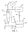
- Fig. 3 illustrates the fuel cell efficiency by the function curve of fuel cell power versus current density (in mA / cm 2 ).
- Fig. 3 shows the efficiency in a fuel cell that is fed with a single methanol solution at 90 ° and an air mixture pressure of 1.37 bar (20 PSIG). The curve shows that approximately 0.48 volts can be maintained at approximately 400 mA / cm 2 by means of the fuel cell.
- the optimization of the fuel cell requires a comparison between current density and cell efficiency.
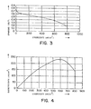
- 4 shows the power density as a function of the current density.
- the optimal operating point achieves a power density of approximately 230 mW / cm 2 .
- the optimal operating point occurs at current densities between 400 and 700 mA / cm 2 .
- the cell voltage within this range is between 0.48 and 0.31 volts. 5 shows the transient response or the transition function of the fuel cell.
- the settling time of the fuel cell is around 500-800 ms. This short settling time is suitable for use in arc welding torches, so that larger energy storage elements are not required.
- V 15 + 0.05I.
- Due to the losses in Energy conversion circuit and in the cables and due to the Compensating the welding load is a margin of safety provided by a few volts.
- the safety margin is based on experience under typical welding conditions and depends more or less on the current circumstances from.
- the cross-sectional area of the fuel cell is about the desired Load current and the operating current density of the cell are determined.
- Fig. 6 shows a welding circuit which has a power compensation converter (buck power converter).
- the table below shows the associated data for cell stack configurations when a compensation converter is used with common weld charges and operating conditions.
- the following operating conditions for the fuel cell were assumed: 220 mW / cm 2 and 500 mA / cm 2 (0.44 volts).
- the positive poles of the cell stack 110 are arranged on the side on which the oxidant is supplied and are connected to the input of the power converter circuit 200.
- the minus connection is on the side where fuel is supplied and is connected to a clamp on the workpiece 30.
- Welding circuit 200 is regulated to regulate the welding current in response to a feedback signal proportional to the welding voltage, welding current, or both. Reversing the welding electrode and workpiece connections would reverse the welding load current. For CO 2 welding processes, a structure with direct current and negative electrode is often desired.
- the cell stack 110 generates an excessive amount of CO 2 for welding.
- the CO 2 can contain trace elements of water or methanol vapor, which must be removed before the gas is fed into the arc welding torch.
- a gas dryer can be used to ensure that the gas is free of vapor contaminants.
- the fuel cell is operated at pressures which exceed ambient pressure, so that compression of the CO 2 is generally not necessary. However, if the operating pressure of the fuel cell is too low, the CO 2 gas can be compressed before it is fed to the welding arc.
- the flow rate of the shielding gas must be regulated to an appropriate level to avoid excessive arc disturbances. Since the fuel cell produces more CO 2 than is required to protect the arc, a flow regulator can be provided so that only a suitable amount of shielding gas flows. The rest of the CO 2 is suctioned off or used for other purposes.
- Fig. 6 shows the electrical connection in one configuration with direct current and positive electrode.
- a power converter circuit is used to output the fuel cell to match the welding load. 6 shows for this Purpose a compensation converter (chopper).
- the welding circuit 200 has a transistor 210, which by means of a Welding control system 220 is controlled.
- the welding control system controls the waveform of the welder supplied current.
- the welding control system can turn on feedback monitoring during the operation of the arc welding torch support.
- the welding circuit also has a diode 230 on to an appropriate current flow through the Maintain electrode through.
- the welding circuit an inductor around the one flowing through the electrode Smooth welding current waveform.
- the cell stack performance should always exceed the balancing load requirements, so that the compensation converter works effectively.
- FIG. 7 shows the topology of an additional voltage compensation converter.
- the additional voltage compensation circuit in the welding circuit 200 is constructed in such a way that the voltage at the electrode is increased without the number of fuel cells in the cell stack 110 having to be increased.
- Welding circuit 200 includes a welding control system 220 that is similar to the control system of FIG. 6.
- the welding circuit further includes an inductor 250, a capacitor 260 and a transistor 270 which is controlled by the welding control system 220 to boost the voltage through the welding circuit.
- the function of diodes 280, 290, transistor 300 and inductor 310 which operate similarly to the chopper or compensation circuit in Fig.
- FIGS. 8 and 9 schematically show control circuits for TIG welding torches.
- TIG welding When welding aluminum and similar metals TIG welding is used, whereby a non-melting Electrode such as a tungsten electrode in sufficient Distance from the workpiece is kept to an arc to get when due to an applied across the gap Voltage a current flows. Since aluminum oxidizes very quickly, it is necessary to remove the aluminum oxides from the welding surface to remove while the arc heat melts flux cored wire and deposited on the aluminum workpiece. The metal is going through Apply an AC power supply to straighten one AC current through the gap or gap between the electrode and workpiece cleaned. During a positive cycle the electrode is positive with respect to the workpiece; consequently will Electrons are emitted from the workpiece.
- This process solves and removes aluminum oxides from the surface in preparation for the immediately following negative cycle, the tungsten or other non-melting electrons negative relative to Workpiece. Electrons are taken in by the tungsten electrode Emitted towards the workpiece in order to be comparatively effective in the Arc area to be heated. By using AC over the arc become main cleaning cycles and generated heating cycles, making it a fairly efficient one TIG welding process for aluminum is created.
- the welder When using DC power sources in TIG welding the welder must select the polarity to be used. If unalloyed or stainless steel is to be welded, it does not have to be cleaned, so that DC TIG welding can be used with a negative electrode. That polarity does not provide an arc cleaning effect removing an oxide layer; if this system for aluminum welding cleaning and removal must be used as welding preparation the oxide layer on the welding surface become. However, this is only useful if heavy aluminum plates TIG-welded and the additional pre-cleaning work due to the increased welding speed when used the electrode with negative polarity. Because of this, the welder often chooses TIG welding with direct current and positive electrode, whereby then Current flows from the electrode to the workpiece. This causes in Combination with the arc welding process a cleaning effect.
- the modified direct current is then one Switching network 310 supplied.
- the switching network 310 converts the direct current into alternating current for use in one TIG welding device around.
- a wave profile 320 controls this Switch in the switching network to the duration of the positive and to control negative pulses during the welding cycle.
- a pulse width adjuster 330 represents the pulse duration of positive and / or negative Pulse on.
- Fig. 11 shows a polarity reversal circuit 340, the one from fuel cell 100 to arc welding torch 20 flowing direct current reverses. Switching the polarity can be controlled by software.
- the welding circuit is capable of a normal DC fuel cell for use with a TIG welding device convert to an AC power source.
- the Welding can also be done with melting welding electrodes be performed.
- the melting electrode is melted and on the workpiece by means of spherical transmission, Short circuit transmission, pulse current transmission etc. filed.
- the welding circuit can be used to generate a short-term reversal of current polarity can be used, which Welding as used in TIG welding.
- the welding circuit has the advantages of a normal AC TIG welding device with the additional performance, the extent of heating and cleaning the workpiece to be able to set for a short period.
- the welding circuit can regulate the ratio of plus to negative power, the amount of cleaning performed during positive current flow to control.
- the welding circuit can also be used to reduce arcing be used. Welding with melting Usually brings electrodes at high DC levels Arc warping with it due to magnetic field interactions caused by the arc plasma.
- the welding circuit can affect the effect of arcing Reduce short-term reversal of the arc current.
- the 10 is a fuel cell 100 as an energy supply shown for an STT welding torch type.
- the direct current of the Fuel cell provides power to the DC / DC circuit 300.
- the DC / DC circuit can be constructed as described in FIGS. 8 and 9 his.
- the current from the DC / DC circuit goes to the switching network 310.
- the switching network forms the desired waveform for the current on the workpiece 30.
- the switching network is controlled by a pulse width modulator (PWM) 340 that is controlled by means of an oscillator (OSC) 350.
- PWM pulse width modulator
- OSC oscillator
- the desired one Waveform for the current on the workpiece 30 is by means of the STT waveform profile 360 set.
- a background current setting device 370 and a maximum current setting device 380 are used to modify the waveform profile.
- the welding circuit can change the polarity of the waveform during a single Welding cycle or during different welding cycles Control using the polarity reversal circuit of FIG. 11.
- the electrode changes between a short-circuit condition, when the electrode touches the workpiece, and a Arc condition in which the electrode is spaced from the workpiece is back and forth.
- a electrical arc between the workpiece and the electrode for melting and maintaining the molten electrode end generated while this is for a subsequent short circuit condition is fed to the workpiece.
- the welding cycle alternates between short circuit and plasma state.
- the pulse width modulator operates at high frequencies.
- the operating frequency of the pulse width modulator is approximately 10-30 kHz, the width of the subsequent current pulse over the voltage at the waveform controller is determined. Since the Maximum welding cycle rate generally in the range of 100-400 Cycles per second are numerous updated Pulse generated during each welding cycle.
- the welding cycle directs electricity to the work area depending from operating the pulse width modulator controller until the functions dr / dt (where r is the electron resistance), di / dt or dv / dt an impending burnout during the pinch cycle Show. As soon as this is detected, the Welding circuit between the electrode and the workpiece caused current flow immediately reduced to a lower level.
- the background current circuit continues to apply a current of 5-7 A regardless of the operating condition of the welding circuit on.
- the background current ensures that a Current of at least 5-7 A at any time during the welding cycle flows between the electrode and the workpiece, causing a Extinguishing the arc between the electrode and the workpiece is prevented during each phase of the welding cycle.
- the electrode 60 is preferably a melting one Soul electrode, which has an outer metal shell and a Has electrode core. It is understood that alternatively the Electrode coated or could be a solid wire.
- the metal one Electrode sheath is preferably made of carbon steel, stainless steel or other metal or metal alloy.
- the composition of the metal shell is preferably such chosen to be similar to the metal composition of the Workpiece.
- the electrode core preferably has flux additives and / or alloys and metals.
- the flux can contain ingredients to create a slag over the weld pool to protect the weld pool until it hardens, to hold the weld pool in position until it hardens and / or around the weld metal during the formation of the weld pool shield.
- the flux can also contain components form the shielding gas to prejudice the root bed Protect environmental impacts.
- the alloy additives are preferred enclosed in the electrode core.
- the alloy additives are preferably chosen such that the alloy additives in coordination with the composition of the metal electrode sleeve form a weld pool that has a composition that is similar to the metal composition of the workpiece.
- Fig. 10 shows a desired current profile to minimize splashing during welding.
- This welding profile is in a pinch section, a plasma amplification section, a Plasma section and a background section divided, wherein the arc is maintained.
- the plasma amplification section which is the critical area in the operation of the control system against splashes is the constant here Current section before the decay section; the decay section can however also the end of the plasma amplification section or be assigned to the beginning of the plasma section.
- the current control circuit changes to the decay section the background current level, which is the plasma or arc maintains.
- the current control circuit holds a preselected one according to the invention Background current level up, which prevents the current level at the arc at some point below the selected one Low current level could drop at which the arc extinguish would.
- the current control circuit is designed so that it does everything Melting of the electrode during the plasma amplification - and plasma portion of the welding cycle. Another meltdown the electrode does not find on background current level instead of the resistance current required to melt the electrode with the arc only by means of background current maintaining current level is not available stands. The background current is therefore only used to maintain of the arc and the drop of molten metal in the melt state.
- the amount of molten metal on Electrode end by the plasma amplification and the plasma is formed is chosen such that it has a predetermined volume melts from molten metal at the electrode end, and the plasma portion of the stream is lowered to background current, once the predetermined volume is obtained. The duration the plasma amplification and plasma section can also be selected become.
- the molten metal from the weld pool until the desired amount of molten metal from Electrode end was melted.
- the one at the end of the electrode desired amount of molten metal is through Establishing a preselected amount of energy or wattage during the plasma portion of the welding cycle into the electrode controlled into it.
- the melting ball is Shielding gas shielded from the atmosphere.
- the inert gas inflow will continue until the melted ball into the molten metal was transferred into it. As soon as the molten metal ball and plasma portion of the welding cycle the molten ball is pushed forward by the electrode drawn into the weld pool, causing a short circuit condition is formed. When the melted metal ball is the melted one Metal bath is reached, it is caused by surface tension pulled into the bathroom. This results in the very last constriction that extending between the bath and the electrode wire molten metal, and then occurs Demolition and separation of the ball from the wire. There during there is only a low background current in the separation, little splashing may occur.
- the Current control circuitry pinching the molten metal ball such that the current flow during the pinch curve is stronger increases when the constriction changes extremely quickly in diameter reduced through electrical holes until an impending Breakthrough is detected. Once the detection of an impending Breakdown occurs, the current is at the background current level lowered until the molten metal at the electrode end passes into the weld pool.
- the current can be positive at any time, at any time negative or a combination of positive and negative Be pulsing.
- the Number of current cycles of positive polarity and negative polarity controlled to the desired heating in the melted Obtain metal puddle of the welding process. If the puddle is too is cold, the number of cycles becomes 320 with negative polarity increased relative to the number of cycles of positive current.
- the desired ratio is determined by a suitable selection circuit received in the welding controller.
- An alternative control concept can also be used, where every welding cycle starts with a standard cycle is negative polarity, which subsequently becomes a predetermined one Time in the cycle switched to a cycle with positive polarity becomes.
- the polarity of the quickly generated current pulse are switched after the plasma amplification section has ended. This will Final flank section into a negative section and a positive section divided with sudden polarity reversal. in the Connection, the current cycle has a positive polarity to the end of the cycle. In this way, the sweat puddle heat is through Selection of the time delay of polarity reversal during the welding cycle certainly.
- To control at an STT welding device the heat in the welding process between a positive polarity and switch a negative polarity of the current pulses back and forth, further modifications could be made.
Abstract
Description
Die Erfindung betrifft das elektrische Lichtbogenschweißen und insbesondere eine Lichtbogenschweißvorrichtung, die mittels einer brennstoffbetriebenen und transportablen Energiequelle mit Energie versorgt wird.The invention relates to electric arc welding and in particular an arc welding device, which by means of a fuel-powered and portable energy source Energy is supplied.
Die Patente US 4,861,965, US 4,972,064, US 5,148,001 und US 5,961,863 beschreiben beispielhaft Schweißvorrichtungen, die mit der erfindungsgemäßen Ausgestaltung einer transportablen Energiequelle verwendet werden können. Die bekannten Lichtbogenschweißvorrichtungen werden gewöhnlich dadurch mit Energie versorgt, daß sie an das Stromnetz angeschlossen werden oder mit einem gasbetriebenen elektrischen Generator ausgestattet werden. Schweißvorrichtungen, die an das elektrische Stromnetz angeschlossen werden sollen, können nur dort eingesetzt werden, an denen eine Anschlußnetzdose zur Verfügung steht, wobei die Anschlußnetzdose bzw. das Stromnetz derart bemessen sein muß, daß der zum Betreiben des Schweißbrenners benötige Strom geliefert wird. Die Mobilität einer an das Stromnetz angeschlossenen Lichtbogenschweißvorrichtung kann nur dadurch erhöht werden, daß die Schweißperson Verlängerungskabel zwischen Schweißvorrichtung und Netzanschluß einsetzt. Falls die Lichtbogenschweißvorrichtung ferngesteuert und/oder an Orten betrieben werden soll, die über keinen Stromanschluß bzw. über keine die benötigte Stromstärke aufweisenden Stromanschluß verfügen, betrieben werden soll, muß die Lichtbogenschweißvorrichtung mit ihrer eigenen Energiequelle wie z.B. einem elektrischen Gasgenerator ausgestattet werden, um den benötigten Strom für die Lichtbogenschweißvorrichtung zu erzeugen. Die eingesetzten Gasgeneratoren werden in der Regel mittels Mineralölbrennstoff wie Benzin betrieben. Unter zahlreichen Betriebsbedingungen reichen derartige mit zwei Energiequellen für die Lichtbogenschweißvorrichtung versehene Anordnungen aus, die Leistungsanforderungen für das Lichtbogenschweißvorrichtung zu erfüllen.Patents US 4,861,965, US 4,972,064, US 5,148,001 and US 5,961,863 describe exemplary welding devices with the inventive design of a portable energy source can be used. The known arc welding devices are usually powered by that they are connected to the mains or with a gas powered electric generator. Welding devices connected to the electrical network can only be used there which a mains socket is available, the mains socket or the power grid must be such that the electricity required to operate the welding torch becomes. The mobility of one connected to the power grid Arc welding device can only be increased in that the welding person extension cable between welding device and network connection. If the arc welding device to be remotely controlled and / or operated in locations that no power connection or none of the required amperage having power connection, operated , the arc welding device must use its own Energy source such as equipped with an electric gas generator to the required current for the arc welding device to create. The gas generators used are usually operated using mineral oil fuel such as petrol. These are sufficient under numerous operating conditions with two energy sources for the arc welding device provided orders, the performance requirements for the Arc welding device to meet.
Lichtbogenschweißvorrichtungen, die in abgelegenen Orten, insbesondere in teilweise oder vollständig geschlossenen oder nicht durchlüfteten Orten eingesetzt werden sollen, erfordern eine spezielle Ausstattung für den Schweißbetrieb. In derartigen Orten wird zur Energieversorgung für die Schweißvorrichtung ein gasbetriebener elektrischer Generator verwendet. Während des Betriebs des gasbetriebenen Generators werden Abgase erzeugt, die beim Einatmen zu Gesundheitsschäden führen können. Außerdem erzeugen die gasbetriebenen Generatoren Lärm beim Betrieb. Dieser Lärm kann zu temporärem Gehörverlust führen, insbesondere wenn die Lichtbogenschweißvorrichtung in kleinen, geschlossenen Räumen über längere Zeit eingesetzt wird. Neben den gesundheitsschädlichen Wirkungen für den Schweißer erzeugt der Betrieb eines gasbetriebenen Elektrogenerators Verschmutzungen, die nachteilig und/oder schädlich für die Umwelt sind. Die Verschmutzung betrifft sowohl Lärm als auch Abgasprodukte aus der Verbrennung des Brennstoffs beim gasbetriebenen Generator. Einflüsse auf die Luftverschmutzung bestehen auch bei elektrisch betriebenen Lichtbogenschweißbrennern, da für diese die elektrische Energie meist mittels Kohle- oder Atomkraftwerken erzeugt wird, die jeweils die ihnen eigenen Umweltrisiken bergen. Zusätzlich zu den Bedenken hinsichtlich der Luftverschmutzung der Energiequellen steigen auch deren Erzeugungskosten zunehmend. Da sich die Öl- und Kohlevorräte weltweit vermindern, werden die Kosten für Benzin und für durch Kohleverfeuerungsgeneratoren erzeugte Elektrizität unvermindert ansteigen. Steigende Energiekosten verlangsamen bzw. hemmen Wachstum in der Industrie.Arc welding devices used in remote locations, in particular in partially or completely closed or not ventilated places to be used require a special equipment for welding operations. In such places becomes a power supply for the welding device gas powered electric generator used. During operation of the gas powered generator, exhaust gases are generated which may cause health damage if inhaled. Generate also the gas powered generators noise during operation. This Noise can cause temporary hearing loss, especially if the arc welding device in small, closed rooms is used for a long time. In addition to the harmful The operation of a produces effects for the welder gas powered electrical pollution that is detrimental and / or are harmful to the environment. Pollution affects both noise and exhaust products from combustion of fuel at the gas powered generator. Influences on the Air pollution also exists in electrically operated Arc welding torches, because for them the electrical energy mostly generated by coal or nuclear power plants, each that carry their own environmental risks. In addition to the Concerns about air pollution from energy sources their production costs are also increasing. Since the oil and reduce coal reserves worldwide, the cost of gasoline and for electricity generated by coal-burning generators rise unabated. Slow rising energy costs or inhibit growth in industry.
Obwohl die vorgenannten Probleme seit geraumer Zeit existieren, wurden bis heute keine durchsetzungsfähigen Alternativen zu gasbetriebenen elektrischen Generatoren für Lichtbogenschweißvorrichtungen oder zu solchen, die an ein elektrisches Netz angeschlossen werden, vorgeschlagen. Batteriebetriebene Lichtbogenschweißvorrichtungen sind extrem unhandlich und haben eine begrenzte Lebenszeit. Außerdem muß die Batterie, nachdem sie entladen wurde, entsorgt werden, so daß die Batterie selbst eine Umweltbelastung darstellt. Zusätzlich benötigen viele Batterien konzentrierte Säuren, die gesundheitsschädlich sind, falls Säuredämpfe eingeatmet werden oder falls die Säure in Kontakt mit menschlicher Haut gelangt. Schließlich stellt die Säure auch eine Umweltbelastung dar, die eine spezielle und kostenintensive Entsorgung erfordert. Solarenergie ist eine weitere Energiequelle, jedoch ist deren Einsatz bei elektrischen Lichtbogenschweißvorrichtungen bisher nicht verwirklichbar. Die Solarkollektorengröße, die notwendig wäre, um die benötigte Energiemenge zu erzeugen, ist zu groß, insbesondere für den Einsatz in begrenzten Einsatzorten. Außerdem brauchen die Solarkollektoren Sonnenlicht, so daß die Solarbatterien an bewölkten Tagen oder in geschlossenen Räumen die notwendige elektrische Energie nicht erzeugen werden. Auch die hohen Kosten der Solarkollektoren verhindern aus Kostengründen deren Einsatz bei Lichtbogenschweißvorrichtungen. Auch windbetriebene Generatoren sind aufgrund ihrer sperrigen Konstruktion und ihrem zwingenden Bedarf für eine kontinuierliche Windquelle ungeeignet. Die Unhandlichkeit der Batterien, Solarkollektoren und windbetriebenen Generatoren vereinigen in sich die spezifischen, bestehenden Größenprobleme bei Lichtbogenschweißvorrichtungen. Der elektrische Schaltungsaufbau in der Schweißvorrichtung ist aufgrund der Leistungsanforderungen von Lichtbogenschweißvorrichtungen auf eine bestimmte Größe begrenzt. Lichtbogenschweißbrenner, die Schutzgas benötigen, umfassen sperrige Kanister für die Schutzgasversorgung. Die Kombination sperriger Schutzgaskanister mit einer sperrigen Energiequelle würde die Lichtbogenschweißvorrichtung zu unhandlich für den Einsatz in zahlreichen Einsatzorten machen.Although the aforementioned problems have existed for some time, To date, there have been no assertive alternatives to gas-powered ones electric generators for arc welding devices or to those connected to an electrical network are proposed. Battery operated arc welding devices are extremely bulky and have a limited amount Lifetime. The battery must also be discharged after it was disposed of, so that the battery itself a Represents environmental pollution. In addition, many batteries are required concentrated acids that are harmful to health if acid vapors be inhaled or if the acid comes in contact with human skin. After all, the acid also makes one Environmental pollution, which is a special and costly Disposal required. Solar energy is another source of energy however, their use is in electric arc welding devices so far not feasible. The solar collector size, that would be necessary to generate the required amount of energy, is too big, especially for use in limited Locations. In addition, the solar panels need sunlight, so that the solar batteries on cloudy days or in closed Rooms do not generate the necessary electrical energy become. Also prevent the high cost of solar collectors for cost reasons, their use in arc welding devices. Also wind powered generators are due to their bulky construction and its imperative need for one continuous wind source unsuitable. The unwieldiness of Combine batteries, solar collectors and wind powered generators the specific, existing size problems Arc welding devices. The electrical circuit construction in the welding device is due to the performance requirements of arc welding devices to a certain size limited. Arc welding torches that require shielding gas bulky canisters for inert gas supply. The combination bulky inert gas canister with a bulky energy source the arc welding device would be too unwieldy for use in numerous locations.
Angesicht der mit alternativen Energiequellen für elektrische Lichtbogenschweißvorrichtungen verbundenen Probleme besteht ein Bedarf für eine verbesserte Energiequelle, die umweltfreundlich, einfach aufgebaut und sicher zu betreiben ist, und die unter zahlreichen Einsatzbedingungen eingesetzt werden kann. Given that using alternative energy sources for electrical There are problems associated with arc welding devices Need for an improved energy source that is environmentally friendly, is easy to set up and operate safely, and that under numerous operating conditions can be used.
Zusammengefaßt betrifft die Erfindung ein Verfahren und eine Vorrichtung zum Zusammenschweißen von Metallplatten durch Lichtbogenschweißen. Hauptaufgabe der Erfindung ist es, ein Lichtbogenschweißsystem und -verfahren zu schaffen, das eine hochqualitative Schweißraupe zwischen zwei Metallplatten ausbildet. Das Lichtbogenschweißsystem und -verfahren soll hierbei umweltfreundlich sein, und im Betrieb die Geräuschbelastung und Umweltverschmutzung reduzieren. Außerdem soll das Lichtbogenschweißsystem und -verfahren unter zahlreichen Einsatzbedingungen verwendet werden können und transportabel sein.In summary, the invention relates to a method and a Device for welding metal plates together by arc welding. The main object of the invention is an arc welding system and procedures to create a high quality Welding bead forms between two metal plates. The Arc welding system and process is intended to be environmentally friendly be, and in operation the noise and pollution to reduce. In addition, the arc welding system and processes under numerous operating conditions can be used and be portable.
Diese und weitere Aufgaben werden für die Lichtbogenschweißvorrichtung
durch die in Anspruch 1 angegebene Erfindung und für
das Verfahren durch die in Anspruch 27 angegebene Erfindung gelöst.These and other tasks are for the arc welding device
by the invention specified in
Erfindungsgemäß ist hierbei vorgesehen, daß die Lichtbogenschweißvorrichtung bzw. das -verfahren eine Brennstoffzelle als Energiequelle verwenden, mit der die Lichtbogenschweißvorrichtung vollständig oder teilweise mit Energie versorgt wird.According to the invention, it is provided that the arc welding device or the process a fuel cell as Use energy source with which the arc welding device fully or partially supplied with energy.
Mit Brennstoffzellen im allgemeinen beschäftigen sich beispielsweise die Patente US 5,509,638, US 5,656,388, US 5,773,162, US 5,795,496, US 5,888,665, US 5,928,806 sowie die PCT-Anmeldungen W098/22989, W098/45694, W099/16137 und W099/39841. Der Offenbarungsgehalt dieser Patente bzw. Patentanmeldungen wird in die vorliegende Anmeldung eingeschlossen, um die Herstellung der Brennstoffzellenkomponenten und den Betrieb von Brennstoffzellen im einzelnen zu beschreiben.For example, deal with fuel cells in general the patents US 5,509,638, US 5,656,388, US 5,773,162, US 5,795,496, US 5,888,665, US 5,928,806 and PCT applications W098 / 22989, W098 / 45694, W099 / 16137 and W099 / 39841. The revelation content of these patents or patent applications is in the present application included to the manufacture of the Fuel cell components and the operation of fuel cells to describe in detail.
Gemäß einer bevorzugten erfindungsgemäßen Ausführungsform wird eine Brennstoffzellen-Energiequelle mit einem Pluspol und einem Minuspol und einem Schweißstromschaltkreis geschaffen, mit dem ein Schweißstrom zwischen Schweißelektrode und Werkstück angelegt werden kann. Die Brennstoffzelle ist eine elektrochemische Zelle, in der die aus einem Brennstoffoxidationsprozeß resultierende freie (chemische) Energie in elektrische Energie umgewandelt wird. Bei einer Ausführungsform handelt es sich um eine Organische/Luft-Brennstoffzelle, die an der Anode organischen Brennstoff zu Kohlendioxyd oxidiert, während an der Kathode Luft oder Sauerstoff zu Wasser reagieren (Reduktion). Brennstoffzellen, die organische Brennstoffe verwenden, sind wegen der hohen spezifischen Energie der organischen Brennstoffe äußerst attraktiv. Bei den Brennstoffzellen kann es sich hierbei um eine "indirekte" oder "Reformer"-Brennstoffzelle oder um eine "Direktoxidations"-Brennstoffzelle handeln. Bei einer indirekten Brennstoffzelle wird der Brennstoff katalytisch reformiert und weiterverarbeitet. Bei organischen Brennstoffen wird der Brennstoff katalytisch reformiert und in kohlenmonoxydfreien Wasserstoff umgewandelt, wobei der derart erhaltene Wasserstoff an der Anode der Brennstoffzelle oxidiert. Bei der Brennstoffzelle mit direkter Oxidation wird der Brennstoff ohne vorherige chemische Modifikationen direkt in die Brennstoffzelle eingespeist, in der der Brennstoff dann an der Anode oxidiert. Brennstoffzellen mit direkter Oxidation erfordern keine Brennstoffvorbehandlungsstufe. Insgesamt sind Brennstoffzellen mit direkter Oxidation weniger kompliziert aufgebaut und bauen kleiner als indirekte Brennstoffzellen.According to a preferred embodiment of the invention a fuel cell energy source with a positive pole and one Negative pole and a welding current circuit created with which a welding current is applied between the welding electrode and the workpiece can be. The fuel cell is an electrochemical one Cell in which the resulting from a fuel oxidation process free (chemical) energy converted into electrical energy becomes. In one embodiment, it is an organic / air fuel cell, the organic ones at the anode Fuel oxidizes to carbon dioxide while air is at the cathode or react oxygen to water (reduction). Fuel cells, who use organic fuels are because of the high specific energy of organic fuels extremely attractive. The fuel cells can be an "indirect" or "reformer" fuel cell or a "direct oxidation" fuel cell act. With an indirect fuel cell the fuel is catalytically reformed and processed. With organic fuels, the fuel catalytically reformed and in carbon monoxide-free hydrogen converted, the hydrogen thus obtained at the anode the fuel cell oxidizes. With the fuel cell with direct Oxidation becomes the fuel without any previous chemical modifications fed directly into the fuel cell in which the Fuel then oxidizes at the anode. Direct fuel cells Oxidation does not require a fuel pre-treatment step. Overall, direct oxidation fuel cells are fewer complex and smaller than indirect fuel cells.
Gemäß einem weiteren Erfindungsaspekt weisen die Brennstoffzellen Anoden und/oder Kathoden mit elektrokatalytischen Hartmantelflächen auf(high-surface-area electro-catalytic anodes or cathodes). Bei einer Ausgestaltung umfaßt die Anoden- und/oder Kathodenherstellung das Vorsehen einer Hartmantelfläche mit Metallstaub auf einer Unterschicht auf Kohlenstoffbasis. Hierzu kann Legierungsstaub zusammen mit einem TEFLON-Bindemittel auf eine Kohlenstofffaserverstärkte Unterlage aufgebracht werden, um eine Gasdiffusions-Anode und/oder -Kathode zu erzielen. Die Anode und/oder Kathode kann auch für gasförmige und/oder flüssige Versorgungsmaterialien eingesetzt werden. Weiter vorzugsweise kann die Anode und/oder Kathode stark porös sein, um eine saubere Benetzung der Poren zu erlauben.According to a further aspect of the invention, the fuel cells Anodes and / or cathodes with electrocatalytic hard-shell surfaces on (high-surface-area electro-catalytic anodes or cathodes). In one embodiment, the anode and / or cathode manufacture comprises the provision of a hard surface with metal dust on a carbon-based underlayer. For this can apply alloy dust together with a TEFLON binder a carbon fiber reinforced backing can be applied to to achieve a gas diffusion anode and / or cathode. The anode and / or cathode can also be used for gaseous and / or liquid Supplies are used. More preferably the anode and / or cathode can be highly porous to ensure a clean To allow wetting of the pores.
Gemäß einer weiteren erfindungsgemäßen Ausgestaltung können die Anode und/oder Kathode der Brennstoffzelle mit einer Substanz beschichtet sein, die die Benetzungseigenschaften der Elektrode verbessern. Im Zusammenhang mit diesem besonderen erfindungsgemäßen Aspekt können die Anode und/oder Kathode mit einem perfluorinierte Sulfonsäure aufweisenden Material beschichtet sein, um die Benetzungseigenschaften der Anode und/oder Kathode zu steigern. Die Beschichtung senkt die Grenzflächenspannung an der Grenzfläche zwischen Flüssigkeit und Katalysator und führt zu einer gleichmäßigeren Benetzung der Anoden- und/oder Kathodenporen und -partikel durch das flüssige Brennstoffgemisch, wodurch eine verbesserte Ausnutzung des Elektrokatalysators hervorgerufen wird. Die Beschichtung sorgt auch für den Ionendurchgang an der Feststoff-Elektrolytmembran und erlaubt einen effizienten Transport der durch den Brennstoff-Oxidationsprozeß erzeugten Protonen oder Hydronium-Ionen. Die Beschichtung kann ferner die Freisetzung von Kohlendioxyd an den Poren der Anode und/oder Kathode erleichtern. Durch Verwenden einer perfluorinierten Sulfonsäure werden Anionengruppen nicht allzu stark an der Anodenund/oder Kathoden-Elektrolytengrenzfläche absorbiert. Die Kinetik der Elektrooxidation des Methanol ist folglich leichter möglich als bei Schwefelsäure-Elektrolyten. Weitere hydrophile, protonleitende Zusätze mit den gewünschten Eigenschaften, die alternativ oder in Kombination mit perfluorinierter Sulfonsäure eingesetzt werden können, umfassen Montmorillonit, verätherte Zellulose (Alkoxycelluloses), Cyclodextrin, Mischungen aus Zeolith und/oder Zirkoniumwasserstoffphosphate.According to a further embodiment according to the invention, the Anode and / or cathode of the fuel cell with a substance be coated, the wetting properties of the electrode improve. In connection with this particular invention Aspect can be the anode and / or cathode with a perfluorinated Material containing sulfonic acid to be coated to increase the wetting properties of the anode and / or cathode. The coating lowers the interfacial tension on the Interface between liquid and catalyst and leads to a more uniform wetting of the anode and / or cathode pores and particles through the liquid fuel mixture, whereby improved use of the electrocatalyst becomes. The coating also ensures the passage of ions the solid electrolyte membrane and allows an efficient Transport of those generated by the fuel oxidation process Protons or hydronium ions. The coating can also Release of carbon dioxide at the pores of the anode and / or cathode facilitate. By using a perfluorinated sulfonic acid anion groups are not too strong on the anode and / or Cathode-electrolyte interface absorbed. The kinetics the electrooxidation of the methanol is consequently easier than with sulfuric acid electrolytes. More hydrophilic, proton-conducting additives with the desired properties, the alternatively or in combination with perfluorinated sulfonic acid can be used include montmorillonite, etherified Cellulose (alkoxy celluloses), cyclodextrin, mixtures of zeolite and / or zirconium hydrogen phosphates.
Gemäß einem weiteren Erfindungsaspekt kann in der Brennstoffzelle ein flüssiger Brennstoff verwendet werden. Bei einer Ausgestaltung erfährt der flüssige Brennstoff innerhalb der Brennstoffzelle eine saubere und effiziente elektrochemische Oxidation. Für direkt oxidierende Brennstoffzellen wird die effiziente Ausnutzung der organischen Brennstoffe durch die Leichtigkeit beherrscht, mit der die organischen Bestandteile anodisch innerhalb der Brennstoffzelle oxidiert werden. Der organische Brennstoff kann insbesondere aus Methanol, Formaldehyd, Formylsäure, Trimethoxymethan, Dimethoxymethan und/oder Trioxan bestehen. According to a further aspect of the invention, the fuel cell a liquid fuel can be used. In one configuration experiences the liquid fuel inside the fuel cell a clean and efficient electrochemical oxidation. For direct oxidizing fuel cells, the efficient one Utilization of organic fuels through lightness with which the organic components are anodized within the fuel cell are oxidized. The organic fuel can in particular from methanol, formaldehyde, formyl acid, Trimethoxymethane, dimethoxymethane and / or trioxane exist.
Bei der Brennstoffzelle kann es sich auch um eine direkte, flüssigkeitsgespeiste Brennstoffzelle handeln, die keinen Säureelektrolyten benötigt. Ein Feststoff-Polymermembran-Elektrolyt kann eingesetzt werden, um auf den Säureelektrolyten verzichten zu können. Der feste Polymermembran-Elektrolyt kann zusammen mit einer batterieartigen Anode, die porös ist und zum Benetzen des Brennstoffs geeignet ist, eingesetzt werden. Ein batterieartiger Anodenaufbau und eine Kathode können auch mit beiden Seiten des Feststoff-Polymermembran-Elektrolyten verbunden sein. Ein Gemisch eines organischen Zuführmittels, das im wesentlichen säurefrei ist, wird an der Anodenseite der Anordnung vorbeigeführt. Die Feststoff-Polymermembran ist derart berechnet, daß sie ausgezeichnete elektrochemische und mechanische Stabilität und hohe Ionenleitfähigkeit hat und sowohl als Elektrolyt als auch als Separator fungiert. Außerdem wird die Kinetik der Elektrooxidation des organischen Zuführmittels und die Elektroreduktion von Luft oder Sauerstoff an der Grenzfläche zwischen Anoden und/oder Kathoden und Elektrolytenmembran stärker erleichtert als an der Grenzfläche zwischen Anoden bzw. Kathoden und Schwefelsäure, wenn ein organisches Zuführmittel wie Methanol eingesetzt wird. In weiterer Ausgestaltung handelt es sich bei dem festen Polymerelektrolyten um eine protonleitende, Kationen austauschende Membran. Bei dieser Ausgestaltung kann die Membran insbesondere Tetrafluorethylen, ein perfluoriniertes Sulfonsäurepolymer, eine Polysterensulfonsäure, ein Polyvinylfluorid, eine Polykohlenwasserstoff-Sulfonsäure und/oder ein Copolymer aus Tetrafluorethylen und Perfluorvinylether-Sulfonsäure umfassen. In weiterer Ausgestaltung können die einsetzbaren Membranen aus modifiziertem perfluoriniertem Sulfonsäure-Polymer oder Polykohlenwasserstoffsulfonsäure ein sulfoniertes Polyether-Ether-Keton und/oder ein Polyvinylen-Ethersulfon aufweisen. Ferner kann die Austauschmembran aus einem Verbund aus zwei oder mehr unterschiedlichen Protonenaustauschmembranen gebildet werden. Die Membran erlaubt vorzugsweise den Betrieb der Brennstoffzelle bei Temperaturen bis wenigstens 120°C. Ferner ist die Brennstoffzelle vorzugsweise im wesentlichen frei von teuren, rostbeständigen Bauteilen, da keine Säureelektrolyten vorhanden sind. Die Membrandicke liegt vorzugsweise zwischen 0,05 und 1 mm. The fuel cell can also be a direct, liquid-fed one Act fuel cells that do not contain acid electrolytes needed. A solid polymer membrane electrolyte can can be used to dispense with the acid electrolyte can. The solid polymer membrane electrolyte can coexist with a battery-like anode that is porous and for wetting the Suitable fuel is used. A battery-like Anode structure and a cathode can also be used with both sides of the Solid polymer membrane electrolytes. A mixture an organic feed agent that is substantially acid free is guided past the anode side of the arrangement. The solid polymer membrane is calculated to be excellent electrochemical and mechanical stability and high Has ionic conductivity and both as an electrolyte and as Separator acts. Also, the kinetics of electrooxidation of the organic feeder and the electroreduction of Air or oxygen at the anode and / or interface Cathode and electrolyte membrane easier than on the Interface between anodes or cathodes and sulfuric acid, when an organic feed agent such as methanol is used. In a further embodiment, the solid polymer electrolyte is concerned a proton-conducting, cation-exchanging Membrane. In this embodiment, the membrane can in particular Tetrafluoroethylene, a perfluorinated sulfonic acid polymer, a Polysterensulfonic acid, a polyvinyl fluoride, a polycarbon sulfonic acid and / or a copolymer of tetrafluoroethylene and perfluorovinyl ether sulfonic acid. In another Embodiment can use the modified membranes perfluorinated sulfonic acid polymer or polyhydrocarbon sulfonic acid a sulfonated polyether ether ketone and / or have a polyvinylene ether sulfone. Furthermore, the exchange membrane from a combination of two or more different ones Proton exchange membranes are formed. The membrane preferably allows the fuel cell to operate at temperatures up to at least 120 ° C. Furthermore, the fuel cell preferably essentially free of expensive, rust-resistant Components since there are no acid electrolytes. The membrane thickness is preferably between 0.05 and 1 mm.
Gemäß einer weiteren erfindungsgemäßen Ausgestaltung ist die Anode der Brennstoffzelle aus Hartmantelflächenpartikeln mit Legierungen auf Platin-Basis und mit edlen oder nichtedlen Metallen gebildet. Hierbei können binäre oder ternäre Zusammensetzungen für die Elektrooxidation des organischen Brennstoffs verwendet werden. Die Platinlegierung für die Anode kann Zusammensetzungen mit 10-90 % Platin enthalten. Die Platinlegierung kann Ruthenium, Zinn, Iridium, Osmium und/oder Rhenium enthalten. Das Platin oder Teile des Platins in der Platinlegierung können durch Paladium, Wolfram, Rhodium, Eisen, Kobalt, Titan, Iridium, Chrom, Mangan, Molybdän, Niob, Zirkonium, Osmium, Titanoxyd und/oder Nickel ersetzt sein. Alternativ können die Platinlegierungspartikel auch in Gestalt feinen Metallstaubs, d.h. "ununterstützt" und/oder auf einem Hartmantelflächenmaterial abgestützt sein. Das Hartmantelflächenmaterial kann hierbei ein Karbonmaterial umfassen. Die Platinlegierung kann der Elektrokatalysatorschicht im Bereich von etwa 0,05 - 4, 0 mg/cm2 zugesetzt sein. Ferner können der Platinlegierung Partikel aus Titanoxyd, Iridium und/oder Osmium zusetzt sein, um die Brennstoffzellenleistungsfähigkeit zu verbessern. Die gemittelte Durchschnittsgröße der Partikel an der Anode liegt bei etwa 0,5 - 8 µm.According to a further embodiment according to the invention, the anode of the fuel cell is formed from hard-shell surface particles with platinum-based alloys and with noble or non-noble metals. Binary or ternary compositions can be used for the electrooxidation of the organic fuel. The platinum alloy for the anode can contain 10-90% platinum compositions. The platinum alloy can contain ruthenium, tin, iridium, osmium and / or rhenium. The platinum or parts of the platinum in the platinum alloy can be replaced by palladium, tungsten, rhodium, iron, cobalt, titanium, iridium, chromium, manganese, molybdenum, niobium, zirconium, osmium, titanium oxide and / or nickel. Alternatively, the platinum alloy particles can also be supported in the form of fine metal dust, ie "unsupported" and / or on a hard-shell surface material. The hard shell surface material can comprise a carbon material. The platinum alloy can be added to the electrocatalyst layer in the range of approximately 0.05 - 4.0 mg / cm 2 . Titanium oxide, iridium and / or osmium particles can also be added to the platinum alloy to improve fuel cell performance. The average size of the particles at the anode is around 0.5 - 8 µm.
Gemäß einem weiteren Erfindungsaspekt ist die Kathode der Brennstoffzelle aus Partikeln gebildet, die Platin, auf Träger oder trägerlos, in der protonendurchlässigen Membran aufweisen. Die Platinpartikel können auf einem Trägermaterial, das Karbon enthält, aufgebracht sein. Die Kathode kann Materialien aufweisen, die die Hydrophobie der Kathode steigern. Das die Hydrophobie steigernde Material kann Tetrafluorethylen sein. Die Platinpartikel können der Elektrokatalysatorschicht im Bereich von etwa 0,05 - 4,0 mg/cm2 zugesetzt sein. Die Durchschnittsgröße der Partikel an der Kathode liegt bei etwa 0,5 - 8 µm.According to a further aspect of the invention, the cathode of the fuel cell is formed from particles which have platinum, supported or unsupported, in the proton-permeable membrane. The platinum particles can be applied to a carrier material that contains carbon. The cathode can have materials that increase the hydrophobicity of the cathode. The hydrophobicity increasing material can be tetrafluoroethylene. The platinum particles can be added to the electrocatalyst layer in the range from approximately 0.05 to 4.0 mg / cm 2 . The average size of the particles at the cathode is around 0.5 - 8 µm.
Gemäß einem weiteren erfindungsgemäßen Aspekt handelt es sich bei der Brennstoffzelle um eine regenerierende Brennstoffzelle. Die Brennstoffzelle kann Kohlendioxyd zu sauerstoffangereichertem Kohlenwasserstoff und Sauerstoff reduzieren. Die sauerstoffangereicherten Kohlenwasserstoffe können Methylalkohol, Methylformat, Formaldehyd und/oder Formylsäure aufweisen.According to a further aspect according to the invention in the fuel cell around a regenerating fuel cell. The fuel cell can convert carbon dioxide to oxygenated Reduce hydrocarbon and oxygen. The oxygenated Hydrocarbons can be methyl alcohol, methyl format, Have formaldehyde and / or formylic acid.
Gemäß einer weiteren erfindungsgemäßen Ausgestaltung werden eine Mehrzahl von Brennstoffzellen zu einem Zellenstapel (stack) zusammengefaßt, um die mittels der Brennstoffzellen erzeugte Spannung und/oder den erzeugten Strom zu steigern. Hierzu können eine Mehrzahl von Brennstoffzellen parallel geschaltet werden. Alternativ können eine Mehrzahl von Brennstoffzellen in Reihe geschaltet werden.According to a further embodiment according to the invention, a A plurality of fuel cells combined into a cell stack, the voltage generated by the fuel cells and / or to increase the electricity generated. For this, a A plurality of fuel cells are connected in parallel. Alternatively can connect a plurality of fuel cells in series become.
Gemäß einem weiteren erfindungsgemäßen Aspekt wird eines oder werden mehrere Reaktionsprodukte der Brennstoffzelle zumindest teilweise als Schutzgas für die Lichtbogenschweißvorrichtung verwendet. Das von der Brennstoffzelle erzeugte Schutzgas kann hierbei insbesondere Kohlendioxyd und/oder Kohlenmonoxyd umfassen. Ein Entfeuchter, ein Kondensor und/oder eine Reinigungseinrichtung werden eingesetzt, um unerwünschte Gase und/oder Flüssigkeiten aus dem gasförmigen Reaktionsprodukt zu entfernen, bevor dieses dem Schweißbad zugeführt wird. Ein Schutzgasregler kann eingesetzt werden, um die dem Werkstück zugeführte Schutzgasmenge zu regulieren und/oder den Druck des Schutzgases am Werkstück zu steuern.According to a further aspect of the invention, one or are at least several reaction products of the fuel cell partly as a protective gas for the arc welding device used. The protective gas generated by the fuel cell can include in particular carbon dioxide and / or carbon monoxide. A dehumidifier, a condenser and / or a cleaning device are used to remove unwanted gases and / or liquids remove from the gaseous reaction product before this is fed to the weld pool. An inert gas regulator can be used to control the amount of shielding gas supplied to the workpiece to regulate and / or the pressure of the protective gas on Control workpiece.
Bei der Schweißelektrode kann es sich um eine abschmelzende Elektrode handeln. Gemäß einer Ausführungsform kann die abschmelzende Elektrode eine Elektrode mit Flußmittelseele sein, die ein Flußsystem innerhalb des Elektrodenkerns aufweist, um während des Schweißprozesses für die Schutzgasversorgung und/oder die gewünschte Schlacke zu sorgen. Die abschmelzende Kernelektrode kann Metallegierungen im Kern aufweisen, um eine Schweißraupenzusammensetzung zu erhalten, die im wesentlichen ähnlich zu der Zusammensetzung der zusammengeschweißten Werkstücke ist. Eine Schweißraupe, die eine Zusammensetzung hat, die annähernd der Zusammensetzung der Werkstücke entspricht, bildet eine starke, strapazierfähige und hochqualitative Schweißverbindung aus. Alternativ kann es sich bei der abschmelzenden Elektrode auch um eine flußmittelbeschichtete Elektrode oder eine massive Metallelektrode handeln.The welding electrode can be a melting one Act electrode. According to one embodiment, the melting Electrode be an electrode with a flux core, which has a flow system within the electrode core to during the welding process for the protective gas supply and / or to provide the desired slag. The melting one Core electrode can have metal alloys in the core in order to To get welding bead composition that essentially similar to the composition of the welded workpieces is. A sweat bead that has a composition that corresponds approximately to the composition of the workpieces a strong, durable and high quality welded joint out. Alternatively, it can be the melting electrode also a flux-coated electrode or a act massive metal electrode.
Nach einem weiteren erfindungsgemäßen Aspekt ist der Schweißschaltkreis zum Einsatz in einer Kurzschlußlichtbogenschweißvorrichtung ausgelegt. Der Schweißschaltkreis kann eine erste Schaltung zum Steuern des Stromflusses während des Kurzschlußzustandes aufweisen, bei welchem geschmolzenes Metall am abschmelzenden Elektrodenkernende hauptsächlich mittels eines Übertragungsstroms durch einen Oberflächenspannungsvorgang in das aufgeschmolzene Metallbad übertragen wird. Der Übertragungsstrom kann hierbei einen Hochstrom-Pinchpuls quer zum kurzgeschlossenen geschmolzenen Material aufweisen, der den Übergang des geschmolzenen Materials von der Elektrode zum Schweißbad erleichtert. Der Schweißstromschaltkreis kann in weiterer Ausgestaltung eine zweite Schaltung umfassen, um einen Schmelzstrom zu erzeugen. In bevorzugter Ausgestaltung handelt es sich beim Schmelzstrom um einen Hochstrompuls, der durch den Lichtbogen geführt wird. Der Hochstrompuls hat eine vorbestimmte Energiemenge oder Menge an aufgenommener Leistung, die zum Schmelzen eines relativ konstanten Metallvolumens am abschmelzenden Elektrodenende verwendbar ist, wenn die Elektrode im Abstand vom Schweißbad gehalten wird. Bei einer anderen Ausgestaltung kann die zweite Schaltung des Schweißstromschaltkreises während des Anfangsabschnitts des Lichtbogenzustandes für eine hochenergetische Zusatzspannung (boost) sorgen. Der Hochstrom-Boost hat mit I (t) eine vorbestimmte Energiefläche zum Schmelzen eines vergleichsweise konstanten Metallvolumens am abschmelzenden Drahtende, wenn der Draht im Abstand vom Schweißbad ist. Die während der Hochstromzusatzspannung bzw. beim Plasma-Boost erzeugte Energie reicht aus, einen kugelförmigen Metallball zu schaffen, dessen Durchmesser kleiner als der doppelte Durchmesser des Schweißdrahtes ist. In weiterer Ausgestaltung kann, im Anschluß an den anfänglichen Hochstrom-Boost, ein Hochstrom für eine vorbestimmte Zeitperiode aufrechterhalten werden und dann nachfolgend reduziert werden, so daß der Elektrode die gewünschte Energie- oder Leistungsmenge zugeführt wird, um das gewünschte Elektrodenvolumen abzuschmelzen. In besonderer Ausgestaltung dieser Ausführungsform findet die Reduzierung des Hochstroms in Form eines um eine Zeitperiode verzögerten Stroms statt. Alternativ kann der Schweißstromschaltkreis die der Elektrode zugeführte Energiemenge begrenzen, um unerwünschtes Aufschmelzen am Elektrodenende bzw. an den Werkstückrändern zu verhindern.According to another aspect of the invention, the welding circuit is for use in a short-circuit arc welding device designed. The welding circuit can be a first Circuit for controlling the current flow during the short circuit condition have, in which molten metal at the melting end Electrode core end mainly by means of a transmission current through a surface tension process in the melted Metal bath is transferred. The transmission current can be a high current pinch pulse across the short-circuited have melted material which is the transition of the melted Material from the electrode to the weld pool relieved. The welding current circuit can in a further embodiment include a second circuit to generate a melt stream. In a preferred embodiment, the melt flow is involved around a high current pulse that led through the arc becomes. The high current pulse has a predetermined amount of energy or Amount of power consumed to melt a relative constant metal volume can be used at the melting end of the electrode is when the electrode is kept at a distance from the weld pool becomes. In another embodiment, the second circuit of the welding circuit during the initial section of the arcing condition for a high-energy additional voltage (boost) worry. The high current boost has a predetermined one at I (t) Energy area for melting a comparatively constant Metal volume at the melting wire end when the Wire is at a distance from the weld pool. The during the high current auxiliary voltage or energy generated during plasma boost is sufficient from creating a spherical metal ball whose diameter smaller than twice the diameter of the welding wire is. In a further embodiment, following the initial High current boost, a high current for a predetermined Time period are maintained and then subsequently reduced be so that the electrode the desired energy or Power quantity is supplied to the desired electrode volume to melt. In a special embodiment of this embodiment finds the reduction of high current in the form of a a period of delayed current takes place. Alternatively, the Welding current circuit the amount of energy supplied to the electrode limit to unwanted melting at the electrode end or to prevent at the workpiece edges.
In weiterer erfindungsgemäßer Ausgestaltung kann der Schweißstromschaltkreis eine Schaltung zum Erzeugen eines Hintergrundstroms aufweisen. Hierbei kann der Hintergrundstrom ein Niedrigstrom sein, der auf einem Niveau aufrechterhalten wird, das gerade oberhalb des zum Aufrechterhalten eines Lichtbogens nach Beendigung des Kurzschlußzustandes notwendigen Niveaus liegt. In weiterer Ausgestaltung kann der Hintergrundstrom während des gesamten Schweißzyklus aufrechterhalten bleiben, um sicherzustellen, daß der Lichtbogen während des Schweißens nicht unbeabsichtigt erlischt.In a further embodiment according to the invention, the welding current circuit can a circuit for generating a background current exhibit. Here, the background current can be a low current be maintained at a level that is just above that to maintain an arc Termination of the short-circuit state is necessary levels. In In a further embodiment, the background current can be used throughout Welding cycle maintained to ensure that the arc is not inadvertently during welding goes out.
Der Schweißschaltkreis kann gemäß einer weiteren erfindungsgemäßen Ausgestaltung eine Schalteinrichtung zum Umschalten von Polaritäten während des Schweißprozesses umfassen. In einer ersten Ausgestaltung können die Dauer der Pulse mit positiver und negativer Polarität während eines einzelnen Schweißzyklus gleich sein. Alternativ kann die Dauer des Pulses mit positiver bzw. negativer Polarität während eines einzelnen Schweißzyklus unterschiedlich sein. Hierbei kann ein Puls mit positiver Polarität während eines ersten Schweißzyklus und ein Puls mit negativer Polarität während eines anderen Schweißzykluses auftreten. Die Schalteinrichtung kann softwaremäßig gesteuert werden.The welding circuit can be according to another invention Embodiment a switching device for switching polarities during the welding process. In a first The duration of the pulses can be configured with positive and negative Polarity equal during a single welding cycle his. Alternatively, the duration of the pulse can be positive or negative polarity varies during a single welding cycle his. This can be a pulse with positive polarity during a first welding cycle and a pulse with negative Polarity may occur during another welding cycle. The Switching device can be controlled by software.
Gemäß einer weiteren bevorzugten erfindungsgemäßen Ausgestaltung wird eine STT-Schweißvorrichtung der Anmelderin (The Lincoln Electric Company) oder ein STT-Kurzschlußschweißprozeß eingesetzt. Der STT-Prozeß kann zusammen mit einer Kernelektrode eingesetzt werden. Alternativ kann beim STT-Prozeß eine abschweißende Elektrode verwendet werden und die Polarität an der Elektrode ist negativ. Beim Verwenden des Negativelektrodenprozesses beim STT-Schweißer ist der Werkstückpuddel heiß und das Kühlen des Puddels benötigt Zeit, die es erlaubt, die Schweißraupe zurückzuziehen. Gemäß einer erfindungsgemäßen Ausgestaltung kann der Hintergrundstrom reduziert werden, um die Hitze im Puddel zu reduzieren. Die Stromkorrektur senkt die Hitzemenge im gesamten Schweißprozeß. Durch Umdrehen der Polarität beim STT-Schweißer zu einem Positivelektrodenzustand kann der Werkstückpuddel zu kalt werden. Um dieses Schweißpuddelabkühlen zu überwinden, schaltet die STT-Schweißvorrichtung bzw. der STT-Schweißprozeß zwischen der normalerweise vorhandenen negativen Polarität der Elektrode auf positive Polarität während des Schweißprozesses. Auf diese Weise wird die Hitze gesteuert, ohne daß das Hintergundstromniveau geändert wird. Die Puddelhitze wird durch Einstellen des Verhältnisses zwischen negativ und positiv geschalteter Elektrode auf eine vorgewählte Temperatur beim Schweißen geregelt.According to a further preferred embodiment according to the invention becomes an applicant's STT welding device (The Lincoln Electric Company) or an STT short-circuit welding process. The STT process can be used together with a core electrode become. Alternatively, a weld-off can be used in the STT process Electrode used and the polarity on the electrode is negative. When using the negative electrode process With the STT welder, the workpiece puddle is hot and the cooling of the puddle takes time that allows the welding bead to be withdrawn. According to an embodiment of the invention the background current can be reduced to the heat in the puddle to reduce. The current correction lowers the total amount of heat Welding process. By reversing the polarity at the STT welder the workpiece puddle can lead to a positive electrode state getting cold. To overcome this sweat puddle cooling, switches the STT welding device or the STT welding process between the normally present negative polarity of the Electrode on positive polarity during the welding process. In this way, the heat is controlled without the background current level will be changed. The puddle heat is by adjusting the relationship between negative and positive switched Electrode to a preselected temperature during welding regulated.
In alternativer Ausgestaltung kann es sich bei der Elektrode um eine nichtverbrauchende Elektrode handeln. Die nichtverbrauchende Elektrode weist vorzugsweise Wolfram auf.In an alternative embodiment, the electrode can be trade a non-consuming electrode. The non-consuming The electrode preferably has tungsten.
In weiterer erfindungsgemäßer Ausgestaltung kann der Schweißschaltkreis zum TIG-Schweißen ausgebildet sein. Bei einer Ausführungsform kann der Schweißschaltkreis die Polarität während des Schweißprozesses umschalten. In weiterer Ausgestaltung kann die Dauer der Pulse mit positiver Polarität und der Pulse mit negativer Polarität während eines Schweißzyklus gleich sein. Alternativ kann sich während eines Schweißzyklus die Dauer der Pulse mit positiver Polarität von der Dauer der Pulse mit negativer Polarität unterscheiden. In weiterer alternativer Ausgestaltung kann der Schweißschaltkreis Gleichstrom in Wechselstrom umwandeln. In besonderer Ausgestaltung dieser Ausführungsform kann die Stromumschaltung mit Hochgewindigkeitsleistungsschaltern verwirklicht sein, bei denen zumindest ein Schalter leitend ist, wenn zumindest ein anderer Schalter nichtleitend ist bzw. umgekehrt. In weiterer besonderer Ausgestaltung dieser Ausführungsform kann der Schweißschaltkreis eine Hochblindwiderstandsdrossel (high reactance reactor) bzw. Drosselspule (choke) mit ersten und zweiten Abschnitten aufweisen, wobei der erste Abschnitt für einen Heizzyklus parallel zur Energiequelle in Richtung der negativen Polarität angeschlossen wird und anschließend der Vorgang durch Anlegen des zweiten Abschnitts der Drosselspule bzw. choke parallel zum Werkstück in entgegengesetzter Richtung umgekehrt wird. Bei dieser Ausführungsalternative kann die Stromumschaltung softwaremäßig gesteuert sein.In a further embodiment according to the invention, the welding circuit be trained for TIG welding. In one embodiment can the welding circuit the polarity during of the welding process. In a further embodiment can the duration of the pulses with positive polarity and the pulses with negative polarity during a welding cycle. Alternatively the duration of the Pulses with positive polarity from the duration of the pulses with negative Distinguish polarity. In a further alternative embodiment the welding circuit can be direct current into alternating current convert. In a special embodiment of this embodiment can switch current with high-speed circuit breakers be realized in which at least one switch is conductive is when at least one other switch is non-conductive or vice versa. In a further special embodiment of this embodiment the welding circuit can use a high reactance choke (high reactance reactor) or choke coil (choke) with have first and second sections, the first section for a heating cycle parallel to the energy source in the direction the negative polarity and then the process by applying the second section of the inductor or choke parallel to the workpiece in the opposite direction is reversed. With this alternative, the Current switching can be controlled by software.
Gemäß noch einer weiteren Ausführungsalternative weist der Schweißschaltkreis eine Zusatzspannungs-Kompensationsschaltung (boost-buck circuit) auf, um die von der Schweißstromversorgung zur Elektrode geleitete Spannung zu steigern.According to yet another alternative embodiment, the Welding circuit an additional voltage compensation circuit (boost-buck circuit) on to that of the welding power supply to increase the voltage conducted to the electrode.
Zusammengefaßt kann festgehalten werden, daß mit der Erfindung ein Lichtbogenschweißsystem und -verfahren geschaffen werden, das eine Brennstoffzelle aufweist, die zumindest teilweise die Energie zum Erzeugen eines Lichtbogens zwischen Elektrode und Werkstück erzeugt. Das Lichtbogenschweißsystem und -verfahren kann hierbei eine Brennstoffzelle mit direkter Oxidation umfassen. Als weiterer Vorteil erzeugt die Brennstoffzelle ein oder mehrere gasförmige Nebenprodukte, die zumindest teilweise als Schutzgas verwendet werden können. Das Lichtbogenschweißsystem und -verfahren kann eine Brennstoffzelle aufweisen, die ein organisches, flüssiges Zuführmaterial verwendet. Die Brennstoffzellen können als Zellenstapel eingesetzt werden. Mit dem Lichtbogenschweißsystem und -verfahren kann erfindungsgemäß ein gewünschtes Stromprofil während des Werkstückschweißens nachgefahren werden. Die Brennstoffzelle weist zumindest eine protonleitende Membran zwischen Anode und Kathode der Brennstoffzelle auf. Die protonleitende Membran kann eine Migration des organischen Zuführmaterials für die Brennstoffzelle durch die Membran hindurch verhindern. In erfindungsgemäßer Ausgestaltung wird ein Kurzschluß-Lichtbogensschweißsystem und -verfahren geschaffen, mit dem eine steuerbare Energiemenge der Elektrode zugeführt wird, um eine Schweißraupe an dem Werkstück zu bilden. Ferner kann eine Schweißraupe erzeugt werden, die im wesentlichen eine Zusammensetzung hat, die ähnlich zu der Zusammensetzung des Werkstücks ist. Beim Lichtbogenschweißsystem und -verfahren kann eine Kernelektrode eingesetzt werden, um eine hochqualitative Schweißraupe auszubilden. Ferner kann die Polarität des Schweißstromes während des Schweißprozesses umgeschaltet werden. Die Hitze des Schweißpuddels kann durch Einstellen des Verhältnisses zwischen positivem Elektrodenstrom und negativem Elektrodenstrom sowohl während eines Schweißzyklus als auch von Schweißzyklus zum nächsten Schweißzyklus eingestellt werden. Ferner wird ein Lichtbogenschweißsystem und -verfahren geschaffen, das die der Elektrode zugeführte Leistung steigern kann. Diese und andere Vorteile werden für den Fachmann aus der nachfolgenden Beschreibung der in der Zeichnung gezeigten Ausführungsbeispiele deutlich.In summary, it can be said that with the invention an arc welding system and process are created, that has a fuel cell that at least partially Energy to create an arc between the electrode and Workpiece created. The arc welding system and process may include a direct oxidation fuel cell. As a further advantage, the fuel cell generates one or several gaseous by-products, at least partially as Shielding gas can be used. The arc welding system and method can have a fuel cell that has an organic, liquid feed material used. The fuel cells can be used as a cell stack. With the arc welding system and method can be a desired one according to the invention Traced current profile during workpiece welding become. The fuel cell has at least one proton-conducting Membrane between anode and cathode of the fuel cell on. The proton-conducting membrane can migrate the organic Feed material for the fuel cell through the membrane prevent through. In an embodiment according to the invention, a Short-circuit arc welding system and method created, with which a controllable amount of energy is supplied to the electrode to form a weld bead on the workpiece. Further can be generated a weld bead, which is essentially a Has composition that is similar to the composition of the Workpiece. The arc welding system and process can a core electrode can be used to produce a high quality Train welding bead. Furthermore, the polarity of the welding current can be switched during the welding process. The Heat from the sweat puddle can be achieved by adjusting the ratio between positive electrode current and negative electrode current both during a welding cycle and during a welding cycle for the next welding cycle. Furthermore, a Arc welding system and process created that the Electrode power can increase. This and others Advantages for the person skilled in the art from the following description of the embodiments shown in the drawing clearly.
Es wird nun Bezug genommen auf die Zeichnung, in der bevorzugte
Ausführungsbeispiele dargestellt sind, die die Erfindung in ihrer
Gesamtheit, in ihren Einzelteilen oder in der Anordnung ihrer
Einzelteile einnehmen kann. In der Zeichnung zeigen:
Fig. 1 zeigt eine elektrische Lichtbogenschweißvorrichtung 20
zum Zusammenschweißen von zwei oder mehr Werkstücken 30. Die
Lichtbogenschweißvorrichtung 20 weist einen Schweißkopf 40 und
ein Schweißbrennergehäuse 50 auf. Schweißkopf 40 umfaßt eine Düse
42. Die Düse 42 erleichtert das Ausrichten der Elektrode auf
das Werkstück. Eine abschweißende Elektrode 60 wird von einer
Schweißdrahtrolle 70 abgerollt und in das Schweißbrennergehäuse
50 hineingeführt. Die abschweißende Elektrode durchtritt das
Schweißbrennergehäuse 50, verläßt dieses durch den Schweißkopf
40 und wird mittels der Düse 42 zum Werkstück 30 hingeführt. Ein
nicht dargestelltes Schweißdrahtzuführsystem steuert die Zuführrate
der Elektrode während des Schweißprozesses. Ein Schutzgas
wird dem Schweißbrennergehäuse 50 über eine Gasleitung 82 zugeführt,
die an eine Schutzgasquelle 80 angeschlossen ist. Ein
nicht dargestellter Schutzgassteuermechanismus steuert während
des Schweißprozesses die Durchflußrate des Schutzgases, d.h. des
Kohlendioxyds, zum Werkstück. Die Lichtbogenschweißvorrichtung
wird mittels einer elektrischen Energiequelle 90 mit Energie
versorgt. Im Ausführungsbeispiel nach Fig. 1 besteht die elektrische
Energiequelle 90 aus einer einzigen Brennstoffzelle 100;
die Brennstoffzelle 100 könnte jedoch auch in Kombination mit
einer Vielzahl von Brennstoffzellen und/oder mit anderen elektrischen
Energiequellen verwendet werden, um die Lichtbogenschweißvorrichtung
mit Energie zu versorgen. Die Brennstoffzelle
erzeugt im gezeigten Ausführungsbeispiel einen Gleichstrom, wie
dies mittels des Pluspols und Minuspols an der Brennstoffzelle
verdeutlicht ist. Der Minuspol 102 ist über das Kabel 104 am
Werkstück 30 angeschlossen. Der Pluspol 106 ist über Kabel 108
am Schweißbrennergehäuse 50 angeschlossen. Es versteht sich, daß
die Brennstoffstelle 100 auch zum Erzeugen eines Wechselstroms
ausgelegt sein könnte. Im Ausführungsbeispiel erzeugt die Brennstoffzelle
100 ein Reaktionsprodukt, das der Schutzgasquelle 80
über Gasleitung 84 zugeführt wird. Die Erzeugung des Reaktionsproduktes
durch die Brennstoffzelle wird weiter unten noch erläutert
werden. Die Hauptkomponenten des Lichtbogenschweißvorrichtung,
d.h. Elektrode, Schweißkopf, Schweißbrennergehäuse
usw. sind Standardbauteile von Lichtbogenschweißvorichtungen, so
daß auf eine weitere Beschreibung hier verzichtet wird.1 shows an electric
Die Brennstoffzelle 100 ist derart ausgelegt, daß sie teilweise
oder vollständig die Energieversorgung für die Lichtbogenschweißvorrichtung
20 übernimmt und außerdem das während des
Lichtbogenschweißens von Werkstück 30 benötigte Schutzgas liefert.
Die Brennstoffzelle ist vorzugsweise derart ausgelegt, daß
sie mit organischen Versorgungsmitteln (Speisung) betrieben werden
kann, so daß im Ergebnis die elektrische Versorgungsenergie
für die Lichtbogenschweißvorichtung erzeugt wird und ein Reaktionsprodukt
entsteht, das umweltfreundlich ist. Das organische
Versorgungsmittel wird derart ausgewählt, daß zumindest eines
der Reaktionsprodukte auch als Schutzgasquelle während des
Lichtbogenschweißbetriebs verwendet werden kann. Als Folge hiervon
bietet der Einsatz einer Brennstoffzelle die Vorteile großer
Mobilität, hoher Umweltverträglichkeit sowie reduzierter Luft-
und Lärmbelästigung und es kann auf andere Schutzgasquellen verzichtet
werden. Der Verzicht auf andere, zusätzliche Schutzgasquellen
beseitigt die Kosten, die mit dem Gas sowie den Versorgungsschwierigkeiten
beim Beschaffen des Gases verbunden sind.
Eine flüssigkeitsgespeiste Brennstoffzelle wandelt die chemische
Energie des Brennstoffs unmittelbar in elektrischen Strom ohne
Verbrennen des Brennstoffs um. Die Brennstoffzelle bietet zahlreiche
Vorteile gegenüber konventionellen Energiequellen wie
z.B., daß der Brennstoff für die Brennstoffzelle eine allgemein
und weit verbreitet verwendete Substanz ist, d.h. insbesondere
Methanol (eine Flüssigkeit die auch unter Methylalkohol bekannt
ist),die mit Wasser vermischt ist. Methanol ist billig, auf einfache
Weise aus Kohle oder natürlichem Gas herstellbar und sicher
zu speichern. Ein weiterer Vorteil der Brennstoffzelle besteht
darin, daß sie eine relativ niedrige Betriebstemperatur
(unterhalb des Siedepunktes von Wasser) hat und relativ kompakt
ist. Die niedrige Betriebstemperatur eliminiert die Notwendigkeit
spezieller, hochschmelzender Materialien, voluminöser Thermoisolierungen
und von Verstärkungselementen, um Sicherheitsrisikien
zu minimieren. Außerdem erzeugt die Brennstoffzelle keine
toxischen Nebenprodukte. Das Methanol wird vollständig in Kohlenstoffdioxyd
(CO2) und Wasser umgewandelt. Die Brennstoffzelle
ist einfach und relativ kostengünstig herzustellen, da sie fast
ausschließlich aus einer mit Platin oder einem anderen Edelmetall
beschichteten Membran besteht. Die Brennstoffzelle selbst
weist keine sich bewegenden Teile auf. Die Edelmetalle werden
nur in kleinen Mengen benötigt und können am Ende des Lebenszyklus
der Vorrichtung wiedergewonnen und recycelt werden. Ohne
sich bewegende Teile ist die Brennstoffzelle im Betrieb absolut
ruhig. Außerdem wandelt die Brennstoffzelle mehr als 34% des
theoretischen Energiegehalts des Brennstoffs in verwertbare
Energie um. Die Effizienz ist mithin doppelt so hoch wie bei
vorhandenen Benzinaggregaten.The
Der Betrieb der elektrischen Energiequelle 90 wird nun unter Bezugnahme
auf Fig. 2 näher erläutert. Die elektrische Energiequelle
90 ist hier als Zellenstapel (stack) 110 aus Einzelzellen
100 gezeigt. Jede der nicht gezeigten Einzelzellen weist eine
Anode, eine Kathode und eine Polymermembran mit einer festen,
protonenleitenden und kationenaustauschenden Polymermembran als
Elektrolyt auf. Die Anode, Kathode und der Feststoff-Polymermembran-Elektrolyt
sind vorzugsweise jeweils als einzelne
Mehrschichtenstrukturen ausgeführt und werden nachfolgend als
Membran-Elektrolytenanordnung bezeichnet werden. Eine detaillierte
Beschreibung jeder Brennstoffzelle 100 ist im Patent US
5,599,638 offenbart, dessen Inhalt durch Nennung ausdrücklich
zum Offenbarungsgehalt dieser Anmeldung gemacht wird. Zum Pumpen
der organischen Brennstoffwasserlösung in eine Anodenkammer der
Brennstoffzelle hinein ist eine Pumpe 120 vorgesehen. Die organische
Brennstoffwassermischung wird durch eine Ausgangsöffnung
112 im Zellenstapel 110 abgezogen und rezirkuliert durch einen
Kreislauftank 130 hindurch. Das in der Anodenkammer der Brennstoffzelle
gebildete Kohlendioxyd entgast durch Öffnung 114. Eine
Oxidationsmittelversorgung 140 ist vorgesehen, um die Kathodenkammer
der Brennstoffzelle mit Sauerstoff und/oder Luft zu
speisen. Bei der Oxidationsmittelversorgung 140 zum Speisen mit
Sauerstoff und/oder Luft kann es sich beispielsweise um eine
Sauerstofflasche, einen Luftventilator und/oder einen Luftkompressor
handeln. Eine Luft-Wasser und/oder Sauerstoff-Wasser-Mischung
wird aus dem Zellenstapel 110 über die Ausgangsöffnung
114 abgezogen und einer Wasserrückgewinnungseinheit 150 zugeführt.
Die Wasserrückgewinnungseinheit 150 trennt Luft und/oder
Sauerstoff aus dem Wasser ab. Ein Teil des in der Einheit 150
abgetrennten Sauerstoffs und/oder der Luft wird der Oxidationsmittelversorgung
150 zum Wiedereintritt in die Stapelzelle bzw.
den Zellenstapel 110 zugeführt. Dabei wird dem zugeführten Sauerstoff
bzw. der Luft von der Oxidationsmittelversorgung 140
frische Luft bzw. frischer Sauerstoff zugefügt. Mit dem von der
Einheit 150 abgetrennten Wasser wird eine Brennstoff- und Wassereinspritzeinheit
160 gespeist, die außerdem aus einem Speichertank
170 einen organischen Brennstoff, wie insbesondere Methanol
erhält. Einspritzeinheit 160 verbindet das Wasser aus der Rückgewinnungseinheit
150 mit dem organischen Brennstoff aus Tank
170, wodurch eine Brennstoffwasserlösung, bestehend aus in Wasser
gelöstem Brennstoff, generiert wird. The operation of the
Die mit der Einspritzeinheit 160 geschaffene Brennstoffwasserlösung
wird einem Kreislauftank 130 zugeführt. Ferner wird ein
Kohlendioxyd enthaltendes Brennstoffwassergemisch durch Öffnung
112 aus dem Zellenstapel 110 abgezogen, einem Wärmetauscher 180
zugeführt und anschließend in den Kreislauftank 130 eingespeist.
Der Kreislauftank 130 erhält folglich sowohl eine Brennstoffwasserlösung
aus der Einspritzeinheit 160 als auch eine Kohlendioxyd
enthaltende Brennstoffwasserlösung vom Wärmetauscher 180.
Der Kreislauftank 130 scheidet Kohlendioxyd aus der Brennstoffwassermischung
aus und gibt das Kohlendioxyd über die Ableitung
84 frei. Die derart erhaltene Brennstoffwasserlösung wird über
Pumpe 120 in den Zellenstapel 110 eingespeist. Der Kreislauftank
130 könnte auch zwischen dem Zellenstapel 110 und dem Wärmetauscher
180 angeordnet werden, so daß das Kohlendioxyd bereits vor
dem Wärmetauscher abgeschieden wird, wodurch der Wirkungsgrad
des Wärmetauschers verbessert wird. Ein nicht dargestelltes Heizaggregat
könnte eingesetzt werden, um das Methanol-Wassergemisch
vor dem Einspeisen des Gemischs in den Brennstoffzellenstapel
aufzuheizen. Ferner könnte auch ein nicht dargestellter
Vorwärmer eingesetzt werden, um das Methanol-Wassergemisch aufzuheizen,
bevor das Gemisch zum Zellenstapel fließt. Ferner
könnte ein nicht dargestellter Methanolsensor eingesetzt werden,
um die Methanolkonzentration abzutasten, um die gewünschte Konzentration
im Gemisch aufrechthalten zu können. Ein nicht dargestellter
Sauerstoffsensor könnte verwendet werden, um die Sauerstoffkonzentration
messen und die benötigte Konzentration in der
Brennstoffzelle aufrechthalten zu können.The fuel water solution created with the
Die Arbeitsweise der verschiedenen in Fig. 2 dargestellten Komponenten
wird nun näher erläutert. Kreislauftank 130 ist vorzugsweise
ein Turm, der einen großen Luftraum aufweist. Das von
der Einspritzeinheit 160 erhaltene Brennstoffwassergemisch wird
in einem oberen Abschnitt des Turms zugeführt. Das mit Kohlendioxyd
versehen Brennstoffwassergemisch wird in einen unteren Abschnitt
des Turms eingespeist. Hierdurch kann sich das aus dem
Brennstoffwassergemisch abgeschiedene Kohlendioxydgas im Luftraum
sammeln und letztenendes über ein Ventil 28 einer CO2-Verarbeitungseinheit
80 abgeführt und/oder direkt über Leitung
82 dem Lichtbogenschweißbrenner 20 zugeführt werden. Die CO2-Verarbeitungseinheit
80 kann einen Gasreiniger, einen Kompressor,
einen Trockner und/oder einen Kondensator (nicht gezeigt)
umfassen, um das aus dem Kreislauftank 130 stammende CO2-Gas zu
reinigen und/oder zu komprimieren. Alternativ kann das Kohlendioxyd
enthaltende Brennstoffwassergemisch durch ein Röhrenbündel
aus mikroporösem Material hinddurchgeführt werden, das ein Freisetzen
des Gases durch die mikroporösen Röhrenwände ermöglicht,
während der flüssige Brennstoff entlang der Röhren fließt.The operation of the various components shown in Fig. 2 will now be explained in more detail.
Ein nicht gezeigtes statisches Rezirkulationssystem könnte innerhalb
einer Anodenkammer des Zellenstapels 110 eingesetzt werden,
um Kohlendioxyd aus dem Brennstoffwassergemisch zu separieren,
so daß ein externer Kreislauftank nicht benötigt würde. Bei
einem derartigen System würden die Kohlendioxydbläschen aufgrund
der ihnen eigenen Auftriebsenergie anstreben, innerhalb der Anodenkammer
vertikal aufzusteigen. Viskose Wechselwirkungen mit
dem die Glasbläschen umschließenden flüssigen Brennstoffgemisch
schleppen dann den flüssigen Brennstoff nach oben in Richtung
auf die Ausgangsöffnung 114 zu. Sobald die Flüssigkeit außerhalb
der Anodenkammer ist, gibt sie das Gas frei, tauscht Wärme mit
der Umgebung und kühlt ab, wodurch ihre Dichte höher wird als
diejenige der Flüssigkeit in der Brennstoffzelle. Die blasenfreie
bzw. dichtere Flüssigkeit wird dem Boden der Anodenkammer
über eine Einlaßöffnung zugespeist. Anstatt elektrische Energie
an der Pumpe zu verbrauchen, nutzt mithin das statische Rezirkulationssystem
die in der Brennstoffzelle erzeugte Wärme bzw. das
erzeugte Gas. Die vorgenannte Betriebsweise bildet die Basis für
das statische Rezirkulationssystem.A static recirculation system, not shown, could be within
an anode chamber of the
Bevor die Brennstoffzelle als Energiequelle für die Lichtbogenschweißvorrichtung
eingesetzt wird, wird die Anodenkammer des
Brennstoffzellenstapels mit dem Gemisch aus organischem Brennstoff
und Wasser gefüllt und die Kathodenkammern wird mit Luft
oder Sauerstoff gefüllt. Während des Betriebs zirkuliert der organische
Brennstoff an den Anoden vorbei, während Sauerstoff
bzw. Luft zu den Kathoden hinfließt. Wenn ein elektrischer
Schaltkreis 200 zwischen Anode und Kathode des Zellenstapels geschaltet
ist, tritt eine Oxidation des organischen Brennstoffs
an der Anode und eine Reduktion des Sauerstoffs an der Kathode
auf. Die unterschiedlichen Reaktionen an Anode und Kathode steigern
die Spannungsdifferenz zwischen den beiden Elektroden. Die
an der Anode durch Oxidation erzeugten Elektronen werden durch
die Schweißschaltkreis 200 geleitet und letztendlich an der Kathode
eingefangen. An der Anode erzeugte Wasserstoffionen oder -
protonen werden direkt über die Membran zur Kathode geführt. Ein
Stromfluß wird durch einen Fluß von Ionen durch die Membran und
Elektronen durch den Schweißschaltkreis aufrechterhalten.Before the fuel cell as the energy source for the arc welding device
is used, the anode chamber of the
Fuel cell stack with the mixture of organic fuel
and water is filled and the cathode chambers are filled with air
or oxygen filled. The organic circulates during operation
Fuel past the anodes while oxygen
or air flows to the cathodes. If an
Der Aufbau von Anode, Kathode und Membran in der Brennstoffzelle werden nun kurz beschrieben. Die Anode, Kathode und Membran bilden eine Verbundschicht. In bevorzugter Ausgestaltung wird die Membran aus einem perfluoriniertem Protonenaustauschmaterial (PEM) gebildet, wie beispielsweise einem Copolymer aus Tetraflourethylen und Perflourvinylether-Sulfonsäure. Auch andere Membranmaterialien können eingesetzt werden. Beispielsweise könnten Membranen aus modifizierten perfluourinierten Sulfonsäurepolymeren, mehrwertigen Kohlenwasserstoff-Sulfonsäuren oder Mischungen dieser oder mehrerer derartiger Protonenaustauschmembranen (PEM) eingesetzt werden. Die Membran minimiert den Brennstoffübergang während des Betriebs der Brennstoffzelle und ermöglicht, daß Protonen durch die Membrane hindurchtreten können.The structure of the anode, cathode and membrane in the fuel cell are now briefly described. Form the anode, cathode and membrane a composite layer. In a preferred embodiment, the Perfluorinated proton exchange material membrane (PEM), such as a copolymer of tetrafluoroethylene and perfluorovinyl ether sulfonic acid. Other membrane materials too can be used. For example Modified perfluorinated sulfonic acid polymer membranes, polyvalent hydrocarbon sulfonic acids or mixtures this or several such proton exchange membranes (PEM) be used. The membrane minimizes fuel transfer during the operation of the fuel cell and allows that Protons can pass through the membrane.
Die Anode wird aus Platin-Rutheniumlegierungspartikeln gebildet, die sowohl feiner Metallstaub, d.h. "selbsttragend", als auch auf Karbon-Hartmantelflächen dispergiert, d.h. "unterstützt", sein können. Eine Karbonfaser-Unterschicht kann verwendet werden, um den elektrischen Kontakt mit den Partikeln des Elektrokatalysatoren herzustellen. Alternativ könnten sowohl freitragende als auch unterstützte Elektrokatalysatoren auf chemischem Wege mit einem Fluorpolyamidbinder verbunden und auf Karbonpapier aufgestrichen oder aufgedruckt vorbehandelt werden, um die Anode zu erzeugen. Anstelle von Platin-Ruthenium könnten Legierungen auf Platinbasis eingesetzt werden, in denen das zweite Metall entweder Zinn, Iridium, Osmium oder Remium ist. Im allgemeinen hängt die Wahl der Legierung von dem in der Brennstoffzelle verwendeten Brennstoff ab. Platin-Ruthenium ist vorteilhaft bei der Elektrooxidation von Methanol. Bei Platin-Ruthenium ist die Beladung der Legierungspartikel in der Elektrokatalysatorenschicht vorzugsweise im Bereich von etwa 0,05-4,0 mg/cm2. Bei höheren Beladungsniveaus wird eine effizientere Elektrooxidation erzielt als bei niedrigeren Beladungsniveaus. Das Anodengefüge für die flüssigkeitsgespeiste Brennstoffzelle erfordert einen Gefüge, das ähnlich zu dem von Batterien ist. Das Anodengefüge ist porös und in der Lage, den flüssigen Brennstoff zu benetzen. Außerdem muß das Anodengefüge sowohl elektronische als auch ionische Leitfähigkeit aufweisen, um die Elektronen effizient zum Anodenstromsammler (Carbonpapier) und Wasserstoff-Hydronium-Ionen zur Elektrolytenmembran zu transportieren. Au-ßerdem sollte das Anodengefüge das Erreichen der günstigen Gasfreisetzungscharakteristiken an der Anode unterstützen.The anode is formed from platinum-ruthenium alloy particles, which can be fine metal dust, ie "self-supporting", as well as dispersed on carbon hard-shell surfaces, ie "supported". A carbon fiber underlayer can be used to make electrical contact with the particles of the electrocatalyst. Alternatively, both cantilevered and supported electrocatalysts could be chemically bonded to a fluoropolyamide binder and coated or pre-treated on carbon paper to produce the anode. Instead of platinum-ruthenium, platinum-based alloys could be used in which the second metal is either tin, iridium, osmium or remium. In general, the choice of alloy depends on the fuel used in the fuel cell. Platinum-ruthenium is advantageous in the electro-oxidation of methanol. In the case of platinum-ruthenium, the loading of the alloy particles in the electrocatalyst layer is preferably in the range of approximately 0.05-4.0 mg / cm 2 . More efficient electrooxidation is achieved at higher loading levels than at lower loading levels. The anode structure for the liquid-fed fuel cell requires a structure that is similar to that of batteries. The anode structure is porous and able to wet the liquid fuel. In addition, the anode structure must have both electronic and ionic conductivity in order to efficiently transport the electrons to the anode current collector (carbon paper) and hydrogen-hydronium ions to the electrolyte membrane. In addition, the anode structure should support the achievement of the favorable gas release characteristics at the anode.
Die Elektrokatalysatorenschicht und Kohlenstofffaser-Unterlage der Anode werden vorzugsweise mit hydrophilem, protonenleitendem Polymerzusatz imprägniert. Der Zusatz in der Anode ist teilweise vorgesehen, um einen effizienten Transport der bei der Oxidationsreaktion erzeugten Protonen und Hydronium-Ionen zu ermöglichen. Der ionomerische Zusatz unterstützt auch ein gleichmäßiges Benetzen der Elektrodenporen mit dem flüssigen Brennstoffwassergemisch und sorgt für eine bessere Ausnutzung des Elektrokatalysatoren. Die Kinetik der Elektrooxidation von Methanol wird bei reduzierter Anionenabsorption ebenfalls verbessert. Außerdem unterstützt der Einsatz eines ionomerischen Zusatzes in vorteilhafter Weise die Gasfreisetzungscharakteristiken der Anode. Der Zusatz sollte hydrophil, protonenleitend sowie elektrochemisch stabil sein und die Kinetik der Oxidation des flüssigen Brennstoffs nicht behindern. Die einsetzbaren hydrophilen, protonleitenden Zusätze können ein Copolymer aus Fluorkohlenstoffpolymer oder Fluorkohlenstoff-Sulfonsäurepolymer, quellfähigem Ton (Montmorillonit), Zeolith, Alkoxydzellulose, Zyklodextrin und/oder Zirkonium-Wasserstoffphosphate sein. Eine Beladung von 0,05-0,5 mg/cm2 wird bevorzugt. Elektrodenzusammensetzungen mit Zusätzen größer als 10% können zu einem Anwachsen des Innenwiderstandes der Brennstoffzelle und zu einer schlechten Bindung mit dem Feststoff-Polymermembran-Elektrolyten führen. Zusammensetzungen mit weniger als 2% Zusätzen führen in der Regel nicht zu einer verbesserten Elektrodenperformance.The electrocatalyst layer and carbon fiber base of the anode are preferably impregnated with a hydrophilic, proton-conducting polymer additive. The addition in the anode is partially provided in order to enable efficient transport of the protons and hydronium ions generated in the oxidation reaction. The ionomeric additive also supports uniform wetting of the electrode pores with the liquid fuel / water mixture and ensures better utilization of the electrocatalyst. The kinetics of the electrooxidation of methanol is also improved with reduced anion absorption. In addition, the use of an ionomeric additive advantageously supports the gas release characteristics of the anode. The additive should be hydrophilic, proton-conducting and electrochemically stable and should not hinder the kinetics of the oxidation of the liquid fuel. The hydrophilic, proton-conducting additives which can be used can be a copolymer of fluorocarbon polymer or fluorocarbon-sulfonic acid polymer, swellable clay (montmorillonite), zeolite, alkoxydcellulose, cyclodextrin and / or zirconium hydrogen phosphates. A loading of 0.05-0.5 mg / cm 2 is preferred. Electrode compositions with additives greater than 10% can lead to an increase in the internal resistance of the fuel cell and to poor bonding with the solid polymer membrane electrolyte. Compositions with less than 2% additives usually do not lead to improved electrode performance.
Die Kathode ist eine Gasdiffusionselektrode, bei der auf einer Seite der Membran Platinpartikel aufgebondet sind. Die Kathode wird vorzugsweise aus freiem oder unterstütztem Platin gebildet, das auf der der Anode gegenüberliegenden Seite der Membran aufgebracht ist. Wie bei der Anode haften die Kathodenmetallpartikel vorzugsweise auf einer Kohlenstoffunterlage. Die Beladung mit elektrokatalytischen Teilchen auf der Kohlenstoffunterlage liegt vorzugsweise im Bereich von etwa 0,5-4,0 mg/cm2. Die Elektrokatalysatorlegierung und die Kohlenstofffaserunterlage enthalten vorzugsweise ein Fluoridpolymer, um die zum Erzeugen einer Dreiphasengrenze benötigte Hydrophobie zu schaffen und eine effiziente Abführung des bei der Sauerstoffreduktion erzeugten Wassers zu erzielen.The cathode is a gas diffusion electrode with platinum particles bonded to one side of the membrane. The cathode is preferably formed from free or supported platinum, which is applied to the side of the membrane opposite the anode. As with the anode, the cathode metal particles preferably adhere to a carbon base. The loading with electrocatalytic particles on the carbon base is preferably in the range of about 0.5-4.0 mg / cm 2 . The electrocatalyst alloy and carbon fiber backing preferably contain a fluoride polymer to provide the hydrophobicity required to create a three phase boundary and to efficiently remove the water generated in the oxygen reduction.
Während des Betriebs zirkuliert ein Brennstoffwassergemisch (das
vorzugsweise weder acidische noch alkalische Elektrolyte enthält)
mit einer Konzentration von etwa 0,5-3,0 Mol/l an der Anode
vorbei. Vorzugsweise liegen die Durchflußraten bei etwa 10-500
mL/min. Wenn das Brennstoffwassergemisch durch die Anode
hindurchgeht, tritt bei einer Methanolzelle folgende, elektronenfreigebende
chemische Reaktion auf:
Das bei obiger Reaktion erzeugte Kohlendioxyd wird mit der
Brennstoffwasserlösung durch den Ausgang 114 abgezogen und von
der Lösung in einem Gas-Flüssigkeitstrenner 150 abgespalten. Die
Brennstoffwasserlösung wird anschließend mittels der Pumpe 120
in die Brennstoffzelle zurückgeführt. Gleichzeitig mit der elektrochemischen
Reaktion an der Anode findet an der Kathode als
weitere elektrochemische Reaktion die Elektroreduktion des Sauerstoffs
statt, durch die Elektronen zurückgehalten werden.
Die einzelnen in den Formeln (1) und (2) beschriebenen Elektrodenreaktionen
ergeben beispielhaft bei einer Methanol-Brennstoffzelle
folgende Gesamtreaktion:
Bei ausreichend hohen Brennstoffkonzentrationen können Stromdichten größer als 500 mA/cm entstehen. Niedrigere Durchflußraten des Methanolzufluß zeigen Vorzüge bei niedrigen Stromdichten. Hohe Druchflußraten des Methanolzufluß sind günstig, um während des Betriebs mit hohen Stromdichten den Massentransport des organischen Brennstoffs zur Anode zu steigern und das bei der elektrochemischen Reaktion erzeugte Kohlendioxyd abzuführen.With sufficiently high fuel concentrations, current densities can occur greater than 500 mA / cm arise. Lower flow rates of the methanol inflow show advantages at low current densities. High flow rates of the methanol inflow are beneficial to mass transport during operation with high current densities of the organic fuel to the anode and that at to discharge the electrochemical reaction generated carbon dioxide.
Luft oder Sauerstoff zirkulieren hinter der Kathode vorzugsweise
bei Drücken im Bereich von 0-2,07 bar (0-30 PSIG). Höhere Drücke
als Umgebungsdruck können den Massentransport von Sauerstoff zum
Ort der chemischen Reaktion insbesondere bei hohen Stromdichten
verbessern. Das bei der elektrochemischen Reaktion an der Kathode
abfallende Wasser wird mittels Sauerstoffluß durch Ausgang
114 von der Kathode wegtransportiert.Air or oxygen preferably circulates behind the cathode
at pressures in the range of 0-2.07 bar (0-30 PSIG). Higher pressures
the mass transport of oxygen to the
Location of the chemical reaction, especially at high current densities
improve. The electrochemical reaction at the cathode
Falling water is released through the outlet by means of
Die Dicke der protonleitenden Feststoff-Polymermembran (PEM) sollte im Bereich von 0,05-0,5 mm liegen, um größenstabil zu sein. Membranen, die dünner als 0,05 mm sind, können zu Membranelektrodenanordnungen mit schlechten mechanischen Eigenschaften führen, während Membranen, die dicker als 0,5 mm sind, extreme und schädliche Größenschwankungen aufgrund von Quellen des Polymers durch die flüssige Brennstoffwasserlösung erleiden können und außerdem übermäßigen Widerstand zeigen. Die Ionenleitfähigkeit der Membranen sollte größer als 1 Ohm-1 cm-1 sein, damit die Brennstoffzelle einen mäßigen Innenwiderstand hat. Wie bereits erwähnt sollte die Membran eine geringe Durchlässigkeit für den flüssigen Brennstoff zeigen. Membranen aus Polyethylen und Polypropylensulfonsäure, Polystyrol-Sulfonsäure und anderen mehrwertigen kohlenwasserstoffhaltigen Sulfonsäuren können abhängig von der Temperatur und Dauer des Brennstoffzellenbetriebs verwendet werden. Zusammengesetzte Membranen, bestehend aus zwei oder mehr Typen protonleitender, Kationen austauschender Polymeren mit unterschiedlichen Säuregehalten oder verschiedenartigen chemischen Zusammensetzungen (wie beispielsweise modifizierten Säure- oder Polymergrundgefügen), oder verschiedenen Wassergehalten oder unterschiedlichen Arten und Ausmaßen von Zwischenverbindungen (wie beispielsweise Querverbindungen zwischen mehrwertigen Kationen, z.B. AL3+, MG2+ etc.) können eingesetzt werden, um niedrige Brennstoffdurchlässigkeit zu erzielen. Derartige zusammengesetzte Membrane können hergestellt werden, um hohe Ionenleitfähigkeit, niedrige Permiabilität für den flüssigen Brennstoff und gute elektrochemische Stabilität zu erreichen.The thickness of the proton-conducting solid polymer membrane (PEM) should be in the range of 0.05-0.5 mm in order to be size-stable. Membranes that are thinner than 0.05 mm can result in membrane electrode assemblies with poor mechanical properties, while membranes that are thicker than 0.5 mm can suffer extreme and harmful size variations due to sources of the polymer through the liquid fuel water solution and also excessive Show resistance. The ion conductivity of the membranes should be greater than 1 ohm -1 cm -1 so that the fuel cell has a moderate internal resistance. As already mentioned, the membrane should have a low permeability to the liquid fuel. Membranes made of polyethylene and polypropylene sulfonic acid, polystyrene sulfonic acid and other polyvalent hydrocarbon sulfonic acids can be used depending on the temperature and duration of fuel cell operation. Composite membranes, consisting of two or more types of proton-conducting, cation-exchanging polymers with different acid contents or different chemical compositions (such as modified acid or polymer basic structures), or different water contents or different types and dimensions of interconnections (such as cross-connections between polyvalent cations, e.g. AL3 +, MG2 + etc.) can be used to achieve low fuel permeability. Such composite membranes can be made to achieve high ionic conductivity, low permeability to the liquid fuel and good electrochemical stability.
Aus der vorhergehenden Beschreibung ist ersichtlich, daß durch Verwenden einer protonleitenden, festen Polymermembran als Elektrolyt eine organische Brennstoffzelle ohne freilösliche saure oder basische Elektrolyte erhalten wird. Das einzige bzw. ausschließliche Elektrolyt ist die protonleitende Polymermembran (PEM). Da keine freien Säuren vorhanden sind, werden säurebedingte Korrosionen der Zellenbauteile, die bei den gängigen säurebasierten organische/Luftbrennstoffzellen auftreten können, vermieden. Dies gewährt beträchtliche Flexibilität bei der Wahl der Materialien für die Brennstoffzelle und die mit ihr verbundenen Untersysteme. Außerdem verschlechtert sich die Zelleneffizienz, im Gegensatz zu Brennstoffzellen, die Kaliumhydroxyt als flüssigen Elektrolyten enthalten, hier nicht, da keine löslichen Carbonate gebildet werden. Durch den Einsatz einer festen Elektrolytmembran können außerdem parasitäre Nebenschlußströme vermieden werden.From the preceding description it can be seen that by Use a proton-conducting, solid polymer membrane as the electrolyte an organic fuel cell without freely soluble acid or basic electrolytes is obtained. The only or exclusive Electrolyte is the proton-conducting polymer membrane (PEM). Since there are no free acids, they are acid-related Corrosion of the cell components that occur with the common acid-based organic / air fuel cells can occur avoided. This allows considerable flexibility in the choice the materials for the fuel cell and the associated with it Subsystems. In addition, cell efficiency deteriorates, unlike fuel cells, which as potassium hydroxide contain liquid electrolytes, not here, since no soluble ones Carbonates are formed. By using a solid electrolyte membrane can also avoid parasitic shunt currents become.
Fig. 3 verdeutlicht die Brennstoffzelleneffizienz durch die Funktionskurve von Brennstoffzellenleistung über Stromdichte (in mA/cm2). Fig. 3 zeigt den Nutzeffekt bei einer Brennstoffzelle, die mit einmaliger Methanollösung bei 90° und einem Luftmischungsdruck von 1,37 bar (20 PSIG) gespeist wird. Der Kurvenverlauf zeigt, daß mittels der Brennstoffzelle etwa 0,48 Volt bei annähernd 400 mA/cm2 aufrechterhalten werden können. Die Optimierung der Brennstoffzelle bedingt einen Abgleich zwischen Stromdichte und Zelleneffizienz. Fig. 4 zeigt die Leistungsdichte in Abhängigkeit von der Stromdichte. Der optimale Betriebspunkt erzielt eine Leistungsdichte von ungefähr 230 mW/cm2. Der optimale Betriebspunkt tritt bei Stromdichten zwischen 400 und 700 mA/cm2 auf. Die Zellenspannung innerhalb dieses Bereichs liegt zwischen 0,48 und 0,31 Volt. Fig. 5 zeigt das Einschwingverhalten bzw. die Übergangsfunktion der Brennstoffzelle. Die Einschwingzeit der Brennstoffzelle liegt bei etwa 500-800 ms. Diese kurze Einschwingzeit ist für den Einsatz bei Lichtbogenschweißbrennern geeignet, so daß größere Energiespeicherelemente nicht benötigt werden.Fig. 3 illustrates the fuel cell efficiency by the function curve of fuel cell power versus current density (in mA / cm 2 ). Fig. 3 shows the efficiency in a fuel cell that is fed with a single methanol solution at 90 ° and an air mixture pressure of 1.37 bar (20 PSIG). The curve shows that approximately 0.48 volts can be maintained at approximately 400 mA / cm 2 by means of the fuel cell. The optimization of the fuel cell requires a comparison between current density and cell efficiency. 4 shows the power density as a function of the current density. The optimal operating point achieves a power density of approximately 230 mW / cm 2 . The optimal operating point occurs at current densities between 400 and 700 mA / cm 2 . The cell voltage within this range is between 0.48 and 0.31 volts. 5 shows the transient response or the transition function of the fuel cell. The settling time of the fuel cell is around 500-800 ms. This short settling time is suitable for use in arc welding torches, so that larger energy storage elements are not required.
Ein anerkannt guter Schweißlastverlauf wird durch die Gleichung V=15 + 0.05I wiedergegeben. Wenn die Spannung einer einzelnen Zelle etwa 0,44 Volt beträgt, müssen mehrere einzelne Brennstoffzellen in Serie geschaltet werden, um eine ausreichende Spannung zum Schweißen zu erhalten. Aufgrund der Verluste im Energieumwandlungsschaltkreis und in den Kabeln und aufgrund der Ausgleichsvorgängen bei der Schweißlast ist ein Sicherheitsspielraum von wenigen Volt vorgesehen. Der Sicherheitsspielraum basiert auf Erfahrungswerten unter typischen Schweißbedindungen und hängt mehr oder weniger von den aktuellen Begleitumständen ab. Die Querschnittsfläche der Brennstoffzelle wird über den gewünschten Laststrom und die Betriebsstromdichte der Zelle bestimmt.A recognized good welding load profile is given by the equation V = 15 + 0.05I. When the tension of a single Cell is about 0.44 volts, you need several individual fuel cells can be connected in series to ensure sufficient To get tension for welding. Due to the losses in Energy conversion circuit and in the cables and due to the Compensating the welding load is a margin of safety provided by a few volts. The safety margin is based on experience under typical welding conditions and depends more or less on the current circumstances from. The cross-sectional area of the fuel cell is about the desired Load current and the operating current density of the cell are determined.
Fig. 6 zeigt einen Schweißstromkreis, der einen Leistungs-Kompensationskonverter
(buck power converter) aufweist. Die
nachfolgende Tabelle zeigt die zugehörigen Daten für Zellenstapelkonfigurationen,
wenn ein Kompensationskonverter bei üblichen
Schweißladungen und Betriebsbedingungen verwendet wird. Um die
Zellenstapelkonfiguration der Brennstoffzelle zu kalkulieren,
wurden folgende Betriebsbedingungen für die Brennstoffzelle angenommen:
220 mW/cm2 und 500 mA/cm2 (0,44 Volt).
Die Pluspole des Zellenstapels 110 sind auf der Seite angeordnet,
an der das Oxidationsmittel zugeführt wird, und sind mit
dem Eingang des Leistungsumformerschaltkreises 200 verbunden.
Der Minusanschluß ist auf der Seite, an der Brennstoff zugeführt
wird, und ist mit einer Klemme am Werkstück 30 verbunden.
Schweißschaltkreis 200 wird zum Regulieren des Schweißstroms in
Antwort auf ein Rückkopplungssignal proportional zur Schweißspannung,
Schweißstrom oder beiden geregelt. Ein Umkehren der
Anschlüsse von Schweißelektrode und Werkstück würden den
Schweißlaststrom umkehren. Für CO2-Schweißprozesse wird häufig
ein Aufbau mit Gleichstrom und Minuselektrode erwünscht.The positive poles of the
In Fig. 6 ist das Sammeln von CO2 an zweckmäßiger Stelle im
Brennstoffzellensystemschaubild gezeigt. Der Zellenstapel 110
erzeugt eine Übermenge an CO2 zum Schweißen. Das CO2 kann Spurenelemente
von Wasser- oder Methanoldampf enthalten, die vor dem
Einspeisen des Gases in den Lichtbogenschweißbrenner entfernt
werden müssen. Um sicherzustellen, daß das Gas frei von Dampfverunreinigungen
ist, kann ein Gastrockner eingesetzt werden. In
der Regel wird die Brennstoffzelle bei Drücken betrieben, die
Umgebungsdruck übersteigen, so daß eine Kompression des CO2 im
allgemeinen nicht notwendig ist. Falls der Betriebsdruck der
Brennstoffzelle jedoch zu niedrig ist, kann das CO2-Gas komrimiert
werden, bevor es dem Schweißlichtbogen zugeleitet wird.
Die Durchflußrate des Schweißschutzgases muß auf ein geeignetes
Niveau reguliert werden, um übermäßige Lichtbogenstörungen zu
vermeiden. Da die Brennstoffzelle mehr CO2 als für den Schutz des
Lichtbogens benötigt wird, produziert, kann ein Durchflußregulierer
vorgesehen werden, so daß nur eine geeignete Schutzgasmenge
fließt. Der verbleibende Rest des CO2 wird abgesaugt oder
zu anderen Zwecken verwendet.6 shows the collection of CO 2 at a convenient point in the fuel cell system diagram. The
Fig. 6 zeigt den elektrischen Anschluß bei einer Konfiguration
mit Gleichstrom und positiver Elektrode. Ein Leistungsumwandlerschaltkreis
wird verwendet, um den Ausgangsstrom der Brennstoffzelle
auf die Schweißlast abzustimmen. Fig. 6 zeigt für diesen
Zweck einen Kompensationsumformer (chopper). Der Schweißschaltkreis
200 weist einen Transistor 210 auf, der mittels eines
Schweißsteuerungssystems 220 gesteuert wird. Das Schweißsteuerungssystem
steuert die Wellenform des der Schweißvorrichtung
zugeführten Stroms. Das Schweißsteuerungssystem kann sich auf
eine Rückkopplungsüberwachung während des Betriebs des Lichtbogenschweißbrenners
stützen. Der Schweißschaltkreis weist ferner
eine Diode 230 auf, um einen geeigneten Stromfluß durch die
Elektrode hindurch aufrechtzuhalten. Ferner weist der Schweißschaltkreis
einen Induktor auf, um die durch die Elektrode fließende
Schweißstromwellenform zu glätten. Die Zellenstapelleistung
sollte immer die Ausgleichslastanforderungen übersteigen,
damit der Kompensationskonverter effektiv arbeitet.Fig. 6 shows the electrical connection in one configuration
with direct current and positive electrode. A power converter circuit
is used to output the fuel cell
to match the welding load. 6 shows for this
Purpose a compensation converter (chopper). The
Auch andere Gleichstrom- zu Gleichstromkonverter-Schaltungen
können verwendet werden. Fig. 7 zeigt die Topologie eines Zusatzspannungs-Kompensationskonverters.
Die Zusatzspannungs-Kompensationsschaltung
im Schweißschaltkreis 200 ist derart aufgebaut,
daß die Spannung an der Elektrode gesteigert wird, ohne
daß die Anzahl der Brennstoffzellen im Zellenstapel 110 erhöht
werden muß. Schweißschaltkreis 200 weist ein Schweißsteuerungssystem
220 auf, das ähnlich zu dem Steuerungssystem aus Fig. 6
ist. Der Schweißschaltkreis weist ferner einen Induktor 250, einen
Kondensator 260 und einen Transistor 270 auf, der mittels
des Schweißsteuerungssystems 220 gesteuert wird, um die Spannung
durch den Schweißschaltkreis zu verstärken. Die Funktion der
Dioden 280, 290, von Transistor 300 und Induktor 310, die ähnlich
wie der Zerhacker bzw. Kompensationsschaltkreis in Fig. 6
arbeiten, ist nützlich, um die Anzahl der Zellen im Zellenstapel
zu reduzieren, da diese Topologie die Lastleistung auf Niveaus
über oder unterhalb der Brennstoffzellenspannung regulieren
kann. Diese Merkmale schaffen einen größeren Konstruktionsspielraum
für den Zellenstapel, wie in der nachfolgenden Tabelle gezeigt:
Die Fig. 8 und 9 zeigen schematisch Steuerschaltkreise für TIG-Schweißbrenner. Beim Schweißen von Aluminium und ähnlichen Metallen wird TIG-Schweißen eingesetzt, wobei eine nicht abschmelzende Elektrode wie beispielsweise eine Wolframelektrode in ausreichendem Abstand vom Werkstück gehalten wird, um einen Lichtbogen zu erhalten, wenn aufgrund einer über den Spalt angelegten Spannung ein Strom fließt. Da Aluminium sehr schnell oxidiert, ist es notwendig, die Aluminiumoxyde von der Schweißoberfläche zu entfernen, während die Lichtbogenhitze Fülldraht abgeschmilzt und auf dem Aluminiumwerkstück ablagert. Das Metall wird durch Anlegen einer Wechselstromleistungsversorgung zum Richten eines Wechselstroms durch den Spalt bzw. Zwischenraum zwischen Elektrode und Werkstück gesäubert. Während eines Positivzyklus ist die Elektrode bezüglich des Werkstücks positiv; folglich werden vom Werkstück Elektronen ausgesandt. Dieser Vorgang löst und entfernt Aluminiumoxyde von der Oberfläche als Vorbereitung für den unmittelbar nachfolgenden Negativzyklus, wobei das Wolfram oder andere nicht abschmelzende Elektronen negativ relativ zum Werkstück sind. Elektronen werden von der Wolframelektrode in Richtung zum Werkstück emittiert, um vergleichsweise effektiv im Lichtbogenbereich aufgeheizt zu werden. Durch Verwenden von Wechselstrom über dem Lichtbogen werden Hauptreinigungszyklen und Erwärmungszyklen erzeugt, so daß ein ziemlich effizientes TIG-Schweißverfahren für Aluminium geschaffen wird.8 and 9 schematically show control circuits for TIG welding torches. When welding aluminum and similar metals TIG welding is used, whereby a non-melting Electrode such as a tungsten electrode in sufficient Distance from the workpiece is kept to an arc to get when due to an applied across the gap Voltage a current flows. Since aluminum oxidizes very quickly, it is necessary to remove the aluminum oxides from the welding surface to remove while the arc heat melts flux cored wire and deposited on the aluminum workpiece. The metal is going through Apply an AC power supply to straighten one AC current through the gap or gap between the electrode and workpiece cleaned. During a positive cycle the electrode is positive with respect to the workpiece; consequently will Electrons are emitted from the workpiece. This process solves and removes aluminum oxides from the surface in preparation for the immediately following negative cycle, the tungsten or other non-melting electrons negative relative to Workpiece. Electrons are taken in by the tungsten electrode Emitted towards the workpiece in order to be comparatively effective in the Arc area to be heated. By using AC over the arc become main cleaning cycles and generated heating cycles, making it a fairly efficient one TIG welding process for aluminum is created.
Wenn Gleichstromleistungsquellen beim TIG-Schweißen verwendet werden, muß der Schweißer einzusetzende Polarität auswählen. Falls unlegierter oder rostfreier Stahl geschweißt werden soll, muß dieser nicht gesäubert werden, so daß Gleichstrom-TIG-Schweißen mit Negativelektrode eingesetzt werden kann. Diese Polarität sorgt für keine eine Oxidschicht entfernende Lichtbogenreinigungswirkung; falls dieses System zum Aluminiumschweißen verwendet wird, muß als Schweißvorarbeit eine Reinigung und Entfernung der Oxydschicht an der Schweißoberfläche durchgeführt werden. Dies ist allerdings nur zweckmäßig, wenn schwere Aluminiumplatten TIG-geschweißt werden und die zusätzlichen Vorreinigungsarbeiten durch die erhöhte Schweißgeschwindigkeit bei Verwenden der Elektrode mit negativer Polarität ausgeglichen werden. Aufgrund dieses Umstandes wählt der Schweißer häufig TIG-Schweißen mit Gleichstrom und positiver Elektrode, wobei dann Strom von der Elektrode zum Werkstück fließt. Dies bewirkt in Kombination mit dem Lichtbogenschweißvorgang eine Reinigungswirkung.When using DC power sources in TIG welding the welder must select the polarity to be used. If unalloyed or stainless steel is to be welded, it does not have to be cleaned, so that DC TIG welding can be used with a negative electrode. That polarity does not provide an arc cleaning effect removing an oxide layer; if this system for aluminum welding cleaning and removal must be used as welding preparation the oxide layer on the welding surface become. However, this is only useful if heavy aluminum plates TIG-welded and the additional pre-cleaning work due to the increased welding speed when used the electrode with negative polarity. Because of this, the welder often chooses TIG welding with direct current and positive electrode, whereby then Current flows from the electrode to the workpiece. This causes in Combination with the arc welding process a cleaning effect.
Die Fig. 8 und 9 illustrieren eine Gleichstrom-Brennstoffzelle
100, die elektrischen Strom an einen Gleichstrom/Gleichstrom-Schaltkreis
300 liefert. Der DC/DC-Schaltkreis ist gewöhnlich
eine Kompensation- oder Zusatzleistungs-Kompensationsschaltung.
Andere Arten von DC/DC-Schaltkreisen können jedoch eingesetzt
werden. Der modifizierte Gleichstrom wird anschließend einem
Durchschaltnetzwerk 310 zugeführt. Das Durchschaltnetzwerk 310
wandelt den Gleichstrom in Wechselstrom zur Verwendung in einem
TIG-Schweißvorrichtung um. Ein Wellenprofil 320 kontrolliert das
Schalten im Durchschaltnetzwerk, um die Dauer der positiven und
negativen Pulse während des Schweißzyklus zu steuern. In Fig. 8
ist gezeigt, daß die Dauer des positiven Pulses (a) länger als
die Dauer des negativen Pulses (b) ist. Ein Pulsbreiteneinsteller
330 stellt die Pulsdauer von positivem und/oder negativem
Puls ein. In Fig. 9 ist gezeigt, daß die Pulsdauer (a) von positivem
und negativem Puls während des Schweißzyklus (b) näherungsweise
gleich sind. Fig. 11 zeigt eine Polaritätsumkehrschaltung
340, die den von Brennstoffzelle 100 zum Lichtbogenschweißbrenner
20 fließenden Gleichstrom umkehrt. Das Umschalten
der Polarität kann mittels Software gesteuert werden.8 and 9 illustrate a
Der Schweißschaltkreis ist in der Lage, eine normale Gleichstrombrennstoffzelle zur Verwendung für eine TIG-Schweißvorrichtung in eine Wechselstromleistungsquelle zu wandeln. Der Schweißvorgang kann auch mit abschmelzenden Schweißelektroden durchgeführt werden. Die abschmelzende Elektrode wird abgeschmolzen und auf dem Werkstück mittels kugelförmiger Übertragung, Kurzschlußübertragung, Pulsstromübertragung etc. abgelegt. Für diese Metallübertragungssysteme kann es vorteilhaft sein, von einem Positivstrom auf einen Negativstrom umzuschalten, um die Abschmelzrate der Elektrode zu steigern oder andere Vorteile zu erzielen. Der Schweißschaltkreis kann zum Erzeugen einer kurzzeitigen Strompolaritätsumkehr eingesetzt werden, die beim Schweißen wie beim TIG-Schweißen Verwendung findet.The welding circuit is capable of a normal DC fuel cell for use with a TIG welding device convert to an AC power source. The Welding can also be done with melting welding electrodes be performed. The melting electrode is melted and on the workpiece by means of spherical transmission, Short circuit transmission, pulse current transmission etc. filed. For these metal transmission systems, it can be advantageous to switch from a positive current to a negative current in order to increase the electrode melt rate or other benefits to achieve. The welding circuit can be used to generate a short-term reversal of current polarity can be used, which Welding as used in TIG welding.
Der Schweißschaltkreis hat die Vorteile einer normalen Wechselstrom-TIG-Schweißvorrichtung mit der zusätzlichen Leistungsfähigkeit, das Ausmaß des Erhitzens und Reinigens des Werkstücks für eine kurze Periode einstellen zu können. Der Schweißschaltkreis kann das Verhältnis von Plus- zu Negativleistung regeln, um das Ausmaß der während des Positivstromflusses bewirkten Reinigung zu steuern.The welding circuit has the advantages of a normal AC TIG welding device with the additional performance, the extent of heating and cleaning the workpiece to be able to set for a short period. The welding circuit can regulate the ratio of plus to negative power, the amount of cleaning performed during positive current flow to control.
Der Schweißschaltkreis kann auch zum Reduzieren von Lichtbogendurchschlag verwendet werden. Das Schweißen mit abschmelzenden Elektroden bei hohen Gleichstromniveaus bringt normalerweise Lichtbogenverwerfungen mit sich, die durch Magnetfeldwechselwirkungen mit dem Lichtbogenplasma verursacht werden. Der Schweißschaltkreis kann die Wirkung des Lichtbogendurchschlags durch kurzzeitige Umkehrung des Lichtbogenstroms reduzieren.The welding circuit can also be used to reduce arcing be used. Welding with melting Usually brings electrodes at high DC levels Arc warping with it due to magnetic field interactions caused by the arc plasma. The welding circuit can affect the effect of arcing Reduce short-term reversal of the arc current.
In Fig. 10 ist eine Brennstoffzelle 100 als Energieversorgung
für einen STT-Schweißbrennertyp gezeigt. Der Gleichstrom der
Brennstoffzelle sorgt für Strom am DC/DC-Schaltkreis 300. Die
DC/DC-Schaltung kann wie bei Fig. 8 und 9 beschrieben aufgebaut
sein. Der Strom vom DC/DC-Schaltkreis gelangt zum Durchschaltnetzwerk
310. Das Durchschaltnetzwerk bildet die gewünschte Wellenform
für den Strom am Werkstück 30. Das Durchschaltnetzwerk
wird von einem Pulsbreitenmodulator (PWM) 340 gesteuert, der
mittels eines Oszillators (OSC) 350 geregelt wird. Die erwünschte
Wellenform für den Strom am Werkstück 30 wird mittels dem
STT-Wellenformprofil 360 gesetzt. Eine Hintergrundstromeinstelleinrichtung
370 und eine Maximalstromeinstelleinrichtung 380
werden eingesetzt, um das Wellenformprofil zu modifizieren. Ein
Abklingstrom am Ende der Wellenform wird mittels einer Schlußflankeneinstelleinrichtung
390 gesteuert. Der Schweißschaltkreis
kann die Polarität der Wellenform während eines einzelnen
Schweißzyklus oder während verschiedener Schweißzyklen durch
Verwenden des Polaritätsumkehrschaltkreises aus Fig. 11 steuern.10 is a
Der Schweißschaltkreis und die Steueranordnung für einen STT-Schweißtypen sind in den Patenten US 4,972,064; US 5,148,001 und US 5,961,836 offenbart, deren Offenbarungsgehalt durch Nennung zum Gegenstand dieser Anmeldung gemacht wird. Allgemein erzeugt der Stapel von Brennstoffzellen einen Gleichstrom, der mittels eines Modulators in einen Puls umgewandelt wird. Die Formen des Pulses werden durch Impulsformerschaltungen gesteuert, wodurch eine gewünschte Stromwellenform erzeugt wird. Der Gleichstrom wird einem eine abschmelzende Kernelektrode und ein Werkstück aufweisenden Schweißbereich zugeführt.The welding circuit and control arrangement for an STT welding type are described in patents US 4,972,064; US 5,148,001 and US 5,961,836 discloses the disclosure content of which by name is made the subject of this application. Generated in general the stack of fuel cells using a direct current a modulator is converted into a pulse. The forms of the Pulses are controlled by pulse shaping circuits, whereby a desired current waveform is generated. The direct current becomes a melting core electrode and a workpiece having welding area supplied.
Im STT-Prozeß wechselt die Elektrode zwischen einem Kurzschlußzustand, wenn die Elektrode das Werkstück berührt, und einem Lichtbogenzustand, bei dem die Elektrode vom Werkstück beabstandet ist, hin und her. Während des Lichtbogenzustands wird ein elektrischer Lichtbogen zwischen dem Werkstück und der Elektrode zum Abschmelzen und Aufrechterhalten des aufgeschmolzenen Elektrodenendes erzeugt, während diese für einen nachfolgenden Kurzschlußzustand dem Werkstück zugeführt wird. Der Schweißzyklus wechselt zwischen Kurzschluß- und Plasmazustand.In the STT process, the electrode changes between a short-circuit condition, when the electrode touches the workpiece, and a Arc condition in which the electrode is spaced from the workpiece is back and forth. During the arc condition, a electrical arc between the workpiece and the electrode for melting and maintaining the molten electrode end generated while this is for a subsequent short circuit condition is fed to the workpiece. The welding cycle alternates between short circuit and plasma state.
Während des Plasmazustandes ist es notwendig, einen Lichtbogen zu erzeugen und zur Erzielung einer gleichmäßigen und effektiven Verschweißung jederzeit aufrechtzuerhalten. Der mehrfach pro Sekunde wiederholte Schweißzyklus muß genau kontrolliert werden, um Spritzer zu verschiedenen Zeiten des Schweißzyklus zu reduzieren. Der Pulsbreitenmodulator operiert bei hohen Frequenzen. Die Betriebsfreuqenz des Pulsbreitenmodulators liegt bei etwa 10-30 kHz, wobei die Breite des nachfolgenden Strompulses über die Spannung am Wellenformsteuerer bestimmt wird. Da die Höchstrate des Schweißzyklus im allgemeinen im Bereich von 100-400 Zyklen pro Sekunde liegt, werden zahlreiche aktualisierte Pulse während jedem Schweißzyklus erzeugt.An arc is necessary during the plasma state to generate and achieve a uniform and effective Maintain welding at all times. That several times a second repeated welding cycle must be carefully controlled, to reduce spatter at different times in the welding cycle. The pulse width modulator operates at high frequencies. The operating frequency of the pulse width modulator is approximately 10-30 kHz, the width of the subsequent current pulse over the voltage at the waveform controller is determined. Since the Maximum welding cycle rate generally in the range of 100-400 Cycles per second are numerous updated Pulse generated during each welding cycle.
Der Schweißzyklus lenkt Strom zum Arbeitsbereich in Abhängigkeit vom Betrieb des Pulsbreiten-Modulatorcontrollers, bis die Funktionen dr/dt (wobei r der Elektronenwiderstand ist), di/dt oder dv/dt während des Pinchzyklus ein bevorstehendes Durchbrennen anzeigen. Sobald dieses detektiert wird, wird der mittels des Schweißschaltkreises zwischen der Elektrode und dem Werkstück verursachte Stromfluß sofort auf ein niedrigeres Niveau abgesenkt.The welding cycle directs electricity to the work area depending from operating the pulse width modulator controller until the functions dr / dt (where r is the electron resistance), di / dt or dv / dt an impending burnout during the pinch cycle Show. As soon as this is detected, the Welding circuit between the electrode and the workpiece caused current flow immediately reduced to a lower level.
Die Hintergrundstromschaltung legt fortgesetzt einen Strom von 5-7 A unabhängig von der Betriebsbedingung des Schweißschaltkreises an. Im Ergebnis sichert der Hintergrundstrom, daß ein Strom von wenigstens 5-7 A jederzeit während des Schweißzyklus zwischen der Elektrode und dem Werkstück fließt, wodurch ein Auslöschen des Lichtbogens zwischen der Elektrode und dem Werkstück während jeder Phase des Schweißzyklus verhindert wird.The background current circuit continues to apply a current of 5-7 A regardless of the operating condition of the welding circuit on. As a result, the background current ensures that a Current of at least 5-7 A at any time during the welding cycle flows between the electrode and the workpiece, causing a Extinguishing the arc between the electrode and the workpiece is prevented during each phase of the welding cycle.
Bei der Elektrode 60 handelt es sich vorzugsweise um eine abschmelzende
Seelenelektrode, die eine Außenmetallhülle und einen
Elektrodenkern aufweist. Es versteht sich, daß alternativ die
Elektrode beschichtet oder ein fester Draht sein könnte. Die metallene
Elektrodenhülle ist vorzugsweise aus Kohlenstoffstahl,
rostfreiem Stahl oder anderem Metall oder Metallegierung gebildet.
Die Zusammensetzung der Metallhülle wird vorzugsweise derart
gewählt, daß sie ähnlich zu der Metallzusammensetzung des
Werkstücks ist. Der Elektrodenkern weist vorzugsweise Flußmittelzusätze
und/oder Legierungen und Metalle auf. Das Flußmittel
kann Bestandteile zum Erzeugen einer Schlacke über dem Schweißbad
aufweisen, um das Schweißbad zu schützen, bis es aushärtet,
um das Schweißbad bis zum Aushärten in Position zu halten
und/oder um das Schweißmetall während der Bildung des Schweißbades
abzuschirmen. Das Flußmittel kann auch Bestandteile aufweisen,
die Schutzgas bilden, um das Wurzelbett vor nachteiligen
Umwelteinwirkungen zu schützen. Die Legierungszusätze sind vorzugsweise
im Elektrodenkern eingeschlossen. Die Legierungszusätze
werden vorzugsweise derart gewählt, daß die Legierungszusätze
in Abstimmung mit der Zusammensetzung der Metallelektrodenhülse
ein Schweißbad ausbilden, das eine Zusammensetzung hat, die ähnlich
zur Metallzusammensetzung des Werkstücks ist.The
Fig. 10 zeigt ein erwünschtes Stromprofil, um geringes Spritzen während des Schweißens zu erhalten. Dieses Schweißprofil ist in einen Pinchabschnitt, einen Plasmaverstärkungsabschnitt, einen Plasmaabschnitt und einen Hintergrundabschnitt unterteilt, wobei der Lichtbogen aufrechterhalten bleibt. Der Plasmaverstärkungsabschnitt, der den kritischen Bereich beim Betrieb des Steuerungssystem gegen Spritzer bildet, ist hierbei der konstante Stromabschnitt vor dem Abklingabschnitt; der Abklingabschnitt kann jedoch auch dem Ende des Plasmaverstärkungsabschnitts oder dem Beginn des Plasmaabschnitts zugeordnet werden. Im Anschluß an den Abklingabschnitt wechselt der Stromsteuerschaltkreis auf das Hintergrundstromniveau, das das Plasma bzw. den Lichtbogen aufrechthält.Fig. 10 shows a desired current profile to minimize splashing during welding. This welding profile is in a pinch section, a plasma amplification section, a Plasma section and a background section divided, wherein the arc is maintained. The plasma amplification section, which is the critical area in the operation of the control system against splashes is the constant here Current section before the decay section; the decay section can however also the end of the plasma amplification section or be assigned to the beginning of the plasma section. In connection the current control circuit changes to the decay section the background current level, which is the plasma or arc maintains.
Der Stromsteuerschaltkreis hält erfindungsgemäß ein vorgewähltes Hintergrundstromniveau aufrecht, wodurch verhindert wird, daß das Stromniveau am Lichtbogen irgendwann unter das vorgewählte Niedrigstromniveau fallen könnte, bei dem der Lichtbogen erlischen würde.The current control circuit holds a preselected one according to the invention Background current level up, which prevents the current level at the arc at some point below the selected one Low current level could drop at which the arc extinguish would.
Der Stromsteuerschaltkreis ist derart ausgelegt, daß er sämtliches Abschmelzen der Elektrode während des Plasmaverstärkungs - und Plasmaabschnitts des Schweißzyklus erzeugt. Ein weiteres Abschmelzen der Elektrode findet auf Hintergrundstromniveau nicht statt, da der zum Abschmelzen der Elektrode notwendige Widerstandsstrom bei einem den Lichtbogen ausschließlich mittels Hintergrundstrom aufrechterhaltenden Stromniveau nicht zur Verfügung steht. Der Hintergrundstrom dient mithin nur zum Aufrechterhalten des Lichtbogens und des Tropfens aus geschmolzenem Metall im Schmelzzustand. Die Menge an geschmolzenem Metall am Elektrodenende, die durch die Plasmaverstärkung und das Plasma gebildet wird, ist derart gewählt, daß sie ein vorbestimmtes Volumen von geschmolzenem Metall am Elektrodenende abschmilzt, und der Plasmaabschnitt des Stroms wird auf Hintergrundstrom abgesenkt, sobald das vorbestimmte Volumen erhalten wird. Die Dauer des Plasmaverstärkungs- und Plasmaabschnitts kann ebenfalls gewählt werden. Während der Ausbildung des geschmolzenen Metallballs am Elektrodenende im Plasmaabschnitt des Stroms stoßen die Strahlkräfte des Hochstroms das geschmolzene Metall vom Schweißbad ab, bis die vorgewünschte Menge von geschmolzenem Metall vom Elektrodenende aufgeschmolzen wurde. Sobald der Strom reduziert wird, kann sich geschmolzenes Metall zu einer Kugel ausbilden und das Schmelzbad kann sich stabilisieren, wodurch ein gleichmäßiger Kontakt zwischen dem im wesentlichen sphärischen Ball und dem unterdrückten Schweißmetallbad entsteht. Die am Elektrodenende gewünschte Menge an geschmolzenem Metall wird durch Richten einer vorgewählten Energiemenge oder Wattleistung während des Plasmaabschnitts des Schweißzyklus in die Elektrode hinein gesteuert. Zu jeder Zeit, zu der sich der Schmelzmetallball am Elektrodenende ausbildet, wird der Schmelzball mittels Schutzgas gegenüber der Atmosphäre abgeschirmt. Die Schutzgaszuströmung wird fortgesetzt, bis der aufgeschmolzene Ball in das aufgeschmolzene Metall hinein übertragen wurde. Sobald sich der aufgeschmolzene Metallball während des Plasmaverstärkungs- und Plasmaabschnitts des Schweißzyklus ausgebildet hat, wird der geschmolzene Ball durch Vorschieben der Elektrode in das Schmelzbad hineingezogen, wodurch ein Kurzschlußzustand gebildet wird. Wenn der aufgeschmolzene Metallball das aufgeschmolzene Metallbad erreicht, wird er durch Oberflächenspannungen in das Bad gezogen. Hieraus resultiert ein allerletztes Einschnüren des sich zwischen dem Bad und dem Elektrodendraht erstreckenden geschmolzenen Metalls, und anschließend tritt ein Abriß und eine Trennung des Balls von dem Draht auf. Da während der Trennung nur ein niedriger Hintergrundstrom vorhanden ist, kann nur wenig Spritzen auftreten. Vorzugsweise überwacht der Stromsteuerschaltkreis das Einschnüren des geschmolzenen Metallballs derart, daß der Stromfluß während der Pinchkurve stärker ansteigt, wenn sich die Einschnürung äußerst schnell im Durchmesser durch elektrische Löcher reduziert, bis ein drohender Durchschlag detektiert wird. Sobald die Detektion eines drohenden Durchschlags auftritt, wird der Strom auf das Hintergrundstromniveau abgesenkt, bis das geschmolzene Metall am Elektrodenende in das Schmelzbad übertritt.The current control circuit is designed so that it does everything Melting of the electrode during the plasma amplification - and plasma portion of the welding cycle. Another meltdown the electrode does not find on background current level instead of the resistance current required to melt the electrode with the arc only by means of background current maintaining current level is not available stands. The background current is therefore only used to maintain of the arc and the drop of molten metal in the melt state. The amount of molten metal on Electrode end by the plasma amplification and the plasma is formed is chosen such that it has a predetermined volume melts from molten metal at the electrode end, and the plasma portion of the stream is lowered to background current, once the predetermined volume is obtained. The duration the plasma amplification and plasma section can also be selected become. During the formation of the molten metal ball at the electrode end in the plasma section of the current Radiance of the high current is the molten metal from the weld pool until the desired amount of molten metal from Electrode end was melted. Once the electricity is reduced molten metal can form into a ball and the weld pool can stabilize, creating a more even Contact between the essentially spherical ball and the suppressed weld metal bath is created. The one at the end of the electrode desired amount of molten metal is through Establishing a preselected amount of energy or wattage during the plasma portion of the welding cycle into the electrode controlled into it. At any time when the molten metal ball at the end of the electrode, the melting ball is Shielding gas shielded from the atmosphere. The inert gas inflow will continue until the melted ball into the molten metal was transferred into it. As soon as the molten metal ball and plasma portion of the welding cycle the molten ball is pushed forward by the electrode drawn into the weld pool, causing a short circuit condition is formed. When the melted metal ball is the melted one Metal bath is reached, it is caused by surface tension pulled into the bathroom. This results in the very last constriction that extending between the bath and the electrode wire molten metal, and then occurs Demolition and separation of the ball from the wire. There during there is only a low background current in the separation, little splashing may occur. Preferably monitors the Current control circuitry pinching the molten metal ball such that the current flow during the pinch curve is stronger increases when the constriction changes extremely quickly in diameter reduced through electrical holes until an impending Breakthrough is detected. Once the detection of an impending Breakdown occurs, the current is at the background current level lowered until the molten metal at the electrode end passes into the weld pool.
Während des Schweißzyklus kann der Strom jederzeit positiv, jederzeit negativ oder eine Kombination von positiven und negativen Pulsen sein. Für alternierende Polaritätsprofile werden die Anzahl von Stromzyklen positiver Polarität und negativer Polarität gesteuert, um die gewünschte Erwärmung in dem geschmolzenen Metalpuddel des Schweißvorgangs zu erhalten. Falls der Puddel zu kalt ist, wird die Anzahl der Zyklen 320 mit negativer Polarität relativ zu der Anzahl der Zyklen positiven Stroms gesteigert. Das gewünschte Verhältnis wird durch einen geeigneten Auswahlschaltkreis im Schweißkontroller erhalten.During the welding cycle, the current can be positive at any time, at any time negative or a combination of positive and negative Be pulsing. For alternating polarity profiles, the Number of current cycles of positive polarity and negative polarity controlled to the desired heating in the melted Obtain metal puddle of the welding process. If the puddle is too is cold, the number of cycles becomes 320 with negative polarity increased relative to the number of cycles of positive current. The desired ratio is determined by a suitable selection circuit received in the welding controller.
Es kann auch ein alternatives Steuerkonzept eingesetzt werden, bei dem jeder Schweißzyklus anfänglich ein Standardzyklus mit negativer Polarität ist, der anschließend zu einem vorbestimmten Zeitpunkt im Zyklus in einen Zyklus mit positiver Polarität umgeschaltet wird. Gemäß einem Erfindungsaspekt kann die Polarität des schnell erzeugten Strompulses umgeschaltet werden, nachdem der Plasmaverstärkungsabschnitt geendet hat. Hierdurch wird der Schlußflankenabschnitt in einen Negativabschnitt und einen Positivabschnitt mit schlagartiger Polaritätsumkehr unterteilt. Im Anschluß hat der Stromzyklus eine positive Polarität bis zum Ende des Zyklus. Auf diese Weise wird die Schweißpuddelhitze durch Auswahl der Zeitverzögerung der Polaritätsumkehr beim Schweißzyklus bestimmt. Um bei einer STT-Schweißvorrichtung zur Steuerung der Hitze beim Schweißprozeß zwischen einer positiven Polarität und einer negativen Polarität der Strompulse hin- und herzuschalten, könnten weitere Modifikationen vorgenommen werden.An alternative control concept can also be used, where every welding cycle starts with a standard cycle is negative polarity, which subsequently becomes a predetermined one Time in the cycle switched to a cycle with positive polarity becomes. According to one aspect of the invention, the polarity of the quickly generated current pulse are switched after the plasma amplification section has ended. This will Final flank section into a negative section and a positive section divided with sudden polarity reversal. in the Connection, the current cycle has a positive polarity to the end of the cycle. In this way, the sweat puddle heat is through Selection of the time delay of polarity reversal during the welding cycle certainly. To control at an STT welding device the heat in the welding process between a positive polarity and switch a negative polarity of the current pulses back and forth, further modifications could be made.
Die Erfindung wurde unter Bezugnahme auf bevorzugte Ausführungsbeispiele und Alternativen hiervon beschrieben. Es sollte zugestanden werden, daß für den Fachmann zahlreiche Modifikationen und Änderungen der hier offenbarten Ausführungsform aus der vorhergehenden, detaillierten Beschreibung der Erfindung ersichtlich sind. Derartige Abweichungen und Modifikationen sollen in den Schutzbereich der Erfindung eingeschlossen sein.The invention has been described with reference to preferred exemplary embodiments and alternatives described. It should be conceded be that numerous modifications for those skilled in the art and changes to the embodiment disclosed here from the previous one, detailed description of the invention can be seen are. Such deviations and modifications are said in be within the scope of the invention.
Claims (44)
Priority Applications (1)
| Application Number | Priority Date | Filing Date | Title |
|---|---|---|---|
| EP03021339A EP1378311B1 (en) | 1999-12-08 | 2000-12-05 | Arc welding apparatus and method using a stack of fuel cells |
Applications Claiming Priority (2)
| Application Number | Priority Date | Filing Date | Title |
|---|---|---|---|
| US09/457,156 US6331694B1 (en) | 1999-12-08 | 1999-12-08 | Fuel cell operated welder |
| US457156 | 1999-12-08 |
Related Child Applications (1)
| Application Number | Title | Priority Date | Filing Date |
|---|---|---|---|
| EP03021339A Division EP1378311B1 (en) | 1999-12-08 | 2000-12-05 | Arc welding apparatus and method using a stack of fuel cells |
Publications (3)
| Publication Number | Publication Date |
|---|---|
| EP1106295A2 true EP1106295A2 (en) | 2001-06-13 |
| EP1106295A3 EP1106295A3 (en) | 2003-04-23 |
| EP1106295B1 EP1106295B1 (en) | 2006-05-17 |
Family
ID=23815667
Family Applications (2)
| Application Number | Title | Priority Date | Filing Date |
|---|---|---|---|
| EP03021339A Expired - Lifetime EP1378311B1 (en) | 1999-12-08 | 2000-12-05 | Arc welding apparatus and method using a stack of fuel cells |
| EP00126415A Expired - Lifetime EP1106295B1 (en) | 1999-12-08 | 2000-12-05 | Arc welding device and method with fuel cell |
Family Applications Before (1)
| Application Number | Title | Priority Date | Filing Date |
|---|---|---|---|
| EP03021339A Expired - Lifetime EP1378311B1 (en) | 1999-12-08 | 2000-12-05 | Arc welding apparatus and method using a stack of fuel cells |
Country Status (14)
| Country | Link |
|---|---|
| US (3) | US6331694B1 (en) |
| EP (2) | EP1378311B1 (en) |
| JP (1) | JP3537760B2 (en) |
| KR (1) | KR100417274B1 (en) |
| CN (1) | CN1212215C (en) |
| AT (2) | ATE326306T1 (en) |
| AU (1) | AU747929B2 (en) |
| CA (1) | CA2326024C (en) |
| DE (2) | DE50012760D1 (en) |
| EG (1) | EG22208A (en) |
| ID (1) | ID28594A (en) |
| NZ (1) | NZ508710A (en) |
| RU (1) | RU2220827C2 (en) |
| SG (1) | SG86449A1 (en) |
Cited By (4)
| Publication number | Priority date | Publication date | Assignee | Title |
|---|---|---|---|---|
| EP1284154A2 (en) * | 2001-08-16 | 2003-02-19 | Mitsubishi Denki Kabushiki Kaisha | Electrochemical element and electrochemical element apparatus |
| DE10163841A1 (en) * | 2001-12-22 | 2003-07-03 | Xcellsis Ag | Vehicle has interfaces for hydrogen rich gas and/or thermal energy and/or electrical energy for supplying external load, fuel cell system controlled depending on demand of external load |
| EP1342282A1 (en) * | 2000-11-14 | 2003-09-10 | The Regents of The University of California | Air breathing direct methanol fuel cell |
| EP2615677A1 (en) * | 2012-01-11 | 2013-07-17 | Samsung Electronics Co., Ltd | Hybrid silencer with gas-liquid separating function in fuel cell system |
Families Citing this family (114)
| Publication number | Priority date | Publication date | Assignee | Title |
|---|---|---|---|---|
| US6331694B1 (en) | 1999-12-08 | 2001-12-18 | Lincoln Global, Inc. | Fuel cell operated welder |
| DE10019770B4 (en) * | 2000-04-20 | 2006-12-07 | Nucellsys Gmbh | Method for improving the starting behavior of mobile fuel cell systems |
| CA2352626A1 (en) | 2001-07-12 | 2003-01-12 | Co2 Solution Inc. | Coupling for linking a hydrogen fuel cell to an enzyme bioreactor for processing and sequestering co2 |
| CA2353307A1 (en) | 2001-07-13 | 2003-01-13 | Carmen Parent | Device and procedure for processing gaseous effluents |
| US20040140303A1 (en) * | 2002-01-31 | 2004-07-22 | Tokihiko Kataoka | Steel wire for carbon dioxide shielded arc welding and welding process using the same |
| US7396605B2 (en) * | 2002-03-08 | 2008-07-08 | Van Zee John W | Method and system for improving the performance of a fuel cell |
| US7267899B2 (en) * | 2002-03-08 | 2007-09-11 | Van Zee John W | Method and system for improving the performance of a fuel cell |
| CA2405635A1 (en) | 2002-09-27 | 2004-03-27 | C02 Solution Inc. | A process and a plant for the production of useful carbonated species and for the recycling of carbon dioxide emissions from power plants |
| US6989509B2 (en) * | 2003-03-17 | 2006-01-24 | Lincoln Global, Inc. | Self-contained integrated welder/generator and compressor |
| JP4066901B2 (en) * | 2003-07-03 | 2008-03-26 | ソニー株式会社 | Power adapter and power supply system |
| US20070187376A1 (en) * | 2003-11-26 | 2007-08-16 | Illinois Tool Works Inc. | Welder or Cutter Using an Energy Storage Device With Or Without a Charger |
| US7183517B2 (en) * | 2003-11-26 | 2007-02-27 | Illinois Tool Works, Inc. | Portable welding-type apparatus with interchangeable energy storage device |
| US6982398B2 (en) | 2004-06-01 | 2006-01-03 | Illinois Tool Works Inc. | Fuel saving engine driven welding-type device and method of use |
| US7188645B2 (en) * | 2003-12-24 | 2007-03-13 | Lincoln Global, Inc. | Visual fuel system for an engine welder |
| US6992265B2 (en) * | 2004-01-15 | 2006-01-31 | Lincoln Global, Inc. | Integrated engine welder and electric compressor |
| US6924460B1 (en) * | 2004-01-27 | 2005-08-02 | Lincoln Global, Inc. | Engine welder with shielding gas generation |
| US7053334B2 (en) | 2004-03-01 | 2006-05-30 | Lincoln Global, Inc. | Electric arc welder system with waveform profile control |
| US20070215585A1 (en) | 2006-03-15 | 2007-09-20 | Lincoln Global, Inc. | High current AC welder |
| US8080761B2 (en) * | 2004-08-17 | 2011-12-20 | Lincoln Global, Inc. | Hybrid powered welder |
| US20070221643A1 (en) * | 2004-04-29 | 2007-09-27 | Lincoln Global, Inc. | Gas-less process and system for girth welding in high strength applications including liquefied natural gas storage tanks |
| US7842903B2 (en) * | 2005-10-31 | 2010-11-30 | Lincoln Global, Inc. | Short arc welding system |
| US7166817B2 (en) * | 2004-04-29 | 2007-01-23 | Lincoln Global, Inc. | Electric ARC welder system with waveform profile control for cored electrodes |
| US9333580B2 (en) * | 2004-04-29 | 2016-05-10 | Lincoln Global, Inc. | Gas-less process and system for girth welding in high strength applications |
| US8759715B2 (en) * | 2004-10-06 | 2014-06-24 | Lincoln Global, Inc. | Method of AC welding with cored electrode |
| US8704135B2 (en) * | 2006-01-20 | 2014-04-22 | Lincoln Global, Inc. | Synergistic welding system |
| US7304269B2 (en) * | 2004-06-04 | 2007-12-04 | Lincoln Global, Inc. | Pulse welder and method of using same |
| US9393635B2 (en) * | 2004-06-04 | 2016-07-19 | Lincoln Global, Inc. | Adaptive GMAW short circuit frequency control and high deposition arc welding |
| US8269141B2 (en) | 2004-07-13 | 2012-09-18 | Lincoln Global, Inc. | Power source for electric arc welding |
| US9956639B2 (en) | 2005-02-07 | 2018-05-01 | Lincoln Global, Inc | Modular power source for electric ARC welding and output chopper |
| US8581147B2 (en) | 2005-03-24 | 2013-11-12 | Lincoln Global, Inc. | Three stage power source for electric ARC welding |
| US8785816B2 (en) | 2004-07-13 | 2014-07-22 | Lincoln Global, Inc. | Three stage power source for electric arc welding |
| US20080044719A1 (en) * | 2005-02-02 | 2008-02-21 | Symyx Technologies, Inc. | Platinum-copper-titanium fuel cell catalyst |
| US9855620B2 (en) | 2005-02-07 | 2018-01-02 | Lincoln Global, Inc. | Welding system and method of welding |
| US7992760B2 (en) * | 2005-02-09 | 2011-08-09 | The United States Of America As Represented By The Administrator Of The National Aeronautics And Space Administration | Conduit purging device and method |
| US9647555B2 (en) | 2005-04-08 | 2017-05-09 | Lincoln Global, Inc. | Chopper output stage for arc welder power source |
| US7989732B2 (en) * | 2005-06-15 | 2011-08-02 | Lincoln Global, Inc. | Method of AC welding using a flux cored electrode |
| WO2007011004A1 (en) * | 2005-07-15 | 2007-01-25 | Kyoto University | Co tolerant multicomponent electrode catalyst for solid polymer fuel cell |
| AT502422B1 (en) * | 2005-09-09 | 2007-06-15 | Fronius Int Gmbh | METHOD FOR OPERATING A WATER STEAM PLASMA CYLINDER AND WATER VAPOR CUTTING DEVICE |
| US10099308B2 (en) * | 2006-02-09 | 2018-10-16 | Illinois Tool Works Inc. | Method and apparatus for welding with battery power |
| US7615719B2 (en) | 2006-09-11 | 2009-11-10 | Hypertherm, Inc. | Autonomous plasma cutting system |
| US8350182B2 (en) * | 2006-09-11 | 2013-01-08 | Hypertherm, Inc. | Portable autonomous material processing system |
| US8946596B2 (en) * | 2006-10-05 | 2015-02-03 | Lincoln Global, Inc. | Multiple welding using a single power source |
| US8530777B2 (en) * | 2006-10-20 | 2013-09-10 | Swagelok Company | Welding purge control using electronic flow control |
| US20100047631A1 (en) * | 2006-10-24 | 2010-02-25 | Utc Power Corporation | Membrane electrode assembly having protective layer and method for mitigating membrane decay |
| US20080257719A1 (en) * | 2007-04-21 | 2008-10-23 | Ted Suratt | Apparatus And Method For Making Flammable Gas |
| NO328089B1 (en) * | 2007-09-03 | 2009-11-30 | Weltec As | Tire gas flow controller for a welding apparatus |
| DE102008011450A1 (en) * | 2008-02-27 | 2009-09-10 | Messer Group Gmbh | Gas-shielded welding device comprises a gas supply, a control unit, a handheld device, gas feed lines, which connect the gas supply, the control unit and the handheld device, and a gas-drying device arranged in an area of the gas feed line |
| US9662736B2 (en) * | 2008-06-27 | 2017-05-30 | Linclon Global, Inc. | CO2 globular transfer |
| CN102422472B (en) * | 2009-04-27 | 2015-02-11 | 日本戈尔有限公司 | Anode-side catalyst composition for fuel cell and membrane electrode assembly (mea) for solid polymer-type fuel cell |
| US8405001B2 (en) | 2009-07-13 | 2013-03-26 | Illinois Tool Works Inc | Hybrid welding systems and devices |
| US8569652B2 (en) * | 2009-11-17 | 2013-10-29 | Illinois Tool Works Inc. | Incremental hybrid welding systems and methods |
| US10421143B2 (en) | 2009-11-17 | 2019-09-24 | Illinois Tool Works Inc. | Energy storage caddy for a welding system |
| JP2011161514A (en) * | 2010-01-14 | 2011-08-25 | Denso Corp | Method and apparatus for welding copper |
| JP5450221B2 (en) * | 2010-04-14 | 2014-03-26 | 株式会社神戸製鋼所 | High current density gas shielded arc welding method |
| GB201012982D0 (en) * | 2010-08-03 | 2010-09-15 | Johnson Matthey Plc | Catalyst |
| JP5287962B2 (en) * | 2011-01-26 | 2013-09-11 | 株式会社デンソー | Welding equipment |
| US9545686B2 (en) * | 2011-11-13 | 2017-01-17 | Victor Equipment Company | Centering device for conductor tube for GMAW manual/robotic arc welding MIG guns |
| US9403233B2 (en) * | 2011-12-16 | 2016-08-02 | Illinois Tool Works Inc. | DC electrode negative rotating arc welding method and system |
| US10239145B2 (en) | 2012-04-03 | 2019-03-26 | Lincoln Global, Inc. | Synchronized magnetic arc steering and welding |
| US9862050B2 (en) | 2012-04-03 | 2018-01-09 | Lincoln Global, Inc. | Auto steering in a weld joint |
| US9511442B2 (en) | 2012-07-27 | 2016-12-06 | Illinois Tool Works Inc. | Adaptable rotating arc welding method and system |
| US9522438B2 (en) | 2012-11-09 | 2016-12-20 | Hypertherm, Inc. | Battery-controlled plasma arc torch system |
| US10040143B2 (en) | 2012-12-12 | 2018-08-07 | Illinois Tool Works Inc. | Dabbing pulsed welding system and method |
| US10906114B2 (en) | 2012-12-21 | 2021-02-02 | Illinois Tool Works Inc. | System for arc welding with enhanced metal deposition |
| US9950383B2 (en) | 2013-02-05 | 2018-04-24 | Illinois Tool Works Inc. | Welding wire preheating system and method |
| US10835983B2 (en) * | 2013-03-14 | 2020-11-17 | Illinois Tool Works Inc. | Electrode negative pulse welding system and method |
| US10086465B2 (en) | 2013-03-15 | 2018-10-02 | Lincoln Global, Inc. | Tandem hot-wire systems |
| US10035211B2 (en) * | 2013-03-15 | 2018-07-31 | Lincoln Global, Inc. | Tandem hot-wire systems |
| US11045891B2 (en) | 2013-06-13 | 2021-06-29 | Illinois Tool Works Inc. | Systems and methods for anomalous cathode event control |
| US10543549B2 (en) | 2013-07-16 | 2020-01-28 | Illinois Tool Works Inc. | Additive manufacturing system for joining and surface overlay |
| US9770776B2 (en) | 2013-09-12 | 2017-09-26 | Lincoln Global, Inc. | Alternative power for engine driven welder |
| US10953484B2 (en) | 2013-09-16 | 2021-03-23 | Illinois Tool Works Inc. | Narrow groove welding method and system |
| US10543551B2 (en) | 2013-09-16 | 2020-01-28 | Illinois Tool Works Inc. | Synchronized rotating arc welding method and system |
| US10828728B2 (en) | 2013-09-26 | 2020-11-10 | Illinois Tool Works Inc. | Hotwire deposition material processing system and method |
| GB201320888D0 (en) * | 2013-11-27 | 2014-01-08 | Linde Aktiengesellshcaft | Additive manufacturing of titanium article |
| RU2570609C2 (en) * | 2014-01-09 | 2015-12-10 | Общество с ограниченной ответственностью "Контрольно-Диагностический центр" | Gas metal arc welding |
| US10464168B2 (en) | 2014-01-24 | 2019-11-05 | Lincoln Global, Inc. | Method and system for additive manufacturing using high energy source and hot-wire |
| US9550251B2 (en) | 2014-03-28 | 2017-01-24 | Hypertherm, Inc. | Power supply assembly for a plasma arc torch system |
| US11154946B2 (en) | 2014-06-30 | 2021-10-26 | Illinois Tool Works Inc. | Systems and methods for the control of welding parameters |
| US11198189B2 (en) | 2014-09-17 | 2021-12-14 | Illinois Tool Works Inc. | Electrode negative pulse welding system and method |
| CN104526115B (en) * | 2014-11-04 | 2017-01-18 | 南方增材科技有限公司 | Electric smelting forming method for nuclear power station pressure vessel shell |
| CN104526171B (en) * | 2014-11-04 | 2016-10-12 | 南方增材科技有限公司 | Hardware electric smelting manufacturing process |
| US10596652B2 (en) | 2014-11-13 | 2020-03-24 | Illinois Tool Works Inc. | Systems and methods for fuel level monitoring in an engine-driven generator |
| US11478870B2 (en) | 2014-11-26 | 2022-10-25 | Illinois Tool Works Inc. | Dabbing pulsed welding system and method |
| US10189106B2 (en) | 2014-12-11 | 2019-01-29 | Illinois Tool Works Inc. | Reduced energy welding system and method |
| US11370050B2 (en) | 2015-03-31 | 2022-06-28 | Illinois Tool Works Inc. | Controlled short circuit welding system and method |
| US10974337B2 (en) | 2015-08-17 | 2021-04-13 | Illinois Tool Works Inc. | Additive manufacturing systems and methods |
| CN107921565B (en) * | 2015-09-03 | 2019-10-11 | 松下知识产权经营株式会社 | Arc-welding method and arc-welding apparatus |
| US11285559B2 (en) | 2015-11-30 | 2022-03-29 | Illinois Tool Works Inc. | Welding system and method for shielded welding wires |
| US10610946B2 (en) | 2015-12-07 | 2020-04-07 | Illinois Tool Works, Inc. | Systems and methods for automated root pass welding |
| US10675699B2 (en) | 2015-12-10 | 2020-06-09 | Illinois Tool Works Inc. | Systems, methods, and apparatus to preheat welding wire |
| US10736204B2 (en) | 2016-10-21 | 2020-08-04 | Hypertherm, Inc. | Plasma power tool |
| US10821535B2 (en) | 2017-03-16 | 2020-11-03 | Lincoln Global, Inc. | Short circuit welding using self-shielded electrode |
| US10766092B2 (en) | 2017-04-18 | 2020-09-08 | Illinois Tool Works Inc. | Systems, methods, and apparatus to provide preheat voltage feedback loss protection |
| US10870164B2 (en) | 2017-05-16 | 2020-12-22 | Illinois Tool Works Inc. | Systems, methods, and apparatus to preheat welding wire |
| US11524354B2 (en) | 2017-06-09 | 2022-12-13 | Illinois Tool Works Inc. | Systems, methods, and apparatus to control weld current in a preheating system |
| CA3066619C (en) | 2017-06-09 | 2022-07-19 | Illinois Tool Works Inc. | Welding torch with a first contact tip to preheat welding wire and a second contact tip |
| US11590597B2 (en) | 2017-06-09 | 2023-02-28 | Illinois Tool Works Inc. | Systems, methods, and apparatus to preheat welding wire |
| US11247290B2 (en) | 2017-06-09 | 2022-02-15 | Illinois Tool Works Inc. | Systems, methods, and apparatus to preheat welding wire |
| CA3066666A1 (en) | 2017-06-09 | 2018-12-13 | Illinois Tool Works Inc. | Contact tips with screw threads and head to enable unthreading of the screw threads comprising longitudinal slots for gas flow; welding torch with contact tips |
| US11020813B2 (en) | 2017-09-13 | 2021-06-01 | Illinois Tool Works Inc. | Systems, methods, and apparatus to reduce cast in a welding wire |
| US10792682B2 (en) | 2017-10-02 | 2020-10-06 | Illinois Tool Works Inc. | Metal manufacturing systems and methods using mechanical oscillation |
| JP7004257B2 (en) * | 2017-11-09 | 2022-01-21 | 株式会社ダイヘン | Welding power supply |
| US11027362B2 (en) | 2017-12-19 | 2021-06-08 | Lincoln Global, Inc. | Systems and methods providing location feedback for additive manufacturing |
| CN108296605B (en) * | 2018-03-16 | 2024-01-23 | 上海威特力焊接设备制造股份有限公司 | Welder for outputting alternating current or direct current |
| WO2020047438A1 (en) | 2018-08-31 | 2020-03-05 | Illinois Tool Works Inc. | Submerged arc welding systems and submerged arc welding torches to resistively preheat electrode wire |
| US11014185B2 (en) | 2018-09-27 | 2021-05-25 | Illinois Tool Works Inc. | Systems, methods, and apparatus for control of wire preheating in welding-type systems |
| CN109262118B (en) * | 2018-11-15 | 2023-10-17 | 广东铭利达科技有限公司 | MIG welding device for ultra-large section battery pack shell |
| US11897062B2 (en) | 2018-12-19 | 2024-02-13 | Illinois Tool Works Inc. | Systems, methods, and apparatus to preheat welding wire |
| US11311958B1 (en) * | 2019-05-13 | 2022-04-26 | Airgas, Inc. | Digital welding and cutting efficiency analysis, process evaluation and response feedback system for process optimization |
| US11772182B2 (en) | 2019-12-20 | 2023-10-03 | Illinois Tool Works Inc. | Systems and methods for gas control during welding wire pretreatments |
| CN112658441B (en) * | 2020-04-30 | 2022-02-25 | 天津大学 | Voltage sensing method and system for monitoring metal transition state in GTA forming process |
| CN113184851A (en) * | 2021-05-17 | 2021-07-30 | 上海穗杉实业股份有限公司 | Method and device for guaranteeing field operation field power and carbon dioxide supply |
| CN116727808B (en) * | 2023-05-05 | 2024-02-02 | 佛山市三乔焊接实业有限公司 | Arc striking circuit of stud welding machine |
Citations (5)
| Publication number | Priority date | Publication date | Assignee | Title |
|---|---|---|---|---|
| US4861965A (en) * | 1987-12-29 | 1989-08-29 | The Lincoln Electric Company | Method and apparatus for TIG welding |
| US4972064A (en) * | 1986-12-11 | 1990-11-20 | The Lincoln Electric Company | Apparatus for short circuiting arc welding |
| US5086208A (en) * | 1990-11-02 | 1992-02-04 | Hein-Werner Corporation | Hand held electric arc welder |
| US5599638A (en) * | 1993-10-12 | 1997-02-04 | California Institute Of Technology | Aqueous liquid feed organic fuel cell using solid polymer electrolyte membrane |
| US5992008A (en) * | 1998-02-10 | 1999-11-30 | California Institute Of Technology | Direct methanol feed fuel cell with reduced catalyst loading |
Family Cites Families (33)
| Publication number | Priority date | Publication date | Assignee | Title |
|---|---|---|---|---|
| DE2650522A1 (en) | 1976-11-04 | 1978-05-11 | Wilhelm Merkle | Rollable arc welding trolley, esp. for MIG welding - where trolley contains lead accumulators supplying the welding current |
| US5148001A (en) | 1986-12-11 | 1992-09-15 | The Lincoln Electric Company | System and method of short circuiting arc welding |
| JP2813040B2 (en) * | 1990-06-22 | 1998-10-22 | 株式会社ダイヘン | Power supply for arc machining |
| US5250786A (en) | 1990-09-27 | 1993-10-05 | Sawafuji Electric Co., Ltd. | D-C arc welding apparatus |
| US5314762A (en) | 1992-05-12 | 1994-05-24 | Sanyo Electric Co., Ltd. | Portable power source |
| US5766787A (en) | 1993-06-18 | 1998-06-16 | Tanaka Kikinzoku Kogyo K.K. | Solid polymer electrolyte composition |
| EE9600047A (en) * | 1993-09-06 | 1996-10-15 | Hydrogen Technology Limited | Electrolysis system improvements |
| US5773162A (en) | 1993-10-12 | 1998-06-30 | California Institute Of Technology | Direct methanol feed fuel cell and system |
| US5871625A (en) | 1994-08-25 | 1999-02-16 | University Of Iowa Research Foundation | Magnetic composites for improved electrolysis |
| US5919583A (en) | 1995-03-20 | 1999-07-06 | E. I. Du Pont De Nemours And Company | Membranes containing inorganic fillers and membrane and electrode assemblies and electrochemical cells employing same |
| US5656388A (en) | 1995-06-07 | 1997-08-12 | California Institute Of Technology | Metal hydrides as electrode/catalyst materials for oxygen evolution/reduction in electrochemical devices |
| US5888665A (en) | 1995-06-07 | 1999-03-30 | California Institute Of Technology | LaNi5 is-based metal hydride electrode in Ni-MH rechargeable cells |
| US5672438A (en) | 1995-10-10 | 1997-09-30 | E. I. Du Pont De Nemours And Company | Membrane and electrode assembly employing exclusion membrane for direct methanol fuel cell |
| US5795496A (en) | 1995-11-22 | 1998-08-18 | California Institute Of Technology | Polymer material for electrolytic membranes in fuel cells |
| US6225596B1 (en) | 1996-03-20 | 2001-05-01 | Century Mfg. Co. | Portable welding unit |
| US5945231A (en) | 1996-03-26 | 1999-08-31 | California Institute Of Technology | Direct liquid-feed fuel cell with membrane electrolyte and manufacturing thereof |
| EP0813264A3 (en) | 1996-06-14 | 2004-02-25 | Matsushita Electric Industrial Co., Ltd. | Fuel cell system, fuel feed system for fuel cell and portable electric appliance |
| JP3439770B2 (en) | 1996-07-02 | 2003-08-25 | 松下電工株式会社 | Fuel cell power generation system |
| GB2316244B (en) | 1996-08-10 | 2000-08-09 | Kanda Enterprises Uk Limited | Electrical welding apparatus |
| US6444343B1 (en) | 1996-11-18 | 2002-09-03 | University Of Southern California | Polymer electrolyte membranes for use in fuel cells |
| US5981097A (en) | 1996-12-23 | 1999-11-09 | E.I. Du Pont De Nemours And Company | Multiple layer membranes for fuel cells employing direct feed fuels |
| US6306285B1 (en) | 1997-04-08 | 2001-10-23 | California Institute Of Technology | Techniques for sensing methanol concentration in aqueous environments |
| US5928806A (en) | 1997-05-07 | 1999-07-27 | Olah; George A. | Recycling of carbon dioxide into methyl alcohol and related oxygenates for hydrocarbons |
| US5904740A (en) | 1997-06-03 | 1999-05-18 | Motorola, Inc. | Fuel for liquid feed fuel cells |
| WO1999016137A1 (en) | 1997-09-22 | 1999-04-01 | California Institute Of Technology | Sputter-deposited fuel cell membranes and electrodes |
| US5961863A (en) | 1998-01-09 | 1999-10-05 | Lincoln Global, Inc. | Short circuit pipe welding |
| US5958616A (en) | 1998-02-06 | 1999-09-28 | Lynntech, Inc. | Membrane and electrode structure for methanol fuel cell |
| US6221523B1 (en) | 1998-02-10 | 2001-04-24 | California Institute Of Technology | Direct deposit of catalyst on the membrane of direct feed fuel cells |
| DE19807876C2 (en) * | 1998-02-25 | 2002-10-24 | Xcellsis Gmbh | The fuel cell system |
| JP4210035B2 (en) * | 1998-05-16 | 2009-01-14 | キネティック リミテッド | Multi-element fuel cell system |
| US6111215A (en) | 1998-10-23 | 2000-08-29 | Lilly; Leslie G. | Minature battery powered arc welder |
| US6104162A (en) | 1999-09-11 | 2000-08-15 | Sainsbury; Simon R. | Method and apparatus for multi-power source for power tools |
| US6331694B1 (en) * | 1999-12-08 | 2001-12-18 | Lincoln Global, Inc. | Fuel cell operated welder |
-
1999
- 1999-12-08 US US09/457,156 patent/US6331694B1/en not_active Expired - Lifetime
-
2000
- 2000-11-16 CA CA002326024A patent/CA2326024C/en not_active Expired - Fee Related
- 2000-11-23 SG SG200006773A patent/SG86449A1/en unknown
- 2000-12-05 EP EP03021339A patent/EP1378311B1/en not_active Expired - Lifetime
- 2000-12-05 EG EG20001514A patent/EG22208A/en active
- 2000-12-05 AT AT00126415T patent/ATE326306T1/en active
- 2000-12-05 EP EP00126415A patent/EP1106295B1/en not_active Expired - Lifetime
- 2000-12-05 AT AT03021339T patent/ATE363358T1/en active
- 2000-12-05 DE DE50012760T patent/DE50012760D1/en not_active Expired - Lifetime
- 2000-12-05 DE DE50014376T patent/DE50014376D1/en not_active Expired - Lifetime
- 2000-12-07 AU AU72074/00A patent/AU747929B2/en not_active Ceased
- 2000-12-07 RU RU2000130605/02A patent/RU2220827C2/en not_active IP Right Cessation
- 2000-12-07 ID IDP20001060A patent/ID28594A/en unknown
- 2000-12-07 NZ NZ508710A patent/NZ508710A/en unknown
- 2000-12-08 JP JP2000373934A patent/JP3537760B2/en not_active Expired - Fee Related
- 2000-12-08 KR KR10-2000-0074543A patent/KR100417274B1/en not_active IP Right Cessation
- 2000-12-08 CN CNB001341952A patent/CN1212215C/en not_active Expired - Fee Related
-
2001
- 2001-08-22 US US09/933,616 patent/US6512201B2/en not_active Expired - Lifetime
-
2002
- 2002-12-27 US US10/330,528 patent/US6653596B2/en not_active Expired - Lifetime
Patent Citations (5)
| Publication number | Priority date | Publication date | Assignee | Title |
|---|---|---|---|---|
| US4972064A (en) * | 1986-12-11 | 1990-11-20 | The Lincoln Electric Company | Apparatus for short circuiting arc welding |
| US4861965A (en) * | 1987-12-29 | 1989-08-29 | The Lincoln Electric Company | Method and apparatus for TIG welding |
| US5086208A (en) * | 1990-11-02 | 1992-02-04 | Hein-Werner Corporation | Hand held electric arc welder |
| US5599638A (en) * | 1993-10-12 | 1997-02-04 | California Institute Of Technology | Aqueous liquid feed organic fuel cell using solid polymer electrolyte membrane |
| US5992008A (en) * | 1998-02-10 | 1999-11-30 | California Institute Of Technology | Direct methanol feed fuel cell with reduced catalyst loading |
Cited By (7)
| Publication number | Priority date | Publication date | Assignee | Title |
|---|---|---|---|---|
| EP1342282A1 (en) * | 2000-11-14 | 2003-09-10 | The Regents of The University of California | Air breathing direct methanol fuel cell |
| EP1342282A4 (en) * | 2000-11-14 | 2008-01-02 | Univ California | Air breathing direct methanol fuel cell |
| EP1284154A2 (en) * | 2001-08-16 | 2003-02-19 | Mitsubishi Denki Kabushiki Kaisha | Electrochemical element and electrochemical element apparatus |
| EP1284154A3 (en) * | 2001-08-16 | 2007-12-26 | Mitsubishi Denki Kabushiki Kaisha | Electrochemical element and electrochemical element apparatus |
| DE10163841A1 (en) * | 2001-12-22 | 2003-07-03 | Xcellsis Ag | Vehicle has interfaces for hydrogen rich gas and/or thermal energy and/or electrical energy for supplying external load, fuel cell system controlled depending on demand of external load |
| EP2615677A1 (en) * | 2012-01-11 | 2013-07-17 | Samsung Electronics Co., Ltd | Hybrid silencer with gas-liquid separating function in fuel cell system |
| US9038772B2 (en) | 2012-01-11 | 2015-05-26 | Samsung Sdi Co., Ltd. | Hybrid silencer with gas-liquid separating function in fuel cell system |
Also Published As
| Publication number | Publication date |
|---|---|
| KR20010062258A (en) | 2001-07-07 |
| US6512201B2 (en) | 2003-01-28 |
| CN1298778A (en) | 2001-06-13 |
| US6653596B2 (en) | 2003-11-25 |
| AU747929B2 (en) | 2002-05-30 |
| EP1106295A3 (en) | 2003-04-23 |
| CA2326024A1 (en) | 2001-06-08 |
| US6331694B1 (en) | 2001-12-18 |
| EP1106295B1 (en) | 2006-05-17 |
| CA2326024C (en) | 2005-01-11 |
| DE50012760D1 (en) | 2006-06-22 |
| JP3537760B2 (en) | 2004-06-14 |
| SG86449A1 (en) | 2002-02-19 |
| EP1378311B1 (en) | 2007-05-30 |
| ATE363358T1 (en) | 2007-06-15 |
| US20020023908A1 (en) | 2002-02-28 |
| AU7207400A (en) | 2001-06-14 |
| ID28594A (en) | 2001-06-14 |
| US20030116548A1 (en) | 2003-06-26 |
| NZ508710A (en) | 2001-09-28 |
| EG22208A (en) | 2002-10-31 |
| CN1212215C (en) | 2005-07-27 |
| EP1378311A3 (en) | 2004-01-14 |
| DE50014376D1 (en) | 2007-07-12 |
| KR100417274B1 (en) | 2004-02-05 |
| RU2220827C2 (en) | 2004-01-10 |
| JP2001219271A (en) | 2001-08-14 |
| EP1378311A2 (en) | 2004-01-07 |
| ATE326306T1 (en) | 2006-06-15 |
Similar Documents
| Publication | Publication Date | Title |
|---|---|---|
| EP1106295B1 (en) | Arc welding device and method with fuel cell | |
| DE69435082T2 (en) | ORGANIC FUEL CELL, METHOD OF OPERATING THE CELL AND PRODUCING AN ELECTRODE THEREFOR | |
| DE19837669A1 (en) | Catalyst layer for polymer electrolyte fuel cells | |
| DE10258177A1 (en) | Membrane-electrode arrangement used for polymer electrolyte fuel cells comprises a cathode, an anode and a polymer electrolyte membrane arranged between the electrodes | |
| DE60305469T2 (en) | DEVICE AND METHOD FOR TRANSFERRING A RAIL FROM A FUEL CELL MEMBRANE IN PRECISE POSITIONED SECTIONS OF THIS MEMBRANE | |
| DE102008034353A1 (en) | Reduction of membrane degradation by multilayer electrode | |
| DE10392493T5 (en) | Fuel cells and fuel cell catalysts | |
| EP1437787A2 (en) | Process of manufacturing a membrane-electrode unit | |
| WO2018162156A1 (en) | Electrodes comprising metal introduced into a solid-state electrolyte | |
| JP6813526B2 (en) | Carbon dioxide electrolyzer and electrolyzer | |
| DE102007029168A1 (en) | Apparatus for generating hydrogen and fuel cell system using the same | |
| DE112006002510B4 (en) | fuel cell | |
| DE19646354C1 (en) | Fuel cell with oxygen supply in the fuel | |
| DE112005002020B4 (en) | The fuel cell system | |
| DE102008002108B4 (en) | Use of an electrolyte solution with water, at least one ionic compound and at least one chelating agent in an electrolyzer for a hydrogen generating device | |
| DE19707384C2 (en) | Electrochemical methanol reformer | |
| DE19836351A1 (en) | High temperature fuel cell has a nickel net soldered onto a bipolar plate to reduce chromium oxide layer formation | |
| DE10118744B4 (en) | Method for operating a micro fuel cell and associated micro fuel cell | |
| DE19512755C2 (en) | Porous cathode with bimodal pore distribution and process for its production | |
| DE102022203070A1 (en) | Fuel cell with reducing flow cross section | |
| WO2024022697A2 (en) | Method for manufacturing a bipolar plate | |
| DE102013009555B4 (en) | Method for operating a low-temperature fuel cell and apparatus for carrying out the method | |
| DE10063456B4 (en) | fuel cell unit | |
| WO1997050141A1 (en) | Anode for a direct methanol fuel cell | |
| DE102017220554A1 (en) | Carbon-supported noble metal catalyst, electrode structure, fuel cell and fuel cell system |
Legal Events
| Date | Code | Title | Description |
|---|---|---|---|
| PUAI | Public reference made under article 153(3) epc to a published international application that has entered the european phase |
Free format text: ORIGINAL CODE: 0009012 |
|
| AK | Designated contracting states |
Kind code of ref document: A2 Designated state(s): AT BE CH CY DE DK ES FI FR GB GR IE IT LI LU MC NL PT SE TR |
|
| AX | Request for extension of the european patent |
Free format text: AL;LT;LV;MK;RO;SI |
|
| PUAL | Search report despatched |
Free format text: ORIGINAL CODE: 0009013 |
|
| AK | Designated contracting states |
Designated state(s): AT BE CH CY DE DK ES FI FR GB GR IE IT LI LU MC NL PT SE TR |
|
| AX | Request for extension of the european patent |
Extension state: AL LT LV MK RO SI |
|
| RIC1 | Information provided on ipc code assigned before grant |
Ipc: 7H 01M 8/00 B Ipc: 7H 01M 8/22 B Ipc: 7B 23K 9/09 B Ipc: 7B 23K 9/10 A |
|
| 17P | Request for examination filed |
Effective date: 20030930 |
|
| AKX | Designation fees paid |
Designated state(s): AT BE CH CY DE DK ES FI FR GB GR IE IT LI LU MC NL PT SE TR |
|
| 17Q | First examination report despatched |
Effective date: 20040303 |
|
| GRAP | Despatch of communication of intention to grant a patent |
Free format text: ORIGINAL CODE: EPIDOSNIGR1 |
|
| RAP1 | Party data changed (applicant data changed or rights of an application transferred) |
Owner name: LINCOLN GLOBAL, INC. |
|
| GRAS | Grant fee paid |
Free format text: ORIGINAL CODE: EPIDOSNIGR3 |
|
| GRAA | (expected) grant |
Free format text: ORIGINAL CODE: 0009210 |
|
| AK | Designated contracting states |
Kind code of ref document: B1 Designated state(s): AT BE CH CY DE DK ES FI FR GB GR IE IT LI LU MC NL PT SE TR |
|
| PG25 | Lapsed in a contracting state [announced via postgrant information from national office to epo] |
Ref country code: IE Free format text: LAPSE BECAUSE OF FAILURE TO SUBMIT A TRANSLATION OF THE DESCRIPTION OR TO PAY THE FEE WITHIN THE PRESCRIBED TIME-LIMIT Effective date: 20060517 Ref country code: GB Free format text: LAPSE BECAUSE OF FAILURE TO SUBMIT A TRANSLATION OF THE DESCRIPTION OR TO PAY THE FEE WITHIN THE PRESCRIBED TIME-LIMIT Effective date: 20060517 Ref country code: FI Free format text: LAPSE BECAUSE OF FAILURE TO SUBMIT A TRANSLATION OF THE DESCRIPTION OR TO PAY THE FEE WITHIN THE PRESCRIBED TIME-LIMIT Effective date: 20060517 |
|
| REG | Reference to a national code |
Ref country code: GB Ref legal event code: FG4D Free format text: NOT ENGLISH |
|
| REG | Reference to a national code |
Ref country code: CH Ref legal event code: EP |
|
| REG | Reference to a national code |
Ref country code: IE Ref legal event code: FG4D Free format text: LANGUAGE OF EP DOCUMENT: GERMAN |
|
| REF | Corresponds to: |
Ref document number: 50012760 Country of ref document: DE Date of ref document: 20060622 Kind code of ref document: P |
|
| PG25 | Lapsed in a contracting state [announced via postgrant information from national office to epo] |
Ref country code: DK Free format text: LAPSE BECAUSE OF FAILURE TO SUBMIT A TRANSLATION OF THE DESCRIPTION OR TO PAY THE FEE WITHIN THE PRESCRIBED TIME-LIMIT Effective date: 20060817 |
|
| PG25 | Lapsed in a contracting state [announced via postgrant information from national office to epo] |
Ref country code: ES Free format text: LAPSE BECAUSE OF FAILURE TO SUBMIT A TRANSLATION OF THE DESCRIPTION OR TO PAY THE FEE WITHIN THE PRESCRIBED TIME-LIMIT Effective date: 20060828 |
|
| REG | Reference to a national code |
Ref country code: SE Ref legal event code: TRGR |
|
| PG25 | Lapsed in a contracting state [announced via postgrant information from national office to epo] |
Ref country code: PT Free format text: LAPSE BECAUSE OF FAILURE TO SUBMIT A TRANSLATION OF THE DESCRIPTION OR TO PAY THE FEE WITHIN THE PRESCRIBED TIME-LIMIT Effective date: 20061017 |
|
| GBV | Gb: ep patent (uk) treated as always having been void in accordance with gb section 77(7)/1977 [no translation filed] |
Effective date: 20060517 |
|
| REG | Reference to a national code |
Ref country code: IE Ref legal event code: FD4D |
|
| PG25 | Lapsed in a contracting state [announced via postgrant information from national office to epo] |
Ref country code: MC Free format text: LAPSE BECAUSE OF NON-PAYMENT OF DUE FEES Effective date: 20061231 Ref country code: CH Free format text: LAPSE BECAUSE OF NON-PAYMENT OF DUE FEES Effective date: 20061231 Ref country code: BE Free format text: LAPSE BECAUSE OF NON-PAYMENT OF DUE FEES Effective date: 20061231 Ref country code: LI Free format text: LAPSE BECAUSE OF NON-PAYMENT OF DUE FEES Effective date: 20061231 |
|
| PLBE | No opposition filed within time limit |
Free format text: ORIGINAL CODE: 0009261 |
|
| STAA | Information on the status of an ep patent application or granted ep patent |
Free format text: STATUS: NO OPPOSITION FILED WITHIN TIME LIMIT |
|
| 26N | No opposition filed |
Effective date: 20070220 |
|
| EN | Fr: translation not filed | ||
| REG | Reference to a national code |
Ref country code: CH Ref legal event code: PL |
|
| BERE | Be: lapsed |
Owner name: LINCOLN GLOBAL, INC. Effective date: 20061231 |
|
| PG25 | Lapsed in a contracting state [announced via postgrant information from national office to epo] |
Ref country code: GR Free format text: LAPSE BECAUSE OF FAILURE TO SUBMIT A TRANSLATION OF THE DESCRIPTION OR TO PAY THE FEE WITHIN THE PRESCRIBED TIME-LIMIT Effective date: 20060818 Ref country code: FR Free format text: LAPSE BECAUSE OF FAILURE TO SUBMIT A TRANSLATION OF THE DESCRIPTION OR TO PAY THE FEE WITHIN THE PRESCRIBED TIME-LIMIT Effective date: 20070309 |
|
| PG25 | Lapsed in a contracting state [announced via postgrant information from national office to epo] |
Ref country code: LU Free format text: LAPSE BECAUSE OF NON-PAYMENT OF DUE FEES Effective date: 20061205 Ref country code: TR Free format text: LAPSE BECAUSE OF FAILURE TO SUBMIT A TRANSLATION OF THE DESCRIPTION OR TO PAY THE FEE WITHIN THE PRESCRIBED TIME-LIMIT Effective date: 20060517 |
|
| PG25 | Lapsed in a contracting state [announced via postgrant information from national office to epo] |
Ref country code: FR Free format text: LAPSE BECAUSE OF FAILURE TO SUBMIT A TRANSLATION OF THE DESCRIPTION OR TO PAY THE FEE WITHIN THE PRESCRIBED TIME-LIMIT Effective date: 20060517 Ref country code: CY Free format text: LAPSE BECAUSE OF FAILURE TO SUBMIT A TRANSLATION OF THE DESCRIPTION OR TO PAY THE FEE WITHIN THE PRESCRIBED TIME-LIMIT Effective date: 20060517 |
|
| PGFP | Annual fee paid to national office [announced via postgrant information from national office to epo] |
Ref country code: AT Payment date: 20101119 Year of fee payment: 11 |
|
| PG25 | Lapsed in a contracting state [announced via postgrant information from national office to epo] |
Ref country code: IT Free format text: LAPSE BECAUSE OF NON-PAYMENT OF DUE FEES Effective date: 20091205 |
|
| PGFP | Annual fee paid to national office [announced via postgrant information from national office to epo] |
Ref country code: SE Payment date: 20101229 Year of fee payment: 11 Ref country code: NL Payment date: 20101224 Year of fee payment: 11 |
|
| PGFP | Annual fee paid to national office [announced via postgrant information from national office to epo] |
Ref country code: DE Payment date: 20101229 Year of fee payment: 11 |
|
| PGFP | Annual fee paid to national office [announced via postgrant information from national office to epo] |
Ref country code: IT Payment date: 20101223 Year of fee payment: 11 |
|
| REG | Reference to a national code |
Ref country code: NL Ref legal event code: V1 Effective date: 20120701 |
|
| REG | Reference to a national code |
Ref country code: SE Ref legal event code: EUG |
|
| REG | Reference to a national code |
Ref country code: DE Ref legal event code: R119 Ref document number: 50012760 Country of ref document: DE Effective date: 20120703 |
|
| PG25 | Lapsed in a contracting state [announced via postgrant information from national office to epo] |
Ref country code: DE Free format text: LAPSE BECAUSE OF NON-PAYMENT OF DUE FEES Effective date: 20120703 Ref country code: SE Free format text: LAPSE BECAUSE OF NON-PAYMENT OF DUE FEES Effective date: 20111206 |
|
| PG25 | Lapsed in a contracting state [announced via postgrant information from national office to epo] |
Ref country code: IT Free format text: LAPSE BECAUSE OF NON-PAYMENT OF DUE FEES Effective date: 20111205 |
|
| REG | Reference to a national code |
Ref country code: AT Ref legal event code: MM01 Ref document number: 326306 Country of ref document: AT Kind code of ref document: T Effective date: 20111205 |
|
| PG25 | Lapsed in a contracting state [announced via postgrant information from national office to epo] |
Ref country code: NL Free format text: LAPSE BECAUSE OF NON-PAYMENT OF DUE FEES Effective date: 20120701 Ref country code: AT Free format text: LAPSE BECAUSE OF NON-PAYMENT OF DUE FEES Effective date: 20111205 |