EP1103232B1 - A dental handpiece for the photopolymerization compatible with the power supply of other handpieces - Google Patents
A dental handpiece for the photopolymerization compatible with the power supply of other handpieces Download PDFInfo
- Publication number
- EP1103232B1 EP1103232B1 EP99830740A EP99830740A EP1103232B1 EP 1103232 B1 EP1103232 B1 EP 1103232B1 EP 99830740 A EP99830740 A EP 99830740A EP 99830740 A EP99830740 A EP 99830740A EP 1103232 B1 EP1103232 B1 EP 1103232B1
- Authority
- EP
- European Patent Office
- Prior art keywords
- handpiece
- supply
- leds
- dental
- light source
- Prior art date
- Legal status (The legal status is an assumption and is not a legal conclusion. Google has not performed a legal analysis and makes no representation as to the accuracy of the status listed.)
- Expired - Lifetime
Links
Images


Classifications
-
- A—HUMAN NECESSITIES
- A61—MEDICAL OR VETERINARY SCIENCE; HYGIENE
- A61C—DENTISTRY; APPARATUS OR METHODS FOR ORAL OR DENTAL HYGIENE
- A61C1/00—Dental machines for boring or cutting ; General features of dental machines or apparatus, e.g. hand-piece design
- A61C1/08—Machine parts specially adapted for dentistry
- A61C1/18—Flexible shafts; Clutches or the like; Bearings or lubricating arrangements; Drives or transmissions
-
- A—HUMAN NECESSITIES
- A61—MEDICAL OR VETERINARY SCIENCE; HYGIENE
- A61C—DENTISTRY; APPARATUS OR METHODS FOR ORAL OR DENTAL HYGIENE
- A61C19/00—Dental auxiliary appliances
- A61C19/003—Apparatus for curing resins by radiation
- A61C19/004—Hand-held apparatus, e.g. guns
-
- A—HUMAN NECESSITIES
- A61—MEDICAL OR VETERINARY SCIENCE; HYGIENE
- A61C—DENTISTRY; APPARATUS OR METHODS FOR ORAL OR DENTAL HYGIENE
- A61C1/00—Dental machines for boring or cutting ; General features of dental machines or apparatus, e.g. hand-piece design
- A61C1/02—Dental machines for boring or cutting ; General features of dental machines or apparatus, e.g. hand-piece design characterised by the drive of the dental tools
- A61C1/05—Dental machines for boring or cutting ; General features of dental machines or apparatus, e.g. hand-piece design characterised by the drive of the dental tools with turbine drive
- A61C1/052—Ducts for supplying driving or cooling fluid, e.g. air, water
-
- A—HUMAN NECESSITIES
- A61—MEDICAL OR VETERINARY SCIENCE; HYGIENE
- A61C—DENTISTRY; APPARATUS OR METHODS FOR ORAL OR DENTAL HYGIENE
- A61C17/00—Devices for cleaning, polishing, rinsing or drying teeth, teeth cavities or prostheses; Saliva removers; Dental appliances for receiving spittle
- A61C17/16—Power-driven cleaning or polishing devices
- A61C17/20—Power-driven cleaning or polishing devices using ultrasonics
-
- A—HUMAN NECESSITIES
- A61—MEDICAL OR VETERINARY SCIENCE; HYGIENE
- A61N—ELECTROTHERAPY; MAGNETOTHERAPY; RADIATION THERAPY; ULTRASOUND THERAPY
- A61N5/00—Radiation therapy
- A61N5/06—Radiation therapy using light
- A61N2005/065—Light sources therefor
- A61N2005/0651—Diodes
- A61N2005/0652—Arrays of diodes
Definitions
- the present invention relates to a dental handpiece for the polymerization of photosetting compounds or resins compatible with the power supply of other handpieces.
- the invention refers in particular to an instrument employed by dental surgeons for the polymerization of photosetting compounds or resins utilised especially in dental prostheses.
- Photosetting resins are applied in a semifluid state to patients' dental prostheses and are then hardened by a polymerization process.
- a polymerization process involves heating the resins for a certain length of time, using a light source that emits blue light, i.e. having an emission spectrum with a wavelength centered around 470 nm.
- Handpieces according to the prior art currently use halogen lamps as their light source.
- the light coming from the halogen lamps is filtered by dichroic filters, so that a blue light having a light spectrum with a wavelength between 430 and 510 nm is obtained.
- the light emerging from the dichroic filters is transported, through optic fibres, to the outlet of the dental handpiece, enabling the dentist to direct it onto the resin to be polymerized, applied to the patient's dental prosthesis.
- the known dental handpieces using halogen lamps as polymerizing lamps have various drawbacks.
- handpieces for the polymerization of photosetting compounds must have a special power supply, able to supply the polymerizing lamps with a power that ranges from 50 to 100 W. Consequently, the seats in which the patients sit, normally known as dental chair units, provide a connector element connected to the power supply and specifically designed for the polymerizing handpiece.
- Handpieces with different light sources have been put on the market.
- Handpieces are per se known that use as their light source gas-discharge lamps (plasma torches) that emit high-power white light, which is filtered in order to obtain a light beam with an emission spectrum centred on blue.
- plasma torches gas-discharge lamps
- dental handpieces using laser as their light source, which directly transmit a light beam with an emission spectrum centred on blue.
- All known handpieces using halogen lamps, plasma torches, laser or LEDs as their light source have an independent electrical supply system, dedicated soleley to the electrical supply of said light sources. This makes the dental handpiece bulky and lacking in versatility because of the purpose-built circuitry provided for such light sources and also the need to provide the dental chair unit with special connectors for the power supply of such handpieces.
- US 5 634 711 discloses a dental handpiece for polymerisation of photosetting compounds or resin using as its polymerising light source a LED matrix.
- the dental handpiece comprises a power line feed carrying an electrical supply and an electronic circuit connected to the power supply to supply LED matrix.
- US 4 725 232 discloses a dental apparatus comprising a plurality of utility units selectively connectable to a common energy supply unit.
- the object of the invention is to eliminate said drawbacks, providing a dental handpiece for polymerization of photosetting compounds or resins that is compatible with the power supply of other handpieces.
- a further object of the present invention is to provide a handpiece of reduced dimensions and bulk that is versatile, economical and easy to produce.
- the handpiece according to the invention comprises a connector element shaped so as to be able to connect to external electrical connectors utilised for other types of handpieces, such as for example the handpiece or ultrasound scaler for removal of plaque and caries, or the dental turbine for cleaning and washing dental prostheses.
- LEDs that emit in the blue range are used as the light source.
- LEDs require a decidedly lower power supply than halogen lamps, plasma torches or laser. This has made it possible to take the electrical supply for bias of the LEDs directly from the electrical supply circuit provided in the external connector of other types of handpieces.
- the electrical energy for bias of the LEDs is taken from the electrical circuit provided in the connector of the scaler and destined to supply the ultrasound transducer of the scaler.
- an equivalent resonator circuit is provided that must tune the resonance frequency of the supply circuit provided in the external connector of the scaler. Downstream of the equivalent resonance circuit and upstream of the LED assembly of the polymerizing handpiece, a voltage and current stabilizer or regulator is provided in order to generate a constant voltage and direct current signal for correct bias of the LEDs.
- Dental turbines include a light source to illuminate the work surface.
- the external connectors of dental turbines carry an electrical supply signal taken from an electrical supply source.
- the supply of the LEDs for polymerization is taken from the electrical supply carried by the external connector of the turbine.
- an electronic voltage booster or step-up transformer circuit capable of providing an adequate voltage to bias the LEDs is provided inside the handpiece according to the invention. Downstream of the step-up transformer circuit a voltage and current stabilizing circuit is provided to maintain a constant voltage and direct current during power supply of the LEDs.
- Figure 1 shows an external connector element 1, a handpiece or ultrasound scaler 2 for removal of tartar and scale and a dental handpiece 3 for polymerization of photosetting compounds or resins, according to a first embodiment of the invention.
- the scaler 2 per se known, comprises a hollow cylindrical body inside which is positioned a piezoceramic resonator, which acts as a sound wave concentrator to set in vibration a hook-shaped workpiece suitable for removal of plaque and scale from the patient's teeth.
- the piezoceramic resonator of the scaler 2 In order to act as a vibrator, the piezoceramic resonator of the scaler 2 must be supplied with an alternating sinusoidal voltage of about 160-200 Volt r.m.s. at an oscillation frequency ranging from 26 KHz to 30 KHz. This supply signal is provided by the connector 1, per se known.
- the external connector 1, specially designed for the scaler 2 is provided with two holes 5 and 6 for electrical coupling and a hole 7 for hydraulic coupling.
- the holes 5 and 6 are connected to respective electrical supply wires upstream of which an electrical transformer (not shown) is provided.
- Said transformer generally provided on a dental chair unit, serves to transform the mains voltage (220 Volt alternating current) into a sinusoidal voltage of 160-200 Volt r.m.s. at a frequency of 26-30 KHz, which is suitable for operating the piezoceramic resonator of the scaler 2.
- the hole 7, on the other hand is connected to a hydraulic system to send jets of water under pressure which are conveyed through the scaler 2 to exit from the tip of the workpiece 4.
- the electrical supply wires and the hydraulic supply tube are enclosed in a sheath 8 and directed toward the electrical supply source and the hydraulic supply source provided in the dental chair unit or in the electrical and hydraulic network.
- the scaler 4 in order to be able to couple to the connector element 1, must have a complementary connecting element 9 that provides two electrical contacts that engage inside the holes 5 and 6 and a hydraulic coupling element that engages in the hole 7.
- the dental handpiece 3 for the polymerization of photosetting compounds or resins uses LEDs 30 as the light source.
- LEDs 30 as the light source.
- a group of semiconductor LEDs 30 integrated on a printed circuit board 31 is shown (Fig 2), although other types of LED commonly available on the market can be employed.
- the handpiece 3 for the polymerization of photosetting compounds according to the invention in order to be able to connect to the connector 1 of the scaler 2, has a connector element 10 substantially similar to the connector element 9 of the scaler 2.
- the connector element 10 provides two electrical contacts 11 and 12 that engage respectively in the holes 5 and 6 of the electrical circuit of the connector 1 and a coupling element 130 that engages in the hole 7 of the hydraulic circuit of the connnector 1.
- the coupling element 130 serves simply to plug the hole 7, because in the polymerizing handpiece 3 there is no need to have jets of water at high pressure.
- the electrical contacts 11 and 12 are connected to respective electrical wires 13 and 14 in turn connected to an electronic circuit 50 that serves to supply the LEDs 30.
- the electronic circuit 50 has a resonant circuit 15.
- the resonant circuit 15 can be any type of resonant circuit able to tune the frequency of 26-30 KHz of the electrical supply signal coming from the external connector element 1.
- the resonance circuit 15 is made up of a parallel resonator comprising a capacitance 16 in parallel to a resistance 17 in series with a capacitance 18.
- a transformer 19 Downstream of the resonating circuit 15 a transformer 19 is provided to transform the output voltage from the resonating circuit 15 into a voltage suitable for bias of the LEDs 30.
- the voltage transformer 19 can be made in various ways.
- Figure 3 shows a primary winding 20 mutually coupled with a secondary winding 21.
- a rectifier 22 can be provided to rectify the wave shape of the electrical supply signal.
- a filter 23 can also be provided to filter possible disturbances of the electrical supply signal.
- the supply signal from the filter 23 is sent to a voltage and current stabilizer 24 able to generate as its output a constant voltage signal and a direct current signal for bias of the LEDs 30.
- semiconducter LEDs 30, preferably gallium arsenide, are used, integrated in a printed circuit board 31 disposed inside the body of the handpiece 3.
- the LEDs 30 are coupled to an optical fibre or light guide 32 to convey the light to the head of the handpiece, so as to be able to direct it toward the point of work.
- Each gallium arsenide LED 30 requires a bias voltage of about 3.3 V and a bias current of about 20 mA direct or greater currents for pulse supply.
- Figure 3 shows a matrix of twelve LEDs 30 made by means of three parallel arrays, each array comprising four LEDs in series. In this case the voltage from the voltage and current stabilizer 24 will be greater than or equal to 13.2 V, in order to have a voltage drop of 3.3V on each LED 30.
- the LEDs 30 can be connected in series or in parallel depending on the voltage and current from the voltage and current stabilizer 24.
- a switch 45 is provided, shown downstream in Figure 3.
- the switch 45 is controlled by a pushbutton 41 protruding outward from the body of the handpiece 3, so that it can be pushed by an operator.
- the switch 45 can be connected to a timer or system clock 40.
- the switch 45 enables the supply of the LEDs 30 that begin to emit blue light.
- the system clock 40 begins to count for a fixed period of time, necessary for polymerisation of photosetting compounds (for example, 20 seconds). After this period of time the power supply of the LEDs 30 is turned off and therefore LEDs turn off. Pressing the button 41 during the operating cycle causes the turning off of the LEDs and resets the system clock 40 for the next cycle.
- FIGs. 4-6 a second embodiment of the invention is shown in which similar or corresponding elements are denoted by the same reference numerals used in the first embodiment.
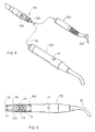
- Figure 4 shows an external connector element 101, a dental turbine handpiece 102 for dental cleaning and a dental handpiece 103 for the polymerization of photosetting resins or compounds according to a second embodiment of the invention.
- the turbine 102 has a hollow cylindrical body that ends in a pin element 104 that is set in rotation by means of a hydraulic or pneumatic system.
- the pin element 104 also has an air and water passage through which air and/or water is sprayed toward the patient's teeth.
- the turbines 102 also have a light source, normally a lamp, which conveys the light toward the work surface through an optical fibre.
- the connector 101 must therefore have a hydraulic and penumatic supply for the turbine 102 and an electrical supply for the light source of the turbine 102.
- the connector 101 can be of various types and models. There are essentially two categories available on the market: fast connectors and locking nut connectors.
- Figure 4 shows a fast connector 101 that has a hollow central tang 105 in which the water passage, the air passage and a possible air return passage are provided.
- Two electrical contacts 106 (only one visible in Figure 4), disposed diametrically opposite each other, are provided on the outer circumference of the connector 101. Said electrical contacts carry the electrical supply for the lamp of the turbine 102. For this purpose the supply voltage is very low. In fact a voltage of about 2.75V is sufficient to light the lamp of the turbine 102.
- the handpiece 103 for the polymerization of photosetting compounds is substantially similar to the handpiece 3 of the first embodiment.
- the handpiece 103 also has as its light source a plurality of LEDS 30 integrated in a printed circuit board 31.
- the handpiece 103 has a connector element 110 shaped so as to be able to be applied to the connector 101 of the turbine 102.
- the outer connector 110 has two electrical contacts 111 and 112 destined to go into contact with the respective contacts 106 provided on the connector 101.
- the connector 110 has a housing 109 able to accommodate the tang 105 of the connector 101.
- the housing 109 is a disabled water and air circuit, since there is no need for water and air under pressure in the handpiece 103.
- the electrical contacts 111 and 112 are connected to the respective electrical wires 113 which carry the electrical supply to an electronic supply circuit 150.
- the electronic supply circuit 150 has a voltage booster or step-up transformer 115.
- the voltage carried by the electrical wires 113 and 114 is the voltage taken from the external connector 101.
- the voltage at the input to the step-up transformer 115 is about 2.75 V which is too low for polarization of the LEDs 30. Consequently the step-up transformer 115 raises the voltage so as to have an adequate bias voltage for the LEDs 30 at its output.
- the step-up transformer 115 can be, for example, a PWM (Pulse Width Modulation) generator which is able to increase the voltage.
- a timer 40 is provided downstream of the step-up transformer 115 which, as in the first embodiment, is connected to a switch, in turn connected to a pushbutton 41 that can be pressed by the operator for turning on or turning off of the LEDs 30.
- the voltage and current from the step-up transformer 115 are sent through a voltage and current stabiliser 24, substantially similar to that used in the first embodiment, so that at the output from the voltage and current stabilizer 24 there is a constant voltage and a direct current for bias of the LEDs 30.
Abstract
Description
- The present invention relates to a dental handpiece for the polymerization of photosetting compounds or resins compatible with the power supply of other handpieces.
- The invention refers in particular to an instrument employed by dental surgeons for the polymerization of photosetting compounds or resins utilised especially in dental prostheses.
- Photosetting resins are applied in a semifluid state to patients' dental prostheses and are then hardened by a polymerization process. Such a polymerization process involves heating the resins for a certain length of time, using a light source that emits blue light, i.e. having an emission spectrum with a wavelength centered around 470 nm.
- Handpieces according to the prior art currently use halogen lamps as their light source. The light coming from the halogen lamps is filtered by dichroic filters, so that a blue light having a light spectrum with a wavelength between 430 and 510 nm is obtained. The light emerging from the dichroic filters is transported, through optic fibres, to the outlet of the dental handpiece, enabling the dentist to direct it onto the resin to be polymerized, applied to the patient's dental prosthesis.
- The known dental handpieces using halogen lamps as polymerizing lamps have various drawbacks.
- In order to achieve polymerization of the resin, the light emerging from the dental handpiece must have a power of approximately 500 mW. Since halogen lamps have a very low power efficiency (efficiency value η = 0.5 -1%), this results in a high energy dissipation by the polymizering lamps, which reaches values between 50 and 100 W.
- For this reason, handpieces for the polymerization of photosetting compounds must have a special power supply, able to supply the polymerizing lamps with a power that ranges from 50 to 100 W. Consequently, the seats in which the patients sit, normally known as dental chair units, provide a connector element connected to the power supply and specifically designed for the polymerizing handpiece.
- Furthermore , with the output power that can be obtained from halogen lamps, rather long resin polymerization times are required; this can be very tiresome both for the patient undergoing the procedure and for the dental surgeon who has to perform it.
- In an attempt to reduce resin polymerization times, handpieces with different light sources have been put on the market. Handpieces are per se known that use as their light source gas-discharge lamps (plasma torches) that emit high-power white light, which is filtered in order to obtain a light beam with an emission spectrum centred on blue. Also known are dental handpieces using laser as their light source, which directly transmit a light beam with an emission spectrum centred on blue.
- With this type of dental handpiece it is possible to obtain a light beam with a power output approximately ten times greater compared to that obtained with halogen lamps, therefore shorter polymerization times are achieved. However, such dental handpieces, apart from being very expensive, have the problem of needing to dissipate a large amount of heat and inevitably they must provide a heat dissipation or cooling system, making them excessively bulky and heavy. Furthermore, such heat dissipation systems often include fans driven by motors which must be powered by the dedicated electrical supply of the polymerizing handpiece.
- Also known, especially at an experimental level, are handpieces for polymerization of photosetting compounds using as their light source LEDs that emit in the blue range.
- All known handpieces using halogen lamps, plasma torches, laser or LEDs as their light source, have an independent electrical supply system, dedicated soleley to the electrical supply of said light sources. This makes the dental handpiece bulky and lacking in versatility because of the purpose-built circuitry provided for such light sources and also the need to provide the dental chair unit with special connectors for the power supply of such handpieces.
- US 5 634 711 discloses a dental handpiece for polymerisation of photosetting compounds or resin using as its polymerising light source a LED matrix. The dental handpiece comprises a power line feed carrying an electrical supply and an electronic circuit connected to the power supply to supply LED matrix.
- US 4 725 232 discloses a dental apparatus comprising a plurality of utility units selectively connectable to a common energy supply unit.
- The object of the invention is to eliminate said drawbacks, providing a dental handpiece for polymerization of photosetting compounds or resins that is compatible with the power supply of other handpieces.
- A further object of the present invention is to provide a handpiece of reduced dimensions and bulk that is versatile, economical and easy to produce.
- These objects are reached, in accordance with the invention, with the characteristics listed in the appended
independent claims 1 and 6. - Preferred embodiments of the invention are apparent from the dependent claims.
- The handpiece according to the invention comprises a connector element shaped so as to be able to connect to external electrical connectors utilised for other types of handpieces, such as for example the handpiece or ultrasound scaler for removal of plaque and caries, or the dental turbine for cleaning and washing dental prostheses.
- This is made possible thanks to the fact that in the handpiece according to the invention LEDs that emit in the blue range are used as the light source. In fact LEDs require a decidedly lower power supply than halogen lamps, plasma torches or laser. This has made it possible to take the electrical supply for bias of the LEDs directly from the electrical supply circuit provided in the external connector of other types of handpieces.
- In the case of connection of the handpiece for polymerization according to the invention to the connector of an ultrasound scaler, the electrical energy for bias of the LEDs is taken from the electrical circuit provided in the connector of the scaler and destined to supply the ultrasound transducer of the scaler.
- For this purpose, in the handpiece according to the invention, an equivalent resonator circuit is provided that must tune the resonance frequency of the supply circuit provided in the external connector of the scaler. Downstream of the equivalent resonance circuit and upstream of the LED assembly of the polymerizing handpiece, a voltage and current stabilizer or regulator is provided in order to generate a constant voltage and direct current signal for correct bias of the LEDs.
- Dental turbines include a light source to illuminate the work surface. For the electrical supply to this light source of the dental turbine, the external connectors of dental turbines carry an electrical supply signal taken from an electrical supply source. In the case of connection of the handpiece according to the invention to an external connector for dental turbines, the supply of the LEDs for polymerization is taken from the electrical supply carried by the external connector of the turbine.
- In this case the voltage supplied by the external connector is too low to be able to supply the LEDs, therefore an electronic voltage booster or step-up transformer circuit capable of providing an adequate voltage to bias the LEDs is provided inside the handpiece according to the invention. Downstream of the step-up transformer circuit a voltage and current stabilizing circuit is provided to maintain a constant voltage and direct current during power supply of the LEDs.
- The advantages of the handpiece for the polymerization of photosetting compounds according to the invention appear evident. Since it can adapt to the connectors used for the power supply of handpieces of other types, it allows the connectors and circuitry specifically dedicated to its supply to be eliminated from the dental chair unit, with considerable economic advantages as regards size and complexity.
- Further characteristics of the invention will be made clearer by the detailed description that follows, referring to purely exemplary and therefore non-limiting embodiments thereof, illustrated in the appended drawings, in which:
- Figure 1 is a perspective view of a first embodiment of the invention illustrating the handpiece for the polymerization of thermosetting compounds according to the invention in a configuration compatible with an ultrasound scaler;
- Figure 2 is an axial sectional view of the handpiece for polymerization of photosetting compounds of Figure 1;
- Figure 3 is an electrical block diagram illustrating the electronic circuit for supply of the handpiece of Figure 2;
- Figure 4 is a perspective view of a second embodiment of the invention, illustrating the handpiece for polymerization of photosetting compounds according to the invention in a configuration compatible with a dental turbine;
- Figure 5 is an axial sectional view of the handpiece for polymerization of photosetting compounds of Figure 4;
- Figure 6 is an electrical block diagram, illustrating the electronic circuit for the supply of the handpiece of Figure 5.
-
- Figure 1 shows an
external connector element 1, a handpiece orultrasound scaler 2 for removal of tartar and scale and adental handpiece 3 for polymerization of photosetting compounds or resins, according to a first embodiment of the invention. - The
scaler 2, per se known, comprises a hollow cylindrical body inside which is positioned a piezoceramic resonator, which acts as a sound wave concentrator to set in vibration a hook-shaped workpiece suitable for removal of plaque and scale from the patient's teeth. - In order to act as a vibrator, the piezoceramic resonator of the
scaler 2 must be supplied with an alternating sinusoidal voltage of about 160-200 Volt r.m.s. at an oscillation frequency ranging from 26 KHz to 30 KHz. This supply signal is provided by theconnector 1, per se known. - The
external connector 1, specially designed for thescaler 2, is provided with twoholes 5 and 6 for electrical coupling and a hole 7 for hydraulic coupling. Theholes 5 and 6 are connected to respective electrical supply wires upstream of which an electrical transformer (not shown) is provided. Said transformer, generally provided on a dental chair unit, serves to transform the mains voltage (220 Volt alternating current) into a sinusoidal voltage of 160-200 Volt r.m.s. at a frequency of 26-30 KHz, which is suitable for operating the piezoceramic resonator of thescaler 2. The hole 7, on the other hand, is connected to a hydraulic system to send jets of water under pressure which are conveyed through thescaler 2 to exit from the tip of theworkpiece 4. The electrical supply wires and the hydraulic supply tube are enclosed in asheath 8 and directed toward the electrical supply source and the hydraulic supply source provided in the dental chair unit or in the electrical and hydraulic network. - The
scaler 4, in order to be able to couple to theconnector element 1, must have a complementary connecting element 9 that provides two electrical contacts that engage inside theholes 5 and 6 and a hydraulic coupling element that engages in the hole 7. - The
dental handpiece 3 for the polymerization of photosetting compounds or resins usesLEDs 30 as the light source. In the present embodiments of the invention a group ofsemiconductor LEDs 30 integrated on a printedcircuit board 31 is shown (Fig 2), although other types of LED commonly available on the market can be employed. - Consequently the
handpiece 3 for the polymerization of photosetting compounds according to the invention, in order to be able to connect to theconnector 1 of thescaler 2, has aconnector element 10 substantially similar to the connector element 9 of thescaler 2. - As shown in Figure 2, the
connector element 10 provides twoelectrical contacts holes 5 and 6 of the electrical circuit of theconnector 1 and acoupling element 130 that engages in the hole 7 of the hydraulic circuit of theconnnector 1. Thecoupling element 130 serves simply to plug the hole 7, because in the polymerizinghandpiece 3 there is no need to have jets of water at high pressure. - The
electrical contacts electrical wires electronic circuit 50 that serves to supply theLEDs 30. Theelectronic circuit 50 has aresonant circuit 15. Theresonant circuit 15 can be any type of resonant circuit able to tune the frequency of 26-30 KHz of the electrical supply signal coming from theexternal connector element 1. - In Figure 3, by way of example, the
resonance circuit 15 is made up of a parallel resonator comprising acapacitance 16 in parallel to aresistance 17 in series with acapacitance 18. - Downstream of the resonating circuit 15 a
transformer 19 is provided to transform the output voltage from the resonatingcircuit 15 into a voltage suitable for bias of theLEDs 30. Thevoltage transformer 19 can be made in various ways. Figure 3 shows a primary winding 20 mutually coupled with a secondary winding 21. - Downstream of the transformer 19 a
rectifier 22 can be provided to rectify the wave shape of the electrical supply signal. Downstream of the rectifier 22 afilter 23 can also be provided to filter possible disturbances of the electrical supply signal. - The supply signal from the
filter 23 is sent to a voltage andcurrent stabilizer 24 able to generate as its output a constant voltage signal and a direct current signal for bias of theLEDs 30. - Depending on the type of LEDs used, they may require different bias currents and voltages. By way of example, in the present
embodiment semiconducter LEDs 30, preferably gallium arsenide, are used, integrated in a printedcircuit board 31 disposed inside the body of thehandpiece 3. TheLEDs 30 are coupled to an optical fibre orlight guide 32 to convey the light to the head of the handpiece, so as to be able to direct it toward the point of work. - Each
gallium arsenide LED 30 requires a bias voltage of about 3.3 V and a bias current of about 20 mA direct or greater currents for pulse supply. In the present embodiment, Figure 3 shows a matrix of twelveLEDs 30 made by means of three parallel arrays, each array comprising four LEDs in series. In this case the voltage from the voltage andcurrent stabilizer 24 will be greater than or equal to 13.2 V, in order to have a voltage drop of 3.3V on eachLED 30. - Clearly other configurations of the
LEDs 30 are possible. TheLEDs 30 can be connected in series or in parallel depending on the voltage and current from the voltage andcurrent stabilizer 24. - Upstream and downstream of the voltage stabilizer 24 a
switch 45 is provided, shown downstream in Figure 3. When theswitch 45 is turned on or off the supply to theLEDs 30 is enabled or disabled. Theswitch 45 is controlled by apushbutton 41 protruding outward from the body of thehandpiece 3, so that it can be pushed by an operator. Theswitch 45 can be connected to a timer orsystem clock 40. - In this manner when the operator presses the
button 41, theswitch 45 enables the supply of theLEDs 30 that begin to emit blue light. At the same time thesystem clock 40 begins to count for a fixed period of time, necessary for polymerisation of photosetting compounds (for example, 20 seconds). After this period of time the power supply of theLEDs 30 is turned off and therefore LEDs turn off. Pressing thebutton 41 during the operating cycle causes the turning off of the LEDs and resets thesystem clock 40 for the next cycle. - In Figs. 4-6 a second embodiment of the invention is shown in which similar or corresponding elements are denoted by the same reference numerals used in the first embodiment.
- Figure 4 shows an
external connector element 101, adental turbine handpiece 102 for dental cleaning and adental handpiece 103 for the polymerization of photosetting resins or compounds according to a second embodiment of the invention. - The
turbine 102 has a hollow cylindrical body that ends in apin element 104 that is set in rotation by means of a hydraulic or pneumatic system. Thepin element 104 also has an air and water passage through which air and/or water is sprayed toward the patient's teeth. Theturbines 102 also have a light source, normally a lamp, which conveys the light toward the work surface through an optical fibre. - The
connector 101 must therefore have a hydraulic and penumatic supply for theturbine 102 and an electrical supply for the light source of theturbine 102. Theconnector 101 can be of various types and models. There are essentially two categories available on the market: fast connectors and locking nut connectors. - Figure 4 shows a
fast connector 101 that has a hollowcentral tang 105 in which the water passage, the air passage and a possible air return passage are provided. - Two electrical contacts 106 (only one visible in Figure 4), disposed diametrically opposite each other, are provided on the outer circumference of the
connector 101. Said electrical contacts carry the electrical supply for the lamp of theturbine 102. For this purpose the supply voltage is very low. In fact a voltage of about 2.75V is sufficient to light the lamp of theturbine 102. - The
handpiece 103 for the polymerization of photosetting compounds is substantially similar to thehandpiece 3 of the first embodiment. Thehandpiece 103 also has as its light source a plurality ofLEDS 30 integrated in a printedcircuit board 31. - The
handpiece 103 has aconnector element 110 shaped so as to be able to be applied to theconnector 101 of theturbine 102. As shown in Figure 5, theouter connector 110 has twoelectrical contacts respective contacts 106 provided on theconnector 101. Theconnector 110 has ahousing 109 able to accommodate thetang 105 of theconnector 101. Thehousing 109 is a disabled water and air circuit, since there is no need for water and air under pressure in thehandpiece 103. - The
electrical contacts electrical wires 113 which carry the electrical supply to anelectronic supply circuit 150. Theelectronic supply circuit 150 has a voltage booster or step-uptransformer 115. The voltage carried by theelectrical wires external connector 101. Thus the voltage at the input to the step-uptransformer 115 is about 2.75 V which is too low for polarization of theLEDs 30. Consequently the step-uptransformer 115 raises the voltage so as to have an adequate bias voltage for theLEDs 30 at its output. The step-uptransformer 115 can be, for example, a PWM (Pulse Width Modulation) generator which is able to increase the voltage. - Downstream of the step-up transformer 115 a
timer 40 is provided which, as in the first embodiment, is connected to a switch, in turn connected to apushbutton 41 that can be pressed by the operator for turning on or turning off of theLEDs 30. - The voltage and current from the step-up
transformer 115 are sent through a voltage andcurrent stabiliser 24, substantially similar to that used in the first embodiment, so that at the output from the voltage andcurrent stabilizer 24 there is a constant voltage and a direct current for bias of theLEDs 30. - Various modifications and changes within the reach of a person skilled in the art can be made to the present embodiments without thereby departing from the scope of the invention expressed in the appended claims.
Claims (10)
- A dental handpiece (3) for the polymerization of photosetting compounds or resins using as its polymerizing light source at least one LED (30), comprising:wherein said connector element (10) of the handpiece for polymerization of photosetting compounds can be adapted to the external connector (1) of a handpiece or ultrasound scaler (2), in order to be able to take the electrical power, destined for the resonator of the scaler (2), and convey it, through the electronic circuit (50), toward the LED light source (30), anda connector element (10) that can be adapted to external connectors (1) of other types of handpieces carrying an electrical supply in order to be able to take said electrical supply, andan electronic circuit (50) connected to said connector element (10) to process the electrical supply signal in order to be able to supply said LED light source (30),
wherein said electronic supply circuit (50) provides a resonance circuit (15) able to tune the supply frequency coming from said external connector (1), said frequency being able to set in vibration the resonator provided in the scaler (2). - A dental handpiece (3) according to claim 1, characterized in that said resonance circuit (15) is a parallel resonator that provides a capacitance (16) in parallel to a resistance (17) in series with a capacitance (18).
- A dental handpiece (3) according to claim 1 or 2, characterized in that downstream of the resonance circuit (15) a voltage transformer (15) is provided to generate an adequate bias voltage for said LEDs (30).
- A dental handpiece (3) according to any one of preceding claims, characterized in that said electronic supply circuit (50) provides a rectifier (22) to rectify the electrical supply signal for bias of the LEDs (30).
- A dental handpiece (3) according to any one of preceding claims, characterized in that said electronic supply circuit (50) provides a filter (23) to filter the disturbances of the electrical supply system.
- A dental handpiece (103) for the polymerization of photosetting compounds or resins using as its polymerizing light source at least one LED (30), comprising:wherein said connector element (110) of the handpiece for polymerization of photosetting compounds can be adapted to the external connector (101) of a dental turbine (102), in order to be able to take the electrical power destined to the light source of the dental turbine (102), and convey it, through the electronic circuit (150) towards the LED light source (30) ofthe handpiece (103), anda connector element (110) that can be adapted to external connectors (101) of other types of handpieces carrying an electrical supply in order to be able to take said electrical supply, andan electronic circuit (150) connected to said connector element (110) to process the electrical supply signal in order to be able to supply said LED light source (30),
wherein said electronic supply circuit (150) provides a step-up transformer (115) to generate an adequate bias voltage for the LEDs (30). - A dental handpiece (103) according to claim 6, characterized in that said step-up transformer (115) is a PWM (Pulse Width Modulation) booster, able to increase the output voltage and current to have an adequate bias voltage and current for the LEDs (30).
- A dental handpiece (3; 103) according to any one of the preceding claims, characterized in that in said supply circuit (50; 150) of said handpiece, upstream of the LEDs (30), a voltage and current stabilizer (24) is provided such as to supply said LEDs (30) with a constant voltage signal and a direct current signal, for bias thereof.
- A dental handpiece (3; 103) according to any one of the preceding claims, characterized in that in the supply circuit (50; 150) of said handpiece a switch (45) is provided, controlled by a pushbutton that can be pressed by the operator to enable turning on and turning off of said LEDs (30).
- A dental handpiece (3; 103) according to claim 9, characterized in that said switch (45) is connected to a timer (40) that closes the switch (45) for a suitable period of time for polymerisation of the photosetting compounds so as to be able to direct the light emitted by the LEDs (30) onto the photosetting compounds for this period of time.
Priority Applications (7)
| Application Number | Priority Date | Filing Date | Title |
|---|---|---|---|
| DK99830740T DK1103232T3 (en) | 1999-11-29 | 1999-11-29 | Dental handpiece for polymerizing photo-curing compounds or resins compatible with the energy supply of other handpieces |
| AT99830740T ATE275885T1 (en) | 1999-11-29 | 1999-11-29 | DENTAL PHOTOPOLYMERIZATION HANDPIECE COMPATIBLE WITH THE POWER SUPPLY DEVICE OF OTHER HANDPIECES |
| PT99830740T PT1103232E (en) | 1999-11-29 | 1999-11-29 | MAO DENTARY POTENTIAL FOR PHOTOPOLYMERIZATION COMPATIBLE WITH THE SOURCE OF FOOD OF OTHER MAO POCKETS |
| DE69920236T DE69920236T2 (en) | 1999-11-29 | 1999-11-29 | Dental handpiece for photopolymerization compatible with the power supply device of other handpieces |
| ES99830740T ES2229663T3 (en) | 1999-11-29 | 1999-11-29 | DENTAL ACCESSORY FOR PHOTOPOLIMERIZATION COMPATIBLE WITH THE POWER SUPPLY OF OTHER ACCESSORIES. |
| EP99830740A EP1103232B1 (en) | 1999-11-29 | 1999-11-29 | A dental handpiece for the photopolymerization compatible with the power supply of other handpieces |
| US10/155,762 US6793490B2 (en) | 1999-11-29 | 2002-05-24 | Dental handpiece for the polymerization of photosetting compounds or resins, compatible with the power supply of other handpieces |
Applications Claiming Priority (2)
| Application Number | Priority Date | Filing Date | Title |
|---|---|---|---|
| EP99830740A EP1103232B1 (en) | 1999-11-29 | 1999-11-29 | A dental handpiece for the photopolymerization compatible with the power supply of other handpieces |
| US10/155,762 US6793490B2 (en) | 1999-11-29 | 2002-05-24 | Dental handpiece for the polymerization of photosetting compounds or resins, compatible with the power supply of other handpieces |
Publications (2)
| Publication Number | Publication Date |
|---|---|
| EP1103232A1 EP1103232A1 (en) | 2001-05-30 |
| EP1103232B1 true EP1103232B1 (en) | 2004-09-15 |
Family
ID=32044377
Family Applications (1)
| Application Number | Title | Priority Date | Filing Date |
|---|---|---|---|
| EP99830740A Expired - Lifetime EP1103232B1 (en) | 1999-11-29 | 1999-11-29 | A dental handpiece for the photopolymerization compatible with the power supply of other handpieces |
Country Status (7)
| Country | Link |
|---|---|
| US (1) | US6793490B2 (en) |
| EP (1) | EP1103232B1 (en) |
| AT (1) | ATE275885T1 (en) |
| DE (1) | DE69920236T2 (en) |
| DK (1) | DK1103232T3 (en) |
| ES (1) | ES2229663T3 (en) |
| PT (1) | PT1103232E (en) |
Cited By (4)
| Publication number | Priority date | Publication date | Assignee | Title |
|---|---|---|---|---|
| US7989839B2 (en) | 2002-08-23 | 2011-08-02 | Koninklijke Philips Electronics, N.V. | Method and apparatus for using light emitting diodes |
| US8096691B2 (en) | 1997-09-25 | 2012-01-17 | Koninklijke Philips Electronics N V | Optical irradiation device |
| US9066777B2 (en) | 2009-04-02 | 2015-06-30 | Kerr Corporation | Curing light device |
| US9726435B2 (en) | 2002-07-25 | 2017-08-08 | Jonathan S. Dahm | Method and apparatus for using light emitting diodes for curing |
Families Citing this family (39)
| Publication number | Priority date | Publication date | Assignee | Title |
|---|---|---|---|---|
| US6200134B1 (en) | 1998-01-20 | 2001-03-13 | Kerr Corporation | Apparatus and method for curing materials with radiation |
| ES2229663T3 (en) * | 1999-11-29 | 2005-04-16 | Mectron S.R.L. | DENTAL ACCESSORY FOR PHOTOPOLIMERIZATION COMPATIBLE WITH THE POWER SUPPLY OF OTHER ACCESSORIES. |
| EP1441659A1 (en) * | 2001-10-17 | 2004-08-04 | Dentsply International, Inc. | Unitized modular ultrasonic handpiece cable connector |
| US7182597B2 (en) | 2002-08-08 | 2007-02-27 | Kerr Corporation | Curing light instrument |
| FR2847455A1 (en) * | 2002-11-27 | 2004-05-28 | Francois Duret | Light-emitting diode device for photo polymerizing resins comprises a light-transmitting front part reversibly connected to an electricity-supplying back part |
| US6994546B2 (en) * | 2002-12-18 | 2006-02-07 | Ultradent Products, Inc. | Light curing device with detachable power supply |
| ITBO20030021A1 (en) * | 2003-01-17 | 2004-07-18 | Cefla Soc Coop A R L Ora Cefla Societa Cooperat | POLYMERIZING LAMP FOR THE POLYMERIZATION OF COMPOUNDS |
| AT411867B (en) * | 2003-02-20 | 2004-07-26 | W & H Dentalwerk Buermoos Gmbh | Adapter for medical instrument e.g. for dental work, provides matching of polarity of contacts within hand-piece |
| US6918762B2 (en) | 2003-03-21 | 2005-07-19 | Kerr Corporation | Light-generating instrument |
| US20050053895A1 (en) * | 2003-09-09 | 2005-03-10 | The Procter & Gamble Company Attention: Chief Patent Counsel | Illuminated electric toothbrushes emitting high luminous intensity toothbrush |
| US20060018123A1 (en) * | 2004-07-02 | 2006-01-26 | Rose Eric P | Curing light having a reflector |
| AU2005270047B2 (en) * | 2004-07-02 | 2011-06-02 | Discus Dental, Llc. | Dental light device having an improved heat sink |
| AU2005270014A1 (en) * | 2004-07-02 | 2006-02-09 | Discus Dental, Llc. | Curing light having a reflector |
| US20060142744A1 (en) * | 2004-07-27 | 2006-06-29 | Dmitri Boutoussov | Identification connector for a medical laser handpiece |
| ITBO20050096A1 (en) | 2005-02-24 | 2006-08-25 | Italia Medica S R L | HANDPIECE FOR ULTRASOUND ELECTROMEDICAL EQUIPMENT |
| US20060252005A1 (en) * | 2005-05-06 | 2006-11-09 | Feinbloom Richard E | Apparatus for providing radiation at multiple wavelengths and method of operating same |
| US8113830B2 (en) | 2005-05-27 | 2012-02-14 | Kerr Corporation | Curing light instrument |
| EP1759653A1 (en) * | 2005-09-06 | 2007-03-07 | W & H Dentalwerk Bürmoos GmbH | Adaptor for a medical handpiece, medical handpiece and medical power unit |
| US20070212385A1 (en) * | 2006-03-13 | 2007-09-13 | David Nathaniel E | Fluidic Tissue Augmentation Compositions and Methods |
| DE102006027624A1 (en) * | 2006-06-13 | 2007-12-20 | Elexxion Gmbh | Handpiece for in particular medical laser applications |
| US20080101073A1 (en) * | 2006-11-01 | 2008-05-01 | Discus Dental, Llc | Dental Light Devices Having an Improved Heat Sink |
| US20080241785A1 (en) * | 2007-03-30 | 2008-10-02 | Cms Dental Aps | Handset and optical tip for photosynthesis |
| US20100330523A1 (en) * | 2007-03-30 | 2010-12-30 | Cms Dental Aps | Optical tip for photosynthesis |
| US20090081605A1 (en) * | 2007-09-25 | 2009-03-26 | Ondine International, Ltd. | Photodynamic therapy device adapted for use with scaler |
| US20090208894A1 (en) * | 2008-02-18 | 2009-08-20 | Discus Dental, Llc | Curing Light |
| US8197501B2 (en) * | 2008-03-20 | 2012-06-12 | Medtronic Xomed, Inc. | Control for a powered surgical instrument |
| GB2459438B (en) * | 2008-04-10 | 2010-10-06 | Kythera Biopharmaceuticals Inc | Systems and methods for transdermal photo-polymerization |
| US20100006109A1 (en) * | 2008-07-10 | 2010-01-14 | Mcginnis William J | Ventilating mouthguard device, kit and method of using same |
| US9072572B2 (en) | 2009-04-02 | 2015-07-07 | Kerr Corporation | Dental light device |
| ATE533427T1 (en) * | 2009-12-10 | 2011-12-15 | W & H Dentalwerk Buermoos Gmbh | MEDICAL, IN PARTICULAR DENTAL, TREATMENT DEVICE FOR DELIVERING A MEDIUM |
| WO2011123738A1 (en) * | 2010-04-01 | 2011-10-06 | Ultradent Products, Inc. | Dental curing light having long pulse mode for more extensive curing |
| EP2386263B1 (en) * | 2010-05-11 | 2014-02-26 | Bien-Air Holding SA | Lighting module with light-emitting diodes for a surgical or dental handpiece |
| DK177210B1 (en) | 2011-02-24 | 2012-07-02 | Cms Dental Aps | A dental instrument |
| DE102011077607A1 (en) * | 2011-06-16 | 2012-12-20 | Ferton Holding S.A. | Handpiece for e.g. ultrasonic scaler system for removing tartar from teeth of patient, has supply unit supplying electrical power to LEDs, where electrical power is branched off from electrical power supplied to electromechanical vibrator |
| KR20170058977A (en) | 2014-09-17 | 2017-05-29 | 개리슨 덴탈 솔루션즈, 엘엘씨 | Dental curing light |
| US9456948B1 (en) * | 2015-03-06 | 2016-10-04 | Sargon Lazarof | Dental chair |
| CN104905885B (en) * | 2015-06-15 | 2017-01-25 | 杭州四方医疗器械有限公司 | LED circuit board for handle of dental descaler |
| USD810293S1 (en) | 2017-01-20 | 2018-02-13 | Garrison Dental Solutions, Llc | Dental instrument |
| US10368969B2 (en) | 2017-04-21 | 2019-08-06 | Xlr8 Holdings, Llc | Hand-held device utilizing an activation mechanism which spans the circumference of said device |
Family Cites Families (9)
| Publication number | Priority date | Publication date | Assignee | Title |
|---|---|---|---|---|
| DE2549177C3 (en) * | 1975-11-03 | 1985-10-03 | Siemens AG, 1000 Berlin und 8000 München | Coupling device for dental handpieces |
| DE3243294A1 (en) * | 1982-11-23 | 1984-05-24 | Siemens AG, 1000 Berlin und 8000 München | CONTROL DEVICE FOR INSTRUMENTS HOLDED IN A DENTAL DEVICE |
| JPS6190650A (en) * | 1984-10-12 | 1986-05-08 | 株式会社 吉田製作所 | Dental treating apparatus |
| US5420768A (en) * | 1993-09-13 | 1995-05-30 | Kennedy; John | Portable led photocuring device |
| IT1296089B1 (en) * | 1997-11-10 | 1999-06-09 | Mectron Di Bianchetti Fernando | DENTAL HANDPIECE WITH LIGHT SOURCE FOR DIAGNOSTIC PURPOSE |
| US6331111B1 (en) * | 1999-09-24 | 2001-12-18 | Cao Group, Inc. | Curing light system useful for curing light activated composite materials |
| EP1090607A1 (en) * | 1999-10-08 | 2001-04-11 | Mectron S.R.L. | A dental handpiece for the polymerization of photosetting compounds or resins |
| EP1090608A1 (en) * | 1999-10-08 | 2001-04-11 | Mectron S.R.L. | A dental handpiece for the polymerization of photosetting compounds or resins |
| ES2229663T3 (en) * | 1999-11-29 | 2005-04-16 | Mectron S.R.L. | DENTAL ACCESSORY FOR PHOTOPOLIMERIZATION COMPATIBLE WITH THE POWER SUPPLY OF OTHER ACCESSORIES. |
-
1999
- 1999-11-29 ES ES99830740T patent/ES2229663T3/en not_active Expired - Lifetime
- 1999-11-29 DK DK99830740T patent/DK1103232T3/en active
- 1999-11-29 DE DE69920236T patent/DE69920236T2/en not_active Expired - Lifetime
- 1999-11-29 AT AT99830740T patent/ATE275885T1/en active
- 1999-11-29 PT PT99830740T patent/PT1103232E/en unknown
- 1999-11-29 EP EP99830740A patent/EP1103232B1/en not_active Expired - Lifetime
-
2002
- 2002-05-24 US US10/155,762 patent/US6793490B2/en not_active Expired - Fee Related
Cited By (4)
| Publication number | Priority date | Publication date | Assignee | Title |
|---|---|---|---|---|
| US8096691B2 (en) | 1997-09-25 | 2012-01-17 | Koninklijke Philips Electronics N V | Optical irradiation device |
| US9726435B2 (en) | 2002-07-25 | 2017-08-08 | Jonathan S. Dahm | Method and apparatus for using light emitting diodes for curing |
| US7989839B2 (en) | 2002-08-23 | 2011-08-02 | Koninklijke Philips Electronics, N.V. | Method and apparatus for using light emitting diodes |
| US9066777B2 (en) | 2009-04-02 | 2015-06-30 | Kerr Corporation | Curing light device |
Also Published As
| Publication number | Publication date |
|---|---|
| US6793490B2 (en) | 2004-09-21 |
| PT1103232E (en) | 2005-01-31 |
| US20030219694A1 (en) | 2003-11-27 |
| DE69920236D1 (en) | 2004-10-21 |
| ES2229663T3 (en) | 2005-04-16 |
| DK1103232T3 (en) | 2005-01-10 |
| EP1103232A1 (en) | 2001-05-30 |
| ATE275885T1 (en) | 2004-10-15 |
| DE69920236T2 (en) | 2005-09-29 |
Similar Documents
| Publication | Publication Date | Title |
|---|---|---|
| EP1103232B1 (en) | A dental handpiece for the photopolymerization compatible with the power supply of other handpieces | |
| US6325791B1 (en) | Method of using a cordless medical laser to cure composites | |
| US6440122B1 (en) | Method of using a cordless pumped μ-chip medical laser to cure composites | |
| EP0914808B1 (en) | Dental hand instrument with incorporated light source | |
| US7104794B2 (en) | Ultrasonic dental tool having a light source | |
| EP0914809B1 (en) | Dental hand instrument with incorporated light source for diagnostic purposes | |
| US6746473B2 (en) | Therapeutic laser device | |
| EP1314402B1 (en) | Optical system for a dental Handpiece for polymerization of photosetting compounds or resins | |
| KR101448860B1 (en) | Portable treatment apparatus of uv and laser complex type | |
| EP1090607A1 (en) | A dental handpiece for the polymerization of photosetting compounds or resins | |
| US8439927B2 (en) | Method of using a multi-probe laser device | |
| WO1995007731A1 (en) | A portable light emitting apparatus with a semiconductor emitter array | |
| AU2002320106A1 (en) | Improved hand-held laser device for skin treatment | |
| EP1090608A1 (en) | A dental handpiece for the polymerization of photosetting compounds or resins | |
| US5683246A (en) | Illumination apparatus for dental handpiece | |
| JPS6141578B2 (en) | ||
| US20220273399A1 (en) | Systems combining therapeutic lasers and curing lights | |
| US20130221863A1 (en) | Generator suitable for powering a dental curing light | |
| ITMI982511A1 (en) | DENTAL HANDPIECES FOR THE POLYMERIZATION OF PHOTO-HARDENING ORESINE COMPOUNDS | |
| WO2007045249A1 (en) | A dental handpiece | |
| JPH0580219B2 (en) | ||
| JPH0576306B2 (en) | ||
| PL149747B1 (en) | Apparatus for removal of tartar by ultrasound | |
| JPH07275260A (en) | Dental hand piece with built-in lighting system |
Legal Events
| Date | Code | Title | Description |
|---|---|---|---|
| PUAI | Public reference made under article 153(3) epc to a published international application that has entered the european phase |
Free format text: ORIGINAL CODE: 0009012 |
|
| AK | Designated contracting states |
Kind code of ref document: A1 Designated state(s): AT BE CH CY DE DK ES FI FR GB GR IE IT LI LU MC NL PT SE |
|
| AX | Request for extension of the european patent |
Free format text: AL;LT;LV;MK;RO;SI |
|
| 17P | Request for examination filed |
Effective date: 20011009 |
|
| AKX | Designation fees paid |
Free format text: AT BE CH CY DE DK ES FI FR GB GR IE IT LI LU MC NL PT SE |
|
| 17Q | First examination report despatched |
Effective date: 20031125 |
|
| GRAP | Despatch of communication of intention to grant a patent |
Free format text: ORIGINAL CODE: EPIDOSNIGR1 |
|
| GRAS | Grant fee paid |
Free format text: ORIGINAL CODE: EPIDOSNIGR3 |
|
| GRAA | (expected) grant |
Free format text: ORIGINAL CODE: 0009210 |
|
| AK | Designated contracting states |
Kind code of ref document: B1 Designated state(s): AT BE CH CY DE DK ES FI FR GB GR IE IT LI LU MC NL PT SE |
|
| PG25 | Lapsed in a contracting state [announced via postgrant information from national office to epo] |
Ref country code: CY Free format text: LAPSE BECAUSE OF FAILURE TO SUBMIT A TRANSLATION OF THE DESCRIPTION OR TO PAY THE FEE WITHIN THE PRESCRIBED TIME-LIMIT Effective date: 20040915 |
|
| REG | Reference to a national code |
Ref country code: GB Ref legal event code: FG4D Ref country code: CH Ref legal event code: EP |
|
| REG | Reference to a national code |
Ref country code: IE Ref legal event code: FG4D |
|
| REF | Corresponds to: |
Ref document number: 69920236 Country of ref document: DE Date of ref document: 20041021 Kind code of ref document: P |
|
| REG | Reference to a national code |
Ref country code: SE Ref legal event code: TRGR |
|
| REG | Reference to a national code |
Ref country code: CH Ref legal event code: NV Representative=s name: A. BRAUN, BRAUN, HERITIER, ESCHMANN AG PATENTANWAE |
|
| REG | Reference to a national code |
Ref country code: GR Ref legal event code: EP Ref document number: 20040404353 Country of ref document: GR |
|
| REG | Reference to a national code |
Ref country code: PT Ref legal event code: SC4A Effective date: 20041207 |
|
| REG | Reference to a national code |
Ref country code: ES Ref legal event code: FG2A Ref document number: 2229663 Country of ref document: ES Kind code of ref document: T3 |
|
| PLAQ | Examination of admissibility of opposition: information related to despatch of communication + time limit deleted |
Free format text: ORIGINAL CODE: EPIDOSDOPE2 |
|
| PLAR | Examination of admissibility of opposition: information related to receipt of reply deleted |
Free format text: ORIGINAL CODE: EPIDOSDOPE4 |
|
| PLBQ | Unpublished change to opponent data |
Free format text: ORIGINAL CODE: EPIDOS OPPO |
|
| PLBI | Opposition filed |
Free format text: ORIGINAL CODE: 0009260 |
|
| PLAX | Notice of opposition and request to file observation + time limit sent |
Free format text: ORIGINAL CODE: EPIDOSNOBS2 |
|
| ET | Fr: translation filed | ||
| 26 | Opposition filed |
Opponent name: W&H DENTALWERK BUERMOOS GMBH Effective date: 20050614 |
|
| NLR1 | Nl: opposition has been filed with the epo |
Opponent name: W&H DENTALWERK BUERMOOS GMBH |
|
| PLAF | Information modified related to communication of a notice of opposition and request to file observations + time limit |
Free format text: ORIGINAL CODE: EPIDOSCOBS2 |
|
| PLBB | Reply of patent proprietor to notice(s) of opposition received |
Free format text: ORIGINAL CODE: EPIDOSNOBS3 |
|
| RAP2 | Party data changed (patent owner data changed or rights of a patent transferred) |
Owner name: MECTRON S.P.A. |
|
| NLT2 | Nl: modifications (of names), taken from the european patent patent bulletin |
Owner name: MECTRON S.P.A. Effective date: 20061206 |
|
| PLBP | Opposition withdrawn |
Free format text: ORIGINAL CODE: 0009264 |
|
| PLBD | Termination of opposition procedure: decision despatched |
Free format text: ORIGINAL CODE: EPIDOSNOPC1 |
|
| PLBM | Termination of opposition procedure: date of legal effect published |
Free format text: ORIGINAL CODE: 0009276 |
|
| STAA | Information on the status of an ep patent application or granted ep patent |
Free format text: STATUS: OPPOSITION PROCEDURE CLOSED |
|
| 27C | Opposition proceedings terminated |
Effective date: 20070721 |
|
| NLR2 | Nl: decision of opposition |
Effective date: 20070721 |
|
| REG | Reference to a national code |
Ref country code: CH Ref legal event code: PFA Owner name: MECTRON S.R.L. Free format text: MECTRON S.R.L.#VIA LORETO 15/A#16042 CARASCO (GENOVA) (IT) -TRANSFER TO- MECTRON S.R.L.#VIA LORETO 15/A#16042 CARASCO (GENOVA) (IT) |
|
| PLAB | Opposition data, opponent's data or that of the opponent's representative modified |
Free format text: ORIGINAL CODE: 0009299OPPO |
|
| PGFP | Annual fee paid to national office [announced via postgrant information from national office to epo] |
Ref country code: MC Payment date: 20081008 Year of fee payment: 10 |
|
| PG25 | Lapsed in a contracting state [announced via postgrant information from national office to epo] |
Ref country code: MC Free format text: LAPSE BECAUSE OF NON-PAYMENT OF DUE FEES Effective date: 20091130 |
|
| PGFP | Annual fee paid to national office [announced via postgrant information from national office to epo] |
Ref country code: NL Payment date: 20101116 Year of fee payment: 12 Ref country code: IE Payment date: 20101115 Year of fee payment: 12 Ref country code: DK Payment date: 20101124 Year of fee payment: 12 Ref country code: AT Payment date: 20101125 Year of fee payment: 12 |
|
| PGFP | Annual fee paid to national office [announced via postgrant information from national office to epo] |
Ref country code: PT Payment date: 20101019 Year of fee payment: 12 Ref country code: LU Payment date: 20101123 Year of fee payment: 12 Ref country code: FI Payment date: 20101129 Year of fee payment: 12 |
|
| PGFP | Annual fee paid to national office [announced via postgrant information from national office to epo] |
Ref country code: BE Payment date: 20101021 Year of fee payment: 12 Ref country code: SE Payment date: 20101125 Year of fee payment: 12 Ref country code: GR Payment date: 20101022 Year of fee payment: 12 Ref country code: IT Payment date: 20101129 Year of fee payment: 12 Ref country code: GB Payment date: 20101026 Year of fee payment: 12 |
|
| PGFP | Annual fee paid to national office [announced via postgrant information from national office to epo] |
Ref country code: ES Payment date: 20110615 Year of fee payment: 12 |
|
| REG | Reference to a national code |
Ref country code: DE Ref legal event code: R119 Ref document number: 69920236 Country of ref document: DE Effective date: 20110531 |
|
| REG | Reference to a national code |
Ref country code: DE Ref legal event code: R073 Ref document number: 69920236 Country of ref document: DE |
|
| REG | Reference to a national code |
Ref country code: DE Ref legal event code: R073 Ref document number: 69920236 Country of ref document: DE |
|
| PG25 | Lapsed in a contracting state [announced via postgrant information from national office to epo] |
Ref country code: DE Free format text: LAPSE BECAUSE OF NON-PAYMENT OF DUE FEES Effective date: 20110531 |
|
| REG | Reference to a national code |
Ref country code: DE Ref legal event code: R074 Ref document number: 69920236 Country of ref document: DE |
|
| PGFP | Annual fee paid to national office [announced via postgrant information from national office to epo] |
Ref country code: CH Payment date: 20111108 Year of fee payment: 13 Ref country code: FR Payment date: 20111213 Year of fee payment: 13 |
|
| REG | Reference to a national code |
Ref country code: DE Ref legal event code: R074 Ref document number: 69920236 Country of ref document: DE Effective date: 20120122 Ref country code: DE Ref legal event code: R074 Ref document number: 69920236 Country of ref document: DE Effective date: 20120119 |
|
| PGRI | Patent reinstated in contracting state [announced from national office to epo] |
Ref country code: DE Effective date: 20120119 |
|
| BERE | Be: lapsed |
Owner name: *MECTRON S.R.L. Effective date: 20111130 |
|
| PGFP | Annual fee paid to national office [announced via postgrant information from national office to epo] |
Ref country code: DE Payment date: 20111130 Year of fee payment: 13 |
|
| REG | Reference to a national code |
Ref country code: PT Ref legal event code: MM4A Free format text: LAPSE DUE TO NON-PAYMENT OF FEES Effective date: 20120529 |
|
| REG | Reference to a national code |
Ref country code: NL Ref legal event code: V1 Effective date: 20120601 |
|
| REG | Reference to a national code |
Ref country code: DK Ref legal event code: EBP |
|
| REG | Reference to a national code |
Ref country code: SE Ref legal event code: EUG |
|
| REG | Reference to a national code |
Ref country code: GR Ref legal event code: ML Ref document number: 20040404353 Country of ref document: GR Effective date: 20120605 |
|
| GBPC | Gb: european patent ceased through non-payment of renewal fee |
Effective date: 20111129 |
|
| PG25 | Lapsed in a contracting state [announced via postgrant information from national office to epo] |
Ref country code: NL Free format text: LAPSE BECAUSE OF NON-PAYMENT OF DUE FEES Effective date: 20120601 |
|
| REG | Reference to a national code |
Ref country code: IE Ref legal event code: MM4A |
|
| PG25 | Lapsed in a contracting state [announced via postgrant information from national office to epo] |
Ref country code: GR Free format text: LAPSE BECAUSE OF NON-PAYMENT OF DUE FEES Effective date: 20120605 Ref country code: FI Free format text: LAPSE BECAUSE OF NON-PAYMENT OF DUE FEES Effective date: 20111129 Ref country code: BE Free format text: LAPSE BECAUSE OF NON-PAYMENT OF DUE FEES Effective date: 20111130 Ref country code: PT Free format text: LAPSE BECAUSE OF NON-PAYMENT OF DUE FEES Effective date: 20120529 |
|
| PG25 | Lapsed in a contracting state [announced via postgrant information from national office to epo] |
Ref country code: SE Free format text: LAPSE BECAUSE OF NON-PAYMENT OF DUE FEES Effective date: 20111130 Ref country code: GB Free format text: LAPSE BECAUSE OF NON-PAYMENT OF DUE FEES Effective date: 20111129 Ref country code: DK Free format text: LAPSE BECAUSE OF NON-PAYMENT OF DUE FEES Effective date: 20111130 Ref country code: IE Free format text: LAPSE BECAUSE OF NON-PAYMENT OF DUE FEES Effective date: 20111129 |
|
| PG25 | Lapsed in a contracting state [announced via postgrant information from national office to epo] |
Ref country code: LU Free format text: LAPSE BECAUSE OF NON-PAYMENT OF DUE FEES Effective date: 20111129 |
|
| REG | Reference to a national code |
Ref country code: CH Ref legal event code: PL |
|
| REG | Reference to a national code |
Ref country code: AT Ref legal event code: MM01 Ref document number: 275885 Country of ref document: AT Kind code of ref document: T Effective date: 20121129 |
|
| PG25 | Lapsed in a contracting state [announced via postgrant information from national office to epo] |
Ref country code: LI Free format text: LAPSE BECAUSE OF NON-PAYMENT OF DUE FEES Effective date: 20121130 Ref country code: CH Free format text: LAPSE BECAUSE OF NON-PAYMENT OF DUE FEES Effective date: 20121130 Ref country code: AT Free format text: LAPSE BECAUSE OF NON-PAYMENT OF DUE FEES Effective date: 20121129 |
|
| REG | Reference to a national code |
Ref country code: FR Ref legal event code: ST Effective date: 20130731 |
|
| PG25 | Lapsed in a contracting state [announced via postgrant information from national office to epo] |
Ref country code: IT Free format text: LAPSE BECAUSE OF NON-PAYMENT OF DUE FEES Effective date: 20121129 |
|
| REG | Reference to a national code |
Ref country code: DE Ref legal event code: R119 Ref document number: 69920236 Country of ref document: DE Effective date: 20130601 |
|
| REG | Reference to a national code |
Ref country code: ES Ref legal event code: FD2A Effective date: 20131030 |
|
| PG25 | Lapsed in a contracting state [announced via postgrant information from national office to epo] |
Ref country code: ES Free format text: LAPSE BECAUSE OF NON-PAYMENT OF DUE FEES Effective date: 20111130 |
|
| PG25 | Lapsed in a contracting state [announced via postgrant information from national office to epo] |
Ref country code: FR Free format text: LAPSE BECAUSE OF NON-PAYMENT OF DUE FEES Effective date: 20121130 |
|
| PGRI | Patent reinstated in contracting state [announced from national office to epo] |
Ref country code: DE Effective date: 20120119 |
|
| PG25 | Lapsed in a contracting state [announced via postgrant information from national office to epo] |
Ref country code: DE Free format text: LAPSE BECAUSE OF NON-PAYMENT OF DUE FEES Effective date: 20130601 |