EP1102609B1 - Magnetic field applicator for heating magnetic or magnetizable substances or solids in biological tissue - Google Patents
Magnetic field applicator for heating magnetic or magnetizable substances or solids in biological tissue Download PDFInfo
- Publication number
- EP1102609B1 EP1102609B1 EP00956196A EP00956196A EP1102609B1 EP 1102609 B1 EP1102609 B1 EP 1102609B1 EP 00956196 A EP00956196 A EP 00956196A EP 00956196 A EP00956196 A EP 00956196A EP 1102609 B1 EP1102609 B1 EP 1102609B1
- Authority
- EP
- European Patent Office
- Prior art keywords
- magnetic
- magnetic field
- yoke
- applicator according
- field applicator
- Prior art date
- Legal status (The legal status is an assumption and is not a legal conclusion. Google has not performed a legal analysis and makes no representation as to the accuracy of the status listed.)
- Expired - Lifetime
Links
Images


Classifications
-
- A—HUMAN NECESSITIES
- A61—MEDICAL OR VETERINARY SCIENCE; HYGIENE
- A61N—ELECTROTHERAPY; MAGNETOTHERAPY; RADIATION THERAPY; ULTRASOUND THERAPY
- A61N2/00—Magnetotherapy
- A61N2/02—Magnetotherapy using magnetic fields produced by coils, including single turn loops or electromagnets
-
- A—HUMAN NECESSITIES
- A61—MEDICAL OR VETERINARY SCIENCE; HYGIENE
- A61N—ELECTROTHERAPY; MAGNETOTHERAPY; RADIATION THERAPY; ULTRASOUND THERAPY
- A61N1/00—Electrotherapy; Circuits therefor
- A61N1/40—Applying electric fields by inductive or capacitive coupling ; Applying radio-frequency signals
- A61N1/403—Applying electric fields by inductive or capacitive coupling ; Applying radio-frequency signals for thermotherapy, e.g. hyperthermia
- A61N1/406—Applying electric fields by inductive or capacitive coupling ; Applying radio-frequency signals for thermotherapy, e.g. hyperthermia using implantable thermoseeds or injected particles for localized hyperthermia
-
- H—ELECTRICITY
- H01—ELECTRIC ELEMENTS
- H01F—MAGNETS; INDUCTANCES; TRANSFORMERS; SELECTION OF MATERIALS FOR THEIR MAGNETIC PROPERTIES
- H01F3/00—Cores, Yokes, or armatures
- H01F3/02—Cores, Yokes, or armatures made from sheets
-
- B—PERFORMING OPERATIONS; TRANSPORTING
- B82—NANOTECHNOLOGY
- B82Y—SPECIFIC USES OR APPLICATIONS OF NANOSTRUCTURES; MEASUREMENT OR ANALYSIS OF NANOSTRUCTURES; MANUFACTURE OR TREATMENT OF NANOSTRUCTURES
- B82Y5/00—Nanobiotechnology or nanomedicine, e.g. protein engineering or drug delivery
-
- Y—GENERAL TAGGING OF NEW TECHNOLOGICAL DEVELOPMENTS; GENERAL TAGGING OF CROSS-SECTIONAL TECHNOLOGIES SPANNING OVER SEVERAL SECTIONS OF THE IPC; TECHNICAL SUBJECTS COVERED BY FORMER USPC CROSS-REFERENCE ART COLLECTIONS [XRACs] AND DIGESTS
- Y10—TECHNICAL SUBJECTS COVERED BY FORMER USPC
- Y10S—TECHNICAL SUBJECTS COVERED BY FORMER USPC CROSS-REFERENCE ART COLLECTIONS [XRACs] AND DIGESTS
- Y10S977/00—Nanotechnology
- Y10S977/902—Specified use of nanostructure
- Y10S977/932—Specified use of nanostructure for electronic or optoelectronic application
- Y10S977/949—Radiation emitter using nanostructure
- Y10S977/95—Electromagnetic energy
Definitions
- the invention relates to a magnetic field applicator for heating magnetic or magnetizable substances or solids in biological Tissue according to the preamble of claim 1.
- Cancers are generally known by surgical means Removal, chemotherapy, radiation therapy, or Combination of these methods is treated. Each of these methods is subject to certain Limitations: Surgical removal of the tumor is special in advanced stages, after metastasis, when the tumor is in Neighborhood to critical areas of the body or diffuse tumor growth imprecise localization is not possible or offers little chance of recovery. That is why the surgical intervention is generally combined with Radiotherapy and chemotherapy. The former can only be as accurate as that Localization of the tumor by means of imaging procedures with the greatest possible extent Recessing or protecting the healthy tissue. chemotherapeutic By contrast, agents have a systemic effect. H. on the whole body. Here is in the Rule limiting the bone marrow toxicity or the non-specificity of the therapy. Therefore, undesirable side effects are common to all of these therapy methods according to the state of the art inevitable and damage in the Usually also healthy tissue.
- Hyperthermia has become an additional modality in recent years gained importance in which the tumor tissue to temperatures above 41 ° C is heated and so in combination with surgery, radiation therapy and chemotherapy the success of treatment, d. H. local control, e.g. T. even Survival, can be improved.
- the body supports it in a controlled and rather slow manner Breakdown of tumor tissue. This process is called hyperthermia, while at higher temperatures from 47 ° C an acute cell destruction depending on the temperature as necrosis, coagulation or carbonization takes place and is therefore called thermal ablation.
- Hyperthermia systems after the prior art are either only for hyperthermia mentioned above or only suitable for thermal ablation.
- hyperthermia in general is that usually no precisely localizable and above all homogeneous heating of a target region of the body is possible according to the state of the art. Under certain physiological Conditions (e.g. oxygen deficiency, low pH) in the Tumor cancer cells are more sensitive to hyperthermia, however this only applies in a few cases. Hyperthermia per se is not effective at Tumor cells compared to normal tissue. That is why the limitation of Warming up to the medically indicated region (which is not necessarily only to the Tumor must be limited) of particular importance and after State of the art not realized.
- physiological Conditions e.g. oxygen deficiency, low pH
- E-field dominant systems are used the electromagnetic waves usually in the megahertz range of dipole antennas or other antenna designs or antenna arrays, used for regional or local hyperthermia.
- Common difficulty of all of these E-fields dominant systems is that the power absorption is only through the elaborate Control of the electric field can be achieved and that the warming depends on the electrical conductivity of the respective target tissue, which is naturally very heterogeneous, which results in uneven heating even with homogeneous radiation from the E-field.
- thermoseeds are introduced in the tumor area, those made of magnetic, in particular ferromagnetic or made of magnetizable Exist or contain material. These thermoseeds have a typical size of several centimeters in length and one Diameter in the millimeter range. Obviously, such thermoseeds are required to implant surgically in a complex manner. These thermoseeds are generated during treatment with a patient outside of a patient Magnetic alternating field applied, whereby by known Hysteresis effects Heat arises in the thermoseeds as hyperthermia.
- Such seeds are heated according to the principle of "hot springs", i.e. H.
- H hot springs
- the temperatures drop around the seed exponentially, so in clinical Application the distance between the seeds must not be greater than 1 cm. With larger or uneven distances there is a thermal underdosing, which can also prevent therapy success. Especially with Larger tumors thus need very tight implantation the seeds, making the method surgically complex and patient-friendly is stressful.
- the seeds also for optimal power consumption parallel to the alternating magnetic field be aligned. Overheating is caused by the so-called Curie temperature Prevents self-regulating thermoseeds at which after reaching the Curie temperature the ferrite into a non-magnetizable state passes over and then no further power consumption takes place.
- thermoseeds As a magnetic field applicator for the alternating magnetic field of a resonant circuit, the body region in its axis area a patient can be inserted with the implanted thermoseeds. Concrete air coils are used here, in the middle areas of a patient treatment sits on a non-magnetizable support plate.
- thermoseeds The disadvantage of interstitial hyperthermia with thermoseeds is the high one surgical effort and the high invasiveness of the method, the risk of not exact alignment or position change of the seeds and with that associated risk of thermal underdosing and a limitation of Small-scale tumor method.
- the Magnetic field applicator comprises a magnetic yoke, each with two opposite, pole shoes spaced apart by an exposure gap and two magnet coils assigned to each of these pole pieces. Specifically, it is rectangular Magnetic yoke shown, starting from the center of each yoke leg a pole piece is aimed at the center of the rectangle, thereby an exposure area is formed there. There are solenoids on the pole pieces attached, each opposite to each other and with an associated Capacitor arrangement are connected to an oscillating circuit.
- the object of the invention is therefore a magnetic field applicator for heating of magnetic or magnetizable substances or solids in to create biological tissue that meets the above requirements regarding a series solution for hospital operation or another, possibly industrial use.
- the magnetic yoke and the pole shoes consist of composite and assembled ferrite components.
- the solenoids are disc coils with at least one helical Turn, which are each assigned to a pole piece and the respective pole piece end with a circumferential magnetic coil / pole shoe gap in between include.
- Ferrites are ceramic-like building blocks that cannot be found in any shape allow reasonable effort to be made, especially not in the overall form of the magnetic yoke used here. It is therefore proposed according to the invention assemble the magnetic yoke from ferrite building blocks, whereby at the transition points disruption of a flow as even as possible may occur. Advantageous solutions to master these problems are given below.
- the magnetic field applicator according to the invention is equally suitable for the implementation of hyperthermia as well as for thermal ablation procedures.
- the magnetic field applicator according to the invention is also suitable for heating other substances or solids for medical purposes Applications outside of cancer therapy. Under the latter are all heat-related medical applications understood such.
- the solenoids should have one or more turns that are helical and be made of stranded copper stranded wire to avoid eddy current losses to keep it as small as possible.
- the pole pieces according to claim 3 cylindrical or circular in a plan view, with opposing, parallel aligned pole shoe circular surfaces in Distance between the exposure slits.
- The are accordingly Magnetic coils formed in a ring. This leads to an equalization of magnetic flux with a reduction in heating that otherwise would occur at spatial corners and edges increased.
- the conditions are particularly favorable in terms of energy and flow technology according to claim 4, if the disc-shaped magnet coil as close as possible to The exposure slit is arranged, in particular in a flush arrangement with regard to the respectively assigned pole shoe end surface.
- Another optimization is achieved if the solenoid / pole shoe gap in one Size of about 1/10 of the pole piece diameter (0.07 to 0.1 times) and the peripheral edge of the respective pole shoe end surface is rounded. In order to harmful increases in flux density are greatly reduced.
- the pole piece diameter should be larger than the exposure gap width his. Stray fields outside the pole shoes or of the ovulation volume, which reduces the flux density in the ferrite components and thus the losses in the ferrite material are kept relatively small can. In the case of pole pieces with a relatively small cross section, these losses would occur increase disproportionately in the ferrite building blocks.
- the magnetic yoke is made of cuboid ferrite components composed of their surfaces to create smooth transitions are ground plane-parallel, possibly removing outer sinter layers.
- the round pole pieces are made of wedge-shaped ferrite blocks as composed of pieces of cake, with neighboring areas are ground plane-parallel.
- the wedge-shaped ferrite blocks for formation made of pole pieces, leaving a tubular central recess open is introduced through the cooling air.
- the ferrite plates is preferably a temperature-resistant, two-component adhesive used.
- the gaps between the ferrite plates serve both for electrical insulation as well as the cooling by blowing cooling air through the column.
- the Cooling is necessary because, despite the low conductivity of the ferrites, they are relatively large Eddy currents arise and the heat generated is dissipated got to. Liquid cooling would be more effective, but is because of the insulation requirements not feasible. Oil cooling is because of the flammability of oils associated with dangers and comparable non-flammable liquids regularly contain toxins. General would be with liquid cooling the sealing problem in particular with a movable yoke part in Connection with the other technical difficulties only with great effort solvable.
- the magnetic yoke from at least one vertical yoke part and two connected to it Cross-yoke parts, with the cross-yoke parts facing each other Pole shoes are connected.
- At least one transverse yoke part is relatively opposite the other cross-yoke part to change the exposure gap adjustable.
- the exposed volume should be kept as small as possible. This can be achieved with the displaceable cross yoke part design that for easy insertion, e.g. B. a patient in the exposure gap the pole shoe distance is increased by shifting at least one transverse yoke part and then reduced again as much as possible for the exposure becomes.
- the magnetic yoke can be designed as a C-arm in which the area of the C opening is that formed by the pole pieces Represents exposure gap.
- the good accessibility of the pole shoes is advantageous here and the magnetic coils and thus the entire exposure gap. Indeed Relatively large stray fields occur with a C-arm and for the Magnetic inference of flow paths of different lengths and diversion problems at the corners.
- a transverse yoke part with an associated magnet coil is relative as a structural unit on the other hand, the cross-yoke part is adjustable to adjust the exposure gap executed. Magnetic inference on both sides is advantageous here divided into two equally long paths that have the same geometry.
- the mechanism for the relative position of at least one transverse yoke part is opposite a C-magnet yoke easier to implement because the vertical yoke parts as supports on both sides can be used.
- a structural unit from a lower transverse yoke part and attached to the associated pole piece with magnetic coil On This stationary pole piece can then be used, for example, by a patient sledge with patient bed and slide position indicator made of plastic material attached the patient with a setting of the exposure gap no longer has to be moved. Opposite this fixed unit is then a portal from the two vertical yoke parts from the upper one Transverse yoke part with the associated pole piece with magnetic coil by means of a Vertical adjustment device for setting the exposure gap width adjustable.
- a vertical adjustment device can according to claim 15 as a simple linear drive are carried out, each preferably on a vertical magnetic yoke part attacks.
- a self-locking spindle drive are used, whereby the overall arrangement can be carried out very safely without the risk of heavy magnetic yoke components due to errors in the adjustment device endanger a patient.
- the magnetic yoke in be held in a supporting structure in which cooling air can also be supplied and conducted which is then the cooling air gap of the ferrite modules for heat dissipation flows through.
- the exposure gap and thus the exposure volume to the side be limited by field delimiting coils and / or by bulkheads.
- the magnetic field applicator according to the invention can be used for one localized and non-contact hyperthermia in all possible fields Using tissues, bodies, objects and masses introduced magnetic and / or magnetizable substances to suitable Be used for purposes.
- a preferred application of the magnetic field applicator is in the medical field, in particular in cancer therapy, preferably a magnetizable substance Liquid with magnetizable nanoparticles is used.
- a magnetizable substance Liquid with magnetizable nanoparticles is used.
- the tumor area should thus be locally heatable to temperature values above approx. 41 ° C his.
- alternating magnetic fields with magnetic field strengths from approx. 10 to 15 kA / m and frequencies from approx. 50 to 100 kHz.
- the required temperatures for tumor therapy are reached.
- temperatures can also be used be suitable in a further frequency range from 20 to 500 kHz.
- FIG. 1 schematically shows a magnetic field applicator 1 for hyperthermia shown in which a body to be fielded, in which a magnetic or magnetizable substance or solid can be introduced, can be irradiated.
- a tumor area in one is particularly suitable human body in which a liquid with z.
- B. magnetic nanoparticles is introduced the tumor area preferably at temperature values can be heated above about 41 ° C.
- the magnetic field applicator 1 comprises a magnetic yoke 2 which is in an M-shape Three-leg arrangement is formed and two spaced, parallel Vertical yoke parts 3, 4 and two transverse yoke parts 5 connected between them 6 has.
- a unit from the lower transverse yoke part 6 and associated lower Pole shoe 8 with lower magnet coil 10 is fixed in place.
- a portal from the two vertical yoke parts 3, 4, the connected upper transverse yoke part 5 and this associated upper pole shoe 7 with upper Magnetic coil 9 by means of a self-locking spindle drive 11 for setting the exposure gap of the exposure slit 12 can be adjusted.
- the 1 can further be seen that the exposure gap 12 through Partition walls 14, 15 is delimited, which delimit an insertion space 13.
- the Bulkheads 14, 15 can be vertically adjustable relative to each other.
- the upper magnet coil 9 and the lower magnetic coil 10 are designed as disc coils one or more turns, which are helical and stranded Copper stranded wires are made.
- the magnet coils 9, 10 are the pole shoe ends with a magnetic coil / pole shoe gap in between and rotating (a) include.
- FIG. 4 which shows a plan view of one of the pole pieces 7, 8, the pole pieces are 7, 8 formed circular.
- the magnet coil / pole shoe gap (a) lies in a size range from 0.07 to 0.1 times the pole piece diameter (d), the magnetic coil being arranged approximately flush with the pole shoe end face and the circumferential edge on the pole shoe end surface is rounded is.
- pole piece diameter (d) Size of the exposure gap 12 designed to reduce the stray fields. So is in a preferred embodiment to avoid stray fields the pole piece diameter (d) is larger than the exposure gap 12.
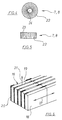
- each a side view or show a plan view of the magnetic yoke 2 the magnetic yoke 2 is off cuboid ferrite building blocks 16 composed, the surfaces of Sintered layers are freed and ground parallel to each other.
- These cuboid Ferrite building blocks 16 are again, as can be seen from FIG. 6 is, strung together, in the magnetic yoke 2 along the direction of magnetic flux 17 aligned ferrite plates 18 built.
- These ferrite plates 18 are transverse to the magnetic flux direction 17 through insulation / cooling gaps 19 separated from each other.
- plastic separators 20 are inserted in side areas, wherein the ferrite plates 18 via these plastic separators 20 to the cuboid Ferrite blocks 16 are glued as yoke elements.
- Through the insulation / cooling column 19 can be passed to cool the magnetic yoke 2 cooling air are, as is shown schematically in FIG. 6 with the arrow 21.
- the round pole pieces 7, 8 are composed of wedge-shaped ferrite building blocks 22 in plan view, the surfaces of which are also freed of sintered layers and ground plane-parallel are. Between the wedge-shaped ferrite blocks 22 are for formation insulation / cooling columns 23, also shown only schematically Separators inserted, via the adjacent ferrite modules 22 with one another are glued. The separators are in the schematic representations 4 and 5 not shown.
- pole pieces 7, 8 have an axial, tubular recess 24 through which cooling air enters the Magnetic field applicator 1 can be introduced, as can be seen in particular from FIG. 1 can be seen.
- FIG. 7 it is shown that the cuboid ferrite components 16 lie along the magnetic flux direction 17 only against one another over a very narrow contact gap (s 2 ).
- positive air gaps are advantageously used to control the magnetic flux (s 1 ) provided.
- These forced air gaps (s 1 ) have, for example, a gap width of 2 to 3 mm and are very large in comparison to the system gaps (s 2 ).
- the magnetic field is generated by the magnet coils 9, 10, which are connected to a Capacitor, which is not shown here, connected to an oscillating circuit are in which then the energy as reactive power with the resonance frequency of Circle commutes.
- the magnetic field strengths are preferably in the range of 1 to 20 kA / m, while the frequencies range preferably from 20 to 500 kHz. For a thermoseed application of the magnetic field applicator smell 1 to 2 kA / m, while for applications with magnetic liquids higher field strengths are required.
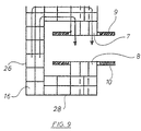
- FIG. 9 shows an alternative embodiment of a magnetic yoke 25, which has the shape of a C-arm.
- This C-arm comprises a vertical yoke part 26 and an upper transverse yoke part 27 and a lower one Transverse yoke part 28.
- the magnetic yoke 25 is basic except for the outer shape constructed with the same components as the magnetic yoke 2, so that the same Parts with the same reference numerals. So are the vertical yoke part 26 the upper transverse yoke part 27 and the lower transverse yoke part 28 cuboidal ferrite blocks 16 constructed and includes the magnetic yoke 25 pole pieces 7, 8 with these correspondingly assigned magnet coils 9, 10.
- Such a C-arm has the advantage of good accessibility, however Disadvantage that it creates a larger stray field.
Abstract
Description
Die Erfindung betrifft einen Magnetfeldapplikator zur Aufheizung von magnetischen oder magnetisierbaren Substanzen oder Festkörpern in biologischem Gewebe nach dem Oberbegriff des Anspruchs 1.The invention relates to a magnetic field applicator for heating magnetic or magnetizable substances or solids in biological Tissue according to the preamble of claim 1.
Krebserkrankungen werden in allgemein bekannter Weise durch eine chirurgische Entfernung, eine Chemotherapie, eine Bestrahlungstherapie oder eine Kombination dieser Methoden behandelt. Jede dieser Methoden unterliegt gewissen Beschränkungen: Eine operative Entfernung des Tumors ist besonders bei fortgeschrittenen Stadien, nach Metastasierung, bei Lage des Tumors in Nachbarschaft zu kritischen Körperarealen oder diffusem Tumorwachstum mit ungenauer Lokalisation nicht möglich oder bietet nur geringe Heilungschancen. Deshalb wird die chirurgische Intervention im allgemeinen kombiniert mit Strahlentherapie und Chemotherapie. Erstere kann nur so genau sein, wie die Lokalisation des Tumors durch bildgebende Verfahren unter weitestgehender Aussparung bzw. Schonung des gesunden Gewebes. Chemotherapeutische Mittel wirken dagegen systemisch, d. h. auf den ganzen Körper. Hier ist in der Regel die Knochenmarkstoxizität bzw. die Unspezifität der Therapie limitierend. Unerwünschte Nebenwirkungen sind deshalb bei allen diesen Therapieverfahren nach dem Stand der Technik unvermeidlich und schädigen in der Regel auch gesundes Gewebe. Cancers are generally known by surgical means Removal, chemotherapy, radiation therapy, or Combination of these methods is treated. Each of these methods is subject to certain Limitations: Surgical removal of the tumor is special in advanced stages, after metastasis, when the tumor is in Neighborhood to critical areas of the body or diffuse tumor growth imprecise localization is not possible or offers little chance of recovery. That is why the surgical intervention is generally combined with Radiotherapy and chemotherapy. The former can only be as accurate as that Localization of the tumor by means of imaging procedures with the greatest possible extent Recessing or protecting the healthy tissue. chemotherapeutic By contrast, agents have a systemic effect. H. on the whole body. Here is in the Rule limiting the bone marrow toxicity or the non-specificity of the therapy. Therefore, undesirable side effects are common to all of these therapy methods according to the state of the art inevitable and damage in the Usually also healthy tissue.
Als weitere Modalität hat in den letzten Jahren zunehmend die Hyperthermie an Bedeutung gewonnen, bei der das Tumorgewebe auf Temperaturen über 41°C aufgeheizt wird und so in Kombination mit Chirurgie, Strahlentherapie und Chemotherapie der Behandlungserfolg, d. h. lokale Kontrolle, z. T. sogar Überleben, verbessert werden kann. Im Temperaturbereich zwischen 41 und 46°C kommt es vom Körper unterstützt zu einem kontrollierten und eher langsamen Abbau des Tumorgewebes. Dieser Prozess wird Hyperthermie genannt, während bei höheren Temperaturen ab 47°C eine akute Zellzerstörung je nach Temperatur als Nekrose, Koagulation oder Karbonisation stattfindet und deshalb als Thermoablation bezeichnet wird. Hyperthermiesysteme nach dem Stand der Technik sind entweder nur zur vorstehend genannten Hyperthermie oder nur zur Thermoablation geeignet.Hyperthermia has become an additional modality in recent years gained importance in which the tumor tissue to temperatures above 41 ° C is heated and so in combination with surgery, radiation therapy and chemotherapy the success of treatment, d. H. local control, e.g. T. even Survival, can be improved. In the temperature range between 41 and At 46 ° C, the body supports it in a controlled and rather slow manner Breakdown of tumor tissue. This process is called hyperthermia, while at higher temperatures from 47 ° C an acute cell destruction depending on the temperature as necrosis, coagulation or carbonization takes place and is therefore called thermal ablation. Hyperthermia systems after the prior art are either only for hyperthermia mentioned above or only suitable for thermal ablation.
Ein Problem bei der Hyperthermie allgemein besteht darin, dass in der Regel keine genau lokalisierbare und vor allem homogene Erwärmung einer Zielregion des Körpers nach Stand der Technik möglich ist. Unter bestimmten physiologischen Bedingungen (z. B. Sauerstoffunterversorgung, niedriger pH) im Tumor sind zwar Krebszellen empfindlicher gegenüber Hyperthermie, jedoch trifft dies nur in wenigen Fällen zu. Hyperthermie per se ist nicht wirksamer auf Tumorzellen im Vergleich zu Normalgewebe. Deshalb ist die Begrenzung der Erwärmung auf die ärztlich indizierte Region (die nicht unbedingt nur auf die Geschwulst beschränkt sein muss) von besonderer Bedeutung und nach dem Stand der Technik nicht realisiert.One problem with hyperthermia in general is that usually no precisely localizable and above all homogeneous heating of a target region of the body is possible according to the state of the art. Under certain physiological Conditions (e.g. oxygen deficiency, low pH) in the Tumor cancer cells are more sensitive to hyperthermia, however this only applies in a few cases. Hyperthermia per se is not effective at Tumor cells compared to normal tissue. That is why the limitation of Warming up to the medically indicated region (which is not necessarily only to the Tumor must be limited) of particular importance and after State of the art not realized.
Nach dem Stand der Technik werden E-Feld dominante Systeme verwendet, die elektromagnetische Wellen in der Regel im Megahertz-Bereich von Dipol-Antennen oder anderen Antennen-Bauformen oder Antennen-Arrays abstrahlen, die zur regionalen oder lokalen Hyperthermie verwendet werden. Dabei nutzt man entweder das elektrische Feld einzelner E-Feld Applikatoren für die sogenannte interstitielle Hyperthermie oder die Interferenz von Antennen-Arrays für die Tiefenhyperthermie. Gemeinsame Schwierigkeit aller dieser E-Feld dominanten Systeme ist, dass die Leistungsabsorption nur durch die aufwendige Steuerung des E-Feldes erzielt werden kann und dass die Erwärmung abhängig ist von der elektrischen Leitfähigkeit der jeweiligen Zielgewebe, die naturgemäß sehr heterogen ist, wodurch sich eine ungleichmäßige Erwärmung auch bei homogener Abstrahlung des E-Feldes ergibt. Besonders an den Übergangsstellen von Körperregionen sehr unterschiedlicher elektrischer Leitfähigkeit kommt es deshalb zu Leistungsüberhöhungen, den sogenannten "hol spots", die zu Schmerzen und Verbrennungen des Patienten führen können. Die Folge ist eine meist vom Patienten erzwungene Reduktion der insgesamt abgegebenen Leistung, so dass dadurch auch in der Zielregion nicht die erforderliche Temperatur zur irreversiblen Schädigung des Tumorgewebes (41-42°C) erreicht wird und deshalb der Therapieerfolg ausbleibt. Durch die Interferenz von Dipol-Arrays ist außerdem nur die Erzeugung eines zweiten E-Feld Maximums in tiefergelegenen Körperarealen möglich. Die größte Leistungsabsorption findet aus physikalischen Gründen immer an der Oberfläche des Körpers, d. h. bei maximalem Radius statt. Hinzu kommt, dass sich unter Hyperthermie häufig die Durchblutung sowohl des Tumor- als auch des Normalgewebes verändert und diese Veränderung mittels E-Feld dominanter Systeme von außen aufgrund der eher geringen Steuerungsmöglichkeiten des Feldes nicht kompensiert werden kann.According to the prior art, E-field dominant systems are used the electromagnetic waves usually in the megahertz range of dipole antennas or other antenna designs or antenna arrays, used for regional or local hyperthermia. there one uses either the electric field of individual E-field applicators for the so-called interstitial hyperthermia or the interference of antenna arrays for deep hyperthermia. Common difficulty of all of these E-fields dominant systems is that the power absorption is only through the elaborate Control of the electric field can be achieved and that the warming depends on the electrical conductivity of the respective target tissue, which is naturally very heterogeneous, which results in uneven heating even with homogeneous radiation from the E-field. Especially on the Transition points of body regions of very different electrical conductivity therefore there is an increase in performance, the so-called "hol spots "that can cause pain and burns to the patient. The result is a reduction in the total that is usually forced by the patient output, so that this does not result in the required region Temperature for irreversible damage to the tumor tissue (41-42 ° C) is achieved and therefore the therapeutic success fails to materialize. Through the interference of dipole arrays is also only the generation of a second E field Maximum possible in lower body areas. The greatest power absorption always takes place on the surface of the body for physical reasons, d. H. at maximum radius instead. Add to that under hyperthermia often blood flow to both tumor and normal tissues changed and this change by means of E-field dominant systems from the outside due to the rather limited control options of the field cannot be compensated.
Weitere Verfahren nach dem Stand der Technik sind Ultraschall vorzugsweise zur Thermoablation und interstitielle Mikrowellenapplikatoren. Letztere haben aufgrund der Frequenz eine geringe Eindringtiefe und können deshalb nur in Form von interstitiellen Antennen eingesetzt werden. Darüberhinaus wird Infrarot für die Ganzkörperhyperthermie eingesetzt, sowie extrakorporale Systeme zur Aufheizung von Körperflüssigkeiten.Other methods according to the prior art are preferably ultrasound for thermal ablation and interstitial microwave applicators. The latter have due to the frequency a small depth of penetration and can therefore only in Form of interstitial antennas can be used. In addition, infrared used for whole body hyperthermia, as well as extracorporeal systems for heating up body fluids.
Weiter ist ein Hyperthermieverfahren zur Therapie von Prostatakrebs bekannt (US 5 197 940), bei dem im Tumorbereich "Thermoseeds" eingebracht sind, die aus magnetischem, insbesondere ferromagnetischem oder aus magnetisierbarem Material bestehen oder ein solches enthalten. Diese Thermoseeds haben eine typische Größe von mehreren Zentimetern Länge und einen Durchmesser im Millimeterbereich. Ersichtlich ist es erforderlich, solche Thermoseeds in aufwendiger Weise chirurgisch zu implantieren. Diese Thermoseeds werden bei einer Behandlung mit einem außerhalb eines Patienten erzeugten Magnetwechselfeld beaufschlagt, wobei durch an sich bekannte Hystereseeffekte Wärme in den Thermoseeds als Hyperthermie entsteht.A hyperthermia method for the treatment of prostate cancer is also known (US 5 197 940), in which "thermoseeds" are introduced in the tumor area, those made of magnetic, in particular ferromagnetic or made of magnetizable Exist or contain material. These thermoseeds have a typical size of several centimeters in length and one Diameter in the millimeter range. Obviously, such thermoseeds are required to implant surgically in a complex manner. These thermoseeds are generated during treatment with a patient outside of a patient Magnetic alternating field applied, whereby by known Hysteresis effects Heat arises in the thermoseeds as hyperthermia.
Die Erwärmung solcher Seeds geschieht allerdings nach dem Prinzip der "heißen Quellen", d. h. während sich die Seeds aufheizen, fällt die Temperaturen in der Umgebung des Seeds exponentiell ab, so dass in der klinischen Anwendung der Abstand zwischen den Seeds nicht größer als 1 cm sein darf. Bei größeren oder ungleichmäßigen Abständen entsteht eine thermische Unterdosierung, die ebenfalls den Therapieerfolg verhindern kann. Gerade bei größeren Tumoren entsteht so die Notwendigkeit einer sehr engen Implantation der Seeds, wodurch die Methode chirurgisch aufwendig und für den Patienten belastend ist. Abgesehen vom geringen Abstand müssen die Seeds auch für optimale Leistungsaufnahme parallel zum magnetischen Wechselfeld ausgerichtet sein. Eine Überhitzung wird durch die Curie-Temperatur bei sogenannten selbstregulierenden Thermoseeds verhindert, bei denen nach Erreichen der Curie-Temperatur das Ferrit in einen nicht-magnetisierbaren Zustand übergeht und dann keine weitere Leistungsaufnahme mehr erfolgt.Such seeds are heated according to the principle of "hot springs", i.e. H. As the seeds heat up, the temperatures drop around the seed exponentially, so in clinical Application the distance between the seeds must not be greater than 1 cm. With larger or uneven distances there is a thermal underdosing, which can also prevent therapy success. Especially with Larger tumors thus need very tight implantation the seeds, making the method surgically complex and patient-friendly is stressful. Apart from the short distance, the seeds also for optimal power consumption parallel to the alternating magnetic field be aligned. Overheating is caused by the so-called Curie temperature Prevents self-regulating thermoseeds at which after reaching the Curie temperature the ferrite into a non-magnetizable state passes over and then no further power consumption takes place.
Als Magnetfeldapplikator für das Magnetwechselfeld ist hier eine Magnetspule eines Schwingkreises verwendet, in derem Achsbereich die Körperregion eines Patienten mit den implantieren Thermoseeds einbringbar ist. Konkret sind hier Luftspulen verwendet, in deren mittleren Bereichen ein Patient bei einer Behandlung auf einer nicht magnetisierbaren Abstützplatte sitzt.Here is a magnetic coil as a magnetic field applicator for the alternating magnetic field of a resonant circuit, the body region in its axis area a patient can be inserted with the implanted thermoseeds. Concrete air coils are used here, in the middle areas of a patient treatment sits on a non-magnetizable support plate.
Nachteilig an der interstitiellen Hyperthermie mit Thermoseeds ist der hohe chirurgische Aufwand und die hohe Invasivität der Methode, das Risiko einer nicht exakten Ausrichtung oder Positionsänderung der Seeds und dem damit verbundenen Risiko thermischer Unterdosierung sowie eine Begrenzung der Methode auf Tumore kleinerer Ausdehnung.The disadvantage of interstitial hyperthermia with thermoseeds is the high one surgical effort and the high invasiveness of the method, the risk of not exact alignment or position change of the seeds and with that associated risk of thermal underdosing and a limitation of Small-scale tumor method.
Bei einem weiteren bekannten Hyperthermieverfahren (WO 97/43005) zur Tumortherapie werden magnetisierbare Mikrokapseln vorgeschlagen, die durch den Blutstrom in den Tumorbereich gelangen. Damit sollen unter anderem chirurgische Implantationen von magnetisierbaren Elementen vermieden werden, da bei Implantationen neben den Beschwernissen für einen Patienten auch die Gefahr besteht, dass bei einem Schnitt in den Tumor entartete Tumorzellen in gesundes Gewebe streuen. Zur Befeldung wird ein lineares Magnetwechselfeld verwendet mit einer Frequenz im Bereich zwischen 10 kHz bis 500 kHz. Die Mikrokapseln sollen in Verbindung mit einem hochmagnetisierbaren Material verwendet werden, so dass die für die Befeldung erforderliche Stärke des Magnetwechselfeldes hinsichtlich des apparativen Aufbaus der erforderlichen Kühlsysteme sowie der elektrischen Energieversorgung beherrschbar werden. Ein konkreter apparativer Aufbau ist jedoch nicht angegeben.In another known hyperthermia method (WO 97/43005) for Tumor therapy suggests magnetizable microcapsules through the bloodstream into the tumor area. Among other things surgical implantations of magnetizable elements avoided because in addition to the complications for a patient there is also the danger that tumor cells degenerate when cut into the tumor sprinkle in healthy tissue. A linear Alternating magnetic field used with a frequency in the range between 10 kHz up to 500 kHz. The microcapsules are said to be in connection with a highly magnetizable Material used so that the necessary for the exposure Strength of the alternating magnetic field with regard to the construction of the apparatus required cooling systems and the electrical power supply can be controlled become. However, no specific apparatus structure is given.
In einem weitgehend ähnlichen bekannten Hyperthermieverfahren (EP 0 913 167 A2) werden zur Befeldung rotierende Magnetfelder mit einer Frequenz im Bereich größer 10 kHz verwendet. Zur Erzeugung des hier verwendeten rotierenden Magnetwechselfeldes ist lediglich skizzenhaft und schematisch ein gattungsgemäßer Magnetfeldapplikator angegeben. Der Magnetfeldapplikator umfasst ein Magnetjoch mit jeweils zwei gegenüberliegenden, durch einen Befeldungsspalt beabstandeten Polschuhen und zwei jeweils diesen Polschuhen zugeordneten Magnetspulen. Konkret ist ein rechteckiges Magnetjoch gezeigt, bei dem ausgehend von der Mitte jedes Jochschenkels ein Polschuh auf die Mitte des Rechtecks zugerichtet ist, wodurch dort ein Befeldungsraum gebildet wird. An den Polschuhen sind Zylinderspulen angebracht, die jeweils gegenüberliegend miteinander und mit einer zugeordneten Kondensatoranordnung zu einem Schwingkreis verbunden sind.In a largely similar known hyperthermia procedure (EP 0 913 167 A2) rotating magnetic fields with a Frequency used in the range greater than 10 kHz. To generate the used here rotating alternating magnetic field is merely sketchy and schematically indicated a generic magnetic field applicator. The Magnetic field applicator comprises a magnetic yoke, each with two opposite, pole shoes spaced apart by an exposure gap and two magnet coils assigned to each of these pole pieces. Specifically, it is rectangular Magnetic yoke shown, starting from the center of each yoke leg a pole piece is aimed at the center of the rectangle, thereby an exposure area is formed there. There are solenoids on the pole pieces attached, each opposite to each other and with an associated Capacitor arrangement are connected to an oscillating circuit.
Diese schematische Darstellung eines Magnetfeldapplikators zur Durchführung des vorstehenden Hyperthermieverfahrens führt noch zu keiner, über ein Experimentierstadion hinausgehenden konstruktiven Serienlösung, wie sie hinsichtlich günstiger Herstellungs- und Betriebskosten, eines geringen Einbauraums mit geringer Streufeldbelastung und eines optimalen therapeutischen Effekts zur Verwendung im Krankenhausbetrieb erforderlich ist.This schematic representation of a magnetic field applicator for implementation the above hyperthermia procedure does not lead to any, via an experimental stadium constructive series solution going beyond that as regards Favorable manufacturing and operating costs, a small installation space with low stray field pollution and an optimal therapeutic Effect for hospital use is required.
Aufgabe der Erfindung ist es daher, einen Magnetfeldapplikator zur Aufheizung von magnetischen oder magnetisierbaren Substanzen oder Festkörpern in biologischem Gewebe zu schaffen, der die vorstehenden Forderungen hinsichtlich einer Serienlösung für den Krankenhausbetrieb oder eines anderweitigen, ggf. industriellen Einsatzes erfüllt.The object of the invention is therefore a magnetic field applicator for heating of magnetic or magnetizable substances or solids in to create biological tissue that meets the above requirements regarding a series solution for hospital operation or another, possibly industrial use.
Diese Aufgabe wird mit den Merkmalen des Anspruchs 1 gelöst.This object is achieved with the features of claim 1.
Gemäß Anspruch 1 bestehen das Magnetjoch und die Polschuhe aus zusammengesetzten und zusammenmontierten Ferritbausteinen. Die Magnetspulen sind Scheibenspulen mit wenigstens einer schneckenförmig verlaufenden Windung, die jeweils einem Polschuh zugeordnet sind und das jeweilige Polschuhende mit einem dazwischenliegenden, umlaufenden Magnetspule/Polschuh-Spalt umfassen.According to claim 1, the magnetic yoke and the pole shoes consist of composite and assembled ferrite components. The solenoids are disc coils with at least one helical Turn, which are each assigned to a pole piece and the respective pole piece end with a circumferential magnetic coil / pole shoe gap in between include.
Für die Hyperthermie, insbesondere mit magnetischen Flüssigkeiten, werden Wechselfeldstärken von ca. 15 bis 20 kA/m bei ca. 50 bis 100 kHz benötigt. Bei einem Befeldungsvolumen von 8 bis 30 l sind dabei von einer Hyperthermieanlage Wirkleistungen von ca. 18 kW bis 80 kW aufzubringen. Diese Energie muss als Hochfrequenz erzeugt werden und dann als Wärme wieder abgeführt werden, da für die Hyperthermie im Körper eines Patienten nur einige Watt in der magnetischen Flüssigkeit entstehen. For hyperthermia, especially with magnetic fluids Alternating field strengths of approx. 15 to 20 kA / m at approx. 50 to 100 kHz are required. With a radiation volume of 8 to 30 l are from a hyperthermic system To apply active powers from approx. 18 kW to 80 kW. That energy must be generated as a high frequency and then dissipated as heat because there are only a few for hyperthermia in a patient's body Watts arise in the magnetic fluid.
Mit der im Patentanspruch 1 beanspruchten Anordnung ist es möglich, das befeldete Volumen sowie Streufelder vorteilhaft klein zu halten und weitgehend auf einen zu therapierenden Bereich im Körper eines Patienten zu begrenzen, so dass der erforderliche Energieaufwand und Aufwand für den Wärmetransport reduzierbar ist. Dazu tragen insbesondere ein Magnetjoch und Polschuhe aus Ferritbausteinen sowie die Scheibenspule mit wenigstens einer schneckenförmigen Windung bei. Durch die spezielle Ausgestaltung der Magnetspulen in Verbindung mit dem umlaufenden Magnetspule/Polschuh-Spalt werden unerwünschte Überhöhungen der Flussdichten in Verbindung mit großen Verlusten wesentlich reduziert. Im Vergleich mit der vorgeschlagenen Anordnung treten beispielsweise bei der im Stand der Technik angegebenen Anordnung mit Zylinderspulen um die Polschuhe in deren letzter Windung zum Befeldungsspalt durch induktive Erwärmung hohe Temperaturen mit erheblichen Problemen bei einer Wärmeabfuhr auf. Die erfindungsgemäße, scheibenförmige Spulenausführung in Verbindung mit dem Magnetspule/Polschuh-Spalt führt dagegen zu wesentlichen geringeren Flussdichten auf der umlaufenden Kante der jeweils zugeordneten Polschuhe.With the arrangement claimed in claim 1, it is possible that Exposed volumes and stray fields are advantageously kept small and largely limited to an area to be treated in a patient's body, so that the required energy and effort for heat transport is reducible. In addition, wear a magnetic yoke and pole shoes made of ferrite components and the disc coil with at least one helical turn. Due to the special design of the Solenoid coils in connection with the circumferential solenoid coil / pole shoe gap are associated with undesirable increases in flux densities large losses significantly reduced. Compared to the proposed one Arrangement occur, for example, in the one specified in the prior art Arrangement with solenoids around the pole shoes in their last turn Exposure gap due to inductive heating high temperatures with considerable Problems with heat dissipation. The disc-shaped according to the invention Coil version in connection with the magnet coil / pole shoe gap leads, however, to significantly lower flux densities on the orbiting Edge of the respectively assigned pole shoes.
Die Verwendung von Ferritbausteinen ermöglicht in Verbindung mit der hohen Wechselfrequenz von ca. 50 bis 100 kHz eine vorteilhafte Begrenzung des Befeldungsvolumens, wobei im Ferritvolumen etwa nur 1/2000 der Energie bewegt wird, die ein äquivalentes Luftvolumen hätte. Diesem erheblichen Vorteil steht gegenüber, dass die Ferritbausteine jedoch verlustbehaftet sind, wobei z. B. eine Verdopplung der Flussdichte im Arbeitsbereich bereits 5 bis 6-fache Verluste bringen kann. Es werden daher nachstehend geeignete Maßnahmen angegeben, um die Flussdichten klein zu halten und insbesondere unerwünschte Flussdichteerhöhungen zu vermeiden oder wenigstens stark zu reduzieren.The use of ferrite blocks in conjunction with the high AC frequency of about 50 to 100 kHz an advantageous limitation of Radiation volume, with only about 1/2000 of the energy in the ferrite volume is moved, which would have an equivalent volume of air. This significant advantage stands in contrast to the fact that the ferrite modules are lossy, whereby z. B. a doubling of the flux density in the work area already 5 to Can bring 6 times losses. Appropriate measures are therefore described below specified to keep the flux densities low and in particular to avoid undesirable increases in flux density or at least strongly to to reduce.
Ferrite sind keramikartige Bausteine, die sich nicht in beliebigen Gestalten mit vertretbarem Aufwand herstellen lassen, insbesondere nicht in der Gesamtgestalt des hier verwendeten Magnetjochs. Daher wird erfindungsgemäß vorgeschlagen, das Magnetjoch aus Ferritbausteinen zusammenzusetzen, wobei an den Übergangsstellen Störungen eines möglichst gleichmäßigen Flussverlaufes auftreten können. Vorteilhafte Lösungen zur Beherrschung dieser Probleme sind weiter unten angegeben.Ferrites are ceramic-like building blocks that cannot be found in any shape allow reasonable effort to be made, especially not in the overall form of the magnetic yoke used here. It is therefore proposed according to the invention assemble the magnetic yoke from ferrite building blocks, whereby at the transition points disruption of a flow as even as possible may occur. Advantageous solutions to master these problems are given below.
Der erfindungsgemäße Magnetfeldapplikator ist gleichermaßen geeignet sowohl für die Durchführung von Hyperthermien als auch für Thermoablationsverfahren. Darüberhinaus ist der erfindungsgemäße Magnetfeldapplikator geeignet zur Erwärmung auch anderer Substanzen oder Festkörper für medizinische Anwendungen außerhalb der Krebstherapie. Unter letzteren werden alle erwärmungsbedingten medizinischen Anwendungen verstanden, wie z. B. wärmeinduzierte Implantat- bzw. Stentregenerierung, Implantat- bzw. Stentoberflächenaktivierung, Aufheizung von nicht durch Krebs erkrankten bzw. entzündlichen Körperregionen zu Therapiezwecken, die erleichtere Konstrastmittelverteilung oder -verbesserung mittels Magnetwechselfeldanregung superparamagnetischer Kontrastmittel, das Einschalten molekularbiologischer, zellbiologischer und entwicklungsphysiologischer Vorgänge mittels Anregung Magnetcarriergestützter Gentransfersysteme, Liganden, Rezeptoren, Transmittern, sonstigen Signalmolekülen sowie die Auslösung von Stoffwechselvorgängen und endokrinen Prozessen.The magnetic field applicator according to the invention is equally suitable for the implementation of hyperthermia as well as for thermal ablation procedures. The magnetic field applicator according to the invention is also suitable for heating other substances or solids for medical purposes Applications outside of cancer therapy. Under the latter are all heat-related medical applications understood such. B. heat-induced implant or stent regeneration, implant or stent surface activation, Heating of cancer patients inflammatory body regions for therapeutic purposes, the easier distribution of contrast agents or improvement by means of superparamagnetic alternating magnetic field excitation Contrast agent, switching on molecular biological, cell biological and developmental physiological processes by means of stimulation Magnetic carrier-assisted gene transfer systems, ligands, receptors, transmitters, other signaling molecules and the triggering of metabolic processes and endocrine processes.
In einer konkreten Ausführungsform nach Anspruch 2 sollen die Magnetspulen eine oder mehrere Windungen aufweisen, die schneckenförmig verlaufen und aus verseilten Kupfer-Litzendrähten hergestellt sein, um Wirbelstromverluste möglichst klein zu halten.In a specific embodiment according to claim 2, the solenoids should have one or more turns that are helical and be made of stranded copper stranded wire to avoid eddy current losses to keep it as small as possible.
In einer besonders vorteilhaften Ausbildung werden nach Anspruch 3 die Polschuhe
zylindrisch bzw. in einer Draufsicht kreisrund ausgeführt, wobei sie mit
gegeneinanderweisenden, parallel ausgerichteten Polschuhkreisflächen im
Abstand des Befeldungsspalts gegenüberliegen. Entsprechend sind dann die
Magnetspulen kreisringförmig ausgebildet. Dies führt zu einer Vergleichmäßigung
des Magnetflusses mit einer Reduzierung von Erwärmungen, die ansonsten
an räumlichen Ecken und Kanten erhöht auftreten würden.In a particularly advantageous embodiment, the pole pieces according to
Energetisch und flusstechnisch besonders günstige Verhältnisse ergeben sich nach Anspruch 4, wenn die scheibenförmige Magnetspule möglichst nahe am Befeldungsspalt angeordnet ist, insbesondere in einer flächenbündigen Anordnung bezüglich der jeweils zugeordneten Polschuhendfläche. Eine weitere Optimierung wird erreicht, wenn dabei der Magnetspule/Polschuh-Spalt in einer Größe von etwa 1/10 des Polschuhdurchmessers (0,07 bis 0,1-fach) liegt und die umlaufende Kante der jeweiligen Polschuhendfläche abgerundet ist. Damit werden schädliche Flussdichteüberhöhungen stark reduziert.The conditions are particularly favorable in terms of energy and flow technology according to claim 4, if the disc-shaped magnet coil as close as possible to The exposure slit is arranged, in particular in a flush arrangement with regard to the respectively assigned pole shoe end surface. Another optimization is achieved if the solenoid / pole shoe gap in one Size of about 1/10 of the pole piece diameter (0.07 to 0.1 times) and the peripheral edge of the respective pole shoe end surface is rounded. In order to harmful increases in flux density are greatly reduced.
Gemäß Anspruch 5 soll der Polschuhdurchmesser größer als die Befeldungsspaltweite
sein. Dadurch werden Streufelder außerhalb der Polschuhe bzw.
des Befeidungsvolumens reduziert, wodurch die Flussdichte in den Ferritbausteinen
und damit die Verluste im Ferritmaterial relativ klein gehalten werden
können. Bei Polschuhen mit relativ kleinem Querschnitt würden diese Verluste
in den Ferritbausteinen überproportional steigen.According to
Gemäß Anspruch 6 ist das Magnetjoch aus quaderförmigen Ferritbausteien
zusammengesetzt, deren Flächen zur Schaffung gleichmäßiger Übergänge
plan-parallel geschliffen sind, wobei ggf. äußere Sinterschichten entfernt sind.
Entsprechend sind die runden Polschuhe aus keilförmigen Ferritbausteinen
wie aus Tortenstücken zusammengesetzt, wobei auch hier benachbarte Flächen
plan-parallel geschliffen sind.According to
Zur Senkung der Wirbelstromverluste wird mit Anspruch 7 vorgeschlagen, die
quaderförmigen Ferritbausteine aus aneinandergereihten Ferritplatten herzustellen
und jeweils durch Isolations/Kühlungs-Spalte beabstandet zu halten. Im
montierten Zustand sind diese Ferritplatten längs des Magnetflusses ausgerichtet.
Zur Herstellung einstückiger Ferritbausteine aus den Ferritplatten werden
diese nach Anspruch 8 mittels Separatoren aus Kunststoff auf Abstand
gehalten und miteinander über die Separatoren verklebt.To reduce the eddy current losses is proposed with
Ähnlich werden nach Anspruch 9 die keilförmigen Ferritbausteine zur Bildung
der Polschuhe hergestellt, wobei eine rohrförmige mittlere Aussparung offengelassen
wird, durch die Kühlluft einleitbar ist. Zur Verklebung der Ferritplatten
wird vorzugsweise ein temperaturbeständiger, Zwei-Komponenten-Klebstoff
verwendet.Similarly, according to
Die Spalte zwischen den Ferritplatten dienen sowohl der elektrischen Isolation als auch der Kühlung, indem durch die Spalte Kühlluft geblasen wird. Die Kühlung ist erforderlich, da trotz geringer Leitfähigkeit der Ferrite relativ große Wirbelströme entstehen und die dadurch erzeugte Wärme abgeführt werden muss. Eine Flüssigkeitskühlung wäre zwar effektiver, ist aber wegen der Isolationsforderungen nicht realisierbar. Eine Ölkühlung ist wegen der Brennbarkeit von Ölen mit Gefahren verbunden und vergleichbare nichtbrennbare Flüssigkeiten enthalten regelmäßig Giftstoffe. Allgemein wäre bei einer Flüssigkeitskühlung das Dichtproblem insbesondere bei einem beweglichen Jochteil in Verbindung mit den übrigen technischen Schwierigkeiten nur mit hohem Aufwand lösbar.The gaps between the ferrite plates serve both for electrical insulation as well as the cooling by blowing cooling air through the column. The Cooling is necessary because, despite the low conductivity of the ferrites, they are relatively large Eddy currents arise and the heat generated is dissipated got to. Liquid cooling would be more effective, but is because of the insulation requirements not feasible. Oil cooling is because of the flammability of oils associated with dangers and comparable non-flammable liquids regularly contain toxins. General would be with liquid cooling the sealing problem in particular with a movable yoke part in Connection with the other technical difficulties only with great effort solvable.
In einer bevorzugten Ausführungsform nach Anspruch 10 besteht das Magnetjoch
aus wenigstens einem Vertikaljochteil und zwei daran angeschlossenen
Querjochteilen, wobei an den Querjochteilen die gegeneinandergerichteten
Polschuhe angeschlossen sind. Wenigstens ein Querjochteil ist relativ gegenüber
dem anderen Querjochteil zur Veränderung der Befeldungsspaltweite
verstellbar. Wie bereits ausgeführt, soll für insgesamt günstige Verhältnisse
das befeldete Volumen so klein wie irgend möglich gehalten werden. Dies
kann bei der verlagerbaren Querjochteilausführung dadurch erzielt werden,
dass zur bequemen Einbringung, z. B. eines Patienten, in den Befeldungsspalt
der Polschuhabstand durch Verlagerung wenigstens eines Querjochteils vergrößert
und anschließend für die Befeldung wieder so weit wie möglich verkleinert
wird.In a preferred embodiment according to
Einerseits wird, wie weiter oben angegeben, der Magnetfluss an Übergangsstellen dadurch gesteuert, dass einerseits herstellungsbedingte, magnetisch inaktive Sinterschichten von etwa 0,1 bis 0,2 mm entfernt werden und zudem magnetisch leitende Fläche plan-parallel geschliffen werden. Wegen der hohen Ferrit-Permeabilität wirken sich kleinste Unebenheiten aus, so dass eine Flusssteuerung mit Zwangsluftspalten gemäß Anspruch 11 zweckmäßig ist. Insbesondere ist dies mit Zwangsspalten von 2 bis 3 mm an den Übergangsstellen zwischen den beweglichen Querjochteilen und angrenzenden Vertikaljochteilen und/oder an Übergangsstellen zwischen Querjochteilen und den Polschuhen vorteilhaft. Im Bereich solcher relativ breiter Zwangsspalte kann je nach den Gegebenheiten eine Sinterschicht zur Reduzierung der Herstellungskosten ein einem Ferritbaustein verbleiben.On the one hand, as stated above, the magnetic flux at transition points controlled by the fact that, on the one hand, production-related, magnetic inactive sintered layers of about 0.1 to 0.2 mm can be removed and also magnetically conductive surface can be ground plane-parallel. Because of the high Ferrite permeability affects the smallest bumps, so that one Flow control with forced air gaps according to claim 11 is appropriate. This is particularly the case with forced gaps of 2 to 3 mm at the transition points between the movable cross-yoke parts and adjacent vertical yoke parts and / or at transition points between transverse yoke parts and Pole shoes advantageous. In the area of such a relatively wide compulsory gap can ever Depending on the circumstances, a sintered layer to reduce manufacturing costs remain in a ferrite block.
Grundsätzlich kann nach Anspruch 12 das Magnetjoch als C-Bogen ausgeführt sein, bei dem der Bereich der C-Öffnung den durch die Polschuhe gebildeten Befeldungsspalt darstellt. Vorteilhaft ist hier die gute Zugänglichkeit der Polschuhe und der Magnetspulen und damit des gesamten Befeldungsspalts. Allerdings treten bei einem C-Bogen relativ große Streufelder auf und für den Magnetrückschluss unterschiedlich lange Flusswege sowie Umleitungsprobleme an den Ecken.Basically, the magnetic yoke can be designed as a C-arm in which the area of the C opening is that formed by the pole pieces Represents exposure gap. The good accessibility of the pole shoes is advantageous here and the magnetic coils and thus the entire exposure gap. Indeed Relatively large stray fields occur with a C-arm and for the Magnetic inference of flow paths of different lengths and diversion problems at the corners.
Eine besonders bevorzugte Ausführungsform nach Anspruch 13 weist dagegen
ein Magnetjoch in einer M-Form als Drei-Schenkel-Anordnung auf mit zwei
beabstandeten, parallelen Vertikaljochteilen gleicher Geometrie und mit zwei
dazwischen angeschlossenen Querjochteilen, an denen im mittleren Bereich
die aufeinander zugerichteten Polschuhe mit den Magnetspulen angeordnet
sind. Ein Querjochteil mit zugeordneter Magnetspule ist als Baueinheit relativ
zum anderen Querjochteil zur Einstellung der Befeldungsspaltweite verstellbar
ausgeführt. Vorteilhaft wird hier der magnetische Rückschluss zu beiden Seiten
auf zwei gleich lange Wege aufgeteilt, die die gleiche Geometrie haben.
Die Mechanik für die Relativerstellung wenigstens eines Querjochteils ist gegenüber
einem C-Magnetjoch einfacher ausführbar, da die Vertikaljochteile als
beidseitige Abstützungen nützbar sind.A particularly preferred embodiment according to
Dazu wird nach Anspruch 14 eine Baueinheit aus einem unteren Querjochteil
und dem zugeordneten Polschuh mit Magnetspule ortsfest angebracht. Auf
diesem ortsfesten Polschuh kann dann beispielsweise ein Patientenschlitten
mit Patientenlager und Schlittenpositionsanzeige aus Kunststoffmaterial angebracht
werden, wobei dann der Patient bei einer Einstellung der Befeldungsspaltweite
nicht mehr bewegt werden muss. Gegenüber dieser ortsfesten Baueinheit
ist dann ein Portal aus den beiden Vertikaljochteilen aus dem oberen
Querjochteil mit dem zugeordneten Polschuh mit Magnetspule mittels einer
Vertikalverstelleinrichtung zur Einstellung der Befeldungspaltweite verstellbar.For this purpose, according to
Eine Vertikalverstelleinrichtung kann nach Anspruch 15 als einfacher Linearantrieb ausgeführt werden, der vorzugsweise jeweils an einem Vertikalmagnetjochteil angreift. Beispielsweise kann ein selbsthemmender Spindeltrieb eingesetzt werden, wodurch die Gesamtanordnung sehr sicher ausführbar ist ohne die Gefahr, dass schwere Magnetjochbauteile durch Fehler in der Verstelleinrichtung zu einer Gefährdung eines Patienten führen.A vertical adjustment device can according to claim 15 as a simple linear drive are carried out, each preferably on a vertical magnetic yoke part attacks. For example, a self-locking spindle drive are used, whereby the overall arrangement can be carried out very safely without the risk of heavy magnetic yoke components due to errors in the adjustment device endanger a patient.
In einer vorteilhaften Weiterbildung nach Anspruch 16 kann das Magnetjoch in
einer Tragkonstruktion gehalten sein, in der zudem Kühlluft zuführbar und leitbar
ist, welche dann die Kühlluftspalte der Ferritbausteine zur Wärmeabfuhr
durchströmt.In an advantageous development according to
Je nach den Gegebenheiten und den speziellen Erfordernissen kann nach Anspruch
17 der Befeldungsspalt und damit das Befeldungsvolumen seitlich
durch Feldbegrenzungsspulen und/oder durch Schottwände begrenzt sein.Depending on the circumstances and the special requirements can be according to
Grundsätzlich kann der erfindungsgemäße Magnetfeldapplikator für eine genau
lokalisierte und berührungsfreie Hyperthermie an allen möglichen zu befeldenden
Geweben, Körpern, Gegenständen und Massen unter Verwendung
eingebrachter magnetischer und/oder magnetisierbarer Substanzen zu geeigneten
Zwecken verwendet werden. Eine bevorzugte Anwendung des Magnetfeldapplikators
liegt nach Anspruch 18 jedoch im medizinischen Bereich, insbesondere
in der Krebstherapie, wobei vorzugsweise als Substanz eine magnetisierbare
Flüssigkeit mit magnetisierbaren Nanoteilchen verwendet ist. Ein
Tumorbereich soll damit auf Temperaturwerte über ca. 41°C lokal erhitzbar
sein.In principle, the magnetic field applicator according to the invention can be used for one
localized and non-contact hyperthermia in all possible fields
Using tissues, bodies, objects and masses
introduced magnetic and / or magnetizable substances to suitable
Be used for purposes. A preferred application of the magnetic field applicator
However, according to
Nach Anspruch 19 werden dazu Magnetwechselfelder mit Magnetfeldstärken
von ca. 10 bis 15 kA/m und Frequenzen von ca. 50 bis 100 kHz eingesetzt. In
Verbindung mit dem vorstehend beanspruchten Magnetfeldapplikator werden
dann die erforderlichen Temperaturen für eine Tumortherapie erreicht. Für
eine Thermoseed-Anwendung des Magnetfeldapplikators reichen bereits 1 bis
2 kA/m aus. Je nach den vorliegenden Gegebenheiten können auch Frequenzen
in einem weiteren Frequenzbereich von 20 bis 500 kHz geeignet sein.According to
Anhand einer Zeichnung wird die Erfindung näher erläutert.The invention is explained in more detail with reference to a drawing.
Es zeigen:
- Fig. 1
- eine schematische Schnittansicht durch einen Magnetfeldapplikator,
- Fig. 2
- eine schematische Draufsicht auf den Magnetfeldapplikator der Fig. 1,
- Fig. 3
- eine schematische Seitenansicht des Magnetfeldapplikators der Fig. 1,
- Fig. 4
- eine Draufsicht auf einen Polschuh mit keilförmigen Ferritbausteinen,
- Fig. 5
- eine Seitenansicht des Polschuh der Fig. 4,
- Fig. 6
- eine schematische, perspektivische und vergrößerte Darstellung des Aufbaus quaderförmiger Ferritbausteine,
- Fig. 7
- eine schematische und vergrößerte Darstellung eines Übergangsbereiches zwischen einem Vertikaljochteil und einem Querjochteil,
- Fig. 8
- eine schematische Seitenansicht einer flächenbündig mit einer Polschuhendfläche angeordneten Magnetspule, und
- Fig. 9
- eine schematische Ansicht eines alternativen Magnetfeldapplikators in der Form eines C-Bogens.
- Fig. 1
- 1 shows a schematic sectional view through a magnetic field applicator,
- Fig. 2
- 2 shows a schematic top view of the magnetic field applicator of FIG. 1,
- Fig. 3
- 2 shows a schematic side view of the magnetic field applicator of FIG. 1,
- Fig. 4
- a plan view of a pole piece with wedge-shaped ferrite building blocks,
- Fig. 5
- 3 shows a side view of the pole piece of FIG. 4,
- Fig. 6
- 1 shows a schematic, perspective and enlarged representation of the structure of cuboid ferrite modules,
- Fig. 7
- 1 shows a schematic and enlarged illustration of a transition region between a vertical yoke part and a transverse yoke part,
- Fig. 8
- is a schematic side view of a magnet coil arranged flush with a pole shoe end face, and
- Fig. 9
- a schematic view of an alternative magnetic field applicator in the form of a C-arm.
In der Fig. 1 ist schematisch ein Magnetfeldapplikator 1 für die Hyperthermie dargestellt, in den ein zu befeldender Körper, in den eine magnetische oder magnetisierbare Substanz oder Festkörper einbringbar ist, bestrahlbar ist. Als zu befeldender Körper eignet sich insbesondere ein Tumorbereich in einem menschlichen Körper, in dem eine Flüssigkeit mit z. B. magnetischen Nanoteilchen eingebracht ist, wobei der Tumorbereich auf Temperaturwerte vorzugsweise von über ca. 41°C erhitzbar ist.1 schematically shows a magnetic field applicator 1 for hyperthermia shown in which a body to be fielded, in which a magnetic or magnetizable substance or solid can be introduced, can be irradiated. As a tumor area in one is particularly suitable human body in which a liquid with z. B. magnetic nanoparticles is introduced, the tumor area preferably at temperature values can be heated above about 41 ° C.
Der Magnetfeldapplikator 1 umfasst ein Magnetjoch 2, das in einer M-Form als
Drei-Schenkel-Anordnung ausgebildet ist und zwei beabstandete, parallele
Vertikaljochteile 3, 4 sowie zwei dazwischen angeschlossene Querjochteile 5,
6 aufweist.The magnetic field applicator 1 comprises a magnetic yoke 2 which is in an M-shape
Three-leg arrangement is formed and two spaced, parallel
Eine Baueinheit aus unterem Querjochteil 6 und diesem zugeordneten unteren
Polschuh 8 mit unterer Magnetspule 10 ist ortsfest angebracht. Demgegenüber
kann ein Portal aus den beiden Vertikaljochteilen 3, 4, dem angeschlossenen
oberen Querjochteil 5 sowie diesem zugeordneten oberen Polschuh 7 mit oberer
Magnetspule 9 mittels eines hier lediglich schematisch dargestellten,
selbsthemmenden Spindelantriebs 11 zur Einstellung der Befeldungsspaltweite
des Befeldungsspaltes 12 verstellt werden.A unit from the lower
Der Fig. 1 kann weiter entnommen werden, dass der Befeldungsspalt 12 durch
Schottwände 14, 15 begrenzt ist, die einen Einschubraum 13 umgrenzen. Die
Schottwände 14, 15 können dabei gegeneinander vertikal verstellbar sein.1 can further be seen that the
Wie dies insbesondere auch aus der Fig. 8 ersichtlich ist, sind die obere Magnetspule
9 und die untere Magnetspule 10 als Scheibenspulen ausgebildet mit
einer oder mehreren Windungen, die schneckenförmig verlaufen und aus verseilten
Kupfer-Litzendrähten hergestellt sind.As can be seen in particular from FIG. 8, the
Der Fig. 8 ist ferner zu entnehmen, dass die Magnetspulen 9, 10 die Polschuhenden
mit einem dazwischenliegenden und umlaufenden Magnetspule/Polschuh-Spalt
(a) umfassen. Wie dies insbesondere aus der Fig. 4 ersichtlich
ist, die eine Draufsicht auf einen der Polschuhe 7, 8 zeigt, sind die Polschuhe
7, 8 kreisrund ausgebildet. Der Magnetspule/Polschuh-Spalt (a) liegt in
einem Größenbereich von 0,07 bis 0,1 mal dem Polschuhdurchmesser (d),
wobei die Magnetspule in etwa flächenbündig mit der Polschuhendfläche angeordnet
ist und die umlaufende Kante an der Polschuhendfläche abgerundet
ist.8 also shows that the magnet coils 9, 10 are the pole shoe ends
with a magnetic coil / pole shoe gap in between and rotating
(a) include. As can be seen in particular from FIG. 4
which shows a plan view of one of the
Des weiteren wird in Abhängigkeit vom Polschuhdurchmesser (d) auch die
Größe des Befeldungsspaltes 12 ausgelegt, um die Streufelder zu reduzieren.
So ist in einer bevorzugten Ausführungsform zur Vermeidung von Streufeldern
der Polschuhdurchmesser (d) größer als der Befeldungsspalt 12. Furthermore, depending on the pole piece diameter (d)
Size of the
Wie dies aus den Fig. 2 und 3 ersichtlich ist, die jeweils eine Seitenansicht
bzw. eine Draufsicht auf das Magnetjoch 2 zeigen, ist das Magnetjoch 2 aus
quaderförmigen Ferritbausteinen 16 zusammengesetzt, deren Oberflächen von
Sinterschichten befreit und jeweils plan-parallel geschliffen sind. Diese quaderförmigen
Ferritbausteine 16 sind wiederum, wie dies aus der Fig. 6 ersichtlich
ist, aus aneinandergereihten, im Magnetjoch 2 längs der Magnetflussrichtung
17 ausgerichteten Ferritplatten 18 aufgebaut.As can be seen from FIGS. 2 and 3, each a side view
or show a plan view of the magnetic yoke 2, the magnetic yoke 2 is off
cuboid
Diese Ferritplatten 18 sind quer zur Magnetflussrichtung 17 durch Isolations-/Kühlungs-Spalte
19 voneinander getrennt. In diese lsolations-/Kühlungs-Spalte
19 sind in Seitenbereichen Kunststoff-Separatoren 20 eingefügt, wobei
die Ferritplatten 18 über diese Kunststoff-Separatoren 20 zu den quaderförmigen
Ferritbausteinen 16 als Jochelemente verklebt sind. Durch die Isolations-/Kühlungs-Spalte
19 kann zur Kühlung des Magnetjochs 2 Kühlluft geleitet
werden, wie dies in der Fig. 6 mit dem Pfeil 21 schematisch dargestellt ist.These
Den Fig. 4 und 5 kann entnommen werden, dass die runden Polschuhe 7, 8
aus in der Draufsicht keilförmigen Ferritbausteinen 22 zusammengesetzt sind,
deren Oberflächen ebenfalls von Sinterschichten befreit und plan-parallel geschliffen
sind. Zwischen die keilförmigen Ferritbausteine 22 sind zur Bildung
von lediglich schematisch dargestellten lsolations-/Kühlungs-Spalten 23 ebenfalls
Separatoren eingefügt, über die benachbarte Ferritbausteine 22 miteinander
verklebt sind. Die Separatoren sind in den schematischen Darstellungen
der Fig. 4 und 5 nicht dargestellt.4 and 5 that the
Den Fig. 4 und 5 kann weiter entnommen werden, dass die Polschuhe 7, 8
eine axiale, rohrförmige Aussparung 24 aufweisen, durch die Kühlluft in den
Magnetfeldapplikator 1 einleitbar ist, wie dies insbesondere auch aus der Fig. 1
ersichtlich ist. 4 and 5 that the
In Fig. 7 ist dargestellt, dass die quaderförmigen Ferritbausteine 16 längs der
Magnetflussrichtung 17 nur über einen sehr schmalen Anlagespalt (s2) aneinanderliegen.
Wie dies weiter aus der Fig. 7 ersichtlich ist, sind insbesondere
an den Übergangsstellen zwischen dem relativ zum unteren Querjochteil 6
verstellbaren Vertikaljochteilen 3, 4 sowie an den Übergangsstellen zwischen
den Querjochteilen 5, 6 und den Polschuhen 7, 8 zur vorteilhaften Steuerung
des Magnetflusses Zwangsluftspalte (s1) vorgesehen. Diese Zwangsluftspalte
(s1) weisen beispielsweise eine Spaltweite von 2 bis 3 mm auf und sind sehr
groß im Vergleich zu den Anlagespalten (s2).In FIG. 7 it is shown that the
Das Magnetfeld wird durch die Magnetspulen 9, 10 erzeugt, die mit einem Kondensator, der hier nicht dargestellt ist, zu einem Schwingkreis verbunden sind, in dem dann die Energie als Blindleistung mit der Resonanzfrequenz des Kreises pendelt. Die Magnetfeldstärken liegen vorzugsweise im Bereich von 1 bis 20 kA/m, während die Frequenzen im Bereich von vorzugsweise 20 bis 500 kHz liegen. Für eine Thermoseed-Anwendung des Magnetfeldapplikators riechen 1 bis 2 kA/m aus, während für Anwendungen mit magnetischen Flüssigkeiten höhere Feldstärken benötigt werden.The magnetic field is generated by the magnet coils 9, 10, which are connected to a Capacitor, which is not shown here, connected to an oscillating circuit are in which then the energy as reactive power with the resonance frequency of Circle commutes. The magnetic field strengths are preferably in the range of 1 to 20 kA / m, while the frequencies range preferably from 20 to 500 kHz. For a thermoseed application of the magnetic field applicator smell 1 to 2 kA / m, while for applications with magnetic liquids higher field strengths are required.
In der Fig. 9 ist schließlich eine alternative Ausführungsform eines Magnetjochs
25 dargestellt, das die Form eines C-Bogens aufweist. Dieser C-Bogen
umfasst ein Vertikaljochteil 26 und ein oberes Querjochteil 27 sowie ein unteres
Querjochteil 28. Das Magnetjoch 25 ist bis auf die äußere Form grundsätzlich
mit den gleichen Bauteilen aufgebaut wie das Magnetjoch 2, so dass gleiche
Teile mit gleichen Bezugszeichen bezeichnet werden. So sind das Vertikaljochteil
26 das obere Querjochteil 27 und das untere Querjochteil 28 aus
quaderförmigen Ferritbausteinen 16 aufgebaut und umfasst das Magnetjoch
25 Polschuhe 7, 8 mit diesen entsprechend zugeordneten Magnetspulen 9, 10.
Ein derartiger C-Bogen hat den Vorteil der guten Zugänglichkeit, jedoch den
Nachteil, dass mit ihm größeres Streufeld erzeugt wird.Finally, FIG. 9 shows an alternative embodiment of a magnetic yoke
25, which has the shape of a C-arm. This C-arm
comprises a
Claims (19)
- Magnetic field applicator for heating magnetic or magnetizable substances or solids in biological tissue,
comprising a magnetic yoke (2; 25) with two pole shoes (7, 8) facing each other and separated by a prescribed distance defining the magnetic field exposure volume, and
comprising two magnetic coils (9, 10) respectively assigned to a pole shoe for the production of an alternating magnetic field,
characterized in that
the magnetic yoke (2; 25) and the pole shoes (7, 8) are composed of ferrite segments (16, 22) assembled together, and
in that the magnetic coils (9, 10) are disc-shaped coils with at least one helicoidally extending winding, which are respectively assigned to a pole shoe (7, 8) and enclose the respective pole shoe end with a peripheral magnetic-coil/pole-shoe gap (a) lying in between. - Magnetic field applicator according to Claim 1, characterized in that the magnetic coils (9, 10) have one or more windings which extend helicoidally and are produced from stranded copper wires.
- Magnetic field applicator according to Claim 1 or 2, characterized in that the pole shoes (7, 8) are of a circular form in plan view and lie with mutually facing, parallel aligned circular pole shoe surfaces spaced apart by the distance defining the magnetic field exposure volume (12), and
in that the magnetic coils (9, 10) are of a correspondingly circular ring-shaped form. - Magnetic field applicator according to one of Claims 1 to 3, characterized in that the magnetic-coil/pole-shoe gap (a) lies in a size range of 0.07 to 0.1 times the pole shoe diameter (d), and
in that the magnetic coil (7, 8) is arranged approximately flush with the pole shoe end face, the peripheral edge being rounded off on the pole shoe end face. - Magnetic field applicator according to one of Claims 1 to 4, characterized in that the pole shoe diameter (d) is greater than the distance defining the magnetic field exposure volume (12).
- Magnetic field applicator according to one of Claims 1 to 5, characterized in that the magnetic yoke (2; 25) is composed of cuboidal ferrite segments (16), the surfaces of which are ground free of any sintering layers and such that they are plane-parallel, and
in that round pole shoes (7, 8) are composed of correspondingly machined ferrite segments (22) which are wedge-shaped in plan view. - Magnetic field applicator according to one of Claims 1 to 6, characterized in that cuboidal ferrite segments (16) are composed of ferrite plates (18) aligned in rows along the magnetic flow in the magnetic yoke (2; 25) and are separated from one another transversely to the magnetic flow by isolating/cooling gaps (19), through which cooling air can be passed and which lie adjacent to one another along the magnetic flow with only a narrow abutment gap (s2).
- Magnetic field applicator according to Claim 7, characterized in that separators (20) of plastic are inserted into the isolating/cooling gaps (19), preferably in side regions, and the ferrite plates (18) are adhesively bonded via the separators (20) to form ferrite segments (16) as yoke elements.
- Magnetic field applicator according to Claim 6, characterized in that, to form isolating/cooling gaps (23), separators are inserted between wedge-shaped ferrite segments (22) and may be used if appropriate for the adhesive bonding of adjacent ferrite segments (22) to one another to form a pole shoe, and
in that an axial, tubular opening (24) is provided for respectively forming a tubular pole shoe (7, 8) and cooling air can be passed through the opening (24). - Magnetic field applicator according to one of Claims 1 to 9, characterized in that the magnetic yoke (2; 25) is composed of at least one vertical yoke part (3, 4; 26) and two transverse yoke parts (5, 6; 27, 28) connected thereto, and
in that the mutually facing pole shoes (7, 8) are connected to the transverse yoke parts (5, 6; 27, 28),
at least one transverse yoke part (6) being adjustable in relation to the other transverse yoke part (5) for changing the distance defining the magnetic field exposure volume. - Magnetic field applicator according to one of Claims 1 to 10, characterized in that forced-air gaps (s1), preferably with a gap width of 2 to 3 mm, are provided at tolerance-affected transition points between magnetic yoke segments, in particular at transition points between transverse yoke parts (6) and vertical yoke parts (3, 4) which are adjustable in relation to one another and/or at transition points between transverse yoke parts (5, 6) and the pole shoes (7, 8) to control the magnetic flow, the gap widths of these forced-air gaps (s1) being very large in comparison with the abutment gaps (s2), in particular in the transverse yoke adjusting region.
- Magnetic field applicator according to one of Claims 1 to 11, characterized in that the magnetic yoke (25) is configured as a C-arc, in which the region of the C opening represents the gap defining the magnetic field exposure volume formed by the pole shoes.
- Magnetic field applicator according to one of Claims 1 to 11, characterized in that the magnetic yoke (2) is formed in an M shape as a three-leg arrangement, with two spaced-apart, parallel vertical yoke parts (3, 4) of the same geometry and with two transverse yoke parts (5, 6) connected in between, with pole shoes (7, 8) arranged in each case in the centre thereof and directed at one another, of which at least one transverse yoke part (6) with connected pole shoe (8) and assigned magnetic coil (10) is adjustable as a structural unit in relation to the other transverse yoke part (5) for setting the gap defining the magnetic field exposure volume.
- Magnetic field applicator according to Claim 13, characterized in that a structural unit comprising a lower transverse yoke part (6) and the assigned pole shoe (8) with magnetic coil (10) is fixed in place, and
in that a portal comprising the two vertical yoke parts (3, 4) and comprising the upper transverse yoke part (5) and the assigned pole shoe (7) with magnetic coil (9) is adjustable with respect to the said structural unit by means of a vertical adjusting device (11) for setting the gap defining the magnetic field exposure volume. - Magnetic field applicator according to Claim 14, characterized in that the vertical adjusting device is composed of at least one motor-controlled linear drive acting from below on the vertical yoke parts (3, 4), in particular of a self-locking spindle drive (11).
- Magnetic field applicator according to one of Claims 1 to 15, characterized in that the magnetic yoke (2; 25) is held in a support assembly, in which moreover cooling air can be supplied and passed.
- Magnetic field applicator according to one of Claims 1 to 16, characterized in that the gap defining the magnetic field exposure volume (12) is laterally limited in each case with respect to the vertical yoke parts (3, 4; 26) by field limitation coils and/or by bulkheads (14, 15) which bound a pushing-in space and may be vertically adjustable with respect to one another.
- Magnetic field applicator according to one of Claims 1 to 17, characterized in that the biological tissue exposed to the field is a tumour zone of a patient into which a magnetic fluid with preferably magnetic and/or magnetizable nano-particles has been introduced, the tumour zone being locally heatable to temperature values of preferably over about 41°C.
- Magnetic field applicator according to Claim 18, characterized in that alternating magnetic fields with magnetic field strengths of preferably 10 to 15 kA/m and frequencies of preferably 50 to 100 kHz are used.
Applications Claiming Priority (3)
| Application Number | Priority Date | Filing Date | Title |
|---|---|---|---|
| DE19937492 | 1999-08-07 | ||
| DE19937492A DE19937492C2 (en) | 1999-08-07 | 1999-08-07 | Magnetic field applicator for heating magnetic or magnetizable substances or solids in biological tissue |
| PCT/EP2000/006836 WO2001010501A1 (en) | 1999-08-07 | 2000-07-18 | Magnetic field applicator for heating magnetic or magnetizable substances or solids in biological tissue |
Publications (2)
| Publication Number | Publication Date |
|---|---|
| EP1102609A1 EP1102609A1 (en) | 2001-05-30 |
| EP1102609B1 true EP1102609B1 (en) | 2002-11-06 |
Family
ID=7917694
Family Applications (1)
| Application Number | Title | Priority Date | Filing Date |
|---|---|---|---|
| EP00956196A Expired - Lifetime EP1102609B1 (en) | 1999-08-07 | 2000-07-18 | Magnetic field applicator for heating magnetic or magnetizable substances or solids in biological tissue |
Country Status (13)
| Country | Link |
|---|---|
| US (1) | US6635009B2 (en) |
| EP (1) | EP1102609B1 (en) |
| JP (1) | JP4245295B2 (en) |
| KR (1) | KR100810606B1 (en) |
| CN (1) | CN1156320C (en) |
| AT (1) | ATE227148T1 (en) |
| AU (1) | AU773989B2 (en) |
| BR (1) | BR0007016B1 (en) |
| CA (1) | CA2344885C (en) |
| DE (2) | DE19937492C2 (en) |
| IL (2) | IL142409A0 (en) |
| TR (1) | TR200101023T1 (en) |
| WO (1) | WO2001010501A1 (en) |
Cited By (2)
| Publication number | Priority date | Publication date | Assignee | Title |
|---|---|---|---|---|
| EP1747763A1 (en) | 2005-07-29 | 2007-01-31 | Peter Feucht | Injection syringe with an injection needle |
| EP2105163A1 (en) | 2008-03-28 | 2009-09-30 | Magforce Nanotechnologies AG | Varying magnetic field application device for heating magnetic or magnetisable substances in biological tissue |
Families Citing this family (31)
| Publication number | Priority date | Publication date | Assignee | Title |
|---|---|---|---|---|
| DE10109105C2 (en) * | 2001-02-24 | 2003-01-09 | Mfh Hyperthermiesysteme Gmbh | Magnetic coil arrangement of a magnetic field applicator for heating magnetic or magnetizable substances or solids in biological tissue |
| DE10113659B4 (en) * | 2001-03-21 | 2006-10-26 | Triton BioSystems Inc., Chelmsford | Metallic medical stent |
| US7951061B2 (en) * | 2001-07-25 | 2011-05-31 | Allan Foreman | Devices for targeted delivery of thermotherapy, and methods related thereto |
| US6997863B2 (en) * | 2001-07-25 | 2006-02-14 | Triton Biosystems, Inc. | Thermotherapy via targeted delivery of nanoscale magnetic particles |
| US7731648B2 (en) | 2001-07-25 | 2010-06-08 | Aduro Biotech | Magnetic nanoscale particle compositions, and therapeutic methods related thereto |
| KR20010114201A (en) * | 2001-12-12 | 2001-12-29 | 이강호 | Preparation method and setup of ferromagnetic nanowires |
| US6850804B2 (en) * | 2002-01-18 | 2005-02-01 | Calfacior Corporation | System method and apparatus for localized heating of tissue |
| DE10238853A1 (en) | 2002-08-24 | 2004-03-04 | Philips Intellectual Property & Standards Gmbh | Process for local heating with magnetic particles |
| CN100464802C (en) * | 2002-12-31 | 2009-03-04 | 华中科技大学同济医学院 | High gradient magnetic field generator |
| US20040156846A1 (en) * | 2003-02-06 | 2004-08-12 | Triton Biosystems, Inc. | Therapy via targeted delivery of nanoscale particles using L6 antibodies |
| EP1615553B1 (en) * | 2003-04-15 | 2017-01-18 | Philips Intellectual Property & Standards GmbH | Arrangement for influencing magnetic particles |
| WO2004091721A1 (en) * | 2003-04-15 | 2004-10-28 | Philips Intellectual Property & Standards Gmbh | Method and apparatus for influencing magnetic particles |
| US7824324B2 (en) * | 2005-07-27 | 2010-11-02 | Neuronetics, Inc. | Magnetic core for medical procedures |
| US20080319247A1 (en) * | 2007-06-21 | 2008-12-25 | Philadelphia Health & Education Corporation D/B/A Drexel University College Of Medicine | Method of local therapy using magnetizable thermoplastic implant |
| KR101022244B1 (en) * | 2008-08-29 | 2011-03-16 | (주) 엠큐브테크놀로지 | Magnetic field generating apparatus having low noise |
| AU2008361497B2 (en) * | 2008-09-04 | 2014-07-17 | Takeshi Kobayashi | Methods and kits for hyperthermia and CTLA4 inhibitory therapy |
| DE102009058769A1 (en) | 2009-12-16 | 2011-06-22 | MagForce Nanotechnologies AG, 10589 | Temperature-dependent activation of catalytic nucleic acids for controlled drug release |
| US20120190979A1 (en) | 2011-01-24 | 2012-07-26 | Actium BioSystems, LLC | System for automatically amending energy field characteristics in the application of an energy field to a living organism for treatment of invasive agents |
| US20120190911A1 (en) * | 2011-01-24 | 2012-07-26 | Actium BioSystems, LLC | Low temperature hyperthermia system for therapeutic treatment of invasive agents |
| US8968171B2 (en) | 2011-01-24 | 2015-03-03 | Endomagnetics Limited | System for correlating energy field characteristics with target particle characteristics in the application of an energy field to a living organism for imaging and treatment of invasive agents |
| US8757166B2 (en) | 2011-01-24 | 2014-06-24 | Actium BioSystems, LLC | System for defining energy field characteristics to illuminate nano-particles used to treat invasive agents |
| US20140054283A1 (en) * | 2011-04-05 | 2014-02-27 | Comaintel Inc. | Induction heating workcoil |
| WO2013032792A1 (en) | 2011-08-26 | 2013-03-07 | Actium BioSystems, LLC | Apparatus for the generation of an energy field for the treatment of cancer in body cavities and parts that are cavity-like |
| US9005151B2 (en) | 2011-09-07 | 2015-04-14 | Choon Kee Lee | Thermal apparatus |
| CN103945760B (en) * | 2011-11-16 | 2017-06-30 | 皇家飞利浦有限公司 | The apparatus and method for influenceing and/or detecting magnetic-particle with big visual field |
| AT517737B1 (en) * | 2015-10-02 | 2018-07-15 | Pontemed Ag | Magnetic stimulation device |
| CN107067911A (en) * | 2017-04-28 | 2017-08-18 | 浙江和也健康科技有限公司 | A kind of uniform magnetic field generating means for biological study |
| CN107393381B (en) * | 2017-07-25 | 2019-11-26 | 重庆科技学院 | A kind of application method of adjustable steady magnetic field experimental provision |
| CN107274767B (en) * | 2017-07-25 | 2019-12-17 | 重庆科技学院 | adjustable steady magnetic field experimental apparatus |
| KR102510348B1 (en) * | 2020-07-31 | 2023-03-16 | 주식회사 리메드 | Treatment device using magnetic field |
| KR102647772B1 (en) * | 2023-03-10 | 2024-03-14 | 주식회사 케이원메드글로벌 | Electromagnetic field output handle unit for electromagnetic therapy device using thermal management function |
Family Cites Families (18)
| Publication number | Priority date | Publication date | Assignee | Title |
|---|---|---|---|---|
| US3763342A (en) * | 1971-08-06 | 1973-10-02 | Thermatool Corp | Air cooled magnetic structure for use in high frequency welding and heating |
| JPS57143804A (en) * | 1981-02-28 | 1982-09-06 | Futaba Denjiki Kk | Cylindrical iron core made of segmental pieces |
| DE3306391A1 (en) * | 1983-02-24 | 1984-08-30 | Forschungsinstitut Manfred von Ardenne, DDR 8051 Dresden | Hyperthermia device for the human body |
| GB2144609B (en) * | 1983-08-03 | 1987-02-18 | Davy Mckee | Variable width inductor for induction heating |
| FR2566986B1 (en) * | 1984-06-28 | 1986-09-19 | Electricite De France | ELECTROMAGNETIC INDUCTION DEVICE FOR HEATING METAL ELEMENTS |
| DE3431314A1 (en) * | 1984-08-25 | 1986-03-06 | Omecon Elektronik GmbH, 8012 Ottobrunn | Arrangement for medical hyperthermia |
| DE3633682A1 (en) | 1986-10-03 | 1988-04-14 | Hess Joachim | Heating block for heating valve blocks and measuring instruments |
| US5123989A (en) * | 1989-06-14 | 1992-06-23 | Toda Kogyo Corporation | Resin-bonding method |
| US5197940A (en) * | 1990-01-29 | 1993-03-30 | Hypertherm Corp. | Local application tumor treatment apparatus |
| SE9000989L (en) * | 1990-03-20 | 1991-09-21 | Ulf Thelander | heater |
| US5067952A (en) * | 1990-04-02 | 1991-11-26 | Gudov Vasily F | Method and apparatus for treating malignant tumors by local hyperpyrexia |
| DE4344341A1 (en) | 1993-12-23 | 1995-07-06 | Elpag Ag Chur | Tubular heating element with overload protection and temperature sensor |
| DE4442690A1 (en) * | 1994-11-30 | 1996-06-05 | Delma Elektro Med App | Interstitial thermotherapy facility for tumors with high-frequency currents |
| AUPN978296A0 (en) * | 1996-05-10 | 1996-05-30 | Gray, Bruce N | Targeted hysteresis hyperthermia as a method for treating cancer |
| DE19627817A1 (en) * | 1996-07-10 | 1998-01-15 | Rudolf Pack Gmbh & Co Kg | Pancake coil electronic component |
| AUPP008197A0 (en) * | 1997-10-29 | 1997-11-20 | Paragon Medical Limited | Improved targeted hysteresis hyperthermia as a method for treating diseased tissue |
| DE29801073U1 (en) * | 1998-01-23 | 1998-08-06 | Wampfler Ag | Ferrite core |
| DE19941901A1 (en) | 1999-09-02 | 2001-03-29 | Bleckmann Gmbh Lamprechtshause | Tubular heating element with NTC / PTC protection |
-
1999
- 1999-08-07 DE DE19937492A patent/DE19937492C2/en not_active Expired - Fee Related
-
2000
- 2000-07-18 BR BRPI0007016-5A patent/BR0007016B1/en not_active IP Right Cessation
- 2000-07-18 CA CA002344885A patent/CA2344885C/en not_active Expired - Lifetime
- 2000-07-18 JP JP2001515011A patent/JP4245295B2/en not_active Expired - Lifetime
- 2000-07-18 WO PCT/EP2000/006836 patent/WO2001010501A1/en active IP Right Grant
- 2000-07-18 TR TR2001/01023T patent/TR200101023T1/en unknown
- 2000-07-18 IL IL14240900A patent/IL142409A0/en active IP Right Grant
- 2000-07-18 DE DE50000720T patent/DE50000720D1/en not_active Expired - Lifetime
- 2000-07-18 EP EP00956196A patent/EP1102609B1/en not_active Expired - Lifetime
- 2000-07-18 CN CNB008016313A patent/CN1156320C/en not_active Expired - Lifetime
- 2000-07-18 AU AU68241/00A patent/AU773989B2/en not_active Expired
- 2000-07-18 KR KR1020017004383A patent/KR100810606B1/en active IP Right Grant
- 2000-07-18 AT AT00956196T patent/ATE227148T1/en active
-
2001
- 2001-01-18 US US09/764,927 patent/US6635009B2/en not_active Expired - Lifetime
- 2001-04-03 IL IL142409A patent/IL142409A/en unknown
Cited By (6)
| Publication number | Priority date | Publication date | Assignee | Title |
|---|---|---|---|---|
| EP1747763A1 (en) | 2005-07-29 | 2007-01-31 | Peter Feucht | Injection syringe with an injection needle |
| EP2105163A1 (en) | 2008-03-28 | 2009-09-30 | Magforce Nanotechnologies AG | Varying magnetic field application device for heating magnetic or magnetisable substances in biological tissue |
| WO2009118091A1 (en) * | 2008-03-28 | 2009-10-01 | Magforce Nanotechnologies Ag | Alternating magnetic field application device for heating magnetic or magnetizable substances in biological tissue |
| JP2011515165A (en) * | 2008-03-28 | 2011-05-19 | マグフォース ナノテクノロジー アーゲー | Alternating magnetic field application apparatus for heating magnetic substance or magnetizable substance in biological tissue |
| RU2499617C2 (en) * | 2008-03-28 | 2013-11-27 | Магфорс Нанотекнолоджиз Аг | Apparatus for applying magnetic alternating field for heating magnetic or magnetised substances in biological tissue |
| US8688229B2 (en) | 2008-03-28 | 2014-04-01 | Magforce Ag | Alternating magnetic field application device for heating magnetic or magnetizable substances in biological tissue |
Also Published As
| Publication number | Publication date |
|---|---|
| DE19937492C2 (en) | 2001-08-23 |
| US6635009B2 (en) | 2003-10-21 |
| IL142409A (en) | 2007-07-24 |
| KR100810606B1 (en) | 2008-03-06 |
| CA2344885A1 (en) | 2001-02-15 |
| US20010012912A1 (en) | 2001-08-09 |
| WO2001010501A1 (en) | 2001-02-15 |
| CN1156320C (en) | 2004-07-07 |
| BR0007016A (en) | 2001-06-19 |
| IL142409A0 (en) | 2002-03-10 |
| CN1319029A (en) | 2001-10-24 |
| DE19937492A1 (en) | 2001-05-10 |
| BR0007016B1 (en) | 2011-08-23 |
| JP2003506163A (en) | 2003-02-18 |
| TR200101023T1 (en) | 2001-08-21 |
| ATE227148T1 (en) | 2002-11-15 |
| KR20020012531A (en) | 2002-02-16 |
| CA2344885C (en) | 2009-03-24 |
| DE50000720D1 (en) | 2002-12-12 |
| EP1102609A1 (en) | 2001-05-30 |
| JP4245295B2 (en) | 2009-03-25 |
| AU6824100A (en) | 2001-03-05 |
| AU773989B2 (en) | 2004-06-10 |
Similar Documents
| Publication | Publication Date | Title |
|---|---|---|
| EP1102609B1 (en) | Magnetic field applicator for heating magnetic or magnetizable substances or solids in biological tissue | |
| EP1098676B1 (en) | Magnetic field applicator for heating magnetic or magnetizable substances or solids in biological tissue | |
| US5099756A (en) | Radio frequency thermotherapy | |
| EP2105163B1 (en) | Varying magnetic field application device for heating magnetic or magnetisable substances in biological tissue | |
| WO2017157690A1 (en) | Microwave applicator and system for minimally invasive treatment of biological tissue | |
| DE10109105C2 (en) | Magnetic coil arrangement of a magnetic field applicator for heating magnetic or magnetizable substances or solids in biological tissue | |
| DE10113659A1 (en) | Stent for treating arteriosclerosis is made of magnetic alloy with specified permeability and Curie temperature, for self-controlled, limited induction heating to prevent re-stenosis | |
| KR20200028581A (en) | Ac magnetic field generator using magnetic nanostructured materials for hyperthermia treatment of animals and humans in a biological and physiological safe range | |
| EP1981592A1 (en) | Magnetic-field applicator | |
| RU2082458C1 (en) | Method to conduct hyperthermic electromagnetic therapy of malignant neoplasm | |
| DD234367A1 (en) | INTRACAVITAERER RF-HUELSEN APPLICATOR | |
| WO2012113658A1 (en) | Medical appliance for heating human or animal tissue | |
| DE10220680A1 (en) | Applicator for deep hyperthermy treatment of malign tissue stimulates resonant frequency in cylindrical volume with relatively large cross-section while body parts not heated are shielded by metal screens |
Legal Events
| Date | Code | Title | Description |
|---|---|---|---|
| PUAI | Public reference made under article 153(3) epc to a published international application that has entered the european phase |
Free format text: ORIGINAL CODE: 0009012 |
|
| 17P | Request for examination filed |
Effective date: 20001229 |
|
| AK | Designated contracting states |
Kind code of ref document: A1 Designated state(s): AT BE CH CY DE DK ES FI FR GB GR IE IT LI LU MC NL |
|
| AX | Request for extension of the european patent |
Free format text: AL;LT;LV;MK;RO;SI |
|
| GRAG | Despatch of communication of intention to grant |
Free format text: ORIGINAL CODE: EPIDOS AGRA |
|
| GRAG | Despatch of communication of intention to grant |
Free format text: ORIGINAL CODE: EPIDOS AGRA |
|
| GRAH | Despatch of communication of intention to grant a patent |
Free format text: ORIGINAL CODE: EPIDOS IGRA |
|
| 17Q | First examination report despatched |
Effective date: 20020425 |
|
| GRAH | Despatch of communication of intention to grant a patent |
Free format text: ORIGINAL CODE: EPIDOS IGRA |
|
| GRAA | (expected) grant |
Free format text: ORIGINAL CODE: 0009210 |
|
| AK | Designated contracting states |
Kind code of ref document: B1 Designated state(s): AT BE CH CY DE DK ES FI FR GB GR IE IT LI LU MC NL PT SE |
|
| PG25 | Lapsed in a contracting state [announced via postgrant information from national office to epo] |
Ref country code: FI Free format text: LAPSE BECAUSE OF FAILURE TO SUBMIT A TRANSLATION OF THE DESCRIPTION OR TO PAY THE FEE WITHIN THE PRESCRIBED TIME-LIMIT Effective date: 20021106 Ref country code: IE Free format text: LAPSE BECAUSE OF FAILURE TO SUBMIT A TRANSLATION OF THE DESCRIPTION OR TO PAY THE FEE WITHIN THE PRESCRIBED TIME-LIMIT Effective date: 20021106 Ref country code: GR Free format text: LAPSE BECAUSE OF FAILURE TO SUBMIT A TRANSLATION OF THE DESCRIPTION OR TO PAY THE FEE WITHIN THE PRESCRIBED TIME-LIMIT Effective date: 20021106 |
|
| REF | Corresponds to: |
Ref document number: 227148 Country of ref document: AT Date of ref document: 20021115 Kind code of ref document: T |
|
| REG | Reference to a national code |
Ref country code: GB Ref legal event code: FG4D Free format text: NOT ENGLISH |
|
| REG | Reference to a national code |
Ref country code: CH Ref legal event code: EP |
|
| REG | Reference to a national code |
Ref country code: IE Ref legal event code: FG4D Free format text: GERMAN |
|
| REF | Corresponds to: |
Ref document number: 50000720 Country of ref document: DE Date of ref document: 20021212 |
|
| REG | Reference to a national code |
Ref country code: CH Ref legal event code: NV Representative=s name: PA ALDO ROEMPLER |
|
| PG25 | Lapsed in a contracting state [announced via postgrant information from national office to epo] |
Ref country code: DK Free format text: LAPSE BECAUSE OF FAILURE TO SUBMIT A TRANSLATION OF THE DESCRIPTION OR TO PAY THE FEE WITHIN THE PRESCRIBED TIME-LIMIT Effective date: 20030206 Ref country code: SE Free format text: LAPSE BECAUSE OF FAILURE TO SUBMIT A TRANSLATION OF THE DESCRIPTION OR TO PAY THE FEE WITHIN THE PRESCRIBED TIME-LIMIT Effective date: 20030206 Ref country code: PT Free format text: LAPSE BECAUSE OF FAILURE TO SUBMIT A TRANSLATION OF THE DESCRIPTION OR TO PAY THE FEE WITHIN THE PRESCRIBED TIME-LIMIT Effective date: 20030206 |
|
| GBT | Gb: translation of ep patent filed (gb section 77(6)(a)/1977) |
Effective date: 20030218 |
|
| ET | Fr: translation filed | ||
| PG25 | Lapsed in a contracting state [announced via postgrant information from national office to epo] |
Ref country code: ES Free format text: LAPSE BECAUSE OF FAILURE TO SUBMIT A TRANSLATION OF THE DESCRIPTION OR TO PAY THE FEE WITHIN THE PRESCRIBED TIME-LIMIT Effective date: 20030529 |
|
| PG25 | Lapsed in a contracting state [announced via postgrant information from national office to epo] |
Ref country code: CY Free format text: LAPSE BECAUSE OF FAILURE TO SUBMIT A TRANSLATION OF THE DESCRIPTION OR TO PAY THE FEE WITHIN THE PRESCRIBED TIME-LIMIT Effective date: 20030718 Ref country code: LU Free format text: LAPSE BECAUSE OF NON-PAYMENT OF DUE FEES Effective date: 20030718 |
|
| REG | Reference to a national code |
Ref country code: IE Ref legal event code: FD4D Ref document number: 1102609E Country of ref document: IE |
|
| PG25 | Lapsed in a contracting state [announced via postgrant information from national office to epo] |
Ref country code: BE Free format text: LAPSE BECAUSE OF NON-PAYMENT OF DUE FEES Effective date: 20030731 Ref country code: MC Free format text: LAPSE BECAUSE OF NON-PAYMENT OF DUE FEES Effective date: 20030731 |
|
| PLBE | No opposition filed within time limit |
Free format text: ORIGINAL CODE: 0009261 |
|
| STAA | Information on the status of an ep patent application or granted ep patent |
Free format text: STATUS: NO OPPOSITION FILED WITHIN TIME LIMIT |
|
| 26N | No opposition filed |
Effective date: 20030807 |
|
| BERE | Be: lapsed |
Owner name: *MFH HYPERTHERMIESYSTEME G.M.B.H. Effective date: 20030731 |
|
| REG | Reference to a national code |
Ref country code: CH Ref legal event code: PCAR Free format text: ALDO ROEMPLER PATENTANWALT;BRENDENWEG 11 POSTFACH 154;9424 RHEINECK (CH) |
|
| REG | Reference to a national code |
Ref country code: FR Ref legal event code: PLFP Year of fee payment: 17 |
|
| REG | Reference to a national code |
Ref country code: FR Ref legal event code: PLFP Year of fee payment: 18 |
|
| REG | Reference to a national code |
Ref country code: FR Ref legal event code: PLFP Year of fee payment: 19 |
|
| REG | Reference to a national code |
Ref country code: DE Ref legal event code: R082 Ref document number: 50000720 Country of ref document: DE Representative=s name: NEUBAUER LIEBL BIERSCHNEIDER MASSINGER, DE Ref country code: DE Ref legal event code: R082 Ref document number: 50000720 Country of ref document: DE Representative=s name: NEUBAUER LIEBL BIERSCHNEIDER, DE Ref country code: DE Ref legal event code: R081 Ref document number: 50000720 Country of ref document: DE Owner name: MAGFORCE AG, DE Free format text: FORMER OWNER: MFH HYPERTHERMIESYSTEME GMBH, 12247 BERLIN, DE |
|
| REG | Reference to a national code |
Ref country code: DE Ref legal event code: R082 Ref document number: 50000720 Country of ref document: DE Representative=s name: NEUBAUER LIEBL BIERSCHNEIDER MASSINGER, DE Ref country code: DE Ref legal event code: R082 Ref document number: 50000720 Country of ref document: DE Representative=s name: NEUBAUER LIEBL BIERSCHNEIDER, DE Ref country code: DE Ref legal event code: R081 Ref document number: 50000720 Country of ref document: DE Owner name: MAGFORCE AG, DE Free format text: FORMER OWNER: MAGFORCE NANOTECHNOLOGIES GMBH, 14050 BERLIN, DE |
|
| REG | Reference to a national code |
Ref country code: DE Ref legal event code: R082 Ref document number: 50000720 Country of ref document: DE Representative=s name: NEUBAUER LIEBL BIERSCHNEIDER MASSINGER, DE Ref country code: DE Ref legal event code: R081 Ref document number: 50000720 Country of ref document: DE Owner name: MAGFORCE AG, DE Free format text: FORMER OWNER: MAGFORCE NANOTECHNOLOGIES AG, 10589 BERLIN, DE Ref country code: DE Ref legal event code: R082 Ref document number: 50000720 Country of ref document: DE Representative=s name: NEUBAUER LIEBL BIERSCHNEIDER, DE |
|
| REG | Reference to a national code |
Ref country code: GB Ref legal event code: 732E Free format text: REGISTERED BETWEEN 20181206 AND 20181212 |
|
| REG | Reference to a national code |
Ref country code: GB Ref legal event code: 732E Free format text: REGISTERED BETWEEN 20190801 AND 20190807 |
|
| PGFP | Annual fee paid to national office [announced via postgrant information from national office to epo] |
Ref country code: NL Payment date: 20190725 Year of fee payment: 20 |
|
| PGFP | Annual fee paid to national office [announced via postgrant information from national office to epo] |
Ref country code: DE Payment date: 20190829 Year of fee payment: 20 Ref country code: IT Payment date: 20190730 Year of fee payment: 20 Ref country code: FR Payment date: 20190730 Year of fee payment: 20 |
|
| PGFP | Annual fee paid to national office [announced via postgrant information from national office to epo] |
Ref country code: GB Payment date: 20190717 Year of fee payment: 20 Ref country code: AT Payment date: 20190725 Year of fee payment: 20 |
|
| PGFP | Annual fee paid to national office [announced via postgrant information from national office to epo] |
Ref country code: CH Payment date: 20190909 Year of fee payment: 20 |
|
| REG | Reference to a national code |
Ref country code: DE Ref legal event code: R071 Ref document number: 50000720 Country of ref document: DE |
|
| REG | Reference to a national code |
Ref country code: NL Ref legal event code: MK Effective date: 20200717 |
|
| REG | Reference to a national code |
Ref country code: CH Ref legal event code: PL |
|
| REG | Reference to a national code |
Ref country code: GB Ref legal event code: PE20 Expiry date: 20200717 |
|
| REG | Reference to a national code |
Ref country code: AT Ref legal event code: MK07 Ref document number: 227148 Country of ref document: AT Kind code of ref document: T Effective date: 20200718 |
|
| PG25 | Lapsed in a contracting state [announced via postgrant information from national office to epo] |
Ref country code: GB Free format text: LAPSE BECAUSE OF EXPIRATION OF PROTECTION Effective date: 20200717 |