EP1101637A2 - Vehicle suspensions - Google Patents
Vehicle suspensions Download PDFInfo
- Publication number
- EP1101637A2 EP1101637A2 EP00310158A EP00310158A EP1101637A2 EP 1101637 A2 EP1101637 A2 EP 1101637A2 EP 00310158 A EP00310158 A EP 00310158A EP 00310158 A EP00310158 A EP 00310158A EP 1101637 A2 EP1101637 A2 EP 1101637A2
- Authority
- EP
- European Patent Office
- Prior art keywords
- articulation
- wheels
- resistance
- cross
- level
- Prior art date
- Legal status (The legal status is an assumption and is not a legal conclusion. Google has not performed a legal analysis and makes no representation as to the accuracy of the status listed.)
- Granted
Links
Images


Classifications
-
- G—PHYSICS
- G02—OPTICS
- G02B—OPTICAL ELEMENTS, SYSTEMS OR APPARATUS
- G02B21/00—Microscopes
- G02B21/0004—Microscopes specially adapted for specific applications
- G02B21/002—Scanning microscopes
- G02B21/0024—Confocal scanning microscopes (CSOMs) or confocal "macroscopes"; Accessories which are not restricted to use with CSOMs, e.g. sample holders
- G02B21/0032—Optical details of illumination, e.g. light-sources, pinholes, beam splitters, slits, fibers
-
- B—PERFORMING OPERATIONS; TRANSPORTING
- B60—VEHICLES IN GENERAL
- B60G—VEHICLE SUSPENSION ARRANGEMENTS
- B60G17/00—Resilient suspensions having means for adjusting the spring or vibration-damper characteristics, for regulating the distance between a supporting surface and a sprung part of vehicle or for locking suspension during use to meet varying vehicular or surface conditions, e.g. due to speed or load
- B60G17/015—Resilient suspensions having means for adjusting the spring or vibration-damper characteristics, for regulating the distance between a supporting surface and a sprung part of vehicle or for locking suspension during use to meet varying vehicular or surface conditions, e.g. due to speed or load the regulating means comprising electric or electronic elements
- B60G17/0152—Resilient suspensions having means for adjusting the spring or vibration-damper characteristics, for regulating the distance between a supporting surface and a sprung part of vehicle or for locking suspension during use to meet varying vehicular or surface conditions, e.g. due to speed or load the regulating means comprising electric or electronic elements characterised by the action on a particular type of suspension unit
- B60G17/0155—Resilient suspensions having means for adjusting the spring or vibration-damper characteristics, for regulating the distance between a supporting surface and a sprung part of vehicle or for locking suspension during use to meet varying vehicular or surface conditions, e.g. due to speed or load the regulating means comprising electric or electronic elements characterised by the action on a particular type of suspension unit pneumatic unit
-
- B—PERFORMING OPERATIONS; TRANSPORTING
- B60—VEHICLES IN GENERAL
- B60G—VEHICLE SUSPENSION ARRANGEMENTS
- B60G17/00—Resilient suspensions having means for adjusting the spring or vibration-damper characteristics, for regulating the distance between a supporting surface and a sprung part of vehicle or for locking suspension during use to meet varying vehicular or surface conditions, e.g. due to speed or load
- B60G17/02—Spring characteristics, e.g. mechanical springs and mechanical adjusting means
- B60G17/04—Spring characteristics, e.g. mechanical springs and mechanical adjusting means fluid spring characteristics
- B60G17/052—Pneumatic spring characteristics
- B60G17/0523—Regulating distributors or valves for pneumatic springs
-
- B—PERFORMING OPERATIONS; TRANSPORTING
- B60—VEHICLES IN GENERAL
- B60G—VEHICLE SUSPENSION ARRANGEMENTS
- B60G21/00—Interconnection systems for two or more resiliently-suspended wheels, e.g. for stabilising a vehicle body with respect to acceleration, deceleration or centrifugal forces
- B60G21/02—Interconnection systems for two or more resiliently-suspended wheels, e.g. for stabilising a vehicle body with respect to acceleration, deceleration or centrifugal forces permanently interconnected
- B60G21/04—Interconnection systems for two or more resiliently-suspended wheels, e.g. for stabilising a vehicle body with respect to acceleration, deceleration or centrifugal forces permanently interconnected mechanically
- B60G21/05—Interconnection systems for two or more resiliently-suspended wheels, e.g. for stabilising a vehicle body with respect to acceleration, deceleration or centrifugal forces permanently interconnected mechanically between wheels on the same axle but on different sides of the vehicle, i.e. the left and right wheel suspensions being interconnected
- B60G21/055—Stabiliser bars
- B60G21/0551—Mounting means therefor
- B60G21/0553—Mounting means therefor adjustable
- B60G21/0555—Mounting means therefor adjustable including an actuator inducing vehicle roll
-
- B—PERFORMING OPERATIONS; TRANSPORTING
- B60—VEHICLES IN GENERAL
- B60G—VEHICLE SUSPENSION ARRANGEMENTS
- B60G21/00—Interconnection systems for two or more resiliently-suspended wheels, e.g. for stabilising a vehicle body with respect to acceleration, deceleration or centrifugal forces
- B60G21/10—Interconnection systems for two or more resiliently-suspended wheels, e.g. for stabilising a vehicle body with respect to acceleration, deceleration or centrifugal forces not permanently interconnected, e.g. operative only on acceleration, only on deceleration or only at off-straight position of steering
-
- G—PHYSICS
- G02—OPTICS
- G02B—OPTICAL ELEMENTS, SYSTEMS OR APPARATUS
- G02B21/00—Microscopes
- G02B21/0004—Microscopes specially adapted for specific applications
- G02B21/002—Scanning microscopes
- G02B21/0024—Confocal scanning microscopes (CSOMs) or confocal "macroscopes"; Accessories which are not restricted to use with CSOMs, e.g. sample holders
- G02B21/0052—Optical details of the image generation
- G02B21/0076—Optical details of the image generation arrangements using fluorescence or luminescence
-
- B—PERFORMING OPERATIONS; TRANSPORTING
- B60—VEHICLES IN GENERAL
- B60G—VEHICLE SUSPENSION ARRANGEMENTS
- B60G2200/00—Indexing codes relating to suspension types
- B60G2200/10—Independent suspensions
-
- B—PERFORMING OPERATIONS; TRANSPORTING
- B60—VEHICLES IN GENERAL
- B60G—VEHICLE SUSPENSION ARRANGEMENTS
- B60G2200/00—Indexing codes relating to suspension types
- B60G2200/30—Rigid axle suspensions
-
- B—PERFORMING OPERATIONS; TRANSPORTING
- B60—VEHICLES IN GENERAL
- B60G—VEHICLE SUSPENSION ARRANGEMENTS
- B60G2202/00—Indexing codes relating to the type of spring, damper or actuator
- B60G2202/10—Type of spring
- B60G2202/13—Torsion spring
- B60G2202/135—Stabiliser bar and/or tube
-
- B—PERFORMING OPERATIONS; TRANSPORTING
- B60—VEHICLES IN GENERAL
- B60G—VEHICLE SUSPENSION ARRANGEMENTS
- B60G2202/00—Indexing codes relating to the type of spring, damper or actuator
- B60G2202/10—Type of spring
- B60G2202/15—Fluid spring
- B60G2202/152—Pneumatic spring
-
- B—PERFORMING OPERATIONS; TRANSPORTING
- B60—VEHICLES IN GENERAL
- B60G—VEHICLE SUSPENSION ARRANGEMENTS
- B60G2202/00—Indexing codes relating to the type of spring, damper or actuator
- B60G2202/40—Type of actuator
- B60G2202/41—Fluid actuator
- B60G2202/412—Pneumatic actuator
-
- B—PERFORMING OPERATIONS; TRANSPORTING
- B60—VEHICLES IN GENERAL
- B60G—VEHICLE SUSPENSION ARRANGEMENTS
- B60G2300/00—Indexing codes relating to the type of vehicle
- B60G2300/07—Off-road vehicles
-
- B—PERFORMING OPERATIONS; TRANSPORTING
- B60—VEHICLES IN GENERAL
- B60G—VEHICLE SUSPENSION ARRANGEMENTS
- B60G2400/00—Indexing codes relating to detected, measured or calculated conditions or factors
- B60G2400/20—Speed
- B60G2400/204—Vehicle speed
-
- B—PERFORMING OPERATIONS; TRANSPORTING
- B60—VEHICLES IN GENERAL
- B60G—VEHICLE SUSPENSION ARRANGEMENTS
- B60G2400/00—Indexing codes relating to detected, measured or calculated conditions or factors
- B60G2400/25—Stroke; Height; Displacement
- B60G2400/252—Stroke; Height; Displacement vertical
-
- B—PERFORMING OPERATIONS; TRANSPORTING
- B60—VEHICLES IN GENERAL
- B60G—VEHICLE SUSPENSION ARRANGEMENTS
- B60G2500/00—Indexing codes relating to the regulated action or device
- B60G2500/20—Spring action or springs
- B60G2500/203—Distributor valve units comprising several elements, e.g. valves, pump or accumulators
-
- B—PERFORMING OPERATIONS; TRANSPORTING
- B60—VEHICLES IN GENERAL
- B60G—VEHICLE SUSPENSION ARRANGEMENTS
- B60G2500/00—Indexing codes relating to the regulated action or device
- B60G2500/30—Height or ground clearance
- B60G2500/302—Height or ground clearance using distributor valves
-
- B—PERFORMING OPERATIONS; TRANSPORTING
- B60—VEHICLES IN GENERAL
- B60G—VEHICLE SUSPENSION ARRANGEMENTS
- B60G2600/00—Indexing codes relating to particular elements, systems or processes used on suspension systems or suspension control systems
- B60G2600/02—Retarders, delaying means, dead zones, threshold values, cut-off frequency, timer interruption
-
- B—PERFORMING OPERATIONS; TRANSPORTING
- B60—VEHICLES IN GENERAL
- B60G—VEHICLE SUSPENSION ARRANGEMENTS
- B60G2600/00—Indexing codes relating to particular elements, systems or processes used on suspension systems or suspension control systems
- B60G2600/70—Computer memory; Data storage, e.g. maps for adaptive control
-
- B—PERFORMING OPERATIONS; TRANSPORTING
- B60—VEHICLES IN GENERAL
- B60G—VEHICLE SUSPENSION ARRANGEMENTS
- B60G2800/00—Indexing codes relating to the type of movement or to the condition of the vehicle and to the end result to be achieved by the control action
- B60G2800/01—Attitude or posture control
Definitions
- the present invention relates to active and semi-active vehicle suspensions and in particular to such suspensions for off-road vehicles.
- Vehicle suspensions are characterized in various ways, including the stiffness in roll, single axle articulation, and cross articulation.
- a suspension which determine how easily the wheels can move in articulation.
- One is the damping rate of the dampers, and the other is the spring rate of the springs in the suspension.
- stiffness refers to the spring rate. Therefore the articulation stiffness of the front axle of a vehicle is expressed as a force (expressed as a moment or a linear force) per unit of articulation displacement of the front wheels (expressed as an angular articulation displacement or a linear difference in ride height).
- the cross articulation stiffness is defined as a force per unit of cross articulation displacement, expressed, for example, as a linear difference in average ride height between two pairs of diagonally opposite wheels.
- the present invention provides a vehicle suspension system including suspension means for connecting wheels to opposite sides of a vehicle body, the suspension means being adjustable so as to adjust the level of resistance it provides to articulation of the wheels, measuring means arranged to measure articulation of the wheels relative to the body, and control means, wherein the control means is arranged to monitor the level of articulation movement of the wheels and to reduce said resistance if the articulation movement reaches a predetermined level.
- the measured articulation can be single axle articulation, that is the difference in ride height between the two front wheels, or the difference in ride height between the rear two wheels of a typical four-wheeled vehicle.
- the measured articulation may be cross articulation, that is the difference between the articulation of the front wheels, and the articulation of the rear wheels.
- the measuring means is arranged to measure the ride height of each of a pair of wheels on opposite sides of the body and to measure the articulation of said pair of wheels by comparing their ride heights.
- the measuring means is arranged to measure cross articulation between two pairs of the wheels, each pair being on opposite sides of the body, and the control means is arranged to reduce said resistance if high levels of cross articulation are detected.
- control means is arranged to calculate a running measure of the level of articulation and to reduce said resistance if the running measure reaches a predetermined level.
- the running measure is arranged to increase during periods of high articulation and to decrease during periods of low articulation.
- the running measure may include a speed dependent offset arranged to cause it to reduce at higher speeds.
- the suspension means can take a number of forms. It may include fluid filled suspension units, such as air suspension units, associated with the wheels with the control means arranged to reduce said resistance by increasing the level of interconnection between units on opposite sides of the vehicle, or it may include a split anti-roll bar with the control means arranged to decouple at least partially the two halves of the anti-roll bar to decrease said resistance.
- the present invention further provides a vehicle suspension system including suspension means for connecting wheels to opposite sides of a vehicle body, the suspension means being adjustable so as to adjust the level of resistance it provides to articulation of the wheels, side slope detection means arranged to detect when the vehicle is on a side slope, and control means, wherein the control means is arranged, in response to detection of a side slope, to increase said level of resistance.
- the present invention still further provides vehicle suspension system including suspension means for connecting wheels to opposite sides of a vehicle body, the suspension means being adjustable so as to adjust the level of resistance it provides to articulation of the wheels, measuring means arranged to measure articulation of the wheels relative to the body, and control means which can be shut down and started up, wherein the control means is arranged: to measure an instantaneous displacement of the wheels, on shut down to store the instantaneous displacement of the wheels and the instantaneous level of said resistance, and on start up, if the instantaneous level of said resistance on shut down was the low level, to compare the instantaneous displacement with the stored displacement and, if they are substantially the same, to return the resistance to the low level.
- a vehicle has two front wheels 10, 12 and two rear wheels 14, 16, the front pair being mounted on a front beam axle 18 and the rear pair being mounted on a rear beam axle 20.
- the axles 18, 20 are connected to the vehicle body 22 by an air suspension system which includes four air springs 24, 25, 26, 27, one at each end of each axle 18, 20. Each air spring therefore controls the ride height at a respective one of the wheels 10, 12, 14, 16, that is the height of the body relative to wheels.
- the air springs are each pneumatically connected to a valve block 28 which controls the flow of air from a compressor 30 to the springs, and from the springs to atmosphere.
- the valve block 28 and compressor 30 are controlled by a control unit 32.
- a pneumatic interconnection 34 is also provided between the front two air springs 24, 25, and another 36 between the rear two 26, 27. Each interconnection 34, 36 can be opened and closed by a respective cross-link valve 38, 40.
- the control unit 32 is connected to ride height sensors 42, 43, 44, 45 each associated with a respective one of the wheels 10, 12, 14, 16 and with a vehicle speed sensor 46 which could comprise one or more wheel speed sensors from an anti-lock braking system.
- ride height sensors 42, 43, 44, 45 measure the ride height of the wheels by measuring the relative position of a part of the suspension system, such as the ends of the axles 18,20, and the body 22.
- the cross-link valves 38, 40 are kept closed and the control unit 32 controls the flow of air into and out of the air springs 24, 25, 26, 27 on the two sides of the vehicle so as to control vehicle roll.
- the control unit 32 controls the flow of air into and out of the air springs 24, 25, 26, 27 on the two sides of the vehicle so as to control vehicle roll.
- it detects, as described below, that the vehicle is travelling over rough terrain where low resistance to articulation will be required to maintain traction and optimize the load distribution between the wheels 10, 12, 14, 16, it opens the cross link valves. This decreases the articulation stiffnesses of the front and rear axles, and therefore decreases the cross articulation stiffness of the suspension.
- Rough terrain generally produces high levels of cross articulation movement of the wheels at relatively low frequencies. Therefore the system needs to monitor for these high levels of movement either in cross articulation, or in single axle articulation.
- a first method of monitoring for and detecting conditions when the crosslinking valves 38, 40 should be opened will now be described.
- This method relies on the fact that, for a moving vehicle, if the average articulation displacement is high, then this implies that a high level of articulation movement is occurring. This is particularly true of cross articulation since the cross articulation displacement cannot stay constant in a moving vehicle. It is also generally true of single axle articulation because high levels of roll are unlikely to be sustained for long periods except when cornering at high speeds, or when the vehicle is on a side slope. Methods of dealing with these circumstances will be described below.
- control unit uses the signals from the ride height sensors 42, 43, 44, 45 to calculate a the instantaneous level of articulation of the front wheels, and that of the rear wheels.
- the modulus of it is then taken and filtered using a low pass filter. This cuts out the parts of the signal which are due to high frequency articulation movements, or vibrations, from small scale unevenness in the road surface and produces a signal A cross,LPF indicative of the cross articulation produced by larger scale unevenness in the surface being driven on.
- the frequencies of interest are those of the order of the natural frequency of the vehicle body or lower. That natural frequency can the natural frequency of vibration of the body in bounce or pitch or roll movement relative to the wheels, since these frequencies are all generally similar.
- the low pass filter therefore cuts out frequencies above a limit which will generally be in the range from 2 to 3 Hz.
- the level of cross articulation movement is then measured by producing a running measure, or running average of the articulation displacement in the form of an integral Z cross of (A cross,LPF - X)k,i.e. where X is a speed dependent offset which increases with vehicle speed and k is a scaling factor. It will be appreciated that at higher speeds with low levels of cross articulation the integral Z cross will fall in value with time, but at lower speeds with higher levels of articulation Z cross will rise with time. When this integral Z cross is higher than a predetermined threshold value Z cross,limit , this indicates that the vehicle is travelling on a rough road surface.
- the control unit therefore checks whether the modulus of the cross articulation displacement A cross , is smaller than a predetermined value A cross,limit . If it is, or otherwise if it falls to that value while the integral Z cross is still high indicating a rough road, then the cross linking valves are opened to allow the wheels to articulate more easily. When this integral Z cross falls to below the threshold value Z cross,limit , this indicates that the vehicle is no longer travelling on a rough road surface.
- the control unit checks whether the modulus of the cross articulation displacement A cross , is smaller than the predetermined threshold value A cross,limit . If it is, or otherwise if it falls to that threshold value while the integral Z cross is still low indicating a smooth road, then the cross linking valves are closed again to make the suspension stiffer in roll.
- valves are only opened and closed at low levels of cross articulation displacement to ensure a smooth transition from the closed to the open states, and back. If this were not done on the transition from the closed state to the open state then sudden changes of attitude and ride height of the vehicle could occur as the air is suddenly able to flow between the air springs. If it were not done on the transition from the open state to the closed state, then the distribution of air between the two sides of the vehicle could be temporarily held in an uneven state.
- the value of A cross,limit can be chosen to suit the particular vehicle and the level of refinement required, but in this particular embodiment is 20mm.
- the system can be tuned by varying the rate at which the offset X varies with speed and by varying the size of the scaling factor k.
- the offset X will generally be low at low speeds so that the integral Z cross can build up quickly resulting in early detection of articulation. It can then be made to increase very rapidly at higher speeds so that the cross linking valves will always be closed above a certain speed.
- the speed selected will depend on the particular vehicle and the handling characteristics required, but could be 40 kph for example. With a small offset the decay of the integral Z cross will be slow, which can be helpful to prevent switching of the valves to the closed position when the vehicle is only on a short stretch of smooth road.
- the status of the cross link valves 38, 40 is checked and stored in non-volatile memory 32a in the control unit.
- the ride heights of each of the wheels is also stored, as is the current value of the cross articulation displacement integral Z cross .
- the current ride heights are compared with those stored in memory. If they are the same, then the cross link valves 38, 40 are opened immediately.
- the system also needs to deal with situations where the vehicle is driving on a side slope.
- a side slope will not interfere with the detection of rough terrain.
- opening the cross link valves 38, 40 and thereby reducing the roll stiffness of the vehicle will allow the vehicle body 22 to roll towards the downhill side of the vehicle. This can reduce the lateral stability of the vehicle.
- control unit 32 is arranged to provide a measure of the side slope and, if that measure exceeds a certain threshold or limit, implying that the vehicle is on a side slope of at least a certain steepness or angle, to close one or both of the cross link valves 38, 40, irrespective of the levels of articulation movement being measured, thereby increasing the roll stiffness.
- the degree of side slope at which it is desirable to close permanently the cross link valves and increase the roll stiffness will depend on the particular vehicle, but in this particular embodiment corresponds to a lateral acceleration of 0.2g.
- the method of detection of a side slope is not critical to this invention, and will not be described in detail. However a preferred method is disclosed in our patent application WO 99/64262, the entire contents of which are incorporated herein by reference. Essentially that method entails measuring the lateral acceleration of the vehicle, calculating a maximum lateral acceleration which would be expected as a result of cornering, based on the vehicle speed and an estimate of the minimum turning circle diameter, and comparing the measured lateral acceleration with the expected cornering acceleration to provide a measure of the degree of side slope.
- Other methods of detecting and measuring side slope which could also be used use measurement of the wheel speeds of each of the vehicle wheels to give a measure of vehicle speed and yaw rate. These then allow a calculation of cornering acceleration, which can be compared with a measured lateral acceleration to determine the side slope. As a further modification to this method vehicle speed and steering angle can be used to determine the cornering acceleration.
- cross link valves 38, 40 The choice of which of the cross link valves 38, 40 should be closed will depend on the particular vehicle. Closing both together will clearly give maximum roll stiffness, but also increase significantly the resistance to articulation. It might therefore be beneficial to close one of the cross link valves 38, 40, but leave the other open for at least side slopes up to a certain predetermined angle, thereby giving a degree of roll control but still allowing a reasonable level of cross articulation, but to close both on extreme side slopes of greater than a higher angle.
- the cross linking valves 38, 40 can each be opened and closed independently of the other, on the basis solely of the level of articulation of the respective axle 18, 20.
- the two articulation displacements A f and A r are measured as above and the modulus of each taken and low pass filtered.
- a running integral Z x for each is then taken of the same form as that of the cross articulation described above, i.e. where X is a speed dependent offset which increases with vehicle speed and k is a scaling factor, and x is either f for the front articulation or r for the rear articulation.
- the cross link valve 38, 40 for each axle is then controlled solely on the basis of the running articulation displacement measure Z x for that axle, being opened when it rises above a threshold value, and closed again when it falls below that value.
- This method has the advantage that each axle can be controlled to suit the conditions in which it is operating. Also it gives the opportunity for the two axles to have different offsets or scaling factors which might be advantageous for example where the loading of the front and rear axles is very different, or where the front and rear suspensions are different.
- the side slope strategy described in relation to the first embodiment can also be applied to this embodiment.
- the system needs to be able to respond to the fact that either one of the valves may be open while the other is closed.
- the system could be arranged to ensure simply that, on less extreme side slopes at least one of the valves is closed, on and more extreme side slopes both of them are closed.
- a vehicle has an independent suspension including suspension arms 118a, 118b, 120a, 120b by means of which the front wheels 110, 112 and the rear wheels 114, 116 are connected to the vehicle body 122.
- a split anti-roll bar 136 is connected between the two rear wheels 114, 116 .
- This anti-roll bar has two halves 136a, 136b with a decoupling device 140 between them, which may for example take the form of that shown in US 4 796 911. This allows the two halves of the anti-roll bar to be locked together so that it acts as a conventional one-piece anti-roll bar resisting articulation of the rear wheels, or decoupled so that it does not significantly resist such articulation.
- a similar split anti-roll bar could also be connected between the front wheels 110, 112.
- An electronic control unit 132 controls the decoupling device 140 based on inputs from ride height sensors 142, 143, 144, 145 associated with the four wheels, and a vehicle speed sensor 146.
- the control unit operates in the same way as that of Figure 1, keeping a running measure of the cross articulation of the front and rear wheels, or of the articulation of each axle independently, and then locking the two halves of the anti-roll bar (or bars) together when the articulation integral Z is below a threshold value, and de-coupling the two halves when it is above the threshold.
Abstract
Description
- The present invention relates to active and semi-active vehicle suspensions and in particular to such suspensions for off-road vehicles.
- Vehicle suspensions are characterized in various ways, including the stiffness in roll, single axle articulation, and cross articulation. There are two aspects of a suspension which determine how easily the wheels can move in articulation. One is the damping rate of the dampers, and the other is the spring rate of the springs in the suspension. The term stiffness refers to the spring rate. Therefore the articulation stiffness of the front axle of a vehicle is expressed as a force (expressed as a moment or a linear force) per unit of articulation displacement of the front wheels (expressed as an angular articulation displacement or a linear difference in ride height). The cross articulation stiffness is defined as a force per unit of cross articulation displacement, expressed, for example, as a linear difference in average ride height between two pairs of diagonally opposite wheels.
- When a vehicle is travelling over rough terrain it is desirable to allow a high degree of articulation of the wheels, that is vertical movement of the wheels on opposite sides of the vehicle in opposite directions. In particular a high degree of cross articulation is desirable, that is articulation of the front wheels in one direction and articulation of the rear wheels in the opposite direction. This enables the vehicle to maintain traction over highly uneven ground. However this can conflict with the need for firm roll control when the vehicle is travelling at higher speeds on a road, since roll can be considered as articulation of the front and rear axles in the same direction.
- This conflict arises, for example, in interconnected fluid suspensions, such as interconnected air suspensions, where the level of interconnection between air springs on opposite sides of the vehicle can be selected to control the level of resistance to articulation.
- For example, it is also known from US 5 765 115 to provide an air suspension system in which the air springs of the two rear wheels are interconnected by a pipe, which can be closed and opened by a gate valve, and the air springs of the two front wheels are similarly interconnected. Closing the valves increases roll stiffness of the vehicle, and opening them increases the ease of articulation.
- The same conflict arises with the use of anti-roll bars which need to be stiff to provide good roll control on road, but much less stiff to allow sufficient articulation off-road.
- This problem has been addressed, for example, by the type of system disclosed in US 4 796 911 which discloses a vehicle with a split anti-roll bar, with a hydraulic de-coupling device between the two halves. A rough road sensor detects when the vehicle is travelling over a rough road and, in response, the two halves of the anti-roll bar are de-coupled from each other so as to increase the ease of articulation. On smooth roads the two halves are coupled together again so as to increase roll stiffness.
- A similar conflict arises with dampers which are usually required to provide a relatively high level of damping for on-road use, but a reduced level of damping to increase ease of articulation during off road use. It is well known to address this problem using switchable dampers which have a damping rate which can be varied to suit the current driving conditions.
- Whilst these systems do address the problem, there is always a need for better control of such systems.
- Accordingly the present invention provides a vehicle suspension system including suspension means for connecting wheels to opposite sides of a vehicle body, the suspension means being adjustable so as to adjust the level of resistance it provides to articulation of the wheels, measuring means arranged to measure articulation of the wheels relative to the body, and control means, wherein the control means is arranged to monitor the level of articulation movement of the wheels and to reduce said resistance if the articulation movement reaches a predetermined level.
- The measured articulation can be single axle articulation, that is the difference in ride height between the two front wheels, or the difference in ride height between the rear two wheels of a typical four-wheeled vehicle. Alternatively the measured articulation may be cross articulation, that is the difference between the articulation of the front wheels, and the articulation of the rear wheels.
- Preferably the measuring means is arranged to measure the ride height of each of a pair of wheels on opposite sides of the body and to measure the articulation of said pair of wheels by comparing their ride heights.
- Preferably the measuring means is arranged to measure cross articulation between two pairs of the wheels, each pair being on opposite sides of the body, and the control means is arranged to reduce said resistance if high levels of cross articulation are detected.
- Preferably the control means is arranged to calculate a running measure of the level of articulation and to reduce said resistance if the running measure reaches a predetermined level.
- Preferably the running measure is arranged to increase during periods of high articulation and to decrease during periods of low articulation. For example the running measure may include a speed dependent offset arranged to cause it to reduce at higher speeds.
- The suspension means can take a number of forms. It may include fluid filled suspension units, such as air suspension units, associated with the wheels with the control means arranged to reduce said resistance by increasing the level of interconnection between units on opposite sides of the vehicle, or it may include a split anti-roll bar with the control means arranged to decouple at least partially the two halves of the anti-roll bar to decrease said resistance.
- The present invention further provides a vehicle suspension system including suspension means for connecting wheels to opposite sides of a vehicle body, the suspension means being adjustable so as to adjust the level of resistance it provides to articulation of the wheels, side slope detection means arranged to detect when the vehicle is on a side slope, and control means, wherein the control means is arranged, in response to detection of a side slope, to increase said level of resistance.
- The present invention still further provides vehicle suspension system including suspension means for connecting wheels to opposite sides of a vehicle body, the suspension means being adjustable so as to adjust the level of resistance it provides to articulation of the wheels, measuring means arranged to measure articulation of the wheels relative to the body, and control means which can be shut down and started up, wherein the control means is arranged: to measure an instantaneous displacement of the wheels, on shut down to store the instantaneous displacement of the wheels and the instantaneous level of said resistance, and on start up, if the instantaneous level of said resistance on shut down was the low level, to compare the instantaneous displacement with the stored displacement and, if they are substantially the same, to return the resistance to the low level.
- Preferred embodiments of the present invention will now be described by way of example only with reference to the accompanying drawings in which:
- Figure 1 is a diagrammatic representation of the vehicle including a suspension system according to a first embodiment of the invention, and
- Figure 2 is a diagrammatic representation of the vehicle including a suspension system according to a second embodiment of the invention.
-
- A vehicle has two
front wheels rear wheels front beam axle 18 and the rear pair being mounted on arear beam axle 20. Theaxles vehicle body 22 by an air suspension system which includes fourair springs axle wheels valve block 28 which controls the flow of air from acompressor 30 to the springs, and from the springs to atmosphere. Thevalve block 28 andcompressor 30 are controlled by acontrol unit 32. Apneumatic interconnection 34 is also provided between the front twoair springs interconnection respective cross-link valve - The
control unit 32 is connected toride height sensors wheels vehicle speed sensor 46 which could comprise one or more wheel speed sensors from an anti-lock braking system. Theride height sensors axles body 22. - Under normal on-road driving conditions the
cross-link valves control unit 32 controls the flow of air into and out of theair springs wheels - Rough terrain generally produces high levels of cross articulation movement of the wheels at relatively low frequencies. Therefore the system needs to monitor for these high levels of movement either in cross articulation, or in single axle articulation.
- A first method of monitoring for and detecting conditions when the
crosslinking valves - Firstly the control unit uses the signals from the
ride height sensors - Similarly the instantaneous articulation displacement of the rear wheels is calculated by subtracting the ride height at the rear left wheel Hrl from that at the rear right wheel Hrr, using the equation:
- Each articulation measure Af and Ar therefore has a magnitude, which will be zero when the two wheels are at the same ride height, and a sign which can be positive or negative depending on whether the articulation is to the left or to the right. Therefore at any instant the instantaneous level of cross articulation displacement Across can be determined by subtracting the rear articulation displacement Ar from the front articulation displacement Af, using the equation:
- Because this value can be positive or negative, and will be zero when the ride heights of all the wheels are equal or the vehicle is experiencing pure roll or pure pitch movement, the modulus of it is then taken and filtered using a low pass filter. This cuts out the parts of the signal which are due to high frequency articulation movements, or vibrations, from small scale unevenness in the road surface and produces a signal Across,LPF indicative of the cross articulation produced by larger scale unevenness in the surface being driven on. The frequencies of interest are those of the order of the natural frequency of the vehicle body or lower. That natural frequency can the natural frequency of vibration of the body in bounce or pitch or roll movement relative to the wheels, since these frequencies are all generally similar. The low pass filter therefore cuts out frequencies above a limit which will generally be in the range from 2 to 3 Hz. The level of cross articulation movement is then measured by producing a running measure, or running average of the articulation displacement in the form of an integral Zcross of (Across,LPF - X)k,i.e.where X is a speed dependent offset which increases with vehicle speed and k is a scaling factor. It will be appreciated that at higher speeds with low levels of cross articulation the integral Zcross will fall in value with time, but at lower speeds with higher levels of articulation Zcross will rise with time. When this integral Zcross is higher than a predetermined threshold value Zcross,limit, this indicates that the vehicle is travelling on a rough road surface. The control unit therefore checks whether the modulus of the cross articulation displacement Across, is smaller than a predetermined value Across,limit . If it is, or otherwise if it falls to that value while the integral Zcross is still high indicating a rough road, then the cross linking valves are opened to allow the wheels to articulate more easily. When this integral Zcross falls to below the threshold value Zcross,limit, this indicates that the vehicle is no longer travelling on a rough road surface. The control unit checks whether the modulus of the cross articulation displacement Across, is smaller than the predetermined threshold value Across,limit . If it is, or otherwise if it falls to that threshold value while the integral Zcross is still low indicating a smooth road, then the cross linking valves are closed again to make the suspension stiffer in roll. The valves are only opened and closed at low levels of cross articulation displacement to ensure a smooth transition from the closed to the open states, and back. If this were not done on the transition from the closed state to the open state then sudden changes of attitude and ride height of the vehicle could occur as the air is suddenly able to flow between the air springs. If it were not done on the transition from the open state to the closed state, then the distribution of air between the two sides of the vehicle could be temporarily held in an uneven state. The value of Across,limit can be chosen to suit the particular vehicle and the level of refinement required, but in this particular embodiment is 20mm.

- It will be appreciated that the system can be tuned by varying the rate at which the offset X varies with speed and by varying the size of the scaling factor k. For example, the offset X will generally be low at low speeds so that the integral Zcross can build up quickly resulting in early detection of articulation. It can then be made to increase very rapidly at higher speeds so that the cross linking valves will always be closed above a certain speed. The speed selected will depend on the particular vehicle and the handling characteristics required, but could be 40 kph for example. With a small offset the decay of the integral Zcross will be slow, which can be helpful to prevent switching of the valves to the closed position when the vehicle is only on a short stretch of smooth road.
- When the vehicle is stopped and the system shut down, the status of the
cross link valves non-volatile memory 32a in the control unit. The ride heights of each of the wheels is also stored, as is the current value of the cross articulation displacement integral Zcross. Then when the system is started up again, if the valves had been open on shut down, then it is assumed that the vehicle is still on rough ground, and that they therefore need to be opened again on start up. In this way the system can carry on essentially as if it had not been shut down. However, before they are opened, the current ride heights are compared with those stored in memory. If they are the same, then thecross link valves valves - As mentioned above, the system also needs to deal with situations where the vehicle is driving on a side slope. With the first embodiment, which uses a measure of cross articulation to control the level of resistance to articulation, a side slope will not interfere with the detection of rough terrain. However if the vehicle is travelling on a side slope, opening the
cross link valves vehicle body 22 to roll towards the downhill side of the vehicle. This can reduce the lateral stability of the vehicle. Therefore thecontrol unit 32 is arranged to provide a measure of the side slope and, if that measure exceeds a certain threshold or limit, implying that the vehicle is on a side slope of at least a certain steepness or angle, to close one or both of thecross link valves - The method of detection of a side slope is not critical to this invention, and will not be described in detail. However a preferred method is disclosed in our patent application WO 99/64262, the entire contents of which are incorporated herein by reference. Essentially that method entails measuring the lateral acceleration of the vehicle, calculating a maximum lateral acceleration which would be expected as a result of cornering, based on the vehicle speed and an estimate of the minimum turning circle diameter, and comparing the measured lateral acceleration with the expected cornering acceleration to provide a measure of the degree of side slope. Other methods of detecting and measuring side slope which could also be used use measurement of the wheel speeds of each of the vehicle wheels to give a measure of vehicle speed and yaw rate. These then allow a calculation of cornering acceleration, which can be compared with a measured lateral acceleration to determine the side slope. As a further modification to this method vehicle speed and steering angle can be used to determine the cornering acceleration.
- The choice of which of the
cross link valves cross link valves - In a second embodiment of the invention the
cross linking valves respective axle where X is a speed dependent offset which increases with vehicle speed and k is a scaling factor, and x is either f for the front articulation or r for the rear articulation. The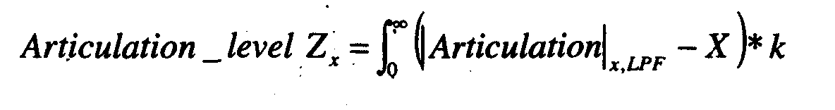
cross link valve - This method has the advantage that each axle can be controlled to suit the conditions in which it is operating. Also it gives the opportunity for the two axles to have different offsets or scaling factors which might be advantageous for example where the loading of the front and rear axles is very different, or where the front and rear suspensions are different.
- The side slope strategy described in relation to the first embodiment can also be applied to this embodiment. However for side slopes where it is desired to have one valve open and the other closed, the system needs to be able to respond to the fact that either one of the valves may be open while the other is closed. For example it could be arranged to ensure simply that, on less extreme side slopes at least one of the valves is closed, on and more extreme side slopes both of them are closed.
- Referring to Figure 2, in a further embodiment of the invention, a vehicle has an independent suspension including
suspension arms front wheels rear wheels vehicle body 122. Asplit anti-roll bar 136 is connected between the tworear wheels halves decoupling device 140 between them, which may for example take the form of that shown in US 4 796 911. This allows the two halves of the anti-roll bar to be locked together so that it acts as a conventional one-piece anti-roll bar resisting articulation of the rear wheels, or decoupled so that it does not significantly resist such articulation. A similar split anti-roll bar could also be connected between thefront wheels electronic control unit 132 controls thedecoupling device 140 based on inputs fromride height sensors vehicle speed sensor 146. The control unit operates in the same way as that of Figure 1, keeping a running measure of the cross articulation of the front and rear wheels, or of the articulation of each axle independently, and then locking the two halves of the anti-roll bar (or bars) together when the articulation integral Z is below a threshold value, and de-coupling the two halves when it is above the threshold. - It will also be appreciated that there are other forms of suspension in which the resistance to single axle articulation or cross articulation can be varied, such as interconnected hydraulic systems, to which this invention is equally applicable.
Claims (21)
- A vehicle suspension system including suspension means (18, 20, 24) for connecting wheels (10, 12, 14, 16) to opposite sides of a vehicle body (22), the suspension means being adjustable so as to adjust the level of resistance it provides to articulation of the wheels, measuring means (42, 43, 44, 45, 32) arranged to measure articulation of the wheels relative to the body, and control means (32), characterized in that the control means is arranged to monitor the level of articulation movement of the wheels (10, 12, 14, 16) and to reduce said resistance if the articulation movement reaches a predetermined level.
- A system according to claim 1 characterized in that the measuring means (42, 43, 44, 45, 32) is arranged to measure the ride height of each of a pair of wheels (10, 12, 14, 16) on opposite sides of the body and to measure the articulation movement of said pair of wheels by comparing their ride heights.
- A system according to claim 1 or claim 2 characterized in that the measuring means (42, 43, 44, 45, 32) is arranged to measure cross articulation movement between two pairs of the wheels (10, 12, 14, 16), each pair being on opposite sides of the body, and the control means is arranged to reduce said resistance if the cross articulation movement reaches a predetermined level.
- A system according to claim 3 characterized in that the measuring means (42, 43, 44, 45) is arranged to measure the ride heights of each of both pairs of wheels (10, 12, 14, 16), and to determine the level of cross articulation movement from the measured ride heights.
- A system according to any foregoing claim characterized in that the control means (32) is arranged to calculate a running measure (Zcross Zx) of the level of articulation movement and to reduce said resistance if the running measure reaches a predetermined level (Zcross,limit).
- A system according to claim 5 characterized in that the running measure (Zcross Zx) is arranged to increase during periods of high articulation movement and to decrease during periods of low articulation movement.
- A system according to 5 or claim 6 characterized in that the running measure (Zcross Zx) includes a speed dependent offset (X) arranged to cause it to reduce when the vehicle is travelling at higher speeds.
- A system according to any one of claims 5 to 7 characterized in that the control means (32) is arranged to increase the level of said resistance when the running measure (Zcross Zx) falls below a predetermined level (Zcross,limit).
- A system according to any one of claims 5 to 8 wherein the control means (32) is arranged to measure the articulation displacement (Across, Af, Ar) of the wheels, and the running measure (Zcross Zx) is a running average of the articulation displacement.
- A system according to any foregoing claim wherein the control means (32) is arranged, when determining the level of said articulation movements, to filter out articulation movements of a frequency higher than a predetermined limit frequency.
- A system according to claim 10 wherein said predetermined limit frequency is of the order of a natural frequency of vibration of the body (22) on the suspension.
- A system according to any foregoing claim wherein the measuring means (42, 43, 44, 45, 32) is arranged to measure the articulation displacement (Across, Af, Ar) of the wheels, and to reduce said resistance only when the articulation displacement is less than a predetermined limit (Across,limit).
- A system according to any foregoing claim wherein the control means (32) is arranged to detect when the vehicle is travelling on a side slope, and, in response, to increase said resistance.
- A vehicle suspension system including suspension means (18, 20, 24) for connecting wheels (10, 12, 14, 16) to opposite sides of a vehicle body (22), the suspension means being adjustable so as to adjust the level of resistance it provides to articulation of the wheels, side slope detection means (42, 43, 44, 45, 32) arranged to detect when the vehicle is on a side slope, and control means (32), characterized in that the control means is arranged, in response to detection of a side slope, to increase said level of resistance.
- A system according to claim 13 or claim 14 wherein said resistance is adjustable between a high level and a low level, and the control means (32) is arranged, in response to detection of a side slope when the resistance is at the low level, to adjust the resistance to the high level.
- A system according to any foregoing claim wherein said resistance is adjustable between a high level and a low level and the control means (32) can be shut down and started up and is arranged: to measure an instantaneous articulation displacement (Af, Ar, Across) of the wheels, on shut down to store the instantaneous articulation displacement of the wheels and the instantaneous level of said resistance, and on start up, if the instantaneous level of said resistance on shut down was the low level, to compare the instantaneous displacement (Af, Ar, Across) with the stored displacement and, if they are substantially the same, to return the resistance to the low level.
- A vehicle suspension system including suspension means (18, 20, 24) for connecting wheels (10, 12, 14, 16) to opposite sides of a vehicle body (22), the suspension means being adjustable so as to adjust the level of resistance it provides to articulation of the wheels, measuring means (42, 43, 44, 45, 32) arranged to measure articulation of the wheels relative to the body, and control means (32) which can be shut down and started up, characterized in that the control means is arranged: to measure an instantaneous displacement (Af, Ar, Across) of the wheels, on shut down to store the instantaneous displacement of the wheels and the instantaneous level of said resistance, and on start up, if the instantaneous level of said resistance on shut down was the low level, to compare the instantaneous displacement with the stored displacement and, if they are substantially the same, to return the resistance to the low level.
- A system according to claim 16 or claim 17 wherein the control means (32) is arranged, if said instantaneous displacement (Af, Ar, Across) and said stored displacement are not substantially the same, to compare an instantaneous articulation displacement of the wheels with a predetermined threshold (Across, limit), and, if it is below the threshold, to return the resistance to the low level.
- A system according to claim 18 wherein the control means (32) is arranged, if said instantaneous articulation displacement is above said predetermined threshold (Across,limit), to delay returning of said resistance to said low level until the instantaneous articulation next falls to said predetermined threshold.
- A system according to any foregoing claim characterized in that the suspension means includes fluid filled suspension units (24) associated with the wheels (10, 12, 14, 16) and the control means (32) is arranged to reduce said resistance by increasing the level of interconnection between units (24) associated with wheels on opposite sides of the vehicle.
- A system according to any foregoing claim characterized in that the suspension means includes a split anti-roll bar (136) and the control means is arranged to decouple at least partially the two halves (136a, 136b) of the anti-roll bar to reduce said resistance.
Applications Claiming Priority (2)
| Application Number | Priority Date | Filing Date | Title |
|---|---|---|---|
| GB9927295 | 1999-11-19 | ||
| GBGB9927295.7A GB9927295D0 (en) | 1999-11-19 | 1999-11-19 | Vehicle suspensions |
Publications (3)
| Publication Number | Publication Date |
|---|---|
| EP1101637A2 true EP1101637A2 (en) | 2001-05-23 |
| EP1101637A3 EP1101637A3 (en) | 2004-12-15 |
| EP1101637B1 EP1101637B1 (en) | 2008-02-27 |
Family
ID=10864755
Family Applications (1)
| Application Number | Title | Priority Date | Filing Date |
|---|---|---|---|
| EP00310158A Expired - Lifetime EP1101637B1 (en) | 1999-11-19 | 2000-11-15 | Vehicle suspensions |
Country Status (4)
| Country | Link |
|---|---|
| US (2) | US6688612B1 (en) |
| EP (1) | EP1101637B1 (en) |
| DE (1) | DE60038153T2 (en) |
| GB (1) | GB9927295D0 (en) |
Cited By (5)
| Publication number | Priority date | Publication date | Assignee | Title |
|---|---|---|---|---|
| EP1362720A3 (en) * | 2002-05-16 | 2005-03-23 | Bayerische Motoren Werke Aktiengesellschaft | Motor vehicle, especially passenger car, with a device for roll-stabilization |
| WO2007095207A1 (en) * | 2006-02-13 | 2007-08-23 | Bfs Diversified Products, Llc | Vehicle suspension system and method |
| WO2008112763A1 (en) * | 2007-03-12 | 2008-09-18 | Bfs Diversified Products, Llc | Vehicle suspension system and method of operating same |
| EP2070742A1 (en) * | 2007-11-29 | 2009-06-17 | ArvinMeritor Technology, LLC | Integrated crossover valve |
| CN100503306C (en) * | 2002-09-24 | 2009-06-24 | 独立行政法人科学技术振兴机构 | Driver of electric automobile |
Families Citing this family (18)
| Publication number | Priority date | Publication date | Assignee | Title |
|---|---|---|---|---|
| GB9927295D0 (en) * | 1999-11-19 | 2000-01-12 | Rover Group | Vehicle suspensions |
| US7178817B1 (en) * | 2002-11-01 | 2007-02-20 | Monaco Coach Corporation | Trailing arm suspension system |
| JP2005271718A (en) * | 2004-03-24 | 2005-10-06 | Aisin Seiki Co Ltd | Vehicle height adjusting device |
| US7380800B2 (en) * | 2005-06-16 | 2008-06-03 | Chrysler Llc | Method and system for controlling a dual mode vehicle suspension system |
| DE102005043555A1 (en) * | 2005-09-12 | 2007-03-15 | GM Global Technology Operations, Inc., Detroit | Control method for electronically controlled damping systems in vehicles and electronically controlled damping system |
| US20080021611A1 (en) * | 2006-07-21 | 2008-01-24 | Hiebert Grant W | Method and apparatus for controlling ride height and leveling of a vehicle having air suspension |
| KR100829031B1 (en) * | 2006-07-25 | 2008-05-16 | 주식회사 만도 | electronic controlled suspension apparatus and vehicle height control method thereof |
| US7871081B1 (en) * | 2008-07-28 | 2011-01-18 | Pin Hsiu Rubber Co., Ltd. | Air-cushion type shock absorbing system that is operated in a wireless controlling manner |
| SE533691C2 (en) * | 2009-04-17 | 2010-12-07 | Scania Cv Ab | Motor vehicles with air suspension systems and computer programs to control an air suspension system. |
| US20110093239A1 (en) * | 2009-10-21 | 2011-04-21 | Holbrook Gregory A | Vehicle weight sensing methods and systems |
| US9452655B2 (en) | 2012-12-18 | 2016-09-27 | Valid Manufacturing Ltd. | Electronic height control for recreational vehicles |
| US8967639B2 (en) * | 2013-01-28 | 2015-03-03 | Saf-Holland, Inc. | Auxiliary axle and suspension assembly |
| DE102013014672A1 (en) | 2013-09-04 | 2015-03-05 | Wabco Gmbh | Method for controlling an electronic brake system |
| DE102014109318A1 (en) * | 2014-07-03 | 2016-01-07 | Dr. Ing. H.C. F. Porsche Aktiengesellschaft | Method for adjusting a rolling moment of an axle of a vehicle for roll stabilization |
| USD746183S1 (en) | 2014-07-09 | 2015-12-29 | Firestone Industrial Products Company, Llc | Gas spring end member |
| DE102017222278B4 (en) | 2017-12-08 | 2021-12-30 | Continental Teves Ag & Co. Ohg | Suspension device for a wheeled vehicle |
| EP3749534A1 (en) * | 2018-02-05 | 2020-12-16 | Base Air Management Limited | Control unit for air management system |
| CN111823801A (en) * | 2020-07-13 | 2020-10-27 | 黄连好 | Semitrailer air suspension |
Citations (1)
| Publication number | Priority date | Publication date | Assignee | Title |
|---|---|---|---|---|
| US5765115A (en) | 1995-08-04 | 1998-06-09 | Ford Motor Company | Pneumatic tilt stabilization suspension system |
Family Cites Families (11)
| Publication number | Priority date | Publication date | Assignee | Title |
|---|---|---|---|---|
| US3857577A (en) * | 1973-09-28 | 1974-12-31 | Honeywell Inc | Proportional frame twist slope control |
| JPS59186713A (en) | 1983-03-18 | 1984-10-23 | Mazda Motor Corp | Suspension for automobile |
| JPS6060024A (en) | 1983-09-09 | 1985-04-06 | Nissan Motor Co Ltd | Roll rigidity controller in vehicle |
| JP3179079B2 (en) * | 1989-06-22 | 2001-06-25 | 富士重工業株式会社 | Active suspension control method for vehicle |
| US5446658A (en) * | 1994-06-22 | 1995-08-29 | General Motors Corporation | Method and apparatus for estimating incline and bank angles of a road surface |
| AUPN384395A0 (en) * | 1995-06-27 | 1995-07-20 | Kinetic Limited | Control method for vehicle suspension system |
| GB9626045D0 (en) * | 1996-12-14 | 1997-01-29 | Rover Group | A vehicle roll stabilising system |
| US5912439A (en) * | 1997-07-28 | 1999-06-15 | Eran; Oded | System and method for safety control in vehicles |
| US6007073A (en) * | 1997-08-14 | 1999-12-28 | Gunter; W. C. | Bush hog tractor balancing device |
| GB9812264D0 (en) * | 1998-06-09 | 1998-08-05 | Rover Group | Vehicle roll control |
| GB9927295D0 (en) * | 1999-11-19 | 2000-01-12 | Rover Group | Vehicle suspensions |
-
1999
- 1999-11-19 GB GBGB9927295.7A patent/GB9927295D0/en not_active Ceased
-
2000
- 2000-11-15 EP EP00310158A patent/EP1101637B1/en not_active Expired - Lifetime
- 2000-11-15 DE DE60038153T patent/DE60038153T2/en not_active Expired - Lifetime
- 2000-11-17 US US09/715,284 patent/US6688612B1/en not_active Expired - Lifetime
-
2003
- 2003-11-06 US US10/702,667 patent/US7040632B2/en not_active Expired - Lifetime
Patent Citations (1)
| Publication number | Priority date | Publication date | Assignee | Title |
|---|---|---|---|---|
| US5765115A (en) | 1995-08-04 | 1998-06-09 | Ford Motor Company | Pneumatic tilt stabilization suspension system |
Cited By (8)
| Publication number | Priority date | Publication date | Assignee | Title |
|---|---|---|---|---|
| EP1362720A3 (en) * | 2002-05-16 | 2005-03-23 | Bayerische Motoren Werke Aktiengesellschaft | Motor vehicle, especially passenger car, with a device for roll-stabilization |
| CN100503306C (en) * | 2002-09-24 | 2009-06-24 | 独立行政法人科学技术振兴机构 | Driver of electric automobile |
| WO2007095207A1 (en) * | 2006-02-13 | 2007-08-23 | Bfs Diversified Products, Llc | Vehicle suspension system and method |
| US7644933B2 (en) | 2006-02-13 | 2010-01-12 | Firestone Industrial Products Company, Llc | Vehicle suspension system and method |
| WO2008112763A1 (en) * | 2007-03-12 | 2008-09-18 | Bfs Diversified Products, Llc | Vehicle suspension system and method of operating same |
| US7957865B2 (en) | 2007-03-12 | 2011-06-07 | Driveright Holdings, Ltd. | Vehicle suspension system and method of operating same |
| EP2070742A1 (en) * | 2007-11-29 | 2009-06-17 | ArvinMeritor Technology, LLC | Integrated crossover valve |
| US9168807B2 (en) | 2007-11-29 | 2015-10-27 | Arvinmeritor Technology, Llc | Integrated crossover valve |
Also Published As
| Publication number | Publication date |
|---|---|
| EP1101637B1 (en) | 2008-02-27 |
| GB9927295D0 (en) | 2000-01-12 |
| US7040632B2 (en) | 2006-05-09 |
| EP1101637A3 (en) | 2004-12-15 |
| US6688612B1 (en) | 2004-02-10 |
| DE60038153T2 (en) | 2009-02-19 |
| US20040150173A1 (en) | 2004-08-05 |
| DE60038153D1 (en) | 2008-04-10 |
Similar Documents
| Publication | Publication Date | Title |
|---|---|---|
| EP1101637B1 (en) | Vehicle suspensions | |
| US5513108A (en) | System for controlling suspension in accordance with road conditions | |
| EP1124701B1 (en) | Vehicle suspensions | |
| US7571039B2 (en) | Vehicle yaw/roll stability control with semi-active suspension | |
| EP0318713B1 (en) | System for control of vehicle suspension | |
| US7552928B2 (en) | Method for operating active stabilizers in motor vehicles and motor vehicle having active stabilizers | |
| US7637513B2 (en) | Vehicle suspension system | |
| US5765115A (en) | Pneumatic tilt stabilization suspension system | |
| US20070017727A1 (en) | Vehicle loading based vehicle dynamic and safety related characteristic adjusting system | |
| EP0285153A2 (en) | Actively controlled automotive suspension system with acceleration and angular velocity dependent anti-pitching and/or anti-rolling feature | |
| US20020109310A1 (en) | Vehicle stability system using active tilting mechanism | |
| EP0324035A1 (en) | Control apparatus for a vehicular suspension system | |
| EP0900152A1 (en) | Motor vehicle suspension system | |
| US6471218B1 (en) | Vehicle suspensions | |
| US5527060A (en) | Load-sensitive vehicular suspension system | |
| US5706196A (en) | Method and apparatus for determining the velocity of a vehicle body | |
| US6789002B1 (en) | Determination of vehicle payload condition | |
| GB2440023A (en) | Vehicle air suspension | |
| EP1105299B1 (en) | Vehicle suspension system | |
| JP2874427B2 (en) | Active suspension system for vehicles | |
| JP3052995B2 (en) | Suspension control device | |
| JP2839912B2 (en) | Vehicle suspension device | |
| JPH0920217A (en) | Action controller for vehicle | |
| JP2906210B2 (en) | Vehicle suspension device | |
| KR0180444B1 (en) | Car body modeling device |
Legal Events
| Date | Code | Title | Description |
|---|---|---|---|
| PUAI | Public reference made under article 153(3) epc to a published international application that has entered the european phase |
Free format text: ORIGINAL CODE: 0009012 |
|
| AK | Designated contracting states |
Kind code of ref document: A2 Designated state(s): AT BE CH CY DE DK ES FI FR GB GR IE IT LI LU MC NL PT SE TR |
|
| AX | Request for extension of the european patent |
Free format text: AL;LT;LV;MK;RO;SI |
|
| PUAL | Search report despatched |
Free format text: ORIGINAL CODE: 0009013 |
|
| AK | Designated contracting states |
Kind code of ref document: A3 Designated state(s): AT BE CH CY DE DK ES FI FR GB GR IE IT LI LU MC NL PT SE TR |
|
| AX | Request for extension of the european patent |
Extension state: AL LT LV MK RO SI |
|
| 17P | Request for examination filed |
Effective date: 20050615 |
|
| AKX | Designation fees paid |
Designated state(s): DE FR GB |
|
| RAP1 | Party data changed (applicant data changed or rights of an application transferred) |
Owner name: LAND ROVER |
|
| GRAP | Despatch of communication of intention to grant a patent |
Free format text: ORIGINAL CODE: EPIDOSNIGR1 |
|
| GRAS | Grant fee paid |
Free format text: ORIGINAL CODE: EPIDOSNIGR3 |
|
| GRAA | (expected) grant |
Free format text: ORIGINAL CODE: 0009210 |
|
| AK | Designated contracting states |
Kind code of ref document: B1 Designated state(s): DE FR GB |
|
| REG | Reference to a national code |
Ref country code: GB Ref legal event code: FG4D |
|
| REF | Corresponds to: |
Ref document number: 60038153 Country of ref document: DE Date of ref document: 20080410 Kind code of ref document: P |
|
| ET | Fr: translation filed | ||
| PLBE | No opposition filed within time limit |
Free format text: ORIGINAL CODE: 0009261 |
|
| STAA | Information on the status of an ep patent application or granted ep patent |
Free format text: STATUS: NO OPPOSITION FILED WITHIN TIME LIMIT |
|
| 26N | No opposition filed |
Effective date: 20081128 |
|
| REG | Reference to a national code |
Ref country code: GB Ref legal event code: 732E Free format text: REGISTERED BETWEEN 20131128 AND 20131204 |
|
| REG | Reference to a national code |
Ref country code: DE Ref legal event code: R082 Ref document number: 60038153 Country of ref document: DE Representative=s name: ANDRAE WESTENDORP PATENTANWAELTE PARTNERSCHAFT, DE |
|
| REG | Reference to a national code |
Ref country code: DE Ref legal event code: R082 Ref document number: 60038153 Country of ref document: DE Representative=s name: ANDRAE WESTENDORP PATENTANWAELTE PARTNERSCHAFT, DE |
|
| REG | Reference to a national code |
Ref country code: DE Ref legal event code: R082 Ref document number: 60038153 Country of ref document: DE Representative=s name: ANDRAE WESTENDORP PATENTANWAELTE PARTNERSCHAFT, DE Effective date: 20150304 Ref country code: DE Ref legal event code: R081 Ref document number: 60038153 Country of ref document: DE Owner name: JAGUAR LAND ROVER LIMITED, COVENTRY, GB Free format text: FORMER OWNER: LAND ROVER, GAYDON, WARWICK, GB Effective date: 20150304 Ref country code: DE Ref legal event code: R082 Ref document number: 60038153 Country of ref document: DE Representative=s name: ANDRAE WESTENDORP PATENTANWAELTE PARTNERSCHAFT, DE Effective date: 20141201 |
|
| REG | Reference to a national code |
Ref country code: FR Ref legal event code: PLFP Year of fee payment: 16 |
|
| REG | Reference to a national code |
Ref country code: FR Ref legal event code: PLFP Year of fee payment: 17 |
|
| REG | Reference to a national code |
Ref country code: FR Ref legal event code: PLFP Year of fee payment: 18 |
|
| REG | Reference to a national code |
Ref country code: FR Ref legal event code: PLFP Year of fee payment: 19 |
|
| PGFP | Annual fee paid to national office [announced via postgrant information from national office to epo] |
Ref country code: DE Payment date: 20181023 Year of fee payment: 19 |
|
| PGFP | Annual fee paid to national office [announced via postgrant information from national office to epo] |
Ref country code: FR Payment date: 20181024 Year of fee payment: 19 Ref country code: GB Payment date: 20181024 Year of fee payment: 19 |
|
| REG | Reference to a national code |
Ref country code: DE Ref legal event code: R082 Ref document number: 60038153 Country of ref document: DE Ref country code: DE Ref legal event code: R082 Ref document number: 60038153 Country of ref document: DE Representative=s name: BARDEHLE PAGENBERG PARTNERSCHAFT MBB PATENTANW, DE |
|
| REG | Reference to a national code |
Ref country code: DE Ref legal event code: R084 Ref document number: 60038153 Country of ref document: DE |
|
| REG | Reference to a national code |
Ref country code: DE Ref legal event code: R119 Ref document number: 60038153 Country of ref document: DE |
|
| GBPC | Gb: european patent ceased through non-payment of renewal fee |
Effective date: 20191115 |
|
| PG25 | Lapsed in a contracting state [announced via postgrant information from national office to epo] |
Ref country code: DE Free format text: LAPSE BECAUSE OF NON-PAYMENT OF DUE FEES Effective date: 20200603 Ref country code: FR Free format text: LAPSE BECAUSE OF NON-PAYMENT OF DUE FEES Effective date: 20191130 Ref country code: GB Free format text: LAPSE BECAUSE OF NON-PAYMENT OF DUE FEES Effective date: 20191115 |