EP1096733A2 - Communication method and communication system - Google Patents
Communication method and communication system Download PDFInfo
- Publication number
- EP1096733A2 EP1096733A2 EP00309222A EP00309222A EP1096733A2 EP 1096733 A2 EP1096733 A2 EP 1096733A2 EP 00309222 A EP00309222 A EP 00309222A EP 00309222 A EP00309222 A EP 00309222A EP 1096733 A2 EP1096733 A2 EP 1096733A2
- Authority
- EP
- European Patent Office
- Prior art keywords
- devices
- polling
- inquiry
- bus
- representative
- Prior art date
- Legal status (The legal status is an assumption and is not a legal conclusion. Google has not performed a legal analysis and makes no representation as to the accuracy of the status listed.)
- Granted
Links
Images


Classifications
-
- H—ELECTRICITY
- H04—ELECTRIC COMMUNICATION TECHNIQUE
- H04L—TRANSMISSION OF DIGITAL INFORMATION, e.g. TELEGRAPHIC COMMUNICATION
- H04L12/00—Data switching networks
- H04L12/28—Data switching networks characterised by path configuration, e.g. LAN [Local Area Networks] or WAN [Wide Area Networks]
- H04L12/40—Bus networks
- H04L12/403—Bus networks with centralised control, e.g. polling
-
- H—ELECTRICITY
- H04—ELECTRIC COMMUNICATION TECHNIQUE
- H04L—TRANSMISSION OF DIGITAL INFORMATION, e.g. TELEGRAPHIC COMMUNICATION
- H04L43/00—Arrangements for monitoring or testing data switching networks
- H04L43/10—Active monitoring, e.g. heartbeat, ping or trace-route
Abstract
Description
- The present invention relates to a communication method and a communication system which perform mutual recognition among plural devices connected to a bus.
- Hitherto, a system has been provided in which plural devices are connected via a bus and operate in a linked manner on the basis of data transmitted through the bus.
- In such a system, it is common practice for each device to perform inquiries and to poll one another in order to recognize other devices. Polling refers to each device confirming (inquiring) with another device whether there is a data transmission request, and if there is a transmission request, the data is received.
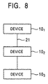
- For example, in a system formed of three devices as shown in Fig. 8, polling in a conventional system is performed mutually among the three devices.
- More specifically, a first device 101 polls a second device 102 and a third device 103 ; the second device 102 polls the first device 101 and the third device 103; and the third device 103 polls the first device 101 and the second device 102.
- However, if each device performs polling of another device in this manner, a substantial amount of the bus bandwidth is occupied for polling. Therefore, if the number of devices is increased, the occupied bus bandwidth will increase considerably.
- Accordingly, it may be conceived that, for example, the first device 101, on behalf of the others, performs polling of other devices, and the result is transmitted as a message to the other devices. According to this scheme, since the devices other than the representative first device 101 do not perform polling, it is possible to reduce the bandwidth occupied.
- However, when the second device 102 and the third device 103 are newly added to the system, the second device 102 and the third device 103 are not recognized until they are polled from the representative first device 101. Therefore, since the second device 102 and the third device 103 are isolated until they are polled from the representative first device 101, it is not possible to make full use of the mutual functions among devices, such as data exchange among devices.
- Also, when the representative first device 101 does not perform polling for some reason or when the representative first device 101 is not present, the second device 102 and the third device 103 cannot be aware of the presence of each other. For this reason, it is not possible to realize functions which are possible only between the second device 102 and the third device 103.
- The present invention has been proposed in view of the above-described circumstances. An object of at least preferred embodiments of the present invention is to provide a communication method and a communication system which are capable of reducing the amount of polling and reducing the bus transmission bandwidth without impairing the mutual functions among devices.
- According to one aspect of the present invention, there is provided a communication method which uses a system in which plural devices are connected with one another by a communication line, one device performs inquiries to other devices, the result of the inquiries is transmitted to the other devices, allowing the devices to recognize one another, characterized in that the other devices perform inquiry more infrequently than the frequency of inquiry of the one device.
- According to another aspect of the present invention, there is provided a communication system in which plural devices are connected with one another by a communication line, one device performs an inquiry to other devices, the result of the inquiries is transmitted to the other devices, allowing the devices to recognize one another, characterized in that the other devices perform an inquiry more infrequently that the frequency of inquiry of the one device.
- An embodiment of the invention will now be described, by way of example only, with reference to the accompanying drawings in which:
- Fig. 1 is a diagram showing the construction of a system in which plural devices are connected to a bus;
- Fig. 2 is a diagram showing the structure of a header and data which follows the header;
- Fig. 3 is a diagram showing a polling command and an acknowledgement;
- Fig. 4 is a diagram showing the structure of a polling command;
- Fig. 5 is a flowchart showing the flow of polling;
- Fig. 6 is a flowchart showing the flow of polling at a different rate of frequency;
- Fig. 7 is a diagram showing polling at a different rate of frequency; and
- Fig. 8 is a diagram showing the construction of a conventional system.
-
- An embodiment of the present invention will now be described below with reference to the accompanying drawings.
- First, referring to Fig. 1, a description is given of a communication system, in which plural devices are connected to a bus of a communication line, and to which a communication method of this embodiment is applied.
- This system consists of n devices: a first device 101 up to an n-th device 10n. Here, n is an integer of 2 or more.
- The first device 101 comprises a first control section 111 for controlling the entirety of this first device 101, and a first interface section 121 for connecting the control section 111 to a bus 21.
- The first control section 111 performs control on each section of the first device 101. Also, the first control section 111 controls communication for other devices connected to the bus 21 via the first interface section 121.
- This first control section 111 can be formed as a microcontroller having, for example, a CPU, a ROM, a RAM, etc.
- The first interface section 121 connects the first control section 111 to the bus 21. The first interface section 121 performs conversion between an internal data format in the first device 101 and a predetermined protocol in the bus 21.
- Since the construction from the second device 102 to the n-th device 10n is the same as the construction of the first device 101, for the sake of simplicity, the same reference numerals are used, and descriptions thereof are omitted.
- The bus 21 connects the devices from the first device 101 to the n-th device 10n so that data is transmitted among the devices. In this bus, communication is performed by a predetermined method in accordance with a predetermined protocol.
- This embodiment has a feature in the method of communicating data transmitted among the devices via the bus 21. That is, in this embodiment, a device which is newly added to the bus due to a new connection or at the activation of power performs an inquiry, that is, polling, only once at that time, and confirms the presence of the device of the other party. After polling is performed once, a polling command from the above-mentioned representative device is received, and the newly connected device does not itself thereafter performs polling.
- Also, in this embodiment, a device which cannot act as a device representing the system performs polling of the representative device more infrequently than the polling frequency of the representative device, and when the device is polled by the representative device, the device does not perform polling of other devices.
- Furthermore, in this embodiment, when the representative device cannot be found by a device, polling is performed of other devices.
- When polling is performed among devices, a client device does not usually perform polling, but performs polling only once at the set-up time of the device.
- A communication method performed in this manner in a system having the construction such as that described above is described below in detail.
- First, a common communication method, which is a basis of this embodiment, in a system in which plural devices are connected to a bus, is described below with reference to Fig. 2.
- Here, a case, in which an n-th device 10n is assumed to be a source device and a first device 101 is assumed to be a destination device, is taken as an example. Needless to say, a combination of a source device and a destination device is not limited to this example.
- The n-th device 10n transmits a header composed of a set of a source device address which is the address of the n-th apparatus 10n and a destination address which is an address of the first device 101 which is the destination. This header is received by the first device 101 via the bus 21.
- For the transmitted header, an acknowledgement is sent back from the first device 101 which is at a destination address. This makes it possible to confirm the fact that the header is received by the first device 101.
- The n-th device 10n transmits data following the header. This data is also received by the first device 101 via the bus 21, and an acknowledgement is sent back from the first device 101.
- A case in which the n-th device 10n performs polling to the first device 101 can also be performed in a manner similar to a case in which data is transmitted.
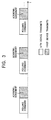
- As shown in Fig. 3, in the case of polling, the n-th device 10n transmits a polling command. As shown in Fig. 4, similarly to the above-mentioned header, the polling command is composed of a set of the source device address which is the address of the n-th apparatus 10n and the destination address which is the address of the first device 101 which is the destination.
- When the first device 101 receives the polling command sent from the n-th device 10n, the first device 101 sends back an acknowledgement. This makes it possible to confirm the fact that the polling command is received by the first device 101.
- As described above, in the case of polling, only the header part is transmitted as a polling command, and the destination device sends back an acknowledgement, making it possible to confirm the presence of the destination device.
- In this embodiment, it is assumed that the basic state is one in which one device among plural devices making up the system performs polling as a representative and the other devices do not perform polling.
- In the following, it is assumed that the first device 101 represents plural devices of the system. Needless to say, the representative device is not limited to the first device 101.
- As a result of polling the other devices, the representative first device 101 obtains information on devices which are present and are connected to the bus 21. This presence information is transmitted from the first device 101 to the other devices. Specifically, the presence information is carried on the data part described with reference to Fig. 2, and is transmitted as a message for the other devices from the representative first device 101.
- In this embodiment, either when a device is newly connected to the bus 21 or when the power is switched on, data is transmitted in accordance with a predetermined communication method. Accordingly, steps of such a communication method are described below with reference to Fig. 5.
- This series of steps is started when, for example, an n-th device 10n is newly connected to the bus 21, or when power to an n-th device 10n which is connected to the bus 21, but is not switched on, is newly switched on.
- In step S11, as shown in Fig. 3, an n-th control section 11n of the n-th device 10n outputs a polling command to the bus 21 via an n-th interface section 12n. The devices, other than the n-th device 10n, which are connected to the bus 21, know that the n-th device 10n is connected to the bus 21 in accordance with this polling command.
- In step S12, the process branches depending on whether or not the n-th device 10n has received an acknowledgement from the first apparatus 101, for example, within a predetermined time. When the first device 101 is present, since the first device 101 sends back an acknowledgement, it is possible to know the presence of the representative first device 101 according to the presence or absence of the acknowledgement.
- More specifically, when it is found that the representative first device 101 is present as a result of receiving the acknowledgement, assuming that the determination is "YES" the process proceeds to step S13.
- Thereafter, the n-th device 10n does not output a polling command, and only sends back an acknowledgement to the polling command from the representative device.
- In this case, the devices other than the first device 101 know that an acknowledgement is returned from the first device 101 to the n-th device 10n and the first device 101 is a representative device.
- On the other hand, when an acknowledgement is not received and it is found that the representative first device 101 is not present, assuming that the determination is "NO", the process returns to step S11. Then, in step S11, a polling command is transmitted again to the representative first device 101.
- In step S13, the process branches depending on whether or not the n-th device 10n has received a polling command from the representative first device 101. Then, when the polling command is received, for example, within a predetermined time, assuming that the determination is "YES", the process proceeds to step S14, and when the polling command is not received, assuming that the determination is "NO", the process returns to step S13.
- The n-th device 10n waits until a polling command from the representative first device 101 occurs in this step S13.
- In step S14, since the n-th device 10n has received the polling command in step S13, an acknowledgement is sent back.
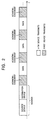
- Next, another communication method of this embodiment is described with reference to Fig. 6. In this communication method, when polling is performed among devices, the devices other than the representative first device 101 perform polling to the representative first device 101 more infrequently. The first device 101 and the n-th device 10n perform polling at different levels of frequency.
- More specifically, as shown in Fig. 7, the representative first device 101 performs polling at an interval of a first period T1, and the n-th device 10n performs polling at an interval of a second period T2. The second period T2 is longer than the first period T1:
- Also, when a polling command is received once, the devices themselves other than the representative first device 101 stop polling.
- In the initial step S21, the process of the n-th device 10n branches depending on whether or not the second period T2 has elapsed from when the polling command was received previously at the time the polling command is newly received.
- The n-th device 10n has contained therein an interval timer for measuring the elapse of time. Whether or not the second period T2 has elapsed is determined according to whether or not this interval timer is 0.
- Then, when the second period T2 has elapsed, assuming that the determination is "YES", the process proceeds to step S22. When the second period T2 has not elapsed, assuming that the determination is "NO", the process proceeds to step S25.
- When the representative first device 101 is present, since the first device 101 issues a polling command at an interval of the first period T1. the second period T2, which is longer than the first period T1, never elapses. Therefore, when the first device 101 is present, the polling command is transmitted only from the representative first device 101.
- Step S22 corresponds to a case in which it is determined that the representative first device 101 is not present in step S21. This is a state in which polling cannot be performed, for example, as a result of the first device 101 being disconnected from the bus 21 or the power being switched off.
- In such a case, the n-th device 10n starts polling at the timing when the interval timer reaches the second period T2.
- In step S23, the process branches depending on whether or not the n-th device 10n has received an acknowledgement, for example, within a predetermined time. When the acknowledgement has been received, a device of the other party which sent back the acknowledgement is present. When the acknowledgement has not been received, a device of the other party which sends back the acknowledgement is not present.
- When the n-th device 10n has received the acknowledgement, assuming that the determination is "YES", the process proceeds to step S24. In step S24, the second period T2 is set to the interval timer. Then, the process returns to step S21.
- When the n-th device 10n has not received the acknowledgement, assuming that the determination is "NO", the process returns to step S22. In step S22, the polling command is transmitted again.
- On the other hand, step S25 corresponds to a case in which it is determined in step S21 that the first device 101 is present. In this case, since the n-th device 10n has received the polling command from the first device 101, the n-th device 10n recognizes the presence of the first device 101 and starts the counting in the interval timer from that time.
- In step S26, the process branches whether or not the n-th device 10n has received a polling command, for example, within a predetermined time. When the polling command has been received, a device of the other party which transmitted the polling command is present. When the polling command has not been received, a device of the other party which transmits the polling command is not present.
- When the n-th device 10n has received the polling command, assuming that the determination is "YES", the process proceeds to step S27.
- In step S27, the second period T2 is set to the interval timer. In step S28, the n-th device 10n transmits an acknowledgement. Then, the process returns to step S21.
- When the n-th device 10n has not received the polling command, assuming that the determination is "NO", the process returns to step S21.
- As has thus been described, in at least preferred embodiments of the present invention, a device which is newly connected to the system performs an inquiry once at the time of connection. Also, a device other than a device representing the system performs an inquiry more infrequently than does the representative device.
- Therefore, according to at least preferred embodiments of the present invention, it is possible to reduce the bandwidth occupied in the bus and to reliably start up mutual functions among devices.
Claims (8)
- A communication method which uses a system in which plural devices are connected with one another by a communication line, one device performs an inquiry to other devices, the result of the inquiries is transmitted to the other devices, allowing the devices to recognize one another,
characterized in that said other devices perform inquiry more infrequently than the frequency of inquiry of said one device. - A communication method according to claim 1, characterized in that a device which is newly connected to a system performs an inquiry only once at the time of connection.
- A communication method according to claim 1, characterized in that said other devices stop an inquiry when an inquiry is received from said one device.
- A communication method according to claim 3, characterized in that said other devices make another inquiry when said one device cannot be found by an inquiry.
- A communication system in which plural devices are connected with one another by a communication line, one device performs an inquiry to other devices, the result of the inquiries is transmitted to the other devices, allowing the devices to recognize one another,
characterized in that the other devices perform an inquiry more infrequently than the frequency of inquiry of said one device. - A communication system according to claim 5, characterized in that a device which is newly connected to a system performs an inquiry only once at the time of connection.
- A communication system according to claim 5, characterized in that said other devices stop an inquiry when an inquiry is received from said one device.
- A communication system according to claim 7, characterized in that said other devices make another inquiry when said one device cannot be found by an inquiry.
Applications Claiming Priority (2)
| Application Number | Priority Date | Filing Date | Title |
|---|---|---|---|
| JP30769399A JP4218152B2 (en) | 1999-10-28 | 1999-10-28 | Communication method and communication system |
| JP30769399 | 1999-10-28 |
Publications (3)
| Publication Number | Publication Date |
|---|---|
| EP1096733A2 true EP1096733A2 (en) | 2001-05-02 |
| EP1096733A3 EP1096733A3 (en) | 2002-09-04 |
| EP1096733B1 EP1096733B1 (en) | 2005-09-21 |
Family
ID=17972097
Family Applications (1)
| Application Number | Title | Priority Date | Filing Date |
|---|---|---|---|
| EP00309222A Expired - Lifetime EP1096733B1 (en) | 1999-10-28 | 2000-10-19 | Communication method and communication system |
Country Status (3)
| Country | Link |
|---|---|
| EP (1) | EP1096733B1 (en) |
| JP (1) | JP4218152B2 (en) |
| DE (1) | DE60022720T2 (en) |
Citations (5)
| Publication number | Priority date | Publication date | Assignee | Title |
|---|---|---|---|---|
| EP0537814A1 (en) * | 1991-09-10 | 1993-04-21 | Koninklijke Philips Electronics N.V. | Multi-station bus system having means for polling and updating of globally relevant information, in particular a station address, and station for use in such system |
| EP0598297A2 (en) * | 1992-11-14 | 1994-05-25 | Siemens Measurements Limited | A polled communications network |
| US5734642A (en) * | 1995-12-22 | 1998-03-31 | Cabletron Systems, Inc. | Method and apparatus for network synchronization |
| WO1998057261A1 (en) * | 1997-06-13 | 1998-12-17 | Intel Corporation | Dynamic discovery of wireless peripherals |
| WO1999031521A1 (en) * | 1997-12-15 | 1999-06-24 | Intelogis | Method and apparatus for power line exchange protocol |
-
1999
- 1999-10-28 JP JP30769399A patent/JP4218152B2/en not_active Expired - Lifetime
-
2000
- 2000-10-19 DE DE60022720T patent/DE60022720T2/en not_active Expired - Lifetime
- 2000-10-19 EP EP00309222A patent/EP1096733B1/en not_active Expired - Lifetime
Patent Citations (5)
| Publication number | Priority date | Publication date | Assignee | Title |
|---|---|---|---|---|
| EP0537814A1 (en) * | 1991-09-10 | 1993-04-21 | Koninklijke Philips Electronics N.V. | Multi-station bus system having means for polling and updating of globally relevant information, in particular a station address, and station for use in such system |
| EP0598297A2 (en) * | 1992-11-14 | 1994-05-25 | Siemens Measurements Limited | A polled communications network |
| US5734642A (en) * | 1995-12-22 | 1998-03-31 | Cabletron Systems, Inc. | Method and apparatus for network synchronization |
| WO1998057261A1 (en) * | 1997-06-13 | 1998-12-17 | Intel Corporation | Dynamic discovery of wireless peripherals |
| WO1999031521A1 (en) * | 1997-12-15 | 1999-06-24 | Intelogis | Method and apparatus for power line exchange protocol |
Non-Patent Citations (1)
| Title |
|---|
| GUTTMAN E: "Service Location Protocol: Automatic Discovery of IP Network Services" IEEE INTERNET COMPUTING, IEEE SERVICE CENTER, PISCATAWAY, NJ, US, vol. 3, no. 4, 1 July 1999 (1999-07-01), pages 71-80, XP002140936 ISSN: 1089-7801 * |
Also Published As
| Publication number | Publication date |
|---|---|
| DE60022720D1 (en) | 2005-10-27 |
| EP1096733A3 (en) | 2002-09-04 |
| DE60022720T2 (en) | 2006-06-29 |
| JP4218152B2 (en) | 2009-02-04 |
| JP2001127775A (en) | 2001-05-11 |
| EP1096733B1 (en) | 2005-09-21 |
Similar Documents
| Publication | Publication Date | Title |
|---|---|---|
| ZA983145B (en) | Data service in a mobile communications network | |
| EP0942560A3 (en) | Apparatus and method for speech transport with adaptive packet size | |
| FI20012179A0 (en) | Communication method and system | |
| WO2007034954A1 (en) | Mobile wireless communication apparatus and method for managing connection status thereof | |
| US20070274254A1 (en) | Connection adapter for communication device | |
| US7421527B2 (en) | Transmission apparatus and transmission method | |
| JPWO2009016785A1 (en) | Communication control system | |
| EP1244252B1 (en) | Gateway and distributed system using the gateway | |
| EP1096733A2 (en) | Communication method and communication system | |
| US20070248107A1 (en) | Connection Adapter for Communication Device | |
| US8446598B2 (en) | Image forming device with a UWB communication function for transmitting search signal corresponding to type of data received, and method for providing data thereof, and system for providing data using the UWB communication function | |
| US20060224769A1 (en) | Method and transmitter for transmitting data packets | |
| KR100226781B1 (en) | Method for recognizing node | |
| JP3037261B2 (en) | Mobile phone communication switching method | |
| KR100667732B1 (en) | Internet protocol apparatus for communicating with private network from outsidenetwork | |
| KR100798190B1 (en) | Selective gateway for multiple protocol working together | |
| EP1708416A2 (en) | Communication system with access point | |
| CN110266778B (en) | Many-to-many long connection network communication device and equipment | |
| JP4207725B2 (en) | Wireless data collection device | |
| KR100358439B1 (en) | Data transmission method using ethernet between compact base controller station | |
| JP2001237985A (en) | Communication system | |
| WO2004036876A1 (en) | Communication device and communication method | |
| JP4828322B2 (en) | base station | |
| JP2002354004A (en) | Connection establishment method between devices using tcp/ip protocol | |
| CA2376718A1 (en) | Interface apparatus provided between two remote control systems having different transmission modes |
Legal Events
| Date | Code | Title | Description |
|---|---|---|---|
| PUAI | Public reference made under article 153(3) epc to a published international application that has entered the european phase |
Free format text: ORIGINAL CODE: 0009012 |
|
| AK | Designated contracting states |
Kind code of ref document: A2 Designated state(s): AT BE CH CY DE DK ES FI FR GB GR IE IT LI LU MC NL PT SE |
|
| AX | Request for extension of the european patent |
Free format text: AL;LT;LV;MK;RO;SI |
|
| PUAL | Search report despatched |
Free format text: ORIGINAL CODE: 0009013 |
|
| AK | Designated contracting states |
Kind code of ref document: A3 Designated state(s): AT BE CH CY DE DK ES FI FR GB GR IE IT LI LU MC NL PT SE |
|
| AX | Request for extension of the european patent |
Free format text: AL;LT;LV;MK;RO;SI |
|
| 17P | Request for examination filed |
Effective date: 20030220 |
|
| 17Q | First examination report despatched |
Effective date: 20030319 |
|
| AKX | Designation fees paid |
Designated state(s): DE FR GB |
|
| GRAP | Despatch of communication of intention to grant a patent |
Free format text: ORIGINAL CODE: EPIDOSNIGR1 |
|
| GRAS | Grant fee paid |
Free format text: ORIGINAL CODE: EPIDOSNIGR3 |
|
| GRAA | (expected) grant |
Free format text: ORIGINAL CODE: 0009210 |
|
| AK | Designated contracting states |
Kind code of ref document: B1 Designated state(s): DE FR GB |
|
| REG | Reference to a national code |
Ref country code: GB Ref legal event code: FG4D |
|
| REF | Corresponds to: |
Ref document number: 60022720 Country of ref document: DE Date of ref document: 20051027 Kind code of ref document: P |
|
| ET | Fr: translation filed | ||
| PLBE | No opposition filed within time limit |
Free format text: ORIGINAL CODE: 0009261 |
|
| STAA | Information on the status of an ep patent application or granted ep patent |
Free format text: STATUS: NO OPPOSITION FILED WITHIN TIME LIMIT |
|
| 26N | No opposition filed |
Effective date: 20060622 |
|
| REG | Reference to a national code |
Ref country code: GB Ref legal event code: 746 Effective date: 20091130 |
|
| REG | Reference to a national code |
Ref country code: FR Ref legal event code: PLFP Year of fee payment: 16 |
|
| REG | Reference to a national code |
Ref country code: FR Ref legal event code: PLFP Year of fee payment: 17 |
|
| REG | Reference to a national code |
Ref country code: FR Ref legal event code: PLFP Year of fee payment: 18 |
|
| REG | Reference to a national code |
Ref country code: FR Ref legal event code: PLFP Year of fee payment: 19 |
|
| PGFP | Annual fee paid to national office [announced via postgrant information from national office to epo] |
Ref country code: DE Payment date: 20191021 Year of fee payment: 20 |
|
| PGFP | Annual fee paid to national office [announced via postgrant information from national office to epo] |
Ref country code: FR Payment date: 20191028 Year of fee payment: 20 |
|
| PGFP | Annual fee paid to national office [announced via postgrant information from national office to epo] |
Ref country code: GB Payment date: 20191021 Year of fee payment: 20 |
|
| REG | Reference to a national code |
Ref country code: DE Ref legal event code: R071 Ref document number: 60022720 Country of ref document: DE |
|
| REG | Reference to a national code |
Ref country code: GB Ref legal event code: PE20 Expiry date: 20201018 |
|
| PG25 | Lapsed in a contracting state [announced via postgrant information from national office to epo] |
Ref country code: GB Free format text: LAPSE BECAUSE OF EXPIRATION OF PROTECTION Effective date: 20201018 |