EP1096339A2 - Process cartridge of an image forming apparatus comprising a tape for maintaining the gears of a photosensitive drum and a developing roller disengaged from each other during transportation of the cartridge - Google Patents
Process cartridge of an image forming apparatus comprising a tape for maintaining the gears of a photosensitive drum and a developing roller disengaged from each other during transportation of the cartridge Download PDFInfo
- Publication number
- EP1096339A2 EP1096339A2 EP00309472A EP00309472A EP1096339A2 EP 1096339 A2 EP1096339 A2 EP 1096339A2 EP 00309472 A EP00309472 A EP 00309472A EP 00309472 A EP00309472 A EP 00309472A EP 1096339 A2 EP1096339 A2 EP 1096339A2
- Authority
- EP
- European Patent Office
- Prior art keywords
- developing roller
- developing
- toner
- process cartridge
- container
- Prior art date
- Legal status (The legal status is an assumption and is not a legal conclusion. Google has not performed a legal analysis and makes no representation as to the accuracy of the status listed.)
- Granted
Links
Images


Classifications
-
- G—PHYSICS
- G03—PHOTOGRAPHY; CINEMATOGRAPHY; ANALOGOUS TECHNIQUES USING WAVES OTHER THAN OPTICAL WAVES; ELECTROGRAPHY; HOLOGRAPHY
- G03G—ELECTROGRAPHY; ELECTROPHOTOGRAPHY; MAGNETOGRAPHY
- G03G21/00—Arrangements not provided for by groups G03G13/00 - G03G19/00, e.g. cleaning, elimination of residual charge
- G03G21/16—Mechanical means for facilitating the maintenance of the apparatus, e.g. modular arrangements
- G03G21/18—Mechanical means for facilitating the maintenance of the apparatus, e.g. modular arrangements using a processing cartridge, whereby the process cartridge comprises at least two image processing means in a single unit
- G03G21/1803—Arrangements or disposition of the complete process cartridge or parts thereof
- G03G21/1817—Arrangements or disposition of the complete process cartridge or parts thereof having a submodular arrangement
- G03G21/1821—Arrangements or disposition of the complete process cartridge or parts thereof having a submodular arrangement means for connecting the different parts of the process cartridge, e.g. attachment, positioning of parts with each other, pressure/distance regulation
-
- G—PHYSICS
- G03—PHOTOGRAPHY; CINEMATOGRAPHY; ANALOGOUS TECHNIQUES USING WAVES OTHER THAN OPTICAL WAVES; ELECTROGRAPHY; HOLOGRAPHY
- G03G—ELECTROGRAPHY; ELECTROPHOTOGRAPHY; MAGNETOGRAPHY
- G03G21/00—Arrangements not provided for by groups G03G13/00 - G03G19/00, e.g. cleaning, elimination of residual charge
- G03G21/16—Mechanical means for facilitating the maintenance of the apparatus, e.g. modular arrangements
- G03G21/18—Mechanical means for facilitating the maintenance of the apparatus, e.g. modular arrangements using a processing cartridge, whereby the process cartridge comprises at least two image processing means in a single unit
- G03G21/1803—Arrangements or disposition of the complete process cartridge or parts thereof
- G03G21/181—Manufacturing or assembling, recycling, reuse, transportation, packaging or storage
-
- G—PHYSICS
- G03—PHOTOGRAPHY; CINEMATOGRAPHY; ANALOGOUS TECHNIQUES USING WAVES OTHER THAN OPTICAL WAVES; ELECTROGRAPHY; HOLOGRAPHY
- G03G—ELECTROGRAPHY; ELECTROPHOTOGRAPHY; MAGNETOGRAPHY
- G03G21/00—Arrangements not provided for by groups G03G13/00 - G03G19/00, e.g. cleaning, elimination of residual charge
- G03G21/16—Mechanical means for facilitating the maintenance of the apparatus, e.g. modular arrangements
- G03G21/18—Mechanical means for facilitating the maintenance of the apparatus, e.g. modular arrangements using a processing cartridge, whereby the process cartridge comprises at least two image processing means in a single unit
- G03G21/1803—Arrangements or disposition of the complete process cartridge or parts thereof
- G03G21/1817—Arrangements or disposition of the complete process cartridge or parts thereof having a submodular arrangement
- G03G21/1825—Pivotable subunit connection
-
- G—PHYSICS
- G03—PHOTOGRAPHY; CINEMATOGRAPHY; ANALOGOUS TECHNIQUES USING WAVES OTHER THAN OPTICAL WAVES; ELECTROGRAPHY; HOLOGRAPHY
- G03G—ELECTROGRAPHY; ELECTROPHOTOGRAPHY; MAGNETOGRAPHY
- G03G21/00—Arrangements not provided for by groups G03G13/00 - G03G19/00, e.g. cleaning, elimination of residual charge
- G03G21/16—Mechanical means for facilitating the maintenance of the apparatus, e.g. modular arrangements
- G03G21/18—Mechanical means for facilitating the maintenance of the apparatus, e.g. modular arrangements using a processing cartridge, whereby the process cartridge comprises at least two image processing means in a single unit
- G03G21/1839—Means for handling the process cartridge in the apparatus body
- G03G21/1857—Means for handling the process cartridge in the apparatus body for transmitting mechanical drive power to the process cartridge, drive mechanisms, gears, couplings, braking mechanisms
- G03G21/186—Axial couplings
-
- G—PHYSICS
- G03—PHOTOGRAPHY; CINEMATOGRAPHY; ANALOGOUS TECHNIQUES USING WAVES OTHER THAN OPTICAL WAVES; ELECTROGRAPHY; HOLOGRAPHY
- G03G—ELECTROGRAPHY; ELECTROPHOTOGRAPHY; MAGNETOGRAPHY
- G03G21/00—Arrangements not provided for by groups G03G13/00 - G03G19/00, e.g. cleaning, elimination of residual charge
- G03G21/16—Mechanical means for facilitating the maintenance of the apparatus, e.g. modular arrangements
- G03G21/1642—Mechanical means for facilitating the maintenance of the apparatus, e.g. modular arrangements for connecting the different parts of the apparatus
- G03G21/1647—Mechanical connection means
-
- G—PHYSICS
- G03—PHOTOGRAPHY; CINEMATOGRAPHY; ANALOGOUS TECHNIQUES USING WAVES OTHER THAN OPTICAL WAVES; ELECTROGRAPHY; HOLOGRAPHY
- G03G—ELECTROGRAPHY; ELECTROPHOTOGRAPHY; MAGNETOGRAPHY
- G03G2221/00—Processes not provided for by group G03G2215/00, e.g. cleaning or residual charge elimination
- G03G2221/16—Mechanical means for facilitating the maintenance of the apparatus, e.g. modular arrangements and complete machine concepts
- G03G2221/18—Cartridge systems
- G03G2221/1807—Transport of supply parts, e.g. process cartridges
Definitions
- the present invention relates to a process cartridge.
- the process cartridge is a cartridge containing at least a developing roller as developing means and an electrophotographic photosensitive member as a unit, the cartridge being detachably mountable to a main assembly of an electrophotographic image forming apparatus.
- the electrophotographic image forming apparatus is an apparatus in which an image is formed on a recording material (recording paper, textile or the like) using an electrophotographic image forming process, and includes an electrophotographic copying machine, an electrophotographic printer (a LED printer, laser beam printer and so on, an electrophotographic printer type facsimile machine, an electrophotographic word processor and the like.
- a process cartridge which integrally contains an electrophotographic photosensitive member and process means actable on the electrophotographic photosensitive member, the process cartridge being detachably mountable to the main assembly of the electrophotographic image forming apparatus.
- the process cartridge type With this process cartridge type, the maintenance of the apparatus can be carried out in effect without service people. Therefore, the process cartridge type is widely used in the field of the electrophotographic image forming apparatus.
- Such a process cartridge forms an image on recording material with toner.
- the developing roller of the developing means and the electrophotographic photosensitive member are coupled with other by gears.
- the photosensitive drum is press-contacted to the spacer rollers at the end of portions of the developing roller.
- the gear fixed coaxially to the photosensitive drum and the gear coaxially fixed to the developing roller are in a regular meshing engagement with each other.
- the gear teeth of the gears are abutted with a result of rotation of the photosensitive drum and the developing roller. If the directions of the rotations are all opposite from the directions during the image forming operation, the blow -out preventing sheet counterdirectionally contacted to the peripheral surface of the developing roller may be turned over.
- the present invention provides a process cartridge in which the toner leakage to the outside is effectively prevented.
- a process cartridge detachably mountable to a main assembly of an electrophotographic image forming apparatus comprising: an electrophotographic photosensitive drum; a drum gear provided at one longitudinal end of the photosensitive drum; a developing roller for developing with toner an electrostatic latent image formed on the photosensitive drum; a developing roller gear, provided at one longitudinal end of developing roller, for meshing engagement with the drum gear to transmit a driving force for rotating developing roller from the drum gear; a cleaner container supporting the photosensitive drum; a toner developing container supporting developing roller; a coupling member for rotatably connection the cleaner container and the toner developing container with each other; an urging member for urging the cleaner container and the toner developing container coupled by the coupling member in the direction of engagement of the drum gear and the developing roller gear with each other; a tape stuck continuously on the cleaner container and the toner developing container to maintain, against an urging force provided by the urging member, a state in which the drum gear developing roller gear are disengaged from each other
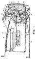
- Figure 1 is a longitudinal sectional view of an electrophotographic image forming apparatus.
- Figure 2 is a longitudinal sectional view of an electrophotographic image forming apparatus.
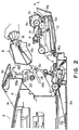
- Figure 3 is a perspective view of an electrophotographic image forming apparatus.
- Figure 4 is a longitudinal sectional view of a process cartridge.
- Figure 5 is a perspective view of a process cartridge.
- Figure 6 is a side view of a process cartridge.
- Figure 7 is a partly broken side view of a process cartridge.
- Figure 8 is a top plan view of a frame of a toner developing container.
- Figure 9 is a side view of a drum shutter.
- Figure 10 is a top plan view of a process cartridge.
- Figure 11 is an exploded perspective view of a toner developing container and a cleaner container.
- Figure 12 is a developed schematic view of a cleaner container.
- Figure 13 is a horizontal sectional view of a toner developing container.
- Figure 14 is a perspective view of a toner developing container without a developing roller.
- Figure 15 is an exploded perspective view of supporting means for the developing roller.
- Figure 16 is an exploded perspective view of a toner developing container.
- Figure 17 is a top plan view of a toner developing container from which the developing roller and the developing blade have been removed.
- Figure 18 is an enlarged review of E part in Figures 17.
- Figure 19 is an enlarged view of F part of Figures 17
- Figure 20 is a front view of a toner developing container as seen in the direction opposite from the mounting direction of the process cartridge.
- Figure 21 is a longitudinal sectional view of a process cartridge.
- Figure 22 is a side view of a process cartridge.
- Figure 23 is a side view of a process cartridge.
- Figure 24 is a side view of a toner developing container.
- Figure 25 is a side view of a toner developing container.
- Figure 26 is a longitudinal sectional view of a connecting portion between the toner developing container and the cleaner container.
- Figure 27 is a perspective view of a toner developing container and a cleaner container.
- Figure 28 is a perspective view of the photosensitive drum and the developing roller during image forming operation.
- Figure 29 is a longitudinal sectional view of the process cartridge during the transportation thereof.
- Figure 30 is a perspective view illustrating a relationship between the photosensitive drum and the charging roller during transportation of the process cartridge.
- Figure 31 is a perspective view of a process cartridge during transportation thereof.
- Figure 32 is a longitudinal sectional view of a toner filling according to a further embodiment of the present invention.
- Figure 33 is a longitudinal sectional view of an electrophotographic image forming apparatus.
- Figure 34 is a perspective view of an electrophotographic image forming apparatus.
- Figure 35 is a longitudinal sectional view of a process cartridge.
- Figure 36 is a perspective view of a process cartridge.
- Figure 37 is a side view of a process cartridge.
- Figure 38 is a partly broken side view of a process cartridge.
- Figure 39 is a plan view of a frame constituting a toner developing container.
- Figure 40 is a side view of a drum shutter.
- Figure 41 is a plumb view of a process cartridge.
- Figure 42 is an exploded perspective view of a toner developing container and a cleaner container.
- Figure 43 is a schematic developed view of a cleaner container.
- Figure 44 is a horizontal sectional view of a toner developing container.
- Figure 45 is a perspective view of a toner developing container without a developing roller.
- Figure 46 is an exploded perspective view of a supporting means for supporting a developing roller.
- Figure 47 is an exploded perspective view of a toner developing container.
- Figure 48 is a top plan view of a toner developing container without the developing roller and the developing blade.
- Figure 49 is an enlarged view of E part shown in Figure 48.
- Figure 50 is an enlarged view of F part shown in Figure 48
- Figure 51 is a front view of a toner developing container as seen in the direction opposite from the process cartridge mounting direction.
- Figure 52 is a longitudinal sectional view of a process cartridge.
- Figure 53 is a side view of a process cartridge.
- Figure 54 is a side view of a process cartridge.
- Figure 55 is a side view of a toner developing container.
- Figure 56 is a side view of a toner developing container.
- Figure 57 is a longitudinal sectional view illustrating a connecting portion between the toner developing container and the cleaner container.
- Figure 58 is a perspective view of a cleaner container and a toner developing container.
- Figure 59 is a longitudinal sectional view of a process cartridge during transportation.
- Figure 60 is a perspective view of a process cartridge during transportation.
- the remanufacturing of the process cartridge from which the toner has been used up is disassembled into the toner developing container and the cleaner container, and the toner developing container is partly disassembled, and they are reassembled to provide a process cartridge having the toner developing container which is similar in function to the new process cartridge but has a partly different structure from the new process cartridge.
- the image forming apparatus in this embodiment is an electrophotographic image forming apparatus (laser beam printer) A, as shown in Figure 1, wherein an electrophotographic photosensitive member in the form of a drum is exposed to information light modulated in accordance with image information from an optical system 1, so that latent image is formed on the photosensitive member, and the latent image is developed into a toner image.
- the recording material 2 is fed out one by one from a sheet feeding cassette 3a using a pick-up roller 3b and separation claws 3c press-contacted at the corners of the top surface of the recording material 2, and the sheet is fed by feeding means 3 including a feeding path 3d and a pair of registration rollers.
- the toner image formed on the electrophotographic photosensitive member in the process cartridge B is transferred onto the recording material 2 by applying a voltage to transfer means in the form of a transfer roller 4, and then the recording material 2 is fed to fixing means 5 on a feeding path 3f.
- the fixing means 5 comprises a driving roller 5a and a fixing roller 5c containing a heater 5b therein, and a pressure and heat is imparted to the recording material 2 which is passing therethrough, by which the transferred toner image is fixed on the recording material.
- the recording material 2 is further fed by discharging rollers, and is discharged to a discharging portion 6 through a reverse feeding path.
- the process cartridge B contains the electrophotographic photosensitive member and at least one of process means.
- the process means includes charging means for electrically charging the electrophotographic photosensitive member, the developing means for developing a latent image formed on the electrophotographic photosensitive member, cleaning means for cleaning the surface of the electrophotographic photosensitive member to remove residual toner.
- the electrophotographic photosensitive member in the form of an electrophotographic photosensitive drum 7 having a photosensitive layer is rotated, and a voltage is applied on the charging roller 8 which is the charging means, so that surface of the photosensitive drum 7 is uniformly charged, and the photosensitive drum 7 is exposed to light image from the optical system 1 through an opening 9, by which and electrostatic latent image is formed, and the image is developed by developing means 10.
- the toner in a toner accommodating portion 10a is fed out by feeding means in the form of a rotatable toner feeding member lOb, and a developing roller 10d containing therein a stationary magnet is rotated, by which a lady of toner particles triboelectrically charged by the developing blade 10e is formed on the surface of the developing roller 10d.
- the toner is selectively transferred onto the photosensitive drum 7 so that toner image is formed.
- the developing roller 10d functions to supply the toner to the photosensitive drum 7.
- the developing blade 10e functions to regulate a thickness of the toner layer on the surface of the developing roller 10d.
- the transfer roller 4 is supplied with a voltage having a polarity opposite from the polarity of the toner image, by which the toner image is transferred onto the recording material 2. Thereafter, the residual toner remaining on the photosensitive drum 7 is scraped off by the cleaning blade 11a, and the removed toner is received by a receptor sheet 11b, and the received toner is collected into a removed toner accommodating portion 11c.
- Various parts such as photosensitive drum 7 is supported and accommodated in a cartridge frame which is provided by coupling the toner developing container 12 and the cleaner container 13.
- the cartridge is mounted to the main assembly 14 of the apparatus.
- guide portions correspondingly to the guide grooves 16 to be guided by the guide groove 16.
- the guide portions are projected substantially symmetrically at the opposite longitudinal ends, respectively.
- it comprises a boss 18 and a rib 19 which are integral.
- the boss 18 and the rib 19 are integrally formed with the cleaner container 13 to which the photosensitive drum 7 is mounted, and the boss 18 is disposed on an extension of a rotational excess of the photosensitive drum 7, and the rib 19 is extended from the boss 18 in an inserting direction of the process cartridge B as indicated by an arrow C in Figure 5.
- the rib 19 extends inclined downwardly in conformity with the guide groove 16.
- the gravity center of the process cartridge B is at rib 19 side of the boss 18.
- the drum gear 51a ( Figure 5) fixed to an end of the photosensitive drum 7 is brought into meshing engagement with a driving gear 22 ( Figure 2) provided in the main assembly 14, so that driving force can be transmitted to the process cartridge B.
- the cover member 15 is closed, by which the shutter opening lever 55 which is interrelated with the cover member is is rotated in the clockwise direction about the shaft 55c from a position 55a to a position 55b, so that it is engaged with a pin 28a provided on the drum shutter member 28 as shown in Figure 10, and the drum shutter member 28 is opened about a pin 29 mounted to the cleaner container 13 against a spring force of a spring 27, thus opening a transfer opening 13n.
- the coil spring 27 is fitted around the pin 29, and one end thereof is engaged to the cleaner container 13, and the other end is engaged to the drum shutter member 28, and therefore, when the cover member 15 is open or when the process cartridge B is outside the main assembly 14, the drum shutter member 28 closes the transfer opening 13n by the spring force of the coil spring 27.
- the cartridge frame is made of polystyrol resin material by injection molding, and as shown in Figure 4, a lower developing frame 12b is welded to a side of the developing device frame 12a, and a cap member 12c is welded to the upper portion, thus constituting a toner developing container 12.
- a cap member 13b is welded to a top of a cleaning frame 13a to constitute an integral cleaner container 13. Then, the cleaner container 13 is coupled with the toner developing container 12 to constitute a cartridge frame.
- the developing device frame 12a is provided at an end thereof with a toner supply opening 12a1, as shown in Figure 13, 14, is also provided at one longitudinal end with a toner filling opening 12a2.
- the developing device frame 12a is provided therein with a plurality of erected supporting members (not shown) in the longitudinal direction.
- the toner supply opening 12a1 permits supply of the toner from the toner accommodating portion 10a to the developing roller 10d.
- the toner in the toner accommodating portion 10d is supplied to the developing roller 10d through the toner supply opening 12a1.
- a toner feeding member 10b is mounted in the developing device frame 12a, and thereafter, the cap member 12c is welded to the developing device frame 12a.
- a toner seal 31 in the form of a film is welded on a surface 12a5 of the seat formed around the circumference of the toner supply opening 12a1 of the toner developing container 12 to seal the opening 12a1.
- the toner is filled through the toner filling opening 12a2, and thereafter, the filling opening 12a2 is plugged by a cap 32 to seal the toner accommodating portion 10a.
- the toner seal 31 sealing the toner supply opening 12a1, as shown in Figure 13, is folded back at one longitudinal end of the opening 12a1, and the free end thereof is extended out through a slit 12a8 of the developing device frame 12a.
- the free end of the toner seal 31 is nipped by fingers of the user and is pulled out when the user starts use of the process cartridge B.
- an elastic sealing material 10h such a felt is provided in the slit 12a8 at an end, closer to the fee end, of the toner seal 31.
- the elastic sealing material 10h is overlaid on the toner seal 31 and urges the toner seal 31. Therefore, when the toner seal 31 is pulled out, the elastic sealing material 10h occupies the slit 12a8 which has been occupied by the toner seal 31 to be press-contacted to a wall of the developing device frame 12a, thus preventing leakage of the toner to the outside.
- the lower developing frame 12b is welded to the developing device frame 12a.
- the developing device frame 12a is provided at the opposite longitudinal ends of the toner supply opening 12a1 with arcuate portions 12a6 at which the end seals 34 are to be mounted.
- a flat flange 12a16 is extended between the arcuate portions 12a6 below the seal sticking seat surface 12a5, and the flange 12a16 is substantially perpendicular to the seal sticking seat surface 12a5.On dead hand, lower developing frame 12b is engaged with you in the longitudinally opposing surfaces of the arcuate portions 12a6.
- the lower developing frame 12b has a length which is smaller than the distance between the opposing surfaces of the arcuate portion 12a6 by 2 x g where g is a gap at each ends.
- the flange 12a16 is provided with holes 12a17
- the lower developing frame 12b is provided with dowels 12b3 for engagement with the holes 12a17, respectively.
- the dowels 12b3 being in engagement with the respective hole 12a17, the bottom surface of the lower developing frame 12b and the top surface of the flange 12a16 of the developing device frame 12a are welded to each other.
- gap g is formed between the arcuate portion 12a6 and the lower developing frame 12b at each end.
- the dimension of the gap g is not constant when the lower developing frame 12b is fixed to the developing device frame 12a.
- Each of the opposite ends of the lower developing frame 12b is provided with an outward projection 12b2 ( Figure 8).
- the developing device frame 12a is provided at each of the end portions with a recess 12a18 for engagement with a projection 12b2 when the dowels 12b3 are engaged with the holes 12a17 for the purpose of welding or bombing of the lower developing frame 12b.
- a gap g1 is provided between the recess 12a18 and the projection 12b2.
- the gap is substantially equal to the gap g formed between the lower developing frame 12b and the arcuate portion 12a6.
- the arcuate portion 12a6 of the developing device frame 12a is provided with a sticking portion 12a20 to which the end seal 34 is stuck.
- the sticking portion 12a20 has an arcuate peripheral surface having a common axis with the arcuate portion 12a21 provided longitudinally outside of the arcuate portion 12a6.
- the axis is the rotational axis of the developing roller 10d in the toner developing container 12.
- the sticking portion 12a20 is provided with an arcuate surface having a radius which is smaller than that of the outer arcuate portion 12a21.
- An end of the sticking portion 12a20 ends short of (inside) the circumference of the outer arcuate portion 12a21.
- a slit 12d is provided between the arcuate portion 12a6 and the lower developing frame 12b.
- the slit 12d is on an optical path of a laser beam passing through a gap (development gap) formed between the photosensitive drum 7 and the developing roller 10d provided by the spacer roller 10d1 which is disposed to each of the opposite and portions of the photosensitive drum 7 and the developing roller 10d.
- Optical path passes through the slit 12d, a slit 10e6 provided in the metal blade 10e2 and a hole 13b1 formed in the cap member 13b.
- the laser beam emitted from the laser source 86 has a width which is larger than the gap (approx. 300 ⁇ m) between the photosensitive drum 7 and the developing roller 10d.
- the laser beam emitted from the laser source 86 travels through the hole 13b1, the slit 10e6, the gap between the photosensitive drum 7 and the developing roller 10d and the slit 12d, and is then received by a photoreceptor 87.
- the width of the laser beam received by the photoreceptor 87 measured in a direction parallel with the face of the sheet of the drawing of Figure 21. Therefore, the development gap can be detected.
- the measurement of the gap between the photosensitive drum 7 and the developing roller 10d using the laser beam is effected at each of opposite longitudinal ends of the photosensitive drum 7 (two positions). Therefore, the hole 13b1, the slit and the slit 10e6, 12d are each provided at at least two positions (adjacent opposite longitudinal ends).
- the end seal 34 functions to provide a seal between the developing device frame 12a and each of the end portions of the developing blade 10e and each of the end portions of the developing roller 10d, and it comprises an arcuate portion 34a contactable to the developing roller 10d along its circumferential surface and an integral linear portion 34b along a rear surface of each of the end portions of the metal blade 10e2.
- the outer circumference of the arcuate portion 34a is stuck to the sticking portion 12a20 of the developing device frame 12a.
- a seal 35 of urethane foam or the like is mounted and extended between blade mounting seat surfaces 12a4 formed above the toner discharging opening 12a1 of the toner discharging, and the developing blade 10e is screwed on the blade mounting seat surface 12a4 with the seal 35 therebetween.
- the seal 35 is compressed between the metal blade 10e2 and a developing device frame 12a so that sealing is accomplished between the metal blade 10e2 and the developing device frame 12a.
- the development holder 36 shown in Figures 16, 24 is secured to one of the ends of the developing device frame 12a, and the development holder 37 shown in Figures 16, 25 is secured to the other end thereof.
- the development holders 36, 37 are fixed to the developing device frame 12a by small screws 56, 57.
- the shaft 10d2 of the developing roller 10d at one end is engaged with a fixed bearing 33b which is in the form of a shaft integral with the development holder 37 shown in Figures 15, 16.
- the developing roller shaft 10d2 is received by a bearing hole 33a2 of the bearing 33a at the other end of the developing roller 10d, and as shown in Figure 15, a hole 33a4 is engaged with a positioning dowel 12a7 provided on the developing device frame 12a at an outside of one of the longitudinal ends.
- the developing roller gear 10f is engaged with the developing roller shaft 10d2.
- the engaging portion 33a3 of the bearing 33a is engaged with a part-cylindrical engaging portion 36a of the development holder 36. At this time, the developing roller gear 10f is accommodated in the development holder 36.
- a small screw 56 is penetrated through a hole 36c of the development holder 36, a hole 33a1 of the bearing 33a and is threaded into a female screw 12a13 of the developing device frame 12a.
- the gear accommodating portion 36b outside the development holder 36 is part-cylindrical, and when the toner developing container 12 and a cleaner container 13 are coupled, the developing roller gear 10f is brought into meshing engagement with the drum gear 51a through the open part of the gear accommodating portion 36b.
- Each of the development holders 36, 37 is provided with an integral arm portion 38 functioning as a connecting portion for connection did in the toner developing container 12 and the cleaner container 13.
- the toner developing container 12 having the various members constituting the developing means and the cleaner container 13 having the various members constituting the photosensitive drum 7, the charging roller 8 and a cleaning means are coupled by the arm portions 38 to constitute the process cartridge B.
- Figures 7 and 11 are a side view and a perspective view illustrating the coupling between the containers 12, 13; Figure 26 shows inside of the coupling portion; and Figures 24, 25 are side views of the copper end portion of the toner developing container 12.
- the containers 12, 13 are rotatably coupled through the arms 38 at the opposite ends. Since the covering structures at the left and right ends are substantially the same, therefore, the description will be made as to only one end. However, the portions which a different between the left and right hands will be described for the respective ends.
- the developing device frame 12a is provided with an integral spring mounting portion 12a28, on which a compression coil spring 40 is mounted.
- the position of the compression coil spring 40 is adjacent one of the longitudinal ends of the developing device frame 12a, and is away from the arm portion 38 in the direction perpendicular to the longitudinal direction.
- the compression coil spring 40 is extended out in parallel with the arm portion 38.
- a through-hole 38b is provided for receiving a pin 41 which will be described hereinafter.
- an outer wall 13q of the cleaner container 13 is provided with a hole 13c for receiving the pin 41, and an inner wall 13d thereof is provided with a hole 13e for being press-fitted by the pin 41.
- the hole 13c and the hole 13e are aligned along a line parallel with the photosensitive drum 7.
- An elongated bore 38b1 is formed in the arm portion 38 and the other end of the cleaner container 13, and a line connecting the center of the elongated bore 38b1 and the hole 38b passes through the centers of the holes 13c, 13e.
- the elongated bore 38b1 is elongated in a direction parallel with a line connecting the center of the photosensitive drum 7 and the center of the developing roller 10d, and a width of the elongated bore 38b1 is equal to the diameter of the pin 41.
- the arm portion 38 of the toner developing container 12 is inserted into the recess 13h of the cleaner container 13, and the pin 41 is penetrated through the hole 13c, 13c of the cleaner container 13, the through hole 38b, of the arm portion 38 and the elongated bore 38b1 in the order named, and is press-fitted into the hole 13e, 13e of the inner wall 13d.
- the toner developing container 12 and the cleaner container 13 are rotatably coupled for rotation about the pin 41.
- the compression coil spring 40 mounted to the developing device frame 12a is compressed out the abutment to the spring seat 13f ( Figure 26) of the cleaner container 13.
- the photosensitive drum 7 and the developing roller 10d are urged toward each other about the pin 41 so that spacer rollers 10d1 of the developing roller 10d are press-contacted to the photosensitive drum 7.
- the photosensitive drum 7 and spacer rollers 10d1 of the developing roller 10d are contacted to each other at the generating lines thereof.
- the generating lines are parallel with the center lines of the photosensitive drum 7 and the developing roller 10d.
- Figure 7 shows an end surface portion which is opposite from the end where the compression coil spring 40 is provided. Opposite ends of a tension coil spring 59 are engaged with a spring hook 13p of the cleaner container 13 and a spring hook 12a29 of the developing device frame 12a of the toner developing container 12, respectively.
- the direction of the tension coil spring 59 is substantially parallel with a line connecting the centers of the photosensitive drum 7 and the developing roller 10d.
- the developing roller 10d mounted in the toner developing container 12 is urged toward the photosensitive drum 7 mounted in the cleaner container 13, so that spacer rollers 10d1 at the opposite longitudinal ends of the developing roller 10d are contacted to the photosensitive drum 7 by which the developing roller 10d is correctly position relative to the photosensitive drum 7.
- the drum gear 51a fix to the end of the photosensitive drum 7 is brought into meshing engagement with the developing roller gear 10f fixed to the and of the developing roller 10d, so that driving force can be transmitted.
- the photosensitive drum 7 rotates in the direction indicated by an arrow B, that is, if the photosensitive drum 7 and the developing roller 10d are rotated in the direction opposite from the normal direction, the toner may be leaked out through between the blow-out preventing sheet and the developing roller 10d, and in the worst-case, the seal may be wound around the developing roller since the preventing sheet is contacted to the developing roller counter-directionally.
- the back clearance of the meshing between the drum gear 51a and the developing roller gear 10f is made larger than that during the image formation to avoid abutment between the tooth surfaces during the transportation. Another alternative is to disengage them for the transportation.
- Figure 31 is a perspective view with the tape stuck in this manner.
- a force is applied to the toner developing container 12 and the cleaner container 13 toward each other and positions across a vertical surface passing through a point P which is a pivot between the toner developing container 12 and the cleaner container 13 from the portion where the photosensitive drum 7 and the developing roller 10d are provided, as indicated by an arrow N in Figure 29, by which the back clearance between the drum gear 51a and the developing roller gear 10f is increased, or they are disengaged from each other.
- the force is against the spring force provided by the tension coil spring 59 ( Figure 7) and the compression coil spring 40 ( Figure 11) for urging the photosensitive drum 7 and the developing roller 10d toward each other. Therefore, the tape 81 is stretched by the springs 40, 59. Therefore, the tape 81 has sufficient width and thickness such that stress during the transportation is within a tolerable range, and in addition, the adhesive material or the adhesive material for the tape has also sufficient bonding strength against the toner developing device frame 12a and the cleaner container 13.
- the tape 81 may be an adhesive tape which is easy to handle.
- the tape 81 is a single tape, and is disposed in the longitudinally central portion of the process cartridge B. By doing so, the containers 12, 13 are not deformed irregularly despite the regular force imparted to the toner developing container 12 and/or the cleaner container 13.
- An end of the tape 81 is folded back to provide a tag 81a.
- the tape 81 can be peeled off using the tag 81a.
- the tape 81 is peeled off using the tag 81a. Or, the tape 81 is cut by scissors at a portion between the toner developing container 12 and the cleaner container 13 where the tape 81 is not stuck. Then, the toner developing container 12 and the cleaner container 13 are rotated to each other about the pin 41 by the spring forces provided by the springs 40, 59, so that developing roller gear 10f and the drum gear 51a are brought into meshing engagement with each other. Simultaneously, the spacer roller 10d1 and the photosensitive drum 7 are press-contacted to each other.
- the exposure opening 9 for transmitting the image light onto the photosensitive drum 7 is closed. Therefore, the photosensitive drum 7 is substantially completely closed with the aid of the drum shutter member 28.
- the image forming apparatus in this embodiment is an electrophotographic image forming apparatus (laser beam printer) A, as shown in Figure 32, wherein an electrophotographic photosensitive member in the form of a drum is exposed to information light modulated in accordance with image information from an optical system 1, so that latent image is formed on the photosensitive member, and the latent image is developed into a toner image.
- the recording material 2 is fed out one by one from a sheet feeding cassette 3a using a pick-up roller 3b and separation claws 3c press-contacted at the corners of the top surface of the recording material 2, and the sheet is fed by feeding means 3 including a feeding path 3d and a pair of registration rollers.
- the toner image formed on the electrophotographic photosensitive member in the process cartridge B is transferred onto the recording material 2 by applying a voltage to transfer means in the form of a transfer roller 4, and then the recording material 2 is fed to fixing means 5 on a feeding path 3f.
- the fixing means 5 comprises a driving roller 5a and a fixing roller 5c containing a heater 5b therein, and a pressure and heat is imparted to the recording material 2 which is passing therethrough, by which the transferred toner image is fixed on the recording material.
- the recording material 2 is further fed by discharging rollers, and is discharged to a discharging portion 6 through a reverse feeding path.
- the process cartridge B contains the electrophotographic photosensitive member and at least one of process means.
- the process means includes charging means for electrically charging the electrophotographic photosensitive member, the developing means for developing a latent image formed on the electrophotographic photosensitive member, cleaning means for cleaning the surface of the electrophotographic photosensitive member to remove residual toner.
- the electrophotographic photosensitive member in the form of an electrophotographic photosensitive drum 7 having a photosensitive layer is rotated, and a voltage is applied on the charging roller 8 which is the charging means, so that surface of the photosensitive drum 7 is uniformly charged, and the photosensitive drum 7 is exposed to light image from the optical system 1 through an opening 9, by which and electrostatic latent image is formed, and the image is developed by developing means 10.
- the toner in a toner accommodating portion 10a is fed out by feeding means in the form of a rotatable toner feeding member 10b, and a developing roller 10d containing therein a stationary magnet is rotated, by which a lady of toner particles triboelectrically charged by the developing blade 10e is formed on the surface of the developing roller 10d.
- the toner is selectively transferred onto the photosensitive drum 7 so that toner image is formed.
- the developing roller 10d functions to supply the toner to the photosensitive drum 7.
- the developing blade 10e functions to regulate a thickness of the toner layer on the surface of the developing roller 10d.
- the transfer roller 4 is supplied with a voltage having a polarity opposite from the polarity of the toner image, by which the toner image is transferred onto the recording material 2. Thereafter, the residual toner remaining on the photosensitive drum 7 is scraped off by the cleaning blade 11a, and the removed toner is received by a receptor sheet 11b, and the received toner is collected into a removed toner accommodating portion 11c.
- Various parts such as photosensitive drum 7 is supported and accommodated in a cartridge frame which is provided by coupling the toner developing container 12 and the cleaner container 13.
- the cartridge is mounted to the main assembly 14 of the apparatus.
- guide portions correspondingly to the guide grooves 16 to be guided by the guide groove 16.
- the guide portions are projected substantially symmetrically at the opposite longitudinal ends, respectively.
- it comprises a boss 18 and a rib 19 which are integral.
- the boss 18 and the rib 19 are integrally formed with the cleaner container 13 to which the photosensitive drum 7 is mounted, and the boss 18 is disposed on an extension of a rotational excess of the photosensitive drum 7, and the rib 19 is extended from the boss 18 in an inserting direction of the process cartridge B as indicated by an arrow C in Figure 36.
- the rib 19 extends inclined downwardly in conformity with the guide groove 16.
- the cover member 15 is closed, by which the shutter opening lever 55 which is interrelated with the cover member is is rotated in the clockwise direction about the shaft 55c from a position 55a to a position 55b, so that it is engaged with a pin 28a provided on the drum shutter member 28 as shown in Figure 10, and the drum shutter member 28 is opened about a pin 29 mounted to the cleaner container 13 against a spring force of a spring 27, thus opening a transfer opening 13n.
- the coil spring 27 is fitted around the pin 29, and one end thereof is engaged to the cleaner container 13, and the other end is engaged to the drum shutter member 28, and therefore, when the cover member 15 is open or when the process cartridge B is outside the main assembly 14, the drum shutter member 28 closes the transfer opening 13n by the spring force.
- the cartridge frame is made of polystyrol resin material by injection molding, and as shown in Figure 35, a lower developing frame 12b is welded to a side of the developing device frame 12a, and a cap member 12c is welded to the upper portion, thus constituting a toner developing container 12.
- a cap member 13b is welded to a top of a cleaning frame 13a to constitute an integral cleaner container 13. Then, the cleaner container 13 is coupled with the toner developing container 12 to constitute a cartridge frame.
- the developing device frame 12a is provided at an end thereof with a toner supply opening 12a1, as shown in Figure 44, 45, is also provided at one longitudinal end with a toner filling opening 12a2.
- the developing device frame 12a is provided therein with a plurality of erected supporting members (not shown) in the longitudinal direction.
- the toner supply opening 12a1 permits supply of the toner from the toner accommodating portion 10a to the developing roller 10d.
- the toner in the toner accommodating portion 10d is supplied to the developing roller 10d through the toner supply opening 12a1.
- a toner feeding member 10b is mounted in the developing device frame 12a, and thereafter, the cap member 12c is welded to the developing device frame 12a.
- a toner seal 31 in the form of a film is welded on a surface 12a5 of the seat formed around the circumference of the toner supply opening 12a1 of the toner developing container 12 to seal the opening 12a1.
- the toner is filled through the toner filling opening 12a2, and thereafter, the filling opening 12a2 is plugged by a cap 32 to seal the toner accommodating portion 10a.
- the toner seal 31 sealing the toner supply opening 12a1, as shown in Figure 44, is folded back at one longitudinal end of the opening 12a1, and the free end thereof is extended out through a slit 12a8 of the developing device frame 12a.
- the free end of the toner seal 31 is nipped by fingers of the user and is pulled out when the user starts use of the process cartridge B.
- an elastic sealing material 10h such a felt is provided in the slit 12a8 at an end, closer to the fee end, of the toner seal 31.
- the elastic sealing material 10h is overlaid on the toner seal 31 and urges the toner seal 31. Therefore, when the toner seal 31 is pulled out, the elastic sealing material 10h occupies the slit 12a8 which has been occupied by the toner seal 31 to be press-contacted to a wall of the developing device frame 12a, thus preventing leakage of the toner to the outside.
- the lower developing frame 12b is welded to the developing device frame 12a.
- the developing device frame 12a is provided at the opposite longitudinal ends of the toner supply opening 12a1 with arcuate portions 12a6 at which the end seals 34 are to be mounted.
- a flat flange 12a16 is extended between the arcuate portions 12a6 below the seal sticking seat surface 12a5, and the flange 12a16 is substantially perpendicular to the seal sticking seat surface 12a5.On dead hand, lower developing frame 12b is engaged with you in the longitudinally opposing surfaces of the arcuate portions 12a6.
- the lower developing frame 12b has a length which is smaller than the distance between the opposing surfaces of the arcuate portion 12a6 by 2 x g where g is a gap at each ends.
- the flange 12a16 is provided with holes 12a17
- the lower developing frame 12b is provided with dowels 12b3 for engagement with the holes 12a17, respectively.
- the dowels 12b3 being in engagement with the respective hole 12a17, the bottom surface of the lower developing frame 12b and the top surface of the flange 12a16 of the developing device frame 12a are welded to each other.
- gap g is formed between the arcuate portion 12a6 and the lower developing frame 12b at each end.
- the dimension of the gap g is not constant when the lower developing frame 12b is fixed to the developing device frame 12a.
- Each of the opposite ends of the lower developing frame 12b is provided with an outward projection 12b2 ( Figures 35 and 39).
- the developing device frame 12a is provided at each of the end portions with a recess 12a18 for engagement with a projection 12b2 when the dowels 12b3 are engaged with the holes 12a17 for the purpose of welding or bombing of the lower developing frame 12b.
- a gap g1 is provided between the recess 12a18 and the projection 12b2.
- the gap is substantially equal to the gap g formed between the lower developing frame 12b and the arcuate portion 12a6.
- the gap between the projection 12b2 and the recess 12a18 is sealed by sealing material 39.
- the arcuate portion 12a6 of the developing device frame 12a is provided with a sticking portion 12a20 to which the end seal 34 is stuck.
- the sticking portion 12a20 has an arcuate peripheral surface having a common axis with the arcuate portion 12a21 provided longitudinally outside of the arcuate portion 12a6.
- the axis is the rotational axis of the developing roller 10d in the toner developing container 12.
- the sticking portion 12a20 is provided with an arcuate surface having a radius which is smaller than that of the outer arcuate portion 12a21.
- An end of the sticking portion 12a20 ends short of (inside) the circumference of the outer arcuate portion 12a21.
- a slit 12d is provided between the arcuate portion 12a6 and the lower developing frame 12b.
- the slit 12d is on an optical path of a laser beam passing through a gap (development gap) formed between the photosensitive drum 7 and the developing roller 10d provided by the spacer roller 10d1 which is disposed to each of the opposite and portions of the photosensitive drum 7 and the developing roller 10d.
- Optical path passes through the slit 12d, a slit 10e6 provided in the metal blade 10e2 and a hole 13b1 formed in the cap member 13b.
- the laser beam emitted from the laser source 86 has a width which is larger than the gap (approx. 300 ⁇ m) between the photosensitive drum 7 and the developing roller 10d.
- the laser beam emitted from the laser source 86 travels through the hole 13b1, the slit 10e6, the gap between the photosensitive drum 7 and the developing roller 10d and the slit 12d, and is then received by a photoreceptor 87.
- the width of the laser beam received by the photoreceptor 87 measured in a direction parallel with the face of the sheet of the drawing of Figure 52. Therefore, the development gap can be detected.
- the measurement of the gap between the photosensitive drum 7 and the developing roller 10d using the laser beam is effected at each of opposite longitudinal ends of the photosensitive drum 7 (two positions). Therefore, the hole 13b1, the slit and the slit 10e6, 12d are each provided at at least two positions (adjacent opposite longitudinal ends).
- the end seal 34 functions to provide a seal between the developing device frame 12a and each of the end portions of the developing blade 10e and each of the end portions of the developing roller 10d, and it comprises an arcuate portion 34a contactable to the developing roller 10d along its circumferential surface and an integral linear portion 34b along a rear surface of each of the end portions of the metal blade 10e2.
- the outer circumference of the arcuate portion 34a is stuck to the sticking portion 12a20 of the developing device frame 12a.
- a seal 35 of urethane foam or the like is mounted and extended between blade mounting seat surfaces 12a4 formed above the toner discharging opening 12a1 of the toner discharging, and the developing blade 10e is screwed on the blade mounting seat surface 12a4 with the seal 35 therebetween.
- the seal 35 is compressed between the metal blade 10e2 and a developing device frame 12a so that sealing is accomplished between the metal blade 10e2 and the developing device frame 12a.
- the development holder 36 shown in Figure 55 is secured to one of the ends of the developing device frame 12a, and the development holder 37 shown in Figure 56 is secured to the other end thereof.
- the development holders 36, 37 are fixed to the developing device frame 12a by small screws 56, 57.
- the shaft 10d2 of the developing roller 10d at one end is engaged with a fixed bearing 33b which is in the form of a shaft integral with the development holder 37 shown in Figure 46.
- the developing roller shaft 10d2 is received by a bearing hole 33a2 of the bearing 33a at the other end of the developing roller 10d, and as shown in Figure 46, a hole 33a4 is engaged with a positioning dowel 12a7 provided on the developing device frame 12a at an outside of one of the longitudinal ends.
- the developing roller gear 10f is engaged with the developing roller shaft 10d2.
- the engaging portion 33a3 of the bearing 33a is engaged with a part-cylindrical engaging portion 36a of the development holder 36. At this time, the developing roller gear 10f is accommodated in the development holder 36.
- a small screw 56 is penetrated through a hole 36c of the development holder 36, a hole 33a1 of the bearing 33a and is threaded into a female screw 12a13 of the developing device frame 12a.
- the gear accommodating portion 36b outside the development holder 36 is part-cylindrical, and when the toner developing container 12 and a cleaner container 13 are coupled, the developing roller gear 10f is brought into meshing engagement with the drum gear 51a through the open part of the gear accommodating portion 36b.
- Each of the development holders 36, 37 is provided with an integral arm portion 38 functioning as a connecting portion for connection did in the toner developing container 12 and the cleaner container 13.
- the toner developing container 12 having the various members constituting the developing means and the cleaner container 13 having the various members constituting the photosensitive drum 7, the charging roller 8 and a cleaning means are coupled by the arm portions 38 to constitute the process cartridge B.
- Figures 7 and 11 are a side view and a perspective view illustrating the coupling between the containers 12, 13; Figure 57 shows inside of the coupling portion; and Figures 55, 56 are side views of the copper end portion of the toner developing container 12.
- the containers 12, 13 are rotatably coupled through the arms 38 at the opposite ends. Since the covering structures at the left and right ends are substantially the same, therefore, the description will be made as to only one end. However, the portions of the arm 38 which are different between the left and right hands will be described for the respective ends.
- a through-hole 38b is provided for receiving a pin 41 which will be described hereinafter.
- an outer wall 13q of the cleaner container 13 is provided with a hole 13c for receiving the pin 41, and an inner wall 13d thereof is provided with a hole 13e for being press-fitted by the pin 41.
- the hole 13c and the hole 13e are aligned along a line parallel with the photosensitive drum 7.
- An elongated bore 38b1 is formed in the arm portion 38 and the other end of the cleaner container 13, and a line connecting the center of the elongated bore 38b1 and the hole 38b passes through the centers of the holes 13c, 13e.
- the elongated bore 38b1 is elongated in a direction parallel with a line connecting the center of the photosensitive drum 7 and the center of the developing roller 10d, and a width of the elongated bore 38b1 is equal to the diameter of the pin 41.
- the arm portion 38 of the toner developing container 12 is inserted into the recess 13h of the cleaner container 13, and the pin 41 is penetrated through the hole 13c, 13c of the cleaner container 13, the through hole 38b, of the arm portion 38 and the elongated bore 38b1 in the order named, and is press-fitted into the hole 13e, 13e of the inner wall 13d.
- the toner developing container 12 and the cleaner container 13 are rotatably coupled for rotation about the pin 41.
- the photosensitive drum 7 and spacer rollers 10d1 of the developing roller 10d are contacted to each other at the generating lines thereof.
- a tension coil spring 59 Opposite ends of a tension coil spring 59 are engaged with a spring hook 13p of the cleaner container 13 and a spring hook 12a29 of the developing device frame 12a of the toner developing container 12, respectively.
- the direction of the tension coil spring 59 is substantially parallel with a line connecting the centers of the photosensitive drum 7 and the developing roller 10d.
- the developing roller 10d mounted in the toner developing container 12 is urged toward the photosensitive drum 7 mounted in the cleaner container 13, so that spacer rollers 10d1 at the opposite longitudinal ends of the developing roller 10d are contacted to the photosensitive drum 7 by which the developing roller 10d is correctly position relative to the photosensitive drum 7.
- the drum gear 51a fix to the end of the photosensitive drum 7 is brought into meshing engagement with the developing roller gear 10f fixed to the and of the developing roller 10d, so that driving force can be transmitted.
- the toner may be leaked out through between the jaw seal 42 (blow-out preventing sheet) and the developing roller 10d, and in the worst-case, the seal 42 may be wound around the developing roller since the preventing sheet is contacted to the developing roller counter-directionally.
- the back clearance of the meshing between the drum gear 51a and the developing roller gear 10f is made larger than that during the image formation to avoid abutment between the tooth surfaces during the transportation. Another alternative is to disengage them for the transportation.
- a force is applied to the toner developing container 12 and the cleaner container 13 toward each other and positions across a vertical surface passing through a point P which is a pivot between the toner developing container 12 and the cleaner container 13 from the portion where the photosensitive drum 7 and the developing roller 10d are provided, as indicated by an arrow N in Figure 59, by which the drum gear 51a and the developing roller gear 10f are disengaged from each other.
- the force is against the spring force provided by the tension coil spring 59 ( Figures 37 and 38) for urging the photosensitive drum 7 and the developing roller 10d toward each other. Therefore, the tape 81 is stretched by the springs 40, 59. Therefore, the tape 81 has sufficient width and thickness such that stress during the transportation is within a tolerable range, and in addition, the adhesive material or the adhesive material for the tape has also sufficient bonding strength against the toner developing device frame 12a and the cleaner container 13.
- the roller is effectively prevented from rotating in the direction opposite from the regular direction which is the direction during the image forming operation.
Abstract
Description
- The present invention relates to a process cartridge.
- Here, the process cartridge is a cartridge containing at least a developing roller as developing means and an electrophotographic photosensitive member as a unit, the cartridge being detachably mountable to a main assembly of an electrophotographic image forming apparatus.
- The electrophotographic image forming apparatus is an apparatus in which an image is formed on a recording material (recording paper, textile or the like) using an electrophotographic image forming process, and includes an electrophotographic copying machine, an electrophotographic printer (a LED printer, laser beam printer and so on, an electrophotographic printer type facsimile machine, an electrophotographic word processor and the like.
- In an electrophotographic image forming apparatus using an electrophotographic image forming process, a process cartridge is used which integrally contains an electrophotographic photosensitive member and process means actable on the electrophotographic photosensitive member, the process cartridge being detachably mountable to the main assembly of the electrophotographic image forming apparatus. With this process cartridge type, the maintenance of the apparatus can be carried out in effect without service people. Therefore, the process cartridge type is widely used in the field of the electrophotographic image forming apparatus.
- Such a process cartridge forms an image on recording material with toner. In the process cartridge, the developing roller of the developing means and the electrophotographic photosensitive member are coupled with other by gears.
- During transportation of the process cartridge, the photosensitive drum is press-contacted to the spacer rollers at the end of portions of the developing roller.
- And, the gear fixed coaxially to the photosensitive drum and the gear coaxially fixed to the developing roller are in a regular meshing engagement with each other. By impact or vibration imparted to the process cartridge during transportation, the gear teeth of the gears are abutted with a result of rotation of the photosensitive drum and the developing roller. If the directions of the rotations are all opposite from the directions during the image forming operation, the blow -out preventing sheet counterdirectionally contacted to the peripheral surface of the developing roller may be turned over.
- Accordingly, it is a principal object of the present invention to provide a process cartridge in which the developing roller is prevented from or suppressed in rotating in the direction opposites from the regular direction (the direction in which the developing roller rotates during the image formation), during the transportation of the process cartridge.
- In an embodiment, the present invention provides a process cartridge in which the toner leakage to the outside is effectively prevented.
- According to an aspect of the present invention, there is provided a process cartridge detachably mountable to a main assembly of an electrophotographic image forming apparatus, comprising: an electrophotographic photosensitive drum; a drum gear provided at one longitudinal end of the photosensitive drum; a developing roller for developing with toner an electrostatic latent image formed on the photosensitive drum; a developing roller gear, provided at one longitudinal end of developing roller, for meshing engagement with the drum gear to transmit a driving force for rotating developing roller from the drum gear; a cleaner container supporting the photosensitive drum; a toner developing container supporting developing roller; a coupling member for rotatably connection the cleaner container and the toner developing container with each other; an urging member for urging the cleaner container and the toner developing container coupled by the coupling member in the direction of engagement of the drum gear and the developing roller gear with each other; a tape stuck continuously on the cleaner container and the toner developing container to maintain, against an urging force provided by the urging member, a state in which the drum gear developing roller gear are disengaged from each other or in which a back clearance between the drum gear and the developing roller gear is larger than that during image forming operation.
- These and other objects, features and advantages of the present invention will become more apparent upon a consideration of the following description of the preferred embodiments of the present invention taken in conjunction with the accompanying drawings.
- Figure 1 is a longitudinal sectional view of an electrophotographic image forming apparatus.
- Figure 2 is a longitudinal sectional view of an electrophotographic image forming apparatus.
- Figure 3 is a perspective view of an electrophotographic image forming apparatus.
- Figure 4 is a longitudinal sectional view of a process cartridge.
- Figure 5 is a perspective view of a process cartridge.
- Figure 6 is a side view of a process cartridge.
- Figure 7 is a partly broken side view of a process cartridge.
- Figure 8 is a top plan view of a frame of a toner developing container.
- Figure 9 is a side view of a drum shutter.
- Figure 10 is a top plan view of a process cartridge.
- Figure 11 is an exploded perspective view of a toner developing container and a cleaner container.
- Figure 12 is a developed schematic view of a cleaner container.
- Figure 13 is a horizontal sectional view of a toner developing container.
- Figure 14 is a perspective view of a toner developing container without a developing roller.
- Figure 15 is an exploded perspective view of supporting means for the developing roller.
- Figure 16 is an exploded perspective view of a toner developing container.
- Figure 17 is a top plan view of a toner developing container from which the developing roller and the developing blade have been removed.
- Figure 18 is an enlarged review of E part in Figures 17.
- Figure 19 is an enlarged view of F part of Figures 17
- Figure 20 is a front view of a toner developing container as seen in the direction opposite from the mounting direction of the process cartridge.
- Figure 21 is a longitudinal sectional view of a process cartridge.
- Figure 22 is a side view of a process cartridge.
- Figure 23 is a side view of a process cartridge.
- Figure 24 is a side view of a toner developing container.
- Figure 25 is a side view of a toner developing container.
- Figure 26 is a longitudinal sectional view of a connecting portion between the toner developing container and the cleaner container.
- Figure 27 is a perspective view of a toner developing container and a cleaner container.
- Figure 28 is a perspective view of the photosensitive drum and the developing roller during image forming operation.
- Figure 29 is a longitudinal sectional view of the process cartridge during the transportation thereof.
- Figure 30 is a perspective view illustrating a relationship between the photosensitive drum and the charging roller during transportation of the process cartridge.
- Figure 31 is a perspective view of a process cartridge during transportation thereof.
- Figure 32 is a longitudinal sectional view of a toner filling according to a further embodiment of the present invention.
- Figure 33 is a longitudinal sectional view of an electrophotographic image forming apparatus.
- Figure 34 is a perspective view of an electrophotographic image forming apparatus.
- Figure 35 is a longitudinal sectional view of a process cartridge.
- Figure 36 is a perspective view of a process cartridge.
- Figure 37 is a side view of a process cartridge.
- Figure 38 is a partly broken side view of a process cartridge.
- Figure 39 is a plan view of a frame constituting a toner developing container.
- Figure 40 is a side view of a drum shutter.
- Figure 41 is a plumb view of a process cartridge.
- Figure 42 is an exploded perspective view of a toner developing container and a cleaner container.
- Figure 43 is a schematic developed view of a cleaner container.
- Figure 44 is a horizontal sectional view of a toner developing container.
- Figure 45 is a perspective view of a toner developing container without a developing roller.
- Figure 46 is an exploded perspective view of a supporting means for supporting a developing roller.
- Figure 47 is an exploded perspective view of a toner developing container.
- Figure 48 is a top plan view of a toner developing container without the developing roller and the developing blade.
- Figure 49 is an enlarged view of E part shown in Figure 48.
- Figure 50 is an enlarged view of F part shown in Figure 48
- Figure 51 is a front view of a toner developing container as seen in the direction opposite from the process cartridge mounting direction.
- Figure 52 is a longitudinal sectional view of a process cartridge.
- Figure 53 is a side view of a process cartridge.
- Figure 54 is a side view of a process cartridge.
- Figure 55 is a side view of a toner developing container.
- Figure 56 is a side view of a toner developing container.
- Figure 57 is a longitudinal sectional view illustrating a connecting portion between the toner developing container and the cleaner container.
- Figure 58 is a perspective view of a cleaner container and a toner developing container.
- Figure 59 is a longitudinal sectional view of a process cartridge during transportation.
- Figure 60 is a perspective view of a process cartridge during transportation.
- The preferred Embodiments of the present invention will be described in conjunction with the accompanying drawings.
- The description will be made as to general arrangements of the image forming apparatus and a process cartridge according to an embodiment of the present invention, and then as to an assembling method of the process cartridge. The process steps of disassembling and reassembling the process cartridge and the reassembled process cartridge will be described finally.
- The description will be made first as to a general arrangements of an image forming apparatus and in process cartridge according to an embodiment of the present invention and then as the manufacturing method of the process cartridge. The description will be made then as to the steps of disassembling and reassembling of the process cartridge and as to the reassembled a process cartridge.
- The remanufacturing of the process cartridge from which the toner has been used up is disassembled into the toner developing container and the cleaner container, and the toner developing container is partly disassembled, and they are reassembled to provide a process cartridge having the toner developing container which is similar in function to the new process cartridge but has a partly different structure from the new process cartridge.
- Referring to Figures 1 to 5, the description will be made as to the process cartridge and an image forming apparatus to which the process cartridge is detachably mountable. The description will be made as to the general arrangements of the process cartridge and in the image forming apparatus, and then as to the structure of the cartridge frames and father as to the coupling of the frames.
- The image forming apparatus in this embodiment is an electrophotographic image forming apparatus (laser beam printer) A, as shown in Figure 1, wherein an electrophotographic photosensitive member in the form of a drum is exposed to information light modulated in accordance with image information from an
optical system 1, so that latent image is formed on the photosensitive member, and the latent image is developed into a toner image. In synchronism with the formation of the toner image, therecording material 2 is fed out one by one from asheet feeding cassette 3a using a pick-uproller 3b andseparation claws 3c press-contacted at the corners of the top surface of therecording material 2, and the sheet is fed by feedingmeans 3 including afeeding path 3d and a pair of registration rollers. The toner image formed on the electrophotographic photosensitive member in the process cartridge B is transferred onto therecording material 2 by applying a voltage to transfer means in the form of atransfer roller 4, and then therecording material 2 is fed to fixing means 5 on afeeding path 3f. The fixing means 5 comprises a drivingroller 5a and a fixingroller 5c containing aheater 5b therein, and a pressure and heat is imparted to therecording material 2 which is passing therethrough, by which the transferred toner image is fixed on the recording material. Therecording material 2 is further fed by discharging rollers, and is discharged to a dischargingportion 6 through a reverse feeding path. - On the other hand, the process cartridge B contains the electrophotographic photosensitive member and at least one of process means. Here, the process means includes charging means for electrically charging the electrophotographic photosensitive member, the developing means for developing a latent image formed on the electrophotographic photosensitive member, cleaning means for cleaning the surface of the electrophotographic photosensitive member to remove residual toner. As shown in Figure 4, in the process cartridge B of this embodiment, the electrophotographic photosensitive member in the form of an electrophotographic
photosensitive drum 7 having a photosensitive layer is rotated, and a voltage is applied on the chargingroller 8 which is the charging means, so that surface of thephotosensitive drum 7 is uniformly charged, and thephotosensitive drum 7 is exposed to light image from theoptical system 1 through anopening 9, by which and electrostatic latent image is formed, and the image is developed by developingmeans 10. - In the developing means 10, the toner in a
toner accommodating portion 10a is fed out by feeding means in the form of a rotatable toner feeding member lOb, and a developingroller 10d containing therein a stationary magnet is rotated, by which a lady of toner particles triboelectrically charged by the developingblade 10e is formed on the surface of the developingroller 10d. The toner is selectively transferred onto thephotosensitive drum 7 so that toner image is formed. The developingroller 10d functions to supply the toner to thephotosensitive drum 7. The developingblade 10e functions to regulate a thickness of the toner layer on the surface of the developingroller 10d. - The
transfer roller 4 is supplied with a voltage having a polarity opposite from the polarity of the toner image, by which the toner image is transferred onto therecording material 2. Thereafter, the residual toner remaining on thephotosensitive drum 7 is scraped off by thecleaning blade 11a, and the removed toner is received by a receptor sheet 11b, and the received toner is collected into a removed toner accommodating portion 11c. - Various parts such as
photosensitive drum 7 is supported and accommodated in a cartridge frame which is provided by coupling thetoner developing container 12 and thecleaner container 13. The cartridge is mounted to themain assembly 14 of the apparatus. - In the cartridge mounting means, when the
cover member 15 is opened by rotating it about theshaft 15a (Figures 1, 2), there isguide grooves 16 which is inclined the award toward the rear side at each of the left and right sides of the cartridge mounting space as shown in Figure 2. Theguide grooves 16 are disposed substantially symmetrically. Theguide groove 16 is substantially linear. At the inlet side of theguide groove 16 there is provided apositioning portion 16c (main assemblyside positioning portion 16c). - On the other hand, at the of the opposite outer ends of the process cartridge, there are provided guide portions correspondingly to the
guide grooves 16 to be guided by theguide groove 16. The guide portions are projected substantially symmetrically at the opposite longitudinal ends, respectively. As shown in Figure 5, it comprises aboss 18 and arib 19 which are integral. Theboss 18 and therib 19 are integrally formed with thecleaner container 13 to which thephotosensitive drum 7 is mounted, and theboss 18 is disposed on an extension of a rotational excess of thephotosensitive drum 7, and therib 19 is extended from theboss 18 in an inserting direction of the process cartridge B as indicated by an arrow C in Figure 5. Therib 19 extends inclined downwardly in conformity with theguide groove 16. - With this structure, when the process cartridge is to be mounted to the main assembly, as shown in Figure 2, the
cover member 15 is open, and theribs 19 are engaged into theguide grooves 16, and then, the process cartridge B is inserted into themain assembly 14 of the apparatus. With the insertion, the process cartridge B makes a translational motion, that is, linear motion inclined downward. When the process cartridge B is further inserted, theboss 18 of the process cartridge B is seated on the main assemblyside positioning portion 16c in the inlet of theguide groove 16. Simultaneously, thefree end 19a of therib 19 is abutted to a stopper surface 16a of theguide groove 16 by a moment about theboss 18 produced by the weight of the process cartridge B. The gravity center of the process cartridge B is atrib 19 side of theboss 18. Thus, thedrum gear 51a (Figure 5) fixed to an end of thephotosensitive drum 7 is brought into meshing engagement with a driving gear 22 (Figure 2) provided in themain assembly 14, so that driving force can be transmitted to the process cartridge B. - Then, the
cover member 15 is closed, by which theshutter opening lever 55 which is interrelated with the cover member is is rotated in the clockwise direction about theshaft 55c from aposition 55a to aposition 55b, so that it is engaged with apin 28a provided on thedrum shutter member 28 as shown in Figure 10, and thedrum shutter member 28 is opened about apin 29 mounted to thecleaner container 13 against a spring force of aspring 27, thus opening atransfer opening 13n. Thecoil spring 27 is fitted around thepin 29, and one end thereof is engaged to thecleaner container 13, and the other end is engaged to thedrum shutter member 28, and therefore, when thecover member 15 is open or when the process cartridge B is outside themain assembly 14, thedrum shutter member 28 closes thetransfer opening 13n by the spring force of thecoil spring 27. - When the process cartridge B is to be taken out, the
cover member 15 is opened, which theshutter opening lever 55 is rotated about theshaft 55c to return from theposition 55b to theposition 55a. Then, drumshutter member 28 rotates about thepin 29 by the spring force of thecoil spring 27, thus closing thetransfer opening 13n. The process cartridge B is pulled up such that in theboss 18 is away from thepositioning portion 16c, and thereafter, the process cartridge B is further pulled up such thatribs 19 are guided by theguide grooves 16. - The description will be made as to the structure of the cartridge frame. The cartridge frame is made of polystyrol resin material by injection molding, and as shown in Figure 4, a lower developing
frame 12b is welded to a side of the developingdevice frame 12a, and acap member 12c is welded to the upper portion, thus constituting atoner developing container 12. Acap member 13b is welded to a top of acleaning frame 13a to constitute an integralcleaner container 13. Then, thecleaner container 13 is coupled with thetoner developing container 12 to constitute a cartridge frame. - The developing
device frame 12a is provided at an end thereof with a toner supply opening 12a1, as shown in Figure 13, 14, is also provided at one longitudinal end with a toner filling opening 12a2. The developingdevice frame 12a is provided therein with a plurality of erected supporting members (not shown) in the longitudinal direction. The toner supply opening 12a1 permits supply of the toner from thetoner accommodating portion 10a to the developingroller 10d. The toner in thetoner accommodating portion 10d is supplied to the developingroller 10d through the toner supply opening 12a1. - When the developing means is mounted in place, as shown in Figures 4, 13, a
toner feeding member 10b is mounted in the developingdevice frame 12a, and thereafter, thecap member 12c is welded to the developingdevice frame 12a. Subsequently, atoner seal 31 in the form of a film is welded on a surface 12a5 of the seat formed around the circumference of the toner supply opening 12a1 of thetoner developing container 12 to seal the opening 12a1. Then, the toner is filled through the toner filling opening 12a2, and thereafter, the filling opening 12a2 is plugged by acap 32 to seal thetoner accommodating portion 10a. Thetoner seal 31 sealing the toner supply opening 12a1, as shown in Figure 13, is folded back at one longitudinal end of the opening 12a1, and the free end thereof is extended out through a slit 12a8 of the developingdevice frame 12a. The free end of thetoner seal 31 is nipped by fingers of the user and is pulled out when the user starts use of the process cartridge B. - When it is pulled out, the sailing is not complete at the portion where the
toner seal 31 extends through thetoner developing container 12. - Therefore, as shown in Figure 13, an
elastic sealing material 10h such a felt is provided in the slit 12a8 at an end, closer to the fee end, of thetoner seal 31. - As shown in Figure 13, the
elastic sealing material 10h is overlaid on thetoner seal 31 and urges thetoner seal 31. Therefore, when thetoner seal 31 is pulled out, theelastic sealing material 10h occupies the slit 12a8 which has been occupied by thetoner seal 31 to be press-contacted to a wall of the developingdevice frame 12a, thus preventing leakage of the toner to the outside. - The description will be made as to the mounting of the
elastic sealing material 10h. As shown in Figure 15, a part of the arcuate portion 12a6 of the developingdevice frame 12a is provided with an angle groove 12a26 extending in the longitudinal direction. The bottom of the angle groove 12a26 is flush with the toner seal sticking seat surface 12a5. Anelastic sealing material 10h such as a felt or the like is stuck on apiece 10j engaged in the angle groove 12a26. - With this structure, even when the
toner seal 31 is pulled out, the toner is prevented from leaking to the outside of thetoner developing container 12 through the slit 12a8. - Then, the lower developing
frame 12b is welded to the developingdevice frame 12a. As shown in Figure 8, the developingdevice frame 12a is provided at the opposite longitudinal ends of the toner supply opening 12a1 with arcuate portions 12a6 at which the end seals 34 are to be mounted. A flat flange 12a16 is extended between the arcuate portions 12a6 below the seal sticking seat surface 12a5, and the flange 12a16 is substantially perpendicular to the seal sticking seat surface 12a5.On dead hand, lower developingframe 12b is engaged with you in the longitudinally opposing surfaces of the arcuate portions 12a6. Therefore, in concentration of manufacturing errors, the lower developingframe 12b has a length which is smaller than the distance between the opposing surfaces of the arcuate portion 12a6 by 2 x g where g is a gap at each ends. The flange 12a16 is provided with holes 12a17, and the lower developingframe 12b is provided with dowels 12b3 for engagement with the holes 12a17, respectively. With the dowels 12b3 being in engagement with the respective hole 12a17, the bottom surface of the lower developingframe 12b and the top surface of the flange 12a16 of the developingdevice frame 12a are welded to each other. By doing so, gap g is formed between the arcuate portion 12a6 and the lower developingframe 12b at each end. The dimension of the gap g is not constant when the lower developingframe 12b is fixed to the developingdevice frame 12a. - Each of the opposite ends of the lower developing
frame 12b is provided with an outward projection 12b2 (Figure 8). The developingdevice frame 12a is provided at each of the end portions with a recess 12a18 for engagement with a projection 12b2 when the dowels 12b3 are engaged with the holes 12a17 for the purpose of welding or bombing of the lower developingframe 12b. As shown in Figure 20, a gap g1 is provided between the recess 12a18 and the projection 12b2. The gap is substantially equal to the gap g formed between the lower developingframe 12b and the arcuate portion 12a6. - As shown in Figure 8, the arcuate portion 12a6 of the developing
device frame 12a is provided with a sticking portion 12a20 to which theend seal 34 is stuck. The sticking portion 12a20 has an arcuate peripheral surface having a common axis with the arcuate portion 12a21 provided longitudinally outside of the arcuate portion 12a6. The axis is the rotational axis of the developingroller 10d in thetoner developing container 12. The sticking portion 12a20 is provided with an arcuate surface having a radius which is smaller than that of the outer arcuate portion 12a21. An end of the sticking portion 12a20, as shown in Figure 8, ends short of (inside) the circumference of the outer arcuate portion 12a21. - As shown in Figures 17, 18, 19, when the lower developing frame is welded to or bonded to the developing
device frame 12a, aslit 12d is provided between the arcuate portion 12a6 and the lower developingframe 12b. - The
slit 12d, as shown in Figures 21 to 23, is on an optical path of a laser beam passing through a gap (development gap) formed between thephotosensitive drum 7 and the developingroller 10d provided by the spacer roller 10d1 which is disposed to each of the opposite and portions of thephotosensitive drum 7 and the developingroller 10d. Optical path passes through theslit 12d, a slit 10e6 provided in the metal blade 10e2 and a hole 13b1 formed in thecap member 13b. - In Figures 21, the laser beam emitted from the
laser source 86 has a width which is larger than the gap (approx. 300µm) between thephotosensitive drum 7 and the developingroller 10d. The laser beam emitted from thelaser source 86 travels through the hole 13b1, the slit 10e6, the gap between thephotosensitive drum 7 and the developingroller 10d and theslit 12d, and is then received by aphotoreceptor 87. The width of the laser beam received by thephotoreceptor 87, measured in a direction parallel with the face of the sheet of the drawing of Figure 21. Therefore, the development gap can be detected. - The measurement of the gap between the
photosensitive drum 7 and the developingroller 10d using the laser beam, is effected at each of opposite longitudinal ends of the photosensitive drum 7 (two positions). Therefore, the hole 13b1, the slit and the slit 10e6, 12d are each provided at at least two positions (adjacent opposite longitudinal ends). - After the lower developing
frame 12b is welded to the developingdevice frame 12a, theend seal 34 and theseal 35 are mounted. - As shown in Figure 16, the
end seal 34 functions to provide a seal between the developingdevice frame 12a and each of the end portions of the developingblade 10e and each of the end portions of the developingroller 10d, and it comprises anarcuate portion 34a contactable to the developingroller 10d along its circumferential surface and an integrallinear portion 34b along a rear surface of each of the end portions of the metal blade 10e2. The outer circumference of thearcuate portion 34a is stuck to the sticking portion 12a20 of the developingdevice frame 12a. - As shown in Figure 4, a
seal 35 of urethane foam or the like is mounted and extended between blade mounting seat surfaces 12a4 formed above the toner discharging opening 12a1 of the toner discharging, and the developingblade 10e is screwed on the blade mounting seat surface 12a4 with theseal 35 therebetween. By doing so, theseal 35 is compressed between the metal blade 10e2 and a developingdevice frame 12a so that sealing is accomplished between the metal blade 10e2 and the developingdevice frame 12a. - The
development holder 36 shown in Figures 16, 24 is secured to one of the ends of the developingdevice frame 12a, and thedevelopment holder 37 shown in Figures 16, 25 is secured to the other end thereof. Thedevelopment holders device frame 12a bysmall screws - The shaft 10d2 of the developing
roller 10d at one end is engaged with a fixedbearing 33b which is in the form of a shaft integral with thedevelopment holder 37 shown in Figures 15, 16. The developing roller shaft 10d2 is received by a bearing hole 33a2 of thebearing 33a at the other end of the developingroller 10d, and as shown in Figure 15, a hole 33a4 is engaged with a positioning dowel 12a7 provided on the developingdevice frame 12a at an outside of one of the longitudinal ends. Then, the developingroller gear 10f is engaged with the developing roller shaft 10d2. The engaging portion 33a3 of thebearing 33a is engaged with a part-cylindrical engaging portion 36a of thedevelopment holder 36. At this time, the developingroller gear 10f is accommodated in thedevelopment holder 36. Asmall screw 56 is penetrated through ahole 36c of thedevelopment holder 36, a hole 33a1 of thebearing 33a and is threaded into a female screw 12a13 of the developingdevice frame 12a. The gearaccommodating portion 36b outside thedevelopment holder 36 is part-cylindrical, and when thetoner developing container 12 and acleaner container 13 are coupled, the developingroller gear 10f is brought into meshing engagement with thedrum gear 51a through the open part of thegear accommodating portion 36b. - Each of the
development holders integral arm portion 38 functioning as a connecting portion for connection did in thetoner developing container 12 and thecleaner container 13. - The
toner developing container 12 having the various members constituting the developing means and thecleaner container 13 having the various members constituting thephotosensitive drum 7, the chargingroller 8 and a cleaning means are coupled by thearm portions 38 to constitute the process cartridge B. - Referring to Figures 7, 11, 24, 25, 26, the description will be made as to the coupling between the
toner developing container 12 and thecleaner container 13. Figures 7 and 11 are a side view and a perspective view illustrating the coupling between thecontainers toner developing container 12. Thecontainers arms 38 at the opposite ends. Since the covering structures at the left and right ends are substantially the same, therefore, the description will be made as to only one end. However, the portions which a different between the left and right hands will be described for the respective ends. - As shown in Figures 11 and 24, the developing
device frame 12a is provided with an integral spring mounting portion 12a28, on which acompression coil spring 40 is mounted. The position of thecompression coil spring 40 is adjacent one of the longitudinal ends of the developingdevice frame 12a, and is away from thearm portion 38 in the direction perpendicular to the longitudinal direction. Thecompression coil spring 40 is extended out in parallel with thearm portion 38. At a free end portion of the arm portion 38 F-1 longitudinal end where thecompression coil spring 40 is provided, a through-hole 38b is provided for receiving apin 41 which will be described hereinafter. As shown in Figure 26, anouter wall 13q of thecleaner container 13 is provided with ahole 13c for receiving thepin 41, and aninner wall 13d thereof is provided with ahole 13e for being press-fitted by thepin 41. Thehole 13c and thehole 13e are aligned along a line parallel with thephotosensitive drum 7. An elongated bore 38b1 is formed in thearm portion 38 and the other end of thecleaner container 13, and a line connecting the center of the elongated bore 38b1 and thehole 38b passes through the centers of theholes photosensitive drum 7 and the center of the developingroller 10d, and a width of the elongated bore 38b1 is equal to the diameter of thepin 41. - When the
toner developing container 12 and thecleaner container 13 are coupled together with each other, as shown in Figures 7 and 11, thearm portion 38 of thetoner developing container 12 is inserted into therecess 13h of thecleaner container 13, and thepin 41 is penetrated through thehole cleaner container 13, the throughhole 38b, of thearm portion 38 and the elongated bore 38b1 in the order named, and is press-fitted into thehole inner wall 13d. By doing so, thetoner developing container 12 and thecleaner container 13 are rotatably coupled for rotation about thepin 41. At this time, thecompression coil spring 40 mounted to the developingdevice frame 12a is compressed out the abutment to thespring seat 13f (Figure 26) of thecleaner container 13. Thephotosensitive drum 7 and the developingroller 10d are urged toward each other about thepin 41 so that spacer rollers 10d1 of the developingroller 10d are press-contacted to thephotosensitive drum 7. - Because of the provision of the elongated bore 38b1, the
photosensitive drum 7 and spacer rollers 10d1 of the developingroller 10d are contacted to each other at the generating lines thereof. The generating lines are parallel with the center lines of thephotosensitive drum 7 and the developingroller 10d. - Figure 7 shows an end surface portion which is opposite from the end where the
compression coil spring 40 is provided. Opposite ends of atension coil spring 59 are engaged with aspring hook 13p of thecleaner container 13 and a spring hook 12a29 of the developingdevice frame 12a of thetoner developing container 12, respectively. The direction of thetension coil spring 59 is substantially parallel with a line connecting the centers of thephotosensitive drum 7 and the developingroller 10d. - By doing so, by the
compression coil spring 40 and thetension coil spring 59, the developingroller 10d mounted in thetoner developing container 12 is urged toward thephotosensitive drum 7 mounted in thecleaner container 13, so that spacer rollers 10d1 at the opposite longitudinal ends of the developingroller 10d are contacted to thephotosensitive drum 7 by which the developingroller 10d is correctly position relative to thephotosensitive drum 7. Thedrum gear 51a fix to the end of thephotosensitive drum 7 is brought into meshing engagement with the developingroller gear 10f fixed to the and of the developingroller 10d, so that driving force can be transmitted. - When the
photosensitive drum 7 and the developingroller 10d are contacted to each other, thedrum gear 51a and the developingroller gear 10f are in meshing engagement with each other. When the process cartridge is transported with thedrum gear 51a and the developingroller gear 10f are in meshing engagement with each other, the tooth surfaces of the gears are in contact, and therefore, they may be rotated by impact or vibration. If the direction of the rotation is as indicated by an arrow A in Figure 52 (the same direction as in the image forming operation), there is no problem. However, the direction of the rotation is not assured, since the vibration or the impact during the transportation occurs at random. If thephotosensitive drum 7 rotates in the direction indicated by an arrow B, that is, if thephotosensitive drum 7 and the developingroller 10d are rotated in the direction opposite from the normal direction, the toner may be leaked out through between the blow-out preventing sheet and the developingroller 10d, and in the worst-case, the seal may be wound around the developing roller since the preventing sheet is contacted to the developing roller counter-directionally. - In this embodiment, the back clearance of the meshing between the
drum gear 51a and the developingroller gear 10f is made larger than that during the image formation to avoid abutment between the tooth surfaces during the transportation. Another alternative is to disengage them for the transportation. - Referring to Figure 30, the description will be made as to means for maintaining the disengaged state or large back clearance between the
drum gear 51a and the developingroller gear 10f. In the case of Figure 53, atape 81 is stuck over thetoner developing container 12 and thecleaner container 13 with thedrum gear 51a and the developingroller gear 10f disengaged from each other or with the large back clearance. - Figure 31 is a perspective view with the tape stuck in this manner.
- More particularly, a force is applied to the
toner developing container 12 and thecleaner container 13 toward each other and positions across a vertical surface passing through a point P which is a pivot between thetoner developing container 12 and thecleaner container 13 from the portion where thephotosensitive drum 7 and the developingroller 10d are provided, as indicated by an arrow N in Figure 29, by which the back clearance between thedrum gear 51a and the developingroller gear 10f is increased, or they are disengaged from each other. The force is against the spring force provided by the tension coil spring 59 (Figure 7) and the compression coil spring 40 (Figure 11) for urging thephotosensitive drum 7 and the developingroller 10d toward each other. Therefore, thetape 81 is stretched by thesprings tape 81 has sufficient width and thickness such that stress during the transportation is within a tolerable range, and in addition, the adhesive material or the adhesive material for the tape has also sufficient bonding strength against the toner developingdevice frame 12a and thecleaner container 13. - When the
photosensitive drum 7 and the developingroller 10d I are moved away from each other, the back clearance between thedrum gear 51a and the developingroller gear 10f increases, and the gear teeth are separated from each other. - The
tape 81 may be an adhesive tape which is easy to handle. - The
tape 81 is a single tape, and is disposed in the longitudinally central portion of the process cartridge B. By doing so, thecontainers toner developing container 12 and/or thecleaner container 13. - An end of the
tape 81 is folded back to provide atag 81a. Thetape 81 can be peeled off using thetag 81a. - After the manufacturing of the process cartridge B, it is shipped out with the back clearance between the developing
roller gear 10f and thedrum gear 51a increased by thetape 81 or with the gears disengaged from each other. Before a user mounts the process cartridge B into themain assembly 14 of the image forming apparatus, thetape 81 is peeled off using thetag 81a. Or, thetape 81 is cut by scissors at a portion between thetoner developing container 12 and thecleaner container 13 where thetape 81 is not stuck. Then, thetoner developing container 12 and thecleaner container 13 are rotated to each other about thepin 41 by the spring forces provided by thesprings roller gear 10f and thedrum gear 51a are brought into meshing engagement with each other. Simultaneously, the spacer roller 10d1 and thephotosensitive drum 7 are press-contacted to each other. - When the developing
roller gear 10d and thedrum gear 51a are disengaged from each other, theexposure opening 9 for transmitting the image light onto thephotosensitive drum 7 is closed. Therefore, thephotosensitive drum 7 is substantially completely closed with the aid of thedrum shutter member 28. - When the process cartridge is transported with the developing
roller gear 10f and thedrum gear 51a disengaged from each other, the image region of thephotosensitive drum 7 is protected from contacting to the developingroller 10d due to such a large force imparted to the process cartridge B that gap (approx. 300 µm) between the developingroller 10d and thephotosensitive drum 7 is otherwise disappeared. - The description will be made as to
Embodiment 2 in conjunction with the accompanying drawings. - The description will be made as to general arrangements of the image forming apparatus and a process cartridge according to an embodiment of the present invention, and then as to an assembling method of the process cartridge. The process steps of disassembling and reassembling the process cartridge and the reassembled process cartridge will be described finally.
- Referring to Figure 32 to 36, the process cartridge and the image forming apparatus to which the process cartridge is detachably mountable, will be described.
- The image forming apparatus in this embodiment is an electrophotographic image forming apparatus (laser beam printer) A, as shown in Figure 32, wherein an electrophotographic photosensitive member in the form of a drum is exposed to information light modulated in accordance with image information from an
optical system 1, so that latent image is formed on the photosensitive member, and the latent image is developed into a toner image. In synchronism with the formation of the toner image, therecording material 2 is fed out one by one from asheet feeding cassette 3a using a pick-uproller 3b andseparation claws 3c press-contacted at the corners of the top surface of therecording material 2, and the sheet is fed by feedingmeans 3 including afeeding path 3d and a pair of registration rollers. The toner image formed on the electrophotographic photosensitive member in the process cartridge B is transferred onto therecording material 2 by applying a voltage to transfer means in the form of atransfer roller 4, and then therecording material 2 is fed to fixing means 5 on afeeding path 3f. The fixing means 5 comprises a drivingroller 5a and a fixingroller 5c containing aheater 5b therein, and a pressure and heat is imparted to therecording material 2 which is passing therethrough, by which the transferred toner image is fixed on the recording material. Therecording material 2 is further fed by discharging rollers, and is discharged to a dischargingportion 6 through a reverse feeding path. - On the other hand, the process cartridge B contains the electrophotographic photosensitive member and at least one of process means. Here, the process means includes charging means for electrically charging the electrophotographic photosensitive member, the developing means for developing a latent image formed on the electrophotographic photosensitive member, cleaning means for cleaning the surface of the electrophotographic photosensitive member to remove residual toner. As shown in Figure 35, in the process cartridge B of this embodiment, the electrophotographic photosensitive member in the form of an electrophotographic
photosensitive drum 7 having a photosensitive layer is rotated, and a voltage is applied on the chargingroller 8 which is the charging means, so that surface of thephotosensitive drum 7 is uniformly charged, and thephotosensitive drum 7 is exposed to light image from theoptical system 1 through anopening 9, by which and electrostatic latent image is formed, and the image is developed by developingmeans 10. - In the developing means 10, the toner in a
toner accommodating portion 10a is fed out by feeding means in the form of a rotatabletoner feeding member 10b, and a developingroller 10d containing therein a stationary magnet is rotated, by which a lady of toner particles triboelectrically charged by the developingblade 10e is formed on the surface of the developingroller 10d. The toner is selectively transferred onto thephotosensitive drum 7 so that toner image is formed. The developingroller 10d functions to supply the toner to thephotosensitive drum 7. The developingblade 10e functions to regulate a thickness of the toner layer on the surface of the developingroller 10d. - The
transfer roller 4 is supplied with a voltage having a polarity opposite from the polarity of the toner image, by which the toner image is transferred onto therecording material 2. Thereafter, the residual toner remaining on thephotosensitive drum 7 is scraped off by thecleaning blade 11a, and the removed toner is received by a receptor sheet 11b, and the received toner is collected into a removed toner accommodating portion 11c. - Various parts such as
photosensitive drum 7 is supported and accommodated in a cartridge frame which is provided by coupling thetoner developing container 12 and thecleaner container 13. The cartridge is mounted to themain assembly 14 of the apparatus. - In the cartridge mounting means, when the
cover member 15 is opened by rotating it about theshaft 15a (Figures 32, 33), there isguide grooves 16 which is inclined the award toward the rear side at each of the left and right sides of the cartridge mounting space as shown in Figure 33. Theguide grooves 16 are disposed substantially symmetrically. Theguide groove 16 is substantially linear. At the inlet side of theguide groove 16 there is provided apositioning portion 16c (main assemblyside positioning portion 16c). - On the other hand, at the of the opposite outer ends of the process cartridge, there are provided guide portions correspondingly to the
guide grooves 16 to be guided by theguide groove 16. The guide portions are projected substantially symmetrically at the opposite longitudinal ends, respectively. As shown in Figure 36, it comprises aboss 18 and arib 19 which are integral. Theboss 18 and therib 19 are integrally formed with thecleaner container 13 to which thephotosensitive drum 7 is mounted, and theboss 18 is disposed on an extension of a rotational excess of thephotosensitive drum 7, and therib 19 is extended from theboss 18 in an inserting direction of the process cartridge B as indicated by an arrow C in Figure 36. Therib 19 extends inclined downwardly in conformity with theguide groove 16. - With this structure, when the process cartridge is to be mounted to the main assembly, as shown in Figure 33, the
cover member 15 is open, and theribs 19 are engaged into theguide grooves 16, and then, the process cartridge B is inserted into themain assembly 14 of the apparatus. When the process cartridge B is further inserted, theboss 18 of the process cartridge B is seated on the main assemblyside positioning portion 16c in the inlet of theguide groove 16. Simultaneously, thefree end 19a of therib 19 is abutted to a stopper surface 16a of theguide groove 16 by a moment about theboss 18 produced by the weight of the process cartridge B. Thus, thedrum gear 51a (Figure 36) fixed to an end of thephotosensitive drum 7 is brought into meshing engagement with a driving gear 22 (Figure 33) provided in themain assembly 14, so that driving force can be transmitted to the process cartridge B. - Then, the
cover member 15 is closed, by which theshutter opening lever 55 which is interrelated with the cover member is is rotated in the clockwise direction about theshaft 55c from aposition 55a to aposition 55b, so that it is engaged with apin 28a provided on thedrum shutter member 28 as shown in Figure 10, and thedrum shutter member 28 is opened about apin 29 mounted to thecleaner container 13 against a spring force of aspring 27, thus opening atransfer opening 13n. Thecoil spring 27 is fitted around thepin 29, and one end thereof is engaged to thecleaner container 13, and the other end is engaged to thedrum shutter member 28, and therefore, when thecover member 15 is open or when the process cartridge B is outside themain assembly 14, thedrum shutter member 28 closes thetransfer opening 13n by the spring force. - When the process cartridge B is to be taken out, the
cover member 15 is opened, which theshutter opening lever 55 is rotated about theshaft 55c to return from theposition 55b to theposition 55a. Then, drumshutter member 28 rotates about thepin 29 by the spring force of thecoil spring 27, thus closing thetransfer opening 13n. The process cartridge B is pulled up such that in theboss 18 is away from thepositioning portion 16c, and thereafter, the process cartridge B is further pulled up such thatribs 19 are guided by theguide grooves 16. - The description will be made as to the structure of the cartridge frame. The cartridge frame is made of polystyrol resin material by injection molding, and as shown in Figure 35, a lower developing
frame 12b is welded to a side of the developingdevice frame 12a, and acap member 12c is welded to the upper portion, thus constituting atoner developing container 12. Acap member 13b is welded to a top of acleaning frame 13a to constitute an integralcleaner container 13. Then, thecleaner container 13 is coupled with thetoner developing container 12 to constitute a cartridge frame. - The developing
device frame 12a is provided at an end thereof with a toner supply opening 12a1, as shown in Figure 44, 45, is also provided at one longitudinal end with a toner filling opening 12a2. The developingdevice frame 12a is provided therein with a plurality of erected supporting members (not shown) in the longitudinal direction. The toner supply opening 12a1 permits supply of the toner from thetoner accommodating portion 10a to the developingroller 10d. The toner in thetoner accommodating portion 10d is supplied to the developingroller 10d through the toner supply opening 12a1. - When the developing means is mounted in place, as shown in Figures 35, 44, a
toner feeding member 10b is mounted in the developingdevice frame 12a, and thereafter, thecap member 12c is welded to the developingdevice frame 12a. Subsequently, atoner seal 31 in the form of a film is welded on a surface 12a5 of the seat formed around the circumference of the toner supply opening 12a1 of thetoner developing container 12 to seal the opening 12a1. Then, the toner is filled through the toner filling opening 12a2, and thereafter, the filling opening 12a2 is plugged by acap 32 to seal thetoner accommodating portion 10a. Thetoner seal 31 sealing the toner supply opening 12a1, as shown in Figure 44, is folded back at one longitudinal end of the opening 12a1, and the free end thereof is extended out through a slit 12a8 of the developingdevice frame 12a. The free end of thetoner seal 31 is nipped by fingers of the user and is pulled out when the user starts use of the process cartridge B. - When it is pulled out, the sailing is not complete at the portion where the
toner seal 31 extends through thetoner developing container 12. - Therefore, as shown in Figure 13, an
elastic sealing material 10h such a felt is provided in the slit 12a8 at an end, closer to the fee end, of thetoner seal 31. - As shown in Figure 44, the
elastic sealing material 10h is overlaid on thetoner seal 31 and urges thetoner seal 31. Therefore, when thetoner seal 31 is pulled out, theelastic sealing material 10h occupies the slit 12a8 which has been occupied by thetoner seal 31 to be press-contacted to a wall of the developingdevice frame 12a, thus preventing leakage of the toner to the outside. - The description will be made as to the mounting of the
elastic sealing material 10h. As shown in Figure 46, a part of the arcuate portion 12a6 of the developingdevice frame 12a is provided with an angle groove 12a26 extending in the longitudinal direction. The bottom of the angle groove 12a26 is flush with the toner seal sticking seat surface 12a5. Anelastic sealing material 10h such as a felt or the like is stuck on apiece 10j engaged in the angle groove 12a26. - With this structure, even when the
toner seal 31 is pulled out, the toner is prevented from leaking to the outside of thetoner developing container 12 through the slit 12a8. - Then, the lower developing
frame 12b is welded to the developingdevice frame 12a. As shown in Figure 39, the developingdevice frame 12a is provided at the opposite longitudinal ends of the toner supply opening 12a1 with arcuate portions 12a6 at which the end seals 34 are to be mounted. A flat flange 12a16 is extended between the arcuate portions 12a6 below the seal sticking seat surface 12a5, and the flange 12a16 is substantially perpendicular to the seal sticking seat surface 12a5.On dead hand, lower developingframe 12b is engaged with you in the longitudinally opposing surfaces of the arcuate portions 12a6. Therefore, in concentration of manufacturing errors, the lower developingframe 12b has a length which is smaller than the distance between the opposing surfaces of the arcuate portion 12a6 by 2 x g where g is a gap at each ends. The flange 12a16 is provided with holes 12a17, and the lower developingframe 12b is provided with dowels 12b3 for engagement with the holes 12a17, respectively. With the dowels 12b3 being in engagement with the respective hole 12a17, the bottom surface of the lower developingframe 12b and the top surface of the flange 12a16 of the developingdevice frame 12a are welded to each other. By doing so, gap g is formed between the arcuate portion 12a6 and the lower developingframe 12b at each end. The dimension of the gap g is not constant when the lower developingframe 12b is fixed to the developingdevice frame 12a. - Each of the opposite ends of the lower developing
frame 12b is provided with an outward projection 12b2 (Figures 35 and 39). The developingdevice frame 12a is provided at each of the end portions with a recess 12a18 for engagement with a projection 12b2 when the dowels 12b3 are engaged with the holes 12a17 for the purpose of welding or bombing of the lower developingframe 12b. As shown in Figures 49, 50, 51 and 65, a gap g1 is provided between the recess 12a18 and the projection 12b2. The gap is substantially equal to the gap g formed between the lower developingframe 12b and the arcuate portion 12a6. - As shown in Figure 65, the gap between the projection 12b2 and the recess 12a18 is sealed by sealing
material 39. - As shown in Figure 39, the arcuate portion 12a6 of the developing
device frame 12a is provided with a sticking portion 12a20 to which theend seal 34 is stuck. The sticking portion 12a20 has an arcuate peripheral surface having a common axis with the arcuate portion 12a21 provided longitudinally outside of the arcuate portion 12a6. The axis is the rotational axis of the developingroller 10d in thetoner developing container 12. The sticking portion 12a20 is provided with an arcuate surface having a radius which is smaller than that of the outer arcuate portion 12a21. An end of the sticking portion 12a20, as shown in Figure 8, ends short of (inside) the circumference of the outer arcuate portion 12a21. - As shown in Figures 48, 49, 50, when the lower developing frame is welded to or bonded to the developing
device frame 12a, aslit 12d is provided between the arcuate portion 12a6 and the lower developingframe 12b. - The
slit 12d, as shown in Figures 52 to 54, is on an optical path of a laser beam passing through a gap (development gap) formed between thephotosensitive drum 7 and the developingroller 10d provided by the spacer roller 10d1 which is disposed to each of the opposite and portions of thephotosensitive drum 7 and the developingroller 10d. Optical path passes through theslit 12d, a slit 10e6 provided in the metal blade 10e2 and a hole 13b1 formed in thecap member 13b. - In Figures 52 - 54, the laser beam emitted from the
laser source 86 has a width which is larger than the gap (approx. 300µm) between thephotosensitive drum 7 and the developingroller 10d. The laser beam emitted from thelaser source 86 travels through the hole 13b1, the slit 10e6, the gap between thephotosensitive drum 7 and the developingroller 10d and theslit 12d, and is then received by aphotoreceptor 87. The width of the laser beam received by thephotoreceptor 87, measured in a direction parallel with the face of the sheet of the drawing of Figure 52. Therefore, the development gap can be detected. - The measurement of the gap between the
photosensitive drum 7 and the developingroller 10d using the laser beam, is effected at each of opposite longitudinal ends of the photosensitive drum 7 (two positions). Therefore, the hole 13b1, the slit and the slit 10e6, 12d are each provided at at least two positions (adjacent opposite longitudinal ends). - After the lower developing
frame 12b is welded to the developingdevice frame 12a, theend seal 34 and theseal 35 are mounted. - As shown in Figures 46 and 47, the
end seal 34 functions to provide a seal between the developingdevice frame 12a and each of the end portions of the developingblade 10e and each of the end portions of the developingroller 10d, and it comprises anarcuate portion 34a contactable to the developingroller 10d along its circumferential surface and an integrallinear portion 34b along a rear surface of each of the end portions of the metal blade 10e2. The outer circumference of thearcuate portion 34a is stuck to the sticking portion 12a20 of the developingdevice frame 12a. - As shown in Figure 35, a
seal 35 of urethane foam or the like is mounted and extended between blade mounting seat surfaces 12a4 formed above the toner discharging opening 12a1 of the toner discharging, and the developingblade 10e is screwed on the blade mounting seat surface 12a4 with theseal 35 therebetween. By doing so, theseal 35 is compressed between the metal blade 10e2 and a developingdevice frame 12a so that sealing is accomplished between the metal blade 10e2 and the developingdevice frame 12a. - The
development holder 36 shown in Figure 55 is secured to one of the ends of the developingdevice frame 12a, and thedevelopment holder 37 shown in Figure 56 is secured to the other end thereof. Thedevelopment holders device frame 12a bysmall screws - The shaft 10d2 of the developing
roller 10d at one end is engaged with a fixedbearing 33b which is in the form of a shaft integral with thedevelopment holder 37 shown in Figure 46. The developing roller shaft 10d2 is received by a bearing hole 33a2 of thebearing 33a at the other end of the developingroller 10d, and as shown in Figure 46, a hole 33a4 is engaged with a positioning dowel 12a7 provided on the developingdevice frame 12a at an outside of one of the longitudinal ends. Then, the developingroller gear 10f is engaged with the developing roller shaft 10d2. The engaging portion 33a3 of thebearing 33a is engaged with a part-cylindrical engaging portion 36a of thedevelopment holder 36. At this time, the developingroller gear 10f is accommodated in thedevelopment holder 36. Asmall screw 56 is penetrated through ahole 36c of thedevelopment holder 36, a hole 33a1 of thebearing 33a and is threaded into a female screw 12a13 of the developingdevice frame 12a. The gearaccommodating portion 36b outside thedevelopment holder 36 is part-cylindrical, and when thetoner developing container 12 and acleaner container 13 are coupled, the developingroller gear 10f is brought into meshing engagement with thedrum gear 51a through the open part of thegear accommodating portion 36b. - Each of the
development holders integral arm portion 38 functioning as a connecting portion for connection did in thetoner developing container 12 and thecleaner container 13. - The
toner developing container 12 having the various members constituting the developing means and thecleaner container 13 having the various members constituting thephotosensitive drum 7, the chargingroller 8 and a cleaning means are coupled by thearm portions 38 to constitute the process cartridge B. - Referring to Figures 38, 42, 55, 56, 57, the description will be made as to the coupling between the
toner developing container 12 and thecleaner container 13. Figures 7 and 11 are a side view and a perspective view illustrating the coupling between thecontainers toner developing container 12. Thecontainers arms 38 at the opposite ends. Since the covering structures at the left and right ends are substantially the same, therefore, the description will be made as to only one end. However, the portions of thearm 38 which are different between the left and right hands will be described for the respective ends. - At a free end portion of the
arm portion 38, a through-hole 38b is provided for receiving apin 41 which will be described hereinafter. As shown in Figure 57, anouter wall 13q of thecleaner container 13 is provided with ahole 13c for receiving thepin 41, and aninner wall 13d thereof is provided with ahole 13e for being press-fitted by thepin 41. Thehole 13c and thehole 13e are aligned along a line parallel with thephotosensitive drum 7. An elongated bore 38b1 is formed in thearm portion 38 and the other end of thecleaner container 13, and a line connecting the center of the elongated bore 38b1 and thehole 38b passes through the centers of theholes photosensitive drum 7 and the center of the developingroller 10d, and a width of the elongated bore 38b1 is equal to the diameter of thepin 41. - When the
toner developing container 12 and thecleaner container 13 are coupled together with each other, as shown in Figures 42 and 57, thearm portion 38 of thetoner developing container 12 is inserted into therecess 13h of thecleaner container 13, and thepin 41 is penetrated through thehole cleaner container 13, the throughhole 38b, of thearm portion 38 and the elongated bore 38b1 in the order named, and is press-fitted into thehole inner wall 13d. By doing so, thetoner developing container 12 and thecleaner container 13 are rotatably coupled for rotation about thepin 41. - Because of the provision of the elongated bore 38b1, the
photosensitive drum 7 and spacer rollers 10d1 of the developingroller 10d are contacted to each other at the generating lines thereof. - Opposite ends of a
tension coil spring 59 are engaged with aspring hook 13p of thecleaner container 13 and a spring hook 12a29 of the developingdevice frame 12a of thetoner developing container 12, respectively. The direction of thetension coil spring 59 is substantially parallel with a line connecting the centers of thephotosensitive drum 7 and the developingroller 10d. - By doing so, by the
tension coil spring 59, the developingroller 10d mounted in thetoner developing container 12 is urged toward thephotosensitive drum 7 mounted in thecleaner container 13, so that spacer rollers 10d1 at the opposite longitudinal ends of the developingroller 10d are contacted to thephotosensitive drum 7 by which the developingroller 10d is correctly position relative to thephotosensitive drum 7. Thedrum gear 51a fix to the end of thephotosensitive drum 7 is brought into meshing engagement with the developingroller gear 10f fixed to the and of the developingroller 10d, so that driving force can be transmitted. - When the
photosensitive drum 7 and the developingroller 10d are contacted to each other, thedrum gear 51a and the developingroller gear 10f are in meshing engagement with each other. When the process cartridge is transported with thedrum gear 51a and the developingroller gear 10f are in meshing engagement with each other, the tooth surfaces of the gears are in contact, and therefore, they may be rotated by impact or vibration. If the direction of the rotation is as indicated by an arrow A in Figure 52 (the same direction as in the image forming operation), there is no problem. However, the direction of the rotation is not assured, since the vibration or the impact during the transportation occurs at random. If thephotosensitive drum 7 rotates in the direction indicated by an arrow B, that is, if thephotosensitive drum 7 and the developingroller 10d are rotated in the direction opposite from the normal direction, the toner may be leaked out through between the jaw seal 42 (blow-out preventing sheet) and the developingroller 10d, and in the worst-case, the seal 42 may be wound around the developing roller since the preventing sheet is contacted to the developing roller counter-directionally. - In this embodiment, the back clearance of the meshing between the
drum gear 51a and the developingroller gear 10f is made larger than that during the image formation to avoid abutment between the tooth surfaces during the transportation. Another alternative is to disengage them for the transportation. - Referring to Figure 30, the description will be made as to means for maintaining the disengaged state or large back clearance between the
drum gear 51a and the developingroller gear 10f. In the case of Figure 59 and 60, atape 81 is stuck over thetoner developing container 12 and thecleaner container 13 with thedrum gear 51a and the developingroller gear 10f disengaged from each other or with the large back clearance. - More particularly, a force is applied to the
toner developing container 12 and thecleaner container 13 toward each other and positions across a vertical surface passing through a point P which is a pivot between thetoner developing container 12 and thecleaner container 13 from the portion where thephotosensitive drum 7 and the developingroller 10d are provided, as indicated by an arrow N in Figure 59, by which thedrum gear 51a and the developingroller gear 10f are disengaged from each other. The force is against the spring force provided by the tension coil spring 59 (Figures 37 and 38) for urging thephotosensitive drum 7 and the developingroller 10d toward each other. Therefore, thetape 81 is stretched by thesprings tape 81 has sufficient width and thickness such that stress during the transportation is within a tolerable range, and in addition, the adhesive material or the adhesive material for the tape has also sufficient bonding strength against the toner developingdevice frame 12a and thecleaner container 13. - As regards the elements and functions which are not described are the same as with
Embodiment 1. - The above-described embodiment of the present invention are summarized as follows.
- 1. A process cartridge B detachably mountable to
a
main assembly 14 of an electrophotographic image forming apparatus, comprising: - an electrophotographic
photosensitive drum 7; - a
drum gear 51a provided at one longitudinal end of saidphotosensitive drum 7; - a developing
roller 10d for developing with toner an electrostatic latent image formed on saidphotosensitive drum 7; - a developing
roller gear 10f, provided at one longitudinal end of developing roller, for meshing engagement with thedrum gear 51a to transmit a driving force for rotating developing roller from saiddrum gear 51a; - a
cleaner container 13 supporting saidphotosensitive drum 7; - a
toner developing container 12 supporting developing roller; - a
coupling member 41 for rotatably connection saidcleaner container 13 and saidtoner developing container 12 with each other; - an urging
member cleaner container 13 and saidtoner developing container 12 coupled by saidcoupling member 41 in the direction of engagement of saiddrum gear 51a and said developingroller gear 10f with each other; - a
tape 81 stuck continuously on saidcleaner container 13 and saidtoner developing container 12 to maintain, against an urging force provided by said urgingmember drum gear 51a developingroller gear 10f are disengaged from each other or in which a back clearance between saiddrum gear 51a and said developingroller gear 10f is larger than that during image forming operation. - 2. An apparatus according to
Paragraph 1, wherein saidcoupling member 41 is apin 41 for rotatably coupling saidcleaner container 13 and saidtoner developing container 12. - 3. A process cartridge B according to
Paragraph 2, wherein said gears of said developing roller and said electrophotographicphotosensitive drum 7 are disengaged from each other by urging saidtoner developing container 12 and saidcleaner container 13 toward each other at a position across said pin 41from said developing roller. - 4. A process cartridge B according to
Paragraph 3, wherein said gears of said developing roller and said electrophotographicphotosensitive drum 7 are disengaged from each other by adhering saidtape 81 at a position across saidpin 41 from said developing roller. - 5. A process cartridge B according to
Paragraph 4, wherein saidtape 81 is peelable or cuttable. - 6. A process cartridge B according to
Paragraph 5, wherein saidtape 81 is anadhesive tape 81. - 7. A process cartridge B according to any one of
Paragraphs 4 to 6, wherein saidtape 81 is asingle tape 81 disposed substantially at a central portion of said process cartridge B with respect to a longitudinal direction of said developing roller. - 8. A process cartridge B according to any one of
Paragraphs 4 to 7, wherein saidtape 81 is provided with atag 81 at its end. - 9. A process cartridge B according to any one of
Paragraphs 4 to 8, wherein a notification that tape 81 is to be removed or cut is on a side of saidtape 81 which is visible by a user. - 10. A process cartridge B according to any one of
Paragraphs 1 to 9, wherein said state is maintained after said process cartridge B is manufactured and before said process cartridge B is mounted to themain assembly 14 of said apparatus. - 11. A process cartridge B according to
Paragraph 1, further comprising an opening, at a position across saidcoupling member 41 from said electrophotographicphotosensitive drum 7 between saidcleaner container 13 and saidtoner developing container 12, for passing image light for exposing said electrophotographicphotosensitive drum 7, wherein when said gears of said electrophotographicphotosensitive drum 7 and said developing roller are disengaged, said opening is closed. -
- As described in the foregoing, according to the present invention, the roller is effectively prevented from rotating in the direction opposite from the regular direction which is the direction during the image forming operation.
- While the invention has been described with reference to the structures disclosed herein, it is not confined to the details set forth and this application is intended to cover such modifications or changes as may come within the purpose of the improvements or the scope of the following claims.
Claims (15)
- A process cartridge detachably mountable to a main assembly of an electrophotographic image forming apparatus, comprising:an electrophotographic photosensitive drum;a drum gear provided at one longitudinal end of said photosensitive drum;a developing roller for developing with toner an electrostatic latent image formed on said photosensitive drum;a developing roller gear, provided at one longitudinal end of developing roller, for meshing engagement with the drum gear to transmit a driving force for rotating developing roller from said drum gear;a cleaner container supporting said photosensitive drum;a toner developing container supporting developing roller;a coupling member for rotatably connection said cleaner container and said toner developing container with each other;an urging member for urging said cleaner container and said toner developing container coupled by said coupling member in the direction of engagement of said drum gear and said developing roller gear with each other;a tape stuck continuously on said cleaner container and said toner developing container to maintain, against an urging force provided by said urging member, a state in which said drum gear developing roller gear are disengaged from each other or in which a back clearance between said drum gear and said developing roller gear is larger than that during image forming operation.
- An apparatus according to Claim 1, wherein said coupling member is a pin for rotatably coupling said cleaner container and said toner developing container.
- A process cartridge according to Claim 2, wherein said gears of said developing roller and said electrophotographic photosensitive drum are disengaged from each other by urging said toner developing container and said cleaner container toward each other at a position across said pin from said developing roller.
- A process cartridge according to Claim 3, wherein said gears of said developing roller and said electrophotographic photosensitive drum are disengaged from each other by adhering said tape at a position across said pin from said developing roller.
- A process cartridge according to Claim 4, wherein said tape is peelable or cuttable.
- A process cartridge according to Claim 5, wherein said tape is an adhesive tape.
- A process cartridge according to any one of Claims 4 to 6, wherein said tape is a single tape disposed substantially at a central portion of said process cartridge with respect to a longitudinal direction of said developing roller.
- A process cartridge according to any one of Claims 4 to 7, wherein said tape is provided with a tag at its end.
- A process cartridge according to any one of Claims 4 to 8, wherein a notification that tape is to be removed or cut is on a side of said tape which is visible by a user.
- A process cartridge according to any one of Claims 1 to 9, wherein said state is maintained after said process cartridge is manufactured and before said process cartridge is mounted to the main assembly of said apparatus.
- A process cartridge according to Claim 1, further comprising an opening, at a position across said coupling member from said electrophotographic photosensitive drum between said cleaner container and said toner developing container, for passing image light for exposing said electrophotographic photosensitive drum, wherein when said gears of said electrophotographic photosensitive drum and said developing roller are disengaged, said opening is closed.
- A process cartridge according to any one of Claims 1 to 11, wherein said process cartridge contains as a unit said electrophotographic photosensitive drum, said developing roller and charging means or cleaning means and is detachably mountable as a unit to the main assembly of the image forming apparatus.
- A process cartridge according to any one of Claims 1 to 11, wherein said process cartridge contains as a unit said electrophotographic photosensitive drum, said developing roller and at least one of charging means and cleaning means and is detachably mountable as a unit to the main assembly of the image forming apparatus.
- A processor cartridge according to any one of claims 1 to 11, wherein said process cartridge contains as a unit said electrophotographic photosensitive drum and said developing roller and is detachably mountable as a unit to the main assembly of the image forming apparatus.
- A process cartridge detachably mountable to a main assembly of an electrophotographic image forming apparatus, comprising:an electrophotographic photosensitive drum;a drum gear provided at one longitudinal end of said photosensitive drum;a developing roller for developing with toner an electrostatic latent image formed on said photosensitive drum;a developing roller gear, provided at one longitudinal end of developing roller, for engaging with the drum gear to transmit a driving force;a cleaner container supporting said photosensitive drum;a toner developing container supporting developing roller;a coupling member for rotatably connecting said cleaner container and said toner developing container with each other;an urging member for urging said cleaner container and said toner developing container coupled by said coupling member in a direction of engagement of said drum gear and said developing roller gear with each other;a detachably securing means mountable on said cleaner container and said toner developing container to maintain, against an urging force provided by said urging member, a state in which said drum gear and said developing roller gear are disengaged from each other or in which a back clearance between said drum gear and said developing roller gear is larger than that during image forming operation.
Applications Claiming Priority (2)
| Application Number | Priority Date | Filing Date | Title |
|---|---|---|---|
| JP30990299A JP3513447B2 (en) | 1999-10-29 | 1999-10-29 | Process cartridge |
| JP30990299 | 1999-10-29 |
Publications (3)
| Publication Number | Publication Date |
|---|---|
| EP1096339A2 true EP1096339A2 (en) | 2001-05-02 |
| EP1096339A3 EP1096339A3 (en) | 2001-05-16 |
| EP1096339B1 EP1096339B1 (en) | 2004-01-07 |
Family
ID=17998717
Family Applications (1)
| Application Number | Title | Priority Date | Filing Date |
|---|---|---|---|
| EP00309472A Expired - Lifetime EP1096339B1 (en) | 1999-10-29 | 2000-10-27 | Process cartridge of an image forming apparatus comprising a tape for maintaining the gears of a photosensitive drum and a developing roller disengaged from each other during transportation of the cartridge |
Country Status (6)
| Country | Link |
|---|---|
| US (1) | US6493527B1 (en) |
| EP (1) | EP1096339B1 (en) |
| JP (1) | JP3513447B2 (en) |
| KR (1) | KR100344367B1 (en) |
| CN (1) | CN1135447C (en) |
| DE (1) | DE60007601T2 (en) |
Cited By (1)
| Publication number | Priority date | Publication date | Assignee | Title |
|---|---|---|---|---|
| CN108073056A (en) * | 2016-11-14 | 2018-05-25 | 爱思打印解决方案有限公司 | Delevoping cartridge and the electrophotographic imaging forming apparatus using the Delevoping cartridge |
Families Citing this family (12)
| Publication number | Priority date | Publication date | Assignee | Title |
|---|---|---|---|---|
| JP3658372B2 (en) | 2002-02-22 | 2005-06-08 | キヤノン株式会社 | Process cartridge and separation holding member for process cartridge |
| JP3592312B2 (en) * | 2002-04-26 | 2004-11-24 | キヤノン株式会社 | Process cartridge and process cartridge reproduction method |
| TW551513U (en) * | 2002-06-11 | 2003-09-01 | Gen Plastic Ind Co Ltd | Carbon powder cartridge |
| JP2005114976A (en) * | 2003-10-07 | 2005-04-28 | Brother Ind Ltd | Image forming apparatus |
| JP4086766B2 (en) * | 2003-11-28 | 2008-05-14 | キヤノン株式会社 | Process cartridge and process cartridge assembling method |
| JP2005189769A (en) * | 2003-12-26 | 2005-07-14 | Canon Inc | Process unit, process cartridge, and electrophotographic image forming apparatus |
| JP5110569B2 (en) * | 2006-11-02 | 2012-12-26 | 株式会社リコー | Developing device, process cartridge, image forming apparatus |
| CN101458493B (en) * | 2008-12-04 | 2012-06-06 | 珠海赛纳打印科技股份有限公司 | Processing box |
| JP5825770B2 (en) * | 2009-12-24 | 2015-12-02 | キヤノン株式会社 | Unit and electrophotographic image forming apparatus |
| JP6004176B2 (en) * | 2012-10-10 | 2016-10-05 | 村田機械株式会社 | Recording device |
| JP6415198B2 (en) | 2013-09-12 | 2018-10-31 | キヤノン株式会社 | cartridge |
| US9760059B2 (en) * | 2015-01-22 | 2017-09-12 | Canon Kabushiki Kaisha | Photosensitive member unit and image forming apparatus including the same |
Citations (2)
| Publication number | Priority date | Publication date | Assignee | Title |
|---|---|---|---|---|
| EP0743570A2 (en) * | 1995-05-16 | 1996-11-20 | Canon Kabushiki Kaisha | Toner container, process cartridge and electrophotographic image forming apparatus |
| US5585889A (en) * | 1992-06-30 | 1996-12-17 | Canon Kabushiki Kaisha | Process cartridge and image forming apparatus |
Family Cites Families (33)
| Publication number | Priority date | Publication date | Assignee | Title |
|---|---|---|---|---|
| JPS63244063A (en) | 1987-03-31 | 1988-10-11 | Toshiba Corp | Image forming device |
| JP2705931B2 (en) | 1987-07-15 | 1998-01-28 | 富士通株式会社 | Process unit |
| JPH03249781A (en) | 1990-02-28 | 1991-11-07 | Canon Inc | Developer leakage preventing device and process cartridge provided therewith |
| JP3131991B2 (en) * | 1990-09-27 | 2001-02-05 | ブラザー工業株式会社 | Recording unit and image recording device |
| JP3200141B2 (en) | 1991-04-08 | 2001-08-20 | キヤノン株式会社 | Image forming apparatus and process cartridge detachable from image forming apparatus |
| JP3126532B2 (en) | 1992-02-10 | 2001-01-22 | キヤノン株式会社 | Cleaning device, process cartridge, and image forming apparatus |
| JPH05232752A (en) | 1992-02-20 | 1993-09-10 | Ricoh Co Ltd | Process cartridge of image forming device |
| US5331373A (en) | 1992-03-13 | 1994-07-19 | Canon Kabushiki Kaisha | Image forming apparatus, process cartridge mountable within it and method for attaching photosensitive drum to process cartridge |
| JPH06308819A (en) | 1993-04-19 | 1994-11-04 | Canon Inc | Sealing member, process cartridge using sealing member and image forming device |
| US5475467A (en) | 1993-04-19 | 1995-12-12 | Canon Kabushiki Kaisha | Sealing member, and process cartridge and image forming apparatus using same |
| JPH0792887A (en) | 1993-07-20 | 1995-04-07 | Canon Inc | Sealing member, process cartridge, image forming device and method for assembling process cartridge |
| JP3313900B2 (en) | 1993-08-31 | 2002-08-12 | キヤノン株式会社 | Process cartridge frame, process cartridge, and electrophotographic image forming apparatus |
| JPH07160174A (en) * | 1993-12-06 | 1995-06-23 | Canon Inc | Process cartridge and image forming device |
| JPH07181857A (en) | 1993-12-22 | 1995-07-21 | Canon Inc | Cleaning device, assembling method therefor, process cartridge, assembling method therefor and image forming device |
| JPH07219295A (en) | 1994-01-31 | 1995-08-18 | Canon Inc | Process cartridge and image forming device |
| JP3267465B2 (en) | 1994-06-24 | 2002-03-18 | キヤノン株式会社 | Process cartridge and image forming apparatus |
| JP3224482B2 (en) * | 1994-11-10 | 2001-10-29 | キヤノン株式会社 | Process cartridge |
| JPH08190251A (en) | 1995-01-09 | 1996-07-23 | Canon Inc | Image forming device and process cartridge |
| JPH08202242A (en) | 1995-01-27 | 1996-08-09 | Canon Inc | Image forming device, cleaning device for process cartridge and developing device |
| JP3471950B2 (en) | 1995-02-02 | 2003-12-02 | キヤノン株式会社 | Process cartridge and image forming apparatus |
| JP3382409B2 (en) | 1995-04-28 | 2003-03-04 | キヤノン株式会社 | Process cartridge regeneration method |
| JP3294465B2 (en) * | 1995-04-28 | 2002-06-24 | キヤノン株式会社 | Process cartridge and image forming apparatus |
| JP3267470B2 (en) | 1995-06-30 | 2002-03-18 | キヤノン株式会社 | Process cartridge |
| JPH0916056A (en) * | 1995-06-30 | 1997-01-17 | Canon Inc | Process cartridge and image forming device |
| JP3347549B2 (en) | 1995-09-12 | 2002-11-20 | キヤノン株式会社 | Process cartridge regeneration method and process cartridge |
| JP3339274B2 (en) * | 1995-10-23 | 2002-10-28 | 松下電器産業株式会社 | Image forming device |
| JP3348370B2 (en) * | 1996-05-31 | 2002-11-20 | 京セラミタ株式会社 | Image forming machine process unit |
| JPH10171331A (en) * | 1996-12-11 | 1998-06-26 | Canon Inc | Process cartridge and electrophotographic image forming device |
| JP3524334B2 (en) | 1997-02-10 | 2004-05-10 | キヤノン株式会社 | Developing unit, process cartridge, electrophotographic image forming apparatus, and toner seal |
| JP3796325B2 (en) | 1997-07-03 | 2006-07-12 | 株式会社リコー | Blade holder mounting structure in image forming apparatus |
| JP3618984B2 (en) | 1997-11-11 | 2005-02-09 | キヤノン株式会社 | Developing device and process cartridge |
| US5832345A (en) * | 1997-11-14 | 1998-11-03 | Xerox Corporation | Process cartridge having a drive assembly resultant force counter acting member |
| JPH11237821A (en) | 1998-02-24 | 1999-08-31 | Fuji Xerox Co Ltd | Blade attaching structure, image forming device and process cartridge |
-
1999
- 1999-10-29 JP JP30990299A patent/JP3513447B2/en not_active Expired - Fee Related
-
2000
- 2000-10-26 US US09/696,003 patent/US6493527B1/en not_active Expired - Lifetime
- 2000-10-27 EP EP00309472A patent/EP1096339B1/en not_active Expired - Lifetime
- 2000-10-27 DE DE60007601T patent/DE60007601T2/en not_active Expired - Lifetime
- 2000-10-27 CN CNB001370227A patent/CN1135447C/en not_active Expired - Fee Related
- 2000-10-28 KR KR1020000063679A patent/KR100344367B1/en not_active IP Right Cessation
Patent Citations (2)
| Publication number | Priority date | Publication date | Assignee | Title |
|---|---|---|---|---|
| US5585889A (en) * | 1992-06-30 | 1996-12-17 | Canon Kabushiki Kaisha | Process cartridge and image forming apparatus |
| EP0743570A2 (en) * | 1995-05-16 | 1996-11-20 | Canon Kabushiki Kaisha | Toner container, process cartridge and electrophotographic image forming apparatus |
Cited By (3)
| Publication number | Priority date | Publication date | Assignee | Title |
|---|---|---|---|---|
| CN108073056A (en) * | 2016-11-14 | 2018-05-25 | 爱思打印解决方案有限公司 | Delevoping cartridge and the electrophotographic imaging forming apparatus using the Delevoping cartridge |
| US11112750B2 (en) | 2016-11-14 | 2021-09-07 | Hewlett-Packard Development Company, L.P. | Development cartridge having a switch member to rotate developing unit to a development position |
| CN108073056B (en) * | 2016-11-14 | 2022-06-14 | 惠普发展公司,有限责任合伙企业 | Developing cartridge and electrophotographic image forming apparatus using the same |
Also Published As
| Publication number | Publication date |
|---|---|
| JP2001125471A (en) | 2001-05-11 |
| EP1096339A3 (en) | 2001-05-16 |
| DE60007601D1 (en) | 2004-02-12 |
| JP3513447B2 (en) | 2004-03-31 |
| CN1135447C (en) | 2004-01-21 |
| EP1096339B1 (en) | 2004-01-07 |
| DE60007601T2 (en) | 2004-11-18 |
| KR100344367B1 (en) | 2002-07-24 |
| US6493527B1 (en) | 2002-12-10 |
| CN1298130A (en) | 2001-06-06 |
| KR20010067375A (en) | 2001-07-12 |
Similar Documents
| Publication | Publication Date | Title |
|---|---|---|
| US7024131B2 (en) | Process cartridge assembling method, process cartridge remanufacturing method, and connecting member | |
| JP2877728B2 (en) | Process cartridge and image forming apparatus | |
| US6643482B2 (en) | Remanufacturing method for process cartridge | |
| EP1096339B1 (en) | Process cartridge of an image forming apparatus comprising a tape for maintaining the gears of a photosensitive drum and a developing roller disengaged from each other during transportation of the cartridge | |
| JPH08305252A (en) | Process cartridge and image forming device | |
| JPH0815940A (en) | Developing frame, process cartridge and image forming device | |
| EP1096336B1 (en) | Remanufacturing method of process cartridge | |
| JP3554164B2 (en) | Process cartridge, electrophotographic image forming apparatus and seal member | |
| KR100404409B1 (en) | Remanufacturing method for process cartridge | |
| JP3754910B2 (en) | Process cartridge remanufacturing method | |
| EP1096337B1 (en) | Process cartridge remanufacturing method | |
| JPH11305546A (en) | End member and process cartridge | |
| EP1096338B1 (en) | Process cartridge remanufacturing method | |
| EP1096335B1 (en) | Process cartridge remanufacturing method | |
| JP3592312B2 (en) | Process cartridge and process cartridge reproduction method | |
| JP3382409B2 (en) | Process cartridge regeneration method | |
| JP3126968B1 (en) | Reproduction method of process cartridge | |
| JP2001125470A (en) | Method for reproducing process cartridge | |
| JP2002221856A (en) | Process cartridge and end part member | |
| JPH11109753A (en) | Toner container and process cartridge provided with the same | |
| JP2001005268A (en) | Process cartridge and image forming device provided therewith | |
| JPH0916055A (en) | Process cartridge and image forming device |
Legal Events
| Date | Code | Title | Description |
|---|---|---|---|
| PUAI | Public reference made under article 153(3) epc to a published international application that has entered the european phase |
Free format text: ORIGINAL CODE: 0009012 |
|
| PUAL | Search report despatched |
Free format text: ORIGINAL CODE: 0009013 |
|
| AK | Designated contracting states |
Kind code of ref document: A2 Designated state(s): DE FR GB IT |
|
| AX | Request for extension of the european patent |
Free format text: AL;LT;LV;MK;RO;SI |
|
| AK | Designated contracting states |
Kind code of ref document: A3 Designated state(s): AT BE CH CY DE DK ES FI FR GB GR IE IT LI LU MC NL PT SE |
|
| AX | Request for extension of the european patent |
Free format text: AL;LT;LV;MK;RO;SI |
|
| RIN1 | Information on inventor provided before grant (corrected) |
Inventor name: KAKUMI, YOSHIYUKI, CANON KASEI KABUSHIKI KAISHA Inventor name: HIGETA, AKIRA, CANON KABUSHIKI KAISHA |
|
| 17P | Request for examination filed |
Effective date: 20011001 |
|
| AKX | Designation fees paid |
Free format text: DE FR GB IT |
|
| GRAH | Despatch of communication of intention to grant a patent |
Free format text: ORIGINAL CODE: EPIDOS IGRA |
|
| GRAH | Despatch of communication of intention to grant a patent |
Free format text: ORIGINAL CODE: EPIDOS IGRA |
|
| GRAS | Grant fee paid |
Free format text: ORIGINAL CODE: EPIDOSNIGR3 |
|
| GRAA | (expected) grant |
Free format text: ORIGINAL CODE: 0009210 |
|
| AK | Designated contracting states |
Kind code of ref document: B1 Designated state(s): DE FR GB IT |
|
| REG | Reference to a national code |
Ref country code: GB Ref legal event code: FG4D |
|
| REF | Corresponds to: |
Ref document number: 60007601 Country of ref document: DE Date of ref document: 20040212 Kind code of ref document: P |
|
| ET | Fr: translation filed | ||
| PLBE | No opposition filed within time limit |
Free format text: ORIGINAL CODE: 0009261 |
|
| STAA | Information on the status of an ep patent application or granted ep patent |
Free format text: STATUS: NO OPPOSITION FILED WITHIN TIME LIMIT |
|
| 26N | No opposition filed |
Effective date: 20041008 |
|
| PGFP | Annual fee paid to national office [announced via postgrant information from national office to epo] |
Ref country code: IT Payment date: 20071019 Year of fee payment: 8 |
|
| PGFP | Annual fee paid to national office [announced via postgrant information from national office to epo] |
Ref country code: FR Payment date: 20071022 Year of fee payment: 8 |
|
| REG | Reference to a national code |
Ref country code: FR Ref legal event code: ST Effective date: 20090630 |
|
| PG25 | Lapsed in a contracting state [announced via postgrant information from national office to epo] |
Ref country code: IT Free format text: LAPSE BECAUSE OF NON-PAYMENT OF DUE FEES Effective date: 20081027 |
|
| PG25 | Lapsed in a contracting state [announced via postgrant information from national office to epo] |
Ref country code: FR Free format text: LAPSE BECAUSE OF NON-PAYMENT OF DUE FEES Effective date: 20081031 |
|
| PGFP | Annual fee paid to national office [announced via postgrant information from national office to epo] |
Ref country code: DE Payment date: 20131031 Year of fee payment: 14 Ref country code: GB Payment date: 20131018 Year of fee payment: 14 |
|
| REG | Reference to a national code |
Ref country code: DE Ref legal event code: R119 Ref document number: 60007601 Country of ref document: DE |
|
| GBPC | Gb: european patent ceased through non-payment of renewal fee |
Effective date: 20141027 |
|
| PG25 | Lapsed in a contracting state [announced via postgrant information from national office to epo] |
Ref country code: GB Free format text: LAPSE BECAUSE OF NON-PAYMENT OF DUE FEES Effective date: 20141027 Ref country code: DE Free format text: LAPSE BECAUSE OF NON-PAYMENT OF DUE FEES Effective date: 20150501 |