EP1094687B1 - Anordnung zum Ankoppeln eines Treibers an eine Ankoppelstelle der Ossikelkette - Google Patents
Anordnung zum Ankoppeln eines Treibers an eine Ankoppelstelle der Ossikelkette Download PDFInfo
- Publication number
- EP1094687B1 EP1094687B1 EP00119019A EP00119019A EP1094687B1 EP 1094687 B1 EP1094687 B1 EP 1094687B1 EP 00119019 A EP00119019 A EP 00119019A EP 00119019 A EP00119019 A EP 00119019A EP 1094687 B1 EP1094687 B1 EP 1094687B1
- Authority
- EP
- European Patent Office
- Prior art keywords
- coupling
- arrangement according
- coupling half
- sleeve
- slot
- Prior art date
- Legal status (The legal status is an assumption and is not a legal conclusion. Google has not performed a legal analysis and makes no representation as to the accuracy of the status listed.)
- Expired - Lifetime
Links
Images


Classifications
-
- H—ELECTRICITY
- H04—ELECTRIC COMMUNICATION TECHNIQUE
- H04R—LOUDSPEAKERS, MICROPHONES, GRAMOPHONE PICK-UPS OR LIKE ACOUSTIC ELECTROMECHANICAL TRANSDUCERS; DEAF-AID SETS; PUBLIC ADDRESS SYSTEMS
- H04R25/00—Deaf-aid sets, i.e. electro-acoustic or electro-mechanical hearing aids; Electric tinnitus maskers providing an auditory perception
- H04R25/60—Mounting or interconnection of hearing aid parts, e.g. inside tips, housings or to ossicles
- H04R25/604—Mounting or interconnection of hearing aid parts, e.g. inside tips, housings or to ossicles of acoustic or vibrational transducers
- H04R25/606—Mounting or interconnection of hearing aid parts, e.g. inside tips, housings or to ossicles of acoustic or vibrational transducers acting directly on the eardrum, the ossicles or the skull, e.g. mastoid, tooth, maxillary or mandibular bone, or mechanically stimulating the cochlea, e.g. at the oval window
-
- A—HUMAN NECESSITIES
- A61—MEDICAL OR VETERINARY SCIENCE; HYGIENE
- A61F—FILTERS IMPLANTABLE INTO BLOOD VESSELS; PROSTHESES; DEVICES PROVIDING PATENCY TO, OR PREVENTING COLLAPSING OF, TUBULAR STRUCTURES OF THE BODY, e.g. STENTS; ORTHOPAEDIC, NURSING OR CONTRACEPTIVE DEVICES; FOMENTATION; TREATMENT OR PROTECTION OF EYES OR EARS; BANDAGES, DRESSINGS OR ABSORBENT PADS; FIRST-AID KITS
- A61F2/00—Filters implantable into blood vessels; Prostheses, i.e. artificial substitutes or replacements for parts of the body; Appliances for connecting them with the body; Devices providing patency to, or preventing collapsing of, tubular structures of the body, e.g. stents
- A61F2/02—Prostheses implantable into the body
- A61F2/18—Internal ear or nose parts, e.g. ear-drums
- A61F2002/183—Ear parts
-
- H—ELECTRICITY
- H04—ELECTRIC COMMUNICATION TECHNIQUE
- H04R—LOUDSPEAKERS, MICROPHONES, GRAMOPHONE PICK-UPS OR LIKE ACOUSTIC ELECTROMECHANICAL TRANSDUCERS; DEAF-AID SETS; PUBLIC ADDRESS SYSTEMS
- H04R3/00—Circuits for transducers, loudspeakers or microphones
Definitions
- the invention relates to an implantable arrangement for mechanically coupling an excitation-side driver part of an active or passive hearing system that can be excited to mechanical vibrations to a preselected coupling site on the ossicular chain, the stapes footplate or the round window or an artificial window in the cochlea, in the vestibule or in the labyrinth ( Balancing organ) final membrane via a coupling arrangement, which has a coupling member displaceable by the driver part in mechanical vibrations and a coupling point can be brought into connection with the preselected Ankoppelstelle coupling element, wherein the coupling rod and the coupling element are connected to each other via at least one clutch and at least one in the implanted state at the Ankoppelstelle adjacent section of the coupling element for low-loss, ie essentially reverberant, vibration introduction is designed in the Ankoppelstelle.
- Semi or fully implantable active hearing systems are known for direct mechanical stimulation.
- the sound signal is converted into an electrical signal by a sensor (microphone) and amplified in an electronic signal processing stage;
- This amplified electrical signal is supplied to an implanted electromechanical transducer whose output-side mechanical vibrations are supplied directly, ie with direct mechanical contact, to the middle or inner ear.
- Patent 5,277,694 (Leysieffer et al. ) DE-C-198 40 211 (Leysieffer ) DE-A-198 40 212.0 (Leysieffer ) US-A-5 015 224 (Maniglia ) US-A-3,882,285 (Nunley ) US-A-4,850,962 (Schaefer ).
- the semi-implantable, piezoelectric hearing system of the Japanese group of Suzuki and Yanigahara requires for the implantation of the transducer the absence of Mittelohrossikel and a free tympanic cavity in order to couple the piezoelectric element to the stapes can ( Yanigahara et al.: Efficacy of the partially implantable middle ear implant in middle and inner ear disorders. Adv. Audiol., Vol. 4, Karger Basel (1988), pp. 149-159 , SUZUKI et al .: Implantation of partially implantable middle ear implant and the indication. Adv. Audiol., Vol. 4, Karger Basel (1988), p. 160-166 ).
- the ball-type electromagnetic transducer (“ Floating Mass Transducer FMT ", U.S. Patent 5,624,376 . US-A-5 554 096 ) is fixed with intact middle ear with titanium clips directly to the long extension of the anvil.
- the electromagnetic transducer of the partially implantable FREDRICKSON system ( FREDRICKSON et al .: Ongoing investigations into an implantable electromagnetic hearing aid for moderate to severe sensorineural hearing loss. Otolaryngologic Clinics Of North America, Vol. 28/1 (1995), pp. 107-121 ) is mechanically coupled directly to the anvil body with also intact ossicular chain of the middle ear.
- the converter can be designed as a so-called “floating mass” converter, ie, the transducer element does not require “Reactio” via a fixed screw with the skull bone, but it oscillates due to inertia laws with its converter housing and transmits them directly on a middle ear ( U.S. Patent 5,624,376 . US-A-5 554 096 . US-A-5,707,338 . WO 98/06236 ).
- this variant disadvantageous means that voluminous artificial elements must be introduced into the tympanic cavity and their long-term and biostability, especially in temporary pathological changes of the middle ear (eg otitis media) are not known or guaranteed today.
- Another significant disadvantage is that the converter must be brought from the mastoid with their electrical lead into the middle ear and fixed there with the aid of suitable surgical tools; this requires an extended access through the chorda-facialis angle and thus entails a latent danger to the facial nerves (nervus facialis) in the immediate vicinity.
- the converter housing with implantable positioning and fixation systems attached to the skull (advantageous embodiment DE-A-196 18 964 corresponding US-A-5 788 711 ).
- implantable positioning and fixation systems attached to the skull
- DE-A-196 18 964 corresponding US-A-5 788 711 Both at the partially implantable System after FREDRICKSON (Ongoing Investigations into an Implantable Electromagnetic Hearing Aid for Moderate to Severe Sensorineural Hearing Loss., Otolaryngologic Clinics of North America, Vol 28/1 (1995), pp. 107-121 ) as well as in the fully implantable hearing aid LEYSIEFFER and ZENNER (ENT 1998, Vol.
- Cold-flowing elements for coupling an implantable hearing aid transducer to auditory ossicles or perilymph are in particular coupling elements made of gold, preferably soft annealed fine gold, in the form of a C-band for the long incus process, a band loop for the long incus process and a bell for the stapes head, said coupling elements using standard surgical ear instruments connect and if necessary also solve again.
- the older one EP patent application 00 105 227.3 describes an implantable arrangement for mechanically coupling an excitation-side driver part, which can be excited to mechanical vibrations, of an active or passive hearing system to a preselected one Ankoppelstelle on the ossicular chain, the Stirrupfußplatte or the round window or an artificial window in the cochlea, vestibulum or labyrinth (equilibrium organ) final membrane via a coupling arrangement having a can be brought into connection with the preselected Ankoppelstelle coupling element.
- An attenuator with entropy-elastic properties in the implanted state at the coupling point leads to a sound-soft coupling and reduction of the risk of damage to the natural structures in the area of the coupling site during and after the implantation.
- a capacitive sensor converts vibrations of the malleus into an electrical signal which, after passing through an electronic circuit, is fed into a stimulator which in turn mechanically or electrically stimulates the inner ear.
- the capacitive sensor comprises a first electrode, which is pivotally coupled to the malleus via a ball joint coupling and a second mastoid either rigidly or also by means of a ball joint coupling pivotally fixed electrode.
- the ball joint coupling is designed so that the two electrodes can align themselves freely with respect to each other, even if the direction of vibration of the malleus, for example, changes as a function of frequency.
- An arrangement according to the preamble of claim 1 is in the DE 197 38 587 C1 described, in which the first coupling half is substantially rod-shaped and the second coupling half is approximately sleeve-shaped, wherein the relative position of coupling rod and coupling element at the implantation site is adjustable in situ by moving and / or twisting the two coupling halves.
- the two components are reliably and long-term stable fixed in the set relative position by a crimping force applied to the sleeve-shaped second coupling half, whereby this plastically cold deformed, whereas the rod-shaped first coupling half under the acting crimping force is subjected to no plastic cold deformation.
- the eardrum itself or a portion of the intact "remnant" portion of the ossicular chain facing the eardrum forms the output-side driver portion.
- a passive middle ear prosthesis as a stapes replacement comprising an elongated rod portion, one end of which is connected to the stapes footplate. At the other end of the rod portion an open ring is formed, which is pushed over the free end of the long Anvil process.
- the movement of the stapes replacement driven by the long process of the incus is modified by means of a pulling device on which the stapes muscle acts.
- the traction device is slid onto the rod section, wherein the fit between the rod section and the inner surface of the traction device is selected so that both parts can be moved relative to each other during implantation, whereas undesired axial or rotational movement of the traction device after implantation is excluded.
- the present invention has for its object to provide an arrangement of the type mentioned, which allows to adjust the relative position of the coupling halves of the coupling at the implantation in situ as sensitively as possible in many degrees of freedom, the set relative position after implantation in a simple manner reliable and remains stable for a long time.
- a first coupling half of the coupling has an outer contour with at least approximately the shape of a spherical cap, which is accommodated in an outer contour at least partially complementary inner contour of a second coupling half, wherein the coupling reversibly pivotable and / or rotatable against frictional forces, but is substantially rigid when occurring in the implanted state dynamic forces.
- the arrangement according to the invention ensures in a particularly simple and yet reliable manner that the two coupling halves can be brought into a desired relative position during implantation, wherein, after implantation, the outgoing from the driver part, introduced into the first or second coupling half be transferred substantially rigidly to the other half of the coupling, without the need for any additional work step
- the properties of the mating of the two coupling halves significantly influencing parameters such as material, surface roughness (microgeometry) and fit (macrogeometry) such that in particular the stick-slip effect and the frictional forces between the coupling halves in the secondly said forces allow easy static reversible adjustment of the clutch during implantation, whereas in the first mentioned dynamic forces the clutch is rigid.
- the handling of the arrangement can be substantially simplified if the coupling is designed for a reversible coupling and uncoupling.
- the second coupling half of the coupling may have at least two spring arms, by means of which the first coupling half is at least partially encompassed.
- the spring arms which can be materially connected, for example by soldering, welding or the like, or else also made in one piece, are preferably spring-biased to the first coupling half can be applied.
- the second coupling half of the coupling may also have approximately bell-shaped form and in particular comprise a plurality of substantially perpendicular to the circumferential direction extending slots, which extend to one of the first coupling half facing end side of the second coupling half. In this way, the first coupling half can be safely received in the second coupling half. At the same time sufficient flexibility of the second coupling half is created for a reversible coupling and uncoupling.
- a second clutch is provided, the reversible linearly and / or rotationally adjustable against frictional forces, but at im implanted state occurring dynamic forces is substantially rigid, wherein a first coupling half has an outer contour with at least approximately cylindrical, preferably circular cylindrical shape, which is accommodated in an outer contour at least partially complementary inner contour of a second coupling half.
- the second clutch is preferably designed for a reversible coupling and uncoupling and can be positioned both between the clutch, in which the first coupling half has approximately the shape of a spherical cap (first clutch), and the driver part and between the first clutch and the coupling point , It is preferred that in the implanted state, a transmission of dynamic forces between the two coupling halves of the second clutch takes place substantially in the direction of the longitudinal axis of the first coupling half.
- the second coupling half of the second coupling is designed as a sleeve.
- the sleeve may have at least one slit extending substantially in its longitudinal direction and extending over at least part of the sleeve length. Furthermore, in order to increase the flexibility, at least one slot can extend up to an end face of the sleeve facing the first coupling half.
- the wall can point outward in the region of the two slot sides of the continuous slot and form an insertion section into which the first coupling half can be introduced substantially perpendicular to its longitudinal axis.
- At least one slot may terminate at least one side in a the elasticity of the second coupling half and their security against damage-increasing discharge opening whose boundary line connects the two slot banks, wherein the discharge opening has a dimension transverse to the slot direction, which is greater than that of the slot.
- the boundary line of at least one relief opening may connect the slot banks in the shape of an arc, preferably in a substantially arcuate manner, or may be in the form of a transverse slot extending substantially perpendicular to the slot.
- At least a portion of a wall of the sleeve of the second clutch is resiliently biased inwardly applied to the first coupling half.
- at least two slots may be provided, wherein at least one section of a wall of the sleeve located between two adjacent slots is resiliently biased towards the first coupling half. It can be provided to connect at least two adjacent slots end in particular substantially U-shaped with each other, so that a resilient tongue is formed.
- the outer contour of the first coupling half of the second coupling in the region of its end facing the second coupling half can be provided with an insertion region which tapers in the direction of the end.
- the inner contour of the second coupling half of at least one coupling in the region of its end facing the first coupling half may also be provided with an insertion region which widens in the direction of the end. This applies to both the first and the second clutch.
- At least one first and / or one second coupling half of at least one coupling can also advantageously be integrally connected to the associated coupling element or the associated coupling rod.
- the arrangement according to the invention can be part of an active, partially or fully implantable hearing system, in which the output-side driver part is an oscillatable part, in particular a vibratable membrane, of an electromechanical hearing aid converter.
- the arrangement according to the invention can also be part of a passive hearing system, in particular a partial or full middle ear prosthesis, in which, in the implanted state, the eardrum is used as an output-side driver part.
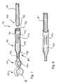
- Fig. 1 is a part of a human skull bone 1 with the auditory canal 2, the middle ear space (tympanic cavity) 4 separated therefrom by the eardrum 3 and the ossicular chain 5 located in the tympanic cavity.
- the ossicle chain 5 includes the hammer 6, the anvil 7 with the long incus process 8, and the stirrup 9 with the stirrup foot plate 10.
- an electromechanical hearing device converter 13 is fixed by means of a positioning and fixing system designated overall by 14.
- the hearing aid converter 13 may, for example, as a piezo transducer for vibratory stimulation of the ossicular chain in particular in the US-A-5,277,694 be known manner, and it is part of an at least partially implantable and preferably fully implantable hearing aid, such as a hearing aid of ENT 1997 Vol. 45, 749-774 known type.
- a vibration transmission path in the form of a biocompatible, mechanically passive coupling arrangement 17 is provided.
- the coupling arrangement 17 is connected to the actively oscillatable output-side driver part 15, and in the implanted state it rests against the coupling point 16 with a coupling end remote from the hearing aid converter 13.
- the coupling arrangement 17 is caused by means of the output-side driver part 15 to vibratory oscillations in the axial direction of the coupling arrangement.
- the audio signals recorded and electrically converted by an input-side transducer (microphone) directly lead to mechanical deflections of the coupling arrangement 17 after electronic amplification in an electronic module of the active hearing system. These deflections correspond to the acoustic information.
- the deflections of the coupling arrangement 17 are forwarded to the ossicular chain 5 of the middle ear or to the stirrup 9, the stirrup base plate 10 or a membrane, not shown, the oval or round window or an artificial window in the cochlea, vestibulum or labyrinth (Gleichissorgan ) completes.
- the deflections of the coupling arrangement thus effect an audiological amplifying effect with a corresponding design of the preprocessing electronic system.
- the coupling assembly 17 has a mechanically fixedly connected to the output side driver part 15 coupling rod 19 which in the embodiment shown in the Essentially has the shape of a straight cylinder along its entire length.
- the coupling rod 19 extends from the mastoid cavity 12, preferably through a natural, if necessary artificially expanded, bone perforation (aditus ad antrum) 21 into the tympanic cavity 4.
- the coupling arrangement 17 further includes a coupling element 22 is connected to the remote from the hearing aid converter 13 end of the coupling rod 19 via a coupling 23 and is coupled via a Ankoppelende at the Ankoppelstelle 16.
- the schematically illustrated coupling 23 comprises two coupling halves, of which a first coupling half has an outer contour with at least approximately the shape of a spherical cap, which is accommodated in an outer contour at least partially complementary inner contour of a second coupling half.
- the first coupling half is preferably integrally formed at the free end of the coupling rod 19.
- the coupling 23 is designed so that it is reversibly pivotable and rotatable by the surgeon during implantation against frictional forces, but is substantially rigid when occurring in the implanted state dynamic forces.
- FIGS. 2 and 3 a coupling arrangement with a coupling 34 is shown, which is designed as a ball joint coupling and the first coupling half 36 has a ball head 80 which can be inserted into a second coupling half 38 in the form of a Kugelaufhahme 79.
- the ball seat 79 has approximately bell-shaped shape with a plurality of slots 26 which extend from one of the first coupling half 36 facing end face 42 substantially perpendicular to the circumferential direction of the ball seat 79.
- spring arms 28 are formed, which can resiliently spring outwards during the coupling and uncoupling operation, wherein an insertion region 30 widening outward in the direction of the end face 42 facilitates the coupling of the ball head 80 to the ball receptacle 79.
- the coupling element 68 is designed as a two-armed lever with the two arms 76 and 77, which is supported in a central region on the short incus extension 69, If the coupling rod end 67 of the arm 76 caused by the coupling rod 19 to move according to the double arrow 71, The coupling element 68 pivots about a pivot point 72 determined by the short incus extension 69.
- a coupling end 73 of the coupling element 68 arranged on the arm 77, which engages with the long anvil extension 8 via a spring clip 74 or the like, is adjusted in accordance with the double arrow 75.
- a desired lever ratio can be adjusted.
- the coupling 34 is not only rotatable and pivotable in situ, it can also be switched on and off at the implantation site, whereby the handling of the device is much easier. After implantation, the adjusted relative position of coupling rod 19 and coupling element 68 is no longer adjusted by the dynamic forces that occur.
- a coupling 82 is provided in the form of a ball joint coupling
- the first coupling half comprises a ball 103 which is integrally connected to the latter at an end remote from the hearing aid converter 13 of a coupling rod 19 '.
- a coupling element 83 is a resilient clip of two connected at 125, preferably welded, spring arms 126 and 127 are used.
- the spring arms 126, 127 form on the one hand a second coupling half in the form of a ball receptacle 121 for the ball 103 of the coupling rod 19 'and on the other hand a receiving opening 86 with an expandable passage 87 for the Zielossikel 8.
- the ball receptacle 121 is provided with an insertion region 84 which widens in the direction of an end face 90, wherein the passage 87 for the target ossicle 8 is placed in a coupling end 100 of the coupling element 83 whose end face 122 is located substantially perpendicular to the end face 90.
- the coupling element 83 can be introduced into the middle ear space 4 through the opening 21 in the rear auditory canal wall 20 by means of the coupling rod 19 'and be positioned such that the expandable passage 87 with the target ossicle, for example the long anvil extension 8, correspondingly Fig. 4 is aligned. Then, the coupling element 83 is depressed and thereby in the direction of arrow 133 in Fig. 5 pivoted with respect to the coupling rod 19 'until the Zielossikel 8 lies under widening of the passage 87 in the receiving opening 86. In this way a secure coupling to the target ossicle is achieved. In the implanted state, the coupling rod 19 'carries out vibrations substantially in the direction of the double arrow 88, wherein the coupling 82 transmits the vibrations rigidly.
- An in Fig. 6 illustrated coupling element 117 comprises two welded at 118 wavy spring arms 119 which form on one side of the joint 118, a ball receptacle 123 for the ball 103 of the coupling rod 19 'and on the other side of this junction the expandable passage 87 and the receiving opening 86 for the Zielossikel ,
- the coupling element 117 can rotate and pivot relative to the coupling rod 19 'according to the arrow group 107 and differs from the coupling element 83 according to the FIGS. 4 and 5 essentially in that the ball receptacle 123 as the second coupling half of a coupling 114 has no section corresponding to the insertion region 84 and accordingly can not be reversibly connected and uncoupled.
- an end face 128 receiving the target particle passage 87 is opposed to the embodiment of FIGS. 4 and 5 approximately parallel to a second coupling half with the ball receptacle 123 limiting end face 130.
- the coupling 114 transmits the dynamic forces occurring in the implanted state rigid.
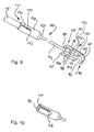
- FIGS. 7 and 8 are a first and a second clutch connected in series, wherein as the first clutch, the clutch 114 of the Fig. 6 is used.
- the ball 103 is connected to a stem 142 of a generally designated 164 intermediate element, which stem 142 is defined via a widening portion 158 on a sleeve 150 a second coupling half 144 of the second clutch 146.
- a first coupling half 148 of the coupling 146 is of a free end of a coupling rod 19 '' is formed, whose second end is connected to the hearing aid transducer 13 and is vibrated by this.
- an insertion region 162 tapering towards the end is provided at the free end of the coupling rod 19 ''.
- the sleeve 150 has in its wall 160 a plurality of substantially longitudinally of the sleeve 150 extending slots 152, which are distributed approximately uniformly around the circumference and end in front of an end face 156 at the free end of the sleeve 150. Between each two adjacent slots 152, a web 154 is formed, which abuts in the sleeve 150 inserted first coupling half 148 in this biased inwardly with predetermined contact pressure.
- the series connection of two clutches has the particular advantage that during implantation, the arrangement can first be divided by loosening the clutch 146 into two assemblies to be handled separately, which are connected by coupling the coupling element 117 by means of its receiving opening 86 on Zielossikel again.
- the coupling 146 can be reversibly coupled and uncoupled by the surgeon while displacing in situ in the longitudinal direction of the sleeve 150 and rotate about the longitudinal axis of the sleeve 150, wherein the design of the coupling 146 is made so that the operator set rotational and translational relative position the two coupling halves 144 and 148 remains stably maintained at the dynamic forces occurring in the implanted state, at least as long as a predetermined minimum insertion depth of the first coupling half 148 in the second coupling half 144 is not exceeded.
- the other Kugelgelenk- and plug-in couplings described below are statically reversible adjustable during implantation against frictional forces, but transmit the occurring in the implanted state, lower dynamic forces rigid.
- FIGS. 9 and 10 is another embodiment of an arrangement illustrated, in which also two series-connected couplings are used, namely designed as a plug-in coupling 171 and a coupling 173 in the form of a ball joint coupling.
- An intermediate element 166 differs from the intermediate element 164 of FIGS. 7 and 8 essentially only in that the second coupling half of the coupling 171 comprises a modified sleeve 168, which with a single slot 170 is provided which extends from one end face 204 at the free end of the sleeve 168 in the sleeve longitudinal direction and terminates in a substantially circular discharge opening 172 which connects the two slot banks 174.
- the plug-in coupling 171 is designed in such a way that the first coupling half 148 provided on the coupling rod 19 'is always pushed into a receptacle 192 of the sleeve 168 so far that the free end of the first coupling half 148 abuts against a depth stop 206 in the interior of the sleeve 168. An optical visual inspection of the plugging operation is possible through the slot 170.
- a coupling element 176 is integrally formed and comprises, as a second coupling half of the coupling 173, a ball seat 184, which is formed by two opposing spring arms 186 and 188, both extending to a coupling-side end 185 of the coupling element 176.
- this U-shaped is extended toward a receiving opening 182 for the Zielossikel, wherein a spring arm 189 opposite leg 193 is connected via a transverse web 191 with the spring arm 186 and a between the leg 193 and the spring arm 189th provided transverse web 187 is formed so that its away from the ball seat 184 outer surface together with an inner surface of a spring clip 180 forms the receiving opening 182.
- the spring clip 180 is formed on the spring arm 186 opposite side of the transverse web 191 on the same and extends initially in thin-walled extension of the spring clip 186 approximately parallel to the leg 193, then to pass into a curved segment 181.
- the free end of the segment 181 terminates essentially at the same height as a side surface 189 of the spring arm 188, so that the target ossicle is introduced approximately vertically with respect to the side surface 189 into the receiving opening 182 present at the coupling end 178 of the coupling element 176.
- the side surface 189 is approximately perpendicular with respect to a front side 185 receiving plane aligned.
- a passage 190 is introduced such that both passages have a common longitudinal axis, which also extends through the center of the ball 103.
- the ball 103 facing end faces of the passages 190 for the ball 103 a defined contact surface, which in the Type of a ball socket can be formed.
- the entire coupling element 176 is preferably made of titanium or a titanium alloy.
- Fig. 11 is an arrangement again, in which as the ball joint coupling the clutch 34 according to the FIGS. 2 and 3 and as a plug-in coupling 171 of the FIGS. 9 and 10 is used, wherein the second coupling half 38 of the coupling 34 is connected to a stem 194, the free end of which forms the first coupling half of the coupling 171.
- the stem 142 connected to the sleeve 168 does not terminate in the ball 103 but merges into a docking end 202 for the target ossicle.
- the docking end 202 includes a belt loop 198 which forms a target ossicle receiving opening 200 and is, for example, layable about the long anvil extension 8.
- titanium or a titanium alloy is preferably used as the material, whereas the belt loop 198 is manufactured in particular from gold or a gold alloy.
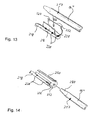
- FIG. 12 plug-in coupling shown differs from the coupling 171 according to the FIGS. 9 and 10 mainly in that a slit 210 inserted in a sleeve 208 does not terminate at its end facing away from an end face 212 in a round relief opening corresponding to the relief opening 172 of the sleeve 168 but in a transverse slit 214 mounted substantially perpendicular to the slit 210.
- FIGS. 13 to 17 played. This will be in a plug-in coupling Fig. 13 a formed at a free end of a coupling rod 19 '''first coupling half 217 in the direction of the arrow 226 substantially perpendicular to a longitudinal axis of a formed as a sleeve 216 second coupling half.
- the sleeve 216 is provided with a longitudinally continuous slot, wherein a wall 228 of the sleeve 216 is curved in the region of Schlitzufern 222 on both sides of the slot to the outside, so that an insertion portion 224 results when coupling the first Clutch half 217 interacts with an outer wall thereof and facilitates springing of the sleeve 216.
- the sleeve 216 is at its the slot approximately diametrically opposite outside a stem 218 of the coupling arrangement via connection points 220 connected, in particular welded or soldered.
- plug-in coupling comprises as a second coupling half a sleeve 230 with a continuous slot, but in contrast to the sleeve 216 according to Fig. 13 an outwardly widening insertion region 232 is provided on an end face 236 of a free end of the sleeve 230 and the wall of the sleeve 230 otherwise has approximately circular cylindrical shape.
- the coupling process of the first coupling half 217 to the sleeve 230 takes place essentially in the longitudinal direction of the sleeve, the insertion region 232 of the sleeve 230 cooperating with a tapered insertion portion 234 formed at the free end of the first coupling half 217 and facilitating springing up of the sleeve 230.
- FIGS. 15 to 17 show another modified plug-in coupling, extending from the coupling 146 according to the FIGS. 7 and 8 essentially only by the configuration of slots 240 in a wall 248 of the formed as a sleeve 238 second coupling half differs, as the slots 152 in the sleeve 150 after the FIGS. 7 and 8
- the slots 240 in the sleeve 238 extend substantially in the longitudinal direction of the sleeve and terminate in front of a front side 242 of the sleeve 238.
- Fig. 18 schematically an implanted passive hearing system is shown, in which the eardrum 3 is used as stimulable to mechanical vibrations output side driver part.
- the eardrum 3 On the eardrum 3 there is a total of 135 designated TORP prosthesis (total ossicular replacement prosthesis) with a head 136, which has a rounded surface.
- TORP prosthesis total ossicular replacement prosthesis
- a coupling rod 139 connects, which may be integrally connected to the head 136 and the free end of a as Ball joint coupling formed coupling 140 is connected to a free end of a coupling element 137.
- a coupling end 138 of the coupling element 137 which is remote from the coupling 140, is coupled to the stirrup head 141.
- the coupling 140 allows during implantation a reversible static pivoting and rotation of the coupling element 137 and coupling rod 139 with respect to each other, but transmits rigidly introduced in the implanted state of the eardrum 3 in the clutch dynamic forces.
- the head 136, the coupling rod 139 and the coupling element 137 suitably consist of an implantable metallic or ceramic material.
- all known biocompatible metals and their alloys can be used as materials for the coupling rod, the coupling element, the coupling as well as the interposed as needed between two couplings, especially implantable titanium, in particular pure titanium with a purity> 99.6%.
- implantable titanium in particular pure titanium with a purity> 99.6%.
- platinum, niobium or tantalum or alloys of titanium, platinum, niobium or tantalum are suitable.
- the coupling rod or other of the above-mentioned components but also of an implantable ceramic material, in particular alumina exist.
- long-term implantable plastics may also be provided, such as inter alia cross-linked silicones, polyurethanes, PTFE, FEP, polycarbonates and the like, which may optionally be fiber-reinforced, in particular carbon fiber-reinforced, but at least one in the implanted state at the coupling site on the ossicular chain , the stirrup footplate or a portion of the coupling element adjacent to the round window or an artificial window in the cochlea, vestibulum or labyrinth (equilibrium organ) for low-loss, ie essentially sound-hard, vibration introduction is designed in the Ankoppelstelle and thus has little entropy elasticity.
- This adjoining the Ankoppelstelle portion of the coupling element is preferably made of one of said metallic or ceramic materials or is executed in gold or a gold alloy.
Description
- Die Erfindung betrifft eine implantierbare Anordnung zum mechanischen Ankoppeln eines zu mechanischen Schwingungen anregbaren ausgangsseitigen Treiberteils eines aktiven oder passiven Hörsystems an eine vorgewählte Ankoppelstelle an der Ossikelkette, der Steigbügelfußplatte oder einer das runde Fenster oder ein artifizielles Fenster in der Cochlea, im Vestibulum oder im Labyrinth (Gleichgewichtsorgan) abschließenden Membran über eine Koppelanordnung, die eine vom Treiberteil in mechanische Schwingungen versetzbare Koppelstange sowie ein mit der vorgewählten Ankoppelstelle in Verbindung bringbares Koppelelement aufweist, wobei die Koppelstange und das Koppelelement über wenigstens eine Kupplung miteinander verbunden sind und zumindest ein im implantierten Zustand an der Ankoppelstelle anliegender Abschnitt des Koppelelements zur verlustarmen, d.h. im Wesentlichen schallharten, Schwingungseinleitung in die Ankoppelstelle ausgelegt ist.
- Es sind teil- oder vollimplantierbare aktive Hörsysteme für eine direkte mechanische Stimulation bekannt. Bei solchen Hörsystemen wird das Schallsignal mit einem Sensor (Mikrofon) in ein elektrisches Signal umgewandelt und in einer elektronischen Signalverarbeitungsstufe verstärkt; dieses verstärkte elektrische Signal wird einem implantierten elektromechanischen Wandler zugeführt, dessen ausgangsseitige mechanische Schwingungen unmittelbar, also mit direktem mechanischen Kontakt, dem Mittel- beziehungsweise Innenohr zugeführt werden. Dies gilt unabhängig davon, ob eine reine Innenohrschwerhörigkeit bei vollständig intaktem Mittelohr oder eine kombinierte Schwerhörigkeit (Mittel- und Innenohr geschädigt) rehabilitiert werden soll. Daher sind in der jüngeren wissenschaftlichen und Patent-Literatur implantierbare elektromechanische Wandler sowie Verfahren zur direkten Ankopplung der mechanischen Wandlerschwingungen an das intakte Mittelohr beziehungsweise das Innenohr zur Rehabilitation einer reinen Innenohrschwerhörigkeit sowie auch an verbleibende Ossikel des Mittelohres bei artifiziell oder pathologisch verändertem Mittelohr zur Versorgung einer Schalleitungsschwerhörigkeit sowie deren Kombinationen beschrieben worden.
- Als elektromechanisches Wandlerverfahren kommen grundsätzlich alle physikalischen Wandlungsprinzipien in Frage wie elektromagnetisch, elektrodynamisch, magnetostriktiv, dielektrisch und piezoelektrisch. Verschiedene Forschungsgruppen haben sich in den letzten Jahren im wesentlichen auf zwei dieser Verfahren konzentriert: elektromagnetisch und piezoelektrisch. Eine Übersicht über diese Wandlervarianten findet sich bei Zenner und Leysieffer (HNO 1997 Vol. 45, 749 - 774).
- Beim piezoelektrischen Verfahren ist eine mechanisch direkte Kopplung der ausgangsseitigen Wandlerschwingungen an die Mittelohrossikel oder direkt an das ovale Fenster notwendig. Beim elektromagnetischen Prinzip kann die Kraftkopplung einerseits über einen Luftspalt erfolgen ("kontaldos"), das heißt, nur ein Permanentmagnet wird durch dauerhafte Fixation in direkten mechanischen Kontakt mit einem Mittelohrossikel gebracht. Andererseits besteht die Möglichkeit, den Wandler vollständig in einem Gehäuse zu realisieren (wobei Spule und Magnet mit kleinstmöglichem Luftspalt gekoppelt sind) und die ausgangsseitigen Schwingungen über ein mechanisch steifes Koppelelement mit direktem Kontakt auf die Mittelohrossikel zu übertragen (Leysieffer et al. 1997 (HNO 1997, Vol. 45, pp. 792-800).
- In der Patentliteratur finden sich einige der oben genannten Realisierungsvarianten sowohl elektromagnetischer wie auch piezoelektrischer Hörgerätewandler:
US-A-5 707 338 (Adams et al. ),WO 98/06235 (Adams et al. WO 98/06238 (Adams et al. WO 98/06236 (Kroll et al. WO 98/06237 (Bushek et al. US-A-5 554 096 (Ball ),US-A-3 712 962 (Epley ),US-A-3 870 832 (Fredrickson ),US-A-5 277 694 (Leysieffer et al. ),DE-C-198 40 211 (Leysieffer ),DE-A-198 40 212.0 (Leysieffer ),US-A-5 015 224 (Maniglia ),US-A-3 882 285 (Nunley ),US-A-4 850 962 (Schaefer ). - Das teilimplantierbare, piezoelektrische Hörsystem der japanischen Gruppe um Suzuki und Yanigahara setzt für eine Implantation des Wandlers das Fehlen der Mittelohrossikel und eine freie Paukenhöhle voraus, um das Piezoelement an den Stapes ankoppeln zu können (Yanigahara et al.: Efficacy of the partially implantable middle ear implant in middle and inner ear disorders. Adv. Audiol.., Vol. 4, Karger Basel (1988), pp. 149-159. SUZUKI et al.: Implantation of partially implantable middle ear implant and the indication. Adv. Audiol., Vol. 4, Karger Basel (1988), pp. 160-166). Ebenso wird bei dem Verfahren eines implantierbaren Hörsystems für Innenohrschwerhörige nach
US-A-4 850 962 (Schaefer ) grundsätzlich der Amboss entfernt, um ein piezoelektrisches Wandlerelement an den Stapes ankoppeln zu können. Dies gilt im wesentlichen auch für weitere Entwicklungen, die auf der SCHAEFER-Technologie basieren und in den oben genannten Patentschriften dokumentiert sind (US-A-5 707 338 ,WO 98/06235 WO 98/06238 WO 98/06236 WO 98/06237 - Der elektromagnetische Wandler nach Ball ("Floating Mass Transducer FMT",
US-A-5 624 376 ,US-A-5 554 096 ) wird dagegen bei intaktem Mittelohr mit Titanclips direkt an dem langen Fortsatz des Amboss fixiert. Der elektromagnetische Wandler des teilimplantierbaren Systems nach FREDRICKSON (FREDRICKSON et al.: Ongoing investigations into an implantable elektromagnetic hearing aid for moderate to severe sensorineural hearing loss. Otolaryngologic Clinics Of Nord America, Vol. 28/1 (1995), pp. 107-121) wird bei ebenfalls intakter Ossikelkette des Mittelohres mechanisch direkt an den Ambosskörper gekoppelt. Das Gleiche gilt für die piezoelektrischen und elektromagnetischen Wandler nach LEYSIEFFER (Leysieffer et al.: Ein implantierbarer piezoelektrischer Hörgerätewandler für Innenohrschwerhörige. HNO 1997/45, pp. 792-800,DE 41 04 358.8 ,DE 198 40 211.2 ,DE 198 40 212,0 ). Auch bei dem elektromagnetischen Wandlersystem nach MANIGLIA (Manigila et al.: Contactless semi-implantable electromagnetic middle ear device for the treatment of senrorineural hearing loss. Otolaryngologic Clinics Of Nord America, Vol. 28/1 (1995), pp. 121-141) wird bei intakter Ossikelkette ein Permanentmagnet mechanisch an der Ossikelkette dauerhaft fixiert, der jedoch über eine Luftspaltkopplung von einer Spule mechanisch angetrieben wird. - Bei den beschriebenen Wandler- und Ankopplungsvarianten sind grundsätzlich zwei Implantationsprinzipien zu unterscheiden:
- a) Einerseits befindet sich der elektromechanische Wandler mit seinem aktiven Wandlerelement selbst im Mittelohrbereich in der Paukenhöhle und ist dort direkt mit einem Ossikel oder dem Innenohr verbunden (
US-A-4 850 962 ,US-A-5 015 225 ,US-A-5 707 338 ,WO 98/06235 WO 98/06238 WO 98/06236 WO 98/06237 US-A-5 624 376 ,US-A-5 554 096 ). - b) Andererseits befindet sich der elektromechanische Wandler mit seinem aktiven Wandlerelement außerhalb des Mittelohrbereiches in einer artifiziell geschaffenen Mastoidhöhle; die ausgangsseitigen mechanischen Schwingungen werden dann mittels mechanisch passiver Koppelelemente über geeignete operative Zugänge (natürlicher aditus ad antrum, Eröffnung des chorda-facialis-Winkels oder über eine artifizielle Bohrung vom Mastoid aus) zum Mittel- beziehungsweise Innenohr übertragen (FREDRICKSON et al.: Ongoing investigations into an implantable elektromagnetic hearing aid for moderate to severe sensorineural hearing loss. Otolaryngologic Clinics Of Nord America, Vol. 28/1 (1995), pp. 107-121;
DE 41 04 358.8 , ältereAnmeldung DE 198 40 211.2 , ältereAnmeldung DE 198 40 212.0 ). - Bei den Varianten nach a) kann der Wandler als sogenannter "Floating Mass"-Wandler ausgeführt sein, d.h., das Wandlerelement benötig keine "Reaktio" über eine feste Verschraubung mit dem Schädelknochen, sondern es schwingt aufgrund von Massenträgheitsgesetzen mit seinem Wandlergehäuse und überträgt diese direkt auf ein Mittelohrossikel (
US-A-5 624 376 ,US-A-5 554 096 ,US-A-5 707 338 ,WO 98/06236 - Bei den Wandlervarianten nach b) wird das Wandlergehäuse mit implantierbaren Positionier- und Fixationssystemen an der Schädelkalotte befestigt (vorteilhafte Ausführung
DE-A-196 18 964 entsprechendUS-A-5 788 711 ). Sowohl bei dem teilimplantierbaren System nach FREDRICKSON (Ongoing investigations into an implantable elektromagnetic hearing aid for moderate to severe sensorineural hearing loss. Otolaryngologic Clinics Of North America, Vol. 28/1 (1995), pp. 107-121) wie auch bei dem vollimplantierbaren Hörsystem nach LEYSIEFFER und ZENNER (HNO 1998, Vol. 46, 853-863 und 844-852) wird bei der Ankopplung des schwingenden Treiberteils an den Ambosskörper zur dauerhaften und mechanisch sicheren Schwingungsübertragung davon ausgegangen, dass die Spitze der Koppelstange, die in die laserinduzierte Vertiefung des Mittelohrossikels eingebracht wird, langfristig eine Osseointegration erfährt, das heißt, die Koppelstange verwächst fest mit dem Ossikel und gewährleistet so eine sichere Übertragung dynamischer Druck- und Zugkräfte. Dieser Langzeiteffekt ist zur Zeit jedoch noch nicht wissenschaftlich nachgewiesen beziehungsweise gesichert. Weiterhin besteht bei dieser Ankopplungsart bei einem technischen Wandlerdefekt der Nachteil, dass eine Entkopplung vom Ossikel zur Entfernung des Wandlers nur mit mechanisch basierten operativen Methoden vorgenommen werden kann, was eine erhebliche Gefährdung des Mittelohres und insbesondere des Innenohres bedeuten kann. - Der wesentliche Vorteil dieser Wandlerausführungsformen nach b) besteht jedoch darin, dass das Mittelohr weitgehend frei bleibt und der Koppelzugang zum Mittelohr ohne größeres Gefährdungspotential des nervus facialis erfolgen kann. Ein vorzugsweises operatives Verfahren hierzu ist in
US-A-6 077 215 beschrieben. Grundlegende vorteilhafte Formen passiver Koppelelemente zur Übertragung der ausgangsseitigen Wandlerschwingungen vom Mastoid aus zum Mittel- beziehungsweise Innenohr sind inEP-A-0 499 940 sowie inEP-A-0 901 779 und in HNO 1998 Vol. 46, 27-37 - Lehner et al.: "Kaltfließende Elemente zur Ankopplung eines implantierbaren Hörgerätewandlers an Gehörknöchelchen oder Perilymphe" beschrieben. Dabei handelt es sich insbesondere um Koppelelemente aus Gold, vorzugsweise weichgeglühtem Feingold, in Form eines C-Bandes für den langen Ambossfortsatz, einer Bandschlaufe für den langen Ambossfortsatz und eines Glöckchens für das Steigbügelköpfchen, wobei sich diese Koppelelemente unter Verwendung von ohrchirurgischen Standardinstrumenten ankoppeln und erforderlichenfalls auch wieder lösen lassen. - Die ältere
EP-Patentanmeldung 00 105 227.3 - Aus der
WO 99/08475 - Eine Anordnung nach dem Oberbegriff des Anspruchs 1 ist in der
DE 197 38 587 C1 beschrieben, bei der die erste Kupplungshälfte im Wesentlichen stabförmig und die zweite Kupplungshälfte etwa hülsenförmig ausgebildet ist, wobei durch Verschieben und/oder Verdrehen der beiden Kupplungshälften die Relativlage von Koppelstange und Koppelelement am Implantationsort in situ einstellbar ist. Die beiden Bauteile werden in der eingestellten Relativlage zuverlässig und langzeitstabil fixiert, indem mittels eines Crimpwerkzeugs eine Crimpkraft auf die hülsenförmige zweite Kupplungshälfte aufgebracht wird, wodurch sich diese plastisch kaltverformt, wohingegen die stabförmige erste Kupplungshälfte unter der wirkenden Crimpkraft keiner plastischen Kaltverformung unterzogen wird. - Neben den erläuterten aktiven Hörsystemen sind auch passive Hörsysteme in Form von Prothesen als Totalersatz (TORP = total ossicular replacement prosthesis) oder als Teilersatz (PORP = partial ossicular replacement prosthesis) für die Ossikelkette bekannt (D. I. Bojrab et al. "Ossiculoplasty with composite prostheses" in Otolaryngologic Clinics of North America, Vol. 27, No. 4, 1994, pp. 759-776). Bei solchen passiven Systemen bildet das Trommelfell selbst oder ein Bereich des noch intakten, dem Trommelfell zugewandten "Rests" der Ossikelkette das ausgangsseitige Treiberteil. So ist in der
US 5 370 689 eine passive Mittelohrprothese als Stapesersatz offenbart, welche einen länglichen Stababschnitt umfasst, dessen eines Ende mit der Stapesfußplatte verbunden ist. Am anderen Ende des Stababschnitts ist ein offener Ring angeformt, der über das freie Ende des langen Ambossfortsatzes geschoben wird. Die Bewegung des vom langen Ambossfortsatz angetriebenen Stapesersatzes wird mittels einer Zugvorrichtung modifiziert, an welcher der Stapesmuskel angreift. Zu diesem Zweck ist die Zugvorrichtung auf den Stababschnitt aufgeschoben, wobei die Passung zwischen dem Stababschnitt und der Innenfläche der Zugvorrichtung so gewählt ist, dass beide Teile während der Implantation relativ zueinander bewegt werden können, wohingegen eine unerwünschte axiale oder rotatorische Bewegung der Zugvorrichtung nach der Implantation ausgeschlossen ist. - Der vorliegenden Erfindung liegt die Aufgabe zugrunde, eine Anordnung der eingangs genannten Art zu schaffen, die es erlaubt, die Relativlage der beiden Kupplungshälften der Kupplung am Implantationsort in situ möglichst feinfühlig in vielen Freiheitsgraden einzustellen, wobei die eingestellte Relativlage nach der Implantation auf einfache Weise zuverlässig und langzeitstabil aufrechterhalten bleibt.
- Diese Aufgabe wird bei einer Anordnung nach dem Oberbegriff des Anspruchs 1 dadurch gelöst, dass eine erste Kupplungshälfte der Kupplung eine Außenkontur mit mindestens näherungsweise der Gestalt einer Kugelkalotte aufweist, die in einer zur Außenkontur wenigstens teilweise komplementären Innenkontur einer zweiten Kupplungshälfte aufnehmbar ist, wobei die Kupplung gegen Reibkräfte reversibel verschwenk- und/oder drehbar, jedoch bei im implantierten Zustand auftretenden dynamischen Kräften im Wesentlichen starr ist.
- Die erfindungsgemäße Anordnung sorgt auf besonders einfache und gleichwohl zuverlässige Weise dafür, dass die beiden Kupplungshälften während der Implantation in eine gewünschte Relativlage gebracht werden können, wobei dennoch nach der Implantation die von dem Treiberteil ausgehenden, in die erste oder zweite Kupplungshälfte eingeleiteten mechanischen Schwingungen im Wesentlichen starr auf die jeweils andere Kupplungshälfte übertragen werden, ohne dass es hierfür irgendeines zusätzlichen Arbeitsschritts bedarf Ausgehend von den vorgegebenen, bekannten dynamischen Kräften, die im implantierten Zustand von der Kupplung übertragen werden müssen, und den höheren Kräften, die im Zuge der Implantation vom Operateur typischerweise aufgebracht werden, wählt man die die Eigenschaften der Paarung der beiden Kupplungshälften wesentlich beeinflussenden Parameter wie Werkstoff, Oberflächenrauheit (Mikrogeometrie) und Passung (Makrogeometrie) dergestalt, dass insbesondere der Stick-Slip-Effekt und die Reibungskräfte zwischen den Kupplungshälften bei den als Zweites genannten Kräften ein problemloses statisch reversibles Verstellen der Kupplung während der Implantation ermöglichen, wohingegen die Kupplung bei den zuerst genannten dynamischen Kräften starr ist.
- Vorteilhafte Weiterbildungen der Erfindung sind Gegenstand der Unteransprüche.
- Die Handhabung der Anordnung lässt sich wesentlich vereinfachen, wenn die Kupplung für ein reversibles An- und Abkuppeln ausgelegt ist.
- Die zweite Kupplungshälfte der Kupplung kann zumindest zwei Federarme aufweisen, mittels derer die erste Kupplungshälfte wenigstens teilweise umgreifbar ist. Die Federarme, die stoffschlüssig, beispielsweise durch Löten, Schweißen oder dergleichen, verbunden oder aber auch einstückig ausgeführt sein können, sind vorzugsweise nach innen federnd vorgespannt an die erste Kupplungshälfte anlegbar.
- Ferner kann die zweite Kupplungshälfte der Kupplung auch etwa glockenförmige Gestalt aufweisen und insbesondere mehrere im Wesentlichen senkrecht zur Umfangsrichtung verlaufende Schlitze umfassen, die sich bis zu einer der ersten Kupplungshälfte zugewandten Stirnseite der zweiten Kupplungshälfte erstrecken. Auf diese Weise lässt sich die erste Kupplungshälfte sicher in der zweiten Kupplungshälfte aufnehmen. Gleichzeitig wird eine ausreichende Flexibilität der zweiten Kupplungshälfte für ein reversibles An- und Abkoppeln geschaffen.
- In vorteilhafter weiterer Ausgestaltung der Erfindung ist eine zweite Kupplung vorgesehen, die gegen Reibkräfte reversibel linear und/oder rotatorisch verstellbar, jedoch bei im implantierten Zustand auftretenden dynamischen Kräften im Wesentlichen starr ist, wobei eine erste Kupplungshälfte eine Außenkontur mit mindestens näherungsweise zylindrischer, vorzugsweise kreiszylindrischer, Gestalt hat, die in einer zur Außenkontur wenigstens teilweise komplementären Innenkontur einer zweiten Kupplungshälfte aufnehmbar ist. Die zweite Kupplung ist vorzugsweise für ein reversibles An- und Abkoppeln ausgelegt und lässt sich sowohl zwischen der Kupplung, bei der die erste Kupplungshälfte näherungsweise die Gestalt einer Kugelkalotte hat (erste Kupplung), und dem Treiberteil als auch zwischen der ersten Kupplung und der Ankoppelstelle positionieren. Es ist bevorzugt, dass im implantierten Zustand eine Übertragung von dynamischen Kräften zwischen den beiden Kupplungshälften der zweiten Kupplung im Wesentlichen in Richtung der Längsachse der ersten Kupplungshälfte erfolgt.
- Ein besonders einfacher Aufbau ergibt sich, wenn die zweite Kupplungshälfte der zweiten Kupplung als Hülse ausgebildet ist. Die Hülse kann wenigstens einen im Wesentlichen in ihrer Längsrichtung verlaufenden Schlitz, der sich zumindest über einen Teil der Hülsenlänge erstreckt, aufweisen. Ferner kann sich zur Erhöhung der Flexibilität wenigstens ein Schlitz bis zu einer der ersten Kupplungshälfte zugewandten Stirnseite der Hülse erstrecken.
- Erstreckt sich ein Schlitz über die gesamte Hülsenlänge, so kann die Wandung im Bereich der beiden Schlitzufer des durchgehenden Schlitzes nach außen weisen und einen Einführabschnitt bilden, in den die erste Kupplungshälfte im Wesentlichen senkrecht zu ihrer Längsachse einführbar ist.
- Wenigstens ein Schlitz kann zumindest einseitig in einer die Elastizität der zweiten Kupplungshälfte sowie deren Sicherheit gegen Beschädigung erhöhenden Entlastungsöffnung enden, deren Begrenzungslinie die beiden Schlitzufer verbindet, wobei die Entlastungsöffnung quer zur Schlitzrichtung eine Abmessung aufweist, die größer als diejenige des Schlitzes ist.
- Die Begrenzungslinie mindestens einer Entlastungsöffnung kann die Schlitzufer bogenförmig, vorzugsweise im Wesentlichen kreisbogenförmig, verbinden oder aber in Form eines im Wesentlichen senkrecht zum Schlitz verlaufenden Querschlitzes ausgebildet sein.
- Bei einer weiteren Ausführungsform der Erfindung ist wenigstens ein Abschnitt einer Wandung der Hülse der zweiten Kupplung nach innen federnd vorgespannt an die erste Kupplungshälfte anlegbar. Weiterhin können wenigstens zwei Schlitze vorgesehen sein, wobei zumindest ein sich zwischen zwei benachbarten Schlitzen befindender Abschnitt einer Wandung der Hülse nach innen federnd vorgespannt an die erste Kupplungshälfte anlegbar ist. Dabei kann vorgesehen sein, wenigstens zwei benachbarte Schlitze endseitig insbesondere im Wesentlichen U-förmig miteinander zu verbinden, so dass eine federnde Zunge entsteht.
- Zur Erleichterung des An- und Abkoppelvorgangs lässt sich die Außenkontur der ersten Kupplungshälfte der zweiten Kupplung im Bereich ihres der zweiten Kupplungshälfte zugewandten Endes mit einem sich in Richtung auf das Ende hin verjüngenden Einführbereich versehen.
- Zu diesem Zweck kann auch die Innenkontur der zweiten Kupplungshälfte mindestens einer Kupplung im Bereich ihres der ersten Kupplungshälfte zugewandten Endes mit einem sich in Richtung auf das Ende hin erweiternden Einführbereich versehen sein. Dies gilt sowohl für die erste als auch für die zweite Kupplung.
- Mindestens eine erste und/oder eine zweite Kupplungshälfte wenigstens einer Kupplung lassen sich überdies vorteilhaft mit dem zugeordneten Koppelelement oder der zugeordneten Koppelstange einstückig verbinden.
- Die erfindungsgemäße Anordnung kann Teil eines aktiven, teil- oder vollimplantierbaren Hörsystems sein, bei dem das ausgangsseitige Treiberteil ein schwingfähiges Teil, insbesondere eine schwingfähige Membran, eines elektromechanischen Hörgeratewandlers ist. Die Anordnung nach der Erfindung kann aber auch Teil eines passiven Hörsystems, insbesondere einer Teil- oder Voll-Mittelohrprothese, sein, bei dem im implantierten Zustand das Trommelfell als ausgangsseitiges Treiberteil genutzt ist.
- Bevorzugte Ausführungsbeispiele der Anordnung nach der Erfindung werden nachstehend anhand der beiliegenden Zeichnungen naher erläutert. Es zeigen:
- Fig. 1
- in vergrößertem Maßstab schematisch einen implantierten Hörgerätewandler sowie eine Koppelanordnung mit einer vom Hörgerätewandler angetriebenen Koppelstange und einem Koppelelement, welches letzteres zum einen über eine Kupplung mit der Koppelstange verbunden und zum anderen an die Ossikelkette angekoppelt ist;
- Fig. 2
- in noch größerem Maßstab eine schematische perspektivische Darstellung des Hörgerätewandlers nach
Fig. 1 , der über eine abgewandelte Koppelanordnung an den Ambosskörper angekoppelt ist; - Fig. 3
- eine schematische vergrößerte Ansicht des mit einem Kreis III versehenen Bereichs der
Fig. 2 ; - Fign. 4 und 5
- schematische Darstellungen einer Ausführungsform, bei der die Kupplung zwischen der Koppelstange und dem Koppelelement als Kugelgelenkkupplung ausgebildet ist;
- Fig. 6
- eine schematische perspektivische Darstellung eines abgewandelten Koppelelements mit geänderter Kugelgelenkkupplung;
- Fign. 7 bis 11
- schematische perspektivische Darstellungen von abgewandelten Koppelanordnungen mit zwei Kupplungen, wobei eine erste Kupplung als Kugelgelenkkupplung und eine zweite Kupplung als Steckkupplung ausgebildet ist;
- Fign. 12 bis 17
- schematische perspektivische Darstellungen weiterer abgewandelter Steckkupplungen; und
- Fig. 18
- eine schematische perspektivische Darstellung einer erfindungsgemäßen passiven Mittelohrprothese mit Kugelgelenkkupplung.
- In
Fig. 1 ist ein Teil eines menschlichen Schädelknochens 1 mit dem Gehörgang 2, dem davon durch das Trommelfell 3 abgetrennten Mittelohrraum (Paukenhöhle) 4 und der in der Paukenhöhle befindlichen Ossikelkette 5 dargestellt. Zu der Ossikelkette 5 gehören der Hammer 6, der Amboss 7 mit dem langen Ambossfortsatz 8 sowie der Steigbügel 9 mit der Steigbügelfußplatte 10. In einer artifiziellen Mastoidhöhle 12 ist ein elektromechanischer Hörgerätewandler 13 mittels eines insgesamt mit 14 bezeichneten Positionier- und Fixiersystems fixiert. Der Hörgerätewandler 13 kann beispielsweise als Piezowandler zur vibratorischen Stimulation der Ossikelkette insbesondere in der ausUS-A-5 277 694 bekannten Weise aufgebaut sein, und er ist Bestandteil eines mindestens teilimplantierbaren und vorzugsweise vollimplantierbaren Hörgerätes, beispielsweise eines Hörgerätes der aus HNO 1997 Vol. 45, 749 - 774 bekannten Art. - Zum mechanischen Ankoppeln eines zu mechanischen Schwingungen anregbaren, in
Fig. 1 nur schematisch angedeuteten ausgangsseitigen Treiberteils 15 des Hörgerätewandlers 13, insbesondere einer schwingfähigen Membran dieses Wandlers, an eine vorgewählte Ankoppelstelle 16 an der Ossikelkette 5, beispielsweise an den "glatten" Körper des Ambosses 7, von Mastoidseite aus, ist ein Schwingungsübertragungsweg in Form einer biokompatiblen, mechanisch passiven Koppelanordnung 17 vorgesehen. Die Koppelanordnung 17 ist mit dem aktiv schwingfähigen ausgangsseitigen Treiberteil 15 verbunden, und sie liegt im implantierten Zustand mit einem von dem Hörgerätewandler 13 abliegenden Ankoppelende an der Ankoppelstelle 16 an. Wird an den Hörgerätewandler 13 eine elektrische Spannung angelegt, wird die Koppelanordnung 17 mittels des ausgangsseitigen Treiberteils 15 zu vibratorischen Schwingungen in Axialrichtung der Koppelanordnung veranlasst. Infolgedessen führen die von einem (nicht dargestellten) eingangsseitigen Wandler (Mikrofon) aufgenommenen und elektrisch gewandelten Audiosignale nach elektronischer Verstärkung in einem Elektronikmodul des aktiven Hörsystems unmittelbar zu mechanischen Auslenkungen der Koppelanordnung 17. Diese Auslenkungen entsprechen der akustischen Information. Die Auslenkungen der Koppelanordnung 17 werden an die Ossikelkette 5 des Mittelohrs bzw. an den Steigbügel 9, die Steigbügelfußplatte 10 oder eine nicht dargestellte Membran weitergeleitet, die das ovale beziehungsweise runde Fenster oder ein artifizielles Fenster in der Cochlea, im Vestibulum oder im Labyrinth (Gleichgewichtsorgan) abschließt. Die Auslenkungen der Koppelanordnung bewirken so bei entsprechender Auslegung des vorverarbeitenden elektronischen Systems einen audiologischen Verstärkungseffekt. - Die Koppelanordnung 17 weist eine mit dem ausgangsseitigen Treiberteil 15 mechanisch fest verbundene Koppelstange 19 auf, die bei der gezeigten Ausführungsform im Wesentlichen auf ihrer gesamten Länge die Gestalt eines geraden Zylinders hat. Die Koppelstange 19 reicht im implantierten Zustand von der Mastoidhöhle 12 aus bevorzugt durch einen in der hinteren Gehörgangswand 20 befindlichen natürlichen, erforderlichenfalls artifiziell erweiterten Knochendurchbruch (Aditus ad antrum) 21 hindurch in die Paukenhöhle 4. Zu der Koppelanordnung 17 gehört ferner ein Koppelelement 22, das mit dem von dem Hörgerätewandler 13 abliegenden Ende der Koppelstange 19 über eine Kupplung 23 verbunden und über ein Ankoppelende an der Ankoppelstelle 16 angekoppelt ist.
- Die schematisch dargestellte Kupplung 23 umfasst zwei Kupplungshälften, von denen eine erste Kupplungshälfte eine Außenkontur mit mindestens näherungsweise der Gestalt einer Kugelkalotte aufweist, die in einer zur Außenkontur wenigstens teilweise komplementären Innenkontur einer zweiten Kupplungshälfte aufnehmbar ist. Die erste Kupplungshälfte ist am freien Ende der Koppelstange 19 vorzugsweise einstückig angeformt. Dabei ist die Kupplung 23 so ausgebildet, dass sie vom Operateur bei der Implantation gegen Reibkräfte reversibel verschwenk- und drehbar jedoch bei im implantierten Zustand auftretenden dynamischen Kräften im Wesentlichen starr ist. Somit ist eine feinfühlige Anpassung der Relativlage von Koppelstange 19 und Koppelelement 22 an die Gegebenheiten des Implantationsorts in situ möglich, wobei sich die einmal eingestellte Relativlage nach der Implantation durch die dann auftretenden dynamischen Kräfte nicht mehr verstellt.
- In den
Fign. 2 und 3 ist eine Koppelanordnung mit einer Kupplung 34 gezeigt, die als Kugelgelenkkupplung ausgebildet ist und deren erste Kupplungshälfte 36 einen Kugelkopf 80 aufweist, der in eine zweite Kupplungshälfte 38 in Form einer Kugelaufhahme 79 eingeführt werden kann. Die Kugelaufnahme 79 besitzt etwa glockenförmige Gestalt mit mehreren Schlitzen 26, die sich von einer der ersten Kupplungshälfte 36 zugewandten Stirnseite 42 aus im Wesentlichen senkrecht zur Umfangsrichtung der Kugelaufnahme 79 erstrecken. Auf diese Weise werden Federarme 28 gebildet, die beim An- und Abkuppelvorgang reversibel nach außen federn können, wobei ein sich in Richtung auf die Stirnseite 42 nach außen erweiternder Einführbereich 30 das Ankuppeln des Kugelkopfs 80 an der Kugelaufnahme 79 erleichtert. - Während der Kugelkopf 80 einstückig mit der Koppelstange 19 ausgebildet ist, geht die Kugelaufnahme 79 über ein Anschlussstück 25 in ein koppelstangenseitiges Ende 67 eines Koppelelements 68 über. Das Koppelelement 68 ist als zweiarmiger Hebel mit den beiden Armen 76 und 77 ausgebildet, der sich in einem mittleren Bereich an dem kurzen Ambossfortsatz 69 abstützt, Wird das koppelstangenseitige Ende 67 des Arms 76 mittels der Koppelstange 19 zu einer Bewegung entsprechend dem Doppelpfeil 71 veranlasst, schwenkt das Koppelelement 68 um einen von dem kurzen Ambossfortsatz 69 bestimmten Drehpunkt 72. Dadurch wird ein am Arm 77 angeordnetes Ankoppelende 73 des Koppelelements 68, das mit dem langen Ambossfortsatz 8 über eine Federklammer 74 oder dergleichen in Eingriff steht, gemäß dem Doppelpfeil 75 verstellt. Durch entsprechende Bemessung der relativen Längen der Arme 76 und 77 des Koppelelements 68 kann ein gewünschtes Hebelverhältnis eingestellt werden. Die Kupplung 34 ist in situ nicht nur dreh- und schwenkbar, sie kann am Implantationsort auch an- und abgekuppelt werden, wodurch sich die Handhabbarkeit der Vorrichtung wesentlich erleichtert. Nach der Implantation wird die eingestellte Relativlage von Koppelstange 19 und Koppelelement 68 durch die auftretenden dynamischen Kräfte nicht mehr verstellt.
- Bei einer abgewandelten Ausführungsform gemäß den
Fign. 4 und 5 ist eine Kupplung 82 in Form einer Kugelgelenkkupplung vorgesehen, deren erste Kupplungshälfte eine Kugel 103 umfasst, die an einem dem Hörgerätewandler 13 abgewandten Ende einer Koppelstange 19' einstückig mit der letzteren verbunden ist. Als Koppelelement 83 kommt eine federnde Klammer aus zwei bei 125 miteinander verbundenen, vorzugsweise verschweißten, Federarmen 126 und 127 zum Einsatz. Die Federarme 126, 127 bilden einerseits eine zweite Kupplungshälfte in Form einer Kugelaufnahme 121 für die Kugel 103 der Koppelstange 19' sowie andererseits eine Aufnahmeöffnung 86 mit einem aufspreizbaren Durchlass 87 für das Zielossikel 8. Zur Erleichterung des Ankoppelvorgangs zwischen den beiden Kupplungshälften der Kupplung 82 ist die Kugelaufhahme 121 mit einem Einführbereich 84 versehen, der sich in Richtung auf eine Stirnseite 90 hin erweitert, wobei der Durchlass 87 für das Zielossikel 8 in einem Ankoppelende 100 des Koppelelements 83 plaziert ist, dessen Stirnseite 122 im Wesentlichen senkrecht zur Stirnseite 90 gelegen ist. - Das Koppelelement 83 kann mittels der Koppelstange 19' durch den Durchbruch 21 in der hinteren Gehörgangswand 20 hindurch in den Mittelohrraum 4 eingeführt und so positioniert werden, dass der aufspreizbare Durchlass 87 mit dem Zielossikel, beispielsweise dem langen Ambossfortsatz 8, entsprechend
Fig. 4 ausgerichtet ist. Dann wird das Koppelelement 83 niedergedrückt und dadurch in Richtung des Pfeils 133 inFig. 5 mit Bezug auf die Koppelstange 19' geschwenkt, bis das Zielossikel 8 unter Aufweitung des Durchlasses 87 in der Aufhahmeöffnung 86 liegt. Auf diese Weise wird eine sichere Ankopplung an das Zielossikel erreicht. Im implantierten Zustand führt die Koppelstange 19' Schwingungen im Wesentlichen in Richtung des Doppelpfeils 88 aus, wobei die Kupplung 82 die Schwingungen starr übertragt. - Ein in
Fig. 6 dargestelltes Koppelelement 117 umfasst zwei bei 118 verschweißte gewellte Federarme 119, die auf der einen Seite der Verbindungsstelle 118 eine Kugelaufnahme 123 für die Kugel 103 der Koppelstange 19' sowie auf der anderen Seite dieser Verbindungsstelle den aufspreizbaren Durchlass 87 und die Aufnahmeöffnung 86 für das Zielossikel bilden. Das Koppelelement 117 lässt sich gegenüber der Koppelstange 19' gemäß der Pfeilgruppe 107 drehen und schwenken und unterscheidet sich vom Koppelelement 83 nach denFign. 4 und 5 im Wesentlichen dadurch, dass die Kugelaufnahme 123 als zweite Kupplungshälfte einer Kupplung 114 keinen dem Einführbereich 84 entsprechenden Abschnitt aufweist und demgemäß nicht reversibel an- und abkuppelbar ist. Ferner liegt eine den Durchlass 87 für das Zielossikel aufnehmende Stirnseite 128 im Gegensatz zur Ausführungsform derFign. 4 und 5 etwa parallel zu einer die zweite Kupplungshälfte mit der Kugelaufnahme 123 begrenzenden Stirnseite 130. Auch die Kupplung 114 überträgt die im implantierten Zustand auftretenden dynamischen Kräfte starr. - Bei einer abgewandelten Ausführungsform der erfindungsgemäßen Anordnung nach den
Fign. 7 und 8 sind eine erste und eine zweite Kupplung in Reihe geschaltet, wobei als erste Kupplung die Kupplung 114 derFig. 6 eingesetzt ist. Anstelle mit der Koppelstange 19' ist die Kugel 103 jedoch mit einem Stiel 142 eines insgesamt mit 164 bezeichneten Zwischenelements verbunden, welcher Stiel 142 über einen sich erweiternden Abschnitt 158 an einer Hülse 150 einer zweiten Kupplungshälfte 144 der zweiten Kupplung 146 festgelegt ist. Eine erste Kupplungshälfte 148 der Kupplung 146 wird von einem freien Ende einer Koppelstange 19'' gebildet, deren zweites Ende mit dem Hörgerätewandler 13 verbunden ist und von diesem in Schwingungen versetzt wird. Um das dem Hörgerätewandler 13 abgewandte freie Ende der Koppelstange 19'' leichter in die Hülse 150 der als Steckkupplung ausgelegten zweiten Kupplung 146 einführen zu können, ist am freien Ende der Koppelstange 19'' ein sich auf das Ende hin verjüngender Einführbereich 162 vorgesehen. Die Hülse 150 weist in ihrer Wandung 160 mehrere, im Wesentlichen in Längsrichtung der Hülse 150 verlaufende Schlitze 152 auf, die etwa gleichmäßig um den Umfang verteilt sind und vor einer Stirnseite 156 am freien Ende der Hülse 150 enden. Zwischen je zwei benachbarten Schlitzen 152 ist ein Steg 154 ausgebildet, der bei in die Hülse 150 eingesteckter erster Kupplungshälfte 148 an dieser nach innen vorgespannt mit vorgegebener Anpresskraft anliegt. - Die Reihenschaltung zweier Kupplungen hat insbesondere den Vorteil, dass bei der Implantation die Anordnung durch Lösen der Kupplung 146 zunächst in zwei getrennt zu handhabende Baugruppen unterteilt werden kann, die nach Ankopplung des Koppelelements 117 mittels seiner Aufnahmeöffnung 86 am Zielossikel wieder verbunden werden. Die Kupplung 146 lässt sich vom Operateur reversibel an- und abkuppeln und dabei in situ in Längsrichtung der Hülse 150 verschieben und um die Längsachse der Hülse 150 drehen, wobei die Auslegung der Kupplung 146 so getroffen ist, dass die vom Operateur eingestellte rotatorische sowie translatorische Relativlage der beiden Kupplungshälften 144 und 148 bei den im implantierten Zustand auftretenden dynamischen Kräften stabil aufrechterhalten bleibt, zumindest solange eine vorgegebene Mindesteinführtiefe der ersten Kupplungshälfte 148 in die zweite Kupplungshälfte 144 nicht unterschritten wird. Auch die nachfolgend beschriebenen weiteren Kugelgelenk- und Steckkupplungen sind bei der Implantation gegen Reibkräfte statisch reversibel verstellbar, übertragen jedoch die im implantierten Zustand auftretenden, niedrigeren dynamischen Kräfte starr.
- In den
Fign. 9 und 10 ist ein weiteres Ausführungsbeispiel einer Anordnung veranschaulicht, bei welcher ebenfalls zwei in Reihe geschaltete Kupplungen eingesetzt sind, und zwar eine als Steckkupplung ausgebildete Kupplung 171 und eine Kupplung 173 in Form einer Kugelgelenkkupplung. Ein Zwischenelement 166 unterscheidet sich vom Zwischenelement 164 derFign. 7 und 8 im Wesentlichen nur dadurch, dass die zweite Kupplungshälfte der Kupplung 171 eine abgewandelte Hülse 168 umfasst, die mit einem einzelnen Schlitz 170 versehen ist, der sich ausgehend von einer Stirnseite 204 am freien Ende der Hülse 168 in Hülsenlängsrichtung erstreckt und in einer im Wesentlichen runden Entlastungsöffnung 172 endet, welche die beiden Schlitzufer 174 verbindet. Die Steckkupplung 171 ist so ausgelegt, dass die an der Koppelstange 19'' vorgesehene erste Kupplungshälfte 148 in eine Aufnahme 192 der Hülse 168 stets soweit eingeschoben wird, dass das freie Ende der ersten Kupplungshälfte 148 an einem Tiefenanschlag 206 im Inneren der Hülse 168 anstößt. Eine optische Sichtkontrolle des Steckvorgangs ist durch den Schlitz 170 möglich. - Ein Koppelelement 176 ist einteilig ausgebildet und umfasst als zweite Kupplungshälfte der Kupplung 173 eine Kugelaufnahme 184, die von zwei sich gegenüberliegenden Federarmen 186 und 188 gebildet ist, welche sich beide bis zu einer kupplungsseitigen Stirnseite 185 des Koppelelements 176 erstrecken. Zur Erhöhung der Flexibilität des Federarms 188 ist dieser U-förmig in Richtung auf eine Aufnahmeöffnung 182 für das Zielossikel verlängert, wobei ein dem Federarm189 gegenüberliegender Schenkel 193 über einen Quersteg 191 mit dem Federarm 186 verbunden ist und ein zwischen dem Schenkel 193 und dem Federarm 189 vorgesehener Quersteg 187 so ausgebildet ist, dass seine von der Kugelaufnahme 184 wegweisende Außenfläche gemeinsam mit einer Innenfläche eines Federbügels 180 die Aufnahmeöffnung 182 bildet. Dabei ist der Federbügel 180 an der dem Federarm 186 gegenüberliegenden Seite des Querstegs 191 an demselben angeformt und verläuft zunächst in dünnwandiger Verlängerung des Federbügels 186 etwa parallel zu dem Schenkel 193, um dann in ein bogenförmiges Segment 181 überzugehen. Das freie Ende des Segments 181 endet im Wesentlichen auf gleicher Höhe wie eine Seitenfläche 189 des Federarms 188, so dass das Zielossikel etwa senkrecht mit Bezug auf die Seitenfläche 189 in die am Ankoppelende 178 des Koppelelements 176 vorhandene Aufnahmeöffnung 182 eingeführt wird. Die Seitenflache 189 ist etwa senkrecht mit Bezug auf eine die Stirnseite 185 aufnehmende Ebene ausgerichtet. In den Federarmen 186 und 188 ist jeweils ein Durchlass 190 dergestalt eingebracht, dass beide Durchlässe eine gemeinsame Längsachse aufweisen, welche überdies durch den Mittelpunkt der Kugel 103 verläuft. Auf diese Weise bilden die der Kugel 103 zugewandten Stirnseiten der Durchlässe 190 für die Kugel 103 eine definierte Anlagefläche, die in der Art einer Kugelpfanne ausgeformt sein kann. Das gesamte Koppelement 176 ist vorzugsweise aus Titan oder einer Titanlegierung gefertigt.
-
Fig. 11 gibt eine Anordnung wieder, bei der als Kugelgelenkkupplung die Kupplung 34 gemäß denFign. 2 und 3 und als Steckkupplung die Kupplung 171 derFign. 9 und 10 verwendet wird, wobei die zweite Kupplungshälfte 38 der Kupplung 34 mit einem Stiel 194 verbunden ist, dessen freies Ende die erste Kupplungshälfte der Kupplung 171 bildet. Im Gegensatz zur Ausführung nach denFign. 9 und 10 endet der mit der Hülse 168 verbundene Stiel 142 jedoch nicht in der Kugel 103 sondern geht in ein Ankoppelende 202 für das Zielossikel über. Das Ankoppelende 202 umfasst eine Bandschlaufe 198, die eine Aufnahmeöffnung 200 für das Zielossikel bildet und beispielsweise um den langen Ambossfortsatz 8 herumlegbar ist. Für die Hülse 168 und den einstückig angeformten Stiel 142 wird als Werkstoff vorzugsweise Titan oder eine Titanlegierung eingesetzt, wohingegen die Bandschlaufe 198 insbesondere aus Gold oder einer Goldlegierung gefertigt wird. - Eine in
Fig. 12 dargestellte Steckkupplung unterscheidet sich von der Kupplung 171 gemäß denFign. 9 und 10 hauptsächlich dadurch, dass ein in einer Hülse 208 eingebrachter Schlitz 210 an seinem einer Stirnseite 212 abgewandten Ende nicht in einer runden Entlastungsöffnung entsprechend der Entlastungsöffnung 172 der Hülse 168, sondern in einem im Wesentlichen senkrecht zu dem Schlitz 210 angebrachten Querschlitz 214 endet. - Weitere abgewandelte Steckkupplungen sind in den
Fign. 13 bis 17 wiedergegeben. So wird bei einer Steckkupplung nachFig. 13 eine an einem freien Ende einer Koppelstange 19''' angeformte erste Kupplungshälfte 217 in Richtung des Pfeils 226 im Wesentlichen senkrecht zu einer Längsachse einer als Hülse 216 ausgebildeten zweiten Kupplungshälfte eingeführt. Zu diesem Zweck ist die Hülse 216 mit einem in Längsrichtung durchgehenden Schlitz versehen, wobei eine Wandung 228 der Hülse 216 im Bereich von Schlitzufern 222 zu beiden Seiten des Schlitzes nach außen gewölbt ist, so dass sich ein Einführbereich 224 ergibt, der beim Ankoppeln der ersten Kupplungshälfte 217 mit einer Außenwand derselben wechselwirkt und ein Auffedern der Hülse 216 erleichtert. Die Hülse 216 ist an ihrer dem Schlitz etwa diametral gegenüberliegenden Außenseite mit einem Stiel 218 der Koppelanordnung über Verbindungsstellen 220 verbunden, insbesondere verschweißt oder verlötet. - Auch eine in
Fig. 14 gezeigte Steckkupplung umfasst als zweite Kupplungshälfte eine Hülse 230 mit einem durchgehenden Schlitz, wobei jedoch im Unterschied zur Hülse 216 gemäßFig. 13 ein sich nach außen erweiternder Einführbereich 232 an einer Stirnseite 236 eines freien Endes der Hülse 230 vorgesehen ist und die Wandung der Hülse 230 im Übrigen etwa kreiszylindrische Gestalt hat. Der Ankoppelvorgang der ersten Kupplungshälfte 217 an die Hülse 230 erfolgt im Wesentlichen in Längsrichtung der Hülse, wobei der Einführbereich 232 der Hülse 230 mit einem am freien Ende der ersten Kupplungshälfte 217 ausgebildeten, sich konisch verjüngenden Einführbereich 234 zusammenwirkt und ein Auffedern der Hülse 230 erleichtert. - Die
Fign. 15 bis 17 zeigen eine weitere abgewandelte Steckkupplung, die sich von der Kupplung 146 gemäß denFign. 7 und 8 im Wesentlichen nur durch die Ausgestaltung von Schlitzen 240 in einer Wandung 248 der als Hülse 238 ausgebildeten zweiten Kupplungshälfte unterscheidet, Wie die Schlitze 152 in der Hülse 150 nach denFign. 7 und 8 verlaufen auch die Schlitze 240 in der Hülse 238 im Wesentlichen in Hülsenlängsrichtung und enden vor einer Stirnseite 242 der Hülse 238. Insgesamt sind jedoch vier Schlitze 240 dergestalt in der Wandung 248 der Hülse 238 eingebracht, dass je zwei Schlitze 242 enger benachbart und an ihrem der Stirnseite 242 abgewandten Ende über ein im Wesentlichen U-förmiges Schlitzsegment 250 miteinander verbunden sind. Dabei werden zwei sich diametral gegenüberliegende federnde Zungen 244 gebildet, die nach innen federnd vorgespannt sind, wobei ein freies Ende der Zungen 244 bogenförmig nach innen übersteht und über eine Anlagefläche 246 an eine Außenfläche der ersten Kupplungshälfte 148 anlegbar ist. - In
Fig. 18 ist schematisch ein implantiertes passives Hörsystem dargestellt, bei dem als zu mechanischen Schwingungen anregbares ausgangsseitiges Treiberteil das Trommelfell 3 genutzt ist. Am Trommelfell 3 liegt eine insgesamt mit 135 bezeichnete TORP-Prothese (total ossicular replacement prosthesis) mit einem Kopf 136 an, der eine abgerundete Oberfläche aufweist. An den Kopf 136 schließt sich eine Koppelstange 139 an, die mit dem Kopf 136 einstückig verbunden sein kann und deren freies Ende über eine als Kugelgelenkkupplung ausgebildete Kupplung 140 mit einem freien Ende eines Koppelelements 137 verbunden ist. Ein von der Kupplung 140 abliegendes Ankoppelende 138 des Koppelelements 137 ist mit dem Steigbügelkopf 141 gekoppelt. Die Kupplung 140 gestattet bei der Implantation ein reversibles statisches Verschwenken und Verdrehen von Koppelelement 137 und Koppelstange 139 mit Bezug aufeinander, überträgt jedoch die im implantierten Zustand vom Trommelfell 3 in die Kupplung eingeleiteten dynamischen Kräfte starr. Der Kopf 136, die Koppelstange 139 und das Koppelelement 137 bestehen zweckmäßig aus einem implantierbaren metallischen oder keramischen Werkstoff. - Generell können als Werkstoffe für die Koppelstange, das Koppelelement, die Kupplung sowie das bedarfsweise zwischen zwei Kupplungen eingesetzte Zwischenelement alle bekannten biokompatiblen Metalle und ihre Legierungen verwendet werden, vor allem implantierfähiges Titan, insbesondere Reintitan mit einer Reinheit > 99,6 %. Daneben sind unter anderem Platin, Niob oder Tantal oder Legierungen von Titan, Platin, Niob beziehungsweise Tantal geeignet. Gegebenenfalls können die Koppelstange oder andere der oben genannten Bauteile aber auch aus einem implantierbaren keramischen Werkstoff, insbesondere Aluminiumoxid, bestehen. Ferner können aber auch langzeit-implantierbare Kunststoffe vorgesehen sein, so unter anderem vernetzte Silicone, Polyurethane, PTFE, FEP, Polycarbonate und dergleichen, die gegebenenfalls faserverstärkt, insbesondere kohlefaserverstärkt, sein können, wobei jedoch zumindest ein im implantierten Zustand an der Ankoppelstelle an der Ossikelkette, der Steigbügelfüßplatte oder einer das runde Fenster oder ein artifizielles Fenster in der Cochlea, im Vestibulum oder im Labyrinth (Gleichgewichtsorgan) abschließenden Membran anliegender Abschnitt des Koppelelements zur verlustarmen, d.h. im Wesentlichen schallharten, Schwingungseinleitung in die Ankoppelstelle ausgelegt ist und somit nur geringe Entropieelastizität aufweist. Dieser an der Ankoppelstelle anliegende Abschnitt des Koppelelements besteht vorzugsweise aus einem der genannten metallischen oder keramischen Werkstoffe oder ist in Gold oder einer Goldlegierung ausgeführt.
Claims (23)
- Implantierbare Anordnung zum mechanischen Ankoppeln eines zu mechanischen Schwingungen anregbaren ausgangsseitigen Treiberteils (3, 15) eines aktiven oder passiven Hörsystems an eine vorgewählte Ankoppelstelle (16) an der Ossikelkette (5), der Steigbügelfußplatte (10) oder einer das runde Fenster oder ein artifizielles Fenster in der Cochlea, im Vestibulum oder im Labyrinth (Gleichgewichtsorgan) abschließenden Membran über eine Koppelanordnung (17), die eine vom Treiberteil (3, 15) in mechanische Schwingungen versetzbare Koppelstange (19, 19', 19", 19"') sowie ein mit der vorgewählten Ankoppelstelle (16) in Verbindung bringbares Koppelelement (22, 68, 83, 117, 137, 176, 196) aufweist, wobei die Koppelstange (19, 19', 19", 19"') und das Koppelelement (22, 68, 83, 117, 137, 176, 196) über wenigstens eine Kupplung (23, 34, 82, 114, 140, 146, 171, 173) miteinander verbunden sind und zumindest ein im implantierten Zustand an der Ankoppelstelle (16) anliegender Abschnitt (74, 119, 126, 127, 138, 180, 198) des Koppelelements (22, 68, 83, 117, 137, 176, 196) zur verlustarmen Schwingungseinleitung in die Ankoppelstelle (16) ausgelegt ist, dadurch gekennzeichnet, dass eine erste Kupplungshälfte (36, 103) der Kupplung (23, 34, 82, 114, 140, 173) eine Außenkontur mit mindestens näherungsweise der Gestalt einer Kugelkalotte aufweist, die in einer zur Außenkontur wenigstens teilweise komplementären Innenkontur einer zweiten Kupplungshälfte (38, 121, 123, 184) aufnehmbar ist, wobei die Kupplung (23, 34, 82, 114, 140, 173) gegen Reibkräfte reversibel verschwenk- und/oder drehbar, jedoch bei im implantierten Zustand auftretenden dynamischen Kräften im Wesentlichen starr ist.
- Anordnung nach Anspruch 1, dadurch gekennzeichnet, dass die Kupplung (23, 34, 82, 173) für ein reversibles An- und Abkuppeln ausgelegt ist.
- Anordnung nach Anspruch 1 oder 2, dadurch gekennzeichnet, dass die zweite Kupplungshälfte (38, 121, 123, 184) der Kupplung (34, 82, 114, 173) zumindest zwei Federarme (28, 119, 126, 127, 186, 188) aufweist, mittels derer die erste Kupplungshälfte (36, 103) wenigstens teilweise umgreifbar ist.
- Anordnung nach Anspruch 3, dadurch gekennzeichnet, dass die Federarme (28, 119, 126, 127, 186, 188) nach innen federnd vorgespannt an die erste Kupplungshälfte (36, 103) anlegbar sind.
- Anordnung nach einem der vorhergehenden Ansprüche, dadurch gekennzeichnet, dass die zweite Kupplungshälfte (38) der Kupplung (34) etwa glockenförmige Gestalt aufweist.
- Anordnung nach Anspruch 5, dadurch gekennzeichnet, dass die zweite Kupplungshälfte (38) mehrere im Wesentlichen senkrecht zur Umfangsrichtung verlaufende Schlitze (26) aufweist, die sich bis zu einer der ersten Kupplungshälfte (36) zugewandten Stirnseite (42) der zweiten Kupplungshälfte (38) erstrecken.
- Anordnung nach einem der vorhergehenden Ansprüche, gekennzeichnet durch eine zweite Kupplung (146, 171), die gegen Reibkräfte reversibel linear und/oder rotatorisch verstellbar, jedoch bei im implantierten Zustand auftretenden dynamischen Kräften im Wesentlichen starr ist, wobei eine erste Kupplungshälfte (148, 217) eine Außenkontur mit mindestens näherungsweise zylindrischer, vorzugsweise kreiszylindrischer, Gestalt hat, die in einer zur Außenkontur wenigstens teilweise komplementären Innenkontur einer zweiten Kupplungshälfte (144, 150, 168, 208, 216, 230, 238) aufnehmbar ist.
- Anordnung nach Anspruch 7, dadurch gekennzeichnet, dass die zweite Kupplungshälfte der zweiten Kupplung (146, 171) als Hülse (150, 168, 208, 216, 230, 238) ausgebildet ist.
- Anordnung nach Anspruch 8, dadurch gekennzeichnet, dass die Hülse (150, 168, 208, 216, 230, 238) wenigstens einen im Wesentlichen in ihrer Längsrichtung verlaufenden Schlitz (152, 170, 210, 240), der sich zumindest über einen Teil der Hülsenlänge erstreckt, aufweist.
- Anordnung nach Anspruch 9, dadurch gekennzeichnet, dass sich wenigstens ein Schlitz (170) bis zu einer der ersten Kupplungshälfte (148) zugewandten Stirnseite 204) der Hülse (168) erstreckt.
- Anordnung nach Anspruch 9 oder 10, dadurch gekennzeichnet, dass sich ein Schlitz über die gesamte Hülsenlänge erstreckt.
- Anordnung nach einem der Ansprüche 9 bis 11, dadurch gekennzeichnet, dass wenigstens ein Schlitz (152, 240) vor einer Stirnseite (156, 242) der Hülse (150, 238) endet.
- Anordnung nach einem der Ansprüche 9 bis 12, dadurch gekennzeichnet, dass wenigstens ein Schlitz (170, 210) zumindest einseitig in einer Entlastungsöffnung (172, 214) endet, deren Begrenzungslinie die beiden Schlitzufer (174) verbindet, wobei die Entlastungsöffnung (172, 214) quer zur Schlitzrichtung eine Abmessung aufweist, die größer als diejenige des Schlitzes (170, 210) ist.
- Anordnung nach Anspruch 13, dadurch gekennzeichnet, dass die Begrenzungslinie mindestens einer Entlastungsöffnung (172) die Schlitzufer (174) bogenförmig, vorzugsweise im Wesentlichen kreisbogenförmig, verbindet.
- Anordnung nach Anspruch 13 oder 14, dadurch gekennzeichnet, dass mindestens eine Entlastungsöffnung als im Wesentlichen senkrecht zum Schlitz (210) verlaufender Querschlitz (214) ausgebildet ist.
- Anordnung nach einem der Ansprüche 8 bis 15, dadurch gekennzeichnet, dass wenigstens ein Abschnitt (154, 244) einer Wandung (160, 248) der Hülse (150, 168, 208, 216, 230, 238) nach innen federnd vorgespannt an die erste Kupplungshälfte (148, 217) anlegbar ist.
- Anordnung nach einem der Ansprüche 8 bis 16, dadurch gekennzeichnet, dass wenigstens zwei Schlitze (152, 240) vorgesehen sind, wobei zumindest ein sich zwischen zwei benachbarten Schlitzen (152, 240) befindender Abschnitt (154, 244) einer Wandung (160, 248) der Hülse (150, 238) nach innen federnd vorgespannt an die erste Kupplungshälfte (148) anlegbar ist.
- Anordnung nach Anspruch 17, dadurch gekennzeichnet, dass wenigstens zwei benachbarte Schlitze (240) endseitig insbesondere im Wesentlichen U-förmig miteinander verbunden sind.
- Anordnung nach einem der Ansprüche 7 bis 18, dadurch gekennzeichnet, dass die Außenkontur der ersten Kupplungshälfte (148, 217) der zweiten Kupplung (146, 171) im Bereich ihres der zweiten Kupplungshälfte (144, 150, 168, 208, 216, 230, 238) zugewandten Endes mit einem sich in Richtung auf das Ende hin verjüngenden Einführbereich (162, 234) versehen ist.
- Anordnung nach einem der Ansprüche 7 bis 19, dadurch gekennzeichnet, dass im implantierten Zustand eine Übertragung von dynamischen Kräften zwischen den beiden Kupplungshälften (148, 217; 144, 150, 168, 208, 216, 230, 238) der zweiten Kupplung (146, 171) im Wesentlichen in Richtung der Längsachse der ersten Kupplungshälfte (148, 217) erfolgt.
- Anordnung nach einem der vorhergehenden Ansprüche, dadurch gekennzeichnet, dass die Innenkontur der zweiten Kupplungshälfte (38, 121, 184, 230) mindestens einer Kupplung (34, 82, 173) im Bereich ihres der ersten Kupplungshälfte (36, 103, 217) zugewandten Endes mit einem sich in Richtung auf das Ende hin erweiternden Einführbereich (30, 84, 232) versehen ist.
- Anordnung nach einem der vorhergehenden Ansprüche, dadurch gekennzeichnet, dass mindestens eine erste (36, 103, 148, 217) und/oder eine zweite (184) Kupplungshälfte wenigstens einer Kupplung (34, 82, 114, 146, 173) mit dem zugeordneten Koppelelement (176) oder der zugeordneten Koppelstange (19, 19', 19", 19"') einstückig verbunden ist.
- Anordnung nach einem der vorhergehenden Ansprüche, dadurch gekennzeichnet, dass sie Teil eines passiven Hörsystems ist, bei dem im implantierten Zustand das Trommelfell (3) als ausgangsseitiges Treiberteil genutzt ist.
Applications Claiming Priority (2)
| Application Number | Priority Date | Filing Date | Title |
|---|---|---|---|
| DE19948336A DE19948336C2 (de) | 1999-10-07 | 1999-10-07 | Anordnung zum Ankoppeln eines Treibers an eine Ankoppelstelle der Ossikelkette |
| DE19948336 | 1999-10-07 |
Publications (3)
| Publication Number | Publication Date |
|---|---|
| EP1094687A2 EP1094687A2 (de) | 2001-04-25 |
| EP1094687A3 EP1094687A3 (de) | 2009-10-07 |
| EP1094687B1 true EP1094687B1 (de) | 2010-06-23 |
Family
ID=7924829
Family Applications (1)
| Application Number | Title | Priority Date | Filing Date |
|---|---|---|---|
| EP00119019A Expired - Lifetime EP1094687B1 (de) | 1999-10-07 | 2000-09-01 | Anordnung zum Ankoppeln eines Treibers an eine Ankoppelstelle der Ossikelkette |
Country Status (7)
| Country | Link |
|---|---|
| US (1) | US6540661B1 (de) |
| EP (1) | EP1094687B1 (de) |
| AT (1) | ATE472231T1 (de) |
| AU (1) | AU744126B2 (de) |
| CA (1) | CA2321325C (de) |
| DE (2) | DE19948336C2 (de) |
| DK (1) | DK1094687T3 (de) |
Families Citing this family (22)
| Publication number | Priority date | Publication date | Assignee | Title |
|---|---|---|---|---|
| DE20014659U1 (de) * | 2000-08-24 | 2000-11-30 | Heinz Kurz Gmbh Medizintechnik | Vorrichtung zum Ankoppeln |
| DE10047388C1 (de) | 2000-09-25 | 2002-01-10 | Implex Hear Tech Ag | Mindestens teilweise implantierbares Hörsystem |
| US20030229262A1 (en) * | 2001-11-20 | 2003-12-11 | Easter James Roy | Apparatus and method for ossicular fixation of implantable hearing aid actuator |
| US20030163021A1 (en) * | 2002-02-26 | 2003-08-28 | Miller Douglas Alan | Method and system for external assessment of hearing aids that include implanted actuators |
| US6879693B2 (en) * | 2002-02-26 | 2005-04-12 | Otologics, Llc. | Method and system for external assessment of hearing aids that include implanted actuators |
| EP1422971B1 (de) * | 2002-11-20 | 2012-11-07 | Phonak Ag | Implantierbarer Wandler für Hörsysteme und Verfahren zum Abstimmen des Frequenzganges eines solchen Wandlers |
| DE10331644B3 (de) * | 2003-07-08 | 2005-01-20 | Technische Universität Dresden | Gehörknöchelchenprothese |
| DE20310609U1 (de) * | 2003-07-10 | 2003-09-18 | Heinz Kurz Gmbh Medizintechnik | Gehörknöchelchenprothese mit integriertem Kugelgelenk |
| US7087081B2 (en) * | 2003-09-19 | 2006-08-08 | Clarity Corporation | Stapedial prosthesis and method of implanting the same |
| US7137946B2 (en) * | 2003-12-11 | 2006-11-21 | Otologics Llc | Electrophysiological measurement method and system for positioning an implantable, hearing instrument transducer |
| US7582052B2 (en) * | 2005-04-27 | 2009-09-01 | Otologics, Llc | Implantable hearing aid actuator positioning |
| DE102005048618B4 (de) * | 2005-10-11 | 2008-08-21 | Heinz Kurz Gmbh Medizintechnik | Gehörknöchelchenprothese mit elastischem Drehgelenk |
| US20070142697A1 (en) * | 2005-12-16 | 2007-06-21 | Robert Edwin Schneider | Apparatus for connection of implantable devices to the auditory system |
| WO2007147071A2 (en) * | 2006-06-14 | 2007-12-21 | Otologics, Llc | Compressive coupling of an implantable hearing aid actuator to an auditory component |
| US7722525B2 (en) | 2007-05-24 | 2010-05-25 | Otologics, Llc | Lateral coupling of an implantable hearing aid actuator to an auditory component |
| DE102007043673B4 (de) * | 2007-09-13 | 2009-10-15 | Adcuram Maschinenbauholding Gmbh | Verfahren zum sicheren Schließen eines Werkzeugs |
| EP2629847B1 (de) | 2010-10-19 | 2017-11-22 | Cochlear Limited | Relaisschnittstelle zur verbindung einer implantierten medizinischen vorrichtung mit einer externen elektronischen vorrichtung |
| US8790237B2 (en) * | 2011-03-15 | 2014-07-29 | Cochlear Limited | Mechanical stimulator having a quick-connector |
| US10362417B2 (en) | 2012-09-28 | 2019-07-23 | Cochlear Limited | Adjustable fixation device having reduced infection |
| CN107113515B (zh) * | 2014-11-12 | 2019-04-30 | Med-El电气医疗器械有限公司 | 用于植入式浮动转换器的砧骨短突附件 |
| US10348891B2 (en) | 2015-09-06 | 2019-07-09 | Deborah M. Manchester | System for real time, remote access to and adjustment of patient hearing aid with patient in normal life environment |
| RU198364U1 (ru) * | 2019-06-10 | 2020-07-02 | Общество с ограниченной ответственностью "Биомедицинский парк" (ООО "БИОМП") | Универсальная система фиксации эпитеза |
Family Cites Families (21)
| Publication number | Priority date | Publication date | Assignee | Title |
|---|---|---|---|---|
| US3712962A (en) | 1971-04-05 | 1973-01-23 | J Epley | Implantable piezoelectric hearing aid |
| GB1440724A (en) | 1972-07-18 | 1976-06-23 | Fredrickson J M | Implantable electromagnetic hearing aid |
| US3882285A (en) | 1973-10-09 | 1975-05-06 | Vicon Instr Company | Implantable hearing aid and method of improving hearing |
| US4850962A (en) | 1984-12-04 | 1989-07-25 | Medical Devices Group, Inc. | Implantable hearing aid and method of improving hearing |
| US5015225A (en) | 1985-05-22 | 1991-05-14 | Xomed, Inc. | Implantable electromagnetic middle-ear bone-conduction hearing aid device |
| US5015224A (en) | 1988-10-17 | 1991-05-14 | Maniglia Anthony J | Partially implantable hearing aid device |
| DE4104358A1 (de) | 1991-02-13 | 1992-08-20 | Implex Gmbh | Implantierbares hoergeraet zur anregung des innenohres |
| US5370689A (en) | 1992-07-23 | 1994-12-06 | Xomed-Treace, Inc. | Method of implanting a middle ear prosthesis |
| US5554096A (en) | 1993-07-01 | 1996-09-10 | Symphonix | Implantable electromagnetic hearing transducer |
| US5624376A (en) | 1993-07-01 | 1997-04-29 | Symphonix Devices, Inc. | Implantable and external hearing systems having a floating mass transducer |
| DE19618964C2 (de) | 1996-05-10 | 1999-12-16 | Implex Hear Tech Ag | Implantierbares Positionier- und Fixiersystem für aktorische und sensorische Implantate |
| US5997466A (en) | 1996-08-07 | 1999-12-07 | St. Croix Medical, Inc. | Implantable hearing system having multiple transducers |
| US5762583A (en) | 1996-08-07 | 1998-06-09 | St. Croix Medical, Inc. | Piezoelectric film transducer |
| US6005955A (en) | 1996-08-07 | 1999-12-21 | St. Croix Medical, Inc. | Middle ear transducer |
| US5707338A (en) | 1996-08-07 | 1998-01-13 | St. Croix Medical, Inc. | Stapes vibrator |
| US5836863A (en) | 1996-08-07 | 1998-11-17 | St. Croix Medical, Inc. | Hearing aid transducer support |
| US5993376A (en) * | 1997-08-07 | 1999-11-30 | St. Croix Medical, Inc. | Electromagnetic input transducers for middle ear sensing |
| US5954628A (en) | 1997-08-07 | 1999-09-21 | St. Croix Medical, Inc. | Capacitive input transducers for middle ear sensing |
| DE19738587C1 (de) * | 1997-09-03 | 1999-05-27 | Implex Gmbh | Anordnung zum Einstellen und Fixieren der Relativlage zweier Elemente eines aktiven oder passiven Hör-Implantats |
| JPH11196498A (ja) * | 1997-11-04 | 1999-07-21 | Kumiko Satou | 補聴器 |
| US6077215A (en) | 1998-10-08 | 2000-06-20 | Implex Gmbh Spezialhorgerate | Method for coupling an electromechanical transducer of an implantable hearing aid or tinnitus masker to a middle ear ossicle |
-
1999
- 1999-10-07 DE DE19948336A patent/DE19948336C2/de not_active Expired - Fee Related
-
2000
- 2000-09-01 EP EP00119019A patent/EP1094687B1/de not_active Expired - Lifetime
- 2000-09-01 AT AT00119019T patent/ATE472231T1/de not_active IP Right Cessation
- 2000-09-01 DE DE50015946T patent/DE50015946D1/de not_active Expired - Lifetime
- 2000-09-01 DK DK00119019.8T patent/DK1094687T3/da active
- 2000-09-28 CA CA002321325A patent/CA2321325C/en not_active Expired - Fee Related
- 2000-09-29 AU AU62455/00A patent/AU744126B2/en not_active Ceased
- 2000-10-06 US US09/680,489 patent/US6540661B1/en not_active Expired - Fee Related
Also Published As
| Publication number | Publication date |
|---|---|
| DE19948336C2 (de) | 2002-02-28 |
| AU6245500A (en) | 2001-04-12 |
| DK1094687T3 (da) | 2010-10-18 |
| EP1094687A2 (de) | 2001-04-25 |
| CA2321325C (en) | 2004-05-25 |
| DE50015946D1 (de) | 2010-08-05 |
| ATE472231T1 (de) | 2010-07-15 |
| DE19948336A1 (de) | 2001-05-17 |
| US6540661B1 (en) | 2003-04-01 |
| CA2321325A1 (en) | 2001-04-07 |
| EP1094687A3 (de) | 2009-10-07 |
| AU744126B2 (en) | 2002-02-14 |
Similar Documents
| Publication | Publication Date | Title |
|---|---|---|
| EP1091619B1 (de) | Anordnung zum mechanischen Ankoppeln eines Treibers an eine Ankoppelstelle der Ossikelkette | |
| EP1094687B1 (de) | Anordnung zum Ankoppeln eines Treibers an eine Ankoppelstelle der Ossikelkette | |
| EP1073313B1 (de) | Anordnung zum mechanischen Ankoppeln eines Treibers an eine Ankoppelstelle der Ossikelkette | |
| EP1067820B1 (de) | Anordnung zum mechanischen Ankoppeln eines Treibers an eine Ankoppelstelle der Ossikelkette | |
| EP1054573B1 (de) | Vorrichtung zum mechanischen Ankoppeln eines in einer Mastoidhöhle implantierbaren elektromechanischen Hörgerätewandlers | |
| EP1179969B1 (de) | Mindestens teilweise implantierbares Hörsystem | |
| DE10047388C1 (de) | Mindestens teilweise implantierbares Hörsystem | |
| EP0901779B1 (de) | Anordnung zum Einstellen und Fixieren der Relativlage zweier Elemente eines aktiven oder passiven Hör-Implantats | |
| DE10018334C1 (de) | Mindestens teilimplantierbares System zur Rehabilitation einer Hörstörung | |
| EP1017337B1 (de) | Mittelohrprothese | |
| EP2434778B1 (de) | Anordnung zur längenvariablen Fixierung des Aktor-Endstücks eines aktiven Hör-Implantats im Mittelohr | |
| EP1224840A2 (de) | Im ohr montiertes hörhilfe-implantat und hörhilfe-implantat | |
| EP2210572B1 (de) | Passive Gehörknöchelchenprothese mit Applikator | |
| EP2789311B1 (de) | Gehörknöchelchenprothese mit aufgefüttertem Befestigungselement | |
| EP3034039A1 (de) | Gehörknöchelchenprothese mit spikes | |
| EP2405862B1 (de) | Testeinrichtung mit thermo-dummy für gehörknöchelchenprothese mit formgedächtnis | |
| EP3005982B1 (de) | Aktives hör-implantat mit einstellbarer fixierung des aktor-endstücks im mittelohr | |
| DE202010006737U1 (de) | Testeinrichtung mit Thermo-Dummy für Gehörknöchelchenprothese mit Formgedächtnis | |
| DE202010013586U1 (de) | Anordnung zur längenvariablen Fixierung des Aktor-Endstücks eines aktiven Hör-Implantats im Mittelohr | |
| DE202014104794U1 (de) | Aktives Hör-Implantat mit einstellbarer Fixierung des Aktor-Endstücks im Mittelohr | |
| DE202014106182U1 (de) | Gehörknöchelchenprothese mit Spikes |
Legal Events
| Date | Code | Title | Description |
|---|---|---|---|
| PUAI | Public reference made under article 153(3) epc to a published international application that has entered the european phase |
Free format text: ORIGINAL CODE: 0009012 |
|
| AK | Designated contracting states |
Kind code of ref document: A2 Designated state(s): AT BE CH CY DE DK ES FI FR GB GR IE IT LI LU MC NL PT SE |
|
| AX | Request for extension of the european patent |
Free format text: AL;LT;LV;MK;RO;SI |
|
| RAP1 | Party data changed (applicant data changed or rights of an application transferred) |
Owner name: PHONAK AG |
|
| PUAL | Search report despatched |
Free format text: ORIGINAL CODE: 0009013 |
|
| AK | Designated contracting states |
Kind code of ref document: A3 Designated state(s): AT BE CH CY DE DK ES FI FR GB GR IE IT LI LU MC NL PT SE |
|
| AX | Request for extension of the european patent |
Extension state: AL LT LV MK RO SI |
|
| 17P | Request for examination filed |
Effective date: 20091021 |
|
| GRAP | Despatch of communication of intention to grant a patent |
Free format text: ORIGINAL CODE: EPIDOSNIGR1 |
|
| GRAS | Grant fee paid |
Free format text: ORIGINAL CODE: EPIDOSNIGR3 |
|
| GRAA | (expected) grant |
Free format text: ORIGINAL CODE: 0009210 |
|
| AKX | Designation fees paid |
Designated state(s): AT BE CH CY DE DK ES FI FR GB GR IE IT LI LU MC NL PT SE |
|
| AK | Designated contracting states |
Kind code of ref document: B1 Designated state(s): AT BE CH CY DE DK ES FI FR GB GR IE IT LI LU MC NL PT SE |
|
| REG | Reference to a national code |
Ref country code: CH Ref legal event code: NV Representative=s name: TROESCH SCHEIDEGGER WERNER AG Ref country code: CH Ref legal event code: EP |
|
| REG | Reference to a national code |
Ref country code: IE Ref legal event code: FG4D Free format text: LANGUAGE OF EP DOCUMENT: GERMAN |
|
| REF | Corresponds to: |
Ref document number: 50015946 Country of ref document: DE Date of ref document: 20100805 Kind code of ref document: P |
|
| REG | Reference to a national code |
Ref country code: DK Ref legal event code: T3 |
|
| REG | Reference to a national code |
Ref country code: NL Ref legal event code: VDEP Effective date: 20100623 |
|
| PG25 | Lapsed in a contracting state [announced via postgrant information from national office to epo] |
Ref country code: SE Free format text: LAPSE BECAUSE OF FAILURE TO SUBMIT A TRANSLATION OF THE DESCRIPTION OR TO PAY THE FEE WITHIN THE PRESCRIBED TIME-LIMIT Effective date: 20100623 |
|
| PGFP | Annual fee paid to national office [announced via postgrant information from national office to epo] |
Ref country code: CH Payment date: 20100830 Year of fee payment: 11 |
|
| PG25 | Lapsed in a contracting state [announced via postgrant information from national office to epo] |
Ref country code: FI Free format text: LAPSE BECAUSE OF FAILURE TO SUBMIT A TRANSLATION OF THE DESCRIPTION OR TO PAY THE FEE WITHIN THE PRESCRIBED TIME-LIMIT Effective date: 20100623 |
|
| PGFP | Annual fee paid to national office [announced via postgrant information from national office to epo] |
Ref country code: FR Payment date: 20100902 Year of fee payment: 11 |
|
| PG25 | Lapsed in a contracting state [announced via postgrant information from national office to epo] |
Ref country code: GR Free format text: LAPSE BECAUSE OF FAILURE TO SUBMIT A TRANSLATION OF THE DESCRIPTION OR TO PAY THE FEE WITHIN THE PRESCRIBED TIME-LIMIT Effective date: 20100924 |
|
| PGFP | Annual fee paid to national office [announced via postgrant information from national office to epo] |
Ref country code: GB Payment date: 20100827 Year of fee payment: 11 |
|
| PG25 | Lapsed in a contracting state [announced via postgrant information from national office to epo] |
Ref country code: NL Free format text: LAPSE BECAUSE OF FAILURE TO SUBMIT A TRANSLATION OF THE DESCRIPTION OR TO PAY THE FEE WITHIN THE PRESCRIBED TIME-LIMIT Effective date: 20100623 |
|
| PGFP | Annual fee paid to national office [announced via postgrant information from national office to epo] |
Ref country code: DK Payment date: 20100830 Year of fee payment: 11 |
|
| REG | Reference to a national code |
Ref country code: IE Ref legal event code: FD4D |
|
| PG25 | Lapsed in a contracting state [announced via postgrant information from national office to epo] |
Ref country code: CY Free format text: LAPSE BECAUSE OF FAILURE TO SUBMIT A TRANSLATION OF THE DESCRIPTION OR TO PAY THE FEE WITHIN THE PRESCRIBED TIME-LIMIT Effective date: 20100623 Ref country code: PT Free format text: LAPSE BECAUSE OF FAILURE TO SUBMIT A TRANSLATION OF THE DESCRIPTION OR TO PAY THE FEE WITHIN THE PRESCRIBED TIME-LIMIT Effective date: 20101025 |
|
| BERE | Be: lapsed |
Owner name: PHONAK A.G. Effective date: 20100930 |
|
| PG25 | Lapsed in a contracting state [announced via postgrant information from national office to epo] |
Ref country code: IT Free format text: LAPSE BECAUSE OF FAILURE TO SUBMIT A TRANSLATION OF THE DESCRIPTION OR TO PAY THE FEE WITHIN THE PRESCRIBED TIME-LIMIT Effective date: 20100623 |
|
| PG25 | Lapsed in a contracting state [announced via postgrant information from national office to epo] |
Ref country code: MC Free format text: LAPSE BECAUSE OF NON-PAYMENT OF DUE FEES Effective date: 20100930 Ref country code: IE Free format text: LAPSE BECAUSE OF FAILURE TO SUBMIT A TRANSLATION OF THE DESCRIPTION OR TO PAY THE FEE WITHIN THE PRESCRIBED TIME-LIMIT Effective date: 20100623 |
|
| PLBE | No opposition filed within time limit |
Free format text: ORIGINAL CODE: 0009261 |
|
| STAA | Information on the status of an ep patent application or granted ep patent |
Free format text: STATUS: NO OPPOSITION FILED WITHIN TIME LIMIT |
|
| 26N | No opposition filed |
Effective date: 20110324 |
|
| REG | Reference to a national code |
Ref country code: DE Ref legal event code: R097 Ref document number: 50015946 Country of ref document: DE Effective date: 20110323 |
|
| PG25 | Lapsed in a contracting state [announced via postgrant information from national office to epo] |
Ref country code: BE Free format text: LAPSE BECAUSE OF NON-PAYMENT OF DUE FEES Effective date: 20100930 |
|
| PG25 | Lapsed in a contracting state [announced via postgrant information from national office to epo] |
Ref country code: AT Free format text: LAPSE BECAUSE OF NON-PAYMENT OF DUE FEES Effective date: 20100901 |
|
| REG | Reference to a national code |
Ref country code: DK Ref legal event code: EBP Ref country code: CH Ref legal event code: PL |
|
| GBPC | Gb: european patent ceased through non-payment of renewal fee |
Effective date: 20110901 |
|
| REG | Reference to a national code |
Ref country code: FR Ref legal event code: ST Effective date: 20120531 |
|
| PG25 | Lapsed in a contracting state [announced via postgrant information from national office to epo] |
Ref country code: CH Free format text: LAPSE BECAUSE OF NON-PAYMENT OF DUE FEES Effective date: 20110930 Ref country code: LI Free format text: LAPSE BECAUSE OF NON-PAYMENT OF DUE FEES Effective date: 20110930 |
|
| PG25 | Lapsed in a contracting state [announced via postgrant information from national office to epo] |
Ref country code: GB Free format text: LAPSE BECAUSE OF NON-PAYMENT OF DUE FEES Effective date: 20110901 Ref country code: FR Free format text: LAPSE BECAUSE OF NON-PAYMENT OF DUE FEES Effective date: 20110930 |
|
| PG25 | Lapsed in a contracting state [announced via postgrant information from national office to epo] |
Ref country code: LU Free format text: LAPSE BECAUSE OF NON-PAYMENT OF DUE FEES Effective date: 20100901 |
|
| PG25 | Lapsed in a contracting state [announced via postgrant information from national office to epo] |
Ref country code: DK Free format text: LAPSE BECAUSE OF NON-PAYMENT OF DUE FEES Effective date: 20110930 |
|
| REG | Reference to a national code |
Ref country code: DE Ref legal event code: R082 Ref document number: 50015946 Country of ref document: DE Representative=s name: GRUENECKER, KINKELDEY, STOCKMAIR & SCHWANHAEUS, DE Ref country code: DE Ref legal event code: R082 Ref document number: 50015946 Country of ref document: DE Representative=s name: GRUENECKER PATENT- UND RECHTSANWAELTE PARTG MB, DE |
|
| PG25 | Lapsed in a contracting state [announced via postgrant information from national office to epo] |
Ref country code: ES Free format text: LAPSE BECAUSE OF FAILURE TO SUBMIT A TRANSLATION OF THE DESCRIPTION OR TO PAY THE FEE WITHIN THE PRESCRIBED TIME-LIMIT Effective date: 20101004 |
|
| PGFP | Annual fee paid to national office [announced via postgrant information from national office to epo] |
Ref country code: DE Payment date: 20130904 Year of fee payment: 14 |
|
| REG | Reference to a national code |
Ref country code: DE Ref legal event code: R119 Ref document number: 50015946 Country of ref document: DE |
|
| REG | Reference to a national code |
Ref country code: DE Ref legal event code: R119 Ref document number: 50015946 Country of ref document: DE Effective date: 20150401 |
|
| PG25 | Lapsed in a contracting state [announced via postgrant information from national office to epo] |
Ref country code: DE Free format text: LAPSE BECAUSE OF NON-PAYMENT OF DUE FEES Effective date: 20150401 |