EP1092546A2 - Ink cartridge for ink-jet printing apparatus - Google Patents
Ink cartridge for ink-jet printing apparatus Download PDFInfo
- Publication number
- EP1092546A2 EP1092546A2 EP00121388A EP00121388A EP1092546A2 EP 1092546 A2 EP1092546 A2 EP 1092546A2 EP 00121388 A EP00121388 A EP 00121388A EP 00121388 A EP00121388 A EP 00121388A EP 1092546 A2 EP1092546 A2 EP 1092546A2
- Authority
- EP
- European Patent Office
- Prior art keywords
- ink
- ink supply
- ink cartridge
- supply port
- wall
- Prior art date
- Legal status (The legal status is an assumption and is not a legal conclusion. Google has not performed a legal analysis and makes no representation as to the accuracy of the status listed.)
- Granted
Links
- 238000007641 inkjet printing Methods 0.000 title claims abstract description 13
- 238000007639 printing Methods 0.000 claims description 55
- 238000012856 packing Methods 0.000 claims description 36
- 239000000758 substrate Substances 0.000 claims description 30
- 239000003570 air Substances 0.000 claims description 25
- 238000003780 insertion Methods 0.000 claims description 19
- 230000037431 insertion Effects 0.000 claims description 19
- 239000004065 semiconductor Substances 0.000 claims description 14
- 238000007789 sealing Methods 0.000 claims description 13
- 239000012080 ambient air Substances 0.000 claims description 9
- 238000004891 communication Methods 0.000 claims description 9
- 239000012530 fluid Substances 0.000 claims description 6
- 238000004064 recycling Methods 0.000 claims description 3
- 230000004044 response Effects 0.000 claims description 2
- 238000011144 upstream manufacturing Methods 0.000 claims description 2
- 239000000976 ink Substances 0.000 description 428
- 230000000717 retained effect Effects 0.000 description 5
- 239000006260 foam Substances 0.000 description 4
- 239000011148 porous material Substances 0.000 description 4
- 239000000463 material Substances 0.000 description 3
- 229920001971 elastomer Polymers 0.000 description 2
- 238000005192 partition Methods 0.000 description 2
- 229920000181 Ethylene propylene rubber Polymers 0.000 description 1
- 229920000459 Nitrile rubber Polymers 0.000 description 1
- 229920005549 butyl rubber Polymers 0.000 description 1
- 239000000428 dust Substances 0.000 description 1
- 239000013013 elastic material Substances 0.000 description 1
- 239000000806 elastomer Substances 0.000 description 1
- 238000001704 evaporation Methods 0.000 description 1
- 230000008020 evaporation Effects 0.000 description 1
- 230000006870 function Effects 0.000 description 1
- 238000004519 manufacturing process Methods 0.000 description 1
- 229920001084 poly(chloroprene) Polymers 0.000 description 1
- 238000011084 recovery Methods 0.000 description 1
- 229920002379 silicone rubber Polymers 0.000 description 1
- 239000002699 waste material Substances 0.000 description 1
- 238000004804 winding Methods 0.000 description 1
Images


Classifications
-
- B—PERFORMING OPERATIONS; TRANSPORTING
- B41—PRINTING; LINING MACHINES; TYPEWRITERS; STAMPS
- B41J—TYPEWRITERS; SELECTIVE PRINTING MECHANISMS, i.e. MECHANISMS PRINTING OTHERWISE THAN FROM A FORME; CORRECTION OF TYPOGRAPHICAL ERRORS
- B41J2/00—Typewriters or selective printing mechanisms characterised by the printing or marking process for which they are designed
- B41J2/005—Typewriters or selective printing mechanisms characterised by the printing or marking process for which they are designed characterised by bringing liquid or particles selectively into contact with a printing material
- B41J2/01—Ink jet
- B41J2/17—Ink jet characterised by ink handling
- B41J2/175—Ink supply systems ; Circuit parts therefor
- B41J2/17503—Ink cartridges
- B41J2/17543—Cartridge presence detection or type identification
- B41J2/17546—Cartridge presence detection or type identification electronically
-
- B—PERFORMING OPERATIONS; TRANSPORTING
- B41—PRINTING; LINING MACHINES; TYPEWRITERS; STAMPS
- B41J—TYPEWRITERS; SELECTIVE PRINTING MECHANISMS, i.e. MECHANISMS PRINTING OTHERWISE THAN FROM A FORME; CORRECTION OF TYPOGRAPHICAL ERRORS
- B41J32/00—Ink-ribbon cartridges
-
- B—PERFORMING OPERATIONS; TRANSPORTING
- B41—PRINTING; LINING MACHINES; TYPEWRITERS; STAMPS
- B41J—TYPEWRITERS; SELECTIVE PRINTING MECHANISMS, i.e. MECHANISMS PRINTING OTHERWISE THAN FROM A FORME; CORRECTION OF TYPOGRAPHICAL ERRORS
- B41J2/00—Typewriters or selective printing mechanisms characterised by the printing or marking process for which they are designed
- B41J2/005—Typewriters or selective printing mechanisms characterised by the printing or marking process for which they are designed characterised by bringing liquid or particles selectively into contact with a printing material
- B41J2/01—Ink jet
- B41J2/17—Ink jet characterised by ink handling
- B41J2/175—Ink supply systems ; Circuit parts therefor
- B41J2/17503—Ink cartridges
- B41J2/17513—Inner structure
-
- B—PERFORMING OPERATIONS; TRANSPORTING
- B41—PRINTING; LINING MACHINES; TYPEWRITERS; STAMPS
- B41J—TYPEWRITERS; SELECTIVE PRINTING MECHANISMS, i.e. MECHANISMS PRINTING OTHERWISE THAN FROM A FORME; CORRECTION OF TYPOGRAPHICAL ERRORS
- B41J2/00—Typewriters or selective printing mechanisms characterised by the printing or marking process for which they are designed
- B41J2/005—Typewriters or selective printing mechanisms characterised by the printing or marking process for which they are designed characterised by bringing liquid or particles selectively into contact with a printing material
- B41J2/01—Ink jet
- B41J2/17—Ink jet characterised by ink handling
- B41J2/175—Ink supply systems ; Circuit parts therefor
- B41J2/17503—Ink cartridges
- B41J2/1752—Mounting within the printer
- B41J2/17523—Ink connection
-
- B—PERFORMING OPERATIONS; TRANSPORTING
- B41—PRINTING; LINING MACHINES; TYPEWRITERS; STAMPS
- B41J—TYPEWRITERS; SELECTIVE PRINTING MECHANISMS, i.e. MECHANISMS PRINTING OTHERWISE THAN FROM A FORME; CORRECTION OF TYPOGRAPHICAL ERRORS
- B41J2/00—Typewriters or selective printing mechanisms characterised by the printing or marking process for which they are designed
- B41J2/005—Typewriters or selective printing mechanisms characterised by the printing or marking process for which they are designed characterised by bringing liquid or particles selectively into contact with a printing material
- B41J2/01—Ink jet
- B41J2/17—Ink jet characterised by ink handling
- B41J2/175—Ink supply systems ; Circuit parts therefor
- B41J2/17596—Ink pumps, ink valves
Definitions
- the present invention relates to an ink cartridge detachably attached to a printing apparatus and supplying ink to a printhead of the printing apparatus which ejects ink droplets in accordance with a printing signal.
- a printhead of an ink-jet printing apparatus connects with an ink cartridge via an ink supply channel.
- the printhead is designed to receive ink from the ink cartridge.
- the printing apparatus is provided with a hollow ink supply needle in the ink supply channel to supply ink to the printhead.
- the ink cartridge is formed with an ink supply port for supplying ink to the printhead.
- Unexamined Japanese patent applications (OPI) Nos. Hei. 5-229137 and Hei. 9-174879 disclose an ink cartridge of this structure including a valve member at an upper part of the ink supply port, i.e., inside of the ink cartridge.
- the ink supply port of the ink cartridge of this type opens when the ink supply needle is inserted, and closes when the ink supply needle is removed.
- the ink cartridge is capable of preventing leakage of ink or is capable of being repeatedly attached to the printing apparatus.
- Unexamined Japanese patent application (OPI) No. Hei. 7-232438 discloses an ink cartridge having a semiconductor memory device that stores data relating to the ink cartridge.
- the conventional valve member as mentioned above has a drawback as the connection between the semiconductor memory device of the ink cartridge and a control unit of the printing apparatus is inadequate. More specifically, as the valve member is always urged by a spring in an insertion direction of the ink supply needle in order to seal the ink supply port, the ink cartridge does not completely fit to a carriage of the printing apparatus because the resilient force of the spring pushes the cartridge up to some extent with respect to the carriage after the ink cartridge is mounted on the carriage.
- the conventional ink cartridge which is provided with the valve member, is detached from the carriage of the printing apparatus to exchange to a cartridge of different kind or type while the original ink cartridge is not depleted, the ink may leak out of the ink cartridge through the ink supply port.
- Such a problem would be more emphasized when the ink cartridge is recycled and the valve or packing becomes worn out and, accordingly, the sealability of the valve mechanism is deteriorated.
- the present invention was made in view of the foregoing drawbacks accompanying the conventional ink cartridge. Therefore, it is an object of the present invention to provide an ink cartridge capable of performing an adequate connection between a memory device mounted on the ink cartridge and an external circuit unit, regardless of a reactive resilient force of a spring for urging a valve, so that the memory device of the ink cartridge is capable of electrically connecting in a stable manner with the external circuit unit.
- Another object of the present invention is to provide an ink cartridge capable of preventing ink from leaking out through the ink supply port even though the ink cartridge is detached from the printing apparatus for exchanging while ink is not depleted.
- Still another object of the invention is to provide an ink cartridge capable of achieving an appropriate interrelationship of the contact electrode of the memory device with the engagement between the ink supply port and the ink supply needle.
- an ink cartridge for an ink jet printing apparatus having a printhead which ejects ink droplets onto a recording medium and an ink supply needle introducing ink to the printhead
- a substantially rectangular housing for containing ink therein said housing having a first outer wall and a second outer wall which is substantially perpendicular to said first outer wall; an ink supply port formed in said first wall for directing ink in said housing to the printhead; a valve mechanism arranged in said ink supply port comprising: a valve seat allowing the ink supply needle to pass therethrough; a valve body movable along the axis of said ink supply port; and an elastic member biasing said valve body against said valve seat, and a memory device for storing information relating to ink mounted on said second wall of said housing and substantially in parallel therewith, said memory device being arranged in the vicinity of said ink supply port, and said second wall extending in a direction parallel with a direction
- the memory device may be disposed on a center line of the second wall of the housing.
- the second wall may have a projection which engages with a hook of an ink cartridge holder of the printing apparatus.
- the housing may be formed with a concave portion in which the memory device is accommodated.
- the ink cartridge according to any one of the preceding claims, wherein the housing comprises a plurality of ink chambers for different ink, each chamber comprising an ink supply port, and the memory device is disposed substantially at a center of the total width of the plurality of ink chambers.
- the memory device comprises a substrate, a plurality of electrode terminals arranged on one surface of the substrate and a storage device disposed on the other surface of the substrate.
- the memory device may include: a substrate; an electrode terminal arranged on one surface of the substrate at a position where the terminal electrically connects to a contact member of the printing apparatus when the ink supply needle is inserted into the valve seat up to a regular position where the ink supply needle feeds ink; and a storage device secured on the substrate, the storage device communicating with the printing apparatus when the ink cartridge is mounted on the printing apparatus.
- the length of the terminal along the direction of insertion of the ink supply needle into the valve seat is longer than the maximum length of entry of the ink supply needle into the ink supply port from the valve seat, subtracted by a length that the ink supply needle is pushed back by a resilient force of the elastic member as a reactive force thereof generated by urging the valve body.
- the terminal starts to connect electrically with the contact member of the printing apparatus when the tip end portion of the ink supply needle comes into contact with the valve body.
- the terminal along the direction of insertion of the ink supply needle into the valve seat is longer than the length that the ink supply needle slides into the housing while pushing the valve body against the elastic member.
- the housing comprises a cover plate, the cover plate includes: a through-hole; an elongated groove which is in fluid communication with the inside of the housing through the through-hole; and a film covering the top of both the through-hole and the groove so that air flows through the groove and the through-hole into the housing.
- the ink cartridge further includes a cylindrical packing member disposed in the ink supply port for communicating an interior of the housing with the printhead through the ink supply needle, wherein the valve body of the valve mechanism is disposed at the housing side of the cylindrical packing member, and always urged by the elastic member to seal the cylindrical packing member.
- the ink cartridge may further includes a porous member accommodated in the housing for holding ink. A capillary force of the porous member is greater in the vicinity of the ink supply port than other parts of the porous member.
- an ink jet printing apparatus which includes: a printhead for ejecting ink droplets onto a recording medium; and an ink container supplying ink contained therein to the printhead, the ink container comprising: a first wall; a second wall; and an ink supply port formed in the first wall for directing ink in the ink container to the printhead; an ink supply needle for feeding ink from the ink container to the printhead by being inserted into the ink supply port; a valve mechanism arranged in the ink supply port comprising: a valve seat allowing the ink supply needle to pass therethrough; a valve body movable along an axis of the ink supply port; and an elastic member biasing the valve body against the valve seat; and a memory device for storing information relating to ink disposed on the second wall of the container, which second wall extends in a direction parallel with a direction along which the ink supply needle is inserted into the ink supply port,
- an ink cartridge for an ink jet printing apparatus includes a cylindrical packing member in an ink supply port thereof for communicating an ink chamber with a printhead through an ink supply needle, characterized in that the ink cartridge comprises a memory device having electrodes for connection, and said electrodes for connection accomplish a conductive relation with external contacts under a condition where the ink supply needle assuredly engages with the cylindrical packing member to allow ink to be supplied.
- an ink cartridge communicating an ink chamber with a printhead through an ink supply needle and comprising a re-seal structure arranged in an ink supply port thereof, which is characterized in that the ink cartridge comprises a memory device for storing thereon information relating to the ink cartridge and a porous member for holding ink arranged at the ink chamber side of the re-seal member.
- the ink chamber communicates with ambient air through a capillary action formed in a surface of the cartridge body.
- the re-seal structure is capable of supplying ink to the printhead in response to a negative pressure applied from the printhead, a porous member for holding ink is disposed, and a packing member is formed at the ink chamber side with a slit which is openable by the insertion of the ink supply needle.
- an ink cartridge for an ink jet printing apparatus which comprises a cylindrical packing in an ink supply port thereof for communicating an ink chamber with a printhead through an ink supply needle, characterized in that a valve body is disposed at an ink chamber side of the cylindrical packing, and always urged by a spring to seal the cylindrical packing, and a memory means, having electrodes for connection, is disposed on a wall of the ink cartridge, which wall being in parallel with an insertion direction of the ink supply needle.
- the memory means is disposed on a wall which is in the vicinity of the ink supply port.
- the memory means has a region on which data of ink consumption amount is stored.
- the memory means has a region on which a recycling information of the ink cartridge is stored.
- the memory means may have one surface forming a front surface on which the electrodes for external connection are formed and a rear surface on which a semiconductor storage means is installed.
- a porous member is housed in the ink chamber at least in the vicinity of the valve body.
- a porous member is housed in the ink chamber and a filter is provided upstream of the valve body.
- a cover plate for sealing an upper part of the ink chamber is formed with an air hole which communicates with ambient air through fine grooves formed in the surface of the cover plate.
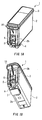
- Figs. 1A and 1B show, merely as an example, a black ink cartridge for an ink-jet printing apparatus.
- an ink cartridge 1 is substantially rectangular parallelepiped.
- the ink cartridge 1 is provided with a housing 2 formed with an ink chamber 60 (shown in Fig. 4) and an opening, and a cover member 3 sealing the opening of the housing 2.
- the ink cartridge 1 further includes an ink supply port 4 formed in one outer wall thereof, i.e., a bottom wall 2a in this embodiment.
- the printing apparatus includes a printhead with nozzles and an ink supply needle which is held in fluid communication with the printhead.
- the ink supply port 4 of the ink cartridge 1 is designed to supply ink to the printhead through the ink supply needle of the printing apparatus when the ink cartridge 1 is mounted on the printing apparatus and the ink supply needle is inserted in the ink supply port 4.
- the bottom wall 2a has substantially square shape formed with two edges of longer width and the other two edges of shorter width.
- the ink supply port 4 is formed at a position closer to one of the shorter edges than the other of the shorter edges.
- the ink cartridge 1 further includes a memory device 6 having a circuit substrate secured to one wall other than the bottom wall 2a.
- the memory device 6 is placed in the vicinity of the ink supply port 4 and preferably, on a side outer wall 2b which is in parallel with the insertion direction of the ink supply needle 52, shown in Fig. 4.
- the memory device 6 is disposed on a center line of the side wall 2b of the housing 2, which wall has a shorter width than the other wall of the housing 2.
- the housing 2 is substantially rectangular in shape, and the side wall 2b of which is substantially perpendicular to the bottom wall 2a on which the ink supply port 4 is formed. Further, the memory device, which has a flat substrate, is disposed substantially in parallel with the side wall 2b.
- the ink supply port 4 of the ink cartridge 1 must be accurately positioned with respect to the ink supply needle of the printing apparatus, more accurate positioning around the ink supply port is accomplished than the other part of the ink cartridge. Accordingly, as the memory device 6 is disposed in the vicinity of the ink supply port 4 according to the present embodiment, an accurate positioning of the memory device 6 with respect to the contact member of the printing apparatus side is necessarily attained. In addition, when the ink cartridge 1 is mounted on the carriage, the level of deviation in position of the ink cartridge 1 with the carriage is less at the center of the ink cartridge than at the side edge parts thereof. Therefore, as the memory device 6 is disposed at the center in the widthwise direction of the sidewall 2b, the level of deviation in position of the memory device 6 is necessarily less.
- the housing 2 is formed with a concave portion in which the memory device 6 is accommodated.
- the ink supply port 4 is initially sealed with a sealing member 7 so that air or bubbles do not enter the ink supply port 4 or ink does not leak out of the ink supply port 4 before use.
- the ink cartridge 1 is formed with a protruding portion 10 which is designed to engage with a hook of a cartridge holder of the printing apparatus for the purpose of aiding mounting and detaching of the ink cartridge 1 on and from the cartridge holder of the printing apparatus. As the protruding portion 10 extends from the side wall 2b on which the memory device 6 is mounted, the positioning accuracy of the memory device with the contact member of the printing apparatus can be attained.
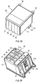
- Figs. 2A and 2B show, as an example, a color ink cartridge 20. Similar to the black ink cartridge 1 shown in Figs. 1A and 1B, the ink cartridge 20 is substantially rectangular parallelepiped.
- the ink cartridge 20 has a housing 21 the interior of which is separated into a plurality of ink chambers by partition walls for accommodating different inks such as different color. According to this embodiment shown in Figs. 2A and 2B, five ink chambers 23 to 27 are defined, and each of the ink chambers 23 to 27 has an opening.
- the ink cartridge further 20 has a cover member 35 sealing all the openings of the ink chambers 23 to 27.
- the ink cartridge 20 includes a plurality of ink supply ports 28 to 32 on one of its sides, each corresponding to the ink chambers 23 to 27.
- Each of the ink supply ports 28 to 32 is held in communication with the respective ink chambers 23 to 27, and is capable of providing ink to a corresponding ink supply needle when the ink supply needle is inserted into each of the ink supply ports 28 to 32.
- the ink supply ports 28 to 32 are formed at positions closer to one edge of a wall the other.
- the ink cartridge 20 is further provided with a memory device 34 secured to one wall other than the wall on which the ink supply ports 28 to 32 are formed.
- the memory device 34 is disposed substantially at a center of the total width of the plurality of ink chambers 23 to 27.
- the memory device 34 is positioned in the vicinity of the ink supply ports 28 to 32 and stores therein, for example, data for specifying the ink cartridge 20.
- the ink supply ports 28 to 32 are initially sealed with a sealing member 35 so that air or bubbles do not enter ink supply ports 28 to 32 or ink does not leak out of the ink supply ports 28 to 32 before use.
- the ink cartridge 20 is formed with a protruding portion 36 which is designed to engage with a hook of the printing apparatus for aiding mounting and detaching of the ink cartridge 20 on the cartridge holder of the printing apparatus.
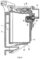
- Figs. 3A and 3B are perspective views of the memory device 6 or 34, showing a first side and a second side, respectively.
- the second side shown in Fig. 3B is attached to the ink cartridge 1 or 20.
- the first side shown in Fig. 3A is seen on the surface.
- the first side is formed with electrodes 42 and 43 which are designed to connect to a contact 40, shown in Fig. 4, of the cartridge holder of the printing apparatus.
- a semiconductor storage device 44 is attached on the second side, i.e., rear side of the memory device 6 or 34.
- the semiconductor storage device 44 can be accessed by the cartridge holder of the printing apparatus via the electrode 42 and 43 of the memory device 6 or 34 and the contact 40, so that information relating to ink or ink cartridge can be stored in or read out from the storage device 44.
- the memory device 6 is provided with a substrate, a plurality of electrode terminals 42, 43 and the semiconductor storage device 44.
- the electrode terminals 42, 43 are arranged on a front surface of the substrate and the storage device 44 is disposed on the other, rear surface of the substrate.
- the semiconductor storage device i.e., the chip
- the semiconductor storage device is disposed on the rear side of the substrate, it is not exposed when the memory device is attached to the ink cartridge 1 and there is no possibility that a user may cause damage even though he drops the ink cartridge 1 on a floor.
- the semiconductor storage device 44 is formed of an electrically rewritable memory such as a nonvolatile memory such as, for example, EEPROM.
- a nonvolatile memory such as, for example, EEPROM.
- the previously written data may be, for example, a serial number for specifying the cartridge 1 or 20, volume of ink contained in the ink cartridge 1 or 20, and data related to a trademark indicating a manufacturer of ink or the ink cartridge 1 or 20.
- the semiconductor storage device 44 is formed to have an area where a volume of ink consumed by a user can be written on.
- Fig. 4 shows a cross sectional view of the black ink cartridge 1 when mounted on a carriage 51 of the printing apparatus.
- the printing apparatus includes a printhead 50 and an ink supply needle 52.
- the ink supply needle 52 forms a sealing connection with the ink supply port 4 of the ink cartridge 1 to be held in communication with the ink chamber 60 via the ink supply port 4.
- the ink supply needle 52 is hollow and formed from a cylindrical body having a tapered portion at its tip end. Therefore, the ink supply needle 52 is easily inserted into and removed from the ink supply port 4. When the ink supply needle 52 is inserted in the ink supply port 4, the ink supply needle 52 forms a sealing connection with a packing member 61 fitted in the ink supply port 4, which will be described hereinbelow.
- Fig. 5 shows an enlarged cross sectional view of the ink supply port 4 and a valve mechanism arranged therein.
- the packing member 61 is press-fitted in the ink supply port 4.
- the packing member 61 defines a hole substantially at a center thereof, allowing the ink supply needle 52 to pass therethrough, shown in Fig. 4.
- the packing member 61 is made of an elastic material such as a rubber material including a silicon rubber, a chloroprene rubber, a butyl rubber, a ethylene-propylene rubber, a nitrile rubber, and an elastomer material.
- a rubber material including a silicon rubber, a chloroprene rubber, a butyl rubber, a ethylene-propylene rubber, a nitrile rubber, and an elastomer material.
- the hole of the packing member 61 has a tapered portion 62 which tapers out to guide the ink supply needle 52 of the printing apparatus, and a cylindrical fitting portion 63 in the vicinity of the ink chamber 60.
- the valve mechanism includes a valve body 65 installed in the ink supply port 4 between the packing member 61 and the ink chamber 60.
- the valve member 65 is always urged vertically with respect to the packing member 61 by a spring 64.
- the valve body 65 and the packing member 61 form a sealing connection.
- the valve body 65 is urged by the ink supply needle 52 against the resilient force of the spring 64 to open the ink supply port 4, when the ink supply needle 52 is inserted in the ink supply port 4.
- the length of the electrode terminals 42 and 43 of the memory device 6 along the direction of insertion of the ink supply needle 52 into the packing member 61 is designed to be longer than the maximum length of entry of the ink supply needle 52 into the ink supply port 4 from the packing member 61, subtracted by a length that the ink supply needle is pushed back by a resilient force of the spring 64 as a reactive force thereof generated by urging the valve body 65.
- the terminal electrodes are arranged on the substrate of the memory device 6 in a position where the electrode terminals start to connect electrically with the contact member 40 of the printing apparatus when the tip end portion of the ink supply needle 52 comes into contact with the valve body 65.
- the length of the electrode terminals along the direction of insertion of the ink supply needle 52 into the packing member is longer than the length that the ink supply needle 52 slides into the housing while pushing the valve body 65 against the resilient force of the spring 64.
- the tip of the ink supply needle 52 penetrates the sealing member 7 sealing the ink supply port 4. Then, the tip of the ink supply needle 52 urges the valve body 65 to open against the resilient force of the spring 64 so that the ink chamber 60 becomes held in communication with the printhead 50.
- the memory device 6 connects to a control unit installed in the printing apparatus, not shown in the drawings, via the contact 40 formed at the cartridge holder 70 in this embodiment.
- the contact 40 has resiliency in the vertical direction with respect to the insertion direction of the ink supply needle 52.
- the memory device 6 is mounted on a side wall which is substantially in parallel with the insertion direction of the ink supply needle 52. Therefore, by forming the electrodes 42 and 43 of the memory device 6 slightly larger than the size necessary to contact with the contact 40, the electrode terminals 42 and 43 of the memory device 6 can ensure the connection with the contact 40 of the carriage 51, regardless of the distance between the ink cartridge 1 and the cartridge holder 70 of the printing apparatus. Furthermore, by forming the electrode terminal 42 relatively longer along the insertion direction of the ink supply needle 52, the electrode terminals 42 and 43 of the memory device 6 can ensure the connection between the contact 40 of the cartridge 1 regardless of the insertion direction of the ink supply needle 52.
- the memory device 6 and the contact 40 are placed such that the contact 40 forms an electric contact with the electrodes 42 and 43 of the memory device 6 only when the ink supply needle 52 is inserted in the ink supply port 4 to open the valve member 65 and ink is supplied from the ink chamber 60 to the printhead 50.
- the fact that data from the storage device 44 can be read out means that the ink cartridge 1 is appropriately mounted on the cartridge holder 70, because the storage device 44 can only be read out when the electric connection between the electrodes 42 and 43 and the contact 40 is formed. Therefore, even if a program for controlling the printing operation of the printing apparatus includes a sequence judging that the ink cartridge 1 is mounted on the cartridge holder 70 by the fact that the data can be read out from the storage device 44, there is no danger that the printing apparatus starts printing operation when ink is not provided to printhead 50. Thus, damage to the printhead 50 can be prevented.
- the printhead 50 can be prevented from sucking air when the ink cartridge 1 is not appropriately mounted on the cartridge holder 70. This fact prevents waste of a large amount of ink for recovering the operation of the printhead 50 that is required when the printhead 50 sucks air or bubbles.
- the ink supply port 4 is formed at a position closer to one of the shorter edges than the other of the bottom wall 2a of the ink cartridge 1 and is retained at a constant position by the ink supply needle 52 provided on the carriage 51 when the ink supply needle 52 is inserted in the ink supply port 4.
- the memory device 6 disposed in the vicinity of the ink supply port 4, which is formed on one wall of the ink cartridge 1, is also retained at a relatively constant position. Therefore, the electric connection between the electrodes 42 and 43 of the memory device 6 and the contact 40 is ensured without changing the position of the memory device 6 even when the carriage 51 traverses and generates shaking.
- the control unit such as a micro computer, not shown in the drawings, counts ejected ink droplets to calculate the amount of consumed ink.
- the control unit writes the amount of consumed ink on the semiconductor storage device 44 of the memory device 6 via the contact 40.
- the printing apparatus prefferably applies a variety of ink cartridges in accordance with different types of printing mediums in order to enable a high print quality or a desired printing condition.
- Fig. 5 which shows a condition where the ink cartridge 1 or 20 is not in use
- the valve body 65 of the ink cartridge 1 or 20 is urged by the spring 64 to close the ink supply port 4. Therefore, even when the ink cartridge 1 or 20 is detached from the carriage 5 for exchange, ink does not leak and undesirable air and bubbles do not enter the ink chamber 60 or 23 to 27.
- the length of the terminal along the direction of insertion of the ink supply needle into the packing member and into said valve seat is longer than the maximum length of entry of the ink supply needle into said ink supply port from said valve seat, subtracted by a length that the ink supply needle is pushed back by a resilient force of said elastic member as a reactive force thereof generated by urging said valve body.
- the semiconductor storage device 44 stores information relating to the amount of the consumed ink, the amount of the ink remaining in the ink chamber 60 or 23 to 27 can be calculated, even when the ink cartridge 1 or 20 is detached once and remounted on the ink carriage 51. Thus, an ink end or near end condition of the ink cartridge 1 can readily be detected.
- Fig. 6 shows another embodiment of an ink cartridge according to the present invention.
- the cartridge 101 includes a porous member 80 and a filter 171 in the ink chamber 60, or 23 to 27.
- the filter 171 is positioned between the ink chamber and the ink supply port 4 and has a flat shape one side of which is in contact with the porous member 80.
- the porous member 80 has a capillary force which is smaller than a negative pressure generated by the nozzles of the printhead 50 but large enough to retain ink therein.
- the filter 171 also has a capillary force which is larger than the capillary force of the porous member 80 and smaller than the negative pressure generated by the printhead 50.
- the filter 171 may be a plate-like member formed of a porous material or a mesh material.
- the pore size or mesh size of the porous member 80 and the filter 171 defines the capillary force thereof. In other words, the capillary force of the porous member 80 and the filter 171 can be controlled by selecting
- a cover member 3 of the ink cartridge 101 is formed with a rib portion including a plurality of protruding portions 72, each of which are spaced apart from each other by a predetermined distance. Owing to these protruding portions 72, a space is defined in the ink chamber 60 between the porous member 80 and the cover member 3 or 22. A part of the ink supply port 4 is formed to protrude inside the ink chamber 60, or 23 to 27. Therefore, the porous member 80 is highly compressed in the vicinity of the ink supply port 4 to reduce the pore size so that the capillary force of the porous member 80 becomes greater in the vicinity of the ink supply port 4 than other parts of the porous member 80.
- the cover member 3 or 22 has an ink injecting hole 73 or 74 and an air hole 75 or 76 which is designed to be open to the external ambient air.
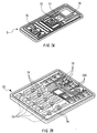
- Fig. 7A is a perspective view showing an upper side of the cover member 3 of the black ink cartridge.
- the cover member 3 has a fine, winding groove 77 connecting the air hole 75 and an air releasing hole 79.
- the air releasing hole 79 is previously sealed by a film before use of the ink cartridge, which will be described in the following, but becomes open to the external ambient air when the film is removed for use.
- Fig. 7B is a perspective view showing an upper side of the cover member 22 of the color ink cartridge.
- the cover member 22 has fine grooves 78 connecting the air hole 76 to air releasing holes 180.
- the air releasing holes 180 are previously sealed by a film before use of the ink cartridge, which will be described in the following, but become open to the external air when the film is removed for use.
- Ink is introduced into the ink chamber of the ink cartridge as will be described in the following.
- the ink supply port 4 is sealed by a film.
- a hollow ink introducing tube is inserted in the ink injecting hole 73 or 74, and a vacuum tube is inserted in the air hole 75 or 76.
- the ink chamber 60 or 23 to 27 is under a low pressure or a vacuum pressure and the ink is introduced from the ink introducing tube under this condition.
- ink can be introduced entirely into the ink chamber 60 or 23 to 27 with little residual air.
- whole of the porous member 80 becomes filled with ink.
- Figs. 8A and 8B show the ink cartridges 1 and 2 with films, respectively.
- the ink cartridge 1 or 20 After introducing the ink into the ink chamber 60 or 23 to 27, the ink cartridge 1 or 20 is placed in a vacuum chamber to further decompress the ink chamber 60 or 23 to 27, if necessary. Then, a film 81 or 82 is attached on the surface of the cover member 3 or 22 to protect the ink chamber 60 or 23 to 27 from ambient air.
- the film 81 or 82 has a tongue part 81a or 82a for easily removing a part of the film 81 or 82 when it is used.
- the ink cartridge 1 or 22 is shipped as a product.
- the ink cartridge may be packaged in a sealed film bag having a high air-impermeability with a decompressed condition, if necessary.
- the ink chamber 60 or 23 to 27 becomes open to the ambient air via a capillary having high fluid resistance formed by the small groove 77 or 78 and the film 81 and 82, respectively.
- the ink cartridge 1 or 22 is mounted on the cartridge holder and the fluid communication with the printhead 50 is accomplished, when printing is started, the negative pressure from the printhead 50 pulls the ink retained by the porous member 80.
- the filter 171 of the ink cartridge 1 or 20 removes air or dust and passes merely ink to the printhead 50.
- the ink does not leak from the ink supply port 4 even when the sealing connection between the valve member 65 and the packing member 61 becomes loose, because the ink is retained by the porous member 80 in the ink chamber 60 or 23 to 27 and blocked by the filter 171 having a high capillary force.
- the ink is retained in the ink chamber 60 or 23 to 27 by the fluid resistance of the capillary action performed by the fine groove 77 or 78 and the film 81 and 82, respectively.
- the packing member 61 may have a slit aperture therein at the ink chamber 60 or 23 to 27 side thereof, which slit can be opened by the insertion of the ink supply needle 52 and can retain the ink by generating a capillary force when the ink supply needle 52 is removed.
- the valve member 65 may not be necessary.
- the structure of the ink cartridge can be further simplified.
- the memory device can accurately store information relating to the amount of the ink remaining in the ink chamber 60 or 23 to 27.
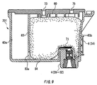
- Fig. 9 is a cross-sectional view showing still another example of an embodiment according to the present invention.
- the ink chamber 60 of an ink cartridge 201 may be separated into an ink chamber 60a and a foam chamber 60b by a partition wall 83 whose bottom portion is formed with a communication hole 83a for communicating the ink chamber 60a with the foam chamber 60b.
- the ink cartridge 201 accommodates a porous member 84 in the foam chamber 60b.
- the filter 171, the ink injecting hole 73, and the air hole 75 are provided in the foam chamber 60b.
- the ink chamber 60a serves as ink storage.
- the ink cartridge thus constructed can perform the same operation as that of the ink cartridge in the embodiments described above.
- porous member 80 or 84 prevents ink from leaking because of its capillary force in the foregoing embodiments
- another ink cartridge which includes only the filter 171, without employing any porous member, can also prevent leakage, to a certain extent, of the ink caused by the weakness of the sealing connection between the valve member 65 and the packing member.
- the ink can be introduced into the ink cartridge 1 or 20 thus constructed by using a refilling unit having the same function as the ink supply needle 52.
- the needle portion of the refilling unit is inserted in the ink supply port 4 to open the valve member 65.
- the semiconductor storage device 44 of the memory device 6 may have an area where the number of times of refill of the ink cartridge 1 or 20 can be written in order to regulate the number of recycling or, in other words, to prevent the cartridge from being recycled to many times. Therefore, the recycled cartridge with a high reliability can be produced.
- an ink cartridge for an ink jet printing apparatus having a printhead which ejects ink droplets onto a recording medium and an ink supply needle introducing ink to the printhead
- the ink cartridge includes: a substantially rectangular housing containing ink therein, said housing having a first outer wall and a second outer wall which is substantially perpendicular to said first outer wall; an ink supply port formed in said first wall for directing ink in said housing to the printhead; a valve mechanism arranged in said ink supply port comprising: a valve seat allowing the ink supply needle to pass therethrough; a valve body movable along the axis of said ink supply port; and an elastic member biasing said valve body against said valve seat, and a memory device for storing information relating to ink mounted on said second wall of said housing and substantially in parallel therewith, said memory device being formed in the vicinity of said ink supply port and said second wall extending in a direction parallel with a direction along which the ink supply needle is inserted into
- Ink is supplied from the ink chamber of the ink cartridge to the printhead of the printing apparatus when the ink supply needle is inserted in the ink supply port of the ink cartridge.
- the memory device is attached on the wall of the ink cartridge which is in parallel with respect to the insertion direction of the ink supply needle, the electric connection between the memory device of the ink cartridge and an external electrode of the printing apparatus can be surely maintained regardless of the variation of the distance between the ink cartridge and the printing apparatus caused by the resilient force of the spring biasing the valve body toward the packing member.
Abstract
Description
- The present invention relates to an ink cartridge detachably attached to a printing apparatus and supplying ink to a printhead of the printing apparatus which ejects ink droplets in accordance with a printing signal.
- Typically, a printhead of an ink-jet printing apparatus connects with an ink cartridge via an ink supply channel. The printhead is designed to receive ink from the ink cartridge. The printing apparatus is provided with a hollow ink supply needle in the ink supply channel to supply ink to the printhead. The ink cartridge is formed with an ink supply port for supplying ink to the printhead. When the ink cartridge is mounted on the printing apparatus, the hollow ink supply needle is inserted into the ink supply port of the ink cartridge and ink is supplied to the printhead via the hollow ink supply needle.
- Unexamined Japanese patent applications (OPI) Nos. Hei. 5-229137 and Hei. 9-174879 disclose an ink cartridge of this structure including a valve member at an upper part of the ink supply port, i.e., inside of the ink cartridge. The ink supply port of the ink cartridge of this type opens when the ink supply needle is inserted, and closes when the ink supply needle is removed. Thus, the ink cartridge is capable of preventing leakage of ink or is capable of being repeatedly attached to the printing apparatus. On the other hand, Unexamined Japanese patent application (OPI) No. Hei. 7-232438 discloses an ink cartridge having a semiconductor memory device that stores data relating to the ink cartridge.
- The conventional valve member as mentioned above, however, has a drawback as the connection between the semiconductor memory device of the ink cartridge and a control unit of the printing apparatus is inadequate. More specifically, as the valve member is always urged by a spring in an insertion direction of the ink supply needle in order to seal the ink supply port, the ink cartridge does not completely fit to a carriage of the printing apparatus because the resilient force of the spring pushes the cartridge up to some extent with respect to the carriage after the ink cartridge is mounted on the carriage. Such results in that the accurate positioning of the ink cartridge with respect to the carriage is hardly accomplished, and if a memory device is mounted on the ink cartridge, the connection of terminals of the memory device to the contact member of a circuit unit of the printing apparatus may be failed due to the deviation caused by the resilient force of the spring urging the valve member.
- Further, if the conventional ink cartridge, which is provided with the valve member, is detached from the carriage of the printing apparatus to exchange to a cartridge of different kind or type while the original ink cartridge is not depleted, the ink may leak out of the ink cartridge through the ink supply port. Such a problem would be more emphasized when the ink cartridge is recycled and the valve or packing becomes worn out and, accordingly, the sealability of the valve mechanism is deteriorated.
- In addition, with respect to the conventional ink cartridge on which the memory device is attached, if the memory device comes into contact the terminal of the printing apparatus whereas the ink supply needle does not correctly enter the ink supply port and thus still not ready for supplying ink, the printing operation may start and air would be conveyed to the nozzles of the printhead. Such could result in a serious problem in giving damage to the printhead, and no recovery can be expected without exchanging the printhead. Therefore, it has been required an appropriate interrelationship of the contact electrode of the memory device with the engagement between the ink supply port and the ink supply needle.
- The present invention was made in view of the foregoing drawbacks accompanying the conventional ink cartridge. Therefore, it is an object of the present invention to provide an ink cartridge capable of performing an adequate connection between a memory device mounted on the ink cartridge and an external circuit unit, regardless of a reactive resilient force of a spring for urging a valve, so that the memory device of the ink cartridge is capable of electrically connecting in a stable manner with the external circuit unit.
- Another object of the present invention is to provide an ink cartridge capable of preventing ink from leaking out through the ink supply port even though the ink cartridge is detached from the printing apparatus for exchanging while ink is not depleted.
- Still another object of the invention is to provide an ink cartridge capable of achieving an appropriate interrelationship of the contact electrode of the memory device with the engagement between the ink supply port and the ink supply needle.
- The above and other objects can be attained by a provision of an ink cartridge for an ink jet printing apparatus having a printhead which ejects ink droplets onto a recording medium and an ink supply needle introducing ink to the printhead which, according to the present invention, includes: a substantially rectangular housing for containing ink therein, said housing having a first outer wall and a second outer wall which is substantially perpendicular to said first outer wall; an ink supply port formed in said first wall for directing ink in said housing to the printhead; a valve mechanism arranged in said ink supply port comprising: a valve seat allowing the ink supply needle to pass therethrough; a valve body movable along the axis of said ink supply port; and an elastic member biasing said valve body against said valve seat, and a memory device for storing information relating to ink mounted on said second wall of said housing and substantially in parallel therewith, said memory device being arranged in the vicinity of said ink supply port, and said second wall extending in a direction parallel with a direction along which the ink supply needle is insertable into said valve seat, said memory device comprising a substrate and a plurality of electrode terminals arranged on one surface of said substrate.
- The memory device may be disposed on a center line of the second wall of the housing. The second wall may have a projection which engages with a hook of an ink cartridge holder of the printing apparatus. The housing may be formed with a concave portion in which the memory device is accommodated. The ink cartridge according to any one of the preceding claims, wherein the housing comprises a plurality of ink chambers for different ink, each chamber comprising an ink supply port, and the memory device is disposed substantially at a center of the total width of the plurality of ink chambers. The memory device comprises a substrate, a plurality of electrode terminals arranged on one surface of the substrate and a storage device disposed on the other surface of the substrate. According to the invention, the memory device may include: a substrate; an electrode terminal arranged on one surface of the substrate at a position where the terminal electrically connects to a contact member of the printing apparatus when the ink supply needle is inserted into the valve seat up to a regular position where the ink supply needle feeds ink; and a storage device secured on the substrate, the storage device communicating with the printing apparatus when the ink cartridge is mounted on the printing apparatus.
- According to the invention, the length of the terminal along the direction of insertion of the ink supply needle into the valve seat is longer than the maximum length of entry of the ink supply needle into the ink supply port from the valve seat, subtracted by a length that the ink supply needle is pushed back by a resilient force of the elastic member as a reactive force thereof generated by urging the valve body. The terminal starts to connect electrically with the contact member of the printing apparatus when the tip end portion of the ink supply needle comes into contact with the valve body. The terminal along the direction of insertion of the ink supply needle into the valve seat is longer than the length that the ink supply needle slides into the housing while pushing the valve body against the elastic member. The housing comprises a cover plate, the cover plate includes: a through-hole; an elongated groove which is in fluid communication with the inside of the housing through the through-hole; and a film covering the top of both the through-hole and the groove so that air flows through the groove and the through-hole into the housing.
- The ink cartridge further includes a cylindrical packing member disposed in the ink supply port for communicating an interior of the housing with the printhead through the ink supply needle, wherein the valve body of the valve mechanism is disposed at the housing side of the cylindrical packing member, and always urged by the elastic member to seal the cylindrical packing member. The ink cartridge may further includes a porous member accommodated in the housing for holding ink. A capillary force of the porous member is greater in the vicinity of the ink supply port than other parts of the porous member.
- According to another aspect of the invention, the above objects can be achieved by a provision of an ink jet printing apparatus which includes: a printhead for ejecting ink droplets onto a recording medium; and an ink container supplying ink contained therein to the printhead, the ink container comprising: a first wall; a second wall; and an ink supply port formed in the first wall for directing ink in the ink container to the printhead; an ink supply needle for feeding ink from the ink container to the printhead by being inserted into the ink supply port; a valve mechanism arranged in the ink supply port comprising: a valve seat allowing the ink supply needle to pass therethrough; a valve body movable along an axis of the ink supply port; and an elastic member biasing the valve body against the valve seat; and a memory device for storing information relating to ink disposed on the second wall of the container, which second wall extends in a direction parallel with a direction along which the ink supply needle is inserted into the ink supply port, the memory device comprising a substrate and a plurality of electrode terminals arranged on one surface of the substrate.
- According to still another aspect of the invention, an ink cartridge for an ink jet printing apparatus includes a cylindrical packing member in an ink supply port thereof for communicating an ink chamber with a printhead through an ink supply needle, characterized in that the ink cartridge comprises a memory device having electrodes for connection, and said electrodes for connection accomplish a conductive relation with external contacts under a condition where the ink supply needle assuredly engages with the cylindrical packing member to allow ink to be supplied.
- According to still another object of the invention, the above objects can be achieved by a provision of an ink cartridge communicating an ink chamber with a printhead through an ink supply needle and comprising a re-seal structure arranged in an ink supply port thereof, which is characterized in that the ink cartridge comprises a memory device for storing thereon information relating to the ink cartridge and a porous member for holding ink arranged at the ink chamber side of the re-seal member.
- The ink chamber communicates with ambient air through a capillary action formed in a surface of the cartridge body. The re-seal structure is capable of supplying ink to the printhead in response to a negative pressure applied from the printhead, a porous member for holding ink is disposed, and a packing member is formed at the ink chamber side with a slit which is openable by the insertion of the ink supply needle.
- According to still another object of the invention, the above objects can be attained by a provision of an ink cartridge for an ink jet printing apparatus which comprises a cylindrical packing in an ink supply port thereof for communicating an ink chamber with a printhead through an ink supply needle, characterized in that a valve body is disposed at an ink chamber side of the cylindrical packing, and always urged by a spring to seal the cylindrical packing, and a memory means, having electrodes for connection, is disposed on a wall of the ink cartridge, which wall being in parallel with an insertion direction of the ink supply needle.
- The memory means is disposed on a wall which is in the vicinity of the ink supply port. The memory means has a region on which data of ink consumption amount is stored. The memory means has a region on which a recycling information of the ink cartridge is stored. The memory means may have one surface forming a front surface on which the electrodes for external connection are formed and a rear surface on which a semiconductor storage means is installed. Further, a porous member is housed in the ink chamber at least in the vicinity of the valve body. A porous member is housed in the ink chamber and a filter is provided upstream of the valve body. In addition, a cover plate for sealing an upper part of the ink chamber is formed with an air hole which communicates with ambient air through fine grooves formed in the surface of the cover plate.
-
- Fig. 1A shows a perspective view of a black ink cartridge according to the present invention viewed from above, and Fig. 1B shows a perspective view of the black ink cartridge according to the present invention viewed from below;
- Fig. 2A shows a perspective view of a color ink cartridge according to the present invention viewed from above, and Fig. 2B shows a perspective view of the color ink cartridge according to the present invention viewed from below;
- Fig. 3A shows a perspective view of the circuit substrate showing the first side, and Fig. 3B shows a perspective view of the circuit substrate showing the second side;
- Fig. 4 shows a cross sectional view of the black ink cartridge when mounted on a carriage of the printing apparatus;
- Fig. 5 shows an enlarged cross sectional view of the ink supply port;
- Fig. 6 shows another embodiment of a cartridge according to the present invention;
- Fig. 7A shows upper side of the cover member of the black
ink cartridge, and Fig. 7B shows upper side of the
cover member 22 of the color ink cartridge; - Fig. 8A shows the black ink cartridge with a film, and Fig. 8B shows the color ink cartridge with a film; and
- Fig. 9 shows another embodiment of the valve member.
-
- The present invention will now be described in detail with reference to accompanying drawings. This does not intend to limit the scope of the present invention, but exemplify the invention. All of the features and the combinations thereof described in the embodiment are not necessarily essential to the invention.
- Figs. 1A and 1B show, merely as an example, a black ink cartridge for an ink-jet printing apparatus. As shown in the figures, an ink cartridge 1 is substantially rectangular parallelepiped. The ink cartridge 1 is provided with a
housing 2 formed with an ink chamber 60 (shown in Fig. 4) and an opening, and acover member 3 sealing the opening of thehousing 2. The ink cartridge 1 further includes anink supply port 4 formed in one outer wall thereof, i.e., abottom wall 2a in this embodiment. The printing apparatus includes a printhead with nozzles and an ink supply needle which is held in fluid communication with the printhead. Theink supply port 4 of the ink cartridge 1 is designed to supply ink to the printhead through the ink supply needle of the printing apparatus when the ink cartridge 1 is mounted on the printing apparatus and the ink supply needle is inserted in theink supply port 4. Thebottom wall 2a has substantially square shape formed with two edges of longer width and the other two edges of shorter width. Theink supply port 4 is formed at a position closer to one of the shorter edges than the other of the shorter edges. - The ink cartridge 1 further includes a
memory device 6 having a circuit substrate secured to one wall other than thebottom wall 2a. Thememory device 6 is placed in the vicinity of theink supply port 4 and preferably, on a sideouter wall 2b which is in parallel with the insertion direction of theink supply needle 52, shown in Fig. 4. As shown in Figs. 1A and 1B, thememory device 6 is disposed on a center line of theside wall 2b of thehousing 2, which wall has a shorter width than the other wall of thehousing 2. Thehousing 2 is substantially rectangular in shape, and theside wall 2b of which is substantially perpendicular to thebottom wall 2a on which theink supply port 4 is formed. Further, the memory device, which has a flat substrate, is disposed substantially in parallel with theside wall 2b. - Because the
ink supply port 4 of the ink cartridge 1 must be accurately positioned with respect to the ink supply needle of the printing apparatus, more accurate positioning around the ink supply port is accomplished than the other part of the ink cartridge. Accordingly, as thememory device 6 is disposed in the vicinity of theink supply port 4 according to the present embodiment, an accurate positioning of thememory device 6 with respect to the contact member of the printing apparatus side is necessarily attained. In addition, when the ink cartridge 1 is mounted on the carriage, the level of deviation in position of the ink cartridge 1 with the carriage is less at the center of the ink cartridge than at the side edge parts thereof. Therefore, as thememory device 6 is disposed at the center in the widthwise direction of thesidewall 2b, the level of deviation in position of thememory device 6 is necessarily less. - According to the present embodiment, the
housing 2 is formed with a concave portion in which thememory device 6 is accommodated. - The
ink supply port 4 is initially sealed with a sealing member 7 so that air or bubbles do not enter theink supply port 4 or ink does not leak out of theink supply port 4 before use. The ink cartridge 1 is formed with a protrudingportion 10 which is designed to engage with a hook of a cartridge holder of the printing apparatus for the purpose of aiding mounting and detaching of the ink cartridge 1 on and from the cartridge holder of the printing apparatus. As the protrudingportion 10 extends from theside wall 2b on which thememory device 6 is mounted, the positioning accuracy of the memory device with the contact member of the printing apparatus can be attained. - Figs. 2A and 2B show, as an example, a
color ink cartridge 20. Similar to the black ink cartridge 1 shown in Figs. 1A and 1B, theink cartridge 20 is substantially rectangular parallelepiped. Theink cartridge 20 has ahousing 21 the interior of which is separated into a plurality of ink chambers by partition walls for accommodating different inks such as different color. According to this embodiment shown in Figs. 2A and 2B, fiveink chambers 23 to 27 are defined, and each of theink chambers 23 to 27 has an opening. The ink cartridge further 20 has acover member 35 sealing all the openings of theink chambers 23 to 27. Theink cartridge 20 includes a plurality ofink supply ports 28 to 32 on one of its sides, each corresponding to theink chambers 23 to 27. Each of theink supply ports 28 to 32 is held in communication with therespective ink chambers 23 to 27, and is capable of providing ink to a corresponding ink supply needle when the ink supply needle is inserted into each of theink supply ports 28 to 32. As illustrated in Fig. 2B, theink supply ports 28 to 32 are formed at positions closer to one edge of a wall the other. - The
ink cartridge 20 is further provided with amemory device 34 secured to one wall other than the wall on which theink supply ports 28 to 32 are formed. According to the present embodiment, as shown in Fig. 2B, thememory device 34 is disposed substantially at a center of the total width of the plurality ofink chambers 23 to 27. Thememory device 34 is positioned in the vicinity of theink supply ports 28 to 32 and stores therein, for example, data for specifying theink cartridge 20. - The
ink supply ports 28 to 32 are initially sealed with a sealingmember 35 so that air or bubbles do not enterink supply ports 28 to 32 or ink does not leak out of theink supply ports 28 to 32 before use. Theink cartridge 20 is formed with a protrudingportion 36 which is designed to engage with a hook of the printing apparatus for aiding mounting and detaching of theink cartridge 20 on the cartridge holder of the printing apparatus. - Figs. 3A and 3B are perspective views of the
memory device memory device ink cartridge 1 or 20, respectively, the second side shown in Fig. 3B is attached to theink cartridge 1 or 20. Thus, the first side shown in Fig. 3A is seen on the surface. The first side is formed withelectrodes contact 40, shown in Fig. 4, of the cartridge holder of the printing apparatus. Asemiconductor storage device 44 is attached on the second side, i.e., rear side of thememory device semiconductor storage device 44 can be accessed by the cartridge holder of the printing apparatus via theelectrode memory device contact 40, so that information relating to ink or ink cartridge can be stored in or read out from thestorage device 44. Thememory device 6 is provided with a substrate, a plurality ofelectrode terminals semiconductor storage device 44. Theelectrode terminals storage device 44 is disposed on the other, rear surface of the substrate. Because the semiconductor storage device, i.e., the chip, is disposed on the rear side of the substrate, it is not exposed when the memory device is attached to the ink cartridge 1 and there is no possibility that a user may cause damage even though he drops the ink cartridge 1 on a floor. - The
semiconductor storage device 44 is formed of an electrically rewritable memory such as a nonvolatile memory such as, for example, EEPROM. When theink cartridge 1 or 20 is shipped from a manufacturing factory, data related to ink or to theink cartridge 1 or 20 is previously written on thesemiconductor storage device 44. The previously written data may be, for example, a serial number for specifying thecartridge 1 or 20, volume of ink contained in theink cartridge 1 or 20, and data related to a trademark indicating a manufacturer of ink or theink cartridge 1 or 20. Thesemiconductor storage device 44 is formed to have an area where a volume of ink consumed by a user can be written on. - Fig. 4 shows a cross sectional view of the black ink cartridge 1 when mounted on a
carriage 51 of the printing apparatus. The printing apparatus includes aprinthead 50 and anink supply needle 52. When the ink cartridge 1 is mounted on a predetermined position of thecarriage 51 on which theprinthead 50 is secured, theink supply needle 52 forms a sealing connection with theink supply port 4 of the ink cartridge 1 to be held in communication with theink chamber 60 via theink supply port 4. - The
ink supply needle 52 is hollow and formed from a cylindrical body having a tapered portion at its tip end. Therefore, theink supply needle 52 is easily inserted into and removed from theink supply port 4. When theink supply needle 52 is inserted in theink supply port 4, theink supply needle 52 forms a sealing connection with a packingmember 61 fitted in theink supply port 4, which will be described hereinbelow. - Fig. 5 shows an enlarged cross sectional view of the
ink supply port 4 and a valve mechanism arranged therein. The packingmember 61 is press-fitted in theink supply port 4. The packingmember 61 defines a hole substantially at a center thereof, allowing theink supply needle 52 to pass therethrough, shown in Fig. 4. - The packing
member 61 is made of an elastic material such as a rubber material including a silicon rubber, a chloroprene rubber, a butyl rubber, a ethylene-propylene rubber, a nitrile rubber, and an elastomer material. - The hole of the packing
member 61 has a taperedportion 62 which tapers out to guide theink supply needle 52 of the printing apparatus, and a cylindricalfitting portion 63 in the vicinity of theink chamber 60. The valve mechanism includes avalve body 65 installed in theink supply port 4 between the packingmember 61 and theink chamber 60. Thevalve member 65 is always urged vertically with respect to the packingmember 61 by aspring 64. Thus, thevalve body 65 and the packingmember 61 form a sealing connection. Thevalve body 65 is urged by theink supply needle 52 against the resilient force of thespring 64 to open theink supply port 4, when theink supply needle 52 is inserted in theink supply port 4. - The length of the
electrode terminals memory device 6 along the direction of insertion of theink supply needle 52 into the packingmember 61 is designed to be longer than the maximum length of entry of theink supply needle 52 into theink supply port 4 from the packingmember 61, subtracted by a length that the ink supply needle is pushed back by a resilient force of thespring 64 as a reactive force thereof generated by urging thevalve body 65. The terminal electrodes are arranged on the substrate of thememory device 6 in a position where the electrode terminals start to connect electrically with thecontact member 40 of the printing apparatus when the tip end portion of theink supply needle 52 comes into contact with thevalve body 65. In addition, the length of the electrode terminals along the direction of insertion of theink supply needle 52 into the packing member is longer than the length that theink supply needle 52 slides into the housing while pushing thevalve body 65 against the resilient force of thespring 64. - Referring back to Fig. 4, when the ink cartridge 1 is mounted on the
cartridge holder 70 and alever 71 is pushed down, the tip of theink supply needle 52 penetrates the sealing member 7 sealing theink supply port 4. Then, the tip of theink supply needle 52 urges thevalve body 65 to open against the resilient force of thespring 64 so that theink chamber 60 becomes held in communication with theprinthead 50. Thememory device 6 connects to a control unit installed in the printing apparatus, not shown in the drawings, via thecontact 40 formed at thecartridge holder 70 in this embodiment. Thecontact 40 has resiliency in the vertical direction with respect to the insertion direction of theink supply needle 52. - The
memory device 6 according to the present embodiment is mounted on a side wall which is substantially in parallel with the insertion direction of theink supply needle 52. Therefore, by forming theelectrodes memory device 6 slightly larger than the size necessary to contact with thecontact 40, theelectrode terminals memory device 6 can ensure the connection with thecontact 40 of thecarriage 51, regardless of the distance between the ink cartridge 1 and thecartridge holder 70 of the printing apparatus. Furthermore, by forming theelectrode terminal 42 relatively longer along the insertion direction of theink supply needle 52, theelectrode terminals memory device 6 can ensure the connection between thecontact 40 of the cartridge 1 regardless of the insertion direction of theink supply needle 52. It is desirable that thememory device 6 and thecontact 40 are placed such that thecontact 40 forms an electric contact with theelectrodes memory device 6 only when theink supply needle 52 is inserted in theink supply port 4 to open thevalve member 65 and ink is supplied from theink chamber 60 to theprinthead 50. - With the afore-described structure, the fact that data from the
storage device 44 can be read out means that the ink cartridge 1 is appropriately mounted on thecartridge holder 70, because thestorage device 44 can only be read out when the electric connection between theelectrodes contact 40 is formed. Therefore, even if a program for controlling the printing operation of the printing apparatus includes a sequence judging that the ink cartridge 1 is mounted on thecartridge holder 70 by the fact that the data can be read out from thestorage device 44, there is no danger that the printing apparatus starts printing operation when ink is not provided toprinthead 50. Thus, damage to theprinthead 50 can be prevented. - With this structure, the
printhead 50 can be prevented from sucking air when the ink cartridge 1 is not appropriately mounted on thecartridge holder 70. This fact prevents waste of a large amount of ink for recovering the operation of theprinthead 50 that is required when theprinthead 50 sucks air or bubbles. - Furthermore, the
ink supply port 4 is formed at a position closer to one of the shorter edges than the other of thebottom wall 2a of the ink cartridge 1 and is retained at a constant position by theink supply needle 52 provided on thecarriage 51 when theink supply needle 52 is inserted in theink supply port 4. Thus, thememory device 6 disposed in the vicinity of theink supply port 4, which is formed on one wall of the ink cartridge 1, is also retained at a relatively constant position. Therefore, the electric connection between theelectrodes memory device 6 and thecontact 40 is ensured without changing the position of thememory device 6 even when thecarriage 51 traverses and generates shaking. - When the printing operation is started and ink is consumed by the
printhead 50, that is, whenprinthead 50 ejects ink droplets, under this condition, the control unit such as a micro computer, not shown in the drawings, counts ejected ink droplets to calculate the amount of consumed ink. The control unit writes the amount of consumed ink on thesemiconductor storage device 44 of thememory device 6 via thecontact 40. - It is preferable for the printing apparatus to apply a variety of ink cartridges in accordance with different types of printing mediums in order to enable a high print quality or a desired printing condition.
- As shown in Fig. 5, which shows a condition where the
ink cartridge 1 or 20 is not in use, thevalve body 65 of theink cartridge 1 or 20 is urged by thespring 64 to close theink supply port 4. Therefore, even when theink cartridge 1 or 20 is detached from thecarriage 5 for exchange, ink does not leak and undesirable air and bubbles do not enter theink chamber - The length of the terminal along the direction of insertion of the ink supply needle into the packing member and into said valve seat is longer than the maximum length of entry of the ink supply needle into said ink supply port from said valve seat, subtracted by a length that the ink supply needle is pushed back by a resilient force of said elastic member as a reactive force thereof generated by urging said valve body.
- As the
semiconductor storage device 44 stores information relating to the amount of the consumed ink, the amount of the ink remaining in theink chamber ink cartridge 1 or 20 is detached once and remounted on theink carriage 51. Thus, an ink end or near end condition of the ink cartridge 1 can readily be detected. - Fig. 6 shows another embodiment of an ink cartridge according to the present invention. The
cartridge 101 includes aporous member 80 and afilter 171 in theink chamber filter 171 is positioned between the ink chamber and theink supply port 4 and has a flat shape one side of which is in contact with theporous member 80. Theporous member 80 has a capillary force which is smaller than a negative pressure generated by the nozzles of theprinthead 50 but large enough to retain ink therein. Thefilter 171 also has a capillary force which is larger than the capillary force of theporous member 80 and smaller than the negative pressure generated by theprinthead 50. Thefilter 171 may be a plate-like member formed of a porous material or a mesh material. The pore size or mesh size of theporous member 80 and thefilter 171 defines the capillary force thereof. In other words, the capillary force of theporous member 80 and thefilter 171 can be controlled by selecting an appropriate pore size or mesh size. - A
cover member 3 of theink cartridge 101 is formed with a rib portion including a plurality of protrudingportions 72, each of which are spaced apart from each other by a predetermined distance. Owing to these protrudingportions 72, a space is defined in theink chamber 60 between theporous member 80 and thecover member ink supply port 4 is formed to protrude inside theink chamber porous member 80 is highly compressed in the vicinity of theink supply port 4 to reduce the pore size so that the capillary force of theporous member 80 becomes greater in the vicinity of theink supply port 4 than other parts of theporous member 80. - The
cover member ink injecting hole air hole - Fig. 7A is a perspective view showing an upper side of the
cover member 3 of the black ink cartridge. Thecover member 3 has a fine, windinggroove 77 connecting theair hole 75 and anair releasing hole 79. Theair releasing hole 79 is previously sealed by a film before use of the ink cartridge, which will be described in the following, but becomes open to the external ambient air when the film is removed for use. - Fig. 7B is a perspective view showing an upper side of the
cover member 22 of the color ink cartridge. Thecover member 22 hasfine grooves 78 connecting theair hole 76 to air releasingholes 180. Theair releasing holes 180 are previously sealed by a film before use of the ink cartridge, which will be described in the following, but become open to the external air when the film is removed for use. - Ink is introduced into the ink chamber of the ink cartridge as will be described in the following. First, the
ink supply port 4 is sealed by a film. Then, a hollow ink introducing tube, not shown in the drawings, is inserted in theink injecting hole air hole ink chamber - As the
ink chamber ink supply port 4 or theporous member 80, ink can be introduced entirely into theink chamber porous member 80 becomes filled with ink. - Figs. 8A and 8B show the
ink cartridges 1 and 2 with films, respectively. - After introducing the ink into the
ink chamber ink cartridge 1 or 20 is placed in a vacuum chamber to further decompress theink chamber film cover member ink chamber film tongue part film ink cartridge 1 or 22 is shipped as a product. The ink cartridge may be packaged in a sealed film bag having a high air-impermeability with a decompressed condition, if necessary. - Before using the
ink cartridge 1 or 21 thus constructed, a part of thefilm tongue part air releasing hole ink chamber small groove film - After the
ink cartridge 1 or 22 is mounted on the cartridge holder and the fluid communication with theprinthead 50 is accomplished, when printing is started, the negative pressure from theprinthead 50 pulls the ink retained by theporous member 80. Thefilter 171 of theink cartridge 1 or 20 removes air or dust and passes merely ink to theprinthead 50. - As shown in Fig. 5, since the
valve member 65 of theink cartridge 1 or 20 is always urged by the resilient force of thespring 64, theink supply port 4 is closed by the valve mechanism at a time when theink supply needle 52 comes out of contact with the packingmember 61. Therefore, even when theink cartridge 1 or 20 is detached from thecarriage 5 for changing to a different type of ink for printing, ink does not leak from theink chamber 60, and undesirable air and bubbles do not enter theink supply port 4. - Furthermore, in the preferred embodiment, the ink does not leak from the
ink supply port 4 even when the sealing connection between thevalve member 65 and the packingmember 61 becomes loose, because the ink is retained by theporous member 80 in theink chamber filter 171 having a high capillary force. The ink is retained in theink chamber fine groove film - In one arrangement of the embodiment, the packing
member 61 may have a slit aperture therein at theink chamber ink supply needle 52 and can retain the ink by generating a capillary force when theink supply needle 52 is removed. In such arrangement, thevalve member 65 may not be necessary. Thus, the structure of the ink cartridge can be further simplified. - As the
ink chamber fine groove film ink chamber - Fig. 9 is a cross-sectional view showing still another example of an embodiment according to the present invention. In the present embodiment, the
ink chamber 60 of anink cartridge 201 may be separated into anink chamber 60a and afoam chamber 60b by apartition wall 83 whose bottom portion is formed with acommunication hole 83a for communicating theink chamber 60a with thefoam chamber 60b. - The
ink cartridge 201 accommodates aporous member 84 in thefoam chamber 60b. Thefilter 171, theink injecting hole 73, and theair hole 75 are provided in thefoam chamber 60b. Theink chamber 60a serves as ink storage. The ink cartridge thus constructed can perform the same operation as that of the ink cartridge in the embodiments described above. - Furthermore, although the
porous member filter 171, without employing any porous member, can also prevent leakage, to a certain extent, of the ink caused by the weakness of the sealing connection between thevalve member 65 and the packing member. - The ink can be introduced into the
ink cartridge 1 or 20 thus constructed by using a refilling unit having the same function as theink supply needle 52. The needle portion of the refilling unit is inserted in theink supply port 4 to open thevalve member 65. Thus, the ink cartridge is recycled. Thesemiconductor storage device 44 of thememory device 6 may have an area where the number of times of refill of theink cartridge 1 or 20 can be written in order to regulate the number of recycling or, in other words, to prevent the cartridge from being recycled to many times. Therefore, the recycled cartridge with a high reliability can be produced. - As described above, an ink cartridge for an ink jet printing apparatus according to the present invention having a printhead which ejects ink droplets onto a recording medium and an ink supply needle introducing ink to the printhead, the ink cartridge includes: a substantially rectangular housing containing ink therein, said housing having a first outer wall and a second outer wall which is substantially perpendicular to said first outer wall; an ink supply port formed in said first wall for directing ink in said housing to the printhead; a valve mechanism arranged in said ink supply port comprising: a valve seat allowing the ink supply needle to pass therethrough; a valve body movable along the axis of said ink supply port; and an elastic member biasing said valve body against said valve seat, and a memory device for storing information relating to ink mounted on said second wall of said housing and substantially in parallel therewith, said memory device being formed in the vicinity of said ink supply port and said second wall extending in a direction parallel with a direction along which the ink supply needle is inserted into said valve seat.
- Ink is supplied from the ink chamber of the ink cartridge to the printhead of the printing apparatus when the ink supply needle is inserted in the ink supply port of the ink cartridge. As the memory device is attached on the wall of the ink cartridge which is in parallel with respect to the insertion direction of the ink supply needle, the electric connection between the memory device of the ink cartridge and an external electrode of the printing apparatus can be surely maintained regardless of the variation of the distance between the ink cartridge and the printing apparatus caused by the resilient force of the spring biasing the valve body toward the packing member.
Claims (27)
- An ink cartridge for an ink jet printing apparatus having a printhead which ejects ink droplets onto a recording medium and an ink supply needle for introducing ink to the printhead, the ink cartridge comprising:a substantially rectangular housing for containing ink therein, said housing having a first outer wall and a second outer wall which is substantially perpendicular to said first outer wall;an ink supply port formed in said first wall for directing ink in said housing to the printhead;a valve mechanism arranged in said ink supply port comprising:a valve seat allowing the ink supply needle to pass therethrough;a valve body movable along the axis of said ink supply port; andan elastic member biasing said valve body against said valve seat, anda memory device for storing information relating to ink mounted on said second wall of said housing and substantially in parallel therewith, said memory device being arranged in the vicinity of said ink supply port, and said second wall extending in a direction parallel with a direction along which the ink supply needle is insertable into said valve seat, said memory device comprising a substrate and a plurality of electrode terminals arranged on one surface of said substrate.
- The ink cartridge according to claim 1, wherein said memory device is disposed on a center line of said second wall of said housing.
- The ink cartridge according to claim 1 or 2, wherein said second wall has a projection which engages with a hook of an ink cartridge holder of the printing apparatus.
- The ink cartridge according to any one of the preceding claims, wherein said housing is formed with a concave portion in which said memory device is accommodated.
- The ink cartridge according to any one of the preceding claims, wherein said housing comprises a plurality of ink chambers for different ink, each chamber comprising an ink supply port, and said memory device is disposed substantially at a center of the total width of said plurality of ink chambers.
- The ink cartridge according to any one of the preceding claims, wherein said memory device comprises a substrate, a plurality of electrode terminals arranged on one surface of said substrate and a storage device disposed on the other surface of said substrate.
- The ink cartridge according to any one of the preceding claims 1 to 6, wherein said memory device comprising:a substrate;an electrode terminal arranged on one surface of said substrate at a position where said terminal electrically connects to a contact member of the printing apparatus when the ink supply needle is inserted into said valve seat up to a regular position where the ink supply needle feeds ink; anda storage device secured on said substrate, said storage device communicating with the printing apparatus when the ink cartridge is mounted on the printing apparatus.
- The ink cartridge according to claim 7, wherein the length of said terminal along the direction of insertion of the ink supply needle into said valve seat is longer than the maximum length of entry of the ink supply needle into said ink supply port from said valve seat, subtracted by a length that the ink supply needle is pushed back by a resilient force of said elastic member as a reactive force thereof generated by urging said valve body.
- The ink cartridge according to claim 7 or 8, said terminal being arranged on said substrate in a position where said terminal starts to connect electrically with the contact member of the printing apparatus when the tip end portion of the ink supply needle comes into contact with said valve body.
- The ink cartridge according to claim 9, wherein the length of said terminal along the direction of insertion of the ink supply needle into said valve seat is longer than the length that the ink supply needle slides into said housing while pushing said valve body against said elastic member.
- The ink cartridge according to any one of the preceding claims, wherein said housing comprises a cover plate, said cover plate comprising:a through-hole;an elongated groove which is in fluid communication with the inside of said housing through said through-hole; anda film covering the top of both said through-hole and said groove so that air flows through said groove and said through-hole into said housing.
- The ink cartridge according to claim 1, further comprising a cylindrical packing member disposed in said ink supply port for communicating an interior of said housing with the printhead through the ink supply needle, wherein said valve body of said valve mechanism is disposed at the housing side of said cylindrical packing member, and always urged by said elastic member to seal said cylindrical packing member.
- The ink cartridge according to any one of the preceding claims, further comprising a porous member accommodated in said housing for holding ink.
- The ink cartridge according to claim 13, wherein a capillary force of said porous member is greater in the vicinity of said ink supply port than other parts of said porous member.
- An ink jet printing apparatus, comprising:a printhead for ejecting ink droplets onto a recording medium; andan ink container supplying ink contained therein to said printhead, said ink container comprising:a first wall;a second wall; andan ink supply port formed in said first wall for directing ink in said ink container to said printhead;an ink supply needle for feeding ink from said ink container to said printhead by being inserted into said ink supply port;a valve mechanism arranged in said ink supply port comprising:a valve seat allowing said ink supply needle to pass therethrough;a valve body movable along an axis of said ink supply port; andan elastic member biasing said valve body against said valve seat; anda memory device for storing information relating to ink disposed on said second wall of said container, which second wall extends in a direction parallel with a direction along which said ink supply needle is inserted into said ink supply port, said memory device comprising a substrate and a plurality of electrode terminals arranged on one surface of said substrate.
- An ink cartridge for an ink jet printing apparatus comprising a cylindrical packing member in an ink supply port thereof for communicating an ink chamber with a printhead through an ink supply needle, characterized in that the ink cartridge comprises a memory device having electrodes for connection, and said electrodes for connection accomplish a conductive relation with external contacts under a condition where the ink supply needle assuredly engages with said cylindrical packing member to allow ink to be supplied.
- An ink cartridge communicating an ink chamber with a printhead through an ink supply needle and comprising a re-seal structure arranged in an ink supply port thereof, characterized in that the ink cartridge comprises a memory device for storing thereon information relating to the ink cartridge and a porous member for holding ink arranged at the ink chamber side of the re-seal member.
- The ink cartridge according to claim 17, wherein the ink chamber communicates with ambient air through a capillary action formed in a surface of the cartridge body.
- The ink cartridge according to claim 17, wherein said re-seal structure is capable of supplying ink to the printhead in response to a negative pressure applied from the printhead, a porous member for holding ink is disposed, and a packing member is formed at the ink chamber side with a slit which is openable by the insertion of the ink supply needle.
- An ink cartridge for an ink jet printing apparatus comprising a cylindrical packing in an ink supply port thereof for communicating an ink chamber with a printhead through an ink supply needle, characterized in that a valve body is disposed at an ink chamber side of the cylindrical packing, and always urged by a spring to seal the cylindrical packing, and a memory means, having electrodes for connection, is disposed on a wall of the ink cartridge, which wall being in parallel with an insertion direction of the ink supply needle.
- The ink cartridge according to claim 20, wherein said memory means is disposed on a wall which is in the vicinity of the ink supply port.
- The ink cartridge according to claim 20 or 21, wherein said memory means has a region on which data of ink consumption amount is stored.
- The ink cartridge according to claim 20, 21 or 22, wherein the memory means has a region on which a recycling information of the ink cartridge is stored.
- The ink cartridge according to any one of the preceding claims 20 to 23, wherein said memory means has one surface forming a front surface on which the electrodes for external connection are formed and a rear surface on which a semiconductor storage means is installed.
- The ink cartridge according to any one of the preceding claims 20 to 24, wherein a porous member is housed in said ink chamber at least in the vicinity of said valve body.
- The ink cartridge according to any one of the preceding claims 20 to 24, wherein a porous member is housed in said ink chamber and a filter is provided upstream of said valve body.
- The ink cartridge according to any one of the preceding claims 20 to 26, wherein a cover plate for sealing an upper part of said ink chamber is formed with an air hole which communicates with ambient air through fine grooves formed in the surface of the cover plate.
Applications Claiming Priority (2)
| Application Number | Priority Date | Filing Date | Title |
|---|---|---|---|
| JP29018999 | 1999-10-12 | ||
| JP29018999 | 1999-10-12 |
Publications (3)
| Publication Number | Publication Date |
|---|---|
| EP1092546A2 true EP1092546A2 (en) | 2001-04-18 |
| EP1092546A3 EP1092546A3 (en) | 2002-01-23 |
| EP1092546B1 EP1092546B1 (en) | 2009-06-24 |
Family
ID=17752913
Family Applications (1)
| Application Number | Title | Priority Date | Filing Date |
|---|---|---|---|
| EP00121388A Revoked EP1092546B1 (en) | 1999-10-12 | 2000-10-12 | Ink cartridge for ink-jet printing apparatus |
Country Status (13)
| Country | Link |
|---|---|
| US (2) | US6634738B1 (en) |
| EP (1) | EP1092546B1 (en) |
| KR (1) | KR100373553B1 (en) |
| CN (3) | CN1278862C (en) |
| AT (1) | ATE434524T1 (en) |
| CA (1) | CA2322902C (en) |
| DE (1) | DE60042441D1 (en) |
| ES (1) | ES2325762T3 (en) |
| HK (1) | HK1034494A1 (en) |
| ID (1) | ID27470A (en) |
| MY (2) | MY140763A (en) |
| SG (2) | SG113460A1 (en) |
| TW (2) | TWI245708B (en) |
Cited By (10)
| Publication number | Priority date | Publication date | Assignee | Title |
|---|---|---|---|---|
| EP1281897A1 (en) * | 2001-07-30 | 2003-02-05 | Hewlett-Packard Company | Elastomeric valve |
| EP1297962A1 (en) * | 2001-09-28 | 2003-04-02 | Canon Kabushiki Kaisha | Liquid container and ink jet recording apparatus employing liquid container |
| WO2003037634A1 (en) * | 2001-10-31 | 2003-05-08 | Print-Rite Unicorn Image Products Co. Ltd Of Zhuhai | An ink cartridge for a printer |
| WO2003103973A1 (en) * | 2002-06-11 | 2003-12-18 | セイコーエプソン株式会社 | Ink cartridge |
| EP1382450A1 (en) * | 2002-07-18 | 2004-01-21 | Eastman Kodak Company | Ink cartridge having shielded pocket for memory chip |
| EP1364795A3 (en) * | 2002-05-16 | 2004-07-07 | Samsung Electronics Co., Ltd. | Ink cartridge |
| EP1439067A1 (en) * | 2003-01-15 | 2004-07-21 | Pelikan Hardcopy Production AG | Method for inserting a support in a cartridge holding device and corresponding support |
| EP1454752A1 (en) * | 2003-02-14 | 2004-09-08 | Riso Kagaku Corporation | Ink container |
| WO2007008998A2 (en) * | 2005-07-13 | 2007-01-18 | Fujifilm Dimatix, Inc. | Fluid deposition device |
| SG154325A1 (en) * | 2002-03-29 | 2009-08-28 | Seiko Epson Corp | A printing apparatus and ink cartridge therefor |
Families Citing this family (54)
| Publication number | Priority date | Publication date | Assignee | Title |
|---|---|---|---|---|
| EP2179848A1 (en) * | 1998-05-18 | 2010-04-28 | Seiko Epson Corporation | Ink-jet printing apparatus and ink cartridge therefor |
| CN1278862C (en) * | 1999-10-12 | 2006-10-11 | 精工爱普生株式会社 | Ink box for ink-jet printer |
| CA2379725C (en) * | 2001-04-03 | 2007-06-12 | Seiko Epson Corporation | Ink cartridge |
| CN100460212C (en) * | 2002-03-29 | 2009-02-11 | 精工爱普生株式会社 | Printing apparatus and ink cartridge therefor |
| JP4194298B2 (en) * | 2002-05-17 | 2008-12-10 | キヤノン株式会社 | Information storage medium, unit, process cartridge, developing cartridge, and electrophotographic image forming apparatus |
| US7702419B2 (en) * | 2002-07-16 | 2010-04-20 | Hewlett-Packard Development Company, L.P. | System and method for filling a reservoir |
| JP3809828B2 (en) * | 2002-12-10 | 2006-08-16 | セイコーエプソン株式会社 | Method for manufacturing liquid cartridge |
| US7306330B2 (en) * | 2003-03-26 | 2007-12-11 | Brother Kogyo Kabushiki Kaisha | Inkjet printer |
| JP2004338383A (en) * | 2003-04-25 | 2004-12-02 | Canon Inc | Ink cartridge, printing device equipped with ink cartridge, and manufacturing process of ink tank |
| JP3789125B2 (en) * | 2003-04-25 | 2006-06-21 | キヤノン株式会社 | ink cartridge |
| US20050012794A1 (en) * | 2003-07-18 | 2005-01-20 | Chau Tat Kong | Refillable ink cartridge for an inkjet printer |
| JP2005053110A (en) * | 2003-08-05 | 2005-03-03 | Canon Inc | Ink tank, recorder, and monitoring system of quantity of ink used |
| JP4378221B2 (en) * | 2003-10-08 | 2009-12-02 | キヤノン株式会社 | Process cartridge and electrophotographic image forming apparatus |
| JP4277276B2 (en) * | 2004-01-30 | 2009-06-10 | セイコーエプソン株式会社 | Liquid container |
| JP4715115B2 (en) * | 2004-06-23 | 2011-07-06 | ブラザー工業株式会社 | Ink filling method |
| US7168799B2 (en) * | 2004-06-28 | 2007-01-30 | Lexmark International, Inc. | Release mechanism for facilitating supply cartridge installation and removal |
| US9296214B2 (en) | 2004-07-02 | 2016-03-29 | Zih Corp. | Thermal print head usage monitor and method for using the monitor |
| JP4784072B2 (en) * | 2004-11-19 | 2011-09-28 | ブラザー工業株式会社 | Inkjet printer |
| EP2769850A3 (en) | 2004-11-30 | 2016-04-13 | Panduit Corporation | Market-based labeling systems and method |
| CN2763042Y (en) * | 2005-01-19 | 2006-03-08 | 珠海纳思达电子科技有限公司 | Sealing means used for ink-box for ink-jet printer |
| CN100396494C (en) * | 2005-05-11 | 2008-06-25 | 关大俊 | Structure for filling ink |
| JP5030423B2 (en) * | 2005-06-23 | 2012-09-19 | エスアイアイ・プリンテック株式会社 | Inkjet head and inkjet recording apparatus |
| US7837311B2 (en) * | 2005-09-29 | 2010-11-23 | Brother Kogyo Kabushiki Kaisha | Ink cartridges |
| US8721203B2 (en) | 2005-10-06 | 2014-05-13 | Zih Corp. | Memory system and method for consumables of a printer |
| KR100701849B1 (en) * | 2005-11-15 | 2007-03-30 | 주식회사 잉크테크 | An Ink-Cartridge Loading/Unloading Apparatus |
| US7284848B2 (en) * | 2005-11-28 | 2007-10-23 | Brother Kogyo Kabushiki Kaisha | Ink cartridges |
| JP2007290137A (en) * | 2006-04-20 | 2007-11-08 | Seiko Epson Corp | Liquid cartridge and its manufacturing method |
| CN101121323B (en) * | 2006-08-09 | 2012-06-20 | 鸿富锦精密工业(深圳)有限公司 | Ink-jetting system and method for maintaining constant pressure differential between ink-jetting head and ink pond |
| US7967426B2 (en) * | 2007-02-28 | 2011-06-28 | Eastman Kodak Company | Sealing device for fluid reservoir |
| GB0720139D0 (en) * | 2007-10-12 | 2007-11-28 | Videojet Technologies Inc | Ink jet printing |
| CN101497271B (en) * | 2008-01-31 | 2011-02-16 | 研能科技股份有限公司 | Ink-feeding cartridge containing element for cutting-off ink |
| JP5104386B2 (en) | 2008-02-21 | 2012-12-19 | セイコーエプソン株式会社 | Liquid ejector |
| JP5114263B2 (en) * | 2008-03-26 | 2013-01-09 | 理想科学工業株式会社 | Open container with recording medium |
| JP5435962B2 (en) * | 2009-01-07 | 2014-03-05 | キヤノン株式会社 | Liquid jet recording head and method for manufacturing liquid jet recording head |
| JP2011148203A (en) * | 2010-01-22 | 2011-08-04 | Brother Industries Ltd | Ink cartridge |
| US8534801B2 (en) * | 2010-02-19 | 2013-09-17 | Seiko Epson Corporation | Liquid ejecting system and liquid accommodating container |
| JP5633257B2 (en) * | 2010-09-03 | 2014-12-03 | セイコーエプソン株式会社 | Liquid supply system and liquid consumption apparatus including liquid supply system |
| US8567932B2 (en) * | 2010-11-17 | 2013-10-29 | Funai Electric Co., Ltd. | Fluid container having fluid interface for micro-fluid applications |
| JP5880286B2 (en) | 2011-08-24 | 2016-03-08 | セイコーエプソン株式会社 | Liquid container |
| CN104228340B (en) * | 2013-06-05 | 2016-05-18 | 精工爱普生株式会社 | Tape deck |
| JP6376749B2 (en) | 2013-12-06 | 2018-08-22 | キヤノン株式会社 | Process cartridge and electrophotographic image forming apparatus |
| US9533508B2 (en) * | 2014-05-30 | 2017-01-03 | Funai Electric Co., Ltd. | Printhead |
| CN109476159B (en) * | 2016-07-18 | 2022-02-08 | 科迪华公司 | Printing system components and techniques |
| JP2019006016A (en) * | 2017-06-26 | 2019-01-17 | Ppc株式会社 | ink cartridge |
| CN107264037A (en) * | 2017-07-05 | 2017-10-20 | 苏州锟恩电子科技有限公司 | A kind of POS inkjet printing header structure |
| CN108274899A (en) * | 2018-03-23 | 2018-07-13 | 郑州华美彩印纸品有限公司 | A kind of anti-blocking print cartridge of vacuum |
| CN109367007B (en) * | 2018-11-22 | 2024-02-09 | 浙江闪铸三维科技有限公司 | Ink supply system of additive manufacturing equipment |
| CN109605941B (en) * | 2019-01-30 | 2020-03-10 | 北海绩迅电子科技有限公司 | Inner container ink box and processing method thereof |
| JP7292910B2 (en) * | 2019-03-19 | 2023-06-19 | キヤノン株式会社 | Liquid storage container, liquid ejection head, and liquid ejection device |
| CN109875384A (en) * | 2019-04-19 | 2019-06-14 | 广州陈扬枝科技有限责任公司 | Cooking machine and liquid dispensing system |
| CN109864565A (en) * | 2019-04-19 | 2019-06-11 | 广州陈扬枝科技有限责任公司 | Cooking machine and magazine connect-disconnect structure |
| EP3817924A1 (en) * | 2019-09-20 | 2021-05-12 | Hewlett-Packard Development Company, L.P. | Supply and mixing cartridges |
| CN113910779A (en) * | 2021-10-14 | 2022-01-11 | 李玉 | Ink box for color printer |
| CN115027148A (en) * | 2022-05-18 | 2022-09-09 | 珠海艾派克微电子有限公司 | Ink cartridge and image forming apparatus |
Citations (3)
| Publication number | Priority date | Publication date | Assignee | Title |
|---|---|---|---|---|
| JPH0785614A (en) | 1993-09-14 | 1995-03-31 | Ricoh Co Ltd | Information recording/reproducing device |
| JPH0976061A (en) | 1995-09-11 | 1997-03-25 | Koike Sanso Kogyo Co Ltd | Method and device for smoke removing |
| JPH1127303A (en) | 1997-06-30 | 1999-01-29 | Matsushita Electric Works Ltd | Hub device |
Family Cites Families (94)
| Publication number | Priority date | Publication date | Assignee | Title |
|---|---|---|---|---|
| IL67722A0 (en) | 1982-02-05 | 1983-05-15 | Plessey Overseas | Container with memory |
| JP3513979B2 (en) | 1994-09-16 | 2004-03-31 | セイコーエプソン株式会社 | Ink cartridge for inkjet printer |
| FR2566327B1 (en) | 1984-06-25 | 1989-06-02 | Epson Corp | PRINTER |
| JP2817657B2 (en) * | 1994-08-23 | 1998-10-30 | 富士ゼロックス株式会社 | Ink supply device and recording device |
| JP2594912B2 (en) | 1986-02-12 | 1997-03-26 | キヤノン株式会社 | Ink cartridge and recording device |
| US4771295B1 (en) * | 1986-07-01 | 1995-08-01 | Hewlett Packard Co | Thermal ink jet pen body construction having improved ink storage and feed capability |
| JPH0299333A (en) | 1988-10-07 | 1990-04-11 | Canon Inc | Liquid jet recording apparatus |
| US5049898A (en) | 1989-03-20 | 1991-09-17 | Hewlett-Packard Company | Printhead having memory element |
| US4961088A (en) | 1989-04-20 | 1990-10-02 | Xerox Corporation | Monitor/warranty system for electrostatographic reproducing machines using replaceable cartridges |
| JP3020963B2 (en) | 1989-08-05 | 2000-03-15 | キヤノン株式会社 | ink cartridge |
| ES2252908T3 (en) | 1989-08-05 | 2006-05-16 | Canon Kabushiki Kaisha | PRINTING DEVICE FOR INK JETS AND INK CARTRIDGE FOR THE APPLIANCE. |
| US4990938A (en) | 1989-12-04 | 1991-02-05 | Eastman Kodak Company | Printer nest for positioning ink jet print/cartridge |
| JP3222454B2 (en) | 1990-02-02 | 2001-10-29 | キヤノン株式会社 | Ink tank cartridge |
| DE9116990U1 (en) | 1990-09-22 | 1994-11-24 | Canon Kk | Ink cartridge and ink jet device usable therewith |
| JPH04214360A (en) * | 1990-12-10 | 1992-08-05 | Canon Inc | Ink jet recording device, ink tank cartridge for said device and manufacture of said cartridge |
| JP2875635B2 (en) | 1991-01-19 | 1999-03-31 | キヤノン株式会社 | INK JET PRINT HEAD, INK JET PRINTING APPARATUS USING THE HEAD, AND METHOD OF CLEANING THE PRINT HEAD OF THE APPARATUS |
| US5861897A (en) * | 1991-01-19 | 1999-01-19 | Canon Kabushiki Kaisha | Inkjet recording apparatus with a memory device disposed substantially within boundaries if a recording head unit |
| US5208610A (en) | 1991-07-31 | 1993-05-04 | Hewlett-Packard Company | Pen carriage for an ink-jet printer |
| JP3005104B2 (en) * | 1992-02-24 | 2000-01-31 | キヤノン株式会社 | Liquid storage container, recording head unit having the liquid storage container, and recording apparatus equipped with the liquid storage container |
| US5640186A (en) | 1992-03-18 | 1997-06-17 | Hewlett-Packard Company | Two material frame having dissimilar properties for thermal ink-jet cartridge |
| IT1256844B (en) | 1992-06-08 | 1995-12-21 | Olivetti & Co Spa | METHOD AND DEVICE FOR THE RECOGNITION OF THE END-INK IN AN INK-JET PRINT HEAD. |
| US6170939B1 (en) * | 1992-07-31 | 2001-01-09 | Canon Kabushiki Kaisha | Liquid storing container for recording apparatus |
| JP2839995B2 (en) | 1992-10-14 | 1998-12-24 | キヤノン株式会社 | Recording device |
| JPH06155758A (en) | 1992-11-25 | 1994-06-03 | Seiko Epson Corp | Ink jet recording apparatus |
| JP3133906B2 (en) | 1993-08-19 | 2001-02-13 | キヤノン株式会社 | Ink tank cartridge |
| JPH0781077A (en) | 1993-09-10 | 1995-03-28 | Canon Inc | Ink jet recording apparatus |
| JP3274031B2 (en) | 1993-10-13 | 2002-04-15 | キヤノン株式会社 | Ink jet head and ink jet device provided with the ink jet head |
| JPH07232438A (en) * | 1994-02-25 | 1995-09-05 | Canon Inc | Ink jet recording device, facsimile device, and copying device |
| JP3492441B2 (en) | 1994-03-15 | 2004-02-03 | ゼロックス・コーポレーション | Thermal inkjet printbar valve connector and ink handling system |
| US5528269A (en) | 1994-05-02 | 1996-06-18 | Hewlett-Packard Company | Servicing a newly-installed ink pen to eliminate uneven print quality without excessive wasting of ink |
| USD369383S (en) | 1994-06-03 | 1996-04-30 | Seiko Epson Corporation | Ink cartridge for ink jet printer |
| USD365596S (en) | 1994-06-03 | 1995-12-26 | Seiko Epson Corporation | Ink cartridge for ink jet printer |
| AU3241795A (en) | 1994-08-09 | 1996-03-07 | Encad, Inc. | Printer ink cartridge |
| US5646660A (en) | 1994-08-09 | 1997-07-08 | Encad, Inc. | Printer ink cartridge with drive logic integrated circuit |
| US5610635A (en) | 1994-08-09 | 1997-03-11 | Encad, Inc. | Printer ink cartridge with memory storage capacity |
| US5751320A (en) | 1994-09-29 | 1998-05-12 | Hewlett-Packard Company | Ink recharger for inkjet print cartridge having sliding valve connectable to print cartridge |
| US6273560B1 (en) | 1994-10-31 | 2001-08-14 | Hewlett-Packard Company | Print cartridge coupling and reservoir assembly for use in an inkjet printing system with an off-axis ink supply |
| US5777646A (en) | 1995-12-04 | 1998-07-07 | Hewlett-Packard Company | Self-sealing fluid inerconnect with double sealing septum |
| DE69514617T2 (en) | 1994-11-02 | 2000-09-21 | Seiko Epson Corp | Ink jet recorders and associated printer |
| US5661510A (en) | 1994-11-22 | 1997-08-26 | Lexmark International, Inc. | Ink-jet cartridge venting |
| US5491540A (en) | 1994-12-22 | 1996-02-13 | Hewlett-Packard Company | Replacement part with integral memory for usage and calibration data |
| US5812156A (en) | 1997-01-21 | 1998-09-22 | Hewlett-Packard Company | Apparatus controlled by data from consumable parts with incorporated memory devices |
| US6065824A (en) | 1994-12-22 | 2000-05-23 | Hewlett-Packard Company | Method and apparatus for storing information on a replaceable ink container |
| US5699091A (en) | 1994-12-22 | 1997-12-16 | Hewlett-Packard Company | Replaceable part with integral memory for usage, calibration and other data |
| JP3713632B2 (en) * | 1994-12-28 | 2005-11-09 | 富士写真フイルム株式会社 | Ink cartridge and inkjet printer |
| JPH08197748A (en) | 1995-01-30 | 1996-08-06 | Copyer Co Ltd | Ink jet printer |
| US6017118A (en) | 1995-04-27 | 2000-01-25 | Hewlett-Packard Company | High performance ink container with efficient construction |
| US6130695A (en) | 1995-04-27 | 2000-10-10 | Hewlett-Packard Company | Ink delivery system adapter |
| US6015209A (en) * | 1995-04-27 | 2000-01-18 | Hewlett-Packard Company | Replaceable ink container with fluid interconnect for coupling to an ink-jet printer |
| JPH08310007A (en) | 1995-05-19 | 1996-11-26 | Oki Data:Kk | Serial printer |
| DE69617610T2 (en) | 1995-12-04 | 2002-05-08 | Hewlett Packard Co | Encoding device for ink supply containers |
| US6102517A (en) | 1995-12-25 | 2000-08-15 | Seiko Epson Corporation | Ink-jet recording apparatus for ink cartridge |
| FR2749948B1 (en) | 1996-06-13 | 1998-08-14 | Sagem | PRINTER ASSEMBLY AND CONSUMPTION TANK FOR OFFICE MACHINE |
| US6074042A (en) | 1997-06-04 | 2000-06-13 | Hewlett-Packard Company | Ink container having a guide feature for insuring reliable fluid, air and electrical connections to a printing system |
| US6464338B1 (en) | 1996-07-31 | 2002-10-15 | Canon Kabushiki Kaisha | Ink jet head with separable tank holding member and recording unit |
| JPH10119314A (en) | 1996-08-30 | 1998-05-12 | Canon Inc | Method for connecting liquid discharge head unit, the head unit, and liquid discharge cartridge |
| JPH10138507A (en) * | 1996-11-14 | 1998-05-26 | Seiko Epson Corp | Manufacture of ink cartridge for ink jet recording unit |
| JP3399254B2 (en) | 1996-11-14 | 2003-04-21 | トヨタ自動車株式会社 | Pressing force control method and device |
| JPH10151883A (en) | 1996-11-22 | 1998-06-09 | Hitachi Maxell Ltd | Ic card |
| JPH10151882A (en) | 1996-11-25 | 1998-06-09 | Toppan Forms Co Ltd | Postcard with label |
| US5788388A (en) | 1997-01-21 | 1998-08-04 | Hewlett-Packard Company | Ink jet cartridge with ink level detection |
| US6126265A (en) | 1997-01-21 | 2000-10-03 | Hewlett-Packard Company | Ink jet printer service station controlled by data from consumable parts with incorporated memory devices |
| US6168262B1 (en) | 1997-01-30 | 2001-01-02 | Hewlett-Packard Company | Electrical interconnect for replaceable ink containers |
| US5975677A (en) | 1997-04-30 | 1999-11-02 | Hewlett-Packard Co. | Multiple cartridge printhead assembly for use in an inkjet printing system |
| US6227643B1 (en) | 1997-05-20 | 2001-05-08 | Encad, Inc. | Intelligent printer components and printing system |
| EP0994779B1 (en) | 1997-06-04 | 2003-04-02 | Hewlett-Packard Company, A Delaware Corporation | Ink delivery system adapter |
| US6585359B1 (en) | 1997-06-04 | 2003-07-01 | Hewlett-Packard Development Company, L.P. | Ink container providing pressurized ink with ink level sensor |
| US6010210A (en) | 1997-06-04 | 2000-01-04 | Hewlett-Packard Company | Ink container having a multiple function chassis |
| US5949459A (en) | 1997-06-04 | 1999-09-07 | Hewlett-Packard Company | Method and apparatus for securing an ink container |
| JP3658222B2 (en) | 1998-12-21 | 2005-06-08 | キヤノン株式会社 | Ink tank and ink jet recording apparatus using the ink tank |
| US6109723A (en) | 1998-03-12 | 2000-08-29 | Hewlett-Packard Company | Method and apparatus for determining an optimum print density for an ink jet printer |
| ES2247760T3 (en) * | 1998-05-13 | 2006-03-01 | Seiko Epson Corporation | INK CARTRIDGE FOR INK INJECTION PRINTER. |
| EP2179848A1 (en) * | 1998-05-18 | 2010-04-28 | Seiko Epson Corporation | Ink-jet printing apparatus and ink cartridge therefor |
| CN100400289C (en) * | 1998-05-25 | 2008-07-09 | 精工爱普生株式会社 | Ink box, ink-jet printing device, and ink refilling device |
| MY125797A (en) | 1998-05-25 | 2006-08-30 | Seiko Epson Corp | Ink cartridge, ink-jet printing apparatus, and refilling device |
| JP3664218B2 (en) | 1998-05-25 | 2005-06-22 | セイコーエプソン株式会社 | Ink jet recording apparatus and ink cartridge |
| US6039430A (en) | 1998-06-05 | 2000-03-21 | Hewlett-Packard Company | Method and apparatus for storing and retrieving information on a replaceable printing component |
| US6155664A (en) | 1998-06-19 | 2000-12-05 | Lexmark International, Inc. | Off-carrier inkjet print supply with memory |
| DE69929170T2 (en) | 1998-10-13 | 2006-08-31 | Seiko Epson Corp. | INK JET RECORDING DEVICE |
| MY138350A (en) | 1998-11-02 | 2009-05-29 | Seiko Epson Corp | Ink cartridge and printer using the same |
| JP2000198220A (en) * | 1998-11-05 | 2000-07-18 | Seiko Epson Corp | Ink-jet recording apparatus, and ink cartridge |
| JP4395943B2 (en) | 1998-11-26 | 2010-01-13 | セイコーエプソン株式会社 | Printing apparatus and information management method thereof |
| JP2000218818A (en) | 1998-11-26 | 2000-08-08 | Seiko Epson Corp | Ink container and printer using the same |
| JP2001187457A (en) | 1998-11-26 | 2001-07-10 | Seiko Epson Corp | Printing device and cartridge |
| US6276788B1 (en) * | 1998-12-28 | 2001-08-21 | Xerox Corporation | Ink cartridge for an ink jet printer having quick disconnect valve 09 |
| WO2000047417A1 (en) | 1999-02-15 | 2000-08-17 | Seiko Epson Corporation | Ink jet recorder |
| CN1108238C (en) * | 1999-03-29 | 2003-05-14 | 精工爱普生株式会社 | Method and device for filling ink into cartridge |
| US6799820B1 (en) * | 1999-05-20 | 2004-10-05 | Seiko Epson Corporation | Liquid container having a liquid detecting device |
| US6155678A (en) * | 1999-10-06 | 2000-12-05 | Lexmark International, Inc. | Replaceable ink cartridge for ink jet pen |
| JP2001199082A (en) * | 1999-10-08 | 2001-07-24 | Seiko Epson Corp | Ink cartridge, ink jet recording apparatus and method for fitting ink cartridge |
| CN1278862C (en) * | 1999-10-12 | 2006-10-11 | 精工爱普生株式会社 | Ink box for ink-jet printer |
| US6488369B1 (en) | 2000-01-31 | 2002-12-03 | Hewlett-Packard Company | Ink container configured to establish reliable electrical and fluidic connections to a receiving station |
| WO2002011986A2 (en) | 2000-08-07 | 2002-02-14 | Dynamic Cassette International Ltd. | A printer cartridge kit and method |
| GB2354202B (en) | 2000-08-07 | 2002-09-18 | Dynamic Cassette Int | A printer cartridge kit and method |
-
2000
- 2000-10-10 CN CNB2004100379796A patent/CN1278862C/en not_active Expired - Fee Related
- 2000-10-10 CN CNB2004100379809A patent/CN1294022C/en not_active Expired - Fee Related
- 2000-10-10 CN CNB00129671XA patent/CN1173830C/en not_active Expired - Lifetime
- 2000-10-11 MY MYPI20050631A patent/MY140763A/en unknown
- 2000-10-11 ID IDP20000881D patent/ID27470A/en unknown
- 2000-10-11 TW TW092112312A patent/TWI245708B/en not_active IP Right Cessation
- 2000-10-11 KR KR10-2000-0059854A patent/KR100373553B1/en not_active IP Right Cessation
- 2000-10-11 SG SG200302188A patent/SG113460A1/en unknown
- 2000-10-11 CA CA002322902A patent/CA2322902C/en not_active Expired - Fee Related
- 2000-10-11 TW TW089121199A patent/TW552202B/en not_active IP Right Cessation
- 2000-10-11 MY MYPI20004745A patent/MY126593A/en unknown
- 2000-10-11 SG SG200005791A patent/SG106589A1/en unknown
- 2000-10-12 EP EP00121388A patent/EP1092546B1/en not_active Revoked
- 2000-10-12 AT AT00121388T patent/ATE434524T1/en not_active IP Right Cessation
- 2000-10-12 ES ES00121388T patent/ES2325762T3/en not_active Expired - Lifetime
- 2000-10-12 US US09/686,877 patent/US6634738B1/en not_active Expired - Lifetime
- 2000-10-12 DE DE60042441T patent/DE60042441D1/en not_active Expired - Lifetime
-
2001
- 2001-07-19 HK HK01105075A patent/HK1034494A1/en not_active IP Right Cessation
-
2003
- 2003-06-19 US US10/465,131 patent/US6908184B2/en not_active Expired - Lifetime
Patent Citations (3)
| Publication number | Priority date | Publication date | Assignee | Title |
|---|---|---|---|---|
| JPH0785614A (en) | 1993-09-14 | 1995-03-31 | Ricoh Co Ltd | Information recording/reproducing device |
| JPH0976061A (en) | 1995-09-11 | 1997-03-25 | Koike Sanso Kogyo Co Ltd | Method and device for smoke removing |
| JPH1127303A (en) | 1997-06-30 | 1999-01-29 | Matsushita Electric Works Ltd | Hub device |
Cited By (23)
| Publication number | Priority date | Publication date | Assignee | Title |
|---|---|---|---|---|
| US6651955B2 (en) | 2001-07-30 | 2003-11-25 | Hewlett-Packard Development Company, L.P. | Elastomeric valve, and methods |
| EP1281897A1 (en) * | 2001-07-30 | 2003-02-05 | Hewlett-Packard Company | Elastomeric valve |
| US6742857B2 (en) | 2001-09-28 | 2004-06-01 | Canon Kabushiki Kaisha | Liquid container and ink jet recording apparatus employing liquid container |
| EP1297962A1 (en) * | 2001-09-28 | 2003-04-02 | Canon Kabushiki Kaisha | Liquid container and ink jet recording apparatus employing liquid container |
| WO2003037634A1 (en) * | 2001-10-31 | 2003-05-08 | Print-Rite Unicorn Image Products Co. Ltd Of Zhuhai | An ink cartridge for a printer |
| SG154325A1 (en) * | 2002-03-29 | 2009-08-28 | Seiko Epson Corp | A printing apparatus and ink cartridge therefor |
| SG157950A1 (en) * | 2002-03-29 | 2010-01-29 | Seiko Epson Corp | A printing apparatus and ink cartridge therefor |
| US6880923B2 (en) | 2002-05-16 | 2005-04-19 | Samsung Electronics Co., Ltd. | Ink cartridge |
| EP1364795A3 (en) * | 2002-05-16 | 2004-07-07 | Samsung Electronics Co., Ltd. | Ink cartridge |
| EP1512536A1 (en) * | 2002-06-11 | 2005-03-09 | Seiko Epson Corporation | Ink cartridge |
| US7240990B2 (en) | 2002-06-11 | 2007-07-10 | Seiko Epson Corporation | Ink cartridge |
| WO2003103973A1 (en) * | 2002-06-11 | 2003-12-18 | セイコーエプソン株式会社 | Ink cartridge |
| CN100333914C (en) * | 2002-06-11 | 2007-08-29 | 精工爱普生株式会社 | Ink cartridge |
| EP1512536A4 (en) * | 2002-06-11 | 2007-08-22 | Seiko Epson Corp | Ink cartridge |
| US6712459B2 (en) | 2002-07-18 | 2004-03-30 | Eastman Kodak Company | Ink cartridge having shielded pocket for memory chip |
| EP1382450A1 (en) * | 2002-07-18 | 2004-01-21 | Eastman Kodak Company | Ink cartridge having shielded pocket for memory chip |
| EP1439067A1 (en) * | 2003-01-15 | 2004-07-21 | Pelikan Hardcopy Production AG | Method for inserting a support in a cartridge holding device and corresponding support |
| EP1454752A1 (en) * | 2003-02-14 | 2004-09-08 | Riso Kagaku Corporation | Ink container |
| CN1319746C (en) * | 2003-02-14 | 2007-06-06 | 理想科学工业株式会社 | Ink container |
| US7168797B2 (en) | 2003-02-14 | 2007-01-30 | Riso Kagaku Corporation | Ink container |
| WO2007008998A3 (en) * | 2005-07-13 | 2007-06-14 | Fujifilm Dimatix Inc | Fluid deposition device |
| WO2007008998A2 (en) * | 2005-07-13 | 2007-01-18 | Fujifilm Dimatix, Inc. | Fluid deposition device |
| US7837310B2 (en) | 2005-07-13 | 2010-11-23 | Dimatix, Inc. | Fluid deposition device |
Also Published As
| Publication number | Publication date |
|---|---|
| MY140763A (en) | 2010-01-15 |
| CA2322902C (en) | 2004-09-07 |
| ES2325762T3 (en) | 2009-09-16 |
| EP1092546B1 (en) | 2009-06-24 |
| SG106589A1 (en) | 2004-10-29 |
| CN1535837A (en) | 2004-10-13 |
| MY126593A (en) | 2006-10-31 |
| US20040028308A1 (en) | 2004-02-12 |
| CN1292328A (en) | 2001-04-25 |
| US6634738B1 (en) | 2003-10-21 |
| TWI245708B (en) | 2005-12-21 |
| CA2322902A1 (en) | 2001-04-12 |
| KR100373553B1 (en) | 2003-02-26 |
| ID27470A (en) | 2001-04-12 |
| EP1092546A3 (en) | 2002-01-23 |
| DE60042441D1 (en) | 2009-08-06 |
| ATE434524T1 (en) | 2009-07-15 |
| CN1278862C (en) | 2006-10-11 |
| CN1535836A (en) | 2004-10-13 |
| CN1173830C (en) | 2004-11-03 |
| HK1034494A1 (en) | 2001-10-26 |
| TW200303267A (en) | 2003-09-01 |
| US6908184B2 (en) | 2005-06-21 |
| KR20010040057A (en) | 2001-05-15 |
| SG113460A1 (en) | 2005-08-29 |
| TW552202B (en) | 2003-09-11 |
| CN1294022C (en) | 2007-01-10 |
Similar Documents
| Publication | Publication Date | Title |
|---|---|---|
| US6908184B2 (en) | Ink cartridge for ink-jet printing apparatus | |
| JP3770315B2 (en) | ink cartridge | |
| US7237882B2 (en) | Ink cartridge having retaining structure and recording apparatus for receiving the ink cartridge | |
| US6926396B2 (en) | Ink cartridge and method of ink injection thereinto | |
| US8182075B2 (en) | Liquid delivery system and manufacturing method thereof | |
| US20040074804A1 (en) | Ink cartridge and vacuum-packaging product containing the same | |
| JP2002254673A (en) | Ink cartridge for ink jet recorder | |
| CA2430626C (en) | Ink cartridge for ink-jet printing apparatus | |
| JP7215020B2 (en) | Liquid cartridges and systems | |
| CN110871633B (en) | System for controlling a power supply | |
| JP4066941B2 (en) | Liquid cartridge | |
| JP2001180003A (en) | Ink cartridge for ink jet recorder |
Legal Events
| Date | Code | Title | Description |
|---|---|---|---|
| PUAI | Public reference made under article 153(3) epc to a published international application that has entered the european phase |
Free format text: ORIGINAL CODE: 0009012 |
|
| AK | Designated contracting states |
Kind code of ref document: A2 Designated state(s): AT BE CH CY DE DK ES FI FR GB GR IE IT LI LU MC NL PT SE |
|
| AX | Request for extension of the european patent |
Free format text: AL;LT;LV;MK;RO;SI |
|
| PUAL | Search report despatched |
Free format text: ORIGINAL CODE: 0009013 |
|
| AK | Designated contracting states |
Kind code of ref document: A3 Designated state(s): AT BE CH CY DE DK ES FI FR GB GR IE IT LI LU MC NL PT SE |
|
| AX | Request for extension of the european patent |
Free format text: AL;LT;LV;MK;RO;SI |
|
| 17P | Request for examination filed |
Effective date: 20020404 |
|
| AKX | Designation fees paid |
Free format text: AT BE CH CY DE DK ES FI FR GB GR IE IT LI LU MC NL PT SE |
|
| 17Q | First examination report despatched |
Effective date: 20050331 |
|
| 17Q | First examination report despatched |
Effective date: 20050331 |
|
| GRAP | Despatch of communication of intention to grant a patent |
Free format text: ORIGINAL CODE: EPIDOSNIGR1 |
|
| GRAS | Grant fee paid |
Free format text: ORIGINAL CODE: EPIDOSNIGR3 |
|
| GRAA | (expected) grant |
Free format text: ORIGINAL CODE: 0009210 |
|
| AK | Designated contracting states |
Kind code of ref document: B1 Designated state(s): AT BE CH CY DE DK ES FI FR GB GR IE IT LI LU MC NL PT SE |
|
| REG | Reference to a national code |
Ref country code: GB Ref legal event code: FG4D |
|
| REG | Reference to a national code |
Ref country code: CH Ref legal event code: EP |
|
| REG | Reference to a national code |
Ref country code: IE Ref legal event code: FG4D |
|
| REF | Corresponds to: |
Ref document number: 60042441 Country of ref document: DE Date of ref document: 20090806 Kind code of ref document: P |
|
| REG | Reference to a national code |
Ref country code: ES Ref legal event code: FG2A Ref document number: 2325762 Country of ref document: ES Kind code of ref document: T3 |
|
| PG25 | Lapsed in a contracting state [announced via postgrant information from national office to epo] |
Ref country code: AT Free format text: LAPSE BECAUSE OF FAILURE TO SUBMIT A TRANSLATION OF THE DESCRIPTION OR TO PAY THE FEE WITHIN THE PRESCRIBED TIME-LIMIT Effective date: 20090624 Ref country code: FI Free format text: LAPSE BECAUSE OF FAILURE TO SUBMIT A TRANSLATION OF THE DESCRIPTION OR TO PAY THE FEE WITHIN THE PRESCRIBED TIME-LIMIT Effective date: 20090624 |
|
| PG25 | Lapsed in a contracting state [announced via postgrant information from national office to epo] |
Ref country code: SE Free format text: LAPSE BECAUSE OF FAILURE TO SUBMIT A TRANSLATION OF THE DESCRIPTION OR TO PAY THE FEE WITHIN THE PRESCRIBED TIME-LIMIT Effective date: 20090924 |
|
| NLV1 | Nl: lapsed or annulled due to failure to fulfill the requirements of art. 29p and 29m of the patents act | ||
| PG25 | Lapsed in a contracting state [announced via postgrant information from national office to epo] |
Ref country code: BE Free format text: LAPSE BECAUSE OF FAILURE TO SUBMIT A TRANSLATION OF THE DESCRIPTION OR TO PAY THE FEE WITHIN THE PRESCRIBED TIME-LIMIT Effective date: 20090624 Ref country code: NL Free format text: LAPSE BECAUSE OF FAILURE TO SUBMIT A TRANSLATION OF THE DESCRIPTION OR TO PAY THE FEE WITHIN THE PRESCRIBED TIME-LIMIT Effective date: 20090624 |
|
| PG25 | Lapsed in a contracting state [announced via postgrant information from national office to epo] |
Ref country code: PT Free format text: LAPSE BECAUSE OF FAILURE TO SUBMIT A TRANSLATION OF THE DESCRIPTION OR TO PAY THE FEE WITHIN THE PRESCRIBED TIME-LIMIT Effective date: 20091024 |
|
| PLBI | Opposition filed |
Free format text: ORIGINAL CODE: 0009260 |
|
| PLAX | Notice of opposition and request to file observation + time limit sent |
Free format text: ORIGINAL CODE: EPIDOSNOBS2 |
|
| PG25 | Lapsed in a contracting state [announced via postgrant information from national office to epo] |
Ref country code: DK Free format text: LAPSE BECAUSE OF FAILURE TO SUBMIT A TRANSLATION OF THE DESCRIPTION OR TO PAY THE FEE WITHIN THE PRESCRIBED TIME-LIMIT Effective date: 20090624 |
|
| 26 | Opposition filed |
Opponent name: PELIKAN HARDCOPY PRODUCTION AG Effective date: 20100324 |
|
| PG25 | Lapsed in a contracting state [announced via postgrant information from national office to epo] |
Ref country code: MC Free format text: LAPSE BECAUSE OF NON-PAYMENT OF DUE FEES Effective date: 20091031 |
|
| REG | Reference to a national code |
Ref country code: CH Ref legal event code: PL |
|
| PLAF | Information modified related to communication of a notice of opposition and request to file observations + time limit |
Free format text: ORIGINAL CODE: EPIDOSCOBS2 |
|
| PG25 | Lapsed in a contracting state [announced via postgrant information from national office to epo] |
Ref country code: LI Free format text: LAPSE BECAUSE OF NON-PAYMENT OF DUE FEES Effective date: 20091031 Ref country code: GR Free format text: LAPSE BECAUSE OF FAILURE TO SUBMIT A TRANSLATION OF THE DESCRIPTION OR TO PAY THE FEE WITHIN THE PRESCRIBED TIME-LIMIT Effective date: 20090925 Ref country code: CH Free format text: LAPSE BECAUSE OF NON-PAYMENT OF DUE FEES Effective date: 20091031 Ref country code: IE Free format text: LAPSE BECAUSE OF NON-PAYMENT OF DUE FEES Effective date: 20091012 |
|
| PLBB | Reply of patent proprietor to notice(s) of opposition received |
Free format text: ORIGINAL CODE: EPIDOSNOBS3 |
|
| PG25 | Lapsed in a contracting state [announced via postgrant information from national office to epo] |
Ref country code: LU Free format text: LAPSE BECAUSE OF NON-PAYMENT OF DUE FEES Effective date: 20091012 |
|
| PG25 | Lapsed in a contracting state [announced via postgrant information from national office to epo] |
Ref country code: CY Free format text: LAPSE BECAUSE OF FAILURE TO SUBMIT A TRANSLATION OF THE DESCRIPTION OR TO PAY THE FEE WITHIN THE PRESCRIBED TIME-LIMIT Effective date: 20090624 |
|
| PLAY | Examination report in opposition despatched + time limit |
Free format text: ORIGINAL CODE: EPIDOSNORE2 |
|
| PLAH | Information related to despatch of examination report in opposition + time limit modified |
Free format text: ORIGINAL CODE: EPIDOSCORE2 |
|
| PLBC | Reply to examination report in opposition received |
Free format text: ORIGINAL CODE: EPIDOSNORE3 |
|
| PLAB | Opposition data, opponent's data or that of the opponent's representative modified |
Free format text: ORIGINAL CODE: 0009299OPPO |
|
| R26 | Opposition filed (corrected) |
Opponent name: PELIKAN HARDCOPY PRODUCTION AG Effective date: 20100324 |
|
| APBM | Appeal reference recorded |
Free format text: ORIGINAL CODE: EPIDOSNREFNO |
|
| APBP | Date of receipt of notice of appeal recorded |
Free format text: ORIGINAL CODE: EPIDOSNNOA2O |
|
| APAH | Appeal reference modified |
Free format text: ORIGINAL CODE: EPIDOSCREFNO |
|
| REG | Reference to a national code |
Ref country code: FR Ref legal event code: PLFP Year of fee payment: 17 |
|
| PGFP | Annual fee paid to national office [announced via postgrant information from national office to epo] |
Ref country code: ES Payment date: 20160913 Year of fee payment: 17 |
|
| PGFP | Annual fee paid to national office [announced via postgrant information from national office to epo] |
Ref country code: IT Payment date: 20161024 Year of fee payment: 17 |
|
| REG | Reference to a national code |
Ref country code: FR Ref legal event code: PLFP Year of fee payment: 18 |
|
| PGFP | Annual fee paid to national office [announced via postgrant information from national office to epo] |
Ref country code: FR Payment date: 20170918 Year of fee payment: 18 |
|
| PGFP | Annual fee paid to national office [announced via postgrant information from national office to epo] |
Ref country code: DE Payment date: 20171004 Year of fee payment: 18 |
|
| PGFP | Annual fee paid to national office [announced via postgrant information from national office to epo] |
Ref country code: GB Payment date: 20171011 Year of fee payment: 18 |
|
| PG25 | Lapsed in a contracting state [announced via postgrant information from national office to epo] |
Ref country code: IT Free format text: LAPSE BECAUSE OF NON-PAYMENT OF DUE FEES Effective date: 20171012 |
|
| REG | Reference to a national code |
Ref country code: ES Ref legal event code: FD2A Effective date: 20181220 |
|
| REG | Reference to a national code |
Ref country code: DE Ref legal event code: R064 Ref document number: 60042441 Country of ref document: DE Ref country code: DE Ref legal event code: R103 Ref document number: 60042441 Country of ref document: DE |
|
| PG25 | Lapsed in a contracting state [announced via postgrant information from national office to epo] |
Ref country code: ES Free format text: LAPSE BECAUSE OF NON-PAYMENT OF DUE FEES Effective date: 20171013 |
|
| APBU | Appeal procedure closed |
Free format text: ORIGINAL CODE: EPIDOSNNOA9O |
|
| RDAF | Communication despatched that patent is revoked |
Free format text: ORIGINAL CODE: EPIDOSNREV1 |
|
| STAA | Information on the status of an ep patent application or granted ep patent |
Free format text: STATUS: PATENT REVOKED |
|
| RDAG | Patent revoked |
Free format text: ORIGINAL CODE: 0009271 |
|
| STAA | Information on the status of an ep patent application or granted ep patent |
Free format text: STATUS: PATENT REVOKED |
|
| 27W | Patent revoked |
Effective date: 20190222 |
|
| GBPR | Gb: patent revoked under art. 102 of the ep convention designating the uk as contracting state |
Effective date: 20190222 |