EP1090602A1 - Dental device - Google Patents
Dental device Download PDFInfo
- Publication number
- EP1090602A1 EP1090602A1 EP00120420A EP00120420A EP1090602A1 EP 1090602 A1 EP1090602 A1 EP 1090602A1 EP 00120420 A EP00120420 A EP 00120420A EP 00120420 A EP00120420 A EP 00120420A EP 1090602 A1 EP1090602 A1 EP 1090602A1
- Authority
- EP
- European Patent Office
- Prior art keywords
- treatment instrument
- dental
- instrument
- display unit
- treatment
- Prior art date
- Legal status (The legal status is an assumption and is not a legal conclusion. Google has not performed a legal analysis and makes no representation as to the accuracy of the status listed.)
- Granted
Links
Images

Classifications
-
- A—HUMAN NECESSITIES
- A61—MEDICAL OR VETERINARY SCIENCE; HYGIENE
- A61C—DENTISTRY; APPARATUS OR METHODS FOR ORAL OR DENTAL HYGIENE
- A61C1/00—Dental machines for boring or cutting ; General features of dental machines or apparatus, e.g. hand-piece design
- A61C1/0007—Control devices or systems
-
- A—HUMAN NECESSITIES
- A61—MEDICAL OR VETERINARY SCIENCE; HYGIENE
- A61B—DIAGNOSIS; SURGERY; IDENTIFICATION
- A61B34/00—Computer-aided surgery; Manipulators or robots specially adapted for use in surgery
- A61B34/20—Surgical navigation systems; Devices for tracking or guiding surgical instruments, e.g. for frameless stereotaxis
- A61B2034/2046—Tracking techniques
- A61B2034/2055—Optical tracking systems
-
- A—HUMAN NECESSITIES
- A61—MEDICAL OR VETERINARY SCIENCE; HYGIENE
- A61B—DIAGNOSIS; SURGERY; IDENTIFICATION
- A61B34/00—Computer-aided surgery; Manipulators or robots specially adapted for use in surgery
- A61B34/70—Manipulators specially adapted for use in surgery
- A61B34/74—Manipulators with manual electric input means
- A61B2034/744—Mouse
-
- A—HUMAN NECESSITIES
- A61—MEDICAL OR VETERINARY SCIENCE; HYGIENE
- A61B—DIAGNOSIS; SURGERY; IDENTIFICATION
- A61B90/00—Instruments, implements or accessories specially adapted for surgery or diagnosis and not covered by any of the groups A61B1/00 - A61B50/00, e.g. for luxation treatment or for protecting wound edges
- A61B90/36—Image-producing devices or illumination devices not otherwise provided for
- A61B2090/363—Use of fiducial points
Definitions
- the present invention relates to a dental device and a Procedure for effectively controlling this facility.
- Modern medical facilities often have a variety of functions of medical devices with the help of different control devices can be controlled. For example, in the course of a complex treatment several successive treatment steps, the operating parameters of the different devices specially selected for each treatment step. there are both the treatment instruments themselves and the equipment for example the patient chair or other auxiliary facilities.
- the medical device described in DE 296 21 939 U1 therefore has one Input device on which a pointing device, preferably a mouse pad with printing and Contains position sensors, by means of which the various functions of the Facility whose corresponding parameters are shown on a display unit be controlled.
- a foot switch is used as an additional input device, which is used to control the treatment instrument currently in use.
- New Surgical Treatment facilities basically have a treatment instrument as well a display unit and means for detecting the position of the treatment instrument on, during the treatment the position of the Treatment instrument relative to the patient's anatomy on the display unit is pictured. Monitoring and displaying the position of the Treatment instrument takes place via the control software of the treatment facility.
- US 5,230,623 proposes the control software of a neurosurgical To expand the treatment facility so that the treatment instrument Control signals permanently emitted temporarily also for operating one on the Display unit shown menus are used. That way you can different functions of the treatment facility can be selected. Since the Hardware and software requirements for detecting the position of the Treatment instrument or to convert the spatial position into control signals already exist, you only need to make minor changes in the Control software can be made.
- the present invention aims to provide a dental Hardware to expand such that conventional Treatment instruments also as input devices for controlling the entire facility can be used.
- the device has at least one treatment instrument, a central one Control device and a display unit on which, for example, different Operating parameters and functions of the facility are shown.
- the device also has means for detecting the spatial Position of the treatment instrument. To change certain on the Display operating parameters displayed or to select a function then in a control mode the spatial position of the treatment instrument in Control signals implemented for a pointer movable on the display unit.
- the Treatment instrument thus takes over the function of a during the control mode Input device, the mode of operation of that of a computer mouse corresponds so that the entire dental facility is contactless and can be operated comfortably. To call up a specific function or to It is therefore no longer necessary to change an operating parameter Put down the treatment instrument to operate a special input instrument. This also avoids the risk of often being very difficult to clean or input instrument to be disinfected - for example a keyboard contaminate.
- All instruments are included under the treatment instrument mentioned above a dental treatment center understood.
- a dental treatment center understood.
- it can be, for example, an intraoral camera, a measuring probe or the like act. It is essential that a position determination of these instruments due to their mode of operation, it is not possible or necessary that but according to the invention this now also has the function of a Can meet input instrument.
- an active infrared light source can be attached directly the treatment instrument can be arranged, then on the light sources on the Display unit can be dispensed with. Those detected by the optical sensor Coordinates of the light source or the reflector on the treatment instrument then converted into Cartesian coordinates on the display unit, whereby the Position of the pointer changed by simply moving the treatment instrument can be.
- the treatment instrument takes on the function of a mouse , it is advantageous if, in addition to the signals for moving the pointer, further Control signals, such as pressing a left or right mouse button correspond, can be generated.
- further Control signals such as pressing a left or right mouse button correspond, can be generated.
- the additional Use of a foot switch can be provided.
- the Treatment instrument only an active (infrared light source) or passive (Reflector) marker is attached.
- active (infrared light source) or passive (Reflector) marker is attached.
- the ways to create more Control signals are increased, however, if at least one additional marker is on the Treatment instrument is located, since there is now the possibility, next to the Position of the instrument also to record its spatial orientation. The spatial Orientation or changes can then be made when generating additional ones Control signals are taken into account. Be three on the treatment tool Marks attached, so the exact 3-dimensional position of the instrument can be recorded and be used for tax purposes.
- time changeable signal can, for example, by different on / off sequences of the Light source or the reflection properties of the reflector are formed. The Such sequences can be triggered, for example, via a on the instrument attached switch. Can also be changed over time Signal improve the signal-to-noise ratio of the system because of the influence of other infrared sources (e.g. reflections from a lamp or a button) is minimized in this way.
- infrared sources e.g. reflections from a lamp or a button
- a dental treatment center The general structure of a dental treatment center is up to date already well known in the art. In Fig. 1, therefore, only those for Invention essential elements shown. These are a treatment tool 1 - In the example shown, a drill - and a display unit (monitor) 2 and one Central control device, not shown. On the monitor screen 2 can, for example, the operating data of the one in use Treatment instrument 1, maintenance instructions, patient data in text and / or image and various adjustable and fixed functions of the treatment center, as well as any computer programs are displayed. To be clear To enable display, 7 different can be done using a menu Functions can be called. There is also the possibility for an in treatment to be carried out in several steps for each step beforehand select programmed operating parameters and functions. Dialing certain functions and changing operating parameters is done by Use the pointer to select the corresponding symbols on the screen surface 3rd
- the pointer 3 is in a control mode using the as Treatment device 1 serving input device.
- two passive infrared markers (reflectors) 4 on the treatment instrument 2 appropriate.
- At the bottom of the screen 2 there are two infrared light sources 5 - for example IR LEDs - via which the instrument 1 is illuminated becomes.
- the reflections of the infrared light by the two on the Treatment instrument 1 arranged marker 4 is also on the Underside of the screen 2 attached infrared-sensitive camera 6 detected.
- the camera 6 is preferably provided with a daylight blocking filter 8, around which To increase the signal-to-noise ratio from environmental influences.
- the one from the camera 6 detectable solid angle ⁇ is with the area irradiated by the two light sources 5 identical.
- the mode of operation of the camera 6 will be explained in more detail below.
- the two markers 4 are detected and their on the optical axis I of the Camera 6 related spherical coordinates calculated.
- the distance of the Treatment instrument 1 from the camera 6 within certain limits to get voted.
- the calculated spherical coordinates are then used by the control unit converted to Cartesian coordinates for the screen surface and the pointer 3 shown in the appropriate position.
- the sensitivity at the Implementation on the Cartesian coordinates is inversely proportional to Distance of the two markers 4 from the camera 6 and can therefore be by the user be varied in a targeted manner.
- the treatment instrument 1 For quick and therefore rough movements of the pointer 3 perform, the treatment instrument 1 must be only a short distance from the camera 6, while at a greater distance slow but for it precise movements of the pointer 3 can be achieved.
- the movement of the pointer 3 through the treatment instrument 1 can be absolute or relatively.
- each position of the treatment instrument corresponds to 1 in the spatial area ⁇ captured by the camera 6, exactly one coordinate of the pointer 3 on the screen.
- the position of the pointer 3 is determined by the Movement of the treatment instrument 1 relative to the position of the pointer 3 at the beginning the control mode changed. This case corresponds to the behavior of a normal mouse.
- the intermittent suspension of the pointer movement which occurs during normal Computer mouse done by lifting, can be by an additional switch or can be simulated by ignoring very fast movements.
- a 4-field photodiode could also be used as the optical sensor or several distributed photodiodes can be used. With the help of a The calculation of the center of gravity then converts the signals into corresponding ones Coordinates implemented.
- an additional switch 8 can be provided on the treatment instrument 1 his. When this switch 8 is actuated, e.g. corresponding control signals passed on to the central control device via the connecting hose 9. Alternatively, it could also be provided that when the switch 8 is actuated, a Time-variable signal is generated, which is detected by the camera 6 and as corresponding mouse click is interpreted. For example, through changes the reflection properties of the marker 4 with the help of polarizing foils temporal on / off sequence are generated.
- the switch 8 has two switching states to be selected, then in a right and a left mouse click can be easily mimicked. Does the offer Switch 8, however, only the possibility of a single switching state, so initially only a control signal can be generated. In this case, the orientation of the Treatment instrument 1 are also taken into account. To calculate a Cartesian coordinate for pointer 3 is initially only a single one Marker 4 sufficient. However, the second marker makes a straight line II defined, whose vertical position in the room can be calculated by the central control unit is. The alignment of the projection of this straight line II in a perpendicular to the optical Axis 1 of the camera 6 standing surface F can then be used for additional control functions be evaluated. For example, due to the alignment of the straight line II distinguish between a right or left mouse click.
- Another possibility is to generate the additional control signals a foot switch 10 connected to the central control unit and the monitor 2 to use.
- the switch 8 on the treatment instrument 1 to be dispensed with If the foot switch 10 has only one button, it can as just described with the aid of rotary movements of the treatment instrument 1 different control signals are generated.
- the foot switch 10 or the switch 8 on the treatment instrument 1 can also be used for this be used to activate the control mode. Alternatively, you can set be that the control mode is activated as soon as signals from marker 4 on the Duration of a predefined and adjustable time window detected by the camera 6 become. If this control mode is activated, the foot switch 10 can be used for generation of the additional control signals are used. After exiting control mode he takes back his usual, depending on the activated instrument Functions (starter, etc.).
- active light sources can also be used the treatment instrument 1 can be provided, then on the infrared light sources 5 on the display unit 2 can be omitted.
- the markers will then preferably in the coupling between the attachable instrument and the Integrated supply hose, because on the one hand a corresponding one Power supply is available and because the instruments themselves are not have to be redesigned.
- a separate one can also be used Holding device can be used, for example in the form of a clamping ring or the like, which is attached or pushed onto the treatment instrument.
- the treatment instrument 1 is close to the Display unit 2 can e.g. the patient chair can be controlled at medium
- a control menu for a camera shot is automatically opened and removed if there is a large distance, a menu interface for the service entry is displayed. This would switch between different menu interfaces or browsing within a program is simplified.
- Control signals corresponding to the mouse clicks or even beyond Generating further control signals can also be performed on the treatment unit Speech recognition module can be provided.
- the Control mode can be deactivated and the treatment instrument 1 back in its original function can be used in the usual way.
- Contains the Dental establishment has multiple treatment tools, so each of these Instruments act as input instruments during control mode. Assign the If passive markers are used on instruments, the markers located in the Instrument tray located instruments covered anyway, so that they are not too can lead to a disturbing signal. If there are active markers, see above can be attached to the instrument tray sensors that only Generation of infrared signals at markers of a removed instrument enable.
- the entire dental facility can be done in a simple and effective manner can be controlled without contact. Furthermore, there are no additional input devices necessary, which the dentist with his possibly contaminated fingers must actuate, as he continuously holds the treatment instrument 1 in his hand can. When using passive markers, the treatment instruments 1 can also be cleaned and sterilized without major difficulties.
- the dental facility also has a conventional mouse, which are used in parallel to the treatment instrument 1 as an input instrument can.
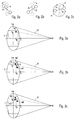
- FIGS. 3a to 3c briefly show the differences in Possibilities for creating additional marker arrangements Control signals are briefly explained.
- FIG. 3a shows a sketch for the use of a single active or passive marker M on the treatment instrument.
- the detection of this marker M permits the determination of its position within the area F placed in the viewing cone ⁇ of the camera K.
- the position of the marker M can then be converted into corresponding screen coordinates x p and y p for the pointer on the screen. Since there is only one marker M, additional control signals for simulating mouse clicks can only be generated by an additional input instrument - for example the foot switch - or by generating special light sequences.
- the orientation of the connecting straight line II relative to the x or y axis can also be determined.
- the angle ⁇ determined here can be used as described above - possibly with the help of a further switch or foot switch - to generate further control signals.
- the center between the two markers M1 and M2 is preferably chosen for the coordinates x p and y p of the pointer on the screen surface. If the two markers M1 and M2 are structurally identical, a reversal of their arrangement, which results, for example, when rotating through 180 °, cannot be detected, so that ambiguities can possibly arise.
- this arrangement has the disadvantage that the rotation of the instrument cannot be clearly determined, since the rotation of the instrument from any position results in exactly the same image of the marker arrangement.
- there is the possibility of avoiding this problem by designing or operating the markers in such a way that they can be clearly identified. This can be done, for example, using a different shape of the markers or by modulating the light signals emitted by the markers.
Abstract
Description
Die vorliegende Erfindung betrifft eine zahnmedizinische Einrichtung sowie ein Verfahren zum effektiven Steuern dieser Einrichtung.The present invention relates to a dental device and a Procedure for effectively controlling this facility.
Bei modernen medizinischen Einrichtungen muß oftmals eine Vielzahl von Funktionen der medizinischen Gerätschaften mit Hilfe unterschiedlicher Steuereinrichtungen angesteuert werden. Beispielsweise werden im Laufe einer komplexen Behandlung mit mehreren aufeinanderfolgenden Behandlungsschritten die Betriebsparameter der unterschiedlichen Gerätschaften für jeden Behandlungsschritt speziell gewählt. Dabei sind den Gerätschaften sowohl die Behandlungsinstrumente selbst als auch beispielsweise der Patientenstuhl oder weitere Hilfseinrichtungen zuzurechnen.Modern medical facilities often have a variety of functions of medical devices with the help of different control devices can be controlled. For example, in the course of a complex treatment several successive treatment steps, the operating parameters of the different devices specially selected for each treatment step. there are both the treatment instruments themselves and the equipment for example the patient chair or other auxiliary facilities.
Mehrere Veröffentlichungen befassen sich mit einem einfachen und effektiven Ansteuern der unterschiedlichen Funktionen von medizinischen Einrichtungen. Dabei ist insbesondere bei zahnmedizinischen Einrichtungen der Fußschalter die nach wie vor am häufigsten verwendete Eingabevorrichtung. Weiterentwicklungen des klassischen Fußschalters sind beispielsweise aus der EP 0 525 539 A2 bekannt. Dabei werden über Drucksensoren die Belastungen der Oberfläche des Fußschalters in primäre elektrische Signale umgewandelt, die mittels einer Signalauswerteelektronik in Steuersignale umgewandelt und auf eine zentrale Steuereinheit übertragen werden. Auf diese Weise wird eine zahnärztliche Behandlungseinrichtung mit einem Patientenstuhl und mehreren Dentalgeräten gesteuert. Eine in der EP 0 455 852 B1 beschriebene zahnärztliche Einrichtung weist ferner eine Anzeigeeinrichtung auf, auf der sämtliche wichtigen Funktionen der Einrichtung dargestellt werden. Das Bedienen der unterschiedlichen Funktionen wird lediglich durch ein einziges Eingabeinstrument, nämlich einen in zwei Freiheitsgraden verstellbaren Fußschalter ermöglicht. Auch die in der EP 0 391 967 B1 offenbarte zahnärztliche Vorrichtung ermöglicht eine Steuerung sämtlicher Operationen und Hilfsfunktionen über lediglich einen einzigen Fußschalter.Several publications deal with a simple and effective Control of the different functions of medical facilities. It is especially in dental facilities the footswitch is still on most commonly used input device. Further developments of the classic Foot switches are known for example from EP 0 525 539 A2. Doing so will Pressure sensors load the surface of the foot switch in primary electrical Signals converted into control signals by means of signal evaluation electronics converted and transferred to a central control unit. In this way becomes a dental treatment facility with one patient chair and several Dental equipment controlled. A dental described in EP 0 455 852 B1 Device also has a display device on which all important Functions of the facility are shown. Operating the different Functions are performed only by a single input instrument, namely one in two Adjustable foot switch allows degrees of freedom. Also in EP 0 391 967 B1 disclosed dental device enables control of all operations and auxiliary functions via just a single foot switch.
Da zahnärztliche Behandlungsplätze immer komplexer und vielfältiger aufgebaut werden, ist die Steuerung sämtlicher Funktionen eines Behandlungsplatzes durch einen einzigen Fußschalter immer schwieriger zu bewerkstelligen. Die Möglichkeiten eines Fußschalters als Steuereinrichtung sind nämlich aufgrund der Bedienung mit den Füßen und der zur Verfügung stehenden Freiheitsgrade begrenzt. Oftmals ist es erforderlich, zum Ändern eines einzigen Parameters eine Reihe von Untermenüs anzuwählen, bis schließlich die gewünschte Änderung durchgeführt werden kann. Die hierfür benötigten zahlreichen Eingabeschritte und der damit verbundene Zeitaufwand können allerdings nicht unbedingt als sehr bedienungsfreundlich angesehen werden. Because dental treatment centers are becoming increasingly complex and diverse are the control of all functions of a treatment center by one single foot switch increasingly difficult to accomplish. The possibilities of one Foot switches as a control device are namely due to the operation with the feet and the degrees of freedom available. It is often necessary select a series of submenus to change a single parameter until finally the desired change can be made. The necessary for this Numerous input steps and the associated time expenditure can, however not necessarily considered to be very easy to use.
Die in der DE 296 21 939 U1 beschriebene medizinischen Einrichtung weist daher eine Eingabevorrichtung auf, welche ein Zeigegerät, vorzugsweise ein Mauspad mit Druck- und Positionssensorik enthält, über das von Hand die verschiedenen Funktionen der Einrichtung, deren entsprechende Parameter auf einer Anzeigeeinheit dargestellt werden, gesteuert werden. Als weiteres Eingabegerät wird ein Fußschalter verwendet, über den die Steuerung des gerade verwendeten Behandlüngsinstruments erfolgt.The medical device described in DE 296 21 939 U1 therefore has one Input device on which a pointing device, preferably a mouse pad with printing and Contains position sensors, by means of which the various functions of the Facility whose corresponding parameters are shown on a display unit be controlled. A foot switch is used as an additional input device, which is used to control the treatment instrument currently in use.
Aus der Neurochirurgie ist schließlich die Positions-Erfassung von medizinischen Behandlungsinstrumenten bekannt. Bei in diesem Bereich durchgeführten Operationen ist es oftmals unerläßlich, die exakte Position des Behandlungsinstruments relativ zur Anatomie des Patienten zu kennen, um die Operation auch tatsächlich mit hoher Genauigkeit an der zu behandelnden Stelle durchführen zu können. Neuchirugische Behandlungseinrichtungen weisen daher grundsätzlich ein Behandlungsinstrument sowie eine Anzeigeeinheit und Mittel zum Erfassen der Position des Behandlungsinstruments auf, wobei während der Behandlung permanent die Position des Behandlungsinstruments relativ zur Anatomie des Patienten auf der Anzeigeeinheit dargestellt wird. Das Überwachen und Darstellen der Position des Behandlungsinstruments erfolgt über die Steuersoftware der Behandlungseinrichtung.The position detection of medical is from neurosurgery Treatment instruments known. For operations performed in this area it is often essential to determine the exact position of the treatment instrument relative to the Knowing the patient's anatomy to actually perform the surgery with high To be able to perform accuracy at the area to be treated. New Surgical Treatment facilities therefore basically have a treatment instrument as well a display unit and means for detecting the position of the treatment instrument on, during the treatment the position of the Treatment instrument relative to the patient's anatomy on the display unit is pictured. Monitoring and displaying the position of the Treatment instrument takes place via the control software of the treatment facility.
In der US 5,230,623 wird vorgeschlagen, die Steuersoftware einer neurochirurgischen Behandlungseinrichtung derart zu erweitern, daß die von dem Behandlungsinstrument permanent abgegebenen Steuersignale vorübergehend auch zum Bedienen eines auf der Anzeigeeinheit dargestellten Menüs verwendet werden. Auf diese Weise können unterschiedliche Funktionen der Behandlungseinrichtung angewählt werden. Da die hardware- und softwaremäßigen Voraussetzungen zum Erfassen der Position des Behandlungsinstruments bzw. zum Umsetzen der räumlichen Position in Steuersignale ohnehin vorhanden sind, müssen dafür lediglich geringfügige Änderungen in der Steuersoftware vorgenommen werden.US 5,230,623 proposes the control software of a neurosurgical To expand the treatment facility so that the treatment instrument Control signals permanently emitted temporarily also for operating one on the Display unit shown menus are used. That way you can different functions of the treatment facility can be selected. Since the Hardware and software requirements for detecting the position of the Treatment instrument or to convert the spatial position into control signals already exist, you only need to make minor changes in the Control software can be made.
Im Gegensatz dazu hat die vorliegende Erfindung zum Ziel, eine zahnmedizinische Einrichtung hardwaremäßig derart zu erweitern, daß herkömmliche Behandlungsinstrumente zusätzlich auch als Eingabevorrichtungen zum Steuern der gesamten Einrichtung verwendet werden können.In contrast, the present invention aims to provide a dental Hardware to expand such that conventional Treatment instruments also as input devices for controlling the entire facility can be used.
Es ist somit Aufgabe der vorliegenden Erfindung eine zahnmedizinische Einrichtung anzugeben, bei der die zahlreichen Funktionen der Gerätschaften auf eine neue und möglichst benutzerfreundliche und effektive Weise angesteuert werden können. It is therefore an object of the present invention to provide a dental device to specify, in which the numerous functions of the equipment on a new and can be controlled as user-friendly and effective as possible.
Die Aufgabe wird durch eine Einrichtung, welche die Merkmale des Anspruches 1 aufweist, gelöst.The object is achieved by a device which has the features of claim 1 has, solved.
Die Einrichtung weist mindestens ein Behandlungsinstrument, eine zentrale Steuereinrichtung sowie eine Anzeigeeinheit auf, auf der beispielsweise unterschiedliche Betriebsparameter und Funktionen der Einrichtung dargestellt werden. Erfindungsgemäß weist die Einrichtung ferner Mittel zum Erfassen der räumlichen Position des Behandlungsinstrumentes auf. Zum Ändern bestimmter auf der Anzeigeeinheit dargestellter Betriebsparameter oder zum Anwählen einer Funktion wird dann in einem Steuermodus die räumliche Position des Behandlungsinstruments in Steuersignale für einen auf der Anzeigeeinheit bewegbaren Zeiger umgesetzt. Das Behandlungsinstrument übernimmt somit während des Steuermodus die Funktion einer Einabevorrichtung, wobei die Funktionsweise derjenigen einer Computer-Maus entspricht, so daß die gesamte zahnmedizinische Einrichtung berührungslos und komfortabel bedient werden kann. Zum Aufrufen einer bestimmten Funktion oder zum Ändern eines Betriebsparameters ist es daher nicht mehr notwendig, das Behandlungsinstrument abzulegen, um ein spezielles Eingabeeinstrument zu betätigen. Dadurch wird auch die Gefahr vermieden, ein oftmals sehr schwierig zu reinigendes bzw. zu desinfizierendes Eingabeinstrument - beispielsweise eine Tastatur - zu kontaminieren.The device has at least one treatment instrument, a central one Control device and a display unit on which, for example, different Operating parameters and functions of the facility are shown. According to the invention, the device also has means for detecting the spatial Position of the treatment instrument. To change certain on the Display operating parameters displayed or to select a function then in a control mode the spatial position of the treatment instrument in Control signals implemented for a pointer movable on the display unit. The Treatment instrument thus takes over the function of a during the control mode Input device, the mode of operation of that of a computer mouse corresponds so that the entire dental facility is contactless and can be operated comfortably. To call up a specific function or to It is therefore no longer necessary to change an operating parameter Put down the treatment instrument to operate a special input instrument. This also avoids the risk of often being very difficult to clean or input instrument to be disinfected - for example a keyboard contaminate.
Unter dem oben erwähnten Behandlungsinstrument werden dabei sämtliche Instrumente eines zahnmedizinischen Behandlungsplatzes verstanden. Neben dem üblichen Bohrer kann es sich beispielsweise um eine intraorale Kamera, eine Meßsonde oder dergleichen handeln. Wesentlich dabei ist, daß eine Positionsbestimmung dieser Instrumente aufgrund ihrer Funktionsweise von Haus aus nicht möglich bzw. notwendig ist, daß diese aber entsprechend der Erfindung nun zusätzlich die Funktion eines Eingabeinstruments erfüllen können.All instruments are included under the treatment instrument mentioned above a dental treatment center understood. In addition to the usual drill it can be, for example, an intraoral camera, a measuring probe or the like act. It is essential that a position determination of these instruments due to their mode of operation, it is not possible or necessary that but according to the invention this now also has the function of a Can meet input instrument.
Weiterbildungen der Erfindung sind Gegenstand der Unteransprüche. So können zur Ermittlung der räumlichen Position des Zeigeinstruments alle bekannten Technologien verwendet werden, z.B. die in den Offenlegungsschriften EP 0 789 320 A2, EP 0 526 015 A1 und DE 38 38 605 A1 beschriebene Positionsbestimmung mittels Illtraschallimpulsen. Vorzugesweise wird die Position jedoch durch Emittieren und Empfangen von Infrarotstrahlung erfaßt. Beispielsweise kann dafür an der Anzeigeeinheit eine Infrarot-Lichtquelle vorgesehen sein. Die von dieser Lichtquelle emittierte Strahlung wird dann von einem an dem Behandlungsinstrument angebrachten passiven Marker (Reflektor) reflektiert und von einem wiederum an der Anzeigeeinheit vorgesehenen optischen Sensor - beispielsweise einer Kamera oder einer 4-Felder-Photodiode - erfaßt. Alternativ dazu kann auch eine aktive Infrarot-Lichtquelle direkt an dem Behandlungsinstrument angeordnet werden, wobei dann auf die Lichtquellen an der Anzeigeeinheit verzichtet werden kann. Die von dem optischen Sensor detektierten Koordinaten der Lichtquelle bzw. des Reflektors an dem Behandlungsinstrument werden dann in kartesische Koordinaten auf der Anzeigeeinheit umgerechnet, wodurch die Position des Zeigers durch einfaches Bewegen des Behandlungsinstruments verändert werden kann.Developments of the invention are the subject of the dependent claims. So can Determination of the spatial position of the pointing instrument all known technologies be used, e.g. those in the published patent applications EP 0 789 320 A2, EP 0 526 015 A1 and DE 38 38 605 A1 determine the position by means of Illuminated impulses. However, the position is preferably determined by issuing and Receiving infrared radiation detected. For example, at the Display unit an infrared light source may be provided. The one from this light source emitted radiation is then applied to the treatment instrument by one passive marker (reflector) reflected and in turn by the display unit provided optical sensor - for example a camera or a 4-field photodiode - detected. Alternatively, an active infrared light source can be attached directly the treatment instrument can be arranged, then on the light sources on the Display unit can be dispensed with. Those detected by the optical sensor Coordinates of the light source or the reflector on the treatment instrument then converted into Cartesian coordinates on the display unit, whereby the Position of the pointer changed by simply moving the treatment instrument can be.
Da erfindungsgemäß das Behandlungsinstrument die Funktion einer Maus übernehmen soll, ist es vorteilhaft, wenn neben den Signalen zum Bewegen des Zeigers weitere Steuersignale, die beispielsweise dem Drücken einer linken oder rechen Maustaste entsprechen, erzeugt werden können. Hierfür kann beispielsweise die zusätzliche Verwendung eines Fußschalters vorgesehen sein.Since, according to the invention, the treatment instrument takes on the function of a mouse , it is advantageous if, in addition to the signals for moving the pointer, further Control signals, such as pressing a left or right mouse button correspond, can be generated. For example, the additional Use of a foot switch can be provided.
In einer Grundausführung der vorliegenden Erfindung ist es ausreichend, wenn an dem Behandlungsinstrument lediglich ein aktiver (Infrarot-Lichtquelle) oder passiver (Reflektor) Marker angebracht ist. Die Möglichkeiten zum Erzeugen weiterer Steuersignale werden jedoch erhöht, wenn sich mindestens ein weiterer Marker an dem Behandlungsinstrument befindet, da nun die Möglichkeit gegeben ist, neben der Position des Instruments auch dessen räumliche Orientierung zu erfassen. Die räumliche Orientierung bzw. Änderungen davon können dann bei der Erzeugung von zusätzlichen Steuersignalen berücksichtigt werden. Werden an dem Behandlungsinstrument drei Marken angebracht, so kann die exakte 3-dimensionale Lage des Instruments erfaßt und zu Steuerzwecken ausgenutzt werden.In a basic embodiment of the present invention, it is sufficient if the Treatment instrument only an active (infrared light source) or passive (Reflector) marker is attached. The ways to create more Control signals are increased, however, if at least one additional marker is on the Treatment instrument is located, since there is now the possibility, next to the Position of the instrument also to record its spatial orientation. The spatial Orientation or changes can then be made when generating additional ones Control signals are taken into account. Be three on the treatment tool Marks attached, so the exact 3-dimensional position of the instrument can be recorded and be used for tax purposes.
Alternativ dazu besteht die Möglichkeit, mit den Markern an dem Behandlungsinstrument ein zeitlich veränderbares Signal zu erzeugen, welches von der Kamera detektiert und als zusätzliches Steuersignal interpretiert wird. Dieses zeitlich veränderbare Signal kann beispielsweise durch unterschiedliche An/Aus-Sequenzen der Lichtquelle bzw. der Reflexionseigenschaften des Reflektors gebildet werden. Das Auslösen derartiger Sequenzen kann beispielsweise über einen an dem Instrument angebrachten Schalter erfolgen. Ebenfalls läßt sich über ein zeitlich veränderbares Signal der Störabstand des Systems verbessern, da der Einfluß anderer Infrarotquellen (z.B. Reflexionen an einer Lampe oder einem Knopf) auf diese Weise minimiert wird.Alternatively, there is the option of using the markers on the Treatment instrument to generate a time-variable signal, which of the Camera is detected and interpreted as an additional control signal. This in time changeable signal can, for example, by different on / off sequences of the Light source or the reflection properties of the reflector are formed. The Such sequences can be triggered, for example, via a on the instrument attached switch. Can also be changed over time Signal improve the signal-to-noise ratio of the system because of the influence of other infrared sources (e.g. reflections from a lamp or a button) is minimized in this way.
Vorteilhaft soll parallel zu der Verwendung des Behandlungsinstruments als Eingabegerät immer noch die Verwendung einer herkömmlichen Maus möglich sein. It should advantageously be used in parallel with the use of the treatment instrument Input device can still use a conventional mouse.
Im folgenden soll die Erfindung anhand der beiliegenden Zeichnungen näher erläutert werden. Es zeigen:
- Fig. 1
- ein Ausführungsbeispiel einer erfindungsgemäßen zahnmedizinischen Einrichtung;
- Fig. 2a bis 2c
- schematische Darstellungen zur Erzeugung zusätzlicher Steuersignale bei der Verwendung von zwei Markern; und
- Fig. 3a bis 3c
- schematische Darstellungen unterschiedlicher Markeranordnungen.
- Fig. 1
- an embodiment of a dental device according to the invention;
- 2a to 2c
- schematic representations for generating additional control signals when using two markers; and
- 3a to 3c
- schematic representations of different marker arrangements.
Der allgemeine Aufbau eines zahnmedizinischen Behandlungsplatzes ist aus dem Stand der Technik bereits hinlänglich bekannt. In Fig. 1 werden daher lediglich die für die Erfindung wesentlichen Elemente dargestellt. Diese sind ein Behandlungsinstrument 1 - im dargestellten Beispiel ein Bohrer - sowie eine Anzeigeeinheit (Monitor) 2 und eine nicht dargestellte zentrale Steuereinrichtung. Auf dem Bildschirm des Monitors 2 können beispielsweise die Betriebsdaten des jeweils im Einsatz befindlichen Behandlungsinstrumentes 1, Wartungshinweise, Patientendaten in Text und/oder Bild und verschiedene einstellbare und fest vorgegebene Funktionen des Behandlungsplatzes, sowie beliebige Computerprogramme angezeigt werden. Um eine übersichtliche Darstellung zu ermöglichen, können mit Hilfe eines Menüs 7 unterschiedliche Funktionen aufgerufen werden. Dabei ist auch die Möglichkeit gegeben, für eine in mehreren Schritten durchzuführende Behandlung für jeden Schritt bereits zuvor einprogrammierte Betriebsparameter und Funktionen anzuwählen. Das Anwählen bestimmter Funktionen und das Verändern von Betriebsparametern erfolgt durch Anwählen der entsprechenden Symbole auf der Bildschirmoberfläche durch den Zeiger 3.The general structure of a dental treatment center is up to date already well known in the art. In Fig. 1, therefore, only those for Invention essential elements shown. These are a treatment tool 1 - In the example shown, a drill - and a display unit (monitor) 2 and one Central control device, not shown. On the monitor screen 2 can, for example, the operating data of the one in use Treatment instrument 1, maintenance instructions, patient data in text and / or image and various adjustable and fixed functions of the treatment center, as well as any computer programs are displayed. To be clear To enable display, 7 different can be done using a menu Functions can be called. There is also the possibility for an in treatment to be carried out in several steps for each step beforehand select programmed operating parameters and functions. Dialing certain functions and changing operating parameters is done by Use the pointer to select the corresponding symbols on the screen surface 3rd
Erfindungsgemäß wird der Zeiger 3 in einem Steuermodus mit Hilfe des als Eingabevorrichtung dienenden Behandlungsinstruments 1 angesteuert. Zu diesem Zweck sind an dem Behandlungsinstrument 2 zwei passive Infrarotmarker (Reflektoren) 4 angebracht. An der Unterseite des Bildschirms 2 befinden sich zwei Infrarot-Lichtquellen 5 - beispielsweise IR-LEDs - über welche das Instrument 1 beleuchtet wird. Die Reflexionen des Infrarotlichtes durch die beiden auf dem Behandlungsinstrument 1 angeordneten Marker 4 wird durch eine ebenfalls an der Unterseite des Bildschirms 2 angebrachte infrarot-empfindliche Kamera 6 detektiert. Vorzugsweise wird die Kamera 6 mit einem Tageslichtsperrfilter 8 versehen, um den Störabstand gegenüber Umwelteinflüssen zu vergrößern. Der von der Kamera 6 erfaßbare Raumwinkel Ω ist mit dem von den beiden Lichtquellen 5 bestrahlten Bereich identisch.According to the invention, the pointer 3 is in a control mode using the as Treatment device 1 serving input device. To this end are two passive infrared markers (reflectors) 4 on the treatment instrument 2 appropriate. At the bottom of the screen 2 there are two infrared light sources 5 - for example IR LEDs - via which the instrument 1 is illuminated becomes. The reflections of the infrared light by the two on the Treatment instrument 1 arranged marker 4 is also on the Underside of the screen 2 attached infrared-sensitive camera 6 detected. The camera 6 is preferably provided with a daylight blocking filter 8, around which To increase the signal-to-noise ratio from environmental influences. The one from the camera 6 detectable solid angle Ω is with the area irradiated by the two light sources 5 identical.
Im Folgenden soll die Funktionsweise der Kamera 6 näher erläutert werden. Durch die Kamera 6 werden die beiden Marker 4 detektiert und deren auf die optische Achse I der Kamera 6 bezogene Kugelkoordinaten berechnet. Dabei kann der Abstand des Behandlungsinstruments 1 von der Kamera 6 innerhalb bestimmter Grenzen beliebig gewählt werden. Die berechneten Kugelkoordinaten werden dann von der Steuereinheit auf kartesische Koordinaten für die Bildschirmoberfläche umgerechnet und der Zeiger 3 in der entsprechenden Position dargestellt. Auf diese Weise kann während des Steuermodus durch einfaches Bewegen des Behandlungsinstrumentes 1 der Zeiger 3 über die Oberfläche des Bildschirms 2 bewegt werden. Die Empfindlichkeit bei der Umsetzung auf die kartesischen Koordinaten ist dabei umgekehrt proportional zum Abstand der beiden Marker 4 von der Kamera 6 und kann somit von dem Anwender gezielt variiert werden. Um schnelle und damit auch grobe Bewegungen des Zeigers 3 durchzuführen, muß sich das Behandlungsinstrument 1 in einem nur geringen Abstand von der Kamera 6 befinden, während bei größerem Abstand langsame aber dafür genaue Bewegungen des Zeigers 3 erzielt werden können.The mode of operation of the camera 6 will be explained in more detail below. Through the Camera 6, the two markers 4 are detected and their on the optical axis I of the Camera 6 related spherical coordinates calculated. The distance of the Treatment instrument 1 from the camera 6 within certain limits to get voted. The calculated spherical coordinates are then used by the control unit converted to Cartesian coordinates for the screen surface and the pointer 3 shown in the appropriate position. This way, during the Control mode by simply moving the treatment instrument 1, the pointer 3 are moved over the surface of the screen 2. The sensitivity at the Implementation on the Cartesian coordinates is inversely proportional to Distance of the two markers 4 from the camera 6 and can therefore be by the user be varied in a targeted manner. For quick and therefore rough movements of the pointer 3 perform, the treatment instrument 1 must be only a short distance from the camera 6, while at a greater distance slow but for it precise movements of the pointer 3 can be achieved.
Die Bewegung des Zeigers 3 durch das Behandlungsinstrument 1 kann absolut oder relativ erfolgen. Im ersten Fall entspricht jeder Position des Behandlungsinstruments 1 in dem von der Kamera 6 erfaßten Raumbereich Ω exakt eine Koordinate des Zeigers 3 auf dem Bildschirm. Im zweiten Fall wird die Position des Zeigers 3 durch die Bewegung des Behandlungsinstruments 1 relativ zur Position des Zeigers 3 zu Beginn des Steuermodus verändert. Dieser Fall entspricht dem Verhalten einer üblichen Maus. Das zwischenzeitliche Aussetzen der Zeigerbewegung, welches bei der normalen Computer-Maus durch Anheben erfolgt, kann durch einen zusätzlichen Schalter oder durch Ignorieren von sehr schnellen Bewegungen simuliert werden.The movement of the pointer 3 through the treatment instrument 1 can be absolute or relatively. In the first case, each position of the treatment instrument corresponds to 1 in the spatial area Ω captured by the camera 6, exactly one coordinate of the pointer 3 on the screen. In the second case, the position of the pointer 3 is determined by the Movement of the treatment instrument 1 relative to the position of the pointer 3 at the beginning the control mode changed. This case corresponds to the behavior of a normal mouse. The intermittent suspension of the pointer movement, which occurs during normal Computer mouse done by lifting, can be by an additional switch or can be simulated by ignoring very fast movements.
Alternativ zu der Kamera 6 könnten als optischer Sensor auch eine 4-Felder-Photodiode bzw. mehrere verteilt angeordnete Photodioden verwendet werden. Mit Hilfe einer Schwerpunktberechnung werden dann die erfaßten Signale in entsprechende Koordinaten umgesetzt.As an alternative to the camera 6, a 4-field photodiode could also be used as the optical sensor or several distributed photodiodes can be used. With the help of a The calculation of the center of gravity then converts the signals into corresponding ones Coordinates implemented.
Um beispielsweise eine der Funktionen des auf dem Bildschirm 2 dargestellten Menüs 7 anwählen zu können, muß ferner auch die Möglichkeit gegeben sein, zusätzliche Steuersignale, die beispielsweise einem Maus-Klick entsprechen, erzeugen zu können. Hierfür kann an dem Behandlungsinstrument 1 ein zusätzlicher Schalter 8 vorgesehen sein. Bei Betätigen dieses Schalters 8 werden dann z.B. entsprechende Steuersignale über den Verbindungsschlauch 9 an die zentrale Steuereinrichtung weitergeleitet. Alternativ dazu könnte auch vorgesehen sein, daß bei Betätigen des Schalters 8 ein zeitlich veränderbares Signal erzeugt wird, welches von der Kamera 6 detektiert und als entsprechender Maus-Klick interpretiert wird. Beispielsweise könnte durch Änderungen der Reflexionseigenschaften der Marker 4 mit Hilfe von Polarisationsfolien eine zeitliche An/Aus-Sequenz erzeugt werden.For example, one of the functions of the menu 7 shown on the screen 2 To be able to select, there must also be the possibility of additional To be able to generate control signals that correspond, for example, to a mouse click. For this purpose, an additional switch 8 can be provided on the treatment instrument 1 his. When this switch 8 is actuated, e.g. corresponding control signals passed on to the central control device via the connecting hose 9. Alternatively, it could also be provided that when the switch 8 is actuated, a Time-variable signal is generated, which is detected by the camera 6 and as corresponding mouse click is interpreted. For example, through changes the reflection properties of the marker 4 with the help of polarizing foils temporal on / off sequence are generated.
Weist der Schalter 8 zwei anzuwählende Schaltzustände auf, so können damit in einfacher Weise ein rechter und ein linker Maus-Klick nachgeahmt werden. Bietet der Schalter 8 jedoch nur die Möglichkeit eines einzigen Schaltzustandes, so kann zunächst lediglich ein Steuersignal erzeugt werden. In diesem Fall kann die Orientierung des Behandlungsinstruments 1 zusätzlich berücksichtigt werden. Zur Berechnung einer kartesischen Koordinate für den Zeiger 3 ist nämlich zunächst lediglich ein einziger Marker 4 ausreichend. Durch den zweiten Marker wird allerdings eine Gerade II definiert, deren vertikale Lage im Raum durch die zentrale Steuereinheit berechenbar ist. Die Ausrichtung der Projektion dieser Geraden II in eine senkrecht zur optischen Achse 1 der Kamera 6 stehenden Fläche F kann dann für zusätzliche Steuerfunktionen ausgewertet werden. Beispielsweise kann aufgrund der Ausrichtung der Geraden II zwischen einem rechten oder linken Maus-Klick unterschieden werden. Vorzugsweise wird jedoch nicht die absolute Orientierung des Behandlungsinstruments 1 sondern eine Änderung der Orientierung zum Erzeugen der zusätzlichen Steuersignale verwendet. Beispielsweise kann vorgesehen sein, daß nach Betätigen des Schalters 8 unterschieden wird, ob das Behandlungsinstrument 1 im Uhrzeigersinn oder gegen den Uhrzeigersinn gedreht wird, was dann jeweils dem rechten oder dem linken Maus-Klick entspricht. Dies ist in den Figuren 2a und 2b dargestellt, wobei A jeweils die Orientierung der Instrumenten-Achse vor und B deren Orientierung nach der Drehung bezeichnet. Dementsprechend wird die in Fig. 2a dargestellte Drehung entgegen dem Uhrzeigersinn einem Klick einer linken Maustaste und die in Fig. 2b dargestellte Drehung einem rechten Maus-Klick zugeordnet.If the switch 8 has two switching states to be selected, then in a right and a left mouse click can be easily mimicked. Does the offer Switch 8, however, only the possibility of a single switching state, so initially only a control signal can be generated. In this case, the orientation of the Treatment instrument 1 are also taken into account. To calculate a Cartesian coordinate for pointer 3 is initially only a single one Marker 4 sufficient. However, the second marker makes a straight line II defined, whose vertical position in the room can be calculated by the central control unit is. The alignment of the projection of this straight line II in a perpendicular to the optical Axis 1 of the camera 6 standing surface F can then be used for additional control functions be evaluated. For example, due to the alignment of the straight line II distinguish between a right or left mouse click. Preferably However, not the absolute orientation of the treatment instrument 1 but one Change of orientation used to generate the additional control signals. For example, it can be provided that a distinction is made after actuation of the switch 8 whether the treatment instrument 1 is clockwise or counterclockwise is rotated, which then corresponds to the right or left mouse click. This is shown in Figures 2a and 2b, where A is the orientation of each Instrument axis before and B designated their orientation after rotation. Accordingly, the rotation shown in Fig. 2a becomes counterclockwise a click of a left mouse button and the rotation shown in Fig. 2b one assigned to the right mouse click.
Da allerdings die Gefahr besteht, daß beim Drehen des Behandlungsinstruments 1 auch der Zeiger 3 verschoben wird, kann vorgesehen sein, daß während einer Betätigung des Schalters 8 der Zeiger 3 nicht mehr bewegt wird, sondern nur noch zwischen den unterschiedlichen Drehrichtungen des Instruments 1 unterschieden wird. Wird das Instrument 1 mit drei Markern 4 ausgestattet, so läßt sich auch die absolute Lage des Instruments 1 (nach links oder rechts gedreht) verwenden und einem entsprechenden Klick der linken oder rechten Maustaste zuordnen. However, since there is a risk that when turning the treatment instrument 1 also the pointer 3 is moved, it can be provided that during an operation of the Switch 8 of the pointer 3 is no longer moved, but only between the different directions of rotation of the instrument 1 is distinguished. Will that Instrument 1 equipped with three markers 4, so the absolute location of the Use Instruments 1 (turned left or right) and a corresponding one Click left or right mouse button to assign.
Eine weitere Möglichkeit besteht darin, zum Erzeugen der zusätzlichen Steuersignale
einen mit der zentralen Steuereinheit und dem Monitor 2 verbundenen Fußschalter 10
zu verwenden. In diesem Fall kann auf den Schalter 8 an dem Behandlungsinstrument 1
verzichtet werden. Weist der Fußschalter 10 lediglich eine Schaltfläche auf, so können
wie eben beschrieben mit Hilfe von Drehbewegungen des Behandlungsinstruments 1
unterschiedliche Steuersignale erzeugt werden.Another possibility is to generate the additional control signals
a
Der Fußschalter 10 bzw. der Schalter 8 am Behandlungsinstrument 1 kann auch dafür
verwendet werden, den Steuermodus zu aktivieren. Alternativ dazu kann festgelegt
werden, daß der Steuermodus aktiviert wird, sobald Signale der Marker 4 über die
Dauer eines vordefinierten und einstellbaren Zeitfensters von der Kamera 6 detektiert
werden. Ist dieser Steuermodus aktiviert, so kann der Fußschalter 10 für die Erzeugung
der zusätzlichen Steuersignale verwendet werden. Nach Beenden des Steuermodus
nimmt er wieder seine gewohnten, vom jeweiligen aktivierten Instrument abhängigen
Funktionen (Anlasser usw.) war.The
Anstelle der Verwendung von passiven Markern 4 können auch aktive Lichtquellen an dem Behandlungsinstrument 1 vorgesehen werden, wobei dann auf die Infrarot-Lichtquellen 5 an der Anzeigeeinheit 2 verzichtet werden kann. Die Marker werden dann vorzugsweise in die Kupplung zwischen dem aufsteckbaren Instrument und dem Versorgungsschlauch integriert, da zum einen dann eine entsprechende Stromversorgung zur Verfügung steht und da zum anderen die Instrumente selbst nicht neu konstruiert werden müssen. Bei passiven Markern kann hingegen auch eine separate Haltevorrichtung verwendet werden, beispielsweise in Form eines Klemmringes oder dergleichen, die auf das Behandlungsinstrument aufgesteckt oder aufgeschoben wird.Instead of using passive markers 4, active light sources can also be used the treatment instrument 1 can be provided, then on the infrared light sources 5 on the display unit 2 can be omitted. The markers will then preferably in the coupling between the attachable instrument and the Integrated supply hose, because on the one hand a corresponding one Power supply is available and because the instruments themselves are not have to be redesigned. With passive markers, however, a separate one can also be used Holding device can be used, for example in the form of a clamping ring or the like, which is attached or pushed onto the treatment instrument.
Ferner können anstelle von einem oder zwei Markern auch drei Marker an dem Instrument 1 angebracht sein, was dann von Vorteil ist, wenn die exakte 3-dimensionale Anordnung des Behandlungsinstruments 1 zum Erzeugen zusätzlicher Steuersignale ausgenutzt werden soll. Befinden sich drei Marker in einer Dreiecksanordnung (wobei es sich dabei nicht um ein gleichseitiges Dreieck handeln darf) so kann die absolute Orientierung des Instrumentes 1 im Raum bestimmt werden. Im Gegensatz dazu ergeben sich bei der Verwendung von lediglich zwei Markern Mehrdeutigkeiten, da um 180° gedrehte Positionen nicht unterschieden werden können. Wie beispielhaft in Fig. 2c dargestellt ist, besteht die Gefahr, daß sich aus der Endposition B nicht mehr ableiten läßt, ob eine Linksdrehung a oder Rechtsdrehung b erfolgte.Furthermore, instead of one or two markers, three markers on the Instrument 1 can be attached, which is advantageous if the exact 3-dimensional Arrangement of the treatment instrument 1 for generating additional control signals should be exploited. If there are three markers in a triangular arrangement (where it must not be an equilateral triangle), the absolute Orientation of the instrument 1 can be determined in space. In contrast to ambiguities arise when using only two markers, because um 180 ° rotated positions cannot be differentiated. As exemplified in Fig. 2c, there is a risk that no longer derive from the end position B. leaves whether a left turn a or a right turn b took place.
Bei der Verwendung von drei Markern oder von zwei räumlich getrennten Bildsensoren besteht ferner die Möglichkeit, die 3. Dimension zur Bedienung der Behandlungseinheit zu verwenden. Beispielsweise können von der Entfernung des Behandlungsinstruments 1 von der Anzeigeeinheit 2 abhängig automatisch unterschiedliche Funktionen des Arbeitsplatzes gesteuert werden; befindet sich das Behandlungsinstrument 1 nahe an der Anzeigeeinheit 2 kann z.B. der Patientenstuhl gesteuert werden, bei mittlerer Entfernung wird automatisch eine Steuermenü für eine Kameraaufnahme geöffnet und bei großem Abstand wird eine Menüoberfläche für die Leistungserfassung dargestellt. Auf diese Weise würde das Umschalten zwischen verschiedenen Menüoberflächen oder das Blättern innerhalb eines Programmes vereinfacht.When using three markers or two spatially separated image sensors there is also the possibility of the 3rd dimension for operating the treatment center to use. For example, from the removal of the treatment tool 1 depending on the display unit 2 automatically different functions of the Workplace are controlled; the treatment instrument 1 is close to the Display unit 2 can e.g. the patient chair can be controlled at medium A control menu for a camera shot is automatically opened and removed if there is a large distance, a menu interface for the service entry is displayed. This would switch between different menu interfaces or browsing within a program is simplified.
Um den Maus-Klicks entsprechende Steuersignale oder aber auch darüber hinaus weitere Steuersignale zu erzeugen, kann an der Behandlungseinheit ferner ein Spracherkennungsmodul vorgesehen sein.Control signals corresponding to the mouse clicks or even beyond Generating further control signals can also be performed on the treatment unit Speech recognition module can be provided.
Wurde die entsprechende Funktion auf der Bildschirmoberfläche mit Hilfe des als Eingabeinstrument fungierenden Behandlungsinstruments 1 durchgeführt, kann der Steuermodus deaktiviert werden und das Behandlungsinstrument 1 wieder in seiner ursprünglichen Funktion in gewohnter Weise verwendet werden. Enthält die zahnmedizinische Einrichtung mehrere Behandlungsinstrumente, so kann jedes dieser Instrumente während des Steuermodus als Eingabeinstrument fungieren. Weisen die Instrumente passive Marker auf, so werden die Marker der sich in der Instrumentenablage befindenden Instrumente ohnehin verdeckt, so daß diese nicht zu einem störenden Signal führen können. Sind jeweils aktive Marker vorhanden, so können in der Instrumentenablage Sensoren angebracht werden, die lediglich das Erzeugen von Infrarotsignalen bei Markern eines entnommenen Instruments ermöglichen.Was the corresponding function on the screen surface using the as Input instrument functioning treatment instrument 1 performed, the Control mode can be deactivated and the treatment instrument 1 back in its original function can be used in the usual way. Contains the Dental establishment has multiple treatment tools, so each of these Instruments act as input instruments during control mode. Assign the If passive markers are used on instruments, the markers located in the Instrument tray located instruments covered anyway, so that they are not too can lead to a disturbing signal. If there are active markers, see above can be attached to the instrument tray sensors that only Generation of infrared signals at markers of a removed instrument enable.
Somit kann die gesamte zahnmedizinische Einrichtung in einfacher und effektiver Weise berührungslos gesteuert werden. Ferner sind auch keine zusätzlichen Eingabegeräte notwendig, die der Zahnarzt mit seinen möglicherweise kontaminierten Fingern betätigen muß, da er das Behandlungsinstrument 1 kontinuierlich in der Hand behalten kann. Bei der Verwendung von passiven Markern können die Behandlungsinstrumente 1 auch ohne größere Schwierigkeiten gereinigt und sterilisiert werden. Vorzugsweise weist die zahnmedizinische Einrichtung allerdings auch eine herkömmliche Maus auf, die parallel zu dem Behandlungsinstrument 1 als Eingabeinstrument verwendet werden kann.Thus, the entire dental facility can be done in a simple and effective manner can be controlled without contact. Furthermore, there are no additional input devices necessary, which the dentist with his possibly contaminated fingers must actuate, as he continuously holds the treatment instrument 1 in his hand can. When using passive markers, the treatment instruments 1 can also be cleaned and sterilized without major difficulties. Preferably however, the dental facility also has a conventional mouse, which are used in parallel to the treatment instrument 1 as an input instrument can.
Im folgenden sollen anhand der Figuren 3a bis 3c kurz die sich bei unterschiedlichen Markeranordnungen ergebenden Möglichkeiten zum Erzeugen von zusätzlichen Steuersignalen kurz erläutert werden. In the following, FIGS. 3a to 3c briefly show the differences in Possibilities for creating additional marker arrangements Control signals are briefly explained.
Fig. 3a zeigt eine Skizze für die Verwendung eines einzelnen aktiven oder passiven Markers M an dem Behandlungsinstrument. Die Detektierung dieses Markers M erlaubt die Festlegung von dessen Position innerhalb der in den Blickkegel Ω der Kamera K gelegten Fläche F. Die Position des Markers M kann dann in entsprechende Bildschirmkoordinaten xp und yp für den Zeiger auf dem Bildschirm umgerechnet werden. Da lediglich ein Marker M vorhanden ist, können zusätzliche Steuersignale zum Simulieren von Maus-Klicks lediglich durch ein zusätzliches Eingabeinstrument - beispielsweise den Fußschalter - oder durch Erzeugen von speziellen Lichtsequenzen erzeugt werden.3a shows a sketch for the use of a single active or passive marker M on the treatment instrument. The detection of this marker M permits the determination of its position within the area F placed in the viewing cone Ω of the camera K. The position of the marker M can then be converted into corresponding screen coordinates x p and y p for the pointer on the screen. Since there is only one marker M, additional control signals for simulating mouse clicks can only be generated by an additional input instrument - for example the foot switch - or by generating special light sequences.
Bei dem in Fig. 3b dargestellten Beispiel mit zwei Markern M1 und M2 kann zusätzlich zur Positionsbestimmung der beiden Marker auch noch die Orientierung der Verbindungsgeraden II relativ zur x- oder zur y-Achse ermittelt werden. Der dabei bestimmt Winkel ϕ kann wie zuvor beschrieben - evtl. mit Hilfe eines weiteren Schalters oder Fußschalters - zur Erzeugung weiterer Steuersignale verwendet werden. Für die Koordinaten xp und yp des Zeigers auf der Bildschirmoberfläche wird vorzugsweise der Mittelpunkt zwischen den beiden Markern M1 und M2 gewählt. Falls die beiden Marker M1 und M2 baugleich sind, kann eine Vertauschung ihrer Anordnung, die sich beispielsweise bei einer Drehung um 180° ergibt, allerdings nicht erfaßt werden, so daß sich möglicherweise Mehrdeutigkeiten ergeben können. Wie bereits erwähnt wurde, besitzt diese Anordnung daher den Nachteil, daß sich die Drehung des Instruments nicht eindeutig bestimmen läßt, da bei einer Drehung aus jeder beliebigen Position um 180° exakt das gleiche Abbild der Markeranordnung entsteht. Es besteht aber die Möglichkeit, dieses Problem zu umgehen, indem die Marker so ausgebildet oder betrieben werden, daß sie sich eindeutig identifizieren lassen. Dies kann beispielsweise über eine unterschiedliche Form der Marker oder durch Modulation der von den Markern emittierten Lichtsignale erfolgen.In the example shown in FIG. 3b with two markers M1 and M2, in addition to determining the position of the two markers, the orientation of the connecting straight line II relative to the x or y axis can also be determined. The angle ϕ determined here can be used as described above - possibly with the help of a further switch or foot switch - to generate further control signals. The center between the two markers M1 and M2 is preferably chosen for the coordinates x p and y p of the pointer on the screen surface. If the two markers M1 and M2 are structurally identical, a reversal of their arrangement, which results, for example, when rotating through 180 °, cannot be detected, so that ambiguities can possibly arise. As has already been mentioned, this arrangement has the disadvantage that the rotation of the instrument cannot be clearly determined, since the rotation of the instrument from any position results in exactly the same image of the marker arrangement. However, there is the possibility of avoiding this problem by designing or operating the markers in such a way that they can be clearly identified. This can be done, for example, using a different shape of the markers or by modulating the light signals emitted by the markers.
Die zuvor beschriebenen Mehrdeutigkeiten können schließlich bei dem in Fig. 2c dargestellten Beispiel durch die Verwendung von drei Markern M1 bis M3 ausgeschlossen werden, da nun die exakte Orientierung und Position des Instruments im Raum bestimmt werden kann. Auch hier bietet sich die Möglichkeit, unterschiedliche Orientierungen zur Erzeugung von zusätzlichen Steuerungsfunktionen zu verwenden. Da bei einer zahnmedizinischen Einrichtung in der Regel ohnehin ein Fußschalter vorhanden ist, ist allerdings der Verwendung von einem einzigen oder zwei Markern der Vorzug zu geben.The ambiguities described above can finally in the in Fig. 2c illustrated example by using three markers M1 to M3 be excluded because the exact orientation and position of the instrument in the Space can be determined. Here, too, there is the possibility of different Use orientations to generate additional control functions. As a rule, a foot switch anyway in a dental facility is available, however, is the use of a single or two markers to give preference.
Claims (13)
dadurch gekennzeichnet,
characterized,
dadurch gekennzeichnet,
characterized,
dadurch gekennzeichnet,
characterized,
dadurch gekennzeichnet,
characterized,
dadurch gekennzeichnet,
characterized,
dadurch gekennzeichnet,
characterized,
dadurch gekennzeichnet,
characterized,
dadurch gekennzeichnet,
characterized,
dadurch gekennzeichnet,
characterized,
dadurch gekennzeichnet,
characterized,
dadurch gekennzeichnet,
characterized,
dadurch gekennzeichnet,
characterized,
dadurch gekennzeichnet,
characterized,
Applications Claiming Priority (2)
| Application Number | Priority Date | Filing Date | Title |
|---|---|---|---|
| DE19948620A DE19948620A1 (en) | 1999-10-08 | 1999-10-08 | Dental facility |
| DE19948620 | 1999-10-08 |
Publications (2)
| Publication Number | Publication Date |
|---|---|
| EP1090602A1 true EP1090602A1 (en) | 2001-04-11 |
| EP1090602B1 EP1090602B1 (en) | 2006-04-26 |
Family
ID=7925019
Family Applications (1)
| Application Number | Title | Priority Date | Filing Date |
|---|---|---|---|
| EP00120420A Expired - Lifetime EP1090602B1 (en) | 1999-10-08 | 2000-09-18 | Dental device |
Country Status (5)
| Country | Link |
|---|---|
| US (1) | US6506050B1 (en) |
| EP (1) | EP1090602B1 (en) |
| JP (1) | JP2001161723A (en) |
| AT (1) | ATE324077T1 (en) |
| DE (2) | DE19948620A1 (en) |
Cited By (2)
| Publication number | Priority date | Publication date | Assignee | Title |
|---|---|---|---|---|
| WO2008101361A1 (en) * | 2007-02-22 | 2008-08-28 | Lukas Kamer | Arrangement for planning and carrying out a surgical procedure |
| AT512350A1 (en) * | 2011-12-20 | 2013-07-15 | Isiqiri Interface Tech Gmbh | COMPUTER PLANT AND CONTROL PROCESS THEREFOR |
Families Citing this family (13)
| Publication number | Priority date | Publication date | Assignee | Title |
|---|---|---|---|---|
| DE10162231B4 (en) * | 2001-12-18 | 2006-07-13 | Ivoclar Vivadent Ag | Dental device |
| US6969254B2 (en) | 2001-12-18 | 2005-11-29 | Ivoclar Vivadent Ag. | Dental apparatus |
| US20050084816A1 (en) * | 2003-10-21 | 2005-04-21 | Mehdizadeh Bahman M. | Systems and methods for performing dental operations |
| FI125580B (en) * | 2004-04-02 | 2015-12-15 | Planmeca Oy | Information system and method for quality assurance in dental care |
| FI20041289A (en) | 2004-10-05 | 2006-04-06 | Planmeca Oy | Control Arrangement and Method for Controlling a Computer Connected to a Dental Machine |
| CA2539271C (en) * | 2005-03-31 | 2014-10-28 | Alcon, Inc. | Footswitch operable to control a surgical system |
| CN101351559A (en) * | 2005-11-09 | 2009-01-21 | 普里梅拉生物系统有限公司 | Multiplexed quantitative detection of pathogens |
| US8465473B2 (en) * | 2007-03-28 | 2013-06-18 | Novartis Ag | Surgical footswitch with movable shroud |
| DE102008023466A1 (en) * | 2008-05-14 | 2010-11-25 | Siemens Aktiengesellschaft | Arrangement and method for operating devices |
| DE102008023468A1 (en) * | 2008-05-14 | 2009-11-19 | Siemens Aktiengesellschaft | Arrangement for operating control panel controllable device formed with control elements, has navigation system for position recognition and navigation marker is arranged at display device |
| EP2304555A2 (en) * | 2008-06-05 | 2011-04-06 | Alcon Research, Ltd. | Wireless network and methods of wireless communication for ophthalmic surgical consoles |
| AT508094B1 (en) * | 2009-03-31 | 2015-05-15 | Fronius Int Gmbh | METHOD AND DEVICE FOR OPERATING A POWER SOURCE ASSOCIATED WITH A HAND-HELD WORK EQUIPMENT |
| US10095650B2 (en) | 2016-04-04 | 2018-10-09 | A-Dec, Inc. | High speed controller area network (CAN) in dental equipment |
Citations (9)
| Publication number | Priority date | Publication date | Assignee | Title |
|---|---|---|---|---|
| DE3838605A1 (en) | 1988-11-15 | 1990-05-17 | Hartmut Schaefer | Device for input of 3-dimensional co-ordinates and movements for computers |
| EP0391967B1 (en) | 1987-12-22 | 1992-08-12 | Flex Dental A/S | A microprocessor-controlled dental apparatus |
| EP0525539A2 (en) | 1991-07-31 | 1993-02-03 | Ritter-IBW Dentalsysteme GmbH | Installation for dental treatment and controlling method therefor |
| EP0526015A1 (en) | 1991-07-08 | 1993-02-03 | PEGASUS TECHNOLOGIES Ltd. | Three-dimensional computer mouse |
| US5230623A (en) | 1991-12-10 | 1993-07-27 | Radionics, Inc. | Operating pointer with interactive computergraphics |
| EP0455852B1 (en) | 1990-05-09 | 1994-08-10 | Siemens Aktiengesellschaft | Medical and, in particular, dental device |
| EP0789320A2 (en) | 1996-02-09 | 1997-08-13 | Pegasus Technologies Ltd. | Computer mouse and holder |
| DE29621939U1 (en) | 1996-12-17 | 1998-04-16 | Kaltenbach & Voigt | Medical, in particular dental, facility |
| US5828197A (en) * | 1996-10-25 | 1998-10-27 | Immersion Human Interface Corporation | Mechanical interface having multiple grounded actuators |
Family Cites Families (3)
| Publication number | Priority date | Publication date | Assignee | Title |
|---|---|---|---|---|
| WO1993020493A1 (en) * | 1992-04-03 | 1993-10-14 | Foster-Miller, Inc. | Method and apparatus for obtaining coordinates describing three-dimensional objects of complex and unique geometry using a sampling probe |
| DE19520765B4 (en) * | 1994-06-09 | 2004-07-08 | Kabushiki Kaisha Morita Seisakusho | Dental treatment facility with root canal length measurement function |
| US5688118A (en) * | 1995-12-27 | 1997-11-18 | Denx Ltd. | Image sound and feeling simulation system for dentistry |
-
1999
- 1999-10-08 DE DE19948620A patent/DE19948620A1/en not_active Withdrawn
-
2000
- 2000-09-18 DE DE50012639T patent/DE50012639D1/en not_active Expired - Fee Related
- 2000-09-18 AT AT00120420T patent/ATE324077T1/en not_active IP Right Cessation
- 2000-09-18 EP EP00120420A patent/EP1090602B1/en not_active Expired - Lifetime
- 2000-09-19 US US09/664,786 patent/US6506050B1/en not_active Expired - Fee Related
- 2000-10-10 JP JP2000309844A patent/JP2001161723A/en not_active Withdrawn
Patent Citations (9)
| Publication number | Priority date | Publication date | Assignee | Title |
|---|---|---|---|---|
| EP0391967B1 (en) | 1987-12-22 | 1992-08-12 | Flex Dental A/S | A microprocessor-controlled dental apparatus |
| DE3838605A1 (en) | 1988-11-15 | 1990-05-17 | Hartmut Schaefer | Device for input of 3-dimensional co-ordinates and movements for computers |
| EP0455852B1 (en) | 1990-05-09 | 1994-08-10 | Siemens Aktiengesellschaft | Medical and, in particular, dental device |
| EP0526015A1 (en) | 1991-07-08 | 1993-02-03 | PEGASUS TECHNOLOGIES Ltd. | Three-dimensional computer mouse |
| EP0525539A2 (en) | 1991-07-31 | 1993-02-03 | Ritter-IBW Dentalsysteme GmbH | Installation for dental treatment and controlling method therefor |
| US5230623A (en) | 1991-12-10 | 1993-07-27 | Radionics, Inc. | Operating pointer with interactive computergraphics |
| EP0789320A2 (en) | 1996-02-09 | 1997-08-13 | Pegasus Technologies Ltd. | Computer mouse and holder |
| US5828197A (en) * | 1996-10-25 | 1998-10-27 | Immersion Human Interface Corporation | Mechanical interface having multiple grounded actuators |
| DE29621939U1 (en) | 1996-12-17 | 1998-04-16 | Kaltenbach & Voigt | Medical, in particular dental, facility |
Cited By (3)
| Publication number | Priority date | Publication date | Assignee | Title |
|---|---|---|---|---|
| WO2008101361A1 (en) * | 2007-02-22 | 2008-08-28 | Lukas Kamer | Arrangement for planning and carrying out a surgical procedure |
| AT512350A1 (en) * | 2011-12-20 | 2013-07-15 | Isiqiri Interface Tech Gmbh | COMPUTER PLANT AND CONTROL PROCESS THEREFOR |
| AT512350B1 (en) * | 2011-12-20 | 2017-06-15 | Isiqiri Interface Tech Gmbh | COMPUTER PLANT AND CONTROL PROCESS THEREFOR |
Also Published As
| Publication number | Publication date |
|---|---|
| DE19948620A1 (en) | 2001-04-12 |
| US6506050B1 (en) | 2003-01-14 |
| JP2001161723A (en) | 2001-06-19 |
| EP1090602B1 (en) | 2006-04-26 |
| DE50012639D1 (en) | 2006-06-01 |
| ATE324077T1 (en) | 2006-05-15 |
Similar Documents
| Publication | Publication Date | Title |
|---|---|---|
| EP1090602B1 (en) | Dental device | |
| DE19958443C2 (en) | operating device | |
| EP1302172B1 (en) | Medical instrument having a touch sensitive tip | |
| DE4409862C2 (en) | Dental facility with one or more differently configured instruments | |
| EP3305232B1 (en) | Control device and control method for operating a medical device | |
| DE19956814A1 (en) | Operating device shape detection involves acquiring x-ray image projection, classifying external shape of device in navigation system using position marker orientation in projection | |
| EP1854425A1 (en) | Position determination for medical devices with redundant position measurement and weighting to prioritise measurements | |
| DE19817039A1 (en) | Arrangement for image guided surgery | |
| DE19961971A1 (en) | Process for the safe automatic tracking of an endoscope and tracking of a surgical instrument with an endoscope guidance system (EFS) for minimally invasive surgery | |
| DE19548091A1 (en) | Single hand operated input control device for use with optical instruments | |
| DE102013108115A1 (en) | Method and device for defining a working area of a robot | |
| EP2830526B1 (en) | Medical navigation system with wirelessly connected, touch-sensitive screen | |
| DE4240531C1 (en) | Computer data entry device measuring positions and pressures of hand - includes glove with sensors of deg. of bending of fingers and forces exerted thereby, translated into signal frequencies | |
| WO2017081143A1 (en) | Medical illumination device and medical gesture control device | |
| DE19845027C2 (en) | Medical technology system | |
| DE10212805A1 (en) | Surgical microscope with information system | |
| DE3923024A1 (en) | Electrosurgical apparatus with operating, display and safety device | |
| DE19918072A1 (en) | Operation method for screen controlled process, e.g. in power plant | |
| DE102014106865A1 (en) | Operating system for a surgical microscope with automatic follower or alignment device, procedure and surgical microscope | |
| WO2016198286A1 (en) | Method and device for determining a desired movement of a limb | |
| DE102020114416A1 (en) | System for monitoring a surgical light arrangement | |
| DE102020114426A1 (en) | Device control | |
| DE10259009B3 (en) | Control unit for an optical system | |
| EP1533639A1 (en) | System for contact-free control of microscopes | |
| EP1260897A2 (en) | Input device with a actuating device for controlling the positioning of an object |
Legal Events
| Date | Code | Title | Description |
|---|---|---|---|
| PUAI | Public reference made under article 153(3) epc to a published international application that has entered the european phase |
Free format text: ORIGINAL CODE: 0009012 |
|
| AK | Designated contracting states |
Kind code of ref document: A1 Designated state(s): AT CH DE FI FR IT LI |
|
| AX | Request for extension of the european patent |
Free format text: AL;LT;LV;MK;RO;SI |
|
| 17P | Request for examination filed |
Effective date: 20011011 |
|
| AKX | Designation fees paid |
Free format text: AT CH DE FI FR IT LI |
|
| RAP1 | Party data changed (applicant data changed or rights of an application transferred) |
Owner name: KALTENBACH & VOIGT GMBH & CO. KG |
|
| 17Q | First examination report despatched |
Effective date: 20040726 |
|
| GRAP | Despatch of communication of intention to grant a patent |
Free format text: ORIGINAL CODE: EPIDOSNIGR1 |
|
| GRAS | Grant fee paid |
Free format text: ORIGINAL CODE: EPIDOSNIGR3 |
|
| GRAA | (expected) grant |
Free format text: ORIGINAL CODE: 0009210 |
|
| AK | Designated contracting states |
Kind code of ref document: B1 Designated state(s): AT CH DE FI FR IT LI |
|
| RAP1 | Party data changed (applicant data changed or rights of an application transferred) |
Owner name: KALTENBACH & VOIGT GMBH |
|
| REF | Corresponds to: |
Ref document number: 50012639 Country of ref document: DE Date of ref document: 20060601 Kind code of ref document: P |
|
| REG | Reference to a national code |
Ref country code: CH Ref legal event code: NV Representative=s name: A. BRAUN, BRAUN, HERITIER, ESCHMANN AG PATENTANWAE |
|
| PG25 | Lapsed in a contracting state [announced via postgrant information from national office to epo] |
Ref country code: FI Free format text: LAPSE BECAUSE OF NON-PAYMENT OF DUE FEES Effective date: 20060918 |
|
| PG25 | Lapsed in a contracting state [announced via postgrant information from national office to epo] |
Ref country code: CH Free format text: LAPSE BECAUSE OF NON-PAYMENT OF DUE FEES Effective date: 20060930 Ref country code: LI Free format text: LAPSE BECAUSE OF NON-PAYMENT OF DUE FEES Effective date: 20060930 |
|
| PGFP | Annual fee paid to national office [announced via postgrant information from national office to epo] |
Ref country code: IT Payment date: 20060930 Year of fee payment: 7 |
|
| ET | Fr: translation filed | ||
| PLBE | No opposition filed within time limit |
Free format text: ORIGINAL CODE: 0009261 |
|
| STAA | Information on the status of an ep patent application or granted ep patent |
Free format text: STATUS: NO OPPOSITION FILED WITHIN TIME LIMIT |
|
| 26N | No opposition filed |
Effective date: 20070129 |
|
| REG | Reference to a national code |
Ref country code: CH Ref legal event code: PL |
|
| REG | Reference to a national code |
Ref country code: FR Ref legal event code: ST Effective date: 20070531 |
|
| PGFP | Annual fee paid to national office [announced via postgrant information from national office to epo] |
Ref country code: DE Payment date: 20070926 Year of fee payment: 8 |
|
| PG25 | Lapsed in a contracting state [announced via postgrant information from national office to epo] |
Ref country code: AT Free format text: LAPSE BECAUSE OF NON-PAYMENT OF DUE FEES Effective date: 20060918 |
|
| PG25 | Lapsed in a contracting state [announced via postgrant information from national office to epo] |
Ref country code: FR Free format text: LAPSE BECAUSE OF NON-PAYMENT OF DUE FEES Effective date: 20061002 |
|
| PG25 | Lapsed in a contracting state [announced via postgrant information from national office to epo] |
Ref country code: DE Free format text: LAPSE BECAUSE OF NON-PAYMENT OF DUE FEES Effective date: 20090401 Ref country code: IT Free format text: LAPSE BECAUSE OF NON-PAYMENT OF DUE FEES Effective date: 20070918 |