EP1085684A2 - Antenna unit and radio base station - Google Patents
Antenna unit and radio base station Download PDFInfo
- Publication number
- EP1085684A2 EP1085684A2 EP00120040A EP00120040A EP1085684A2 EP 1085684 A2 EP1085684 A2 EP 1085684A2 EP 00120040 A EP00120040 A EP 00120040A EP 00120040 A EP00120040 A EP 00120040A EP 1085684 A2 EP1085684 A2 EP 1085684A2
- Authority
- EP
- European Patent Office
- Prior art keywords
- signal
- unit
- probe
- probe signal
- transmit
- Prior art date
- Legal status (The legal status is an assumption and is not a legal conclusion. Google has not performed a legal analysis and makes no representation as to the accuracy of the status listed.)
- Granted
Links
Images


Classifications
-
- H—ELECTRICITY
- H04—ELECTRIC COMMUNICATION TECHNIQUE
- H04B—TRANSMISSION
- H04B7/00—Radio transmission systems, i.e. using radiation field
- H04B7/02—Diversity systems; Multi-antenna system, i.e. transmission or reception using multiple antennas
- H04B7/04—Diversity systems; Multi-antenna system, i.e. transmission or reception using multiple antennas using two or more spaced independent antennas
- H04B7/08—Diversity systems; Multi-antenna system, i.e. transmission or reception using multiple antennas using two or more spaced independent antennas at the receiving station
- H04B7/0837—Diversity systems; Multi-antenna system, i.e. transmission or reception using multiple antennas using two or more spaced independent antennas at the receiving station using pre-detection combining
- H04B7/0842—Weighted combining
- H04B7/086—Weighted combining using weights depending on external parameters, e.g. direction of arrival [DOA], predetermined weights or beamforming
-
- H—ELECTRICITY
- H01—ELECTRIC ELEMENTS
- H01Q—ANTENNAS, i.e. RADIO AERIALS
- H01Q1/00—Details of, or arrangements associated with, antennas
- H01Q1/12—Supports; Mounting means
- H01Q1/22—Supports; Mounting means by structural association with other equipment or articles
- H01Q1/24—Supports; Mounting means by structural association with other equipment or articles with receiving set
- H01Q1/241—Supports; Mounting means by structural association with other equipment or articles with receiving set used in mobile communications, e.g. GSM
- H01Q1/246—Supports; Mounting means by structural association with other equipment or articles with receiving set used in mobile communications, e.g. GSM specially adapted for base stations
-
- H—ELECTRICITY
- H01—ELECTRIC ELEMENTS
- H01Q—ANTENNAS, i.e. RADIO AERIALS
- H01Q3/00—Arrangements for changing or varying the orientation or the shape of the directional pattern of the waves radiated from an antenna or antenna system
- H01Q3/26—Arrangements for changing or varying the orientation or the shape of the directional pattern of the waves radiated from an antenna or antenna system varying the relative phase or relative amplitude of energisation between two or more active radiating elements; varying the distribution of energy across a radiating aperture
- H01Q3/267—Phased-array testing or checking devices
-
- H—ELECTRICITY
- H01—ELECTRIC ELEMENTS
- H01Q—ANTENNAS, i.e. RADIO AERIALS
- H01Q3/00—Arrangements for changing or varying the orientation or the shape of the directional pattern of the waves radiated from an antenna or antenna system
- H01Q3/26—Arrangements for changing or varying the orientation or the shape of the directional pattern of the waves radiated from an antenna or antenna system varying the relative phase or relative amplitude of energisation between two or more active radiating elements; varying the distribution of energy across a radiating aperture
- H01Q3/30—Arrangements for changing or varying the orientation or the shape of the directional pattern of the waves radiated from an antenna or antenna system varying the relative phase or relative amplitude of energisation between two or more active radiating elements; varying the distribution of energy across a radiating aperture varying the relative phase between the radiating elements of an array
-
- H—ELECTRICITY
- H04—ELECTRIC COMMUNICATION TECHNIQUE
- H04B—TRANSMISSION
- H04B17/00—Monitoring; Testing
- H04B17/10—Monitoring; Testing of transmitters
- H04B17/11—Monitoring; Testing of transmitters for calibration
- H04B17/12—Monitoring; Testing of transmitters for calibration of transmit antennas, e.g. of the amplitude or phase
-
- H—ELECTRICITY
- H04—ELECTRIC COMMUNICATION TECHNIQUE
- H04B—TRANSMISSION
- H04B17/00—Monitoring; Testing
- H04B17/20—Monitoring; Testing of receivers
-
- H—ELECTRICITY
- H04—ELECTRIC COMMUNICATION TECHNIQUE
- H04B—TRANSMISSION
- H04B7/00—Radio transmission systems, i.e. using radiation field
- H04B7/02—Diversity systems; Multi-antenna system, i.e. transmission or reception using multiple antennas
- H04B7/04—Diversity systems; Multi-antenna system, i.e. transmission or reception using multiple antennas using two or more spaced independent antennas
- H04B7/06—Diversity systems; Multi-antenna system, i.e. transmission or reception using multiple antennas using two or more spaced independent antennas at the transmitting station
- H04B7/0613—Diversity systems; Multi-antenna system, i.e. transmission or reception using multiple antennas using two or more spaced independent antennas at the transmitting station using simultaneous transmission
- H04B7/0615—Diversity systems; Multi-antenna system, i.e. transmission or reception using multiple antennas using two or more spaced independent antennas at the transmitting station using simultaneous transmission of weighted versions of same signal
- H04B7/0617—Diversity systems; Multi-antenna system, i.e. transmission or reception using multiple antennas using two or more spaced independent antennas at the transmitting station using simultaneous transmission of weighted versions of same signal for beam forming
-
- H—ELECTRICITY
- H04—ELECTRIC COMMUNICATION TECHNIQUE
- H04W—WIRELESS COMMUNICATION NETWORKS
- H04W16/00—Network planning, e.g. coverage or traffic planning tools; Network deployment, e.g. resource partitioning or cells structures
- H04W16/24—Cell structures
- H04W16/28—Cell structures using beam steering
Definitions
- the present invention relates to an antenna unit and radio base station provided with that antenna unit.
- a radiation pattern of an antenna is controlled to follow each of multi paths through which a user signal arrives so as to moderate interference by signals of other users.
- a signal subjected to the array antenna controlling in the baseband must passes through various circuits and cables before transmission from the antenna, and accordingly, when the signal arrives at each antenna, deviation due to distortion is generated between signals arriving at respective antennas. Thus, when there is deviation between signals arriving at respective antennas, it is impossible to transmit the signal with a desired radiation pattern.
- a baseband processing circuit requires circuits for estimating level deviation and phase deviation generated in a radio frequency unit and cables and for compensating those deviations. Further, when cable length is large, it expands and contracts owing to variation in temperature, and accordingly, as a compensation circuit, use of an adaptive processing circuit is required.
- a probe signal is applied to cables and a radio frequency unit, and an adaptive processing circuit uses this probe signal to perform the above-mentioned compensation.
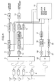
- Fig. 1 is a block diagram showing a configuration of a radio base station apparatus according to an embodiment of the present invention
- Fig. 2 is a block diagram showing a configuration of a unit for calculation of correlation matrix
- the reference numeral 1 refers to an antenna apparatus, 2 to a coupler, 3 and 20 to radio frequency units (RF units), 4 and 21 to A/D converters (ADC), 6 to a receive beam (Rx beam) form unit, 7 and 22 to despreaders, 8 to a space-time demodulator, 9 to a despreader for probe signal, 10 and 19 to D/A converters (DAC), 11 to a Transmit calibrater (Tx calibrater), 12 to a channel combiner, 13 to a spreader, 14 to a space-time modulator, 15 to a spreader for probe signal, 16 to a unit for calculation of correlation matrix, 17 to a spreader for probe signal, 18 to a power control unit, 23 to a signal input line, 24 to a multiplex
- an antenna is installed on a high steel tower or a rooftop of a building, being separated from a main part (an RF unit, a baseband unit, a control unit, etc.) of a base station. Accordingly, it is necessary to draw cables several ten meters long, and thus, it is difficult to keep phase relation between signals of respective antenna systems in their transmission. Further, the RF unit constituting the base station amplifies signals by amplifiers, and it is difficult to amplify signals while uniformly maintaining the noise figure (NF) and amplitude of respective systems. Thus, it is necessary to provide the base station with a unit that compensates the level and phase in some way.
- NF noise figure
- control of array weight is performed based on the array weight estimated in the receiving system as uplink, and accordingly, the system requires a mechanism for compensating the level and phase deviations generated in the receiving system and the level and phase deviations generated in the transmission system.
- the control of array weight is performed individually for each user, and thus, in the case of a CDMA system, array control in a baseband is desirable. Thus, it is necessary to maintain amplitude relation and phase relation of signals generated from baseband signals when they are transmitted from an antenna.
- a radio base station apparatus as an object of the embodiments of the present invention employs the CDMA system as a radio communication system, and uses an array antenna so that it can reduce interference between channels and increase, channel capacity.
- the radio base station apparatus is constructed to include a receive calibration system (Rx calibration system) and a transmit calibration system (Tx calibration system).
- Rx calibration system receive calibration system
- Tx calibration system transmit calibration system
- One of these systems may be used in certain embodiments, which are included in the scope of the present invention.
- both the Rx calibration system and Tx calibration system are required.
- a radio base station apparatus comprises: an antenna apparatus 1 consisting of a plurality of antenna elements 1; couplers 2 respectively provided in the neighborhoods of terminals of the antenna elements on the side of the base station apparatus; an RF unit 3 that converts a received signal to a baseband signal, converts a transmission signal to a radio frequency, and performs power control; an A/D converter 4 that converts the received baseband signal to a digital signal; an Rx beam form unit 6 that multiplies the digitized received signal by pre-set weight; a despreader 7 that despreads this signal; a time-space demodulator 8 that demodulates the despread signal to obtain user data; a despreader 9 for probe signal, that despreds the output signal of the A/D converter 4; a time-space modulator 14 that modulates user data; a spreader 13 that spreads this user data; a channel combiner 12 that performs channel combining with respect to signals from the spreader 13;
- a signal line shown as a heavy line indicates that, in fact, there exist signal lines corresponds to the number of the antenna elements in the antenna apparatus 1. Further, with respect to a component having input and output connected to a signal line of a heavy line, it means, in fact, that there exist a plurality of such components corresponding to the number of the antenna elements in the antenna apparatus 1.
- the added probe signal should be controlled in its power.
- Phase relation of each pair of the antennas can be obtained by calculating the correlation with respect to the result of despreading the probe signal. When the correlation shows a specific relation, it is assured that the received signals also have a specific relation, and each deviation of level and phase can be measured.
- the base station apparatus possessing the array antenna having a plurality of antenna elements comprises: the unit that adds the probe signal to each of received signals received by the antenna elements of the mentioned array antenna; the probe signal despreading unit that despreads the mentioned probe signal added to the received signals; the calibration calculating unit that calculates calibration required for calibrating phase and amplitude of each received signal based on the signals from the mentioned despreading unit; and a unit for calibrating phase and amplitude of the mentioned each received signal based on the calibration from the mentioned calibration calculating unit.
- signals received by the antenna apparatus 1 are mixed by the couplers 2 with the probe signal separately generated within the base station.
- the couplers corresponds to the antenna elements, and the probe signal to be mixed is branched and applied to each antenna element.
- the probe signal is supplied to the couplers 2 through one supply line.
- Complex amplitude of the probe signal supplied to each antenna element is decided by the physical relation between the couplers 2 and the signal supply line.
- the level and phase relation of the probe signal to be supplied can be known. In an actual field, based on those known data, it is possible to detect the level and phase deviations of the signal, which are generated since the signal passes through the RF unit 20 and the cable between the couplers 2 and the RF unit 20.
- the data that becomes source of the probe signal is a specific signal such as an all-0 signal, and produced by the unit for calculation of correlation matrix 16.
- the produced data is spread by the spreader 17 for probe signal.
- the power of the probe signal must be sufficiently small in comparison with other communication signals. This is because, when the power of the probe signal is large, interference by the probe signal largely affects other communication, and reduces the channel capacity. By this reason, the power control unit 18 keeps the power of the probe signal at the necessity minimum.
- the signal subjected to the power control is converted to an analog signal by the D/A converter 19.
- the converted probe signal is subject to frequency conversion and power conditioning, inputted to the couplers 2 through the supply line, and added to the received signals from the antenna apparatus 1.
- peak detection is required for detecting a phase of the spread code of the received signal.
- Methods of realizing it includes a method in which a signal received by an omni-antenna is used for the peak detection, and a method in which a signal received by one antenna of array antenna is used for the peak detection.
- the peak detection does not work well since the array gain can not be obtained owing to large interference power when, for example, the number of connected channels increases.
- effective is a method of improving a signal-to-interference-power ratio by employing beam forming with fixed weight to convert signals received through respective antenna elements (element space) to a group of independent beams (beam space).
- beam shapes are variable in accordance with time selectivity or space selectivity of, for example, traffic or topography, so as to improve peak detection sensitivity.
- the beam form unit for conversion to the beam space operates in the baseband.
- an array response vector adapted for a specific signal is not obtained, but a given directivity response pattern is realized by the beam form unit.
- a mechanism for compensating the level and phase deviations is required.
- the received signals which are received through a plurality of antenna elements of the antenna apparatus 1 and added with the probe signal, are subjected to frequency conversion in the RF unit 3, converted to baseband signals for respective antenna elements, and further converted to digital signals by the A/D converter 4.
- the signals converted to the digital signals by the A/D converter 4 are multiplied with semi-fixed array weight (array response vector) in the beam form unit 6 to be replaced by the beam space having a main beam in a specific direction of the antenna apparatus 1.
- semi-fixed array weight array response vector
- x is a signal vector in the beam space
- r is a signal vector in the element space
- C indicates calibration operation in the element space
- W indicates the conversion operation from the element space to the beam space.
- the matrices W and C are expressed unitedly by their product Q . This operation expresses the calibration and array weight operation according to the present invention.
- the beam form unit 6 in Fig. 6 multiplies the received signals by the matrix Q in response to a control signal from the blow-mentioned unit for calculation of correlation matrix 16, so as to perform unified operation including the beam forming and calibration of each element.
- the signals can be obtained from the beam form unit such that a signal from a specific direction (within the formed beam) is outputted as a larger value.
- the above-mentioned received signal calibration unit and the beam form unit for the array antenna are put together into one unit in the above-mentioned radio base station apparatus.
- the despreader 7 performs peak detection, and performs despreading operation based on the obtained path phase.
- the desired wave signals that come to have the space selectivity by the conversion to the beam space are improved in the signal-to-interference-power ratio, and become easy to perform the peak detection.
- the signals subjected to the despreading by the despreader 7 are returned to a user signal by the space-time demodulator 8 as a decoding unit.
- the user signal demodulated by the decoding by the space-time demodulator 8 is one that is obtained by combining the signals spread in the space and time directions with suitable weight to obtain diversity effect.
- Calibration information used in the above-mentioned beam form unit 6 can be obtained by the procedure described in the following.
- the signals that have been converted to the digital signals by the A/D converter 4 still have the level and phase deviations generated in each antenna element.
- the despreader 9 extracts these level and phase deviations and performs despreading operation on the probe signal included in the signals.
- the signals extracted from the despreader 9 by this operation are the probe signals applied to the terminals of respective antenna elements, added with the level and phase deviations generated in the RF unit 3 and the cables connecting the couplers 2 and the RF unit 3.
- the output signals of the probe signal despreader 9 are applied to the unit 16 for calculation of correlation matrix, to be used for preparing a correlation matrix for extracting level and phase relations.
- the unit 16 for calculation of correlation matrix obtains the correlation matrix based on the signals from the probe signal despreader 9.
- the obtained correlation matrix is the sum of a signal subspace and an interference subspace.
- the interference subspace becomes an error factor when other communications have space selectivity, and it is desirable to delete the interference subspace.
- the interference subspace can be obtained by performing spread intentionally using a spreading code that has not been used and by obtaining a similar correlation matrix based on the result of spreading. As shown in Eq. 2, the mentioned interference subspace can be obtained as a signal subspace A by subtracting the correlation matrix I that is obtained by performing despread intentionally using the nonuse spreading code, from a correlation matrix S that is obtained by using a spreading code adapted for the probe signal.
- Element space signature is obtained as the information obtained by calculating an eigen vector having the maximum eigen value from the obtained signal subspace A .
- This information indicates in which level and phase relation the signal applied in the element space is recived.
- the obtained information should be a value (target) predetermined by the topology of the antenna and the coupling relation of the system to which the probe signal is applied.
- the discrepancy between the measured value and the target becomes the calibration.
- the correlation matrix (target) that should be obtained in advance, can be used measurement obtained when the array pattern is adjusted to desired characteristics in a special measurement environment such as an anechoic chamber. By using this measurement as the target to obtain the calibration matrix C, it is possible to reproduce the desired array pattern even in an actual environment.
- Eq. 3 is a matrix indicating the probe signal subspace A measured in advance in a laboratory etc. when the level deviation and the phase deviation owing to the cable and the RF unit do not exit or are calibrated.
- the eigen vector ⁇ with the maximum eigen value can be obtained from the matrix A .
- Eq. 4 shows that ⁇ is an eigen vector of the matrix A .
- the operation eig in Fig. 4 means a function for extracting the eigen vector having the maximum eigen value.
- a signal subspace B measured in the actual environment is shown in Eq. 5.
- the eigen vector having the maximum eigen value can be obtained by the similar calculation.
- Eq. 6 shows the eigen vector ⁇ of the matrix B.
- the calibration matrix of the element space can be obtained by Eq. 7.
- the array control method shown in Fig. 1 can perform the conversion from the element space to the beam space and the calibration of the level and phase deviations in the element space, at the same time.
- the probe signal applied at the terminals of the antenna does not pass through the propagation path and accordingly is not affected by fading and the information of the probe signal is known. Owing to this, the despreading operation can be performed easily. As another important point, the generation and reception of the probe signal is performed in the same or adjacent apparatuses. Owing to this, it is possible to commonly use a local oscillator used for frequency conversion and timing generation in the RF unit.
- the present embodiment of the invention has the above-described configuration, it is possible to easily realize in-phase addition in a very long time without generating a frequency error and timing error. Further, variations of the phase and amplitude generated in the cable and the RF unit are very slow in comparison with the chip rate of the received signals, and it does not practically become problem to spend a long measuring time for estimating the correlation matrix. Accordingly, by increasing the spreading rate, effect of the probe signal on the other communications can be made very small. Signal strength of the probe signal can be known by the diagonal elements of the signal subspace. By controlling the power control unit 18 such that the diagonal elements give sufficient signal strength although not larger than the necessary, the effect of the probe signal on the other communications can be made very small. Further, in the above-described embodiment of the present invention, the level and phase deviations of each system are calibrated in the baseband unit. This can decrease calibration operation and production costs.
- Fig. 2 shows circuit structure of the unit 16 for calculation of correlation matrix for the case that the calibration matrix is generated by the time sharing processing.
- the unit 16 for calculation of correlation matrix of this example comprises a multiplexer 24, a conjugate calculator 25, a plurality of delay devices 26, a plurality of multipliers 27, and a plurality of memories 28.
- signals inputted to signal input lines 23 are signals from the respective antenna elements, signals from the despreader 9 for probe signal, shown in Fig. 1, the probe signals applied to the terminals of the respective antenna elements, and the level and phase deviations applied in the RF unit and in the cables between the couplers 2 and the RF unit 3.
- the multiplexer 24 has a function of timesharing six input signals one by one.
- the signals outputted serially in time sharing from the multiplexer 24 are inputted into the conjugate calculator 25 and into the multipliers 27 that are connected to the output sides of the conjugate calculator 25 and the serially-connected delay devices 26.
- the delay devices 26 operate synchronously with the multiplexer 24, and accordingly the multipliers 27 performs calculation of correlation between the signals delayed by the delay devices 26 and the just-inputted signal.
- the results of this operation are accumulated in the memories 28.
- the correlation matrix is accumulated in the memories 28.
- This information accumulated in the memories 28 is delivered to the beam form unit 6 of Fig. 1, to be subjected to the weight calibration processing in the baseband according to the present invention. Further, if necessary, contents accumulated in the memories 28 can be used after further averaging processing. In that case, precision of the calibration can be improved.
- the Tx calibration system should add the probe signal to transmission signals in the baseband unit, and extract the signals from the terminals of the antennas. It is necessary to perform investigation on one antenna system (element) out of a plurality of antenna terminals. This investigation can be performed such that: (1) one of signals to a plurality of antenna systems is selected in the baseband, and the probe signal is applied to that signal; (2) signals extracted from the antenna terminals are subjected to despreading, to investigate response of each antenna system by time sharing; and (3) correlation is calculated on the result of despreading. When the correlation indicates a specific relation, it is assured that received signals are also in the specific relation, and each of the level and phase deviations can be measured.
- the RF unit that converts the mentioned received signals to baseband signals has a function of converting the signals, which have been subjected to the D/A conversion, to radio frequencies so as to input them into the respective antenna elements;
- the mentioned couplers have a function of extracting a part of transmission signal inputted into each of antenna elements; and the mentioned probe signal RF unit has a function of converting the signals from the mentioned couplers to baseband signals.
- the present embodiment comprises: the spreader for Tx probe signal, which spreads a specific code series using a specific spread code; the Tx signal calibrater that calibrates transmission signals generated in the modulator by the signals from the mentioned unit for calculation of correlation matrix; the Tx signal combiner that adds the output signal of the mentioned spreader for Tx probe signal to only a signal to be transmitted from one antenna element out of the signals generated by the mentioned calibrater, so as to generate a transmission signal added with probe: the D/A converter that converts the output of the mentioned Tx signal combiner from a digital signal to an analog signal and inputs the converted signal to the mentioned RF unit that converts received signals to baseband signals; the A/D converter for probe signal that performs conversion from an analog signal to a digital signal on the signals that are received from the mentioned couplers and have been converted to the baseband signals in the mentioned probe signal RF unit; and the despreader for Tx probe signal that despreads the output of the mentioned A/D converter for probe signal using the spread code of the Tx probe
- the mentioned unit for calculation of correlation matrix is provided with the Tx signal calibration system that obtains correlation of Tx probe signals between each pair of the antennas based on the output of the despreader for Tx probe signal and calculates quantity of phase rotation and quantity of amplitude calibration required for realizing a specific relation between the eigen vector having the maximum eigen value decided from the obtained correlation matrix and a predetermined vector, so as to control the calibration by the mentioned calibrater.
- prepared user data is subjected to space modulation by the space modulator 14.
- the space modulator means a modulation circuit that additionally contains operations for giving a suitable phase and amplitude to each antenna element in order to form a beam, in comparison with an ordinary modulation circuit.
- Information of a user is spread by the spreader 13 using a spread code that is different for each user.
- the spread data is added in the channel combiner 12 to be aggregated to information corresponding to the number of the antenna elements.
- the signal aggregated to the number of the antenna elements is subject to pre-calibration in the calibrater 11 based on the signal from the unit 16 for calculation of correlation matrix, with respect to the level deviation and phase rotation that are to be generated in the cables, amplifiers, etc.
- the calibrated signal is converted to an analog signal in the D/A converter 10, subjected to up-conversion and power amplification in the RF unit 3, and inputted to each antenna element, to be transmitted from the antenna apparatus 2.
- the method of obtaining the calibration vector for transmission signals in the unit 16 for calculation of correlation matrix is generally similar to the above-described case of the receiving system.
- a reference signal for example, a signal of all-0
- the spread signal is added to a signal line corresponding to each antenna element, between the calibrater 11 and the D/A converter 10.
- the signal is not distributed to all the antenna elements at the same time but added to each signal line one after another by time-sharing. By this, a receiving side can clearly distinguish an antenna element that transmitted the received signal.
- the Tx probe signal is mixed to a specific antenna by time-sharing.
- the Tx probe signal may be added at the same time, by changing the spread code for the Tx probe signal for each antenna element. Namely, it is simply that signals applied to the respective antenna elements are spread by respective spread codes. In this case, however, interference given by the measurement system increases, being multiplied by the number of the antenna elements.
- the coupler 2 extracts a part of the signal transmitted.
- the extracted signal is down-converted by the RF unit 20.
- the signal from the RF unit 20 is converted to a digital signal by the A/D converter 21, and the converted signal is despread by the despreader 22 to be inputted to the unit 16 for calculation of correlation matrix.
- the unit 16 for calculation of correlation matrix calculates the calibration matrix C by the method shown by the above-described Eqs. 1 ⁇ 7.
- the calculated calibration matrix C is inputted to the calibrater 11 for calibration of the transmission signal.
- the above-described embodiment of the present invention can also calibrate the amplitude and phase deviations owing to the cables, amplifiers, etc. in the transmission system.
- the mentioned Rx signal calibration system and Tx signal calibration system use the same local oscillator as an oscillation source to perform up-conversion and down-conversion, and to perform timing generation.
- the radio base station apparatus has been described as one in which the RF units 3 and 20 of Fig. 1 use the same local oscillator.
- these RF units 3 and 20 may use different local oscillators, and, in that case, the AFC (Auto Frequency Control) function may be used to obtain spread gain.
- AFC Automatic Frequency Control
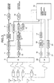
- Fig. 3 is a block diagram showing a configuration of a radio base station apparatus according to another embodiment of the present invention, and it will be described in the following.
- the reference numeral 5 refers to a calibrater and the other symbols are same as in Fig. 1.
- the embodiment shown in Fig. 3 is different from the embodiment shown in Fig. 1 in that the beam form unit 6 for the Rx calibration system is separated into a beam form unit 6 and the calibrater 5, that the point for extracting the probe signal is an output terminal of the calibrater 5, and that the signal obtained by spreading the reference signal of the Tx calibration system is inputted to an output terminal of the spreader 13.
- the results of a series of operations on the signals are not changed, and the results similar to Fig. 1 are obtained.
- the probe signal is spread by the spreaders 15 and 17.
- the other signals are spread, it is not necessary to spread the probe signal in order to separate it from the other communications.
- the probe signal can be considered as a signal spread by a signal of all-0.
- the above-described embodiment of the present invention can dispense with the spreaders 15 and 17, which simplifies the apparatus.
- a sine wave may be used as the probe signal.
- Figs. 4 ⁇ 6 are views for explaining examples of configuration of an antenna apparatus according to embodiments of the present invention, and, now, structure of the antenna will be described in the following.
- the reference numeral 29 refers to an antenna element, 30 to a signal line, 31 to a probe signal line, 32 to a radiating element, 33, 34 and 37 to probe signal elements, and 38 ⁇ 40 to array antennas.
- the above-described embodiments of the present invention have been described as ones in which the couplers are provided in the subsequent stage of the antenna terminals. However, when the target is to be obtained in a test in an anechoic chamber or the like, it is convenient that a coupler is contained in an antenna itself.
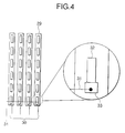
- the antenna apparatus of the embodiment shown in Fig. 4 is an array antenna that comprises a plurality of antenna elements 29.
- the signal lines 30 connected to the terminals of the antenna elements 29 are connected to the RF unit 3, and the probe signal line 31 is connected to the RF unit 20.
- the coupler 2 comprises a probe signal element 33 consisting of a piece of metal that is in weak conjunction with a radiating element 32 connected to a signal line for each antenna element 29.
- the signal line 31 is connected to this probe signal element 33. It is sufficient that the terminal of the antenna element 29 to which the signal line 30 is connected and the terminal of the probe signal element 33 to which the probe signal line 31 is connected are in weak conjunction with each other at isolation of about 20 dB.
- the antenna apparatus shown in Fig. 4 according to the embodiment of the present invention can be constructed such that the antenna apparatus 1 and the couplers 2 are unified.
- the convenient antenna apparatus can be constructed.
- Fig. 5 shows structure of an antenna apparatus according to another embodiment of the present invention.
- This antenna apparatus is an array antenna similar to one shown in Fig. 4.
- a part constituting a coupler 2 is constructed such that a probe signal element 34 as an antenna element for radiation of the probe signal is provided in the neighborhood of a plurality of antenna elements 29 in common. Even when the coupling element is arranged in space as described, can be obtained an effect similar to the case described referring to Fig. 4 in which input and output of signal is carried out through the weak conjunction with the radiating element of the antenna.
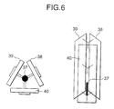
- Fig. 6 shows a configuration of an antenna apparatus according to still another embodiment of the present invention.
- This antenna apparatus is an example of an antenna apparatus constructed such that a plurality of array antennas described referring to Fig. 5 and a radiating element for probe.
- the antenna apparatus shown in Fig. 6 is constructed such that the array antennas 38 ⁇ 40 are arranged in an equilateral triangle to form a triangular prism and a probe signal element 37 is provided in the central portion of the triangular prism.
- each array antenna corresponding to a side of the triangle comprises a bottom board (reflecting element) 38' ⁇ 40' and a radiating element 38'' ⁇ 40'' arranged on the surface of the bottom board.
- the probe signal element 37 is arranged in the center of the cavity enclosed by the array antennas 38 ⁇ 40.
- the antenna apparatus described referring to Fig. 6 is constructed such that the array antennas are arranged into a triangular prism.
- a plurality of array antennas or antenna elements may be arranged in a shape of a polygon, or antenna elements may be arranged into a cylinder. In that case, when the probe signal element exists inside the polygon or cylinder made by the array antennas, similar effect can be obtained.
- a radio base station apparatus in which amplitude and phase deviations of signals generated to an array antenna owing to cables connected to the base station apparatus and amplifiers within the base station apparatus can be calibrated in the baseband.
- an antenna apparatus that is suitable for use in combination with this base station can be provided.
Abstract
Description


Claims (19)
- A radio base station apparatus provided with an array antenna having a plurality of antenna elements, comprising:a probe signal adding unit which adds a probe signal to each of receive signals received by said plurality of antenna elements;a probe signal extracting unit which extracts the probe signal from said receive signals added with the probe signal;a phase calibration calculation unit which calculates phase calibration required for calibrating a phase of each receive signal based on the probe signal extracted by said probe signal extracting unit; anda phase calibration unit for calibrating said phase of the each receive signal based on the phase calibration from said phase calibration calculation unit.
- The radio base station apparatus according to Claim 1, wherein:said probe signal extracting unit comprises a despreading unit which despreads the receive signals added with said probe signal to extract said probe signal.
- The radio base station apparatus according to Claim 2, wherein:said probe signal adding unit comprises:a probe signal generating unit which spreads probe data with a predetermined spread code to generate the probe signal;a conversion unit which converts said probe signal to a radio signal; anda coupling unit which couples the probe signal converted to said radio signal and said receive signals; andsaid despreading unit performs despreading on signals outputted from said coupling unit, using the same spread code used in said probe signal generating unit, in order to extract the probe data; andsaid phase calibration calculation unit calculates the phase calibration required for calibrating the phase of each receive signal based on the probe data extracted by said despreading unit.
- The radio base station apparatus according to Claim 3, wherein:said phase calibration calculation unit compares the probe data extracted by said despreading unit and the original probe data inputted to said probe signal generating unit, calculates quantity of distortion given to the probe data extracted by said despreading unit, and calculates the calibration that cancels said quantity of distortion; andsaid phase calibration unit calibrates the receive signals based on said calibration.
- The radio base station apparatus according to Claim 3, further comprising:a power control unit that controls power of the probe signal generated by said probe signal generating unit and outputs the probe signal that has been subjected to the power control to said conversion unit.
- The radio base station apparatus according to Claim 2, wherein:a spreading rate of said probe signal is larger than spreading rates of other communication signals.
- The radio base station apparatus according to Claim 1, wherein:said probe signal is a sine wave.
- The radio base station apparatus according to Claim 1, further comprising:an amplitude calibration calculation unit which calculates amplitude calibration required for calibrating amplitude of each receive signal based on the probe signal extracted by said probe signal extracting unit; andan amplitude calibration unit which calibrates an amplitude of said each receive signal based on the amplitude calibration from said amplitude calibration calculation unit.
- The radio base station apparatus according to Claim 1, further comprising:a transmit signal generating unit which generates a transmit signal;a transmit probe signal adding unit which adds a transmit probe signal to said transmit signal when said transmit signal generated by said transmit signal generating unit is supplied to said plurality of antenna elements;a transmit probe signal extracting unit which extracts said transmit probe signal from the transmit signal that is added with the transmit probe signal by said transmit probe signal adding unit;a transmit phase calibration calculation unit which calculates transmit phase calibration required for calibration of a phase of said transmit signal based on the transmit probe signal extracted by said transmit probe signal extracting unit; anda transmit phase calibration unit which calibrates the phase of said transmit signal based on the transmit phase calibration from said transmit phase calibration calculation unit.
- A radio base station apparatus provided with an array antenna having a plurality of antenna elements, wherein:a receive signal calibration system of said radio base station apparatus comprises:a receive probe signal spreading unit which spreads a specific code series with a specific spread code;a power control unit which performs power control on an output signal of said receive probe signal spreading unit;a D/A converting unit for the receive probe signal, for converting an output signal of said power control unit from a digital signal to an analog signal;a probe signal RF unit which converts an output signal of said D/A converting unit to a radio frequency and performs power control on said radio frequency;a coupling unit which adds said probe signal to receive signals received respectively by said plurality of antenna elements, so as to generate receive signals added with probe;an RF unit which converts the receive signals added with probe, which are generated in said coupling unit, to baseband signals;an A/D converting unit which converts the baseband signals generated in said RF unit to digital signals;a receive probe signal despreading unit which outputs results of despreading the signals subjected to said A/D conversion with a spread code used for the probe signal, and which outputs results of despreading said signals intentionally with a spread code that has not been used;a correlation matrix calculation unit that obtains correlation of receive probe signals between each pair of antenna elements from the output of said receive probe signal despreading unit, calculates a signal subspace from an obtained correlation matrix, and calculates phase rotation and amplitude calibration required for an eigen vector having a maximum eigen value of the signal subspace and a predetermined vector to have a specific relation with each other; anda receive signal calibration unit which performs calibration of the output signals of the A/D converting unit, with said output signals being converted from said baseband signals by the A/D converting unit, and with said calibration corresponding to said phase rotation and said amplitude calibration calculated by said correlation matrix calculation unit; andsaid power control unit controls power of said probe signal inputted, such that the power becomes a necessity minimum required for said correlation matrix calculation unit to calculate the correlation matrix.
- The radio base station apparatus according to Claim 10, wherein:said RF unit has a function of converting the signal subjected to the D/A conversion to a radio frequency and of inputting the converted radio frequency to each antenna element;said coupling unit has a function of extracting a part of a transmit signal inputted to each antenna element; andsaid probe signal RF unit has a function of converting a signal from said coupling unit to a baseband signal.
- The radio base station apparatus according to Claim 11, wherein:a transmit signal calibration system of said radio base station apparatus comprises:a transmit probe signal spreading unit which spreads a specific code series with a specific spread code;a transmit signal calibration unit which calibrates a transmit signal generated in a modulation unit, using signals from said correlation matrix calculation unit;a transmit signal combining unit which selectively adds an output signal of said transmit probe signal spreading unit, only to a signal to be transmitted from one antenna element out of transmit signals generated in said calibration unit, so as to generate transmit signals added with probe;a D/A converting unit which converts an output of said transmit signal combining unit from digital signals to analog signals and for inputting said analog signals to said RF unit that converts the receive signals to the baseband signals;an A/D converting unit for probe signal, for converting an analog signal to a digital signal, said analog signal being the baseband signal converted in said probe signal RF unit from the signal from said coupling unit; anda transmit probe signal despreading unit which despreads an output of said A/D converting unit for probe signal with the spread code of the transmit probe signal, and for inputting the despread output to said correlation matrix calculation unit; andsaid correlation matrix calculation unit obtains correlation of transmit probe signals between each pair of antenna elements from the output of the transmit probe signal despreading unit, and calculates phase rotation and amplitude calibration required for an eigen vector having a maximum eigen value of an obtained correlation matrix and a predetermined vector to have a specific relation with each other, so as to control calibration by said calibration unit.
- The radio base station apparatus according to Claim 12, wherein:said receive signal calibration system and said transmit signal calibration system use a same local oscillator as an oscillation source to perform up-conversion and down-conversion respectively, and use a same local oscillator as an oscillation source to perform timing generation.
- The radio base station apparatus according to Claim 12, wherein:said transmit probe signal is not added selectively to a specific antenna element, but a signal using a different spread code for each antenna element is added to a signal of each antenna element.
- The radio base station apparatus according to Claim 12, wherein:said receive signal calibration unit and a beam form unit for the array antenna are formed within a same unit, and said transmit signal calibration unit and a beam form unit for the array antenna are formed within a same unit.
- The radio base station apparatus according to Claim 13, wherein:said transmit probe signal is not added selectively to a specific antenna element, but a signal using a different spread code for each antenna element is added to a signal of each antenna element.
- An array antenna that comprises a plurality of antenna elements and is used for a radio base station apparatus, said array antenna further comprising:a plurality of input-output terminals corresponding to the plurality of antenna elements;auxiliary antenna elements, each of which is in weak conjunction with a part of a radiating element constituting each antenna element; andinput-output terminals for probe signal connected respectively to said auxiliary antenna elements.
- The array antenna according to Claim 17, wherein:instead of said auxiliary antenna element, each of which is in weak conjunction with a part of the radiating element constituting each antenna element, said array antenna comprises an auxiliary antenna element arranged in a position physically separated from said plurality of antenna elements, and said input-output terminals for probe signal are connected to said auxiliary antenna element.
- The array antenna according to Claim 17, wherein:said auxiliary antenna elements are provided within a polygonal prism or a cylinder formed by said antenna elements.
Applications Claiming Priority (2)
| Application Number | Priority Date | Filing Date | Title |
|---|---|---|---|
| JP26040799A JP4303373B2 (en) | 1999-09-14 | 1999-09-14 | Wireless base station equipment |
| JP26040799 | 1999-09-14 |
Publications (3)
| Publication Number | Publication Date |
|---|---|
| EP1085684A2 true EP1085684A2 (en) | 2001-03-21 |
| EP1085684A3 EP1085684A3 (en) | 2003-05-28 |
| EP1085684B1 EP1085684B1 (en) | 2006-06-14 |
Family
ID=17347503
Family Applications (1)
| Application Number | Title | Priority Date | Filing Date |
|---|---|---|---|
| EP00120040A Expired - Lifetime EP1085684B1 (en) | 1999-09-14 | 2000-09-14 | Radio base station with array antenna and transmission calibration |
Country Status (4)
| Country | Link |
|---|---|
| US (3) | US6647276B1 (en) |
| EP (1) | EP1085684B1 (en) |
| JP (1) | JP4303373B2 (en) |
| DE (1) | DE60028677T2 (en) |
Cited By (30)
| Publication number | Priority date | Publication date | Assignee | Title |
|---|---|---|---|---|
| EP1416655A2 (en) * | 2002-10-30 | 2004-05-06 | Nec Corporation | Array antenna transceiver and calibrating method of transmission route used for the same |
| EP1496567A1 (en) * | 2003-07-10 | 2005-01-12 | Siemens Aktiengesellschaft | Arrangement for calibrating transmission and/or reception of signals in a radio communications system |
| EP1585231A1 (en) * | 2002-12-25 | 2005-10-12 | Da Tang Mobile Communications Equipment Co., Ltd. | A method for calibrating smart antenna array systems in real time |
| EP1615291A1 (en) * | 2003-04-15 | 2006-01-11 | Matsushita Electric Industrial Co., Ltd. | Array antenna transmitter/receiver |
| CN1315269C (en) * | 2003-03-27 | 2007-05-09 | 三洋电机株式会社 | Transmitting method and wireless apparatus thereby |
| WO2008088859A2 (en) * | 2007-01-18 | 2008-07-24 | Mobileaccess Networks Ltd. | Hybrid passive active broadband antenna for a distributed antenna system |
| GB2467771A (en) * | 2009-02-13 | 2010-08-18 | Socowave Technologies Ltd | Digital beam-forming by a network element located between an antenna array and a base station |
| EP2271003A1 (en) * | 2004-05-18 | 2011-01-05 | ATC Technologies, LLC | Satellite communications systems and methods using radiotelephone location-based beamforming |
| US8111959B2 (en) | 2008-07-30 | 2012-02-07 | Corning Mobileaccess Ltd | Method and system for coupling multimode optical fiber to an optical detector |
| US8175649B2 (en) | 2008-06-20 | 2012-05-08 | Corning Mobileaccess Ltd | Method and system for real time control of an active antenna over a distributed antenna system |
| US8184681B2 (en) | 2006-01-11 | 2012-05-22 | Corning Mobileaccess Ltd | Apparatus and method for frequency shifting of a wireless signal and systems using frequency shifting |
| US8195224B2 (en) | 2008-05-13 | 2012-06-05 | Corning Mobileaccess Ltd | Multiple data services over a distributed antenna system |
| EP2372930A3 (en) * | 2010-03-31 | 2012-10-10 | Ubidyne, Inc. | Active antenna array and method for calibration of the active antenna array |
| US8325693B2 (en) | 2004-05-06 | 2012-12-04 | Corning Mobileaccess Ltd | System and method for carrying a wireless based signal over wiring |
| US8340612B2 (en) | 2010-03-31 | 2012-12-25 | Ubidyne, Inc. | Active antenna array and method for calibration of the active antenna array |
| US8441966B2 (en) | 2010-03-31 | 2013-05-14 | Ubidyne Inc. | Active antenna array and method for calibration of receive paths in said array |
| US8594133B2 (en) | 2007-10-22 | 2013-11-26 | Corning Mobileaccess Ltd. | Communication system using low bandwidth wires |
| US8873585B2 (en) | 2006-12-19 | 2014-10-28 | Corning Optical Communications Wireless Ltd | Distributed antenna system for MIMO technologies |
| US8897215B2 (en) | 2009-02-08 | 2014-11-25 | Corning Optical Communications Wireless Ltd | Communication system using cables carrying ethernet signals |
| CN104409817A (en) * | 2014-12-06 | 2015-03-11 | 河南蓝海通信技术有限公司 | Combining device |
| US9026036B2 (en) | 2005-02-28 | 2015-05-05 | Corning Optical Communications Wireless Ltd. | Method and system for integrating an RF module into a digital network access point |
| US9184960B1 (en) | 2014-09-25 | 2015-11-10 | Corning Optical Communications Wireless Ltd | Frequency shifting a communications signal(s) in a multi-frequency distributed antenna system (DAS) to avoid or reduce frequency interference |
| US9258052B2 (en) | 2012-03-30 | 2016-02-09 | Corning Optical Communications LLC | Reducing location-dependent interference in distributed antenna systems operating in multiple-input, multiple-output (MIMO) configuration, and related components, systems, and methods |
| US9276656B2 (en) | 2007-02-19 | 2016-03-01 | Corning Optical Communications Wireless Ltd | Method and system for improving uplink performance |
| US9338823B2 (en) | 2012-03-23 | 2016-05-10 | Corning Optical Communications Wireless Ltd | Radio-frequency integrated circuit (RFIC) chip(s) for providing distributed antenna system functionalities, and related components, systems, and methods |
| US9525472B2 (en) | 2014-07-30 | 2016-12-20 | Corning Incorporated | Reducing location-dependent destructive interference in distributed antenna systems (DASS) operating in multiple-input, multiple-output (MIMO) configuration, and related components, systems, and methods |
| US9531452B2 (en) | 2012-11-29 | 2016-12-27 | Corning Optical Communications LLC | Hybrid intra-cell / inter-cell remote unit antenna bonding in multiple-input, multiple-output (MIMO) distributed antenna systems (DASs) |
| US9729267B2 (en) | 2014-12-11 | 2017-08-08 | Corning Optical Communications Wireless Ltd | Multiplexing two separate optical links with the same wavelength using asymmetric combining and splitting |
| CN109792303A (en) * | 2016-10-04 | 2019-05-21 | 瑞典爱立信有限公司 | Determine the method and radio network node of the total radiant power from mutiple antennas |
| US11130958B2 (en) | 2007-04-18 | 2021-09-28 | Performance Plants, Inc. | Plants having increased tolerance to heat stress |
Families Citing this family (74)
| Publication number | Priority date | Publication date | Assignee | Title |
|---|---|---|---|---|
| JP4303373B2 (en) * | 1999-09-14 | 2009-07-29 | 株式会社日立コミュニケーションテクノロジー | Wireless base station equipment |
| DE60043909D1 (en) * | 1999-12-15 | 2010-04-08 | Nippon Telegraph & Telephone | Adaptive array antenna transceiver |
| JP4392109B2 (en) * | 2000-05-12 | 2009-12-24 | パナソニック株式会社 | Direction of arrival estimation device |
| US6920192B1 (en) * | 2000-08-03 | 2005-07-19 | Lucent Technologies Inc. | Adaptive antenna array methods and apparatus for use in a multi-access wireless communication system |
| US7031754B2 (en) * | 2001-06-11 | 2006-04-18 | Kathrein-Werke Kg | Shapable antenna beams for cellular networks |
| JP3651430B2 (en) * | 2001-09-17 | 2005-05-25 | 日本電気株式会社 | Array antenna calibration apparatus and calibration method |
| US7039135B2 (en) * | 2001-10-11 | 2006-05-02 | D.S.P.C. Technologies Ltd. | Interference reduction using low complexity antenna array |
| JP4086574B2 (en) | 2002-04-12 | 2008-05-14 | 松下電器産業株式会社 | Path search circuit, radio reception device, and radio transmission device |
| JP2003309513A (en) * | 2002-04-16 | 2003-10-31 | Matsushita Electric Ind Co Ltd | Adaptive array antenna reception apparatus and antenna array calibration method |
| JP3895228B2 (en) * | 2002-05-07 | 2007-03-22 | 松下電器産業株式会社 | Wireless communication apparatus and direction of arrival estimation method |
| DE10237822B3 (en) * | 2002-08-19 | 2004-07-22 | Kathrein-Werke Kg | Calibration device for a switchable antenna array and an associated operating method |
| DE10237823B4 (en) * | 2002-08-19 | 2004-08-26 | Kathrein-Werke Kg | Antenna array with a calibration device and method for operating such an antenna array |
| JP3440095B1 (en) * | 2002-08-23 | 2003-08-25 | 富士通株式会社 | Data transmission device and data transmission method |
| US7151951B2 (en) * | 2002-12-23 | 2006-12-19 | Telefonktiebolaget Lm Ericsson (Publ) | Using beamforming and closed loop transmit diversity in a multi-beam antenna system |
| JP2005064819A (en) * | 2003-08-11 | 2005-03-10 | Matsushita Electric Ind Co Ltd | Array antenna receiving device and method for calibrating received signal |
| KR100957354B1 (en) * | 2003-11-10 | 2010-05-12 | 삼성전자주식회사 | Apparatus and method for forward_link beam-forming in a smart antenna system |
| US7787829B1 (en) | 2003-12-23 | 2010-08-31 | Cypress Semiconductor Corporation | Method and apparatus for tuning a radio receiver with a radio transmitter |
| CN1879311B (en) * | 2003-12-31 | 2010-04-28 | 中兴通讯股份有限公司 | Adjustment device and method for array antenna transmitting link |
| JP4405331B2 (en) * | 2004-07-06 | 2010-01-27 | 富士通株式会社 | Wireless receiver, wireless transmitter, and calibration method |
| CN100541465C (en) * | 2004-09-07 | 2009-09-16 | 飞思卡尔半导体公司 | Be used to produce the device and the integrated circuit of a plurality of different strobe signal |
| CN100426897C (en) * | 2005-01-12 | 2008-10-15 | 华为技术有限公司 | Separated base station system and its networking method and baseband unit |
| JP4528208B2 (en) * | 2005-06-10 | 2010-08-18 | 富士通株式会社 | Array antenna calibration apparatus and calibration method |
| US7733287B2 (en) * | 2005-07-29 | 2010-06-08 | Sony Corporation | Systems and methods for high frequency parallel transmissions |
| JP4528236B2 (en) * | 2005-09-29 | 2010-08-18 | 株式会社日立製作所 | Radio base station apparatus and communication method |
| US7746922B2 (en) * | 2005-12-07 | 2010-06-29 | Cypress Semiconductor Corporation | Apparatus and method for frequency calibration between two radios |
| US7853216B1 (en) | 2005-12-22 | 2010-12-14 | Atheros Communications, Inc. | Multi-channel RX/TX calibration and local oscillator mismatch mitigation |
| US20090298509A1 (en) * | 2006-01-19 | 2009-12-03 | Matsushita Electric Industrial Co., Ltd. | Radio transmission device and radio transmission method |
| JP4774306B2 (en) * | 2006-02-02 | 2011-09-14 | 富士通株式会社 | Interference reduction receiving apparatus and method |
| CA2547649A1 (en) * | 2006-04-04 | 2007-10-04 | Tenxc Wireless Inc. | Method and apparatus for uplink coverage improvement |
| JP4355325B2 (en) * | 2006-04-25 | 2009-10-28 | 京セラ株式会社 | Communication apparatus and transmission calibration weight calculation method |
| US8478344B2 (en) * | 2006-06-21 | 2013-07-02 | Broadcom Corporation | Power recovery circuit based on partial standing waves |
| US20080129613A1 (en) * | 2006-12-05 | 2008-06-05 | Nokia Corporation | Calibration for re-configurable active antennas |
| US7764935B2 (en) * | 2006-12-21 | 2010-07-27 | Nokia Corporation | Phase and power calibration in active antennas |
| US8090044B2 (en) * | 2006-12-29 | 2012-01-03 | Broadcom Corporation | Multimode transceiver for use with multiple antennas and method for use therewith |
| US8064533B2 (en) * | 2006-12-29 | 2011-11-22 | Broadcom Corporation | Reconfigurable MIMO transceiver and method for use therewith |
| US8049662B2 (en) * | 2007-07-23 | 2011-11-01 | Aviation Communication&Surveillance Systems LLC | Systems and methods for antenna calibration |
| EP2183818A1 (en) | 2007-08-31 | 2010-05-12 | BAE Systems PLC | Antenna calibration |
| US8004456B2 (en) * | 2007-08-31 | 2011-08-23 | Bae Systems Plc | Antenna calibration |
| EP2183820A1 (en) * | 2007-08-31 | 2010-05-12 | BAE Systems PLC | Antenna calibration |
| DK2183817T3 (en) * | 2007-08-31 | 2017-11-27 | Bae Systems Plc | ANTENNA CALIBRATION |
| GB2454937A (en) * | 2007-11-23 | 2009-05-27 | Ubiquisys Ltd | Acquiring time references for a telecommunications basestation from a time server |
| JP2008172808A (en) * | 2008-01-29 | 2008-07-24 | Kyocera Corp | Signal processing module, wireless apparatus utilizing the same, and radio base station |
| US7970359B2 (en) * | 2008-07-29 | 2011-06-28 | Alvarion Ltd. | Delay diversity in antenna arrays |
| EP2192707A1 (en) * | 2008-11-26 | 2010-06-02 | Nokia Siemens Networks OY | Method of calibrating an active antenna and active antenna |
| US8761835B2 (en) * | 2009-06-08 | 2014-06-24 | Telefonaktiebolaget L M Ericsson (Publ) | Wireless communication node and a method related thereto |
| CN101958744B (en) * | 2009-07-13 | 2013-11-20 | 电信科学技术研究院 | Method and device for pre-calibrating frequency deviation |
| JP5768953B2 (en) * | 2010-08-02 | 2015-08-26 | 日本電気株式会社 | Communication satellite, calibration system, and array antenna calibration method |
| EP2789111A4 (en) * | 2011-12-06 | 2015-04-08 | Ericsson Telefon Ab L M | Doppler shift compensation apparatus and method |
| US20130260844A1 (en) * | 2012-03-28 | 2013-10-03 | Andrew Llc | Series-connected couplers for active antenna systems |
| US8767862B2 (en) | 2012-05-29 | 2014-07-01 | Magnolia Broadband Inc. | Beamformer phase optimization for a multi-layer MIMO system augmented by radio distribution network |
| US9154204B2 (en) | 2012-06-11 | 2015-10-06 | Magnolia Broadband Inc. | Implementing transmit RDN architectures in uplink MIMO systems |
| JP2014027653A (en) * | 2012-06-21 | 2014-02-06 | Samsung Electronics Co Ltd | Communication device, and directivity control method |
| US8797969B1 (en) | 2013-02-08 | 2014-08-05 | Magnolia Broadband Inc. | Implementing multi user multiple input multiple output (MU MIMO) base station using single-user (SU) MIMO co-located base stations |
| US9343808B2 (en) | 2013-02-08 | 2016-05-17 | Magnotod Llc | Multi-beam MIMO time division duplex base station using subset of radios |
| US9155110B2 (en) | 2013-03-27 | 2015-10-06 | Magnolia Broadband Inc. | System and method for co-located and co-channel Wi-Fi access points |
| US9100968B2 (en) | 2013-05-09 | 2015-08-04 | Magnolia Broadband Inc. | Method and system for digital cancellation scheme with multi-beam |
| WO2015002448A1 (en) * | 2013-07-02 | 2015-01-08 | Samsung Electronics Co., Ltd. | Apparatus and method for controlling orientation |
| JP2015012568A (en) * | 2013-07-02 | 2015-01-19 | 三星電子株式会社Samsung Electronics Co.,Ltd. | Device and method for directivity control |
| US9497781B2 (en) | 2013-08-13 | 2016-11-15 | Magnolia Broadband Inc. | System and method for co-located and co-channel Wi-Fi access points |
| US9172454B2 (en) * | 2013-11-01 | 2015-10-27 | Magnolia Broadband Inc. | Method and system for calibrating a transceiver array |
| US8891598B1 (en) | 2013-11-19 | 2014-11-18 | Magnolia Broadband Inc. | Transmitter and receiver calibration for obtaining the channel reciprocity for time division duplex MIMO systems |
| US8942134B1 (en) | 2013-11-20 | 2015-01-27 | Magnolia Broadband Inc. | System and method for selective registration in a multi-beam system |
| US9294177B2 (en) | 2013-11-26 | 2016-03-22 | Magnolia Broadband Inc. | System and method for transmit and receive antenna patterns calibration for time division duplex (TDD) systems |
| EP2884675A1 (en) * | 2013-12-12 | 2015-06-17 | Airbus Defence and Space Limited | Phase or amplitude compensation for beam-former |
| US9172446B2 (en) | 2014-03-19 | 2015-10-27 | Magnolia Broadband Inc. | Method and system for supporting sparse explicit sounding by implicit data |
| US9100154B1 (en) | 2014-03-19 | 2015-08-04 | Magnolia Broadband Inc. | Method and system for explicit AP-to-AP sounding in an 802.11 network |
| EP3142188B1 (en) * | 2014-06-06 | 2020-01-01 | Huawei Technologies Co., Ltd. | Array antenna calibration method, device and system |
| US10009124B2 (en) * | 2015-03-11 | 2018-06-26 | Telefonaktiebolaget Lm Ericsson (Publ) | Methods and apparatus for antenna calibration |
| CN105072568B (en) * | 2015-08-11 | 2018-10-26 | 武汉拓宝科技股份有限公司 | Multiple antennas wireless access and method for M2M |
| JP6955484B2 (en) * | 2015-09-10 | 2021-10-27 | ブルー ダニューブ システムズ, インク.Blue Danube Systems, Inc. | Active array calibration |
| WO2017203324A1 (en) * | 2016-05-24 | 2017-11-30 | Telefonaktiebolaget Lm Ericsson (Publ) | Method and apparatus for antenna array calibration using on-board receiver |
| US10263330B2 (en) * | 2016-05-26 | 2019-04-16 | Nokia Solutions And Networks Oy | Antenna elements and apparatus suitable for AAS calibration by selective couplerline and TRX RF subgroups |
| CN110518990B (en) * | 2019-08-19 | 2021-10-22 | 深圳创维数字技术有限公司 | Calibration method, system and computer readable storage medium for multi-antenna WiFi product |
| US11316656B1 (en) * | 2020-07-08 | 2022-04-26 | The Johns Hopkins University | Time transfer modem |
Citations (7)
| Publication number | Priority date | Publication date | Assignee | Title |
|---|---|---|---|---|
| US5546090A (en) * | 1991-12-12 | 1996-08-13 | Arraycomm, Inc. | Method and apparatus for calibrating antenna arrays |
| WO1997000543A1 (en) * | 1995-06-16 | 1997-01-03 | Watkins-Johnson Company | Method and apparatus for adaptive transmission beam forming in a wireless communication system |
| US5603098A (en) * | 1995-04-21 | 1997-02-11 | Motorola, Inc. | Integrated radiating and coupling device for duplex communications |
| EP0762541A2 (en) * | 1995-08-29 | 1997-03-12 | Siemens Aktiengesellschaft | Device for calibrating and testing transmit/receive moduls in an active electronically phased array antenna |
| WO1998052248A1 (en) * | 1997-05-16 | 1998-11-19 | Telefonaktiebolaget Lm Ericsson | Method and device for antenna calibration |
| EP0881704A2 (en) * | 1997-05-28 | 1998-12-02 | Matsushita Electric Industrial Co., Ltd. | Radio communication apparatus in CDMA communication system with calibration |
| EP0938204A1 (en) * | 1997-03-18 | 1999-08-25 | Matsushita Electric Industrial Co., Ltd. | Calibration device for array antenna wireless receiver |
Family Cites Families (17)
| Publication number | Priority date | Publication date | Assignee | Title |
|---|---|---|---|---|
| US5122808A (en) * | 1990-09-28 | 1992-06-16 | Allied-Signal Inc. | Phase only bearing mesurement with amiguity correction in a collision avoidance system |
| US5678219A (en) * | 1991-03-29 | 1997-10-14 | E-Systems, Inc. | Integrated electronic warfare antenna receiver |
| US5263189A (en) * | 1991-11-26 | 1993-11-16 | Alliedsignal Inc. | Apparatus and method for correcting electrical path length phase errors |
| US5469172A (en) * | 1993-11-16 | 1995-11-21 | Bf Goodrich Flightsystem, Inc. | Calibration method and apparatus for receiving transponder reply signals |
| FI94476C (en) * | 1993-11-18 | 1995-09-11 | Nokia Telecommunications Oy | Method for minimizing the phase error of the transmitter of the transceiver unit and the transceiver unit |
| GB9402550D0 (en) * | 1994-02-10 | 1994-04-06 | Northern Telecom Ltd | Antenna |
| GB9417450D0 (en) * | 1994-08-25 | 1994-10-19 | Symmetricom Inc | An antenna |
| US5604929A (en) * | 1995-04-21 | 1997-02-18 | Rockwell International | System for correcting quadrature gain and phase errors in a direct conversion single sideband receiver independent of the character of the modulated signal |
| US5600246A (en) * | 1995-11-28 | 1997-02-04 | Western Atlas International, Inc. | Method and apparatus for reducing signal-phase error in induction well logging instruments |
| JP3369466B2 (en) | 1997-03-18 | 2003-01-20 | 松下電器産業株式会社 | Calibration device for array antenna wireless receiver |
| JP3585701B2 (en) * | 1997-06-12 | 2004-11-04 | 富士通株式会社 | Cellular mobile communication system radio base station |
| US5936569A (en) | 1997-12-02 | 1999-08-10 | Nokia Telecommunications Oy | Method and arrangement for adjusting antenna pattern |
| JP3233088B2 (en) * | 1998-01-22 | 2001-11-26 | 松下電器産業株式会社 | Directivity control antenna device |
| US6100841A (en) * | 1998-06-19 | 2000-08-08 | Raytheon Company | Radio frequency receiving circuit |
| US6535560B1 (en) * | 1999-06-03 | 2003-03-18 | Ditrans Corporation | Coherent adaptive calibration system and method |
| JP4303373B2 (en) * | 1999-09-14 | 2009-07-29 | 株式会社日立コミュニケーションテクノロジー | Wireless base station equipment |
| WO2005022833A2 (en) * | 2003-08-27 | 2005-03-10 | Wavion Ltd. | Wlan capacity enhancement using sdm |
-
1999
- 1999-09-14 JP JP26040799A patent/JP4303373B2/en not_active Expired - Fee Related
-
2000
- 2000-08-30 US US09/650,795 patent/US6647276B1/en not_active Expired - Fee Related
- 2000-09-14 EP EP00120040A patent/EP1085684B1/en not_active Expired - Lifetime
- 2000-09-14 DE DE60028677T patent/DE60028677T2/en not_active Expired - Lifetime
-
2003
- 2003-09-29 US US10/674,455 patent/US7203462B2/en not_active Expired - Fee Related
-
2007
- 2007-03-09 US US11/716,541 patent/US7587174B2/en not_active Expired - Fee Related
Patent Citations (7)
| Publication number | Priority date | Publication date | Assignee | Title |
|---|---|---|---|---|
| US5546090A (en) * | 1991-12-12 | 1996-08-13 | Arraycomm, Inc. | Method and apparatus for calibrating antenna arrays |
| US5603098A (en) * | 1995-04-21 | 1997-02-11 | Motorola, Inc. | Integrated radiating and coupling device for duplex communications |
| WO1997000543A1 (en) * | 1995-06-16 | 1997-01-03 | Watkins-Johnson Company | Method and apparatus for adaptive transmission beam forming in a wireless communication system |
| EP0762541A2 (en) * | 1995-08-29 | 1997-03-12 | Siemens Aktiengesellschaft | Device for calibrating and testing transmit/receive moduls in an active electronically phased array antenna |
| EP0938204A1 (en) * | 1997-03-18 | 1999-08-25 | Matsushita Electric Industrial Co., Ltd. | Calibration device for array antenna wireless receiver |
| WO1998052248A1 (en) * | 1997-05-16 | 1998-11-19 | Telefonaktiebolaget Lm Ericsson | Method and device for antenna calibration |
| EP0881704A2 (en) * | 1997-05-28 | 1998-12-02 | Matsushita Electric Industrial Co., Ltd. | Radio communication apparatus in CDMA communication system with calibration |
Cited By (57)
| Publication number | Priority date | Publication date | Assignee | Title |
|---|---|---|---|---|
| EP1416655A3 (en) * | 2002-10-30 | 2010-05-05 | Nec Corporation | Array antenna transceiver and calibrating method of transmission route used for the same |
| EP1416655A2 (en) * | 2002-10-30 | 2004-05-06 | Nec Corporation | Array antenna transceiver and calibrating method of transmission route used for the same |
| EP1585231A1 (en) * | 2002-12-25 | 2005-10-12 | Da Tang Mobile Communications Equipment Co., Ltd. | A method for calibrating smart antenna array systems in real time |
| EP1585231A4 (en) * | 2002-12-25 | 2006-12-06 | Da Tang Mobile Comm Equipment | A method for calibrating smart antenna array systems in real time |
| CN1315269C (en) * | 2003-03-27 | 2007-05-09 | 三洋电机株式会社 | Transmitting method and wireless apparatus thereby |
| EP1615291A1 (en) * | 2003-04-15 | 2006-01-11 | Matsushita Electric Industrial Co., Ltd. | Array antenna transmitter/receiver |
| EP1615291A4 (en) * | 2003-04-15 | 2006-12-06 | Matsushita Electric Ind Co Ltd | Array antenna transmitter/receiver |
| EP1496567A1 (en) * | 2003-07-10 | 2005-01-12 | Siemens Aktiengesellschaft | Arrangement for calibrating transmission and/or reception of signals in a radio communications system |
| US8325693B2 (en) | 2004-05-06 | 2012-12-04 | Corning Mobileaccess Ltd | System and method for carrying a wireless based signal over wiring |
| US8325759B2 (en) | 2004-05-06 | 2012-12-04 | Corning Mobileaccess Ltd | System and method for carrying a wireless based signal over wiring |
| EP2271003A1 (en) * | 2004-05-18 | 2011-01-05 | ATC Technologies, LLC | Satellite communications systems and methods using radiotelephone location-based beamforming |
| US8238818B2 (en) * | 2004-05-18 | 2012-08-07 | Atc Technologies, Llc | Satellite communications systems and methods using radiotelephone location-based beamforming |
| US8265549B2 (en) | 2004-05-18 | 2012-09-11 | Atc Technologies, Llc | Satellite communications systems and methods using radiotelephone |
| US9026036B2 (en) | 2005-02-28 | 2015-05-05 | Corning Optical Communications Wireless Ltd. | Method and system for integrating an RF module into a digital network access point |
| US8184681B2 (en) | 2006-01-11 | 2012-05-22 | Corning Mobileaccess Ltd | Apparatus and method for frequency shifting of a wireless signal and systems using frequency shifting |
| US9432095B2 (en) | 2006-12-19 | 2016-08-30 | Corning Optical Communications Wireless Ltd | Distributed antenna system for MIMO technologies |
| US8873585B2 (en) | 2006-12-19 | 2014-10-28 | Corning Optical Communications Wireless Ltd | Distributed antenna system for MIMO technologies |
| US9130613B2 (en) | 2006-12-19 | 2015-09-08 | Corning Optical Communications Wireless Ltd | Distributed antenna system for MIMO technologies |
| US9461719B2 (en) | 2006-12-19 | 2016-10-04 | Corning Optical Communications Wirless Ltd | Distributed antenna system for MIMO technologies |
| WO2008088862A1 (en) * | 2007-01-18 | 2008-07-24 | Mobileaccess Networks Ltd. | Method and system for equalizing cable losses in a distributed antenna system |
| US8121646B2 (en) | 2007-01-18 | 2012-02-21 | Corning Mobileaccess Ltd | Method and system for equalizing cable losses in a distributed antenna system |
| WO2008088859A3 (en) * | 2007-01-18 | 2008-09-04 | Mobileaccess Networks Ltd | Hybrid passive active broadband antenna for a distributed antenna system |
| WO2008088859A2 (en) * | 2007-01-18 | 2008-07-24 | Mobileaccess Networks Ltd. | Hybrid passive active broadband antenna for a distributed antenna system |
| US9312938B2 (en) | 2007-02-19 | 2016-04-12 | Corning Optical Communications Wireless Ltd | Method and system for improving uplink performance |
| US9276656B2 (en) | 2007-02-19 | 2016-03-01 | Corning Optical Communications Wireless Ltd | Method and system for improving uplink performance |
| US11130958B2 (en) | 2007-04-18 | 2021-09-28 | Performance Plants, Inc. | Plants having increased tolerance to heat stress |
| US9813229B2 (en) | 2007-10-22 | 2017-11-07 | Corning Optical Communications Wireless Ltd | Communication system using low bandwidth wires |
| US8594133B2 (en) | 2007-10-22 | 2013-11-26 | Corning Mobileaccess Ltd. | Communication system using low bandwidth wires |
| US9549301B2 (en) | 2007-12-17 | 2017-01-17 | Corning Optical Communications Wireless Ltd | Method and system for real time control of an active antenna over a distributed antenna system |
| US9246557B2 (en) | 2007-12-17 | 2016-01-26 | Corning Optical Communications Wireless Ltd | Multiple data services over a distributed antenna system |
| US8195224B2 (en) | 2008-05-13 | 2012-06-05 | Corning Mobileaccess Ltd | Multiple data services over a distributed antenna system |
| US8175649B2 (en) | 2008-06-20 | 2012-05-08 | Corning Mobileaccess Ltd | Method and system for real time control of an active antenna over a distributed antenna system |
| US8111959B2 (en) | 2008-07-30 | 2012-02-07 | Corning Mobileaccess Ltd | Method and system for coupling multimode optical fiber to an optical detector |
| US8897215B2 (en) | 2009-02-08 | 2014-11-25 | Corning Optical Communications Wireless Ltd | Communication system using cables carrying ethernet signals |
| GB2467771A (en) * | 2009-02-13 | 2010-08-18 | Socowave Technologies Ltd | Digital beam-forming by a network element located between an antenna array and a base station |
| GB2467771B (en) * | 2009-02-13 | 2011-03-30 | Socowave Technologies Ltd | Communication system, network element and method for antenna array beam-forming |
| US8340612B2 (en) | 2010-03-31 | 2012-12-25 | Ubidyne, Inc. | Active antenna array and method for calibration of the active antenna array |
| EP2372930A3 (en) * | 2010-03-31 | 2012-10-10 | Ubidyne, Inc. | Active antenna array and method for calibration of the active antenna array |
| US8441966B2 (en) | 2010-03-31 | 2013-05-14 | Ubidyne Inc. | Active antenna array and method for calibration of receive paths in said array |
| US8311166B2 (en) | 2010-03-31 | 2012-11-13 | Ubidyne, Inc. | Active antenna array and method for calibration of the active antenna array |
| US9338823B2 (en) | 2012-03-23 | 2016-05-10 | Corning Optical Communications Wireless Ltd | Radio-frequency integrated circuit (RFIC) chip(s) for providing distributed antenna system functionalities, and related components, systems, and methods |
| US9948329B2 (en) | 2012-03-23 | 2018-04-17 | Corning Optical Communications Wireless, LTD | Radio-frequency integrated circuit (RFIC) chip(s) for providing distributed antenna system functionalities, and related components, systems, and methods |
| US9258052B2 (en) | 2012-03-30 | 2016-02-09 | Corning Optical Communications LLC | Reducing location-dependent interference in distributed antenna systems operating in multiple-input, multiple-output (MIMO) configuration, and related components, systems, and methods |
| US9813127B2 (en) | 2012-03-30 | 2017-11-07 | Corning Optical Communications LLC | Reducing location-dependent interference in distributed antenna systems operating in multiple-input, multiple-output (MIMO) configuration, and related components, systems, and methods |
| US9531452B2 (en) | 2012-11-29 | 2016-12-27 | Corning Optical Communications LLC | Hybrid intra-cell / inter-cell remote unit antenna bonding in multiple-input, multiple-output (MIMO) distributed antenna systems (DASs) |
| US10256879B2 (en) | 2014-07-30 | 2019-04-09 | Corning Incorporated | Reducing location-dependent destructive interference in distributed antenna systems (DASS) operating in multiple-input, multiple-output (MIMO) configuration, and related components, systems, and methods |
| US9525472B2 (en) | 2014-07-30 | 2016-12-20 | Corning Incorporated | Reducing location-dependent destructive interference in distributed antenna systems (DASS) operating in multiple-input, multiple-output (MIMO) configuration, and related components, systems, and methods |
| US9929786B2 (en) | 2014-07-30 | 2018-03-27 | Corning Incorporated | Reducing location-dependent destructive interference in distributed antenna systems (DASS) operating in multiple-input, multiple-output (MIMO) configuration, and related components, systems, and methods |
| US9253003B1 (en) | 2014-09-25 | 2016-02-02 | Corning Optical Communications Wireless Ltd | Frequency shifting a communications signal(S) in a multi-frequency distributed antenna system (DAS) to avoid or reduce frequency interference |
| US9515855B2 (en) | 2014-09-25 | 2016-12-06 | Corning Optical Communications Wireless Ltd | Frequency shifting a communications signal(s) in a multi-frequency distributed antenna system (DAS) to avoid or reduce frequency interference |
| US9184960B1 (en) | 2014-09-25 | 2015-11-10 | Corning Optical Communications Wireless Ltd | Frequency shifting a communications signal(s) in a multi-frequency distributed antenna system (DAS) to avoid or reduce frequency interference |
| CN104409817B (en) * | 2014-12-06 | 2017-02-22 | 河南蓝海通信技术有限公司 | Combining device |
| CN104409817A (en) * | 2014-12-06 | 2015-03-11 | 河南蓝海通信技术有限公司 | Combining device |
| US9729267B2 (en) | 2014-12-11 | 2017-08-08 | Corning Optical Communications Wireless Ltd | Multiplexing two separate optical links with the same wavelength using asymmetric combining and splitting |
| US10135561B2 (en) | 2014-12-11 | 2018-11-20 | Corning Optical Communications Wireless Ltd | Multiplexing two separate optical links with the same wavelength using asymmetric combining and splitting |
| CN109792303A (en) * | 2016-10-04 | 2019-05-21 | 瑞典爱立信有限公司 | Determine the method and radio network node of the total radiant power from mutiple antennas |
| CN109792303B (en) * | 2016-10-04 | 2022-01-11 | 瑞典爱立信有限公司 | Method and radio network node for determining total radiated power from multiple antennas |
Also Published As
| Publication number | Publication date |
|---|---|
| JP4303373B2 (en) | 2009-07-29 |
| US20040063469A1 (en) | 2004-04-01 |
| US7203462B2 (en) | 2007-04-10 |
| JP2001086049A (en) | 2001-03-30 |
| US6647276B1 (en) | 2003-11-11 |
| US7587174B2 (en) | 2009-09-08 |
| EP1085684B1 (en) | 2006-06-14 |
| EP1085684A3 (en) | 2003-05-28 |
| DE60028677D1 (en) | 2006-07-27 |
| DE60028677T2 (en) | 2007-05-24 |
| US20070293269A1 (en) | 2007-12-20 |
Similar Documents
| Publication | Publication Date | Title |
|---|---|---|
| US6647276B1 (en) | Antenna unit and radio base station therewith | |
| US11522501B2 (en) | Phased array amplifier linearization | |
| US6690952B2 (en) | Adaptive array antenna transceiver apparatus | |
| US8391377B2 (en) | Active antenna, base station, method for refreshing amplitudes and phases, and method for processing signals | |
| US6788948B2 (en) | Frequency dependent calibration of a wideband radio system using narrowband channels | |
| US6570527B1 (en) | Calibration of differential frequency-dependent characteristics of a radio communications system | |
| AU726702B2 (en) | Radio communication apparatus and transmission power controlling method | |
| US6738020B1 (en) | Estimation of downlink transmission parameters in a radio communications system with an adaptive antenna array | |
| RU2265263C2 (en) | Method and device for calibrating intelligent antenna array | |
| US7123943B2 (en) | Method of generating directional antenna beams, and radio transmitter | |
| US7039016B1 (en) | Calibration of wideband radios and antennas using a narrowband channel | |
| EP1093186B1 (en) | Radio transmitter and transmission directivity adjusting method | |
| JP3547703B2 (en) | Adaptive array antenna transceiver | |
| US6947718B2 (en) | Deviation compensation apparatus | |
| JP4718621B2 (en) | Wireless base station equipment | |
| JP3813537B2 (en) | CDMA mobile communication base station apparatus | |
| US11973473B2 (en) | Phased array amplifier linearization | |
| JP2001203629A (en) | Adaptive zone forming system |
Legal Events
| Date | Code | Title | Description |
|---|---|---|---|
| PUAI | Public reference made under article 153(3) epc to a published international application that has entered the european phase |
Free format text: ORIGINAL CODE: 0009012 |
|
| AK | Designated contracting states |
Kind code of ref document: A2 Designated state(s): AT BE CH CY DE DK ES FI FR GB GR IE IT LI LU MC NL PT SE |
|
| AX | Request for extension of the european patent |
Free format text: AL;LT;LV;MK;RO;SI |
|
| PUAL | Search report despatched |
Free format text: ORIGINAL CODE: 0009013 |
|
| RIC1 | Information provided on ipc code assigned before grant |
Ipc: 7H 01Q 3/26 B Ipc: 7H 04B 7/04 B Ipc: 7H 04B 7/08 B Ipc: 7H 04B 17/00 A |
|
| AK | Designated contracting states |
Designated state(s): AT BE CH CY DE DK ES FI FR GB GR IE IT LI LU MC NL PT SE |
|
| AX | Request for extension of the european patent |
Extension state: AL LT LV MK RO SI |
|
| 17P | Request for examination filed |
Effective date: 20031124 |
|
| AKX | Designation fees paid |
Designated state(s): DE FR GB |
|
| RAP1 | Party data changed (applicant data changed or rights of an application transferred) |
Owner name: HITACHI, LTD. Owner name: KDDI CORPORATION |
|
| 17Q | First examination report despatched |
Effective date: 20040406 |
|
| GRAP | Despatch of communication of intention to grant a patent |
Free format text: ORIGINAL CODE: EPIDOSNIGR1 |
|
| RTI1 | Title (correction) |
Free format text: RADIO BASE STATION WITH ARRAY ANTENNA AND TRANSMISSION CALIBRATION |
|
| GRAS | Grant fee paid |
Free format text: ORIGINAL CODE: EPIDOSNIGR3 |
|
| GRAA | (expected) grant |
Free format text: ORIGINAL CODE: 0009210 |
|
| AK | Designated contracting states |
Kind code of ref document: B1 Designated state(s): DE FR GB |
|
| REG | Reference to a national code |
Ref country code: GB Ref legal event code: FG4D |
|
| REF | Corresponds to: |
Ref document number: 60028677 Country of ref document: DE Date of ref document: 20060727 Kind code of ref document: P |
|
| ET | Fr: translation filed | ||
| PLBE | No opposition filed within time limit |
Free format text: ORIGINAL CODE: 0009261 |
|
| STAA | Information on the status of an ep patent application or granted ep patent |
Free format text: STATUS: NO OPPOSITION FILED WITHIN TIME LIMIT |
|
| 26N | No opposition filed |
Effective date: 20070315 |
|
| PGFP | Annual fee paid to national office [announced via postgrant information from national office to epo] |
Ref country code: GB Payment date: 20120912 Year of fee payment: 13 |
|
| PGFP | Annual fee paid to national office [announced via postgrant information from national office to epo] |
Ref country code: FR Payment date: 20120926 Year of fee payment: 13 Ref country code: DE Payment date: 20120912 Year of fee payment: 13 |
|
| GBPC | Gb: european patent ceased through non-payment of renewal fee |
Effective date: 20130914 |
|
| REG | Reference to a national code |
Ref country code: DE Ref legal event code: R119 Ref document number: 60028677 Country of ref document: DE Effective date: 20140401 |
|
| REG | Reference to a national code |
Ref country code: FR Ref legal event code: ST Effective date: 20140530 |
|
| PG25 | Lapsed in a contracting state [announced via postgrant information from national office to epo] |
Ref country code: GB Free format text: LAPSE BECAUSE OF NON-PAYMENT OF DUE FEES Effective date: 20130914 |
|
| PG25 | Lapsed in a contracting state [announced via postgrant information from national office to epo] |
Ref country code: DE Free format text: LAPSE BECAUSE OF NON-PAYMENT OF DUE FEES Effective date: 20140401 Ref country code: FR Free format text: LAPSE BECAUSE OF NON-PAYMENT OF DUE FEES Effective date: 20130930 |