EP1085321A1 - Device for the automatic measurement of developing agent concentration - Google Patents
Device for the automatic measurement of developing agent concentration Download PDFInfo
- Publication number
- EP1085321A1 EP1085321A1 EP00420185A EP00420185A EP1085321A1 EP 1085321 A1 EP1085321 A1 EP 1085321A1 EP 00420185 A EP00420185 A EP 00420185A EP 00420185 A EP00420185 A EP 00420185A EP 1085321 A1 EP1085321 A1 EP 1085321A1
- Authority
- EP
- European Patent Office
- Prior art keywords
- electrode
- signal
- indicator
- electrode cell
- value
- Prior art date
- Legal status (The legal status is an assumption and is not a legal conclusion. Google has not performed a legal analysis and makes no representation as to the accuracy of the status listed.)
- Withdrawn
Links
Images


Classifications
-
- G—PHYSICS
- G01—MEASURING; TESTING
- G01N—INVESTIGATING OR ANALYSING MATERIALS BY DETERMINING THEIR CHEMICAL OR PHYSICAL PROPERTIES
- G01N27/00—Investigating or analysing materials by the use of electric, electrochemical, or magnetic means
- G01N27/26—Investigating or analysing materials by the use of electric, electrochemical, or magnetic means by investigating electrochemical variables; by using electrolysis or electrophoresis
- G01N27/416—Systems
- G01N27/48—Systems using polarography, i.e. measuring changes in current under a slowly-varying voltage
Definitions
- the present invention relates to the automatic measurement of developing agent concentration in a solution, and particularly a device for the automatic measurement of developing agent concentration in a developer bath.
- Photographic film developer baths include developing agents that are reducing compounds. As it is utilized, the developer bath becomes depleted of developing agent because of its development (oxidation-reduction reaction), and also because of aerial oxidation. This reduction of concentration of developing agent causes a reduction of bath activity. In order to maintain bath activity, the bath must be regularly replenished so as not to alter the quality of the developed products. However, it is desirable to replenish it to compensate solely for the variation of developing agent concentration and limit the volume of waste. Thus, regular and fast measurement of the developing agent concentration in developer baths is required.
- Electrodes cells are utilized to take measurements; they comprise three electrodes that are not fixed in relation to one another.
- the operator who takes the measurement has to arrange the electrodes one in relation to another in a position that enables a correct measurement.
- a problem found in this utilization is that the variation in position of the electrodes one in relation to another causes measurement variations.
- Another problem found with this type of cell is that the measurement cannot be done directly in the solution containing the developing agents.
- the solution is sampled and introduced into the cell.
- the reaction continues to take place while the solution is sampled and introduced into the cell.
- the measurement then made in the cell does not accurately give the concentration of developing agent in the development bath. Further, aerial oxidation could have occurred during the sampling.
- An object of the invention is to develop a device for measuring the concentration of a developing agent that does not have the disadvantages described above and particularly a portable easy-to-use device, that is accurate and low cost.
- the present invention relates to a device for automatically measuring the concentration of a developing agent in a solution by means of a three-electrode cell.
- the device comprises a signal generator for generating at least one voltage gradient provided to supply the three-electrode cell, a capturing device provided to capture a signal representing the amperage measured at the three-electrode cell terminals according to a voltage applied to its terminals, and a microprocessor provided to compare successively one with another the values captured by the capturing device throughout the duration of the gradient.
- the device for the automatic measurement of the concentration of a developing agent according to the invention utilizes the voltamperometer principle. It is intended to operate with a three-electrode cell capable of being in contact with the developing bath containing the developing agent whose concentration is to be measured.
- the device enables measurement of the amperage output from the three-electrode cell according to the voltage applied to its terminals.
- the curve obtained has a peak and a step whose height is in proportion to the concentration of the developing agent.
- a three-electrode cell 30 utilized with the invention device, illustrated in Figure 1, comprises a reference electrode 31, an indicator electrode 32 and an auxiliary electrode 33.
- the three-electrode cell 30 can be integrated in the measuring device like the cell described in the French Patent Application FR 2776071.
- the three-electrode cell 30 is a compact cell that comprises a holder 300 having three locations, each location being designed to take a specific electrode 31, 32, 33.
- the holder 300 has the three electrodes 31, 32, 33 in fixed positions in relation to one another, the three electrodes opening at one end of the holder 300.
- the reference electrode 31 is arranged so that its end is as close as possible to the end of the indicator electrode 32 so that the potential at the end of these two electrodes is approximately the same.
- the distance between the ends of the reference electrode 31 and the indicator electrode 32 is for example in the order of one millimeter.
- the auxiliary electrode 33 is arranged so that the lines of current that flow between the indicator electrode 32 and the auxiliary electrode 33 are parallel and uniform.
- the auxiliary electrode 33 has for example an angled end 331, parallel to the surface of the end of the holder 300 where the three electrodes open out.
- a non-angled part 332 of the auxiliary electrode 33 is located outside the holder 300.
- the non-angled part 332 of the auxiliary electrode 33 located outside the holder 300 is electrically insulated in order to prevent disturbance in the current lines.
- the reference electrode 31 comprises a silver chloride rod submerged in a solution of potassium chloride saturated in silver chloride.
- the location or cavity in the holder 300 provided to take the reference electrode 31 has a straight part 3 la wherein the silver rod is located, and an oblique part 31b comprising the end which approaches the end of the indicator electrode 32.
- the potassium chloride is added to the cavity through an orifice 310.
- the indicator electrode 32 can be made of platinum, gold or vitreous carbon. Preferably vitreous carbon will be selected.
- the auxiliary electrode 33 can be of any material so long as its electrochemical properties do not affect the performance of the relevant electrode. For example it can be stainless steel.
- a screw 330 is provided to attach the auxiliary electrode to the holder 300.
- the auxiliary electrode 33 can exceptionally be removed from the holder 300 by loosening the screw 330, particularly when the indicator electrode 32 has to be polished.
- the holder 300 that has the three electrodes is made from an electrically insulating material that is photographically inert.
- an electrically insulating material that is photographically inert.
- Teflon® can be selected.
- the three-electrode cell 30 can also be independent to be inserted in the device solely for a measurement.
- it can be a disposable three-electrode cell for single use produced by a technique based on serigraphy like the cell described in French Patent Application FR 2776071.
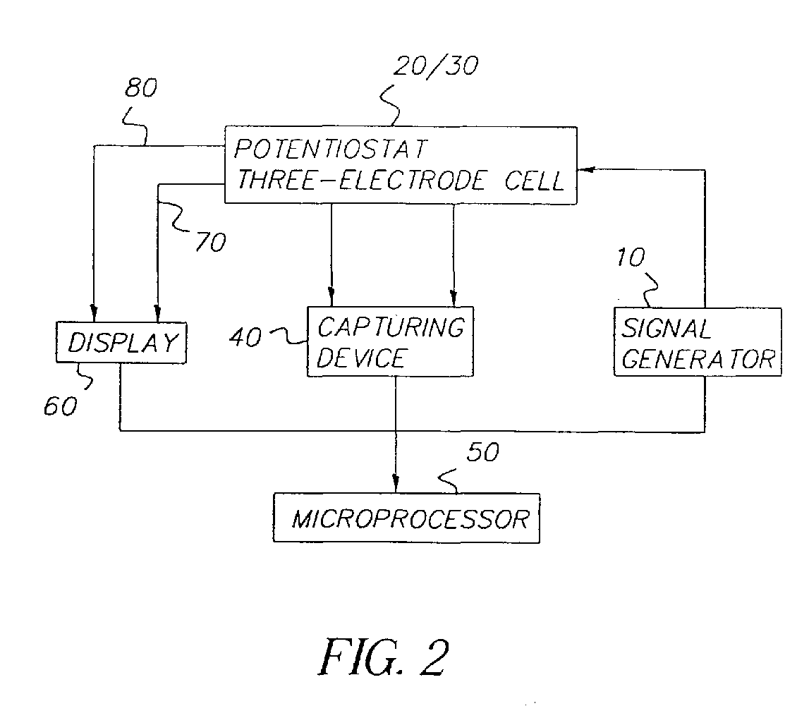
- the measuring device whose general flow chart is illustrated in Figure 2 comprises a generator 10 capable of generating at least one voltage ramp provided to supply the three-electrode cell 30.
- a digital signal is generated and converted into an analog signal by a digital/analog converter.
- the analog signal is sent to the three-electrode cell 30 via a potentiostat 20.
- the voltage at the terminals of the three-electrode cell 30 thus increases in time.
- the potentiostat 20 enables a constant potential difference to be maintained across the indicator electrode 32 and the reference electrode 31 of the three-electrode cell 30.
- An analog/digital converter is provided to convert the analog signal recovered from the potentiostat output as a digital signal.
- the device also comprises a capturing device 40 for capturing the digital signal of the analog/digital converter, which is representative of the amperage at the terminals of the three-electrode cell 30.
- the capturing device 40 captures this signal at the potentiometer output.
- a microprocessor 50 is provided to compare the values captured by the capturing device 40 to each other.
- the microprocessor 50 is for example a general use microprocessor such as an Intel Pentium 80*86® or a Motorola, a microcontroller such as for example an Intel 8051® or a signal processor.
- the microprocessor 50 is also utilized to control the signal generator 10, that is it generates and calculates the increments of the voltage gradient.
- the signal generator 10 generates a triangular gradient as is shown in Figure 4, in part A. It will be shown below that the gradient generator can generate different shape gradients according to the phase of use of the device.
- the voltage VOLTS equals the voltage of the gradient start VOLTS start (step 1200).
- the signal for the amperage measured in step 1300 by the indicator electrode 32 is sent to the capturing device 40.
- N values of the signal representing the amperage of the three-electrode cell are read in step 1400 using the capturing device 40, so that a stabilized value is obtained.
- a counter of the number of readings Read No which contains the value zero at the start in step 1100, counts the number of values captured V cap such that above the N th value, the voltage VOLTS is increased in step 1500 by a certain voltage value volts corresponding to an LSB or increment of the digital/analog converter and the counter Read No is reset to zero in step 1600.
- the counter is incremented in step 1700 using the microprocessor 50.
- the analog signal representative of the amperage measured at the terminals of the three-electrode cell is converted digitally by an analog/digital converter.
- the captured values V cap using the capturing device 40 are read in step 1800.
- the microprocessor 50 then produces a signal coming from the digital filtering of the captured values V cap so as to be free from high-frequency noise. This filtering also provides freedom from sudden variations of the signal generated by the generator 10.
- the filter utilized is a low-pass filter known to those skilled in the art.
- a memory is provided to record the maximum value MAX. This memory at the start contains the value zero in step 1000.
- Each filtered value V f is compared in step 2100 with the value MAX.
- step 2200 When a value V f is more than the value MAX, it is recorded in its place in step 2200. These steps are repeated throughout the duration of the gradient and each filtered value V f is compared with the maximum memorized value MAX. The maximum value recorded is shown in step 2300 on a display 60.
- the device comprises a saturation indicator 70 provided to check that the values captured by the capturing device 40 are values that correctly represent the amperage at the terminals of the three-electrode cell. It sometimes occurs that the output signal that is recovered at the analog/digital converter output is not representative of the amperage measured at the indicator electrode 32. This happens when the range of possible values of the potentiostat 20 output does not cover the whole signal representing the amperage measured at the terminals of the three-electrode cell 30 according to the voltage applied to its terminals. In this case, it is not possible to determine to which value captured by the capturing device the signal peak corresponds.
- the saturation indicator 70 will show an initial value, e.g. the value 1.
- the saturation indicator 70 will show a second value, e.g. 0.
- the saturation indicator 70 is read in step 1900 which gives a value 1 or 0.
- a value 1 or 0 of the saturation indicator 70 is linked and is shown on the display 60 in step 2300.
- an operating indicator 80 (Fig. 2) is utilized.
- This indicator 80 is provided to optimize the operation of the device.
- the starting program provides for conversion of the powering up voltage into the voltage value of the start of the gradient. If the user puts the electrodes in the bath before the end of this program's execution, the voltage applied to the electrode terminals will not be that of the start of the gradient and the values measured will be completely erroneous. Therefore an internal set point corresponding approximately to the value of the start of the gradient is provided. Thus, from powering up the device, the voltage generated is compared with a reference value.
- the voltage measured is sent to the potentiostat.
- a value, e.g. 1, is assigned to the operating indicator 80. This value is shown on the display 60 so as to warn the user that the device is in operating mode. If the value measured is less than this reference value, the internal set point is sent to the potentiostat.
- a value, e.g. 0, is assigned to the operating indicator 80. This value is displayed so that the user is informed that the device is not yet in operating mode.
- the generator 10 when the electrodes are reinitialized after a measurement, the generator 10 generates a signal in sinusoidal semi-arch like that illustrated in Figure 4 in part B. This then prevents pulse currents in the electrodes and bath.
- the device is used to measure the concentration of ascorbic acid in developing baths.
- the measurement of the concentration of ascorbic acid enables bath replenishment to be controlled in order to obtain products of high quality and reduce the volume of waste.
- a device can be used to measure the concentration of various developing agents whether for example black and white developing agents of the family of polyhydroxide aromatic compounds such as hydroquinone, monosulfate hydroquinone or color developing agents belonging to the phenylenediamines.
Abstract
The present invention relates to the automatic measurement of developing
agent concentration in a solution using a three-electrode cell.
The device comprises:
Description
- The present invention relates to the automatic measurement of developing agent concentration in a solution, and particularly a device for the automatic measurement of developing agent concentration in a developer bath.
- Photographic film developer baths include developing agents that are reducing compounds. As it is utilized, the developer bath becomes depleted of developing agent because of its development (oxidation-reduction reaction), and also because of aerial oxidation. This reduction of concentration of developing agent causes a reduction of bath activity. In order to maintain bath activity, the bath must be regularly replenished so as not to alter the quality of the developed products. However, it is desirable to replenish it to compensate solely for the variation of developing agent concentration and limit the volume of waste. Thus, regular and fast measurement of the developing agent concentration in developer baths is required.
- There are processes for measuring developing agent concentration that comprise utilizing a "voltamperometric" method. Three electrode cells are utilized to take measurements; they comprise three electrodes that are not fixed in relation to one another. The operator who takes the measurement has to arrange the electrodes one in relation to another in a position that enables a correct measurement. A problem found in this utilization is that the variation in position of the electrodes one in relation to another causes measurement variations. Another problem found with this type of cell is that the measurement cannot be done directly in the solution containing the developing agents. The solution is sampled and introduced into the cell. The reaction continues to take place while the solution is sampled and introduced into the cell. The measurement then made in the cell does not accurately give the concentration of developing agent in the development bath. Further, aerial oxidation could have occurred during the sampling.
- On the other hand, processes for measuring the concentration of developing agents that comprise using a voltamperometric method utilize costly apparatuses that additionally require operators to know about the chemical reactions taking place in the developing bath and a certain number of adjustments.
- An object of the invention is to develop a device for measuring the concentration of a developing agent that does not have the disadvantages described above and particularly a portable easy-to-use device, that is accurate and low cost.
- The present invention relates to a device for automatically measuring the concentration of a developing agent in a solution by means of a three-electrode cell. The device comprises a signal generator for generating at least one voltage gradient provided to supply the three-electrode cell, a capturing device provided to capture a signal representing the amperage measured at the three-electrode cell terminals according to a voltage applied to its terminals, and a microprocessor provided to compare successively one with another the values captured by the capturing device throughout the duration of the gradient.
- Other characteristics will appear on reading the description that follows, with reference to the drawings wherein:
- Figure 1 represents one embodiment of the three-electrode cell utilized in the present invention;
- Figure 2 represents a general flow chart of the invention;
- Figure 3 represents a diagram of the maximum capturing phase; and
- Figure 4 represents the voltage gradient generated by the voltage generator of the present invention.
-
- The device for the automatic measurement of the concentration of a developing agent according to the invention utilizes the voltamperometer principle. It is intended to operate with a three-electrode cell capable of being in contact with the developing bath containing the developing agent whose concentration is to be measured. The device enables measurement of the amperage output from the three-electrode cell according to the voltage applied to its terminals. The curve obtained has a peak and a step whose height is in proportion to the concentration of the developing agent.
- A three-
electrode cell 30 utilized with the invention device, illustrated in Figure 1, comprises areference electrode 31, anindicator electrode 32 and anauxiliary electrode 33. The three-electrode cell 30 can be integrated in the measuring device like the cell described in the French Patent Application FR 2776071. The three-electrode cell 30 is a compact cell that comprises aholder 300 having three locations, each location being designed to take aspecific electrode holder 300 has the threeelectrodes holder 300. Thereference electrode 31 is arranged so that its end is as close as possible to the end of theindicator electrode 32 so that the potential at the end of these two electrodes is approximately the same. The distance between the ends of thereference electrode 31 and theindicator electrode 32 is for example in the order of one millimeter. Theauxiliary electrode 33 is arranged so that the lines of current that flow between theindicator electrode 32 and theauxiliary electrode 33 are parallel and uniform. Theauxiliary electrode 33 has for example anangled end 331, parallel to the surface of the end of theholder 300 where the three electrodes open out. Anon-angled part 332 of theauxiliary electrode 33 is located outside theholder 300. Thenon-angled part 332 of theauxiliary electrode 33 located outside theholder 300 is electrically insulated in order to prevent disturbance in the current lines. - The
reference electrode 31 comprises a silver chloride rod submerged in a solution of potassium chloride saturated in silver chloride. The location or cavity in theholder 300 provided to take thereference electrode 31 has a straight part 3 la wherein the silver rod is located, and an oblique part 31b comprising the end which approaches the end of theindicator electrode 32. The potassium chloride is added to the cavity through anorifice 310. Theindicator electrode 32 can be made of platinum, gold or vitreous carbon. Preferably vitreous carbon will be selected. Theauxiliary electrode 33 can be of any material so long as its electrochemical properties do not affect the performance of the relevant electrode. For example it can be stainless steel. Ascrew 330 is provided to attach the auxiliary electrode to theholder 300. Theauxiliary electrode 33 can exceptionally be removed from theholder 300 by loosening thescrew 330, particularly when theindicator electrode 32 has to be polished. - The
holder 300 that has the three electrodes is made from an electrically insulating material that is photographically inert. For example Teflon® can be selected. - The three-
electrode cell 30 can also be independent to be inserted in the device solely for a measurement. For example it can be a disposable three-electrode cell for single use produced by a technique based on serigraphy like the cell described in French Patent Application FR 2776071. - The measuring device whose general flow chart is illustrated in Figure 2 comprises a
generator 10 capable of generating at least one voltage ramp provided to supply the three-electrode cell 30. A digital signal is generated and converted into an analog signal by a digital/analog converter. The analog signal is sent to the three-electrode cell 30 via a potentiostat 20. The voltage at the terminals of the three-electrode cell 30 thus increases in time. The potentiostat 20 enables a constant potential difference to be maintained across theindicator electrode 32 and thereference electrode 31 of the three-electrode cell 30. An analog/digital converter is provided to convert the analog signal recovered from the potentiostat output as a digital signal. The device also comprises a capturing device 40 for capturing the digital signal of the analog/digital converter, which is representative of the amperage at the terminals of the three-electrode cell 30. The capturing device 40 captures this signal at the potentiometer output. Amicroprocessor 50 is provided to compare the values captured by the capturing device 40 to each other. Themicroprocessor 50 is for example a general use microprocessor such as anIntel Pentium 80*86® or a Motorola, a microcontroller such as for example an Intel 8051® or a signal processor. Themicroprocessor 50 is also utilized to control thesignal generator 10, that is it generates and calculates the increments of the voltage gradient. - With reference to Figure 3, one can see the capture phase of the maximum of the signal representing the amperage at the terminals of the three-electrode cell according to the voltage applied to it. The
signal generator 10 generates a triangular gradient as is shown in Figure 4, in part A. It will be shown below that the gradient generator can generate different shape gradients according to the phase of use of the device. At the start of use, the voltage VOLTS equals the voltage of the gradient start VOLTSstart (step 1200). The signal for the amperage measured instep 1300 by theindicator electrode 32 is sent to the capturing device 40. Advantageously, for the same value of voltage VOLTS of the voltage gradient generated by thegenerator 10, N values of the signal representing the amperage of the three-electrode cell are read instep 1400 using the capturing device 40, so that a stabilized value is obtained. For example 10 readings are carried out. A counter of the number of readings Read No, which contains the value zero at the start instep 1100, counts the number of values captured Vcap such that above the Nth value, the voltage VOLTS is increased instep 1500 by a certain voltage value volts corresponding to an LSB or increment of the digital/analog converter and the counter Read No is reset to zero instep 1600. At each reading, the counter is incremented instep 1700 using themicroprocessor 50. The analog signal representative of the amperage measured at the terminals of the three-electrode cell is converted digitally by an analog/digital converter. The captured values Vcap using the capturing device 40 are read instep 1800. Themicroprocessor 50 then produces a signal coming from the digital filtering of the captured values Vcap so as to be free from high-frequency noise. This filtering also provides freedom from sudden variations of the signal generated by thegenerator 10. The filter utilized is a low-pass filter known to those skilled in the art. For each value captured Vcap by the capturing device, a filtered value Vf is obtained instep 2000. A memory is provided to record the maximum value MAX. This memory at the start contains the value zero instep 1000. Each filtered value Vf is compared instep 2100 with the value MAX. When a value Vf is more than the value MAX, it is recorded in its place instep 2200. These steps are repeated throughout the duration of the gradient and each filtered value Vf is compared with the maximum memorized value MAX. The maximum value recorded is shown instep 2300 on adisplay 60. - Advantageously, the device comprises a
saturation indicator 70 provided to check that the values captured by the capturing device 40 are values that correctly represent the amperage at the terminals of the three-electrode cell. It sometimes occurs that the output signal that is recovered at the analog/digital converter output is not representative of the amperage measured at theindicator electrode 32. This happens when the range of possible values of the potentiostat 20 output does not cover the whole signal representing the amperage measured at the terminals of the three-electrode cell 30 according to the voltage applied to its terminals. In this case, it is not possible to determine to which value captured by the capturing device the signal peak corresponds. So long as the signal value is less than the maximum value that the potentiostat can take, thesaturation indicator 70 will show an initial value, e.g. thevalue 1. When the signal value equals the maximum value, thesaturation indicator 70 will show a second value, e.g. 0. Immediately after each reading of the output value of the analog/digital converter, thesaturation indicator 70 is read instep 1900 which gives avalue value saturation indicator 70 is linked and is shown on thedisplay 60 instep 2300. Thus, when at the end of measuring a maximum current value linked with avalue 0 of thesaturation indicator 70 exists, the maximum current value will be displayed and the operator will see that this value is saturated. - Advantageously, an operating indicator 80 (Fig. 2) is utilized. This
indicator 80 is provided to optimize the operation of the device. In effect, when the device is powered up, the voltage generated at this moment is not that of the start of the voltage gradient but less. The starting program provides for conversion of the powering up voltage into the voltage value of the start of the gradient. If the user puts the electrodes in the bath before the end of this program's execution, the voltage applied to the electrode terminals will not be that of the start of the gradient and the values measured will be completely erroneous. Therefore an internal set point corresponding approximately to the value of the start of the gradient is provided. Thus, from powering up the device, the voltage generated is compared with a reference value. If the voltage from the digital/analog converter is more than or equal to this reference value, the voltage measured is sent to the potentiostat. A value, e.g. 1, is assigned to the operatingindicator 80. This value is shown on thedisplay 60 so as to warn the user that the device is in operating mode. If the value measured is less than this reference value, the internal set point is sent to the potentiostat. A value, e.g. 0, is assigned to the operatingindicator 80. This value is displayed so that the user is informed that the device is not yet in operating mode. - Advantageously, when the electrodes are reinitialized after a measurement, the
generator 10 generates a signal in sinusoidal semi-arch like that illustrated in Figure 4 in part B. This then prevents pulse currents in the electrodes and bath. - According to a particular utilization of the invention, the device is used to measure the concentration of ascorbic acid in developing baths. The measurement of the concentration of ascorbic acid enables bath replenishment to be controlled in order to obtain products of high quality and reduce the volume of waste. Clearly such a device can be used to measure the concentration of various developing agents whether for example black and white developing agents of the family of polyhydroxide aromatic compounds such as hydroquinone, monosulfate hydroquinone or color developing agents belonging to the phenylenediamines.
Claims (14)
- A device for automatically measuring the concentration of a developing agent in a solution using a three-electrode cell (30), the device comprising:a signal generator (10) capable of generating at least one voltage gradient intended to supply the three-electrode cell (30);a capturing device (40) of the signal representative of the amperage measured at the terminals of the three-electrode cell (30) according to the voltage applied to its terminals;a microprocessor (50) provided to compare successively one with another the values captured by the capturing device (40) throughout the duration of the gradient.
- A device according to Claim 1, which further comprises a potentiostat (20) linked to the three-electrode cell (30).
- A device according Claims 1 or 2 wherein the microprocessor (50) controls the signal generator (10) by generating and calculating the increments of the voltage gradient.
- A device according to any one of Claims 1 to 3 wherein the microprocessor (50) digitally filters the values captured by the capturing device (40) to be free from the high-frequency noise and/or sudden variations of the signal generated by the generator (10).
- A device according to any one of Claims 1 to 4, which further comprises a saturation indicator (70) provided to check that the values captured by the capturing device (40) are values to keep.
- A device according to any one of Claims 1 to 5 which further comprises an operating indicator (80) provided to check that the device is in operating mode.
- A device according to any one of Claims 1 to 6 which moreover comprises a display (60).
- A device according to any one of Claims 1 to 7 wherein the signal generator (10) generates various types of gradients according to the phases of use of the device.
- A device according to Claim 8 wherein the signal generator is capable of generating a triangular signal or a signal in sinusoidal semi-arch.
- A device according to any one of the previous Claims wherein the three-electrode cell (30) comprises a reference electrode (31), an indicator electrode (32) and an auxiliary electrode (33), and a holder (300) comprising three locations, each location being designed to take one electrode determined so as to maintain the three electrodes in a fixed position on in relation to another.
- A device according to Claim 10 wherein the holder (300) is made from an electrically insulating material that is photographically inert.
- A device according to Claim 10 or 11 wherein the auxiliary electrode (33) has an angled end (331), a non-angled part (332) of the auxiliary electrode (33) located outside the holder (300) is electrically insulated so as to create parallel and uniform current lines between the indicator electrode (32) and the auxiliary electrode (33).
- A device according to Claims 9 to 12 wherein an aperture (310) is provided in the location designed to take the reference electrode (31), the said aperture (310) being provided to introduce a solution constituting the reference electrode (31).
- Utilization of the automatic measuring device according to any one of Claims 1 to 13 to measure the concentration of ascorbic acid.
Applications Claiming Priority (2)
| Application Number | Priority Date | Filing Date | Title |
|---|---|---|---|
| FR9911551 | 1999-09-13 | ||
| FR9911551A FR2798467B1 (en) | 1999-09-13 | 1999-09-13 | DEVICE FOR AUTOMATICALLY MEASURING THE CONCENTRATION OF A DEVELOPING AGENT |
Publications (1)
| Publication Number | Publication Date |
|---|---|
| EP1085321A1 true EP1085321A1 (en) | 2001-03-21 |
Family
ID=9549883
Family Applications (1)
| Application Number | Title | Priority Date | Filing Date |
|---|---|---|---|
| EP00420185A Withdrawn EP1085321A1 (en) | 1999-09-13 | 2000-08-31 | Device for the automatic measurement of developing agent concentration |
Country Status (3)
| Country | Link |
|---|---|
| EP (1) | EP1085321A1 (en) |
| JP (1) | JP2001108644A (en) |
| FR (1) | FR2798467B1 (en) |
Citations (9)
| Publication number | Priority date | Publication date | Assignee | Title |
|---|---|---|---|---|
| GB1313796A (en) * | 1970-04-20 | 1973-04-18 | Ipc Services Ltd | Photographic processing |
| FR2273277A1 (en) * | 1974-05-28 | 1975-12-26 | Comalco Ltd | Dissolved substance concentration determination - by measuring current at anode effect onset during rapid cathode/anode voltage rise |
| US3957592A (en) * | 1974-07-29 | 1976-05-18 | Owens-Illinois, Inc. | Measurement of polarographic current |
| US3959108A (en) * | 1971-12-27 | 1976-05-25 | Plumpe Jr William H | System for automatically measuring and controlling the sulfate content of a chromium plating solution |
| DD288255A5 (en) * | 1989-10-02 | 1991-03-21 | Veb Filfabrik Wolfen,De | METHOD FOR DETERMINING THE CONCENTRATION VALUES OF DEVELOPER SUBSTANCES PHOTOGRAPHIC DEVELOPER BASED FOR REGENERATION |
| EP0552511A1 (en) * | 1992-01-20 | 1993-07-28 | Agfa-Gevaert N.V. | Method for controlling the PH of an ascorbic acid type developer |
| US5298132A (en) * | 1993-03-25 | 1994-03-29 | Hughes Aircraft Company | Method for monitoring purification treatment in plating baths |
| US5374892A (en) * | 1993-03-04 | 1994-12-20 | Georgia Tech Research Corporation | Digital electrochemical instrument with background compensation |
| EP0942280A1 (en) * | 1998-03-13 | 1999-09-15 | Eastman Kodak Company | Automatic measuring device for the concentration of a developing agent |
-
1999
- 1999-09-13 FR FR9911551A patent/FR2798467B1/en not_active Expired - Fee Related
-
2000
- 2000-08-31 EP EP00420185A patent/EP1085321A1/en not_active Withdrawn
- 2000-09-01 JP JP2000264846A patent/JP2001108644A/en active Pending
Patent Citations (10)
| Publication number | Priority date | Publication date | Assignee | Title |
|---|---|---|---|---|
| GB1313796A (en) * | 1970-04-20 | 1973-04-18 | Ipc Services Ltd | Photographic processing |
| US3959108A (en) * | 1971-12-27 | 1976-05-25 | Plumpe Jr William H | System for automatically measuring and controlling the sulfate content of a chromium plating solution |
| FR2273277A1 (en) * | 1974-05-28 | 1975-12-26 | Comalco Ltd | Dissolved substance concentration determination - by measuring current at anode effect onset during rapid cathode/anode voltage rise |
| US3957592A (en) * | 1974-07-29 | 1976-05-18 | Owens-Illinois, Inc. | Measurement of polarographic current |
| DD288255A5 (en) * | 1989-10-02 | 1991-03-21 | Veb Filfabrik Wolfen,De | METHOD FOR DETERMINING THE CONCENTRATION VALUES OF DEVELOPER SUBSTANCES PHOTOGRAPHIC DEVELOPER BASED FOR REGENERATION |
| EP0552511A1 (en) * | 1992-01-20 | 1993-07-28 | Agfa-Gevaert N.V. | Method for controlling the PH of an ascorbic acid type developer |
| US5374892A (en) * | 1993-03-04 | 1994-12-20 | Georgia Tech Research Corporation | Digital electrochemical instrument with background compensation |
| US5298132A (en) * | 1993-03-25 | 1994-03-29 | Hughes Aircraft Company | Method for monitoring purification treatment in plating baths |
| EP0942280A1 (en) * | 1998-03-13 | 1999-09-15 | Eastman Kodak Company | Automatic measuring device for the concentration of a developing agent |
| FR2776071A1 (en) * | 1998-03-13 | 1999-09-17 | Eastman Kodak Co | DEVICE FOR AUTOMATICALLY MEASURING THE CONCENTRATION OF A DEVELOPING AGENT |
Also Published As
| Publication number | Publication date |
|---|---|
| JP2001108644A (en) | 2001-04-20 |
| FR2798467B1 (en) | 2001-11-02 |
| FR2798467A1 (en) | 2001-03-16 |
Similar Documents
| Publication | Publication Date | Title |
|---|---|---|
| EP0459782B1 (en) | Amperimetric measurement with cell electrode deplating | |
| Kounaves | Voltammetric techniques | |
| KR960016170B1 (en) | Method and apparatus for conducting electrochem-iluminescent measurements | |
| WO1997008544A1 (en) | Handheld electromonitor device | |
| JP3104247B2 (en) | Electrochemical detector | |
| JPH09222415A (en) | Electrochemical gas sensor and method for sensing electrochemical active gas in gas mixed material | |
| US4321113A (en) | Electronic calibration of electrochemical sensors | |
| EP1085321A1 (en) | Device for the automatic measurement of developing agent concentration | |
| US4244800A (en) | Apparatus for use in rapid and accurate controlled-potential coulometric analysis | |
| Clem et al. | Modularized digitizing time-synchronizing current-sampling system for electroanalytical studies | |
| US6228237B1 (en) | Automatic measuring device for the concentration of a developing agent | |
| EP0269794A2 (en) | Method for operating an electrochemical cell having redox potential applied thereto | |
| EP0456154A2 (en) | Improved pH and concentration meter | |
| JP3354054B2 (en) | Residual chlorine meter | |
| JP3041437B2 (en) | Salinity measuring device | |
| JPH0298661A (en) | Method for measuring residual chlorine without being affected by disturbing component | |
| JP3437677B2 (en) | Voltammetry and equipment used therefor | |
| US3486998A (en) | Controlled potential coulometer | |
| JP2512623B2 (en) | Detector | |
| Czajkowski et al. | Automatic apparatus for precise measuring and recording of pzc value of liquid electrodes and its application | |
| JPH1164275A (en) | Oxidation-reduction potential measuring device | |
| KR0130943B1 (en) | Portable metal zon analyzer and method | |
| JPS60178347A (en) | Method and apparatus for pulse electrolytic analysis | |
| RU2092830C1 (en) | Microprocessor voltage-current analyzer of heavy metals | |
| Sakurai et al. | A New Method for the Precise Measurement of the Polarographic Current and Its Application in Digital Polarography |
Legal Events
| Date | Code | Title | Description |
|---|---|---|---|
| PUAI | Public reference made under article 153(3) epc to a published international application that has entered the european phase |
Free format text: ORIGINAL CODE: 0009012 |
|
| AK | Designated contracting states |
Kind code of ref document: A1 Designated state(s): DE FR GB |
|
| AX | Request for extension of the european patent |
Free format text: AL;LT;LV;MK;RO;SI |
|
| 17P | Request for examination filed |
Effective date: 20010910 |
|
| AKX | Designation fees paid |
Free format text: DE FR GB |
|
| STAA | Information on the status of an ep patent application or granted ep patent |
Free format text: STATUS: THE APPLICATION HAS BEEN WITHDRAWN |
|
| 18W | Application withdrawn |
Effective date: 20051125 |