EP1084838A1 - Printing press - Google Patents
Printing press Download PDFInfo
- Publication number
- EP1084838A1 EP1084838A1 EP00120306A EP00120306A EP1084838A1 EP 1084838 A1 EP1084838 A1 EP 1084838A1 EP 00120306 A EP00120306 A EP 00120306A EP 00120306 A EP00120306 A EP 00120306A EP 1084838 A1 EP1084838 A1 EP 1084838A1
- Authority
- EP
- European Patent Office
- Prior art keywords
- printing plate
- plate
- guide
- printing
- discharged
- Prior art date
- Legal status (The legal status is an assumption and is not a legal conclusion. Google has not performed a legal analysis and makes no representation as to the accuracy of the status listed.)
- Granted
Links
Images


Classifications
-
- B—PERFORMING OPERATIONS; TRANSPORTING
- B41—PRINTING; LINING MACHINES; TYPEWRITERS; STAMPS
- B41F—PRINTING MACHINES OR PRESSES
- B41F27/00—Devices for attaching printing elements or formes to supports
- B41F27/12—Devices for attaching printing elements or formes to supports for attaching flexible printing formes
- B41F27/1206—Feeding to or removing from the forme cylinder
-
- B—PERFORMING OPERATIONS; TRANSPORTING
- B41—PRINTING; LINING MACHINES; TYPEWRITERS; STAMPS
- B41F—PRINTING MACHINES OR PRESSES
- B41F33/00—Indicating, counting, warning, control or safety devices
- B41F33/0018—Protection means against injury to the operator
Definitions
- the present invention relates to a printing press comprising means for holding a new printing plate supplied to a plate cylinder and a discharged printing plate discharged from the plate cylinder.
- a printing press comprising means for holding a new printing plate supplied to a plate cylinder and a discharged printing plate discharged from a printing plate, wherein a supporting device for supporting the new printing plate and the discharged printing plate is pivotally provided at a protection member for moving upwardly, the supporting device is rotated so as to approach a position near the plate cylinder after moving the protection member upwardly in order to exchange the printing plate.
- the supporting device is rotated so as to approach to a position near the plate cylinder after moving the protection member upwardly in order to exchange the printing plate. Therefore, during an exchange operation, a portion surrounded by the plate cylinder of the printing unit beyond the plate cylinder of a printing unit is released. It would be afraid of falling tools into an inner portion of the printing unit.
- Japanese Patent Unexamined Publication No. 6-31901 discloses a thin plate pivotally attached at a surface confronting to the printing plate of a protection member for moving upwardly in order to exchange a printing plate by shifting the protection member to a guide position for guiding the discharged printing position and the new printing portion from a shelter position.
- a purpose of the present invention is to provide a printing press for setting a new printing plate and picking up a discharged printing plate, wherein a portion beyond a printing unit can be protected in a printing plate exchange operation.
- a printing press comprises a pair of left and right frames, a cover movably supported between a closing position for closing at least one part of a space formed between the pair of left and right frames and a releasing position for releasing the space, means for holding a printing plate movably supported between a shelter position for holding a new printing plate supplied to a plate cylinder or holding a discharged printing plate discharged from the plate cylinder and an operation position for supplying the new printing plate to the plate cylinder or storing the discharged printing plate discharged from the plate cylinder , the means for holding the printing plate located at an exterior side with respect to the cover, wherein the means for holding a printing plate can be moved between the shelter position and the operation position while the cover is located at the closing position.
- the means for holding a printing plate further comprising a first guide member for supporting one side surface of the printing plate and a second guide member for supporting the opposite surface of the printing plate, wherein the cover comprises an opening portion corresponding to one of the first and second guide members.
- the means for holding a printing plate comprising a first guide member for supporting one side surface of the printing plate and a second guide member for supporting the opposite surface of the printing plate, wherein the cover comprises a plurality of spaces separated with an interval along an axial direction of the plate cylinder, the spaces are corresponding to one of the first and second guide members.
- the means for holding a printing plate swingably supported at the both sides of the cover in an axial direction of the plate cylinder and the maximum oscillating radius of the cover within the means for holding the printing plate is shorter than the maximum oscillating radius of the means for holding the printing plate.
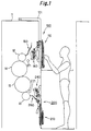
- Fig. 1 is a schematic view of a device for feeding a printing plate to a plate cylinder of a printing press, particularly to an offset sheet printing press.
- Fig. 2 shows an upper portion of the device as shown in Fig. 1.
- Fig. 3 shows a partial enlarged view of the device taken along a line III-III in Fig. 2.
- Fig. 4 shows a partial enlarged view of the device taken along a line IV-IV in Fig. 3.
- Fig. 5 shows a partial enlarged view of the device taken along a line V-V in Fig. 2.
- Fig. 6 shows a partial enlarged view of the device taken along a line VI-VI in Fig. 5.
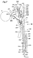
- Fig. 7 shows a lower portion of the device as shown in Fig. 1.
- Fig. 8 shows a partial enlarged view taken along a line VIII-VIII as shown in Fig. 7.
- Fig. 9 shows a partial enlarged view taken along a line IX-IX as shown in Fig. 8.
- Fig. 10 shows a partial enlarged view taken along a line X-X as shown in Fig. 9.
- Fig. 11 is a drawing taken along a line XI-XI as shown in Fig. 10.
- an upper plate cylinder 12 is provided at a location between a pair of upper right- and upper left- portions of the frames 11 of a printing unit.
- the upper cylinder 12 confronts with an upper rubber cylinder 14.
- a lower plate cylinder 13 is provided at a location between a pair of lower right- and lower left- frames 11.
- the lower plate cylinder 12 confronts with a lower rubber cylinder 15.
- the upper rubber cylinder 14 and the lower rubber cylinder 15 confront each other and a printed medium such as a web member is passed through the pair of the rubber cylinders 14 and 15.
- ink and dampening water is supplied from an ink supply device and a water supply device (not shown) to the plate cylinders 12, 13, respectively, ink corresponding to a picture pattern on plates of the plate cylinders 12 and 13 is transferred to the rubber cylinders 14 and 15, respectively, so that double sides of a printed medium are printed by passing between the rubber cylinders 14 and 15.
- an upper printing portion comprises the upper plate cylinder 12, the upper rubber cylinder 14, the ink supply device and the water supply device and a lower printing portion comprises the lower plate cylinder 13, the lower rubber cylinder 15, the ink supply device and the water supply device.
- an upper plate exchange device 100 is provided near the upper plate cylinder 12.
- the upper plate exchange device 100 comprises the following components.
- one end of a L-shaped support arm 101 is supported so as to rotate along the same rotational direction of the upper plate cylinder 12. As shown in Fig. 2 and Fig. 3, the opposite end of the support arm 101 is supported so as to rotate along the same rotational direction of the upper plate cylinder 12.
- An upper plate holding device 110 is means for holding a printing plate of a printing press according to the present invention and supported between the support frames 102 so as to rotate along the same rotational direction of the upper plate cylinder 12.
- the upper plate holding device 110 comprises the following components.
- a supporting axis 111 is connected and supported at a location between the support frames 102 so as to rotate along the same rotational direction of the upper plate cylinder.
- Each end portion of a pair of plate-shaped guide frames 112, 113 arranged along an axial direction is connected and supported to a respective end of the supporting axis.
- each opposite end of the guide frames 112 (113) is connected and fixed at a base end portion 114a (115b) of the first- (second-) guide portion 114 (115) extending toward one end of the guide frame 112 (113) substantially parallel to the longitudinal direction of the guide frame 112 (113).
- a space is provided between the guide frames 112, 113 and the first guide member 114 so as to form a stored portion 116a for storing a discharged printing plate 2.
- the upper holding device 110 When the upper holding device 110 is positioned as shown in Fig. 2, one end of the discharged plate 2 stands on the base end portion 114a of the first guide member 114 and a surface of the discharged printing plate 2 is supported by the guide frames 112 and 113 and the opposite surface of the discharged plate 2 is supported by the first guide member 114.
- a space is provided between the first and second guide members 114 and 115 so as to form a stored portion 116b for storing a new printing plate 1.
- a new printing plate 1 stands on the base end portion 115b of the second guide portion 115, one surface of the new printing plate 1 is supported by the first guide member 114 and the opposite surface of the new printing plate 1 is supported by the second guide member 115.
- means for storing a discharged printing plate is constituted by the guide frames 112 and 113, the first guide member 114 and so on and means for storing a new printing plate is constituted by the first and second guide members 114 and 115.
- a link plate 129 is connected and fixed at the supporting axis 111.
- a front end of an actuator 130 is pivotally connected.
- a base end of the actuator 130 is swingably supported by the support frame 102.
- moving means comprises the link plate 129 and the actuator 130.
- a hooking member 115a is affected as a release member and outwardly protruded from the guide frame 113.
- a plurality of guide rollers 117 for rotating along the same rotational direction of the upper printing plate cylinder 12 are provided along the longitudinal direction of the guide frames 112 and 113 separated with a predetermined interval.
- a contacting plate 118 for restricting the new printing plate 1 sliding along a width direction is attached through a bracket (not shown).
- a rodless cylinder 119 (120) is attached as moving means wherein an axial direction of the cylinder 119 (120) is arranged along the longitudinal direction of the guide frame 112 (113).
- a base end portion 121a of a U-shaped supporting member 121 of which an opening end is confronting to a front edge of the guide frame 112 is attached to the rodless cylinder 119.
- the supporting member 121 can be slid along the longitudinal direction of the guide frame 112 between a position as shown in Fig. 12 described below in detail and a stored position as shown in Fig. 13 by the rodless cylinder 119.
- a length of a connecting portion 121c is designed so as to position a height of a front end 121b of the supporting member 121 at the same level of an extending portion of the guide member 114.
- a base end of the guide member 123 is connected and fixed, wherein a longitudinal direction is arranged along a longitudinal direction of the guide frame 112.
- a base end of the hook 125 with a claw portion 125a provided at a tip portion is affected as the discharged printing plate holding member and supported so as to rotate along the same rotational direction of the supporting axis 111.
- the hook 125 is moved by the dead weight itself so as to position the claw portion 125a at the base end portion 121a so that the claw portion 125a is advanced into the stored portion 116a.
- the hook 125 is moved by the dead weight itself so as to overlap the claw portion 125a on the front end portion 121b so that the claw proton 125a is going out from the stored portion 116a.
- the hook 125 is located nearer than the connecting portion 121c of the supporting member 121 with respect to a front end of the guide frame 112. In other words, when the hook 125 is located in the stored position, the hook 125 is positioned at an upper stream side with respect to the base end 114a located at a down stream end of the stored portion 116a in the discharged printing plate storing direction. A length between a pivotal point of the hook 125 and the base end portion 114a is longer than a length between the pivot point of the hook 125 and the claw portion 125a.
- a length between the above pivot point of the hook 125 in the stored position and an end portion of the storing portion 116a at a down stream side in the discharged printing plates storing direction is longer than a distance between the pivot point and the front end portion of the hook 125.
- a stopper pin 127 is protruded and mounted as a pivot restricting member at the front end portion 121b of the support member 121 near the base end of the hook 125.
- the stopper pin 127 avoids for the claw portion 125a of the hook 125 advanced to the stored portion 116a toward the front end side of the guide member 123.
- the base end side 122a of the U-shaped support member 122 of which an opening portion confronts toward the front end side of the guide frame 113 is provided at the rodless cylinder 120.
- the support member 122 can be slid between a stored position as shown in Fig. 13 and a position as shown in Fig. 14 by the rodless cylinder 120.
- a length of the connecting portion 122c is designed so as to locate the front end portion 122b of the supporting member 122 slightly higher than the extending portion of the guide portion 115.
- the hook 126 having a claw portion 126a at the front end is affected as means for holding a new printing plate and swingably supported by the front end 122b of the support member 122 so as to rotate along the same rotational direction of the support axis 111.
- the claw portion 126a of the hook 126 is moved to the base end 122a by the dead weight so as to advance the claw portion 126a into the stored portion 116b.
- the claw portion 126a is moved by the dead weight so as to overlap on the front end portion 122b so that the claw portion 126 can go out from the stored portion 116b.
- the hook 126 is located nearer than the connecting portion 122c of the supporting member 122 with respect to the front end of the guide frame 113.
- the hook 126 when the hook 126 is in the stored position, the hook 126 is positioned at the down stream with respect to the base end 115b which is positioned at an upper stream with respect to the stored portion 116b in a new printing plate supply direction.
- a length between a pivot point of the hook 126 and the base end portion 115b is longer than a length between a pivot point and the claw portion 126a of the hook 126.
- a length between the pivot point of the hook 126 in the stored position and an upper stream end of the stored portion 116b in the new printing plate supply direction is longer than a length of the pivot point and the front end of the hook 126.
- a stopper pin 128 is protruded and mounted as a pivot restricting member at the front end portion 122b of the support member 122 near the base end of the hook 126.
- the stopper pin 128 avoids for the claw portion 126a of the hook 126 advanced to the stored portion 116b toward the front end side of the guide member 115.
- a press plate 124 is affected as a contacting member and protruded at a portion between the guide portions 114 and 115 of the connecting portion 122c of the supporting member 122.
- each base end of a pair of pivot frames 141 of an upper first plate guide device 140 is pivotally connected and supported at a respective side of the upper plate cylinder 12 with respect to the supporting axis 111 of the support frame 102 so as to rotate the frame 141 along the same direction of the supporting axis 111.
- the upper first plate guiding device 140 comprises the following components.
- a fixed guide plate 142 for guiding a movement of a discharged printing plate 2 is attached at the pivotal frame 141.
- a front end of an actuator 143 is pivotally connected to the pivotal frame 141.
- the support frame 102 is swingably supported at a base end of the actuator 143. That is, the pivotal frame 141 can be rotated by extending/contracting the actuator 143 so that the pivotal frame 141 can be rotated between a guide position for guiding a new printing plate 1 and a discharged printing plate 2 adjacent the upper plate cylinder 12 (as shown in Fig. 12) and a shelter position (see Fig. 2) released from the upper plate cylinder 12.
- a middle portion of a link plate 144 is pivotally connected to the pivotal frame 141.
- a guide plate 145 is attached at a front end of the link plate 144 and affected as a straddle guide.
- a front end of the actuator 146 is connected to a base end of the link plate 144.
- a base end of the actuator 146 is swingably supported by the pivotal frame 141. That is, the guide plate 145 can be moved between a discharged printing plate guiding position (see Fig. 12) and a new printing plate guiding position (as shown in Fig. 14) by extending/contracting the actuator 146 though the link plate 144 (described in detail herein below).
- a rotational axis 147 is swingably supported so as to rotate along the same rotational direction of the upper plate cylinder 12.
- a base end of a support plate 148 is connected and fixed at the rotational axis 147.
- Guide rollers 149 are rotatably provided at a front end of the support plate 148.
- a U-shaped turning plate of which a longitudinal direction is arranged along the axial direction of the upper plate cylinder 12 is connected to the rotational axis 147.
- One end of a connecting plate 151 is connected and fixed at the rotational axis 147.
- a front end of an actuator 152 is pivotally connected to the opposite end of the connecting plate 151.
- a base end of the actuator 152 is swingably supported by the turning frame 141.
- the rotational axis is rotated through the connecting plate 151 by extending/contracting the actuator 152 so that the guide rollers 149 and the turning plate 150 can be moved.
- a positioning plate 153 for adjusting a position of a printing plate along a width direction is attached to the pair of turning frames 141.
- an upper second printing plate guide device is provided near the upper plate cylinder 12.
- the upper second printing plate guide plate 160 comprises a guide plate 161 as a guiding member and a plurality of guiding rollers 162 pivotally provided at an end confronting with the upper plate cylinder 12 of the guide plate 161.
- an upper press roller 171 is provided near the upper plate cylinder 12 in order to approach to and released from the upper plate cylinder 12.
- a safety cover 103 for covering the printing press according to the present invention is provided for dividing at least one portion in a space between an internal portion and an external portion of the upper printing portion.
- the stored portions 116a and 116b of the upper printing plate holding device 110 are located at an exterior side with respect to the safety cover 103 and the guide frames 112 and 113, the rodless cylinders 119 and 120, base end portions 121a and 122a of the support members 121 and 122 and the upper first printing plate guide device 140 positioned at a left side with respect to the stored portion 116a of the upper printing plate holding device 110 as shown in Fig.
- the safety covers 103 provides a plurality of spaces 103a so as to provide spaces 103a corresponding to the guide frames 112 and 113 of the upper printing plate holding device 110, the rodless cylinders 119 and 120 and base end portions 121a and 122a of the supporting members 121 and 122.
- the safety cover 103 is swingably supported by the frame 11 through support members such as the support arm 101, the support frame 102 and so on so that at least one space formed between the pair of frames 11 can be shifted from/to a closed position for closing the space to/from a released position for releasing the space.
- the upper printing plate holding device 110 is supported by the safety cover 103 through the support frame 102 in order to rotate the upper printing plate holding device 110 to the operation position (as shown in Fig. 12) relatively to the safety cover 103.
- a safety cover 103 formed between the left side guide frame 112 and the right side guide frame 113 of the upper printing plate holding device 110 is shorter than a longitudinal length between the guide frames 112 and 113 of the upper printing plate holding device 110 so that the safety cover 103 can be turned with the maximum rotational radius smaller than the maximum rotational radius of the upper printing plate holding device 110.
- a lower printing plate exchange device 200 is provided near the lower plate cylinder 13.
- the lower printing plate exchange device 200 comprises the following components.
- a supporting axis 201 is supported at the left- and right- frames 11, wherein an axial direction of the supporting axis 201 is arranged toward the axial direction of the lower plate cylinder 13.
- a safety cover 203 for covering the printing press according to the present invention is pivotally connected and supported, wherein the safety cover 203 comprises opening portions 203a and 203b and a slit 203c.
- the safety cover 203 is swingably supported by the frames 11 through the support axis 201 so that at least one space formed between the pair of the frames 11 can shift between a close position for closing the space and a release position for releasing the space.
- the longitudinal distance of the safety cover 203 is shorter than that of the guide frames 212 and 213 of the upper printing plate holding device 210 as described below so that the maximum oscillating radius of the safety cover 203 can be shorter than the maximum oscillating radius of the lower printing plate holding device 210.
- a safety cover 202 with opening portions 202a ⁇ 202c is fixed at lower portions of the left side and right side of the frames 11.
- a rotational axis 211 of the lower printing plate holding device 210 is affected as means for holding a printing plate in the printing press according to the present invention and pivotally connected and supported so as to rotate along the same rotational direction of the lower plate cylinder.
- the lower printing plate holding device 210 comprises the following components.
- each end of a pair of a plate-shaped guide frames 212 and 213 is arranged along the axial direction of the upper plate cylinder 13 and connected and fixed at the opening portions 203a and 203b of the safety cover 203 of the rotational axis 211, respectively.
- a plate-shaped support frame 217 is connected and fixed.
- a base end of the guide member 214 (215) arranged in parallel with the longitudinal direction of the guide frame 212 (213) and extending toward one end of the guide frame 212 (213) is connected and fixed.
- the guide members 214 and 215 are outwardly protruded from the opening portions 203a and 203b of the cover 203 so as to locate the lower printing plate holding device 210 at an exterior side with respect to the safety cover 203 as shown in Fig. 7 and form a space therebetween in order to provide a stored portion 216b for storing the discharged printing plate 2.
- a space is provided between the guide frames 212 and 213 and the guide member 214 so as to provide a stored portion 216a for storing the new printing plate 1.
- means for storing a new printing plate comprises the above described guide frames 212 and 213 and the guide member 214 and means for storing a discharged printing plate comprises the guide members 214 and 215.
- link plate 229 One end of the link plate 229 is connected and fixed to the rotational axis 211. The opposite end of the link plate 229 is pivotally connected to the front end of the actuator 230. A base end of the actuator 230 is swingably supported by the safety cover 203.
- the rotational axis 211 is rotated by extending and contracting the actuator 230 through the link plate 229 so that the lower printing plate holding device 210 comprising the guide frames 212 and 213 and the support 217 can move between a shelter position (as shown in Fig. 7) and an operation position (as shown in Fig. 16) described in detail hereinafter.
- the link plate 229, the actuator 230 and so on constitute moving means in the present embodiment.
- a contacting plate 218 for restricting the new printing plate sliding in the width direction is attached to the guide frame 213 through a bracket.
- the actuators 219 and 220 is attached at an exterior side of the guide frames 212 and 213 with respect to a confronting surface of the guide frames 212 and 213, respectively, wherein the axial direction of the actuators 219 and 220 is arranged along the longitudinal direction of the guide frames 212 and 213, respectively.
- a support device 221 is pivotally attached at a front end of a rod of the actuator 219 by extending and contracting the rod of the actuator 219 between the positions as shown in Figs. 17 and 18.
- An extrusion member for extruding a new printing plate is attached to the supporting member 221.
- the extrusion member 223 is outwardly protruded from the opening portions 202a and 203a of the safety cover 202 and 203 so as to position between the safety covers 202 and 203 and the guide member 214 when the lower printing plate holding device 210 is positioned as shown in Fig. 7.
- a support member 224 is attached at a front end of a rod of an actuator 220 so as to move between positions as shown in Figs. 16 and 17 described blow by extending and contracting the rod of the actuator 220.
- a receiving member 224 for receiving a discharged printing plate 2 is provided at the support member 222.
- the receiving member 224 is outwardly protruded from the opening portions 202b and 203b of the safety covers 202 and 203 so as to position between the guide members 214 and 215 when the lower printing plate holding device 210 is positioned as shown in Fig. 7.
- base ends of a pair of frames 240a of the lower first printing plate guiding device 240 are pivotally connected and supported at an upper side of the support axis 201 so as to rotate along the same direction of the upper plate cylinder 13.
- the upper first printing plate guide device 240 comprises the following components.
- a rotational axis 241a of which the axial direction is arranged along the axial direction of the support axis 201 is attached to the frame 240a.
- the base end of the rotational frame (not shown) and a middle portion of a link plate 244 as a straddle guide are pivotally provided.
- a fixed guide plate 242 for feeding the discharged printing plate 2 is provided at the pivotal frame.
- a front end of the actuator 243 is pivotally connected to the pivot frame.
- a base end of the actuator 243 is swingably supported by the body frame 240a.
- the pivot frame is rotated by extending and contracting the actuator so that the guide plate 242 can be moved between a guide position near the lower plate cylinder and guiding the new printing plate 1 and the discharged printing plate 2 (see Fig. 16) and a shelter position released from the lower plate cylinder 13 (see Fig. 7).
- a guide plate 245 is affected as a straddle guide and provided at a front end of the link plate 244.
- a front end of the actuator 246 is connected at a base end of the link plate 244.
- the base end of the actuator 246 is swingably supported by the pivot frame.
- the guide plate 245 can be moved between a position for guiding a discharged printing plate (see Fig. 16) and a position for guiding a new printing plate (see Fig. 18) by extending and contracting the actuator 246 through the link plate 244 (described in detail hereinafter).
- a rotational axis 247 for rotating along the same direction of the lower plate cylinder 13 is rotatably supported.
- a base end of the support plate 248 is connected and fixed at the rotational axis 247.
- a guide roller 249 is rotatably provided at a front end of the support plate 248.
- a substantially U-shaped turning plate 250 of which a longitudinal direction is arranged along an axial direction of the lower plate cylinder 13 is connected and supported by the rotational axis 247.
- One end of a connecting plate 251 is connected and fixed at the rotational axis 247.
- a front end of an actuator 252 is pivotally connected to the opposite end of the connecting plate 251.
- the base end of the actuator 252 is pivotally connected to the pivot frame.
- Positioning plates 253 for positioning a plate along the width direction is provided at a pair of the pivot frames, respectively.
- a cover 254 is provided at the pivot frame.
- a lower second printing plate guide device 260 is provided near the lower plate cylinder 13.
- the lower second printing plate guiding device 260 comprises a guide plate 261 as a guiding member of which a base end is pivotally connected and supported by the support axis 201 and a plurality of guiding rollers at the end of the lower plate cylinder side (front end) of the guide plate 261.
- the lower second printing plate guiding device 260 can be moved between a guiding position for guiding a new printing plate 1 supplied to the lower plate cylinder 13 and a discharged printing plate discharged from the plate cylinder 13 and a shelter position located far from the lower plate cylinder 13.
- a lower press roller 271 is provided near the lower plate cylinder 13 so as to approach to and be released from the lower plate cylinder 13.
- the safety covers 202 and 203 locate the stored portions 216a and 216b of the lower printing plate holding device 210 at an exterior side with respect to the safety covers 202 and 203 and the guide frames 212 and 213, the support frame 217, the actuators 219 and 220, base end of support members 221 and 222 located at a left side with respect to the stored portion 216a of the lower printing plate holding device 210 as shown in Fig. 7 at an interior side with respect to the safety covers 202 and 203.
- the opening portions 202a, 202b, 203a and 203b and the slit 203c are formed at positions corresponding to the guide frames 212 and 213, the support frame 217, the actuators 219 and 220, the base ends of the support members 221 and 222 of the lower printing plate holding device 210, respectively.
- Fig. 12 is a drawing for explaining an exchange step in the upper printing plate exchange device.
- Fig. 13 is a drawing for explaining the next exchange step of the step in Fig. 12.
- Fig. 14 is a drawing for explaining the next exchange step of the step in Fig. 13.
- Fig. 15 is a drawing for explaining the next exchange step of the step in Fig. 14.
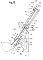
- Fig. 16 a drawing for explaining an exchange step in the lower printing plate exchange device.
- Fig. 17 is a drawing for explaining the next exchange step of the step in Fig. 16.
- Fig. 18 is a drawing for explaining the next exchange step of the step in Fig. 17.
- Fig. 19 is a drawing for explaining the next exchange step of the step in Fig. 18.
- the upper printing plate holding device 110 is located in the shelter position by arranging the guide frames 112 and 113 and guide members 114 and 115 in a up-down direction.
- a downstream side of the stored portion 116a is lower than the upstream side of the stored portion 116a in the discharge printing plate storing direction.
- the upstream side of the stored portion is lower than the downstream side of the stored portion in the new printing plate supply direction.
- a printing plate 1 of which a tail end is arranged at a lower side is inserted into the stored portion 116b between the guide members 114 and 115 of the upper printing plate holding device 110 with the contacting plate 118 so as to store the new printing plate 1 at the stored position.
- a longitudinal direction of the front end portions 121b and 122b of the support members 121 and 122 of the upper printing plate holding device 110 are positioned toward a straight direction, the hooks 125 and 126 are going out from the stored portions 116a and 116b by the dead weight so as to overlap on the front end portions 121b and 122b of the support members 121 and 122.
- the stored portion 116b is positioned at an exterior side with respect to the safety cover 103.
- a shelter position is located beyond the upper printing portion and the downstream side of the stored portion 116b is lower than the downstream of the stored portion 116b at the operating position in the printing plate supply direction, so that an operation for the stored portion 116b at the shelter position can be operated at the exterior and lower side with respect to the safety cover 103.
- a new printing plate 1 can be inserted from an opposite side of a contacting plate 118 of the stored portion 116b. Therefore, a new printing plate 1 can be set into the stored portion 116b simply and easily.
- the actuator 130 When the actuator 130 is contracted as shown in Fig. 12, the upper printing plate holding device 110 is moved to an operation position by turning the guide frames 112 and 113 around the rotational axis 111 so as to arrange the front end of the guide members 114 and 115 toward the upper plate cylinder 12.
- a downstream side of the stored portion 116a is located higher than an upstream side of the stored portion 116a in a discharged printing plate storing direction. That is, an opening portion of the support members 121 and 122 are downwardly inclined.
- the hooks 125 and 126 are moved so as to advance the claw portion 125a and 126a into the stored portions 116a, 116b.
- the stopper pins 127 and 128 restrict such a movement so that the claw portion 126a of the hook 126 can engage a tail end of the new printing plate so as to prevent the new printing plate from falling.
- the support member 121 is moved from a position as shown in Fig. 2 to a front end of the guide frame 112 (upstream side in the discharged printing plate storing direction) as shown in Fig. 12 by actuating the rodless cylinder 119 of the upper printing plate holding device 110.
- the guiding device 140 is moved to a guiding position by rotating the pivot frame 141 by extending the actuator 143 of the upper first printing plate guiding device 140, then the guide plate 145 for guiding the discharged printing plate 2 discharged from the upper plate cylinder 12 to the stored portion 116a of the upper printing plate holding device 110 by rotating the link plate 144 by contracting the actuator 146.
- the upper printing plate cylinder 12 is pressed and simultaneously rotated along an invert rotational direction so as to disengage the tail end of the printing plates engaged by means for holding the end of the printing plate of the upper plate cylinder 12 so that the tail end of the discharged printing sheet 2 is going out from the upper plate cylinder 12. Then, the discharged printing plate 2 is guided between the guide plates 142 and 145 of the upper first printing plate guide device 140 and fed to the stored portion 116a between the guide frames 112 and 113 and the guide member 123 of the upper printing plate holding device 110 by forwarding the tail end.
- the hook 125 is swingably supported so that the hook 125 is rotated by the tail end of the discharged printing plate 2 while the tail end is fed. After the tail end of the discharged printing plate 2 is passed through the hook 125, the hook 125 returned to an initial position (as shown in Fig. 12) by the dead weight.
- a disengagement of holding the tail end of the printing plate by the means for holding the edge of the printing plate is operated at an upstream point nearer than the edge confronting with the upper plate cylinder 12 of the guide plate 161 in an inverse rotational direction.
- the guide roller 149 and the turning plate 150 are returned to the shelter position by extending the actuator of the first printing press guide device 140.
- the rodless cylinder 119 of the upper printing plate holding device 110 are operated so as to return the support member 121 toward the base end of the guide frame 112 (downstream of the discharged printing plate storing direction), the claw 125a of the hook 125 engages the tail end of the discharged printing plate 2 and pulls the discharged printing plate 2 upwardly to the stored position of the stored portion 116a formed between the guide frames 112 and 113 and the guide member 123 so as to store the discharged printing plate 2 in the stored position of the stored portion 116a.
- the stopper pin 128 restricts the hook 125 rotating toward the upstream side in the discharged printing plate storing direction so that the discharged printing plate 2 can be pulled up certainly.
- the stopper pin 128 restricts the hook 125 rotating toward the upstream side in the discharged printing plate storing direction so that the discharged printing plate 2 can be pulled up certainly.
- the link plate 144 is rotated by extending the actuator 146 of the upper first printing plate guide device 140 so as to move the guide plate 145 to the new printing plate guide position for supplying the new printing plate 1 hold in the stored portion 116b of the upper printing plate holding device 110 to the upper plate cylinder 12 and to move the press roller 171 at an operation position so as to press the upper plate cylinder 12.
- the support member 122 is moved from the stored position of the stored portion 116a to the front end of the guide frame 113 (downstream in the new printing plate supply direction), the press plate 124 contacts with the tail end of the new printing plate 1 and the new printing plate 1 is fed toward the upper plate cylinder 12 (downstream in the new printing plate supply direction).
- the support member 122 is moved toward the front end of the guide frame 113 so as to feed the new printing plate 1 toward the upper printing cylinde3r 12, the hook 126 is caught and contacted with a catching portion 115a of the guide member 115 on the way so as to going out from the stored portion 116b.
- the tail end of the new printing plate 1 is unlocked from the hook 126 so that the new printing plate 1 is fed with positioning the width direction of the new printing plate 1 by the left and right positioning plates 153 of the supper first printing plate guide device 140 and stopped by contacting the engaged end with the press roller 171.
- the upper plate cylinder 12 is rotated clockwisely, the new printing plate 1 is wound and attached on the upper plate cylinder 12 from the engaged end.
- the upper printing plate holding device 110 is moved from the shelter position to the operation position so that the printing plate can be prevented from falling to an inside of the printing portion in an exchange operation.
- the pivot frame 141 is rotated by contracting the actuator 143 of the upper first printing plate guide device 140 as shown in Fig. 15 so as to move the guide device to the shelter position.
- the support member 122 is moved toward the base end of the guide frame 113 by actuating the rodless cylinder 120 of the upper printing plate holding device 110 and the guide frames 112 and 113 are rotated by extending the actuator 13 so as to move the printing plate holding device 110 to the shelter position then the guide frames 112 and 113 and the guide members 114 and 115 are rotated wherein the longitudinal direction thereof is arranged along an up and down direction.
- a downstream of the stored portion 116a is located lower than the upstream of the stored portion 116a in the discharged printing plate store direction.
- the upstream of the stored portion 116b is located lower than the downstream of the stored portion 116b in the new printing plate supply direction.
- the longitudinal direction of the front ends 121b and 122b of the support members 121 and 122 of the upper printing plate holding device 110 is arranged along a straight direction, the hooks 125 and 126 is rotated by the dead weight so as to go out from the stored portions 116a and 116b and overlaps the front ends 121b and 122b of the support members 121 and 122, respectively.
- the stored portion 116a is located at an exterior side with respect to the safety cover 103 and the safety cover 103 is positioned at a back side of the stored discharged printing plate 2 so as to form a guide surface.
- the shelter position is located beyond the upper printing portion and a position at the downstream of the stored portion 116b in the discharged printing plate storing direction is lower than the operation position so that an operation for the stored portion 116a in the shelter position can be worked at the lower position at the exterior side of the safety cover 103 protruded form the safety cover 103.
- the discharged printing plate 2 can be pick up from the stored portion 116a at the opposite side of the contacting plate 118, the discharged printing plate 2 can be removed from the stored portion 116a without an operator entering into adjacent printing units.
- the guide frames 212 and 213 and the guide members 214 and 215 of the lower printing plate holding device 210 are arranged along the up and sown direction so as to position the stored portions 216a and 216b at the shelter position which is at an exterior side with respect to the safety cover 203.
- the tail end of the new printing plate is positioned at the lower side and inserted into the stored position of the stored portion 216a of the lower printing plate holding device by contacting the new printing plate with the contacting plate 218.
- the stored portion 216b of the lower printing plate holding device 210 is located at the exterior side with respect to the safety cover 203 and the safety cover 203 is arranged along the stored portion 216b so that an operation for setting the new printing plate 1 with respect to the stored portion 216a at the shelter position can be worked at the exterior side of the safety cover 203 with the protection of the safety cover 203.
- the new printing plate 1 can be inserted from the opposite side of the contacting plate 218 of the stored portion 216a so that the new printing plate 1 can be set in the stored portion 216b without an operator entering into adjacent printing units. Thus, the new printing plate 1 can be easily set in the stored portion 216b.
- the pick-up member 224 is moved from the position as shown in Fig. 7 to a front end of the guide frame 213 as shown in Fig. 16 by contracting the actuator 220 of the lower printing plate holding device 210.
- the pivot frame is rotated by extending the actuator 243 of the lower first printing plate guide device 240 so as to move the lower first printing plate guide device 240 at the guiding position.
- the link plate 244 is rotated by shortening the actuator 246 so as to move the guide plate 245 to a discharged printing plate guide position for guiding the discharged printing plate 2 discharged from the lower plate cylinder to the stored portion 216b of the lower printing plate holding device 210.
- the press roller 271 is shifted to the operation position and pressed on the lower plate cylinder 13, while the lower plate cylinder 13 inversely rotated and the engagement of the tail end of the printing plate 2 with the means for holding the edge of the printing plate of the lower plate cylinder 13 is released.
- the tail end of the discharged printing plate 2 is going out from the lower plate cylinder 13, the discharged printing plate 2 is guided between the guide plates 242 and 245 of the lower first printing plate guide device 240.
- the discharged printing plate 2 is fed on the pick-up member 224 of the stored portion 216b between the guide frames 214 and 215 of the lower printing plate holding device 210 from the tail end.
- the disengagement of the tail end of the printing plate by the means for holding the tail end of the printing plate is operated at an upstream portion with respect to an end portion confronting with the lower plate cylinder 13 of the guide plate 261 in a inverse rotational direction of the lower plate cylinder 13.
- the guide rollers 249 and the turning plate 250 are returned to the shelter position by extending the actuator 252 of the lower first printing plate guide device 240.
- the pick-up member 225 is returned to the base end of the guide frame 213 by actuating the actuator 220 of the lower printing plate holding device 210.
- the discharged printing plate 2 is moved to the stored position of the stored portion 216b on the pick-up member 224 between the guide members 214 and 215 and stored in the stored position of the stored portion 216b while the pick-up member 224 engages with the tail end of the discharged printing plate 2.
- the link plate 244 is rotated by extending the actuator 246 of the lower first printing plate guide device 240 so as to move the guide plate 245 to the new printing plate guide device for supplying the new printing plate 1 hold in the stored portion 216a of the lower printing plate holding device 210 to the lower plate cylinder 12.
- the press roller 271 is shifted to the operation position so as to press the lower plate cylinder 13.
- the extrusion member 223 is moved to the front end of the guide frame 212 by contracting the actuator 219 of the lower printing plate holding device 210, the tail end of the new printing plate 1 is pushed by the pushing member 223 and fed toward the lower printing plate cylinder 13 while the width direction of the new printing plate 1 is accurately adjusted by the left- and right- positioning plates 252.
- the feeding operation is stopped once.
- the new printing plate 1 is wound and attached to the upper plate cylinder 12 from the engaged end.
- the lower printing plate holding device 210 can be shifted from the shelter position to the operation position so that tools can be prevented from falling into an internal portion of the printing portion in exchanging a printing plate exchange operation.
- the pivot frame is rotated by contracting the actuator 243 of the lower first printing plate guide device 240 of the actuator 243 so as to move the guide device 240 to the shelter position.
- the extrusion member 223 is moved toward the base end of the guide frame 212 by extending the actuator 219 of the lower printing plate holding device 210.
- the guide frames 212 and 213 are rotated by contracting the actuator 230 so as to move the printing plate holding device 210 to the shelter position.
- each component such as the guide frames 212 and 213 pass through the safety covers 202 and 203 and the opening portions 202a, 202b, 203a and 203b and the slit 203c and are stored at an interior side of the safety covers 202 and 203.
- the stored portion 216b of the lower printing plate holding device 210 is positioned at an exterior side with respect to the safety cover 203, an operation for the stored portion 216b at the shelter position can be worked at the exterior side with respect to the safety cover 203.
- the discharged printing plate 2 can be pick up from the stored portion 216b at an opposite side of the contacting plate 218, so that the discharged printing plate 2 can be removed from the stored portion 216b without an operator entering into adjacent printing units.
- the discharged printing plate 2 can be picked up from the stored portion very easily.
- the safety cover 103 is opened as shown in Fig. 20. Then, the support frame 102 integrally supported with the safety cover 103 is rotated around the support arm 101. The upper printing plate holding device 110 and the upper first printing plate guide device 140 are pulled from the frame 11. On the other hand, the support frame 240a of the lower first printing plate guide device 240 and the guide plate 261 of the lower second printing plate guide device 260 are rotated around the support axis 201, the lower first printing plate guide device 240 and the lower second printing plate guide device 260 are pulled from the frame 11 of the printing unit.
- the surrounding portions of the plate cylinders 12 and 13 and the rubber cylinders 14 and 15 of the printing portion in the printing unit can be released simultaneously with providing the working space at the surrounding portions of the plate cylinders 12 and 13 and the rubber cylinders 14 and 15 so as to be inspected easily.
- the support arm 101 of the upper printing plate exchange device 100 is rotated by the frame 11 of the printing unit from a position as described above as shown in Fig. 21, the upper printing plate holding device 110 and the upper first printing plate guide device 140 are located above the frame 11 of the printing unit, the lower printing plate holding device 210 with the safety cover 203 is pulled out from the printing unit by rotating the safety cover 203 of the lower printing plate exchange device 200 around the support axis 201.
- the surrounding portion of the ink supply device and the water supply device of the printing portion of the printing unit can be released simultaneously providing a working space at the surrounding portion of the ink supply device and the water supply device so as to be inspected easily.
- the above described upper printing plate exchange device 100 and lower printing plate exchange device 200 can obtain the following effects.
- the hooks 125 and 126 are pivotally provided at the front ends 121b and 122b of the support members 121 and 122, as shown in Fig. 22, instead of the hooks 125 and 126, it may be provided hooks 125' and 126' capable of sliding in a pair of slide grooves 121ba and 122ba formed at the front end portion 121b and 122b of the support members 121 and 122, respectively.
- the hooks 125' and 126' when the upper printing plate holding device 110 is switched to the operation position, the hooks 125' and 126' are slid by the dead weight so as to advance the claw portions 125'a and 126'a in the stored portions 116a, 116b (see Fig. 23A, Fig. 24A).
- the hook 125' advanced in the stored portion 116a the hook 125' is pushed by the tail end of the discharged printing plate 2 so as to go out from the stored portion 116a by feeding the discharged printing plate 2. At that time when the tail end of the discharged printing plate 2 passes, the hook 125' can slide into the stored portion 116a again by dead weight (see Fig. 23B).
- the hook 126' advanced in the stored portion 116b the hook 126' is caught by the hooking member 115a of the guide member 115 on the way, the hook 126' can be slid so as to go out from the stored portion 116b (see Fig. 24B).
- the hook 126 can be gone out from the stored portion 116b by contacting with the hooking member 115a of the guide member 115, instead of the hooking portion 115a, the hook 126 can be caught by a magnet member so that the hook 126 can be gone out from the stored portion 116b by moving the hook 126.
- a new printing plate and a discharged printing plate can be supplied and discharged by switching means for holding a printing plate from a shelter position to an operation position.
- the safety cover In a printing plate exchange operation, the safety cover can be closed. Thus, tools can be prevented from falling into an interior portion of the printing portion in the printing plate exchange operation.
- a printing plate holding device is hold at the cover side, the printing plate holding device can be released from an adjacent portion of the plate cylinder simultaneously with closing/opening the cover.
- the inspection operation can be improved more effectively.
- Almost members of a printing plate holding means except a stored portion at a shelter position can be stored at an interior side with respect to the cover so that an outward protruded volume from the cover can become small.
- a working space can be utilized effectively and the printing plate exchange operation can be improved more conveniently.
- the cover When the discharged printing plate is picked up from the stored portion of the means for holding a printing plate and the new printing plate is set in the stored portion, the cover can be utilized as a guide surface. Therefore, the new printing plate and the discharged printing plate can be set and discharged easily with the simple structure. A manufacturing cost can be reduced.
- the maximum rotational radius of the cover is shorter than the maximum rotational radius of the means for holding a printing plate, an operator between a pair of the means for holding the printing plate can open/close the cover easily without crashing on the cover in the inspection operation.
Abstract
Description
- The present invention relates to a printing press comprising means for holding a new printing plate supplied to a plate cylinder and a discharged printing plate discharged from the plate cylinder.
- It has been known a printing press comprising means for holding a new printing plate supplied to a plate cylinder and a discharged printing plate discharged from a printing plate, wherein a supporting device for supporting the new printing plate and the discharged printing plate is pivotally provided at a protection member for moving upwardly, the supporting device is rotated so as to approach a position near the plate cylinder after moving the protection member upwardly in order to exchange the printing plate.
- In the above described printing press, the supporting device is rotated so as to approach to a position near the plate cylinder after moving the protection member upwardly in order to exchange the printing plate. Therefore, during an exchange operation, a portion surrounded by the plate cylinder of the printing unit beyond the plate cylinder of a printing unit is released. It would be afraid of falling tools into an inner portion of the printing unit.
- For example, Japanese Patent Unexamined Publication No. 6-31901 discloses a thin plate pivotally attached at a surface confronting to the printing plate of a protection member for moving upwardly in order to exchange a printing plate by shifting the protection member to a guide position for guiding the discharged printing position and the new printing portion from a shelter position.
- However, in the embodiment disclosed in Japanese Patent Unexamined No. 6-31901, an operation for setting a new printing plate and picking up a discharged printing plate becomes complex since the thin plate is provided at the surface confronting to the plate cylinder of the protection member.
- A purpose of the present invention is to provide a printing press for setting a new printing plate and picking up a discharged printing plate, wherein a portion beyond a printing unit can be protected in a printing plate exchange operation.
- To resolve the above described subject, a printing press according to the present invention comprises a pair of left and right frames, a cover movably supported between a closing position for closing at least one part of a space formed between the pair of left and right frames and a releasing position for releasing the space, means for holding a printing plate movably supported between a shelter position for holding a new printing plate supplied to a plate cylinder or holding a discharged printing plate discharged from the plate cylinder and an operation position for supplying the new printing plate to the plate cylinder or storing the discharged printing plate discharged from the plate cylinder , the means for holding the printing plate located at an exterior side with respect to the cover, wherein the means for holding a printing plate can be moved between the shelter position and the operation position while the cover is located at the closing position.
- In the above described printing press according to the present invention, wherein the means for holding a printing plate is supported at a side of the cover.
- In the above described printing press according to the present invention, wherein the cover is swingably supported at a side of the frames.
- In the above described printing press according to the present invention, wherein the cover is swingably supported at a side of the support member swingably supported at a side of the frames.
- In the above described printing press according to the present invention, the means for holding a printing plate further comprising a first guide member for supporting one side surface of the printing plate and a second guide member for supporting the opposite surface of the printing plate, wherein the cover comprises an opening portion corresponding to one of the first and second guide members.
- In the above described printing press according to the present invention, the means for holding a printing plate comprising a first guide member for supporting one side surface of the printing plate and a second guide member for supporting the opposite surface of the printing plate, wherein the cover comprises a plurality of spaces separated with an interval along an axial direction of the plate cylinder, the spaces are corresponding to one of the first and second guide members.
- In the above described printing press according to the present invention, wherein the cover is swingably supported at a side of the frames, the means for holding a printing plate swingably supported at the both sides of the cover in an axial direction of the plate cylinder and the maximum oscillating radius of the cover within the means for holding the printing plate is shorter than the maximum oscillating radius of the means for holding the printing plate.
-
- Fig. 1 shows a schematic view of an embodiment of a printing plate exchange device of a printing press according to the present invention.
- Fig. 2 shows a schematic view of an upper printing plate exchange device as shown in Fig. 1.
- Fig. 3 shows a partially enlarged view of the device taken along a line III-III in Fig. 2.
- Fig. 4 shows a partially enlarged view of the device taken along a line IV-IV in Fig. 3.
- Fig. 5 shows a partially enlarged view of the device taken along a line V-V in Fig. 2.
- Fig. 6 shows a device taken along a line VI-VI in Fig. 5.
- Fig. 7 shows a schematic view of a lower printing plate exchange device as shown in Fig. 1.
- Fig. 8 shows a partially enlarged view of the device taken along a line VIII-VIII in Fig. 7.
- Fig. 9 shows a partially enlarged view of the device taken along a line IX-IX in Fig. 8.
- Fig. 10 shows a partially enlarged view of the device taken along a line X-X in Fig. 7.
- Fig. 11 shows a device taken along a line XI-XI in Fig. 10.
- Fig. 12 shows a step for exchanging a printing plate in the upper printing plate exchange device.
- Fig. 13 shows a step following the step as shown in Fig. 12.
- Fig. 14 shows a step following the step as shown in Fig. 13.
- Fig. 15 shows a step following the step as shown in Fig. 14.
- Fig. 16 shows a step for exchanging a printing plate in the lower printing plate exchange device.
- Fig. 17 shows a step following the step as shown in Fig. 16.
- Fig. 18 shows a step following the step as shown in Fig. 17.
- Fig. 19 shows a step following the step as shown in Fig. 18.
- Fig. 20 explains a maintenance operation to inspect a surrounding portion of a rubber cylinder and a plate cylinder.
- Fig. 21 explains a maintenance operation to inspect to a surrounding portion of an ink supply device.
- Fig. 22A is enlarged view of an essential part of another embodiment of a printing plate holding device according to the present invention.
- Fig. 22B is enlarged view of an essential part of another embodiment of a printing plate holding device according to the present invention.
- Fig. 23A and Fig. 23B explain an operation as shown in Fig. 22A.
- Fig. 24A and Fig. 24B explain an operation as shown in Fig. 22B.
-
- An embodiment of a printing press according to the present invention is described with reference to Fig. 1 to Fig. 11. Fig. 1 is a schematic view of a device for feeding a printing plate to a plate cylinder of a printing press, particularly to an offset sheet printing press. Fig. 2 shows an upper portion of the device as shown in Fig. 1. Fig. 3 shows a partial enlarged view of the device taken along a line III-III in Fig. 2. Fig. 4 shows a partial enlarged view of the device taken along a line IV-IV in Fig. 3. Fig. 5 shows a partial enlarged view of the device taken along a line V-V in Fig. 2. Fig. 6 shows a partial enlarged view of the device taken along a line VI-VI in Fig. 5. Fig. 7 shows a lower portion of the device as shown in Fig. 1. Fig. 8 shows a partial enlarged view taken along a line VIII-VIII as shown in Fig. 7. Fig. 9 shows a partial enlarged view taken along a line IX-IX as shown in Fig. 8. Fig. 10 shows a partial enlarged view taken along a line X-X as shown in Fig. 9. Fig. 11 is a drawing taken along a line XI-XI as shown in Fig. 10.
- As shown in Fig. 1, an
upper plate cylinder 12 is provided at a location between a pair of upper right- and upper left- portions of theframes 11 of a printing unit. Theupper cylinder 12 confronts with anupper rubber cylinder 14. On the other hand, alower plate cylinder 13 is provided at a location between a pair of lower right- and lower left- frames 11. Thelower plate cylinder 12 confronts with alower rubber cylinder 15. Theupper rubber cylinder 14 and thelower rubber cylinder 15 confront each other and a printed medium such as a web member is passed through the pair of therubber cylinders - When ink and dampening water is supplied from an ink supply device and a water supply device (not shown) to the
plate cylinders plate cylinders rubber cylinders rubber cylinders - In the present embodiment, an upper printing portion comprises the
upper plate cylinder 12, theupper rubber cylinder 14, the ink supply device and the water supply device and a lower printing portion comprises thelower plate cylinder 13, thelower rubber cylinder 15, the ink supply device and the water supply device. - As shown in Fig. 1, an upper
plate exchange device 100 is provided near theupper plate cylinder 12. The upperplate exchange device 100 comprises the following components. - At each upper end of the right- and left-
frames 11, one end of a L-shapedsupport arm 101 is supported so as to rotate along the same rotational direction of theupper plate cylinder 12. As shown in Fig. 2 and Fig. 3, the opposite end of thesupport arm 101 is supported so as to rotate along the same rotational direction of theupper plate cylinder 12. - An upper
plate holding device 110 is means for holding a printing plate of a printing press according to the present invention and supported between the support frames 102 so as to rotate along the same rotational direction of theupper plate cylinder 12. The upperplate holding device 110 comprises the following components. - As shown in Fig. 2 and Fig. 3, a supporting
axis 111 is connected and supported at a location between the support frames 102 so as to rotate along the same rotational direction of the upper plate cylinder. Each end portion of a pair of plate-shaped guide frames 112, 113 arranged along an axial direction is connected and supported to a respective end of the supporting axis. - As shown in Fig. 2 to Fig. 4, each opposite end of the guide frames 112 (113) is connected and fixed at a
base end portion 114a (115b) of the first- (second-) guide portion 114 (115) extending toward one end of the guide frame 112 (113) substantially parallel to the longitudinal direction of the guide frame 112 (113). - A space is provided between the guide frames 112, 113 and the
first guide member 114 so as to form a storedportion 116a for storing a dischargedprinting plate 2. When theupper holding device 110 is positioned as shown in Fig. 2, one end of the dischargedplate 2 stands on thebase end portion 114a of thefirst guide member 114 and a surface of the dischargedprinting plate 2 is supported by the guide frames 112 and 113 and the opposite surface of the dischargedplate 2 is supported by thefirst guide member 114. - A space is provided between the first and
second guide members portion 116b for storing anew printing plate 1. When the upperplate holding device 110 is positioned as shown in Fig. 2, anew printing plate 1 stands on thebase end portion 115b of thesecond guide portion 115, one surface of thenew printing plate 1 is supported by thefirst guide member 114 and the opposite surface of thenew printing plate 1 is supported by thesecond guide member 115. - In the above embodiment, means for storing a discharged printing plate is constituted by the guide frames 112 and 113, the
first guide member 114 and so on and means for storing a new printing plate is constituted by the first andsecond guide members - One end of a
link plate 129 is connected and fixed at the supportingaxis 111. At the opposite end of thelink plate 129, a front end of anactuator 130 is pivotally connected. A base end of theactuator 130 is swingably supported by thesupport frame 102. - That is, in the case that the
actuator 130 is extended, the supportingaxis 111 is rotated though thelink plate 129 so as to switch the upper printingplate holding device 110 including the guide frames 112 and 113 between a released position (as shown in Fig. 2) and an operation position (as shown in Fig. 12) as described below. In the embodiment, moving means comprises thelink plate 129 and theactuator 130. - At a front end of the
second guide portion 115, a hookingmember 115a is affected as a release member and outwardly protruded from theguide frame 113. At theguide member 114 between the guide frames 112 and 113, a plurality ofguide rollers 117 for rotating along the same rotational direction of the upperprinting plate cylinder 12 are provided along the longitudinal direction of the guide frames 112 and 113 separated with a predetermined interval. At theguide frame 13, a contactingplate 118 for restricting thenew printing plate 1 sliding along a width direction is attached through a bracket (not shown). - At each outside surface of the confronting guide frames 112 (113), a rodless cylinder 119 (120) is attached as moving means wherein an axial direction of the cylinder 119 (120) is arranged along the longitudinal direction of the guide frame 112 (113). A
base end portion 121a of a U-shaped supportingmember 121 of which an opening end is confronting to a front edge of theguide frame 112 is attached to therodless cylinder 119. The supportingmember 121 can be slid along the longitudinal direction of theguide frame 112 between a position as shown in Fig. 12 described below in detail and a stored position as shown in Fig. 13 by therodless cylinder 119. A length of a connectingportion 121c is designed so as to position a height of afront end 121b of the supportingmember 121 at the same level of an extending portion of theguide member 114. - At the
front end 121b of the supportingmember 121, a base end of theguide member 123 is connected and fixed, wherein a longitudinal direction is arranged along a longitudinal direction of theguide frame 112. At thefront end 121b of the supportingmember 121, a base end of thehook 125 with aclaw portion 125a provided at a tip portion is affected as the discharged printing plate holding member and supported so as to rotate along the same rotational direction of the supportingaxis 111. When the longitudinal direction of thefront end portion 121b of the supportingmember 121 is arraanged toward a direction as shown in Fig. 13 as described below, thehook 125 is moved by the dead weight itself so as to position theclaw portion 125a at thebase end portion 121a so that theclaw portion 125a is advanced into the storedportion 116a. When the longitudinal direction of thefront end portion 121b of the supportingmember 121 is arranged toward a straight direction as shown in Fig. 2, thehook 125 is moved by the dead weight itself so as to overlap theclaw portion 125a on thefront end portion 121b so that theclaw proton 125a is going out from the storedportion 116a. - Thus, the
hook 125 is located nearer than the connectingportion 121c of the supportingmember 121 with respect to a front end of theguide frame 112. In other words, when thehook 125 is located in the stored position, thehook 125 is positioned at an upper stream side with respect to thebase end 114a located at a down stream end of the storedportion 116a in the discharged printing plate storing direction. A length between a pivotal point of thehook 125 and thebase end portion 114a is longer than a length between the pivot point of thehook 125 and theclaw portion 125a. In other words, a length between the above pivot point of thehook 125 in the stored position and an end portion of the storingportion 116a at a down stream side in the discharged printing plates storing direction is longer than a distance between the pivot point and the front end portion of thehook 125. - A
stopper pin 127 is protruded and mounted as a pivot restricting member at thefront end portion 121b of thesupport member 121 near the base end of thehook 125. Thestopper pin 127 avoids for theclaw portion 125a of thehook 125 advanced to the storedportion 116a toward the front end side of theguide member 123. - On the other hand, the base end side 122a of the
U-shaped support member 122 of which an opening portion confronts toward the front end side of theguide frame 113 is provided at therodless cylinder 120. Thesupport member 122 can be slid between a stored position as shown in Fig. 13 and a position as shown in Fig. 14 by therodless cylinder 120. A length of the connectingportion 122c is designed so as to locate thefront end portion 122b of the supportingmember 122 slightly higher than the extending portion of theguide portion 115. - The
hook 126 having aclaw portion 126a at the front end is affected as means for holding a new printing plate and swingably supported by thefront end 122b of thesupport member 122 so as to rotate along the same rotational direction of thesupport axis 111. When the longitudinal direction of thefront end portion 122b of the supportingmember 122 is arranged toward a direction as shown in Fig. 13, theclaw portion 126a of thehook 126 is moved to the base end 122a by the dead weight so as to advance theclaw portion 126a into the storedportion 116b. When the longitudinal direction of thefront end portion 122b of thesupport member 122 is arranged toward a straight direction as shown in Fig. 2, theclaw portion 126a is moved by the dead weight so as to overlap on thefront end portion 122b so that theclaw portion 126 can go out from the storedportion 116b. - Thus, the
hook 126 is located nearer than the connectingportion 122c of the supportingmember 122 with respect to the front end of theguide frame 113. In other words, when thehook 126 is in the stored position, thehook 126 is positioned at the down stream with respect to thebase end 115b which is positioned at an upper stream with respect to the storedportion 116b in a new printing plate supply direction. A length between a pivot point of thehook 126 and thebase end portion 115b is longer than a length between a pivot point and theclaw portion 126a of thehook 126. In other words, a length between the pivot point of thehook 126 in the stored position and an upper stream end of the storedportion 116b in the new printing plate supply direction is longer than a length of the pivot point and the front end of thehook 126. - A
stopper pin 128 is protruded and mounted as a pivot restricting member at thefront end portion 122b of thesupport member 122 near the base end of thehook 126. Thestopper pin 128 avoids for theclaw portion 126a of thehook 126 advanced to the storedportion 116b toward the front end side of theguide member 115. Apress plate 124 is affected as a contacting member and protruded at a portion between theguide portions portion 122c of the supportingmember 122. - As shown in Fig. 2, each base end of a pair of pivot frames 141 of an upper first
plate guide device 140 is pivotally connected and supported at a respective side of theupper plate cylinder 12 with respect to the supportingaxis 111 of thesupport frame 102 so as to rotate theframe 141 along the same direction of the supportingaxis 111. The upper firstplate guiding device 140 comprises the following components. - At the
pivotal frame 141, a fixedguide plate 142 for guiding a movement of a dischargedprinting plate 2 is attached. A front end of anactuator 143 is pivotally connected to thepivotal frame 141. Thesupport frame 102 is swingably supported at a base end of theactuator 143. That is, thepivotal frame 141 can be rotated by extending/contracting theactuator 143 so that thepivotal frame 141 can be rotated between a guide position for guiding anew printing plate 1 and a dischargedprinting plate 2 adjacent the upper plate cylinder 12 (as shown in Fig. 12) and a shelter position (see Fig. 2) released from theupper plate cylinder 12. - A middle portion of a
link plate 144 is pivotally connected to thepivotal frame 141. Aguide plate 145 is attached at a front end of thelink plate 144 and affected as a straddle guide. A front end of theactuator 146 is connected to a base end of thelink plate 144. A base end of theactuator 146 is swingably supported by thepivotal frame 141. That is, theguide plate 145 can be moved between a discharged printing plate guiding position (see Fig. 12) and a new printing plate guiding position (as shown in Fig. 14) by extending/contracting theactuator 146 though the link plate 144 (described in detail herein below). - At a front end of the
pivot frame 141, arotational axis 147 is swingably supported so as to rotate along the same rotational direction of theupper plate cylinder 12. A base end of asupport plate 148 is connected and fixed at therotational axis 147.Guide rollers 149 are rotatably provided at a front end of thesupport plate 148. A U-shaped turning plate of which a longitudinal direction is arranged along the axial direction of theupper plate cylinder 12 is connected to therotational axis 147. One end of a connectingplate 151 is connected and fixed at therotational axis 147. A front end of anactuator 152 is pivotally connected to the opposite end of the connectingplate 151. A base end of theactuator 152 is swingably supported by the turningframe 141. The rotational axis is rotated through the connectingplate 151 by extending/contracting theactuator 152 so that theguide rollers 149 and theturning plate 150 can be moved. - A
positioning plate 153 for adjusting a position of a printing plate along a width direction is attached to the pair of turning frames 141. - As shown in Figs. 2, 5 and 6, an upper second printing plate guide device is provided near the
upper plate cylinder 12. The upper second printingplate guide plate 160 comprises aguide plate 161 as a guiding member and a plurality of guidingrollers 162 pivotally provided at an end confronting with theupper plate cylinder 12 of theguide plate 161. - As shown in Fig. 2, an
upper press roller 171 is provided near theupper plate cylinder 12 in order to approach to and released from theupper plate cylinder 12. - As shown in Figs. 2 and 3, a
safety cover 103 for covering the printing press according to the present invention is provided for dividing at least one portion in a space between an internal portion and an external portion of the upper printing portion. In a shelter position of the upper printingplate holding device 110 as shown in Fig. 2, the storedportions plate holding device 110 are located at an exterior side with respect to thesafety cover 103 and the guide frames 112 and 113, therodless cylinders base end portions 121a and 122a of thesupport members plate guide device 140 positioned at a left side with respect to the storedportion 116a of the upper printingplate holding device 110 as shown in Fig. 2 at an interior side with respect to thesafety cover 103. Therefore, the safety covers 103 provides a plurality of spaces 103a so as to provide spaces 103a corresponding to the guide frames 112 and 113 of the upper printingplate holding device 110, therodless cylinders base end portions 121a and 122a of the supportingmembers - Thus, the
safety cover 103 is swingably supported by theframe 11 through support members such as thesupport arm 101, thesupport frame 102 and so on so that at least one space formed between the pair offrames 11 can be shifted from/to a closed position for closing the space to/from a released position for releasing the space. The upper printingplate holding device 110 is supported by thesafety cover 103 through thesupport frame 102 in order to rotate the upper printingplate holding device 110 to the operation position (as shown in Fig. 12) relatively to thesafety cover 103. - A
safety cover 103 formed between the leftside guide frame 112 and the rightside guide frame 113 of the upper printingplate holding device 110 is shorter than a longitudinal length between the guide frames 112 and 113 of the upper printingplate holding device 110 so that thesafety cover 103 can be turned with the maximum rotational radius smaller than the maximum rotational radius of the upper printingplate holding device 110. - As shown in Fig. 1, a lower printing
plate exchange device 200 is provided near thelower plate cylinder 13. The lower printingplate exchange device 200 comprises the following components. - As shown in Figs. 7 and 8, a supporting
axis 201 is supported at the left- and right- frames 11, wherein an axial direction of the supportingaxis 201 is arranged toward the axial direction of thelower plate cylinder 13. - At the
support axis 201, asafety cover 203 for covering the printing press according to the present invention is pivotally connected and supported, wherein thesafety cover 203 comprises openingportions slit 203c. Thesafety cover 203 is swingably supported by theframes 11 through thesupport axis 201 so that at least one space formed between the pair of theframes 11 can shift between a close position for closing the space and a release position for releasing the space. The longitudinal distance of thesafety cover 203 is shorter than that of the guide frames 212 and 213 of the upper printingplate holding device 210 as described below so that the maximum oscillating radius of thesafety cover 203 can be shorter than the maximum oscillating radius of the lower printingplate holding device 210. As shown in Figs. 7 and 8, asafety cover 202 with openingportions 202a ∼ 202c is fixed at lower portions of the left side and right side of theframes 11. - At a side of the
lower plate cylinder 13 of thesafety cover 203, arotational axis 211 of the lower printingplate holding device 210 is affected as means for holding a printing plate in the printing press according to the present invention and pivotally connected and supported so as to rotate along the same rotational direction of the lower plate cylinder. The lower printingplate holding device 210 comprises the following components. - As shown in Figs. 7 to 9, each end of a pair of a plate-shaped guide frames 212 and 213 is arranged along the axial direction of the
upper plate cylinder 13 and connected and fixed at the openingportions safety cover 203 of therotational axis 211, respectively. In eachslit 203c of thesafety cover 203 of therotational axis 211, one end of a plate-shapedsupport frame 217 is connected and fixed. - At the opposite end of the guide frame 212 (213), a base end of the guide member 214 (215) arranged in parallel with the longitudinal direction of the guide frame 212 (213) and extending toward one end of the guide frame 212 (213) is connected and fixed. The
guide members portions cover 203 so as to locate the lower printingplate holding device 210 at an exterior side with respect to thesafety cover 203 as shown in Fig. 7 and form a space therebetween in order to provide a storedportion 216b for storing the dischargedprinting plate 2. A space is provided between the guide frames 212 and 213 and theguide member 214 so as to provide a storedportion 216a for storing thenew printing plate 1. - In the embodiment, means for storing a new printing plate comprises the above described guide frames 212 and 213 and the
guide member 214 and means for storing a discharged printing plate comprises theguide members - One end of the
link plate 229 is connected and fixed to therotational axis 211. The opposite end of thelink plate 229 is pivotally connected to the front end of theactuator 230. A base end of theactuator 230 is swingably supported by thesafety cover 203. - The
rotational axis 211 is rotated by extending and contracting theactuator 230 through thelink plate 229 so that the lower printingplate holding device 210 comprising the guide frames 212 and 213 and thesupport 217 can move between a shelter position (as shown in Fig. 7) and an operation position (as shown in Fig. 16) described in detail hereinafter. Thelink plate 229, theactuator 230 and so on constitute moving means in the present embodiment. - A contacting
plate 218 for restricting the new printing plate sliding in the width direction is attached to theguide frame 213 through a bracket. Theactuators actuators support device 221 is pivotally attached at a front end of a rod of theactuator 219 by extending and contracting the rod of theactuator 219 between the positions as shown in Figs. 17 and 18. An extrusion member for extruding a new printing plate is attached to the supportingmember 221. Theextrusion member 223 is outwardly protruded from the openingportions safety cover guide member 214 when the lower printingplate holding device 210 is positioned as shown in Fig. 7. - A
support member 224 is attached at a front end of a rod of anactuator 220 so as to move between positions as shown in Figs. 16 and 17 described blow by extending and contracting the rod of theactuator 220. A receivingmember 224 for receiving a dischargedprinting plate 2 is provided at thesupport member 222. The receivingmember 224 is outwardly protruded from the openingportions guide members plate holding device 210 is positioned as shown in Fig. 7. - As shown in Figs. 7 and 8, base ends of a pair of
frames 240a of the lower first printingplate guiding device 240 are pivotally connected and supported at an upper side of thesupport axis 201 so as to rotate along the same direction of theupper plate cylinder 13. The upper first printingplate guide device 240 comprises the following components. - A
rotational axis 241a of which the axial direction is arranged along the axial direction of thesupport axis 201 is attached to theframe 240a. At therotational axis 241a, the base end of the rotational frame (not shown) and a middle portion of alink plate 244 as a straddle guide are pivotally provided. A fixedguide plate 242 for feeding the dischargedprinting plate 2 is provided at the pivotal frame. A front end of theactuator 243 is pivotally connected to the pivot frame. A base end of theactuator 243 is swingably supported by thebody frame 240a. The pivot frame is rotated by extending and contracting the actuator so that theguide plate 242 can be moved between a guide position near the lower plate cylinder and guiding thenew printing plate 1 and the discharged printing plate 2 (see Fig. 16) and a shelter position released from the lower plate cylinder 13 (see Fig. 7). - A
guide plate 245 is affected as a straddle guide and provided at a front end of thelink plate 244. A front end of theactuator 246 is connected at a base end of thelink plate 244. The base end of theactuator 246 is swingably supported by the pivot frame. Theguide plate 245 can be moved between a position for guiding a discharged printing plate (see Fig. 16) and a position for guiding a new printing plate (see Fig. 18) by extending and contracting theactuator 246 through the link plate 244 (described in detail hereinafter). - At the front end of the pivot frame, a rotational axis 247 for rotating along the same direction of the
lower plate cylinder 13 is rotatably supported. A base end of thesupport plate 248 is connected and fixed at the rotational axis 247. Aguide roller 249 is rotatably provided at a front end of thesupport plate 248. A substantiallyU-shaped turning plate 250 of which a longitudinal direction is arranged along an axial direction of thelower plate cylinder 13 is connected and supported by the rotational axis 247. One end of a connecting plate 251 is connected and fixed at the rotational axis 247. A front end of anactuator 252 is pivotally connected to the opposite end of the connecting plate 251. The base end of theactuator 252 is pivotally connected to the pivot frame. Thus, the rotational axis 247 is rotated by extending and contracting theactuator 252 through the connecting plate 251 so that theguide roller 249 and theturning plate 250 can be moved. -
Positioning plates 253 for positioning a plate along the width direction is provided at a pair of the pivot frames, respectively. Acover 254 is provided at the pivot frame. - As shown in Figs. 7, 10 and 11, a lower second printing
plate guide device 260 is provided near thelower plate cylinder 13. The lower second printingplate guiding device 260 comprises aguide plate 261 as a guiding member of which a base end is pivotally connected and supported by thesupport axis 201 and a plurality of guiding rollers at the end of the lower plate cylinder side (front end) of theguide plate 261. The lower second printingplate guiding device 260 can be moved between a guiding position for guiding anew printing plate 1 supplied to thelower plate cylinder 13 and a discharged printing plate discharged from theplate cylinder 13 and a shelter position located far from thelower plate cylinder 13. - As shown in Fig. 7, a
lower press roller 271 is provided near thelower plate cylinder 13 so as to approach to and be released from thelower plate cylinder 13. - In a shelter position of the lower printing
plate holding device 210 as shown in Fig. 7, the safety covers 202 and 203 locate the storedportions plate holding device 210 at an exterior side with respect to the safety covers 202 and 203 and the guide frames 212 and 213, thesupport frame 217, theactuators support members portion 216a of the lower printingplate holding device 210 as shown in Fig. 7 at an interior side with respect to the safety covers 202 and 203. Therefore, the openingportions slit 203c are formed at positions corresponding to the guide frames 212 and 213, thesupport frame 217, theactuators support members plate holding device 210, respectively. - An operation for exchanging printing plates in the upper printing
plate exchange device 100 and the lower printingplate exchange device 200 is explained with reference to Fig. 12 to Fig. 19. Fig. 12 is a drawing for explaining an exchange step in the upper printing plate exchange device. Fig. 13 is a drawing for explaining the next exchange step of the step in Fig. 12. Fig. 14 is a drawing for explaining the next exchange step of the step in Fig. 13. Fig. 15 is a drawing for explaining the next exchange step of the step in Fig. 14. Fig. 16 a drawing for explaining an exchange step in the lower printing plate exchange device. Fig. 17 is a drawing for explaining the next exchange step of the step in Fig. 16. Fig. 18 is a drawing for explaining the next exchange step of the step in Fig. 17. Fig. 19 is a drawing for explaining the next exchange step of the step in Fig. 18. - In a printing operation, as shown in Fig. 2, the upper printing
plate holding device 110 is located in the shelter position by arranging the guide frames 112 and 113 and guidemembers portion 116a is lower than the upstream side of the storedportion 116a in the discharge printing plate storing direction. The upstream side of the stored portion is lower than the downstream side of the stored portion in the new printing plate supply direction. - Under the condition, a
printing plate 1 of which a tail end is arranged at a lower side is inserted into the storedportion 116b between theguide members plate holding device 110 with the contactingplate 118 so as to store thenew printing plate 1 at the stored position. - At the time, a longitudinal direction of the
front end portions support members plate holding device 110 are positioned toward a straight direction, thehooks portions front end portions support members portion 116b is positioned at an exterior side with respect to thesafety cover 103. A shelter position is located beyond the upper printing portion and the downstream side of the storedportion 116b is lower than the downstream of the storedportion 116b at the operating position in the printing plate supply direction, so that an operation for the storedportion 116b at the shelter position can be operated at the exterior and lower side with respect to thesafety cover 103. Anew printing plate 1 can be inserted from an opposite side of a contactingplate 118 of the storedportion 116b. Therefore, anew printing plate 1 can be set into the storedportion 116b simply and easily. - Since almost members except the stored
portions plate holding device 110 are stored at an interior side with respect to thesafety cover 103, an outwardly protruded volume from thesafety cover 103 is small. Therefore, an operation space can be utilized effectively so as to exchange the printing plates conveniently. - When the
actuator 130 is contracted as shown in Fig. 12, the upper printingplate holding device 110 is moved to an operation position by turning the guide frames 112 and 113 around therotational axis 111 so as to arrange the front end of theguide members upper plate cylinder 12. - A downstream side of the stored
portion 116a is located higher than an upstream side of the storedportion 116a in a discharged printing plate storing direction. That is, an opening portion of thesupport members hooks claw portion portions claw portion 126a of thehook 126 can engage a tail end of the new printing plate so as to prevent the new printing plate from falling. - Simultaneously, the
support member 121 is moved from a position as shown in Fig. 2 to a front end of the guide frame 112 (upstream side in the discharged printing plate storing direction) as shown in Fig. 12 by actuating therodless cylinder 119 of the upper printingplate holding device 110. The guidingdevice 140 is moved to a guiding position by rotating thepivot frame 141 by extending theactuator 143 of the upper first printingplate guiding device 140, then theguide plate 145 for guiding the dischargedprinting plate 2 discharged from theupper plate cylinder 12 to the storedportion 116a of the upper printingplate holding device 110 by rotating thelink plate 144 by contracting theactuator 146. - In the next, while the
press roller 171 is moved to the operation position, the upperprinting plate cylinder 12 is pressed and simultaneously rotated along an invert rotational direction so as to disengage the tail end of the printing plates engaged by means for holding the end of the printing plate of theupper plate cylinder 12 so that the tail end of the dischargedprinting sheet 2 is going out from theupper plate cylinder 12. Then, the dischargedprinting plate 2 is guided between theguide plates plate guide device 140 and fed to the storedportion 116a between the guide frames 112 and 113 and theguide member 123 of the upper printingplate holding device 110 by forwarding the tail end. Thehook 125 is swingably supported so that thehook 125 is rotated by the tail end of the dischargedprinting plate 2 while the tail end is fed. After the tail end of the dischargedprinting plate 2 is passed through thehook 125, thehook 125 returned to an initial position (as shown in Fig. 12) by the dead weight. - A disengagement of holding the tail end of the printing plate by the means for holding the edge of the printing plate is operated at an upstream point nearer than the edge confronting with the
upper plate cylinder 12 of theguide plate 161 in an inverse rotational direction. - By inversely rotating the
upper plate cylinder 12, an engaged side of the dischargedprinting plate 2 is approached to the upper first printingplate guiding device 140. Then, the means for holding the edge of the printing plate disengage the engaged tail end of the printing plate and thepress roller 171 is moved to the shelter position so as to be released from theupper plate cylinder 12 and theactuator 152 of the upper first printingplate guide device 140 is shortened. Thereby, theguide roller 149 and theturning plate 150 rotate counter clockwisely around therotational axis 147 as shown in Fig. 17. The turningplate 150 moves the engaged end of the dischargedprinting plate 2 toward an outward radius direction of theupper plate cylinder 12 so that the dischargedprinting plate 2 can be certainly released from theupper plate cylinder 12. - After the discharged
printing plate 2 is completely released from theupper plate cylinder 12, theguide roller 149 and theturning plate 150 are returned to the shelter position by extending the actuator of the first printingpress guide device 140. As shown in Fig. 13, therodless cylinder 119 of the upper printingplate holding device 110 are operated so as to return thesupport member 121 toward the base end of the guide frame 112 (downstream of the discharged printing plate storing direction), theclaw 125a of thehook 125 engages the tail end of the dischargedprinting plate 2 and pulls the dischargedprinting plate 2 upwardly to the stored position of the storedportion 116a formed between the guide frames 112 and 113 and theguide member 123 so as to store the dischargedprinting plate 2 in the stored position of the storedportion 116a. - At that time, the
stopper pin 128 restricts thehook 125 rotating toward the upstream side in the discharged printing plate storing direction so that the dischargedprinting plate 2 can be pulled up certainly. In accordance with the movement of the means for discharging a printing plate with therodless cylinder 119, thesupport member 121, thehook 125 and so on, even if the bent engaged end of the dischargedprinting plate 2 released from theupper plate cylinder 12 is caught by an end at the upper plate cylinder side of theguide plate 161 of the upper second printingplate guide device 160, the engaged end of the dischargedprinting plate 2 can be easily disengaged form the upper end of theguide plate 161 by rotating theguide roller 162. - As shown in Fig. 14, the
link plate 144 is rotated by extending theactuator 146 of the upper first printingplate guide device 140 so as to move theguide plate 145 to the new printing plate guide position for supplying thenew printing plate 1 hold in the storedportion 116b of the upper printingplate holding device 110 to theupper plate cylinder 12 and to move thepress roller 171 at an operation position so as to press theupper plate cylinder 12. Thus, thesupport member 122 is moved from the stored position of the storedportion 116a to the front end of the guide frame 113 (downstream in the new printing plate supply direction), thepress plate 124 contacts with the tail end of thenew printing plate 1 and thenew printing plate 1 is fed toward the upper plate cylinder 12 (downstream in the new printing plate supply direction). - As described above, the
support member 122 is moved toward the front end of theguide frame 113 so as to feed thenew printing plate 1 toward theupper printing cylinde3r 12, thehook 126 is caught and contacted with a catchingportion 115a of theguide member 115 on the way so as to going out from the storedportion 116b. The tail end of thenew printing plate 1 is unlocked from thehook 126 so that thenew printing plate 1 is fed with positioning the width direction of thenew printing plate 1 by the left andright positioning plates 153 of the supper first printingplate guide device 140 and stopped by contacting the engaged end with thepress roller 171. - Continuously, the
upper plate cylinder 12 is rotated clockwisely, thenew printing plate 1 is wound and attached on theupper plate cylinder 12 from the engaged end. - Even if the
safety cover 103 is not released, the upper printingplate holding device 110 is moved from the shelter position to the operation position so that the printing plate can be prevented from falling to an inside of the printing portion in an exchange operation. - After feeding the
new printing plate 1 as described above, thepivot frame 141 is rotated by contracting theactuator 143 of the upper first printingplate guide device 140 as shown in Fig. 15 so as to move the guide device to the shelter position. And thesupport member 122 is moved toward the base end of theguide frame 113 by actuating therodless cylinder 120 of the upper printingplate holding device 110 and the guide frames 112 and 113 are rotated by extending theactuator 13 so as to move the printingplate holding device 110 to the shelter position then the guide frames 112 and 113 and theguide members portion 116a is located lower than the upstream of the storedportion 116a in the discharged printing plate store direction. The upstream of the storedportion 116b is located lower than the downstream of the storedportion 116b in the new printing plate supply direction. - The longitudinal direction of the front ends 121b and 122b of the
support members plate holding device 110 is arranged along a straight direction, thehooks portions support members portion 116a is located at an exterior side with respect to thesafety cover 103 and thesafety cover 103 is positioned at a back side of the stored dischargedprinting plate 2 so as to form a guide surface. The shelter position is located beyond the upper printing portion and a position at the downstream of the storedportion 116b in the discharged printing plate storing direction is lower than the operation position so that an operation for the storedportion 116a in the shelter position can be worked at the lower position at the exterior side of thesafety cover 103 protruded form thesafety cover 103. The dischargedprinting plate 2 can be pick up from the storedportion 116a at the opposite side of the contactingplate 118, the dischargedprinting plate 2 can be removed from the storedportion 116a without an operator entering into adjacent printing units. - Almost members of the upper
printing holding device 110 expect the storedportions safety cover 103, so that an outwardly protruded volume of thesafety cover 103 is small. Thus, a working space can be utilized effectively and a printing plate exchange operation can be improved more conveniently. - In printing, as shown in Fig. 7, the guide frames 212 and 213 and the
guide members plate holding device 210 are arranged along the up and sown direction so as to position the storedportions safety cover 203. - Under the condition, the tail end of the new printing plate is positioned at the lower side and inserted into the stored position of the stored
portion 216a of the lower printing plate holding device by contacting the new printing plate with the contactingplate 218. - The stored
portion 216b of the lower printingplate holding device 210 is located at the exterior side with respect to thesafety cover 203 and thesafety cover 203 is arranged along the storedportion 216b so that an operation for setting thenew printing plate 1 with respect to the storedportion 216a at the shelter position can be worked at the exterior side of thesafety cover 203 with the protection of thesafety cover 203. Thenew printing plate 1 can be inserted from the opposite side of the contactingplate 218 of the storedportion 216a so that thenew printing plate 1 can be set in the storedportion 216b without an operator entering into adjacent printing units. Thus, thenew printing plate 1 can be easily set in the storedportion 216b. - Almost members of the lower printing
plate holding device 210 except the storedportions safety cover 203, an outwardly protruded volume is small. Thus, working space can be utilized effectively and a printing plate exchange operation can be improved more conveniently. - In the next, when the
actuator 230 is contracted, as shown in Fig. 16, the guide frames 212 and 213 and thesupport frame 217 are rotated around therotational axis 211 so as to arrange the front end of theguide members lower plate cylinder 13. Then, the lower printingplate holding device 219 is shifted to the operation position. - Simultaneously, the pick-up
member 224 is moved from the position as shown in Fig. 7 to a front end of theguide frame 213 as shown in Fig. 16 by contracting theactuator 220 of the lower printingplate holding device 210. The pivot frame is rotated by extending theactuator 243 of the lower first printingplate guide device 240 so as to move the lower first printingplate guide device 240 at the guiding position. Thus, thelink plate 244 is rotated by shortening theactuator 246 so as to move theguide plate 245 to a discharged printing plate guide position for guiding the dischargedprinting plate 2 discharged from the lower plate cylinder to the storedportion 216b of the lower printingplate holding device 210. - The
press roller 271 is shifted to the operation position and pressed on thelower plate cylinder 13, while thelower plate cylinder 13 inversely rotated and the engagement of the tail end of theprinting plate 2 with the means for holding the edge of the printing plate of thelower plate cylinder 13 is released. Thus, the tail end of the dischargedprinting plate 2 is going out from thelower plate cylinder 13, the dischargedprinting plate 2 is guided between theguide plates plate guide device 240. The dischargedprinting plate 2 is fed on the pick-upmember 224 of the storedportion 216b between the guide frames 214 and 215 of the lower printingplate holding device 210 from the tail end. - The disengagement of the tail end of the printing plate by the means for holding the tail end of the printing plate is operated at an upstream portion with respect to an end portion confronting with the
lower plate cylinder 13 of theguide plate 261 in a inverse rotational direction of thelower plate cylinder 13. - While the
plate cylinder 13 is rotated inversely, the engaged side of the dischargedprinting plate 2 is approached to the lower first printingplate guide device 240. Then, the engagement of the engaged end of the printing plate by the means for holding the edge of the printing plate is disengaged and thepress roller 271 is shifted to the shelter position for removed from thelower plate cylinder 13 and theactuator 252 of the lower first printingplate guide device 240 is contracted. Thereby, theguide roller 249 and theturning plate 250 rotate counter clockwise around the rotational axis 247 as shown in Fig. 16, the turningplate 250 feeds the engaged end of the dischargedprinting plate 2 toward an outward radius direction of thelower plate cylinder 13 so that the bent engaged end of the dischargedprinting plate 2 can be certainly disengage. - After completely disengaging the discharged
printing plate 2 from thelower plate cylinder 13, theguide rollers 249 and theturning plate 250 are returned to the shelter position by extending theactuator 252 of the lower first printingplate guide device 240. As shown in Fig. 17, the pick-up member 225 is returned to the base end of theguide frame 213 by actuating theactuator 220 of the lower printingplate holding device 210. In accordance with such a movement, the dischargedprinting plate 2 is moved to the stored position of the storedportion 216b on the pick-upmember 224 between theguide members portion 216b while the pick-upmember 224 engages with the tail end of the dischargedprinting plate 2. - In accordance with such a movement of the discharge means with the
actuator 220 and the pick-upmember 224, even if the bent engaged end of the dischargedprinting plate 2 disengaged from thelower plate cylinder 13 is caught by the end at the lower plate cylinder side of theguide plate 261 of the lower second printingplate guide device 260, the engaged end of the dischargedprinting plate 2 can be easily disengaged from the end portion of theguide plate 261 by rotating theguide roller 262. - As shown in Fig. 18, the
link plate 244 is rotated by extending theactuator 246 of the lower first printingplate guide device 240 so as to move theguide plate 245 to the new printing plate guide device for supplying thenew printing plate 1 hold in the storedportion 216a of the lower printingplate holding device 210 to thelower plate cylinder 12. And thepress roller 271 is shifted to the operation position so as to press thelower plate cylinder 13. Theextrusion member 223 is moved to the front end of theguide frame 212 by contracting theactuator 219 of the lower printingplate holding device 210, the tail end of thenew printing plate 1 is pushed by the pushingmember 223 and fed toward the lowerprinting plate cylinder 13 while the width direction of thenew printing plate 1 is accurately adjusted by the left- and right- positioningplates 252. - When the engaged end of the
new printing plate 1 contacts with thepress roller 171, the feeding operation is stopped once. By rotating theupper plate cylinder 12 clockwisely, thenew printing plate 1 is wound and attached to theupper plate cylinder 12 from the engaged end. - At that time, although the
safety cover 203 is not released, the lower printingplate holding device 210 can be shifted from the shelter position to the operation position so that tools can be prevented from falling into an internal portion of the printing portion in exchanging a printing plate exchange operation. - After feeding the
new printing plate 1 as described above, the pivot frame is rotated by contracting theactuator 243 of the lower first printingplate guide device 240 of theactuator 243 so as to move theguide device 240 to the shelter position. Theextrusion member 223 is moved toward the base end of theguide frame 212 by extending theactuator 219 of the lower printingplate holding device 210. The guide frames 212 and 213 are rotated by contracting theactuator 230 so as to move the printingplate holding device 210 to the shelter position. Thus, each component such as the guide frames 212 and 213 pass through the safety covers 202 and 203 and the openingportions slit 203c and are stored at an interior side of the safety covers 202 and 203. - At that time, the stored
portion 216b of the lower printingplate holding device 210 is positioned at an exterior side with respect to thesafety cover 203, an operation for the storedportion 216b at the shelter position can be worked at the exterior side with respect to thesafety cover 203. The dischargedprinting plate 2 can be pick up from the storedportion 216b at an opposite side of the contactingplate 218, so that the dischargedprinting plate 2 can be removed from the storedportion 216b without an operator entering into adjacent printing units. The dischargedprinting plate 2 can be picked up from the stored portion very easily. - Almost members of the lower printing
plate holding device 210 except the storedportions safety cover 203, so that an outward protruded volume of thesafety cover 203 is small. Thus, a working space can be utilized effectively and the printing plates can be exchanged more conveniently. - In the case of inspecting a surrounding portion of the
plate cylinders rubber cylinders safety cover 103 is opened as shown in Fig. 20. Then, thesupport frame 102 integrally supported with thesafety cover 103 is rotated around thesupport arm 101. The upper printingplate holding device 110 and the upper first printingplate guide device 140 are pulled from theframe 11. On the other hand, thesupport frame 240a of the lower first printingplate guide device 240 and theguide plate 261 of the lower second printingplate guide device 260 are rotated around thesupport axis 201, the lower first printingplate guide device 240 and the lower second printingplate guide device 260 are pulled from theframe 11 of the printing unit. Thereby, the surrounding portions of theplate cylinders rubber cylinders plate cylinders rubber cylinders - In the case of inspecting the surrounding proton of the ink supply device and the water supply device (portion above the
upper plate cylinder 12, portion beyond the lower plate cylinder 13), thesupport arm 101 of the upper printingplate exchange device 100 is rotated by theframe 11 of the printing unit from a position as described above as shown in Fig. 21, the upper printingplate holding device 110 and the upper first printingplate guide device 140 are located above theframe 11 of the printing unit, the lower printingplate holding device 210 with thesafety cover 203 is pulled out from the printing unit by rotating thesafety cover 203 of the lower printingplate exchange device 200 around thesupport axis 201. Thereby, the surrounding portion of the ink supply device and the water supply device of the printing portion of the printing unit can be released simultaneously providing a working space at the surrounding portion of the ink supply device and the water supply device so as to be inspected easily. - Accordingly, the above described upper printing
plate exchange device 100 and lower printingplate exchange device 200 can obtain the following effects. - (1) Only the upper printing
plate holding device 110 of the upper printingplate exchange device 100 is shifted to an operation position, theclaw portions hooks portions plate holding device 110 is shifted to the shelter position, theclaw portions 125a and 126b of thehooks portions new printing plate 1 into the storedportion 116b and the pick-up the dischargedprinting plate 2 from the storedportion 116a can be operated very easily without providing driving means for rotating thehooks printing plate 2 and the set of thenew printing plate 1 can be operated easily. - (2) At the shelter position, the downstream of the
stored
portion 116a of the upper printingplate holding device 110 of the upper printingplate exchange device 100 is located lower than the upstream of the stored portion 106b in the discharged printing plate storing direction, on the other hand, the upstream of the storedportion 116b is located lower than the downstream of the storedportion 116b in the new printing plate supplying direction. At the operation position, the downstream of the storedportion 116a of the upperprinting holding device 110 of the upper printingplate exchange device 100 is located higher than the upstream of the storedportion 116a in the discharged printing plate storing direction and the upper stream of the storedportion 116b is located higher than the downstream of the storedportion 116b in the new printing plate supplying direction so that the storedportions printing plate 1 can be set easily and the dischargedprinting plate 2 can be picked up easily. - (3) Since the stored
portions printing holding device 110 of the upperprinting exchanging device 100 at the shelter position are located beyond the upper printing portion, thenew printing plate 1 can be set easily and the dischargedprinting plate 2 can be picked up easily even if the upper printing portion is located at the relatively high level. - (4) The stored
portions plate holding device 110 of the upper printingplate exchange device 100 at the shelter position are located at the exterior side with respect to thesafety cover 103, so that thenew printing plate 1 and the dischargedprinting plate 2 can be set and discharged without releasing thesafety cover 103. - (5) Since the
guide rollers guide plates plate guiding devices plate cylinders printing plate 2 can be certainly disengaged from the end of theguide plates printing portion 2 is caught. Although the dischargedprinting plate 2 is automatically discharged, the dischargedprinting plate 2 can be discharged certainly and the dischargedprinting plate 2 and the devices can prevent from being damaged. - (6) Rotational axes of the lower first and second
printing
plate guide devices safety cover 203 are equal, so that a working space can be released by rotating these devices. Although the sufficient space can not be prepared above theframe 11, the working space can be certainly prepared at a portion surrounding with theplate cylinder 13 without adding extra components. - (7) In order to move the stored
portions safety cover 203 and the operation position for connecting to the lower first printingplate guiding device 240 located in the guide position, the lower printingplate holding device 210 is pivotally provided at thecover 203 so that thenew printing plate 1 and the discharged printing plate can be set and picked up easily at the exterior side with respect to thesafety cover 203. - (8) The
guide plates plate guide devices portion plate holding device new printing plate 1 from the storedportions plate cylinders new printing plate 1 and the dischargedprinting plate 2 can be straggled certainly. - (9) Without releasing the safety covers 103 and 203,
the
new printing plate 1 can be supplied and the dischargedprinting plate 2 can be stored by shifting the printingplate holding devices frame 11. - (10) The printing
plate holding device printing holding device plate cylinders - (11) Almost members of the printing
plate holding devices portions - (12) When the discharged
printing plate 2 is picked up from the storedportion 116a of the printingplate holding plate 110 or thenew printing plate 1 is set to the storedportion 216b of the lower printingplate holding device 210, the safety covers 103 and 203 can be used as the guide surface so that setting thenew printing plate 1 and picking up the dischargedprinting plate 2 can be operated easily with the simple members. The manufacturing cost can be reduced. - (13) Since the maximum rotational radius of the safety
covers 103 and 203 is shorter than the maximum rotational
radius of the printing
plate holding device -
- In the present embodiment, although the
hooks support members hooks front end portion support members - Regarding the hooks 125' and 126', when the upper printing
plate holding device 110 is switched to the operation position, the hooks 125' and 126' are slid by the dead weight so as to advance the claw portions 125'a and 126'a in the storedportions - Regarding the hook 125' advanced in the stored
portion 116a, the hook 125' is pushed by the tail end of the dischargedprinting plate 2 so as to go out from the storedportion 116a by feeding the dischargedprinting plate 2. At that time when the tail end of the dischargedprinting plate 2 passes, the hook 125' can slide into the storedportion 116a again by dead weight (see Fig. 23B). Regarding the hook 126' advanced in the storedportion 116b, the hook 126' is caught by the hookingmember 115a of theguide member 115 on the way, the hook 126' can be slid so as to go out from the storedportion 116b (see Fig. 24B). - In the embodiment according to the present invention, although the
hook 126 can be gone out from the storedportion 116b by contacting with the hookingmember 115a of theguide member 115, instead of the hookingportion 115a, thehook 126 can be caught by a magnet member so that thehook 126 can be gone out from the storedportion 116b by moving thehook 126. - In the printing press according to the present invention, without releasing a safety cover, a new printing plate and a discharged printing plate can be supplied and discharged by switching means for holding a printing plate from a shelter position to an operation position. In a printing plate exchange operation, the safety cover can be closed. Thus, tools can be prevented from falling into an interior portion of the printing portion in the printing plate exchange operation.
- A printing plate holding device is hold at the cover side, the printing plate holding device can be released from an adjacent portion of the plate cylinder simultaneously with closing/opening the cover. Thus, the inspection operation can be improved more effectively.
- Almost members of a printing plate holding means except a stored portion at a shelter position can be stored at an interior side with respect to the cover so that an outward protruded volume from the cover can become small. A working space can be utilized effectively and the printing plate exchange operation can be improved more conveniently.
- When the discharged printing plate is picked up from the stored portion of the means for holding a printing plate and the new printing plate is set in the stored portion, the cover can be utilized as a guide surface. Therefore, the new printing plate and the discharged printing plate can be set and discharged easily with the simple structure. A manufacturing cost can be reduced.
- Since the maximum rotational radius of the cover is shorter than the maximum rotational radius of the means for holding a printing plate, an operator between a pair of the means for holding the printing plate can open/close the cover easily without crashing on the cover in the inspection operation.
- Although only an exemplary embodiment of the invention has been described in detail above, those skill in the art will readily appreciate that many modifications are possible without materially departing from the novel teachings and advantages of this invention. Accordingly, all such modifications are intended to be included within the scope of this invention as defined in the following claims.
- Having thereby described the subject matter of the present invention, it should be apparent that many substitutions, modifications, and variations of the invention are possible in light of the above teachings. It is therefore to be understood that the invention as taught and described herein is only to be limited to the extent of the breadth and scope of the appended claims.
Claims (7)
- A printing press characterized of comprising:a pair of left and right frames (11),a cover (203) movably supported between a closing position for closing at least one part of a space formed between said pair of left and right frames and a releasing position for releasing said space,means for holding a printing plate (210) movably supported between a shelter position for holding a new printing plate (1) supplied to a plate cylinder (13) or holding a discharged printing plate (2) discharged from said plate cylinder (13) and an operation position for supplying said new printing plate (1) to said plate cylinder (13) or storing said discharged printing plate (2) discharged from said plate cylinder (13), said means for holding the printing plate (210) located at an exterior side with respect to said cover,
wherein said means for holding a printing plate (210) can be moved between said shelter position and said operation position while said cover (203) is located at said closing position. - A printing press as claimed in claim 1, wherein the printing press is characterized in that said means for holding a printing plate (210) is supported at a side of said cover (203).
- A printing press as claimed in claim 1, wherein said printing press is characterized in that said cover (203) is swingably supported at a side of said frames (11).
- A printing press as claimed in claim 1, wherein said printing press is characterized in that said cover (203) is swingably supported at a side of the support member (201) swingably supported at a side of said frames (11).
- A printing press as claimed in claim 1, wherein said printing press is characterized in that said means for holding a printing plate (210) comprises:a first guide member (214) for supporting one side surface of said printing plate (13) anda second guide member (215) for supporting the opposite surface of said printing plate (13),
wherein said cover (203) comprises an opening portion (203a), (203b) corresponding to one of said first and second guide members (214), (215). - A printing press as claimed in claim 1, the printing press characterized in that said means for holding a printing plate (210) comprises:a first guide member (214) for supporting one side surface of said printing plate anda second guide member (215) for supporting the opposite surface of said printing plate,
wherein said cover (203) comprises a plurality of spaces separated with an interval along an axial direction of said plate cylinder (13), said spaces are corresponding to one of the first and second guide members (214), (215). - A printing press as claimed in claim 1, said printing press characterized in that said cover (203) is swingably supported at a side of the frames (11), said means for holding a printing plate (210) swingably supported at the both sides of said cover (203) in an axial direction of said plate cylinder (13) and the maximum oscillating radius of said cover (203) within said means for holding said printing plate (210) is shorter than the maximum oscillating radius of said means for holding said printing plate.
Applications Claiming Priority (2)
| Application Number | Priority Date | Filing Date | Title |
|---|---|---|---|
| JP26401399A JP4410347B2 (en) | 1999-09-17 | 1999-09-17 | Printer |
| JP26401399 | 1999-09-17 |
Publications (2)
| Publication Number | Publication Date |
|---|---|
| EP1084838A1 true EP1084838A1 (en) | 2001-03-21 |
| EP1084838B1 EP1084838B1 (en) | 2006-06-07 |
Family
ID=17397347
Family Applications (1)
| Application Number | Title | Priority Date | Filing Date |
|---|---|---|---|
| EP00120306A Expired - Lifetime EP1084838B1 (en) | 1999-09-17 | 2000-09-15 | Printing press |
Country Status (6)
| Country | Link |
|---|---|
| US (1) | US6467412B1 (en) |
| EP (1) | EP1084838B1 (en) |
| JP (1) | JP4410347B2 (en) |
| AT (1) | ATE328738T1 (en) |
| DE (1) | DE60028481T8 (en) |
| ES (1) | ES2263423T3 (en) |
Cited By (3)
| Publication number | Priority date | Publication date | Assignee | Title |
|---|---|---|---|---|
| DE10158158A1 (en) * | 2001-11-28 | 2003-06-18 | Koenig & Bauer Ag | Device for winding an elevator |
| EP1155839A3 (en) * | 2000-05-17 | 2006-02-22 | Komori Corporation | Device for changing a printing plate |
| US7150223B2 (en) | 2001-11-28 | 2006-12-19 | Koenig & Bauer Aktiengesellschaft | Devices and methods for the alignment or mounting of a covering applied to a cylinder in a printing machine |
Families Citing this family (1)
| Publication number | Priority date | Publication date | Assignee | Title |
|---|---|---|---|---|
| JP4559015B2 (en) * | 2002-04-08 | 2010-10-06 | 株式会社小森コーポレーション | Plate holding device |
Citations (2)
| Publication number | Priority date | Publication date | Assignee | Title |
|---|---|---|---|---|
| EP0734859A1 (en) * | 1995-03-31 | 1996-10-02 | Heidelberger Druckmaschinen Aktiengesellschaft | Device for exchanging printing plates |
| US5595119A (en) * | 1994-10-12 | 1997-01-21 | Toshiba Kikai Kabushiki Kaisha | Method for automatic machine-plate change in rotary printing press and apparatus the same |
Family Cites Families (5)
| Publication number | Priority date | Publication date | Assignee | Title |
|---|---|---|---|---|
| DE4130359C2 (en) * | 1991-09-12 | 1997-04-17 | Heidelberger Druckmasch Ag | Device for removing and / or feeding printing plates from a printing press |
| DE4215969C2 (en) * | 1992-05-18 | 1994-10-13 | Roland Man Druckmasch | Device for feeding printing plates onto the plate cylinders of printing machines, in particular sheet-fed offset printing machines |
| DE59304917D1 (en) * | 1992-09-18 | 1997-02-06 | Koenig & Bauer Albert Ag | DEVICE FOR INLETING AND EXHAUSTING PRINT PLATES |
| JPH07217651A (en) | 1994-02-03 | 1995-08-15 | Nippon Thompson Co Ltd | Rolling guide unit |
| DE19803727A1 (en) * | 1998-01-30 | 1999-08-05 | Heidelberger Druckmasch Ag | Method and device for automatically feeding and / or removing printing plates to / from the plate cylinder of a printing press |
-
1999
- 1999-09-17 JP JP26401399A patent/JP4410347B2/en not_active Expired - Fee Related
-
2000
- 2000-09-15 ES ES00120306T patent/ES2263423T3/en not_active Expired - Lifetime
- 2000-09-15 AT AT00120306T patent/ATE328738T1/en not_active IP Right Cessation
- 2000-09-15 US US09/662,633 patent/US6467412B1/en not_active Expired - Lifetime
- 2000-09-15 EP EP00120306A patent/EP1084838B1/en not_active Expired - Lifetime
- 2000-09-15 DE DE60028481T patent/DE60028481T8/en active Active
Patent Citations (2)
| Publication number | Priority date | Publication date | Assignee | Title |
|---|---|---|---|---|
| US5595119A (en) * | 1994-10-12 | 1997-01-21 | Toshiba Kikai Kabushiki Kaisha | Method for automatic machine-plate change in rotary printing press and apparatus the same |
| EP0734859A1 (en) * | 1995-03-31 | 1996-10-02 | Heidelberger Druckmaschinen Aktiengesellschaft | Device for exchanging printing plates |
Cited By (4)
| Publication number | Priority date | Publication date | Assignee | Title |
|---|---|---|---|---|
| EP1155839A3 (en) * | 2000-05-17 | 2006-02-22 | Komori Corporation | Device for changing a printing plate |
| DE10158158A1 (en) * | 2001-11-28 | 2003-06-18 | Koenig & Bauer Ag | Device for winding an elevator |
| US6941866B2 (en) | 2001-11-28 | 2005-09-13 | Koenig & Bauer Aktiengesellschaft | Mechanism for positioning a cylinder dressing |
| US7150223B2 (en) | 2001-11-28 | 2006-12-19 | Koenig & Bauer Aktiengesellschaft | Devices and methods for the alignment or mounting of a covering applied to a cylinder in a printing machine |
Also Published As
| Publication number | Publication date |
|---|---|
| DE60028481T2 (en) | 2007-01-04 |
| ATE328738T1 (en) | 2006-06-15 |
| JP4410347B2 (en) | 2010-02-03 |
| US6467412B1 (en) | 2002-10-22 |
| DE60028481D1 (en) | 2006-07-20 |
| EP1084838B1 (en) | 2006-06-07 |
| ES2263423T3 (en) | 2006-12-16 |
| JP2001080043A (en) | 2001-03-27 |
| DE60028481T8 (en) | 2007-07-12 |
Similar Documents
| Publication | Publication Date | Title |
|---|---|---|
| EP1084837A1 (en) | Device for holding a printing plate | |
| EP1155840B1 (en) | Device for changing a printing plate | |
| EP1084839B1 (en) | Device for holding a printing plate | |
| US7555983B2 (en) | Plate handling apparatus | |
| EP1084840B1 (en) | Printing press | |
| EP1084838A1 (en) | Printing press | |
| EP1084841A1 (en) | Device for guiding a printing plate | |
| EP1155839B1 (en) | Device for changing a printing plate | |
| JPH11170486A (en) | Automatic plate replacing apparatus | |
| US6450095B1 (en) | Plate removal apparatus in rotary printing press | |
| EP1084836B1 (en) | Plate inserting apparatus in rotary printing press | |
| JP3939826B2 (en) | Plate changer | |
| EP1084835B1 (en) | Plate inserting apparatus in a rotary printing press | |
| JP4037501B2 (en) | Plate changer |
Legal Events
| Date | Code | Title | Description |
|---|---|---|---|
| PUAI | Public reference made under article 153(3) epc to a published international application that has entered the european phase |
Free format text: ORIGINAL CODE: 0009012 |
|
| AK | Designated contracting states |
Kind code of ref document: A1 Designated state(s): AT BE CH CY DE DK ES FI FR GB GR IE IT LI LU MC NL PT SE |
|
| AX | Request for extension of the european patent |
Free format text: AL;LT;LV;MK;RO;SI |
|
| 17P | Request for examination filed |
Effective date: 20010813 |
|
| AKX | Designation fees paid |
Free format text: AT BE CH CY DE DK ES FI FR GB GR IE IT LI LU MC NL PT SE |
|
| 17Q | First examination report despatched |
Effective date: 20050310 |
|
| GRAP | Despatch of communication of intention to grant a patent |
Free format text: ORIGINAL CODE: EPIDOSNIGR1 |
|
| GRAS | Grant fee paid |
Free format text: ORIGINAL CODE: EPIDOSNIGR3 |
|
| GRAA | (expected) grant |
Free format text: ORIGINAL CODE: 0009210 |
|
| AK | Designated contracting states |
Kind code of ref document: B1 Designated state(s): AT BE CH CY DE DK ES FI FR GB GR IE IT LI LU MC NL PT SE |
|
| PG25 | Lapsed in a contracting state [announced via postgrant information from national office to epo] |
Ref country code: AT Free format text: LAPSE BECAUSE OF FAILURE TO SUBMIT A TRANSLATION OF THE DESCRIPTION OR TO PAY THE FEE WITHIN THE PRESCRIBED TIME-LIMIT Effective date: 20060607 Ref country code: BE Free format text: LAPSE BECAUSE OF FAILURE TO SUBMIT A TRANSLATION OF THE DESCRIPTION OR TO PAY THE FEE WITHIN THE PRESCRIBED TIME-LIMIT Effective date: 20060607 Ref country code: FI Free format text: LAPSE BECAUSE OF FAILURE TO SUBMIT A TRANSLATION OF THE DESCRIPTION OR TO PAY THE FEE WITHIN THE PRESCRIBED TIME-LIMIT Effective date: 20060607 |
|
| REG | Reference to a national code |
Ref country code: SE Ref legal event code: TRGR Ref country code: GB Ref legal event code: FG4D |
|
| REG | Reference to a national code |
Ref country code: CH Ref legal event code: EP |
|
| REG | Reference to a national code |
Ref country code: IE Ref legal event code: FG4D |
|
| REF | Corresponds to: |
Ref document number: 60028481 Country of ref document: DE Date of ref document: 20060720 Kind code of ref document: P |
|
| PG25 | Lapsed in a contracting state [announced via postgrant information from national office to epo] |
Ref country code: DK Free format text: LAPSE BECAUSE OF FAILURE TO SUBMIT A TRANSLATION OF THE DESCRIPTION OR TO PAY THE FEE WITHIN THE PRESCRIBED TIME-LIMIT Effective date: 20060907 |
|
| PG25 | Lapsed in a contracting state [announced via postgrant information from national office to epo] |
Ref country code: IE Free format text: LAPSE BECAUSE OF NON-PAYMENT OF DUE FEES Effective date: 20060915 |
|
| REG | Reference to a national code |
Ref country code: CH Ref legal event code: NV Representative=s name: R. A. EGLI & CO. PATENTANWAELTE |
|
| PG25 | Lapsed in a contracting state [announced via postgrant information from national office to epo] |
Ref country code: MC Free format text: LAPSE BECAUSE OF NON-PAYMENT OF DUE FEES Effective date: 20060930 |
|
| PG25 | Lapsed in a contracting state [announced via postgrant information from national office to epo] |
Ref country code: PT Free format text: LAPSE BECAUSE OF FAILURE TO SUBMIT A TRANSLATION OF THE DESCRIPTION OR TO PAY THE FEE WITHIN THE PRESCRIBED TIME-LIMIT Effective date: 20061107 |
|
| REG | Reference to a national code |
Ref country code: ES Ref legal event code: FG2A Ref document number: 2263423 Country of ref document: ES Kind code of ref document: T3 |
|
| ET | Fr: translation filed | ||
| PLBE | No opposition filed within time limit |
Free format text: ORIGINAL CODE: 0009261 |
|
| STAA | Information on the status of an ep patent application or granted ep patent |
Free format text: STATUS: NO OPPOSITION FILED WITHIN TIME LIMIT |
|
| 26N | No opposition filed |
Effective date: 20070308 |
|
| PG25 | Lapsed in a contracting state [announced via postgrant information from national office to epo] |
Ref country code: GR Free format text: LAPSE BECAUSE OF FAILURE TO SUBMIT A TRANSLATION OF THE DESCRIPTION OR TO PAY THE FEE WITHIN THE PRESCRIBED TIME-LIMIT Effective date: 20060908 |
|
| PG25 | Lapsed in a contracting state [announced via postgrant information from national office to epo] |
Ref country code: LU Free format text: LAPSE BECAUSE OF NON-PAYMENT OF DUE FEES Effective date: 20060915 |
|
| PG25 | Lapsed in a contracting state [announced via postgrant information from national office to epo] |
Ref country code: CY Free format text: LAPSE BECAUSE OF FAILURE TO SUBMIT A TRANSLATION OF THE DESCRIPTION OR TO PAY THE FEE WITHIN THE PRESCRIBED TIME-LIMIT Effective date: 20060607 |
|
| PGFP | Annual fee paid to national office [announced via postgrant information from national office to epo] |
Ref country code: FR Payment date: 20080915 Year of fee payment: 9 Ref country code: IT Payment date: 20080926 Year of fee payment: 9 Ref country code: NL Payment date: 20080915 Year of fee payment: 9 |
|
| PGFP | Annual fee paid to national office [announced via postgrant information from national office to epo] |
Ref country code: GB Payment date: 20080917 Year of fee payment: 9 |
|
| PGFP | Annual fee paid to national office [announced via postgrant information from national office to epo] |
Ref country code: CH Payment date: 20081002 Year of fee payment: 9 |
|
| PGFP | Annual fee paid to national office [announced via postgrant information from national office to epo] |
Ref country code: ES Payment date: 20080930 Year of fee payment: 9 Ref country code: SE Payment date: 20080908 Year of fee payment: 9 |
|
| REG | Reference to a national code |
Ref country code: NL Ref legal event code: V1 Effective date: 20100401 |
|
| REG | Reference to a national code |
Ref country code: CH Ref legal event code: PL |
|
| EUG | Se: european patent has lapsed | ||
| GBPC | Gb: european patent ceased through non-payment of renewal fee |
Effective date: 20090915 |
|
| REG | Reference to a national code |
Ref country code: FR Ref legal event code: ST Effective date: 20100531 |
|
| PG25 | Lapsed in a contracting state [announced via postgrant information from national office to epo] |
Ref country code: NL Free format text: LAPSE BECAUSE OF NON-PAYMENT OF DUE FEES Effective date: 20100401 Ref country code: FR Free format text: LAPSE BECAUSE OF NON-PAYMENT OF DUE FEES Effective date: 20090930 |
|
| PG25 | Lapsed in a contracting state [announced via postgrant information from national office to epo] |
Ref country code: LI Free format text: LAPSE BECAUSE OF NON-PAYMENT OF DUE FEES Effective date: 20090930 Ref country code: CH Free format text: LAPSE BECAUSE OF NON-PAYMENT OF DUE FEES Effective date: 20090930 |
|
| PG25 | Lapsed in a contracting state [announced via postgrant information from national office to epo] |
Ref country code: GB Free format text: LAPSE BECAUSE OF NON-PAYMENT OF DUE FEES Effective date: 20090915 |
|
| PG25 | Lapsed in a contracting state [announced via postgrant information from national office to epo] |
Ref country code: IT Free format text: LAPSE BECAUSE OF NON-PAYMENT OF DUE FEES Effective date: 20090915 |
|
| PG25 | Lapsed in a contracting state [announced via postgrant information from national office to epo] |
Ref country code: SE Free format text: LAPSE BECAUSE OF NON-PAYMENT OF DUE FEES Effective date: 20090916 |
|
| REG | Reference to a national code |
Ref country code: ES Ref legal event code: FD2A Effective date: 20110714 |
|
| PG25 | Lapsed in a contracting state [announced via postgrant information from national office to epo] |
Ref country code: ES Free format text: LAPSE BECAUSE OF NON-PAYMENT OF DUE FEES Effective date: 20110704 |
|
| PG25 | Lapsed in a contracting state [announced via postgrant information from national office to epo] |
Ref country code: ES Free format text: LAPSE BECAUSE OF NON-PAYMENT OF DUE FEES Effective date: 20090916 |
|
| PGFP | Annual fee paid to national office [announced via postgrant information from national office to epo] |
Ref country code: DE Payment date: 20110907 Year of fee payment: 12 |
|
| PG25 | Lapsed in a contracting state [announced via postgrant information from national office to epo] |
Ref country code: DE Free format text: LAPSE BECAUSE OF NON-PAYMENT OF DUE FEES Effective date: 20130403 |
|
| REG | Reference to a national code |
Ref country code: DE Ref legal event code: R119 Ref document number: 60028481 Country of ref document: DE Effective date: 20130403 |