EP1083950B1 - Occlusion detection system - Google Patents
Occlusion detection system Download PDFInfo
- Publication number
- EP1083950B1 EP1083950B1 EP99931780A EP99931780A EP1083950B1 EP 1083950 B1 EP1083950 B1 EP 1083950B1 EP 99931780 A EP99931780 A EP 99931780A EP 99931780 A EP99931780 A EP 99931780A EP 1083950 B1 EP1083950 B1 EP 1083950B1
- Authority
- EP
- European Patent Office
- Prior art keywords
- distal
- proximal
- pump
- pressure
- rod
- Prior art date
- Legal status (The legal status is an assumption and is not a legal conclusion. Google has not performed a legal analysis and makes no representation as to the accuracy of the status listed.)
- Expired - Lifetime
Links
Images


Classifications
-
- A—HUMAN NECESSITIES
- A61—MEDICAL OR VETERINARY SCIENCE; HYGIENE
- A61M—DEVICES FOR INTRODUCING MEDIA INTO, OR ONTO, THE BODY; DEVICES FOR TRANSDUCING BODY MEDIA OR FOR TAKING MEDIA FROM THE BODY; DEVICES FOR PRODUCING OR ENDING SLEEP OR STUPOR
- A61M5/00—Devices for bringing media into the body in a subcutaneous, intra-vascular or intramuscular way; Accessories therefor, e.g. filling or cleaning devices, arm-rests
- A61M5/14—Infusion devices, e.g. infusing by gravity; Blood infusion; Accessories therefor
- A61M5/168—Means for controlling media flow to the body or for metering media to the body, e.g. drip meters, counters ; Monitoring media flow to the body
- A61M5/16831—Monitoring, detecting, signalling or eliminating infusion flow anomalies
- A61M5/16854—Monitoring, detecting, signalling or eliminating infusion flow anomalies by monitoring line pressure
-
- A—HUMAN NECESSITIES
- A61—MEDICAL OR VETERINARY SCIENCE; HYGIENE
- A61M—DEVICES FOR INTRODUCING MEDIA INTO, OR ONTO, THE BODY; DEVICES FOR TRANSDUCING BODY MEDIA OR FOR TAKING MEDIA FROM THE BODY; DEVICES FOR PRODUCING OR ENDING SLEEP OR STUPOR
- A61M5/00—Devices for bringing media into the body in a subcutaneous, intra-vascular or intramuscular way; Accessories therefor, e.g. filling or cleaning devices, arm-rests
- A61M5/14—Infusion devices, e.g. infusing by gravity; Blood infusion; Accessories therefor
- A61M5/168—Means for controlling media flow to the body or for metering media to the body, e.g. drip meters, counters ; Monitoring media flow to the body
- A61M5/16831—Monitoring, detecting, signalling or eliminating infusion flow anomalies
- A61M2005/16863—Occlusion detection
- A61M2005/16868—Downstream occlusion sensors
-
- A—HUMAN NECESSITIES
- A61—MEDICAL OR VETERINARY SCIENCE; HYGIENE
- A61M—DEVICES FOR INTRODUCING MEDIA INTO, OR ONTO, THE BODY; DEVICES FOR TRANSDUCING BODY MEDIA OR FOR TAKING MEDIA FROM THE BODY; DEVICES FOR PRODUCING OR ENDING SLEEP OR STUPOR
- A61M5/00—Devices for bringing media into the body in a subcutaneous, intra-vascular or intramuscular way; Accessories therefor, e.g. filling or cleaning devices, arm-rests
- A61M5/14—Infusion devices, e.g. infusing by gravity; Blood infusion; Accessories therefor
- A61M5/168—Means for controlling media flow to the body or for metering media to the body, e.g. drip meters, counters ; Monitoring media flow to the body
- A61M5/16831—Monitoring, detecting, signalling or eliminating infusion flow anomalies
- A61M2005/16863—Occlusion detection
- A61M2005/16872—Upstream occlusion sensors
-
- A—HUMAN NECESSITIES
- A61—MEDICAL OR VETERINARY SCIENCE; HYGIENE
- A61M—DEVICES FOR INTRODUCING MEDIA INTO, OR ONTO, THE BODY; DEVICES FOR TRANSDUCING BODY MEDIA OR FOR TAKING MEDIA FROM THE BODY; DEVICES FOR PRODUCING OR ENDING SLEEP OR STUPOR
- A61M2205/00—General characteristics of the apparatus
- A61M2205/12—General characteristics of the apparatus with interchangeable cassettes forming partially or totally the fluid circuit
Definitions
- the present invention relates generally to sensing an occlusion affecting fluid flow in an intravenous line. and more particularly, to the use of a pressure sensor for determining an occlusion of an intravenous line coupled to a fluid pump.
- IV lines are used to convey medicinal fluids into a patient's cardiovascular system.
- a typical IV line includes a fluid reservoir coupled to one end of a flexible tubing that is connected in fluid communication with a large vein of a patient.
- An inline IV pump is often employed to effect and control the flow of the medicinal fluid through the tubing to the patient.
- at least one occlusion sensor is usually included to detect when the flow of fluid through the IV line is fully or partially interrupted. Partial or complete occlusion of fluid flow is one of the more common problems in the use of an IV line.
- the patient may unintentionally compress the tubing, e.g., by rolling onto it, and stop the fluid flow, or a blood clot may block the flow of fluid where it enters the cardiovascular system.
- an electrical or mechanical failure of an IV pump disposed in the IV line may cause the flow of fluid through the line to be impeded. Problems can also arise if false alarms are triggered by minor pumping irregularities or occasional spikes in the signal produced by the occlusion sensor. since too many false alarms can cause medical personnel to ignore valid alarms.
- pressure activated occlusion sensors have been disposed at the proximal and distal ends of a disposable pumping cassette (IV pump) for determining when the flow of fluid through the IV line is impeded.
- IV pump disposable pumping cassette
- an alarm is activated that notifies medical personnel of the condition.
- a separate assembly is employed for coupling a pressure occlusion sensor to an IV line, and the occlusion sensor is disposed adjacent to an IV pump.
- the limited space adjacent to ambulatory IV pumps has generally restricted the use of pressure occlusion sensors to non-ambulatory IV pumps.
- Prior art pressure occlusion sensors typically must be calibrated by medical personnel each time they are coupled to an IV line. using a time consuming procedure. Also. special training is often necessary for medical personnel to be proficient at calibrating the pressure occlusion sensors. Thus, a clear need has developed for a pressure occlusion sensor that is integrated with the IV pump to conserve space and which is automated to implement the calibration procedure. While accurately detecting any significant hindrance to fluid flow, such an occlusion sensor should minimize false alarms.
- WO-A-93/04284 discloses a pump system as defined in the preamble of claim 1, comprising detection means that determine a pressure delta baseline that is a function of a difference between the baseline pressures of the inlet and the outlet lines and use this pressure delta baseline as a reference in determining whether an absolute occlusion of the outlet line has occurred.
- an occlusion detector disposed in a pump that infuses a medicinal fluid into a patient through an intravenous line.
- the occlusion detector determines if an impediment to fluid flow through the intravenous line has occurred.
- a beam that is cantilever mounted to the pump is included in the occlusion detector. This mounting configuration enables a free end of the beam to flex in response to a force applied to the free end of the beam.
- a strain gauge is mounted on the beam so as to sense a deflection of the beam.
- An elongate rod is disposed within an orifice formed within the pump and is movable in a direction aligned with a longitudinal axis of the rod. One end of the rod contacts the free end of the beam.
- the strain gauge produces a signal indicative of the fluid pressure.
- An alarm is provided to indicate an impediment to fluid flow through the intravenous line. Coupled to the strain gauge to receive the signal is a controller. The controller samples the signal and determines a baseline pressure while the pump is operating. As a function of the baseline pressure. the controller determines a relative pressure. An impediment to the fluid flow through the intravenous line is detected by the controller as a function of the relative pressure and if such an impediment is detected. the controller activates the alarm to alert a user.
- the baseline pressure is preferably reset each time the pump is energized and is determined by averaging a plurality of samples that do not differ from each other by more than a predetermined amount.
- the baseline pressure is limited to the greater of a predefined function of a maximum sample, and a predetermined value.
- the baseline pressure is limited to the lesser of a predefined function of a minimum sample. and a predetermined value.
- the controller also detects an impediment to the fluid flow as a function of an absolute pressure derived from the samples and independent of the baseline pressure.
- the signal produced by the strain gauge is indicative of either a distal pressure or a proximal pressure in the intravenous line.
- the rod is fabricated of a material selected for its low coefficient of friction, to minimize friction between the rod and sides of the orifice.
- the free end of the beam includes a knob disposed adjacent to and in contact with the end of the rod. Either the end of the rod or a surface of the knob in contact with the end of the rod is rounded to minimize application of a force on the beam that is not aligned with the longitudinal axis of the rod.
- the other end of the rod preferably contacts an elastomeric membrane disposed in a pumping cassette that is driven by the pump.
- the strain gauge transducer produces a differential voltage corresponding to the amount of flex (pressure) on the beam by subjecting an array of four metal thin-film resistors to deformation.
- the strain gauge transducer is a complete assembly and each of the four metal resistors have an impedance of approximately 350 ohms per resistor.
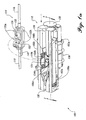
- FIGURE 1a displays an intravenous pump assembly 100 that senses the distal pressure and the proximal pressure in a pumping cassette 114 in order to detect an impediment to the flow of liquid in an IV line comprising a proximal tubing 116 and a distal tubing 118.
- Pumping cassette 114 which includes an elastomeric membrane 120. a port 133 and a flow stop 122, is connected to the IV line between proximal tubing 116 and distal tubing 118.
- a tang 142 disposed on the lower portion of the pumping cassette, at its distal end. facilitates positioning and guiding distal tubing 118 into a slot 126.
- Slot 126 is disposed at the distal end of a pump chassis 112. and the pumping cassette is inserted in the slot and engaged by the pump chassis.
- the interior of pump chassis 112 is adapted to engage pumping cassette 114 and position a reciprocating plunger 124 against the surface of elastomeric membrane 120.
- a prime mover or electric motor 136 is coupled to a linkage (not shown) that reciprocatively drives plunger 124 against elastomeric membrane 120 when the motor rotates a cam (not shown) that is coupled to the plunger.
- a pair of latches 110b are positioned within a pair of ports 134b that are disposed in a side wall of pump chassis 112. Although not shown in this Figure. a similar pair of latches 110a are positioned within a pair of ports 134a that are disposed in an opposite side wall of pump chassis 112.
- the pairs of latches 110a and 110b are fully extended from within respective ports 134a and 134b, so that the latches engage notches 132b. which are formed on the sides of pumping cassette 114, firmly holding the pumping cassette at a predetermined position within the pump chassis interior.
- pairs of latches 110a and 110b are retracted into their respective ports 134a and 134b. they disengage from pumping cassette 114. so that the pumping cassette may be removed from the interior of pump chassis 112.
- An elongate shaped member 108a extends generally parallel to the longitudinal axis of pump chassis 112. on one side thereof. and latches 110a are disposed on an inwardly facing surface of the member. Member 108a is pivotally connected to pump chassis 112 by a pair of hinges 103a that are disposed at opposed ends of the member's bottom edge. Similarly, an elongate shaped member 108b extends generally parallel to the longitudinal axis of pump chassis 112. at an opposite side of pump chassis 112 from member 108a. and pair of latches 110b are disposed on an inwardly facing surface of member 108b. which is pivotally connected to the pump chassis by a pair of hinges (not shown).
- a linkage (not shown) is coupled to members 108a and 108b and to a user actuated plunger 138.
- User actuated plunger 138 is disposed at a proximal end of pump chassis 112.
- the linkage to which it is coupled causes members 108a and 108b to pivot about their respective hinges, outwardly and away from the interior of the pump chassis, at both sides.
- latches 110a and 110b move (retract) through ports 134a and 134b. so that the latches are not extended into the interior of pump chassis 112.
- pumping cassette 114 is disposed in the interior of pump chassis 112 at the predetermined position. Members 108a and 108b are shown in the position in which the pumping cassette is engaged. Tans 142 is disposed within slot 126 and distal tubing 118 is positioned between ports 128a and 128b in the slot. Although not illustrated in this view. membrane 120 is in contact with plunger 124. so that reciprocation of the plunger forces medicinal liquid to flow through the pumping cassette when motor 136 is energized. Further. rod 106b is in contact with the portion of elastomeric membrane 120 that is accessed through port 133 and rod 106a is in contact with flow stop 122. which rides on top of another portion of the elastomeric membrane. When pumping cassette 114 is thus coupled to the pump chassis, very small distal and proximal pressures within the pumping cassette are transmitted through elastomeric membrane 120 and coupled to rods 106a and 106b.
- slot 130 is shown the proximal end of pump chassis 112 and slot 126 at the distal end of the pump chassis.
- Plunger 124 is positioned transversely to the interior of pump chassis 112. and pair of latches 110b are disposed inside the pair of ports 134b.
- Rod 106a is longitudinally disposed in a bore 105a that connects the interior of chassis 112 to a cavity 139a. Rod 106a is free to move in bore 105a. with one end of the rod disposed in the chassis interior and the other end disposed in cavity 139a.
- a keeper 140a is connected to the other end of rod 106a to prevent the rod falling through bore 105a into the interior of chassis 112.
- a leaf spring 102a is disposed transverse to rod 106a in cavity 139a. An end portion of leaf spring 102a is fixed to pump chassis 112 by a pair of threaded fasteners 144a. A free end of leaf spring 102a is cantilevered from pump chassis 112 and free to flex in a direction responsive to longitudinal movement of rod 106a. A rounded knob 104a is connected to the free end of leaf spring 102a at a position that is directly opposite the adjacent end of rod 106a.
- a strain gauge 128a is mounted on leaf spring 102a, at a middle portion of the leaf spring between its free end and its mounted end.
- Lead 146a is connected to strain gauge 128a and the other end is electrically connected to a controller 162 (not shown in this Figure).
- Lead 146a is employed to supply the excitation voltage for strain gauge 128a and convey a differential voltage to controller 162.
- a rod 106b is disposed in a bore 105b.
- An end of rod 106b is connected to a keeper 140b. which prevents the rod from slipping into the interior of the pump chassis through bore 105b.
- a leaf spring 102b is disposed in a cavity 139b and an end portion of the leaf spring is connected to pump chassis 112 by a pair of threaded fasteners 144b.
- a free end of leaf spring 102b is cantilevered from the pump chassis and is free to flex in a direction responsive to longitudinal movement of rod 106b.
- a rounded knob 104b is connected to the free end of the leaf spring. at a position opposite the adjacent end of rod 106b.
- a strain gauge 128b is mounted on a middle portion of leaf spring 102b, between its free end and its mounted end. and a lead 146b extends between the strain gauge and controller 162 (not shown here).
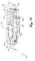
- FIGURE 3a depicts pumping cassette 1 14 (in phantom view) positioned adjacent to pump chassis 112, prior to engagement of the pumping cassette in the interior of the pump chassis.
- This Figure also shows how flow stop 122, elastomeric membrane 120. and elastomeric membrane 133 are aligned with rod 106a. plunger 124, and rod 106b, respectively.
- Flow stop 122 is illustrated in a closed position that disables free flow of a liquid through pumping cassette 114.
- the pairs of latches 110a and 110b are retracted within the pairs of ports 134a and 134b that are disposed in the side walls of pump chassis 112.
- rods 106a and 106b are not preloaded (pressed) against the surface of knobs 104a and 104b. respectively. Further. the free ends of leaf springs 102a and 102b are disposed opposite and extend substantially normal to rods 106a and 106b. respectively.
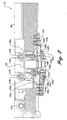
- FIGURE 3b illustrates pumping cassette 114 engaged in pump chassis 112 and shows how flow stop 122.
- elastomeric membrane 120. and the portion of the elastomeric membrane accessed through port 133 are engaged by rod 106a.
- plunger 124, and rod 106b respectively.
- Fluid pressure developed by plunger acting on the elastomeric membrane of pumping cassette 114 causes the flow stop to move to an open position. enabling the flow of liquid through the pumping cassette.
- FIGURE 4 the end of rod 106a is shown extended from bore 105a towards the interior of cavity 139a.
- This end of rod 106a has a flat surface 141a that is pressed against a rounded surface 145a of knob 104a.
- a rounded surface 147a is positioned adjacent. but apart from. a stop 143a, which limits the flexure travel of the free end of leaf spring 102a inside cavity 139a.
- the curvature of rounded surface 145a is provided to ensure that only normal forces are transmitted from rod 106a to leaf spring 102a.
- knob 104a is fabricated of a material that has an extremely low coefficient of friction such as DELRINTM plastic. Also.
- rod 106a is preferably fabricated of an alloy impregnated or coated with TEFLONTM plastic to reduce friction within bore 105a. and between flat surface 141 a and rounded surface 145a, It is desirable to only flex leaf spring 102a due to application of a normal force so that the differential voltage produced by strain gauge 128a more accurately reflects the actual pressure mechanically transmitted through the end of rod 106a in contact with flow stop 122.
- FIGURE 5 illustrates how the end of rod 106b extends from bore 105b into cavity 1396 so that a flat surface 141b on the rod contacts a rounded surface 145b on an end of knob 104b.
- a rounded surface 147b on the other end of the knob is adjacent. but spaced apart from a stop 143b. which serves to limit the flexure travel of the free end of leaf spring 102b within cavity 139b.
- the curve of rounded surface 145a minimizes transmission of non-normal force to leaf spring 102b.
- knob 104b and rod 106b are fabricated of materials that have a low coefficient of friction to reduce friction and minimize the transmission of non-normal forces.
- leaf spring 102b causes strain gauge 128b to produce a differential voltage that is indicative of the force applied to the end of rod 106b. which is in contact with the portion of elastomeric membrane 120 that is accessed through port 133, and is thus indicative of the pressure of the fluid acting on the opposite surface of the elastomeric membrane.
- the deflection of leaf spring 102a causes strain gauge 128a to produce a differential voltage that is indicative of the force applied to the end of rod 106a through flow stop 122. which is in contact with the portion of elastomeric membrane 120 that underlies the flow stop: this force is thus indicative of the pressure of the fluid acting on the opposite surface of this portion of the elastomeric membrane.
- a strain gauge 190 is illustrated. which is exemplary of a metal film resistor type that may be employed for strain gauges 128a and 128b.
- Strain gauge 190 includes an array of resistors 197 that are configured in a Wheatstone bridge circuit.
- a direct current (DC) supply 192 produces an excitation voltage that is applied to terminals 194a and 194b of the Wheatstone bridge.
- the resistance of at least one of resistors 197 varies with the stress applied thereto.
- the effect of varying the resistance of one or more of resistors 197 is to produce an imbalance in the Wheatstone bridge that causes a differential voltage across terminals 196a and 196b. This differential voltage is input to an amplifier 198 and amplified before it is supplied to controller 162.
- each leg of a semiconductor strain gauge bridge has an impedance that is a few thousand ohms and a current source is often used for excitation rather than a voltage source. to minimize temperature sensitivities.
- a preferred embodiment uses a semiconductorstrain gauge. As described in greater detail below, the present invention automates several of the calibration procedure steps for the output signal (differential voltage) produced by the semiconductor strain gauge as well as the metal film resistor strain gauge.
- the present invention monitors the proximal and distal fluid pressures inside pumping cassette 114 to detect an impediment to the flow of a liquid in the IV line in which the pumping cassette is installed.
- Port 133 provides access to a portion of elastomeric membrane 120 at the proximal side of pumping cassette 114.
- Proximal fluid pressure inside pumping cassette 114 exerts a force on the elastomeric membrane that is mechanically transmitted through rod 106b to leaf spring 102b and strain gauge 128b.
- the output signal of strain gauge 128b is amplified and applied to an analog to digital conversion (ADC) input of controller 162.
- ADC analog to digital conversion
- Controller 162 employs the ADC input to provide a digital signal corresponding to the proximal fluid pressure inside pumping cassette 114.
- the distal fluid pressure inside pumping cassette 114 is similarly measured. except that rod 106a is in contact with flow stop 122 and through the flow stop, in contact with the portion of the elastomeric membrane of the pumping cassette exposed to the distal fluid pressure of the IV line. In all other regards. the distal pressure is sensed in the same manner as the proximal pressure.
- the present invention also automates the output calibration steps for the proximal and distal pressures.
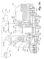
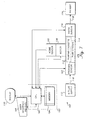
- FIGURE 7 an overview block diagram 160 of the medicinal fluid infusion system illustrates the control system for a proximal pressure sensor 182 and a distal pressure sensor 176.
- Proximal pressure sensor 182 and distal pressure sensor 176 include the components discussed above for producing output signals that are indicative of the respective proximal and distal pressures within pumping cassette 114.
- An intravenous medicinal liquid supply 172 is connected to proximal tubing 116 and supplies a medicinal liquid to pumping cassette 114, which is latched into pump chassis 112.
- Motor 136 is drivingly coupled to pumping cassette 114 so that the medicinal liquid may be administered to a patient 174 through distal tubing 118.
- a home position of a drive shaft (not shown) of motor 136 in the pumping cycle of pumping cassette 114 is detected by a home sensor 180 that is coupled to controller 162. which includes a central processing unit (CPU) 166 and a memory 164.
- Memory 164 stores a plurality of machine instructions that when executed by CPU 166. caused a plurality of functions to be implemented. Among the plurality of functions are the logical steps discussed below for calibration and monitoring proximal and distal pressures to detect a hindrance in the flow of the medicinal liquid through the IV line.
- the system also includes a display 170 and a user interface 168. e.g., a keypad. which are connected to controller 162 to provide an interface for the user.
- the IV pump may be coupled to a personal computer. so that the input device can include a mouse or other pointing device.
- home sensor 180 is an optical encoder coupled to the drive shaft of motor 136 for detecting a home position of the drive shaft.
- each pump stroke infuses 75 micro liters ( ⁇ l) of liquid and is divided into 432 pulses (216 pulses for fill and 216 pulses for flow). The large number of pulses enables a high level of precision in delivery of the medicinal liquid and reduces the likelihood of needle clotting in the patient's body.
- proximal pressure sensor 182 and distal pressure sensor 176 Power consumption of the IV pump is reduced by supplying power to proximal pressure sensor 182 and distal pressure sensor 176 only when motor 136 is energized.
- controller 162 When controller 162 energizes proximal pressure sensor 182 and distal pressure sensor 176, approximately 1.5 milliseconds of warm up time are required before the sensor signals may be sampled. Also. controller 162 periodically checks the sampled signal from proximal pressure sensor 182 for a false low during the delivery of the medicinal liquid to the patient. so that an empty medical liquid supply 172 may be quickly detected. Furthermore. the logic discussed in detail below reduces false occlusion alarms by comparing/averaging two or more sampled signals. In this way. signal samples taken during minor pumping irregularities and occasional signal spikes do not trigger a false occlusion alarm.
- the sampling time interval begins when valves (not shown) in pumping cassette 114 open and the interval ends when the valves close.
- controller 162 may not sample proximal pressure sensor 182 during the delivery stroke and distal pressure sensor 176 may not be sampled during the intake stroke.
- the disposition of the valves in pumping cassette 114 are inferred from the position of the drive shaft of motor 136. which is sensed by home sensor 180.
- the standard sampling rate is approximately four samples per delivery stroke (e.g., at 30 millisecond intervals when delivering fluid at 1000 ml/hr). which is often enough to enable motor 136 to be de-energized before achieving a pressure of 40 psig at the distal end of pumping cassette 114.
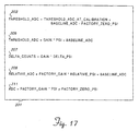
- a table 201 lists equations employed by controller 162 to determine an occlusion in the IV line.
- a threshold_adc equation 203 is used to calculate an ADC value that is a function of a threshold pressure, a baseline pressure and a factory zero pressure.
- a threshold_adc equation 205 is employed to calculate the corresponding ADC value for any relative pressure value that is not one of the calibration values (e.g., 5 psig relative).
- a delta_counts equation 207 is used to calculate the ADC counts corresponding to any delta pressure.
- a relative_adc equation 209 converts a relative pressure to its corresponding ADC value.
- An adc equation 211 is employed to convert an absolute pressure value to its ADC value.
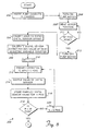
- FIGURES 8 and 9. an overview 200 illustrates the steps employed at the factory to calibrate distal pressure sensor 176 and proximal pressure sensor 182 before the pump chassis (in its housing - not shown) is shipped to the end user to be used for infusing a medicinal liquid into a patient.
- the term "user” is intended to apply to the factory calibration operator - not the end user of the pump for medical applications. Also. in this and the other flow charts discussed below, it will be understood that the logical steps shown are implemented by CPU 166 in controller 162 when executing machine instructions that are stored in memory 164.
- a block 202 in which pumping cassette 114 is inserted in pump chassis 112.
- the pump motor is turned on in a block 208, and the plunger is moved to a halfway extended position.
- a block 209 provides for reading the position of the motor (shaft). and a decision block 211 loops until the motor position is 90o past its home position. which corresponds to the halfway extension of the plunger. Once this condition is achieved.
- a block 213 indicates that the pump motor is de-energized.
- the logic prompts a user to provide an offset value for distal pressure sensor 176. The logic proceeds to a block 206.
- Controller 162 adjusts the impedance of an electronically variable resistor (not shown) to correspond to the offset value provided by the user.
- N is set equal to zero. and the logic advances to a block 212.
- a prompt is displayed to indicate that the user should apply N psig to the distal port of the pumping cassette to calibrate distal pressure sensor 176 (and press a control key on the keypad to indicate that the requested pressure has been applied to the distal pressure sensor).
- the output from distal pressure sensor 176 is sampled and monitored by the controller.
- the sampled distal sensor value for N psig is stored.
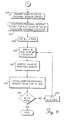
- proximal pressure sensor 182 If the determination at decision block 218 is true. the logic flows to a block 222 and the user is prompted to enter an eight bit offset value for proximal pressure sensor 182, as illustrated in FIGURE 9.
- the output of proximal pressure sensor 182 is calibrated to an ADC value of 125 by the user adjusting the impedance of a variable resistor (not shown) to obtain a display of the user input offset value.
- M is set equal to -5 psig, and the logic flows to a block 228. The logic produces a prompt that indicates that pressure of M psig is to be applied by the user to the proximal port of the pumping cassette to be sensed by proximal pressure sensor 182.
- the output from proximal pressure sensor 182 is sampled at M psig.
- the reading of the output of proximal pressure sensor 182 is stored as a proximal calibration threshold value corresponding to the current value of M psig.
- a determination is made as to whether M is equal to 0. If false. the logic advances to a block 236 and M is set equal to M plus five psig. The logic then loops back to block 228. where the user is instructed to apply zero psig to the proximal port of the pumping cassette. The steps in blocks 230. 232. and decision block 234 are then repeated.
- M will not equal zero. and the calibration procedure terminates. Proximal threshold calibration values corresponding to -5 and 0 psig will have been stored.
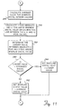
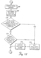
- an overview 290 includes the steps employed to detect an occlusion with distal pressure sensor 176. Note that any mention of "user” in regard to the description of FIGURES 10-15 refers to the end user of the invention. who is infusing a medicinal liquid into a patient.
- the logic determines if distal pressure sensor 176 is energized and pumping cassette 114 is latched in the predetermined position within the interior of pump chassis 112. The logic will loop until the determination is true and then advance to a block 240. in which a distal baseline value is reset (or set) equal to zero. The distal baseline value is calculated by averaging the two previous output signals that were sampled from distal pressure sensor 176 when the shaft (not shown) of motor 136 is in the home position. At a decision block 242. the logic determines if the shaft of motor 136 is rotating and loops until the determination is affirmative.
- a block 244 two consecutive samples of the output signal from distal pressure sensor 176 are sampled.
- the logic at a decision block 246 determines if the last sample is more than 2 psig greater than the previous sample. If true. the logic flows to a block 250. and the last sample is discarded. In a block 252. the output signal for distal pressure sensor 176 is sampled at the next home position for the shaft of pump motor 136. The logic will continue looping back to decision block 246 until the last sample is within 2 psig of the previous sample being compared.
- the logic advances to a decision block 248 to determine if a check_cassette flag was set during the two samplings of the output signal from distal pressure sensor 176. If true. the logic loops back to block 244. and two new consecutive samples of the output signal from distal pressure sensor 176 will be obtained. However, if the determination is false at decision block 248, the logic steps to a block 254 (FIGURE 11) and calculates an average distal value for the last two consecutively sampled output signals from distal pressure sensor 176.
- the logic determines an absolute value of 4 psig and a value 2 psig above the lowest output signal sampled from distal pressure sensor 176 since pumping cassette 114 was latched into pump chassis 112.
- the 2 and 4 psig values are determined relative to a calibration line extending between the stored distal calibration threshold values for 0 and 12 psig.
- the logic determines the lesser value of the 4 psig absolute value and the other value determined in block 256.
- a decision block 260 determines if the lesser value is less than the averaged distal value determined in block 254. If affirmative, the distal baseline value is set equal to the lesser value. and the logic advances to a block 266 (in FIGURE 12). If the determination at decision block 260 is negative. the logic moves to a block 262, and the distal baseline value is set equal to the averaged distal value.
- the output signal from distal pressure sensor 176 is sampled.
- the equations that are illustrated in FIGURE 17 are employed for calculating the relative distal pressure value.
- the user can select one of three sensitivities to be applied when detecting a distal occlusion alarm. corresponding to a HIGH. MEDIUM, and LOW pressure.
- the LOW distal pressure selection provides for a threshold of 6 psig. with a tolerance of ⁇ 3 psig.
- the MEDIUM distal pressure selection provides for a threshold of 12 psig. with a tolerance of ⁇ 5 psig.
- the HIGH distal pressure selection provides for a threshold of 24 psig, with a tolerance of ⁇ 5 psig.
- a decision block 270 determines whether the relative distal pressure value for three consecutive samplings are each greater than the threshold value for the selected sensitivity range. If true. the logic steps to a block 276. and an occlusion alarm flag is set on. At a block 278. the occlusion alarm is displayed to the user. and the logic steps to a decision block 280 (in FIGURE 13). However. if at decision block 270. the determination was false, the logic advances to a decision block 274 to determine if the absolute value of the distal pressure signal exceeds 30 psig. If affirmative, the logic flows back to block 276, and if negative, the logic proceeds to decision block 280 in FIGURE 13.
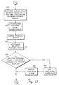
- FIGURES 14-16 show an overview 300 of the steps employed to detect an occlusion with proximal pressure sensor 182.
- the logic determines if proximal pressure sensor 182 is energized and pumping cassette 114 is latched in the predetermined position within pump chassis 112. The logic continues in a loop at decision block 302 until the determination is true and then advances to a block 304.
- This block provides for resetting (or setting) a proximal baseline value equal to zero.
- the proximal baseline value is the average of the two prior output signals from proximal pressure sensor 182 that have been sampled when the shaft (not shown) of pump motor 136 is in the position corresponding to the full extension of the plunger.
- the logic determines if the shaft of motor 136 is rotating and loops until the determinationat decision block 306 is affirmative.
- a block 308 two consecutive samples of the output signal from proximal pressure sensor 182 are sampled (with the plunger fully extended). The logic at a decision block 310 then determines whether last sample from proximal pressure sensor 182 is more than 2 psig lower than the previous sample. If affirmative. the logic flows to a block 314 and the last sample is discarded. Advancing to a block 316. the output signal for proximal pressure sensor 182 is sampled at the next position for the shaft of pump motor 136 at which the plunger is fully extended. The logic continues looping back to decision block 310 until two samples are obtained that are within 2 psig of each other.
- the logic advances to a decision block 312 to determine if the check_cassette flag was set during the sampling of the output signal from proximal pressure sensor 182. If affirmative. the logic loops back to block 308, so that two new consecutive samples are obtained from proximal pressure sensor 182. However, if the determination is negative at decision block 312, the logic advances to a block 318 (FIGURE 15) in which the lesser of an absolute value of -2 psig and a value that is 2 psig below the highest output signal sampled from proximal pressure sensor 182 since pumping cassette 114 was latched into pump chassis 112 is determined.
- -2 and 2 psig values are determined relative to a calibration line that extends between the stored proximal calibration threshold value for -5 psig and 0 psig.
- the logic moves to a block 320 in which the proximal baseline value is set equal to the sample that has the lesser value identified in block 318.
- the output signal from proximal pressure sensor 182 is sampled and the logic steps to a block 324.
- the logic then employs the equations described in FIGURE 17 to calculate the relative proximal pressure value.
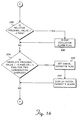
- the logic decides whether the relative proximal pressure values for three consecutive samplings are all greater than the threshold value (relative to a calibration line produced with the stored proximal calibration threshold values). The allowed tolerance for this determination in the preferred embodiment is ⁇ 3 psis. If true.
- a block 328 indicates that the occlusion flag is set on. Next. the occlusion alarm is displayed to the user in a block 330.
- the logic advances to a decision block 332. as shown in FIGURE 16. This decision block determines if the relative proximal pressure value is greater than -2 psig. and if so. the logic jumps to a block 336 in which the occlusion flag is set off or cleared. The logic next advances to a decision block 334 from block 336 or if the determination at decision block 332 is false. Decision block 334 determines if the absolute proximal pressure values for two consecutive samplings are less than -10 psig or greater than 5 psig. which may indicate that the pumping cassette has been removed. If true. the logic advances to a block 338 and the check_cassette flag is set on. At a block 340, the check_cassette alarm is displayed to the user. The logic returns to block 308 (in FIGURE 14) from block 340 or if the determination at decision block 334 is false.
Abstract
Description
Claims (12)
- A system (100) for detecting an impediment to a fluid flow through an intravenous line, comprising:(a) a pump chassis (112);(b) a pump (114) in fluid communication with the intravenous line and mountable within the pump chassis (112) to receive a driving force, said pump (114) including a proximal port (133), a distal port (122), and an elastomeric membrane (120) overlying a fluid path through the pump (114) adjacent the proximal port (133) and distal port (122);(c) a proximal pressure sensor (182) mounted on the pump chassis (112) and including a member (106b) that is coupled to the elastomeric membrane (120) adjacent to the proximal port (133) of the pump (114) and responsive to a deflection and force exerted by the elastomeric membrane (120) due to a proximal fluid pressure within the pump (114), producing a proximal pressure signal indicative thereof;(d) a distal pressure sensor (176) mounted on the pump chassis (112) and including a member (106a) that is coupled to the elastomeric membrane (120) adjacent to the distal port (122) of the pump (114) and responsive to a deflection and force exerted by the elastomeric membrane (120) due to a distal fluid pressure within the pump (114), producing a distal pressure signal indicative thereof; and(e) a controller (162) that is electrically coupled to the proximal pressure sensor (182) and the distal pressure sensor (176) to receive the proximal and distal pressure signals, the controller (162) including:characterized in that said controller (162) employs the proximal pressure signal to determine a baseline proximal pressure and an absolute proximal pressure, and employs the distal pressure signal to determine a baseline distal pressure and an absolute distal pressure, and determines whether an impediment to fluid flow through the intravenous line has occurred as a function of the baseline proximal pressure, the baseline distal pressure, the absolute proximal pressure, and the absolute distal pressure, said logical steps including:(i) a processor (166);(ii) a user interface (168) that permits entry of data by a user;(iii) a display (170) for displaying prompts and information to a user; and(iv) a memory (164) that is coupled to the processor (166), the memory (164) storing a plurality machine instructions that cause the processor (166) to perform a plurality of logical steps when the machine instructions are executed by the processor (166),(i) enabling calibration of the proximal pressure sensor (182) and the distal pressure sensor (176) before the pump (114) is initially placed into operation to pump (114) the fluid, said calibration storing a proximal offset, a distal offset, and calibration threshold values for the proximal pressure sensor (182) and the distal pressure sensor (176) in the memory (164); and(ii) when the pump (114) is placed into operation to pump the fluid, sampling the proximal pressure signal produced by the proximal pressure sensor (182) and the distal pressure signal produced by the distal pressure sensor (176) to determine the baseline proximal pressure and the baseline distal pressure, respectively, using the proximal offset and the distal offset and the calibration threshold values.
- The system (100) of claim 1, wherein the pump (114) comprises a pumping cassette, the pump chassis (112) latching the pumping cassette in a predetermined position within the pump chassis (112) before the controller (162) begins monitoring the proximal pressure and the distal pressure.
- The system (100) of claim 2, wherein latching the pumping cassette in the pump chassis (112) applies a preload force from the elastomeric membrane (120) directed against the proximal pressure sensor (182) and against the distal pressure sensor (176) through their respective members, said preload force tending to stabilize a zero proximal pressure signal and a zero distal pressure signal.
- The system (100) of claim 2, wherein the proximal pressure sensor (182) and the distal pressure sensor (176) each comprise:(a) a beam having an end rigidly connected to the pump chassis (112) and a free end that flexes in response to a force applied by the member (106b, 106a); and(b) a strain gauge mounted on the beam, said strain gauge responding to a flexure of the beam by producing an output signal indicative of one of the proximal and the distal pressures.
- The system (100) of claim 4, wherein the member (106b, 106a) of each of the proximal and distal pressure sensors comprises an elongate rod that is movable along a longitudinal axis of the rod within an orifice that is disposed in the pump chassis (112), in response to a force exerted by the fluid within the pumping cassette against the elastomeric membrane (120), said force being a function of a fluid pressure.
- The system (100) of claim 5, wherein each rod is impregnated with at least one material selected to substantially reduce friction between the rod and the orifice in the pump chassis (112) through which the rod moves.
- The system (100) of claim 5, where each beam includes a knob mounted on the free end thereof, adjacent to an end of the rod, at least one of the end of the rod and an end of the knob that contacts the end of the rod including a surface having a curvature selected to isolate the beam from any forces by the rod that are not directed generally in parallel with the longitudinal axis of the rod.
- The system (100) of claim 7, wherein each knob is fabricated of a material selected because of its low coefficient of friction, to minimize an effect of forces applied to the knob by the rod that are not susbtantially normal to the beam.
- The system (100) of claim 7, wherein the rod of the distal pressure sensor contacts a flow stop disposed on the pumping cassette, the flow stop being disposed adjacent to and in contact with a portion of the elastomeric membrane (120) within the pumping cassette.
- The system (100) of claim 9, wherein the flow stop is pivotally mounted on the pumping cassette to pivot between an open position in which the flow stop permits a flow of fluid through the pumping cassette and transmits a force from the elastomeric membrane (120) to the rod of the distal pressure sensor that corresponds to the distal pressure, and a closed position in which the flow stop interrupts a free flow of the fluid through the pumping cassette, the rod of the distal pressure sensor automatically moving the flow stop to the open position when the pumping cassette is latched into the chassis.
- The system (100) of claim 1, wherein the controller (162) further includes an analog-to-digital converter that converts the proximal pressure signal to a corresponding digital value and the distal pressure signal to a corresponding digital value.
- The system (100) of claim 1, wherein the processor (166) executes the further step of producing an occlusion alarm on the display (170) if samples of the proximal pressure signal or the distal pressure signal indicate that the impediment to the fluid flow has occurred.
Applications Claiming Priority (3)
| Application Number | Priority Date | Filing Date | Title |
|---|---|---|---|
| US97062 | 1998-06-12 | ||
| US09/097,062 US5989222A (en) | 1998-06-12 | 1998-06-12 | Pressure (occlusion) sensor |
| PCT/US1999/013016 WO1999064091A2 (en) | 1998-06-12 | 1999-06-11 | Occlusion detection system |
Publications (2)
| Publication Number | Publication Date |
|---|---|
| EP1083950A2 EP1083950A2 (en) | 2001-03-21 |
| EP1083950B1 true EP1083950B1 (en) | 2005-10-19 |
Family
ID=22260725
Family Applications (1)
| Application Number | Title | Priority Date | Filing Date |
|---|---|---|---|
| EP99931780A Expired - Lifetime EP1083950B1 (en) | 1998-06-12 | 1999-06-11 | Occlusion detection system |
Country Status (9)
| Country | Link |
|---|---|
| US (1) | US5989222A (en) |
| EP (1) | EP1083950B1 (en) |
| JP (1) | JP4141639B2 (en) |
| AT (1) | ATE306956T1 (en) |
| AU (1) | AU765163B2 (en) |
| CA (1) | CA2334477C (en) |
| DE (1) | DE69927811T2 (en) |
| ES (1) | ES2251203T3 (en) |
| WO (1) | WO1999064091A2 (en) |
Families Citing this family (58)
| Publication number | Priority date | Publication date | Assignee | Title |
|---|---|---|---|---|
| US7621893B2 (en) | 1998-10-29 | 2009-11-24 | Medtronic Minimed, Inc. | Methods and apparatuses for detecting occlusions in an ambulatory infusion pump |
| US7766873B2 (en) | 1998-10-29 | 2010-08-03 | Medtronic Minimed, Inc. | Method and apparatus for detecting occlusions in an ambulatory infusion pump |
| US6077055A (en) * | 1998-12-03 | 2000-06-20 | Sims Deltec, Inc. | Pump system including cassette sensor and occlusion sensor |
| US6497680B1 (en) * | 1999-12-17 | 2002-12-24 | Abbott Laboratories | Method for compensating for pressure differences across valves in cassette type IV pump |
| US7902679B2 (en) * | 2001-03-05 | 2011-03-08 | Megica Corporation | Structure and manufacturing method of a chip scale package with low fabrication cost, fine pitch and high reliability solder bump |
| US6893414B2 (en) * | 2002-08-12 | 2005-05-17 | Breg, Inc. | Integrated infusion and aspiration system and method |
| US7258534B2 (en) * | 2003-09-22 | 2007-08-21 | Hospira, Inc. | Fluid delivery device identification and loading system |
| US7206715B2 (en) * | 2003-12-31 | 2007-04-17 | Cardinal Health 303, Inc. | Empty container detection using container side pressure sensing |
| DK1818664T3 (en) * | 2006-02-13 | 2013-08-05 | Hoffmann La Roche | Apparatus for recognizing a pressure change in the liquid path of a micro-dosing device |
| US8167832B2 (en) | 2006-12-09 | 2012-05-01 | The Alfred E. Mann Foundation For Scientific Research | Ambulatory infusion devices and methods including occlusion monitoring |
| US8062008B2 (en) | 2007-09-27 | 2011-11-22 | Curlin Medical Inc. | Peristaltic pump and removable cassette therefor |
| US7934912B2 (en) | 2007-09-27 | 2011-05-03 | Curlin Medical Inc | Peristaltic pump assembly with cassette and mounting pin arrangement |
| US8083503B2 (en) | 2007-09-27 | 2011-12-27 | Curlin Medical Inc. | Peristaltic pump assembly and regulator therefor |
| DE102007048880B4 (en) * | 2007-10-11 | 2009-07-30 | Up Management Gmbh | A sphygmomanometer and method of operating a sphygmomanometer |
| US9026370B2 (en) | 2007-12-18 | 2015-05-05 | Hospira, Inc. | User interface improvements for medical devices |
| US7867192B2 (en) * | 2008-02-29 | 2011-01-11 | The Alfred E. Mann Foundation For Scientific Research | Ambulatory infusion devices and methods with blockage detection |
| US7927306B2 (en) * | 2008-06-26 | 2011-04-19 | Calibra Medical, Inc. | Disposable infusion device with prime indicator |
| US8378837B2 (en) * | 2009-02-20 | 2013-02-19 | Hospira, Inc. | Occlusion detection system |
| CA2769030C (en) | 2009-07-30 | 2016-05-10 | Tandem Diabetes Care, Inc. | Infusion pump system with disposable cartridge having pressure venting and pressure feedback |
| WO2011011814A1 (en) * | 2009-07-30 | 2011-02-03 | Acu Rate Pty Limited | An administration set flow condition monitor |
| FR2959224A1 (en) * | 2010-04-23 | 2011-10-28 | Commissariat Energie Atomique | METHOD FOR DRAINING A COLLABABLE RESERVOIR |
| JP5728632B2 (en) * | 2010-08-06 | 2015-06-03 | 株式会社テクトロン | Method for calibrating occlusion pressure in medical liquid pump and medical liquid pump |
| AU2011308700B2 (en) | 2010-10-01 | 2015-04-02 | Zevex, Inc. | Pressure sensor seal and method of use |
| US9067003B2 (en) * | 2011-05-26 | 2015-06-30 | Kalypto Medical, Inc. | Method for providing negative pressure to a negative pressure wound therapy bandage |
| DK2729200T3 (en) * | 2011-07-06 | 2017-01-02 | Hoffmann La Roche | AUTOMATIC INJECTION DEVICE INCLUDING TWO OCCLUSION SENSORS |
| US9240002B2 (en) | 2011-08-19 | 2016-01-19 | Hospira, Inc. | Systems and methods for a graphical interface including a graphical representation of medical data |
| US10022498B2 (en) | 2011-12-16 | 2018-07-17 | Icu Medical, Inc. | System for monitoring and delivering medication to a patient and method of using the same to minimize the risks associated with automated therapy |
| AU2013239778B2 (en) | 2012-03-30 | 2017-09-28 | Icu Medical, Inc. | Air detection system and method for detecting air in a pump of an infusion system |
| US9180242B2 (en) | 2012-05-17 | 2015-11-10 | Tandem Diabetes Care, Inc. | Methods and devices for multiple fluid transfer |
| WO2013177379A1 (en) | 2012-05-25 | 2013-11-28 | Smiths Medical Asd, Inc. | Occlusion detection |
| CA3089257C (en) | 2012-07-31 | 2023-07-25 | Icu Medical, Inc. | Patient care system for critical medications |
| US9173998B2 (en) | 2013-03-14 | 2015-11-03 | Tandem Diabetes Care, Inc. | System and method for detecting occlusions in an infusion pump |
| AU2014268355B2 (en) | 2013-05-24 | 2018-06-14 | Icu Medical, Inc. | Multi-sensor infusion system for detecting air or an occlusion in the infusion system |
| CA2913915C (en) | 2013-05-29 | 2022-03-29 | Hospira, Inc. | Infusion system which utilizes one or more sensors and additional information to make an air determination regarding the infusion system |
| CA2913918C (en) | 2013-05-29 | 2022-02-15 | Hospira, Inc. | Infusion system and method of use which prevents over-saturation of an analog-to-digital converter |
| US20150133861A1 (en) | 2013-11-11 | 2015-05-14 | Kevin P. McLennan | Thermal management system and method for medical devices |
| US20150182698A1 (en) | 2013-12-31 | 2015-07-02 | Abbvie Inc. | Pump, motor and assembly for beneficial agent delivery |
| ES2776363T3 (en) | 2014-02-28 | 2020-07-30 | Icu Medical Inc | Infusion set and method using dual wavelength in-line optical air detection |
| AU2015266706B2 (en) | 2014-05-29 | 2020-01-30 | Icu Medical, Inc. | Infusion system and pump with configurable closed loop delivery rate catch-up |
| US10227971B2 (en) * | 2014-08-12 | 2019-03-12 | Kpr U.S., Llc | Downstream flow detection system for flow control apparatus |
| US10143795B2 (en) | 2014-08-18 | 2018-12-04 | Icu Medical, Inc. | Intravenous pole integrated power, control, and communication system and method for an infusion pump |
| US11344668B2 (en) | 2014-12-19 | 2022-05-31 | Icu Medical, Inc. | Infusion system with concurrent TPN/insulin infusion |
| CN104606737A (en) * | 2015-01-23 | 2015-05-13 | 深圳市科曼医疗设备有限公司 | Infusion pump and infusion pump blockage detecting method |
| US10850024B2 (en) | 2015-03-02 | 2020-12-01 | Icu Medical, Inc. | Infusion system, device, and method having advanced infusion features |
| ES2809505T3 (en) | 2015-05-26 | 2021-03-04 | Icu Medical Inc | Disposable infusion fluid delivery device for programmable delivery of high volume drugs |
| WO2016205584A1 (en) | 2015-06-17 | 2016-12-22 | Smiths Medical Asd, Inc. | Force sensing devices, systems and method for syringe pumps |
| JP7091240B2 (en) | 2015-09-25 | 2022-06-27 | シー・アール・バード・インコーポレーテッド | Catheter assembly including monitoring capability |
| US10300195B2 (en) | 2016-01-20 | 2019-05-28 | Medallion Therapeutics, Inc. | Ambulatory infusion devices and associated methods |
| WO2017146809A1 (en) | 2016-02-25 | 2017-08-31 | Massachusetts Institute Of Technology | Directional force sensing element and system |
| AU2017264784B2 (en) | 2016-05-13 | 2022-04-21 | Icu Medical, Inc. | Infusion pump system and method with common line auto flush |
| EP3468635A4 (en) | 2016-06-10 | 2019-11-20 | ICU Medical, Inc. | Acoustic flow sensor for continuous medication flow measurements and feedback control of infusion |
| US10089055B1 (en) | 2017-12-27 | 2018-10-02 | Icu Medical, Inc. | Synchronized display of screen content on networked devices |
| WO2020072234A1 (en) * | 2018-10-03 | 2020-04-09 | Baxalta GmbH | Detection assemblies for infusion pumps |
| KR102212231B1 (en) * | 2019-03-07 | 2021-02-03 | 부산대학교 산학협력단 | Drug release estimation method for drug infusion pump and investigation device for drug infusion pump thereof |
| US11278671B2 (en) | 2019-12-04 | 2022-03-22 | Icu Medical, Inc. | Infusion pump with safety sequence keypad |
| AU2021311443A1 (en) | 2020-07-21 | 2023-03-09 | Icu Medical, Inc. | Fluid transfer devices and methods of use |
| US11135360B1 (en) | 2020-12-07 | 2021-10-05 | Icu Medical, Inc. | Concurrent infusion with common line auto flush |
| US20230122601A1 (en) * | 2021-10-18 | 2023-04-20 | Becton, Dickinson And Company | Self-Calibration for Pump Operation of Medical Injector |
Family Cites Families (20)
| Publication number | Priority date | Publication date | Assignee | Title |
|---|---|---|---|---|
| US554115A (en) * | 1896-02-04 | Perfuming device | ||
| US4482347A (en) * | 1982-08-12 | 1984-11-13 | American Hospital Supply Corporation | Peristaltic fluid-pumping apparatus |
| US4690673A (en) * | 1985-11-26 | 1987-09-01 | Imed Corporation | Dual mode I.V. infusion device with distal sensor |
| US4784576A (en) * | 1986-09-02 | 1988-11-15 | Critikon, Inc. | Pump pressure sensor |
| US4882575A (en) * | 1987-01-28 | 1989-11-21 | Sharp Kabushiki Kaisha | Monitor for blocked condition in tube for fluid infusion pump |
| US4950244A (en) * | 1987-05-01 | 1990-08-21 | Abbott Laboratories | Pressure sensor assembly for disposable pump cassette |
| US4927411A (en) * | 1987-05-01 | 1990-05-22 | Abbott Laboratories | Drive mechanism for disposable fluid infusion pumping cassette |
| US4863425A (en) * | 1987-12-04 | 1989-09-05 | Pacesetter Infusion, Ltd. | Patient-side occlusion detection system for a medication infusion system |
| US4979940A (en) * | 1988-03-08 | 1990-12-25 | Baxter International Inc. | Infusion system, methodology, and algorithm for identifying patient-induced pressure artifacts |
| US5246347A (en) * | 1988-05-17 | 1993-09-21 | Patients Solutions, Inc. | Infusion device with disposable elements |
| US5116203A (en) * | 1990-03-15 | 1992-05-26 | Abbott Laboratories | Detecting occlusion of proximal or distal lines of an IV pump |
| JPH06501870A (en) * | 1991-06-10 | 1994-03-03 | バクスター、インターナショナル、インコーポレイテッド | Intravenous metering monitoring device |
| EP0519765B1 (en) * | 1991-06-21 | 1997-10-08 | Minimed Inc., doing business as Minimed Technologies | Implantable medication infusion pump including self-contained acoustic fault detection apparatus |
| US5213573A (en) * | 1991-08-05 | 1993-05-25 | Imed Corporation | Iv administration set infiltration monitor |
| US5292306A (en) * | 1993-01-29 | 1994-03-08 | Abbott Laboratories | Method of detecting occlusions in a solution pumping system |
| ES2202365T3 (en) * | 1994-05-13 | 2004-04-01 | Abbott Laboratories | HOUSING WITH DISPOSABLE LIQUID PERFUSION PUMPING CAMERA EQUIPPED WITH A FLUID SWITCH WITH PUSH BUTTON. |
| US5695473A (en) * | 1994-07-27 | 1997-12-09 | Sims Deltec, Inc. | Occlusion detection system for an infusion pump |
| US5554115A (en) * | 1995-04-07 | 1996-09-10 | Abbott Laboratories | Sensor for measuring pressures in a cassette pump proximal and distal to a pumping chamber |
| US5514102A (en) * | 1995-05-05 | 1996-05-07 | Zevex Incorporated | Pressure monitoring enteral feeding system and method |
| GB2338752B (en) * | 1996-04-10 | 2000-07-19 | Baxter Int | Volumetric infusion pump |
-
1998
- 1998-06-12 US US09/097,062 patent/US5989222A/en not_active Expired - Lifetime
-
1999
- 1999-06-11 AT AT99931780T patent/ATE306956T1/en not_active IP Right Cessation
- 1999-06-11 AU AU48212/99A patent/AU765163B2/en not_active Ceased
- 1999-06-11 DE DE69927811T patent/DE69927811T2/en not_active Expired - Lifetime
- 1999-06-11 JP JP2000553158A patent/JP4141639B2/en not_active Expired - Fee Related
- 1999-06-11 ES ES99931780T patent/ES2251203T3/en not_active Expired - Lifetime
- 1999-06-11 CA CA002334477A patent/CA2334477C/en not_active Expired - Fee Related
- 1999-06-11 EP EP99931780A patent/EP1083950B1/en not_active Expired - Lifetime
- 1999-06-11 WO PCT/US1999/013016 patent/WO1999064091A2/en active IP Right Grant
Also Published As
| Publication number | Publication date |
|---|---|
| DE69927811T2 (en) | 2006-07-20 |
| ATE306956T1 (en) | 2005-11-15 |
| AU765163B2 (en) | 2003-09-11 |
| CA2334477A1 (en) | 1999-12-16 |
| EP1083950A2 (en) | 2001-03-21 |
| WO1999064091A3 (en) | 2000-03-02 |
| WO1999064091A2 (en) | 1999-12-16 |
| US5989222A (en) | 1999-11-23 |
| CA2334477C (en) | 2008-01-08 |
| JP2002517288A (en) | 2002-06-18 |
| DE69927811D1 (en) | 2005-11-24 |
| JP4141639B2 (en) | 2008-08-27 |
| AU4821299A (en) | 1999-12-30 |
| ES2251203T3 (en) | 2006-04-16 |
Similar Documents
| Publication | Publication Date | Title |
|---|---|---|
| EP1083950B1 (en) | Occlusion detection system | |
| US6648861B2 (en) | Occlusion detection method and system for ambulatory drug infusion pump | |
| CA2334295C (en) | Air bubble sensor | |
| US5695473A (en) | Occlusion detection system for an infusion pump | |
| EP0225158B1 (en) | Dual mode i.v. infusion device | |
| US9433733B2 (en) | Methods and apparatuses for detecting occlusions in an ambulatory infusion pump | |
| US6422057B1 (en) | Drug pump testing system and methods | |
| US5213573A (en) | Iv administration set infiltration monitor | |
| US4617014A (en) | Dual mode I. V. infusion device | |
| EP0248633A2 (en) | Detection of fluid flow faults in the parenteral administration of fluids |
Legal Events
| Date | Code | Title | Description |
|---|---|---|---|
| PUAI | Public reference made under article 153(3) epc to a published international application that has entered the european phase |
Free format text: ORIGINAL CODE: 0009012 |
|
| 17P | Request for examination filed |
Effective date: 20001212 |
|
| AK | Designated contracting states |
Kind code of ref document: A2 Designated state(s): AT BE CH CY DE DK ES FI FR GB GR IE IT LI LU NL PT SE |
|
| 17Q | First examination report despatched |
Effective date: 20031021 |
|
| RAP1 | Party data changed (applicant data changed or rights of an application transferred) |
Owner name: HOSPIRA, INC. |
|
| GRAP | Despatch of communication of intention to grant a patent |
Free format text: ORIGINAL CODE: EPIDOSNIGR1 |
|
| GRAS | Grant fee paid |
Free format text: ORIGINAL CODE: EPIDOSNIGR3 |
|
| GRAA | (expected) grant |
Free format text: ORIGINAL CODE: 0009210 |
|
| AK | Designated contracting states |
Kind code of ref document: B1 Designated state(s): AT BE CH CY DE DK ES FI FR GB GR IE IT LI LU NL PT SE |
|
| PG25 | Lapsed in a contracting state [announced via postgrant information from national office to epo] |
Ref country code: NL Free format text: LAPSE BECAUSE OF FAILURE TO SUBMIT A TRANSLATION OF THE DESCRIPTION OR TO PAY THE FEE WITHIN THE PRESCRIBED TIME-LIMIT Effective date: 20051019 Ref country code: LI Free format text: LAPSE BECAUSE OF FAILURE TO SUBMIT A TRANSLATION OF THE DESCRIPTION OR TO PAY THE FEE WITHIN THE PRESCRIBED TIME-LIMIT Effective date: 20051019 Ref country code: FI Free format text: LAPSE BECAUSE OF FAILURE TO SUBMIT A TRANSLATION OF THE DESCRIPTION OR TO PAY THE FEE WITHIN THE PRESCRIBED TIME-LIMIT Effective date: 20051019 Ref country code: CH Free format text: LAPSE BECAUSE OF FAILURE TO SUBMIT A TRANSLATION OF THE DESCRIPTION OR TO PAY THE FEE WITHIN THE PRESCRIBED TIME-LIMIT Effective date: 20051019 Ref country code: BE Free format text: LAPSE BECAUSE OF FAILURE TO SUBMIT A TRANSLATION OF THE DESCRIPTION OR TO PAY THE FEE WITHIN THE PRESCRIBED TIME-LIMIT Effective date: 20051019 Ref country code: AT Free format text: LAPSE BECAUSE OF FAILURE TO SUBMIT A TRANSLATION OF THE DESCRIPTION OR TO PAY THE FEE WITHIN THE PRESCRIBED TIME-LIMIT Effective date: 20051019 |
|
| REG | Reference to a national code |
Ref country code: GB Ref legal event code: FG4D |
|
| REG | Reference to a national code |
Ref country code: CH Ref legal event code: EP |
|
| REG | Reference to a national code |
Ref country code: IE Ref legal event code: FG4D |
|
| REF | Corresponds to: |
Ref document number: 69927811 Country of ref document: DE Date of ref document: 20051124 Kind code of ref document: P |
|
| PG25 | Lapsed in a contracting state [announced via postgrant information from national office to epo] |
Ref country code: SE Free format text: LAPSE BECAUSE OF FAILURE TO SUBMIT A TRANSLATION OF THE DESCRIPTION OR TO PAY THE FEE WITHIN THE PRESCRIBED TIME-LIMIT Effective date: 20060119 Ref country code: GR Free format text: LAPSE BECAUSE OF FAILURE TO SUBMIT A TRANSLATION OF THE DESCRIPTION OR TO PAY THE FEE WITHIN THE PRESCRIBED TIME-LIMIT Effective date: 20060119 Ref country code: DK Free format text: LAPSE BECAUSE OF FAILURE TO SUBMIT A TRANSLATION OF THE DESCRIPTION OR TO PAY THE FEE WITHIN THE PRESCRIBED TIME-LIMIT Effective date: 20060119 |
|
| PG25 | Lapsed in a contracting state [announced via postgrant information from national office to epo] |
Ref country code: PT Free format text: LAPSE BECAUSE OF FAILURE TO SUBMIT A TRANSLATION OF THE DESCRIPTION OR TO PAY THE FEE WITHIN THE PRESCRIBED TIME-LIMIT Effective date: 20060320 |
|
| NLV1 | Nl: lapsed or annulled due to failure to fulfill the requirements of art. 29p and 29m of the patents act | ||
| REG | Reference to a national code |
Ref country code: ES Ref legal event code: FG2A Ref document number: 2251203 Country of ref document: ES Kind code of ref document: T3 |
|
| REG | Reference to a national code |
Ref country code: CH Ref legal event code: PL |
|
| ET | Fr: translation filed | ||
| PLBE | No opposition filed within time limit |
Free format text: ORIGINAL CODE: 0009261 |
|
| STAA | Information on the status of an ep patent application or granted ep patent |
Free format text: STATUS: NO OPPOSITION FILED WITHIN TIME LIMIT |
|
| 26N | No opposition filed |
Effective date: 20060720 |
|
| PG25 | Lapsed in a contracting state [announced via postgrant information from national office to epo] |
Ref country code: LU Free format text: LAPSE BECAUSE OF NON-PAYMENT OF DUE FEES Effective date: 20060611 |
|
| PG25 | Lapsed in a contracting state [announced via postgrant information from national office to epo] |
Ref country code: CY Free format text: LAPSE BECAUSE OF FAILURE TO SUBMIT A TRANSLATION OF THE DESCRIPTION OR TO PAY THE FEE WITHIN THE PRESCRIBED TIME-LIMIT Effective date: 20051019 |
|
| PGFP | Annual fee paid to national office [announced via postgrant information from national office to epo] |
Ref country code: IE Payment date: 20090423 Year of fee payment: 11 |
|
| REG | Reference to a national code |
Ref country code: IE Ref legal event code: MM4A |
|
| PG25 | Lapsed in a contracting state [announced via postgrant information from national office to epo] |
Ref country code: IE Free format text: LAPSE BECAUSE OF NON-PAYMENT OF DUE FEES Effective date: 20100611 |
|
| PGFP | Annual fee paid to national office [announced via postgrant information from national office to epo] |
Ref country code: ES Payment date: 20120618 Year of fee payment: 14 |
|
| PGFP | Annual fee paid to national office [announced via postgrant information from national office to epo] |
Ref country code: GB Payment date: 20130529 Year of fee payment: 15 |
|
| PGFP | Annual fee paid to national office [announced via postgrant information from national office to epo] |
Ref country code: IT Payment date: 20130618 Year of fee payment: 15 Ref country code: FR Payment date: 20130618 Year of fee payment: 15 |
|
| PGFP | Annual fee paid to national office [announced via postgrant information from national office to epo] |
Ref country code: DE Payment date: 20130628 Year of fee payment: 15 |
|
| REG | Reference to a national code |
Ref country code: DE Ref legal event code: R119 Ref document number: 69927811 Country of ref document: DE |
|
| GBPC | Gb: european patent ceased through non-payment of renewal fee |
Effective date: 20140611 |
|
| REG | Reference to a national code |
Ref country code: FR Ref legal event code: ST Effective date: 20150227 |
|
| REG | Reference to a national code |
Ref country code: DE Ref legal event code: R119 Ref document number: 69927811 Country of ref document: DE Effective date: 20150101 |
|
| PG25 | Lapsed in a contracting state [announced via postgrant information from national office to epo] |
Ref country code: IT Free format text: LAPSE BECAUSE OF NON-PAYMENT OF DUE FEES Effective date: 20140611 Ref country code: DE Free format text: LAPSE BECAUSE OF NON-PAYMENT OF DUE FEES Effective date: 20150101 |
|
| PG25 | Lapsed in a contracting state [announced via postgrant information from national office to epo] |
Ref country code: GB Free format text: LAPSE BECAUSE OF NON-PAYMENT OF DUE FEES Effective date: 20140611 Ref country code: FR Free format text: LAPSE BECAUSE OF NON-PAYMENT OF DUE FEES Effective date: 20140630 |
|
| REG | Reference to a national code |
Ref country code: ES Ref legal event code: FD2A Effective date: 20150724 |
|
| PG25 | Lapsed in a contracting state [announced via postgrant information from national office to epo] |
Ref country code: ES Free format text: LAPSE BECAUSE OF NON-PAYMENT OF DUE FEES Effective date: 20140612 |