EP1081905A2 - Equalisation in an ADSL receiver - Google Patents
Equalisation in an ADSL receiver Download PDFInfo
- Publication number
- EP1081905A2 EP1081905A2 EP00110946A EP00110946A EP1081905A2 EP 1081905 A2 EP1081905 A2 EP 1081905A2 EP 00110946 A EP00110946 A EP 00110946A EP 00110946 A EP00110946 A EP 00110946A EP 1081905 A2 EP1081905 A2 EP 1081905A2
- Authority
- EP
- European Patent Office
- Prior art keywords
- training
- unit
- signal
- target channel
- data
- Prior art date
- Legal status (The legal status is an assumption and is not a legal conclusion. Google has not performed a legal analysis and makes no representation as to the accuracy of the status listed.)
- Withdrawn
Links
- 101150012579 ADSL gene Proteins 0.000 title 1
- 102100020775 Adenylosuccinate lyase Human genes 0.000 title 1
- 108700040193 Adenylosuccinate lyases Proteins 0.000 title 1
- 238000012549 training Methods 0.000 claims abstract description 150
- 230000005540 biological transmission Effects 0.000 claims abstract description 84
- 125000004122 cyclic group Chemical group 0.000 claims abstract description 56
- 238000004891 communication Methods 0.000 claims abstract description 46
- 230000006735 deficit Effects 0.000 claims abstract description 23
- 238000012545 processing Methods 0.000 claims description 46
- 238000004364 calculation method Methods 0.000 claims description 9
- 230000009977 dual effect Effects 0.000 claims description 8
- 238000012935 Averaging Methods 0.000 claims description 5
- 230000003111 delayed effect Effects 0.000 claims description 5
- 230000009466 transformation Effects 0.000 claims 8
- 230000001131 transforming effect Effects 0.000 claims 4
- 238000006243 chemical reaction Methods 0.000 claims 1
- 230000001771 impaired effect Effects 0.000 abstract description 2
- 238000000034 method Methods 0.000 description 89
- 230000008569 process Effects 0.000 description 73
- 238000010586 diagram Methods 0.000 description 25
- 230000004044 response Effects 0.000 description 20
- 230000032258 transport Effects 0.000 description 16
- 230000000694 effects Effects 0.000 description 9
- 238000011144 upstream manufacturing Methods 0.000 description 8
- 230000003044 adaptive effect Effects 0.000 description 7
- 239000000969 carrier Substances 0.000 description 7
- 230000010363 phase shift Effects 0.000 description 7
- 238000005070 sampling Methods 0.000 description 6
- 230000008901 benefit Effects 0.000 description 5
- 230000004048 modification Effects 0.000 description 4
- 238000012986 modification Methods 0.000 description 4
- 230000001934 delay Effects 0.000 description 3
- 230000006866 deterioration Effects 0.000 description 3
- 239000000284 extract Substances 0.000 description 3
- 230000003213 activating effect Effects 0.000 description 2
- 230000003247 decreasing effect Effects 0.000 description 2
- 238000005516 engineering process Methods 0.000 description 2
- 230000007246 mechanism Effects 0.000 description 2
- 230000015556 catabolic process Effects 0.000 description 1
- 230000006835 compression Effects 0.000 description 1
- 238000007906 compression Methods 0.000 description 1
- 239000012141 concentrate Substances 0.000 description 1
- 238000010276 construction Methods 0.000 description 1
- 230000001808 coupling effect Effects 0.000 description 1
- 238000006731 degradation reaction Methods 0.000 description 1
- 230000007274 generation of a signal involved in cell-cell signaling Effects 0.000 description 1
- 230000002045 lasting effect Effects 0.000 description 1
- 238000005259 measurement Methods 0.000 description 1
- 230000003252 repetitive effect Effects 0.000 description 1
- 230000008054 signal transmission Effects 0.000 description 1
- 230000001360 synchronised effect Effects 0.000 description 1
- 238000012360 testing method Methods 0.000 description 1
- 230000036962 time dependent Effects 0.000 description 1
Images


Classifications
-
- H—ELECTRICITY
- H04—ELECTRIC COMMUNICATION TECHNIQUE
- H04L—TRANSMISSION OF DIGITAL INFORMATION, e.g. TELEGRAPHIC COMMUNICATION
- H04L25/00—Baseband systems
- H04L25/02—Details ; arrangements for supplying electrical power along data transmission lines
- H04L25/03—Shaping networks in transmitter or receiver, e.g. adaptive shaping networks
- H04L25/03006—Arrangements for removing intersymbol interference
- H04L25/03012—Arrangements for removing intersymbol interference operating in the time domain
- H04L25/03019—Arrangements for removing intersymbol interference operating in the time domain adaptive, i.e. capable of adjustment during data reception
- H04L25/03038—Arrangements for removing intersymbol interference operating in the time domain adaptive, i.e. capable of adjustment during data reception with a non-recursive structure
-
- H—ELECTRICITY
- H04—ELECTRIC COMMUNICATION TECHNIQUE
- H04L—TRANSMISSION OF DIGITAL INFORMATION, e.g. TELEGRAPHIC COMMUNICATION
- H04L25/00—Baseband systems
- H04L25/02—Details ; arrangements for supplying electrical power along data transmission lines
- H04L25/03—Shaping networks in transmitter or receiver, e.g. adaptive shaping networks
- H04L25/03006—Arrangements for removing intersymbol interference
- H04L2025/0335—Arrangements for removing intersymbol interference characterised by the type of transmission
- H04L2025/03375—Passband transmission
- H04L2025/03414—Multicarrier
-
- H—ELECTRICITY
- H04—ELECTRIC COMMUNICATION TECHNIQUE
- H04L—TRANSMISSION OF DIGITAL INFORMATION, e.g. TELEGRAPHIC COMMUNICATION
- H04L25/00—Baseband systems
- H04L25/02—Details ; arrangements for supplying electrical power along data transmission lines
- H04L25/03—Shaping networks in transmitter or receiver, e.g. adaptive shaping networks
- H04L25/03006—Arrangements for removing intersymbol interference
- H04L2025/03433—Arrangements for removing intersymbol interference characterised by equaliser structure
- H04L2025/03439—Fixed structures
- H04L2025/03445—Time domain
- H04L2025/03471—Tapped delay lines
Definitions
- the present invention relates to a data transmission system and a receiver unit therefor. More particularly, the present invention relates to a data transmission system which transports data between a transmitter unit and a receiver unit over a telephone subscriber loop, as well as to the receiver unit used in this system.
- Such xDSL techniques are broadly divided into two groups: ones that provide symmetric upstream and downstream transmission rates, and ones that provide asymmetric rates.
- upstream refers to the direction from a subscriber's premises to its nearest central office
- downstream refers to the opposite direction.
- the ITU-T recommendations for Asymmetric DSL (ADSL) include the following two versions: G.992.1 (G.dmt) for a downstream transmission rate of about 6 Mbps, and G.992.2 (G.lite) for about 1.5 Mbps. Both versions use Discrete Multitone (DMT) techniques for signal modulation.
- DMT Discrete Multitone
- FIG. 14 shows a transmitter unit which comprises: a serial-to-parallel buffer 10, an encoder 20, an IFFT unit 30, a parallel-to-serial buffer 40, a D/A converter 50, and a transmission bit map 60.
- the serial-to-parallel buffer 10 stores transmission data for a single symbol period of 250 microseconds (i.e., the reciprocal of a symbol rate 4 kHz) and converts it into a parallel data format.
- the encoder 20 applies a prescribed modulation processing to the parallel data supplied from the buffer 10.
- the inverse fast Fourier transform (IFFT) unit 30 processes the output data of the encoder 20 using IFFT algorithms.
- the parallel-to-serial buffer 40 converts the transformed data back into a serial data format, as well as adding a cyclic prefix (described later) to each symbol.
- the digital-to-analog (D/A) converter 50 converts the serial data to an analog signal at a sampling rate of 1.104 MHz and outputs it to a metallic subscriber line 70.
- the transmission bit map 60 is an allocation table describing how many data bits should be assigned to each DMT carrier. This table is called the "bit map" in the ADSL terminology.
- the lower half of FIG. 14 shows a receiver unit, which comprises: an A/D converter 80, a TEQ unit 90, a buffer 100, an FFT unit 110, an FEQ unit 120, a decoder 130, a parallel-to-serial buffer 140, a reception bit map 150, and a TEQ training block 160.
- the analog-to-digital (A/D) converter 80 receives a DMT-modulated analog signal transmitted over the metallic subscriber line 70 and converts it into digital form at a sampling rate of 1.104 MHz.
- the time domain equalizer (TEQ) unit 90 then processes this digital data signal in a prescribed manner, so that intersymbol interference (ISI) to a cyclic prefix, which has been added at the parallel-to-serial buffer 40, will settle within the period of that cyclic prefix.
- the serial-to-parallel buffer 100 converts the output data of the TEQ unit 90 into parallel data, after removing a cyclic prefix from each symbol.
- the fast Fourier transform (FFT) unit 110 converts the output data of the serial-to-parallel buffer 100 into parallel data signals in the frequency domain by using FFT algorithms.
- the frequency domain equalizer (FEQ) unit 120 equalizes those frequency-domain data signals according to the transmission characteristics (or frequency response) of the metallic subscriber line 70.
- the decoder 130 demodulates the output data of the FEQ unit 120 in a prescribed manner.
- the parallel-to-serial buffer 140 receives parallel data from the decoder 130 and converts it into serial data.
- the reception bit map 150 stores information about the number of data bits assigned to each carrier at the sending end. Based on this information, a decoder 130 and parallel-to-serial buffer 140 decodes the received data.
- the TEQ training block 160 adjusts the characteristics of the TEQ unit 90, with reference to the output signals of the FFT unit 110.
- the transmitter unit accepts data to be transmitted at the serial-to-parallel buffer 10, which actually stores data bits for a single symbol period of 250 microseconds (i.e., the reciprocal of the symbol rate 4 kHz). Those stored data bits are divided into groups according to the bit allocation previously defined in the transmission bit map 60. They are then supplied to the encoder 20, which maps each given bit sequence to specific code points in the signal constellation of quadrature amplitude modulation. Those constellation points are passed to the IFFT unit 30. The IFFT unit 30 performs inverse fast Fourier transform to accomplish the quadrature amplitude modulation of each constellation point. The data signal modulated in this way is then output to the parallel-to-serial buffer 40. Note here that the DMT modulation is realized by a combination of the encoder 20 and IFFT unit 30.
- the parallel-to-serial buffer 40 now chooses the 240th to 255th samples of the IFFT output data and adds a copy of those sixteen samples to the beginning of a DMT symbol. This is called the "cyclic prefix," the details of which will appear in a later section.
- the symbol data with a cyclic prefix is now sent from the parallel-to-serial buffer 40 to the D/A converter 50.
- the D/A converter 50 converts it into an analog signal at the sampling rate of 1.104 MHz and transmits it toward the remote subscriber over the metallic subscriber line 70.
- the A/D converter 80 converts the received signal to a digital data signal at the rate of 1.104 MHz and supplies it to the TEQ unit 90.
- This digital data signal has been impaired with intersymbol interference.
- the TEQ unit 90 processes it in such a way that the effect of intersymbol interference will be confined within a limited period of the 16-sample cyclic prefix.
- the processed signal is then stored in the serial-to-parallel buffer 100, the length of which is one DMT symbol period.
- the serial-to-parallel buffer 100 converts this signal into parallel form, removing a cyclic prefix from each symbol.
- the FFT unit 110 demodulates the resultant parallel data signals with fast Fourier transform algorithms, thereby reproducing the original constellation points.
- Those reproduced constellation points are then fed to the FEQ unit 120 to compensate for the amplitude and phase distortion that has occurred during the travel over the metallic subscriber line 70. This equalization is performed for individual carriers having different frequencies.
- the decoder 130 then decodes the equalized signals according to the reception bit map 150, which is identical to the transmission bit map 60. (More details will be provided in a later section, about the signal processing path from the TEQ unit 90 to the decoder 130.) Finally, the decoded data signals are stored into the parallel-to-serial buffer 140, and the resulting serial bit stream is output as fully decoded receive data.
- the FFT unit 110 also supplies constellation points to the TEQ training block 160 for training the TEQ unit 90.
- the TEQ training block 160 uses them to determine a set of parameters that characterize the TEQ unit 90.
- TCM crosstalk time compression multiplexing
- TCM-based ISDN systems are designed to operate in synchronization with a 400 Hz timebase signal 210, as depicted in section (A) of FIG. 15.
- Downstream data is sent from the central office to the subscriber during the first half cycle of the timebase signal 210, while upstream data is sent from the subscriber to the central office during the second half cycle.
- the ADSL equipment at the central office encounters near end crosstalk (NEXT) 220 from local ISDN transmitters during the first half cycle of the 400 Hz timebase signal 210, as well as suffering far end crosstalk (FEXT) 230 from upstream signals transmitted by the subscriber's ISDN equipment during the second half cycle, as shown in section (B) of FIG. 15.
- the subscriber's ADSL equipment suffers FEXT 240 during the first half cycle of the timebase signal 210 and NEXT 250 during the second half cycle, as shown in section (C) of FIG. 15.
- NEXT periods those particular periods where the system suffers NEXT and FEXT interference are called “NEXT periods” and “FEXT periods,” respectively.
- the severity of interference is higher in a NEXT period, compared to that in a FEXT period; part (D) of FIG. 15 indicates such NEXT and FEXT periods as viewed from the subscriber side.
- sliding window has been introduced so as to provide a practical digital subscriber line system which can send ADSL signals with higher quality even in such an environment where the above-described TCM crosstalk is prevalent.
- the sliding window is used to identify the FEXT periods, in which the magnitude of noise interference is relatively small. By effectively utilizing such FEXT periods, the system can reliably transport data to the destination, with minimum interference of crosstalk noises.
- the sliding window indicates the state of the ADSL signal as follows. That is, as shown in section (E) of FIG. 15, the sliding window 270 indicates that some symbols are within a FEXT period in their entirety, when viewed from the subscriber's end.
- the ATU-C then sends those symbols to the ATU-R as "inside symbols.”
- the other symbols are included within a NEXT period in their entirety or in part, and thus the ATU-C sends them as "outside symbols.”
- This transmission technique is called the “dual bit map” method, since two different bit maps are used to modulate and demodulate the inside and outside symbols.
- the same method applies to the upstream direction; the ATU-R at the subscriber's end transmits DMT symbols according to the sliding window.
- FEXT bit map mode there is another operation mode in which the ADSL system uses only one bit map in a FEXT period. This is called “single bit map mode,” or “FEXT bit map mode.” During the period outside the sliding window, in FEXT bit map mode, the ATU-C transmits solely a pilot tone in the downstream direction for timing synchronization purposes, while the ATU-R transmits nothing in the upstream direction.
- hyperframe The concept of "hyperframe" has been introduced in order to provide a digital subscriber line system which can send ADSL signals with higher quality even in a TCM-crosstalk-prevalent environment described above.
- one frame corresponds to one symbol
- one superframe consists of 69 frames as shown in section (C) of FIG. 16. More specifically, those 69 frames 320 include 68 data frames and one special frame containing a synchronization symbol (S) in a normal communication session.
- S synchronization symbol
- a synchronization frame may contain an inverse synchronization symbol (I), instead of the synchronization symbol (S) mentioned above.
- the fourth superframe carries an inverse synchronization symbol.
- FIG. 17 shows the difference between those two symbols.
- the inverse synchronization symbol (I) is 180-degree out of phase with the synchronization symbol (S) for DMT carriers other than the pilot tone, as shown in section (B) of FIG. 17.
- For the pilot tone they are in phase with each other as shown in section (A) of FIG. 17.
- the inverse synchronization symbol (I) is inserted in this way, making it possible for the receiver to recognize which superframe it is receiving.
- a downstream ADSL hyperframe is transmitted from ATU-C to ATU-R.
- the ADSL specification stipulates that an inverse synchronization symbol (I) be placed at the fourth superframe in a hyperframe.
- the specification requires that the upstream hyperframe should contain an inverse synchronization symbol in its first superframe.
- Section (A) of FIG. 16 shows a 400 Hz timebase signal 310 used by the aforementioned TCM-based ISDN services.
- the ADSL hyperframe is synchronized with every 34 cycles of this timebase signal 310.
- Equalizers used in the above-described ADSL receiver units include a time domain equalizer (TEQ) and a frequency domain equalizer (FEQ).
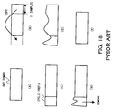
- the parallel-to-serial buffer 40 shown in FIG. 14 receives DMT symbols, each of which is represented by a simple rectangle in section (A) of FIG. 18.
- the buffer 40 modifies this DMT symbol, adding a copy of its last 16 samples to the beginning of the symbol, as shown in section (B) of FIG. 18.
- the added part is referred to as a "cyclic prefix," and the DMT symbol with such a cyclic prefix is sent to the D/A converter 50 so as to be converted to an analog signal at the sampling rate of 1.104 MHz, as shown in section (C) of FIG. 18.
- This analog signal is transmitted to the subscriber's premises over the metallic subscriber line 70.
- the signal reaching the subscriber's premises is distorted as a result of intersymbol interference as shown in section (D) of FIG. 18. This is because of a non-ideal frequency response of the metallic subscriber line 70 which exhibits uneven amplitude and delay (phase) characteristics.
- Such intersymbol interference is compressed within a 16-sample cyclic prefix through an equalization process provided by the TEQ unit 90 shown in FIG. 14, resulting in a waveform conceptually depicted in section (E) of FIG. 18. After that, the distorted cyclic prefix is removed at the serial-to-parallel buffer 100, thus yielding a clean DMT symbol with no effect of intersymbol interference.
- the TEQ unit 90 eliminates the effect of intersymbol interference from the received signal by manipulating cyclic prefixes. More specifically, the metallic subscriber line 70 has non-linear low-pass characteristics, which cause deterioration of transmission signals at higher frequency bands.
- the data signal being transmitted shows discontinuity between adjacent symbols. This discontinuity in the data signal causes an impulse response lasting for a certain time duration, when the signal passes through the above non-linear transmission channel. (Here, the term "impulse response" refers to the waveform that results at the output of the channel when its input is excited by an impulse.) Being superimposed on the main components of the data signal, the above impulse response will lead to signal deterioration.
- a cyclic prefix is attached to the beginning of each symbol by copying the last 16 samples of the symbol. This ensures continuity at a point where the prefix and symbol are joined, thus causing no unwanted impulse response in that part.
- the signal may still be discontinuous at the point where the beginning of the cyclic prefix is joined with the end of the previous symbol, which could cause an undesired impulse response.
- the interference at the latter part can be eliminated by (1) subjecting the received data signal to the TEQ unit 90 having a high-pass characteristic that works inversely with the low-pass characteristic of the metallic subscriber line 70, so that the impulse response will settle within the period of a cyclic prefix, and (2) removing the cyclic prefix, together with its distortion. In this way, the receiver unit decouples the received data signal from the effect of an unwanted impulse response, thus yielding its original waveform.
- the FEQ unit 120 works in the frequency domain. That is, the FEQ unit 120 performs equalization of the decoded output of the FFT unit 110 (FIG. 14) which contains multiple carriers having different frequencies. Separately for each individual carrier, the FEQ unit 120 compensates for amplitude and phase distortions of a transmission signal, which were incurred during the travel over the metallic subscriber line 70.
- the TEQ unit 90 is actually a finite impulse response (FIR) filter which operates as a channel equalizer in the time domain. As shown in section (E) of FIG. 18, the TEQ unit 90 should be designed so that intersymbol interference will completely settle within a cyclic prefix having a length of sixteen sample periods, and to this end, the TEQ unit 90 has to be tuned in an adaptive manner.
- FIR finite impulse response
- FIG. 19 an example of such adaptive algorithms for the TEQ unit 90 will be described below. While the system of FIG. 19 shares some elements with that of FIG. 14, the following explanation will focus on its distinctive points, affixing like reference numerals to like elements. Also, a series of elements from the IFFT unit 30 to the D/A converter 50 shown in FIG. 14 are now represented collectively as a single block 500 named "transmitter unit" in FIG. 19. Further, while FIG. 14 represents the TEQ training block 160 as a single functional unit, FIG. 19 shows it as a collection of more specific functional blocks. They include: a reference signal generator 610, a target channel 620, and an adder 630. It should also be noted that FIG. 19 omits the A/D converter 80 and serial-to-parallel buffer 100 for simplicity of explanation.
- the transmitter unit 500 is sending a signal X for use in a training process of the TEQ unit 90.
- the same signal X is produced locally by the reference signal generator 610, which is called the reference signal X.
- the target channel 620 serves as a target to be referenced when training the TEQ unit 90.
- the adder 630 calculates the difference E between the output Z of the FFT unit 110 and the output BX of the target channel 620, and supplies the result to the TEQ unit 90 and target channel 620.
- the above elements will operate as follows.
- the signal X transmitted by the transmitter unit 500 propagates through the metallic subscriber line 70, during which the amplitude and phase of its frequency components are varied.
- the TEQ unit 90 equalizes the received signal to compensate for the distortion introduced during its travel over the metallic subscriber line 70.
- the signal equalized as such in the time domain is then fed to the FFT unit 110 and converted into a frequency domain signal.
- the output of the FFT unit 110 is supplied to the adder 630.
- the reference signal generator 610 produces a reference signal X that corresponds to the transmission signal X.
- the target channel 620 multiplies each frequency component of the reference signal X by a predetermined coefficient.
- the adder 630 calculates the difference between the outputs of the FFT unit 110 and target channel 620, and feeds the result back to the TEQ unit 90 and target channel 620. Based on this difference signal, the TEQ unit 90 and target channel 620 adjust their coefficient values. More specifically, the adder 630 calculates the difference E between the output Z of the FFT unit 110 and the output BX of the target channel 620 when it is given a reference signal X, and then the TEQ unit 90 and target channel 620 are alternately adjusted in such a way that the following two conditions are both fulfilled. They are: (1) the length of the impulse response should be at most 16 sampling periods, and (2) the difference E (i.e., Z - BX) should be zero.
- the TEQ unit 90 obtains intended characteristics which confine the intersymbol interference within a 16-sample-long cyclic prefix of each received symbol, as shown in section (E) of FIG. 18. Note that the characteristic of the target channel 620 finally agrees with a combined characteristic of the metallic subscriber line 70 and TEQ unit 90.
- FIG. 19 has illustrated an implementation of the training algorithm in the frequency domain, it is also possible to realize the same in the time domain.
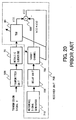
- FIG. 20 shows a system designed to train the TEQ unit 90 in the time domain by using a generally known training algorithm. Basically, those two training systems shown in FIGS. 19 and 20 operate in the same way, although they are designed to work in different domains. Unlike its counterpart shown in FIG. 19, however, the time-domain system of FIG. 20 employs a delay unit 720, while eliminating the FFT unit 110.
- the system of FIG. 20 further comprises a reference signal generator 710 and a target channel 730, both of which operate in the time domain.
- the reference signal generator 710 produces a time domain signal x(t) which is equivalent to what is converted from the transmission signal X.
- the delay unit 720 adds a predetermined amount of delay to the reference signal x(t) supplied from the reference signal generator 710.
- the target channel 730 is used as a target to be referenced when tuning the characteristic of the TEQ unit 90. It outputs a signal b(t)*x(t), where the function b(t) represents the characteristics of the target channel 730 itself, and the asterisk (*) denotes the convolution operator.
- the target channel 730 calculates a convolution integral of the delayed reference signal x(t) with the target transmission characteristics b(t).
- the adder 630 calculates the difference between the output z(t) of the TEQ unit 90 and the output b(t)*x(t) of the target channel 730. The result is fed back to the TEQ unit 90 and target channel 730. Based on this difference signal, the TEQ unit 90 and target channel 730 adjust themselves in such a way that the error output e(t) of the adder 630 will be zero.
- the above-described conventional system operates as follows.
- a signal X is transmitted at the sending end, its frequency components are varied during the transport over the metallic line 70.
- the TEQ unit 90 thus performs equalization of the received signal to compensate for the distortion.
- the resultant signal z(t) is then fed to the adder 630.
- the reference signal generator 710 produces a time-domain reference signal x(t), which is equivalent to the transmission signal X.
- the delay unit 720 delays this reference signal x(t) by a predetermined time interval, such that the output z(t) of the TEQ unit 90 will be in phase with that of the target channel 730.
- the target channel 730 convolves the reference signal x(t) with a combined characteristic b(t) of the metallic subscriber line 70 and TEQ unit 90 (excluding the delay time of the metallic subscriber line 70).
- the result of this convolution integral b(t)*x(t) is then supplied to the adder 630.
- the adder 630 calculates the difference e(t) between the output z(t) of the TEQ unit 90 and the output b(t)*x(t) of the target channel 730.
- the result is fed back to the TEQ unit 90 and target channel 730. Based on this result, the TEQ unit 90 and target channel 730 adjust themselves in an adaptive way.
- the TEQ unit 90 and target channel 730 perform training operations alternately so that the error output e(t) of the adder 630 will be zero.
- the TEQ unit 90 obtains intended characteristics, thus confining the intersymbol interference within a 16-sample-long cyclic prefix of each received symbol, as shown in section (E) of FIG. 18.
- FEQ unit is an equalizer operating in the frequency domain. Since the DMT modulation uses multitone carriers, it is actually configured as a collection of equalizers for individual carriers having different frequencies in such a way that uniform characteristics will be provided over various tones.
- FIG. 21 shows a combination of an FEQ unit 840 and a decoder 850, which correspond to the FEQ unit 120 and decoder 130 in FIG. 14, respectively.
- the FEQ unit 840 comprises a multiplier 810 which multiplies a given input signal Yi by a coefficient Wi. The values of the coefficients Wi are varied depending on the output of the adder 830.
- the decoder 850 comprises a decision unit 820 which outputs an estimated value Xi by guessing what the input signal Yi is likely to be.
- the adder 830 calculates the difference between the output Xi of the decision unit 820 and the output Zi of the multiplier 810, and based on the difference value, it determines the coefficients Wi for the multiplier 810.
- the above conventional equalizer operates as follows. Multiple carrier signals are modulated by the transmitter unit and transmitted over the metallic subscriber line 70. When they reach the receiving end, those carrier signals exhibit some distortion in their amplitude and phase values because of the non-ideal characteristics of the metallic subscriber line 70.
- the FEQ unit 120 compensates for such distortion of each individual carrier signal.
- the FEQ unit 120 provides as many equalization circuits of FIG. 21 as the number of carriers, and each such circuit employs its local decoder 130 to produce an estimated value and compensate for the deterioration in a particular carrier frequency band. That is, in order for the FEQ unit 120 to compensate for the amplitude and phase distortion, each individual equalization circuit (FIG. 21) has to work in an adequate manner in its own carrier frequency band.
- each FEQ unit 840 provides its output Zi to the corresponding decoder 850, thus yielding an estimated value Xi;
- the adder 830 calculates the difference Ei between the estimated value Xi and FEQ output Zi; and
- the coefficients Wi of the multiplier 810 are controlled so that the difference Ei will be zero.
- the decoder 850 further converts the estimated value Xi into data bits bi and supplies them to the parallel-to-serial buffer 140 (FIG. 14).
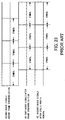
- FIG. 22 outlines an initialization sequence to start up an ADSL transmission unit.
- signals transmitted at this initialization stage 900 include continuous signals 910 and discontinuous signals 920. More specifically, in the first half of the initialization stage 900, the ADSL unit transmits continuous signals 910 such as repetitive synchronization symbols, and in the second half, it transmits discontinuous signals 920 such as wideband synchronization symbols.
- the transmitter unit When sending discontinuous signals, it is necessary for the transmitter unit to add a cyclic prefix to each DMT symbol to send, to enable the receiver unit to eliminate the effect of intersymbol interference from the received DMT symbols, as shown in section (C) of FIG. 18.
- the transmitter unit can use DMT symbols with no cyclic prefix as shown in section (A) of FIG. 18. That is, there is no need to add a cyclic prefix to DMT symbols in the latter case, because continuous signals do not suffer from intersymbol interference.
- the receiver unit has to synchronize itself to the timing of transmission frames to identify and extract each incoming symbol correctly from the received signal.
- the receiver unit can identify DMT symbols at any phase. In the case of discontinuous signals, however, correct DMT symbols can be identified only at one particular phase. Frame synchronization should therefore be established during an initialization stage where the transmission signal is continuous, so that the receiver unit will be able to correctly receive DMT symbols in a later communication session. More specifically, the receiver unit first captures the phase of DMT symbols at an initialization stage during which a continuousness transmission signal is provided, as shown section (A) of FIG. 23. It then attempts frame synchronization by shifting the captured phase as shown in section (B) of FIG. 23, so that DMT symbols can be extracted from discontinuous signals.
- the frame synchronization is performed after the TEQ training is completed, for the following reason.
- the TEQ unit adds some amount of delay, and this delay should also be considered as one of the parameters that affect the frame synchronization.
- both the aforementioned TEQ unit 90 and FEQ unit 120 are optimized in such environments where TCM crosstalk interference is prevalent, whether the system is in an initialization stage or in a normal communication session.
- One example of training algorithms for TEQ and FEQ units at an initialization stage in TCM crosstalk-prevalent environments is proposed in Japanese Patent Application No. 10-172464 (1998).
- the receiver unit when performing equalizer training, refers to inside symbols in FEXT bit map mode (single bit map mode), whereas it refers only to inside symbols, or successively refers to both inside and outside symbols in dual bit map mode.
- the coefficient updating step size for outside symbols should be set to the vicinity of zero (i.e., zero or a sufficiently small value).
- the time domain equalizer has to be adequately characterized through a training process, so that the intersymbol interference will be confined within a 16-sample-long cyclic prefix.
- the equalizer could lose its performance during a long time operation because of changes in temperature and consequent variations in the characteristics of a metallic subscriber line being used.
- it is necessary to continue some processing to adapt the equalizer even after the initialization sequence is finished.
- no practical methods have been proposed so far to meet this requirement.
- Another problem is that the training process in the initialization sequence consumes a large amount of processing resources and time, while the equalizer training is an essential process to obtain a good TEQ characteristic.
- Still another problem with the conventional systems is the lack of training algorithms in an environment where TCM crosstalk interference is prevalent. Although some algorithms for use in the initialization phase are available, as described earlier in item (10), no practical algorithms or implementation methods have been proposed for how to train the equalizer during normal data communication sessions.
- an object of the present invention is to provide a data transmission system which reliably trains its equalizers both in an initialization phase and in a normal communication session.
- the transmitter unit comprises the following elements: a modulator which applies a prescribed modulation on a data signal to be transmitted; a prefixing unit which adds a cyclic prefix to the data signal modulated by the modulator; a transmitter which sends the data signal with the cyclic prefix over the subscriber line.
- the receiver unit comprises the following element: a receiver which receives the data signal sent from the transmitter; a processor which processes the data signal received by the receiver so that impairment introduced in the received data signal will be confined within the cyclic prefix, where the impairment has been introduced during the transport of the data signal over the subscriber line; a target channel which provides reference characteristics for use in training the processor; a first training unit which performs training at an initialization stage by tuning both of the target channel and the processor; and a second training unit which performs training by tuning the processor when a normal communication session takes place.
- Another object of the present invention is to provide a receiver unit which maintains the performance of equalizers with reduced processing time and loads.
- a receiver unit which receives data sent from a transmitter unit over a subscriber line.
- This receiver unit comprises the following elements: a receiver which receives a data signal sent from the transmitter unit; a processor which processes the data signal received by the receiver so that impairment introduced in the received data signal will be confined within a cyclic prefix, where the impairment has been introduced during the transport of the data signal over the subscriber line; a target channel which provides reference characteristics for use in training the processor; a first training unit which performs training at an initialization stage by tuning both of the target channel and the processor; and a second training unit which performs training by tuning the processor when a normal communication session takes place.
- FIG. 1 is a conceptual view of the present invention, where a transmitter unit 1 sends data to a receiver unit 3 over a metallic subscriber line 2.
- the metallic subscriber line 2 is an existing telephone line laid for public telecommunication services, etc., which serves as a medium for transporting a data signal from the transmitter unit 1 to the receiver unit 3.
- the receiver unit 3 receives the data signal transmitted over the metallic subscriber line 2, and restores the data signal to its original form.
- the transmitter unit 1 comprises a modulator 1a, a prefixing unit 1b, and a transmitter 1c.
- the modulator 1a applies a prescribed modulation process (e.g., DMT) to a data signal to be transmitted.
- the transmitter 1c sends out the data signal with such cyclic prefixes to the metallic subscriber line 2.
- the receiver unit 3 comprises a receiver 3a, a processor 3b, a target channel 3c, a first training unit 3d, and a second training unit 3e.
- the receiver 3a receives a data signal that is sent by the transmitter 1c in the transmitter unit 1. While the received data signal is distorted during the transport over the metallic subscriber line 2, the processor 3b processes the signal so that the distortion of each symbol will be confined within the period of its cyclic prefix.
- the target channel 3c has such a characteristic that is regarded as a reference when training the processor 3b. According to this reference characteristic, the target channel 3c processes a given reference signal, and supplies the result to the first training unit 3d and second training unit 3e.
- the reference signal is provided by a reference signal generator which is not shown in FIG. 1.
- the first training unit 3d performs a training process by tuning both the target channel 3c and the processor 3b when the receiver unit 3 begins communication (i.e., at the initialization stage).
- the second training unit 3e performs a like training process by tuning mainly the processor 3b in a normal communication session.
- the transmitter unit 1 has called up the receiver unit 3 and a circuit has been established between those two parties.
- the transmitter unit 1 and receiver unit 3 first invoke an initialization process, negotiating the details of communication schemes and various parameters.
- the processor 3b performs an equalizer training process as follows.
- the receiver 3a receives a reference signal (e.g., synchronization symbols) from the transmitter unit 1, and the processor 3b applies a predefined process to this reference signal. Because the initialization has not been completed at this stage, the processor 3b applies what is defined as a default process.
- the reference signal is received and processed in this way and passed to the first training unit 3d.
- the target channel 3c receives a like reference signal from a reference signal generator (not shown).
- the target channel 3c processes this reference signal with its prescribed characteristics, which serve as a reference model in the training processes. Because the initialization is not completed at this stage, the target channel 3c provides its default characteristics.
- the first training unit 3d calculates the difference between the outputs of the target channel 3c and processor 3b. It alternately trains the processor 3b and target channel 3c in such a way that the difference will become zero, and that the duration of impulse response of the target channel 3c will be within 16 sample periods. This adjustment provides the processor 3b with a desirable characteristic adapted to the metallic subscriber line 2, so that the disturbance caused by the metallic subscriber line 2 will be confined within a cyclic prefix. As a result of the above, the target channel 3c obtains characteristics that are equal to the combined characteristics of the metallic subscriber line 2 and processor 3b.
- the training of the processor 3b is followed by a frame synchronization process, and after that, the transmitter unit 1 and receiver unit 3 start to communicate in a normal mode of operation. Even in this normal communication session, however, the metallic subscriber line 2 may exhibit some variations in its characteristics as time goes by. If this happens, the processor 3b can no longer maintain its advantage of optimized compensation, thus causing degradation in the quality of communication.
- the data transmission system is configured to fix the characteristic of the target channel 3c after the frame synchronization is finished, thus maintaining its state established by the training process at the initialization stage.
- the system is also configured to follow the variations in a normal communication mode by activating the second training unit 3e to adjust the processor 3b in an appropriate manner.
- the second training unit 3e extracts a reference signal (e.g., synchronization symbol), which has been received by the receiver 3a and processed by the processor 3b in a prescribed manner.
- the target channel 3c is receiving at this moment a like reference signal from a reference signal generator (not shown). With the given characteristic, the target channel 3c processes this reference signal and supplies the result to the second training unit 3e.
- the second training unit 3e now calculates the difference between the outputs of the target channel 3c and processor 3b, and adjusts the processor 3b in such a way that the difference will stay zero.
- the target channel 3c is implemented as a finite impulse response (FIR) filter. Even if the amount of reception delay is varied as a result of frame synchronization, those FIR filters can easily adapt themselves to such variations by changing their coefficients' order according to the increased or decreased delay.
- FIR finite impulse response
- the data transmission system is configured to keep adaptive to variations in normal communication sessions by activating the second training unit 3e to solely adjust the processor 3b, while fixing the characteristics of the target channel 3c which has been established at the initialization stage.
- This configuration permits the system to maintain the quality of data communication.
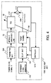
- FIG. 2 is a block diagram which shows a typical configuration of data transmission system of the present invention. Since the structure shown in this FIG 2. is similar to the conventional system described earlier in FIG. 19, the following explanation will focus on its distinctive elements, while affixing like reference numerals to like elements. Compared with the conventional system of FIG. 19, the proposed system newly employs a controller 1210, while other elements can also be seen in FIG. 19. As will be described later, this controller 1210 controls a target channel 620 and other elements, referring to the output of an adder 630.
- the operation of the present embodiment will now be described below.
- the transmitter unit 500 called up the receiver unit 1200 and a circuit has been established between those two parties.
- the receiver unit 1200 then begins an initialization process.
- the controller 1210 supplies the target channel 620 with the output signal of the adder 630, causing the target channel 620 to adapt to the characteristics of the metallic subscriber line 70.
- the details of this equalizer training will not be described here again, since it is similar to what has been explained in FIG. 19.
- Section (A) of FIG. 3 illustrates the output signal 1110 of the TEQ unit 90 after training, together with an impulse response 1120 of the target channel 620.
- the training of the TEQ unit 90 is followed by a frame synchronization process.
- Shown on the left-hand side of section (B) of FIG. 3 is the output signal 1130 of the TEQ unit 90 after frame synchronization.
- the two waveforms indicate that the frame synchronization has caused a phase shift on the output signal of the TEQ unit 90. That is, the current TEQ output signal 1130 has a different phase, compared with its previous state 1110, although the reference signal (i.e., transmission signal X in this case) has not changed.
- the target channel 620 does not allow for that phase shift because the training process was done before frame synchronization.
- the controller 1210 manipulates the phase characteristic of the target channel 620 so that it will exhibit a time-shifted impulse response 1140 as shown in section (B) of FIG. 3.
- the receiver unit 1200 now migrates to the normal communication mode. It continues to adjust the TEQ unit 90 to keep adaptive to the subscriber line conditions, while holding the current characteristic of the target channel 620.
- the characteristics of the target channel 620 may not be completely locked, but allowed to vary within a certain limited range (e.g., such a range where the number of data bits assigned to each carrier is not affected), in addition to keeping the TEQ unit 90 adaptive to the line conditions.
- the controller 1210 manipulates the characteristics of the target channel 620 when the frame synchronization is established, so that it will exhibit a time-shifted response. It is therefore possible to maintain the quality of communication even if the frame synchronization results in a substantial phase shift.
- the first embodiment is also advantageous in its simplicity of training control during normal communication sessions. Once the communication is started, the characteristics of the target channel 620 is locked, and only the TEQ unit 90 is subjected to the continued training process. Accordingly, the quality of communication services can be maintained with a minimum processing effort.
- FIG. 4 illustrates a data transmission system which performs training processes in the time domain.
- the second embodiment differs from the first embodiment of FIG. 2 in the following points.
- the FFT unit 110 is not present in the training loop.
- a reference signal generator 710 produces a time-domain reference signal x(t) and a target channel 730 is configured to operate with a time domain signal.
- a delay unit 720 is placed between the reference signal generator 710 and target channel 730. Further, the controller 1210 controls the delay unit 720 in addition to the target channel 730.
- the other elements are common to the first embodiment shown in FIG. 2.
- the reference signal generator 710 produces a time-domain local reference signal x(t), which is a time-domain representation of the transmission signal X.
- the delay unit 720 delays the local reference signal x(t) by a predetermined time period.
- the target channel 730 convolves this delayed reference signal x(t) with the target transmission characteristics b(t).
- the second embodiment of the present invention operates as follows.
- the receiver unit 1300 accepts an incoming transmission signal X, which is a reference signal produced and transmitted by the sending end. This signal is distorted during the transport over the non-ideal metallic subscriber line 70.
- the TEQ unit 90 in the receiver unit 1300 convolves this transmission signal X with a predetermined series of coefficients, thus outputting a time domain signal z(t).
- the reference signal generator 710 on the other hand, locally produces a reference signal x(t) in the time domain, which corresponds to the transmission signal X.
- the delay unit 720 delays this reference signal x(t) by a predetermined time period.
- the target channel 730 receives the delayed reference signal x(t), the target channel 730 convolves it with a series of coefficients b(t) representing the target characteristics.
- the target channel 730 is actually a band-pass filter implemented by using FIR filter techniques. More specifically, this band-pass filter is constructed as a combination of a low-pass filter representing the metallic subscriber line 70 and a high-pass filter representing the TEQ unit 90.
- the adder 630 calculates the difference between the output of the TEQ unit 90 and that of the target channel 730, and supplies the result to the TEQ unit 90 and controller 1210. According to this difference signal, the TEQ unit 90 and target channel 730 are tuned alternately. That is, the characteristics of the TEQ unit 90 and target channel 730 are adjusted so that the output of the adder 630 will become zero. The adjustment stops when the output of the adder 630 falls below a predetermined threshold.
- the controller 1210 holds the current setup of the delay unit 720 and target channel 730, while the training of the TEQ unit 90 remains active. That is, when the transmitter unit 500 sends a reference transmission signal X during the normal communication mode, the TEQ unit 90 is tuned so that the output of the adder 630 will be zero. In this way, the receiver unit 1300 is free from the intersymbol interference, even if the metallic subscriber line 70 changes in its transmission characteristics.
- the second embodiment of the present invention operates in the time domain, providing the same capabilities as in the first embodiment of FIG. 2.
- the characteristics of the target channel 730 may not be completely locked, but allowed to vary within a range where the number of data bits assigned to each carrier is not affected, in addition to keeping the TEQ unit 90 adaptive to the subscriber line conditions.
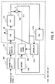
- FIG. 5 shows a specific embodiment which is designed to perform equalizer training with any kind of transmission signal.
- This third embodiment has some elements that have already been explained in FIG. 2. Thus the following explanation will focus on its distinctive points, while affixing like reference numerals to like elements.
- the third embodiment differs from the first embodiment of FIG. 2 in that the reference signal generator 610 is not present, and that an FEQ unit 1410 and a decoder 1420 are involved.
- the other elements are common to the first embodiment shown in FIG. 2.
- the FEQ unit 1410 performs equalization on the output signals of the FFT unit 110 so that every frequency component will have a unified characteristic.
- the decoder 1420 provides a best estimate X for the output signal of the FEQ unit 1410, thus reproducing its original signal.
- the third embodiment of the present invention operates as follows. First, when the receiver unit 1400 is at an initialization stage, the TEQ unit 90 applies a prescribed process to the transmission signal X sent from the transmitter unit 500.
- the FFT unit 110 then converts the output signal of the TEQ unit 90 into a signal in the frequency domain.
- the FEQ unit 1410 performs equalization on the output signals of the FFT unit 110 so that every frequency component will have a unified characteristic.
- the decoder 1420 outputs estimated values X to reproduce the original data signals. The resultant signals are supplied to the target channel 620.
- this output signal of the decoder 1420 is identical with the transmission data signal X, or equivalently, the receiver unit 1400 is producing a reference signal X locally. While the receiver unit 1200 of FIG. 2 operates exclusively with a predetermined reference signal X, the receiver unit 1400 of FIG. 5 can use any kind of transmission signal as the reference signal.
- the target channel 620 applies a predetermined process to the output from decoder 1420; that is, it multiplies individual frequency components by a predetermined series of coefficients.
- the adder 630 calculates the difference between the output of FFT unit 110 and that of target channel 620, and supplies the result to the TEQ unit 90 and target channel 620 (via the controller 1210). The characteristics of the TEQ unit 90 and target channel 620 are alternately tuned so that the output of the adder 630 will become zero.
- the training process is followed by a frame synchronization process.
- the frame synchronization brings about a certain amount of phase shift in the received signal. Therefore, when the frame synchronization is established, the controller 1210 makes an adjustment to the target channel 620 in order to cancel the phase shift. This adjustment is performed in such a manner that the output of the adder 630 will be zero.
- the present characteristics of the target channel 620 is locked, and only the TEQ unit 90 is subjected to the continued training process. In this way, the receiver unit 1400 is free from the intersymbol interference, even if the metallic subscriber line 70 shows some variations in its transmission characteristics.
- the receiver unit 1400 employs an FEQ unit 1410 and a decoder 1420 so as to produce a reference signal from the transmission signal X and supply the target channel 620 with the produced signal.
- This configuration permits the receiver unit 1400 to performs a training process with any kind of transmission signal. That is, it is possible to use data symbols transmitted during a normal communication session to tune the TEQ unit 90 in the frequency domain.
- this fourth embodiment can use any kind of incoming signal for equalizer training purposes.
- the fourth embodiment realizes this function in the time domain.
- the fourth embodiment of FIG. 6 is different from the third embodiment of FIG. 5 in the following points.
- the adder 630 is interposed between the TEQ unit 90 and FFT unit 110.
- an IFFT unit 1510 and a delay unit 750 are newly added.
- the IFFT unit 1510 receives frequency domain signals from the decoder 1420 and converts them into a time domain signal.
- the delay unit 750 adds a predetermined amount of delay to the time domain signal x(t) supplied from the IFFT unit 1510.
- the target channel 760 convolves the delayed time-domain signal x(t) with the target transmission characteristics b(t).
- the fourth embodiment of the present invention operates as follows. First, at the initialization stage, the transmission signal X sent from the transmitter unit 500 Is subjected to the TEQ unit 90 for equalization in the time domain. The resultant signal z(t) is then supplied to the FFT unit 110 and adder 630. The FFT unit 110 converts the time domain signal z(t) into a frequency domain signal Z. The FEQ unit 1410 performs equalization on the signal Z in the frequency domain. The decoder 1420 outputs an estimated value X for the output signal of the FEQ unit 1410, thus reproducing its original information. The IFFT unit 1510 converts the reproduced data signal X back into a time domain signal x(t).
- This time-domain output signal x(t) of the IFFT unit 1510 is then given a predetermined time delay by the delay unit 750.
- the target channel 760 convolves the output signal of the delay unit 750 with the target transmission characteristics b(t).
- the adder 630 calculates the difference between the outputs of TEQ unit 90 and target channel 760 and supplies the result to the controller 1210 and TEQ unit 90.
- the above training process is executed at the initialization stage, in which the target channel 760 and TEQ unit 90 are alternately adjusted.
- a frame synchronization process is initiated.
- the controller 1210 makes an adjustment to the delay unit 750, such that the output of the adder 630 will be zero. In this way, the receiver unit 1500 cancels the phase shift that was introduced by the frame synchronization process.
- the controller 1210 holds the current setup of the delay unit 750 and target channel 760, while the training of the TEQ unit 90 continues.
- the transmission signal X includes data symbols and synchronization symbols, both of which can be used to train the TEQ unit 90.
- the fourth embodiment permits the receiver unit 1500 to performs training of the TEQ unit 90 with any kind of transmission signal.
- FIG. 7 shows a specific embodiment which is designed to train the equalizer with reduced processing time and load.
- This fifth embodiment has some elements that have already been explained in FIG. 2. Thus the following explanation will focus on its distinctive points, while affixing like reference numerals to like elements.
- the fifth embodiment differs from the first embodiment of FIG. 2 in that the proposed receiver unit 1600 employs a reception signal level discriminator 1610, a TEQ coefficient table 1620, and a divider 1630.
- FIG. 7 shows only a relevant part of the receiver unit 1600. Other functional blocks of the receiver unit 1600 are omitted for simplicity.
- the reception signal level discriminator 1610 examines an incoming signal received through the metallic subscriber line 70 and notifies the TEQ coefficient table 1620 of its magnitude.
- the TEQ coefficient table 1620 stores various reception signal levels and their associated TEQ coefficients. When a specific signal level is reported by the reception signal level discriminator 1610, the TEQ coefficient table 1620 provides relevant TEQ coefficients.
- the received signal is processed accordingly by the TEQ unit 90 and FFT unit 110.
- the divider 1630 divides the resultant output signal Z by a reference signal X that is locally produced by a reference signal generator 610, and supplies the result to the target channel 620.
- the target channel 620 configures itself with the output of the divider 1630.
- the fifth embodiment of the present invention operates as follows. Suppose that the transmitter unit 500 begins communication with the receiver unit 1600 and they now invoke an initialization process.
- the reception signal level discriminator 1610 determines the magnitude of the received signal and notifies the TEQ coefficient table 1620 of the result.
- the TEQ coefficient table 1620 provides the TEQ unit 90 with a set of TEQ coefficients corresponding to the notified reception signal level.
- the above mechanism is based on such a concept that the conditions of the metallic subscriber line 70 can be identified to a certain extent by examining the reception signal level.
- the actual relationships between various reception signal levels and suitable TEQ coefficients are previously measured, and a TEQ coefficient table 1620 is formulated according to that experimental results.
- the TEQ unit 90 is configured with a particular set of TEQ coefficients that is supposed to be most suitable for the current signal level.
- the transmitter unit 500 begins to transmit a reference signal X
- the TEQ unit 90 receives and convolves it with the TEQ coefficients given above.
- the FFT unit 110 converts the output of the TEQ unit 90 into a frequency domain signal.
- the divider 1630 then divides these output signal Z of the FFT unit 110 by a reference signal X locally produced by the reference signal generator 610. The result of this division is supplied to the target channel 620.
- the target channel 620 configures itself with the output values of the divider 1630. In this way, the TEQ unit 90 and target channel 620 are adapted to the actual transmission characteristics of the metallic subscriber line 70.
- the receiver unit 1600 cancels the resultant phase shift by readjusting the target channel 620, as described in the first embodiment of FIG. 2.
- the system then enters a normal communication mode, where the receiver unit 1600 holds the current setup of the target channel 620, while continuing training operations to the TEQ unit 90 in the way as in the first embodiment of FIG. 2.
- the fifth embodiment is distinct from others in that it utilizes the relationships between various reception signal levels and suitable parameters of the TEQ unit 90 which are obtained through actual measurement. Those records are stored in a table, and the TEQ unit 90 is trained on the basis of this table. Further, in the fifth embodiment, the receiver unit 1600 determines parameters of its target channel 620 from the local reference signal and the output of the FFT unit 110. This training process can be executed in a very short time. While the fifth embodiment has been described as using reception signal levels as the determinant of TEQ coefficients, the system may also be configured to determine the coefficients of the TEQ unit 90 on the basis of waveforms or frequency characteristics of incoming signals.
- FIG. 8 illustrates a specific embodiment which uses FEXT and NEXT periods effectively to accelerate training processes.
- This sixth embodiment has some elements that have already been explained in the conventional system of FIG. 19. The following explanation will focus on its distinctive points, while affixing like reference numerals to like elements.
- the sixth embodiment differs from the conventional system of FIG. 19 in that it advantageously employs a reception signal averaging unit 1710.
- the functional blocks constituting this system utilizes far-end crosstalk (FEXT) periods and near-end crosstalk (NEXT) periods in a distinctive way as indicated by the broken line in FIG. 8. More specifically, the system shown in FIG. 8 is divided into two parts by the broken line; the functional blocks in the upper part operate in FEXT periods, while those in the lower part operate in NEXT periods.
- the reception signal averaging unit 1710 extracts reference signals X, which are contained in the received signal, for the duration of several symbol intervals. It calculates the average of them and supplies it to the TEQ unit 90. Other symbols contained in the received signal are delivered intact to the TEQ unit 90.
- the sixth embodiment of the present invention operates as follows.
- the reception signal averaging unit 1710 receives reference signals X for several symbol intervals during a FEXT period and calculates the average of them. The average value is then supplied to the TEQ unit 90 for use in a training operation in the subsequent NEXT period.
- the TEQ unit 90 and target channel 620 are alternately adjusted so that the adder 630 will output zero. The details of this process will not be described here again, since it is similar to what has been explained in FIG. 19.
- the training of the TEQ unit 90 can be executed during a NEXT period when the system is relatively lightly loaded.
- the sixth embodiment takes advantage of the difference between the NEXT and FEXT periods, thus enabling optimal use of system resources. While the sixth embodiment has been described as operating in the frequency domain, it can also be realized in a system that operates in the time domain.
- FIG. 9 shows the concept of the seventh embodiment which performs frame synchronization with a target channel 1840, which is identical with what was explained as the target channel 620 in FIG. 2.
- a maximum value detector 1850 is employed to detect the maximum value of the target channel output within a time range whose length is the same as that of a cyclic prefix.
- a frame boundary calculation unit 1860 detects a particular signal phase which the maximum value detector 1850 indicates as the maximum point. The frame boundary calculation unit 1860 supplies this phase value to a frame synchronization unit (not shown) as a boundary of frames.
- the seventh embodiment of the present invention operates as follows.
- the target channel 620 after being sufficiently trained, shows the same characteristics as the combined characteristic of the metallic subscriber line 70 and TEQ unit 90. This fact suggests that the phase lag of a transmission signal that has been received through the metallic subscriber line 70 and processed by the TEQ unit 90 is equal to that of the target channel 620. Since a frame boundary has to lie on the phase point that is identified by subtracting the TEQ delay from the above phase lag, it is possible to achieve a frame synchronization by: (1) examining the output of the target channel 620 within a specific time range which is as long as a cyclic prefix, (2) finding an exact point at which the target channel 620 shows its peak output, and (3) identifying a frame boundary using the phase of that peak point.
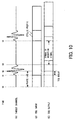
- FIG. 10 is a timing diagram which gives more details about how the frame synchronization is performed with the target channel 620.
- the phase lag of the target channel 620 is measured as an interval between two time points t0 and t2, where t0 is the time reference and t2 is the time when the target channel 620 shows a peak output in its impulse response.
- the time range between t1 and t3 corresponds to the cyclic prefix of a DMT symbol in question, within which the maximum output of the target channel 620 can be found.
- this time range is where the output of the TEQ unit 90 would show the most dominant effect of intersymbol interference due to the transmission characteristics of the metallic subscriber line 70.
- the remaining period from t3 to time t4 is regarded as a time range where no intersymbol interference is observed. For this reason, the range between t3 and t4 can be validated as a received DMT symbol.
- the maximum value detector 1850 finds a maximum power level that the response of the target channel 620 exhibits within a time range being as long as a cyclic prefix.
- the frame boundary calculation unit 1860 detects a particular phase at which the maximum value detector 1850 finds a maximum value, and calculates the frame boundary from the detected peak phase lag.
- the resultant data is supplied to a frame synchronization circuit (not shown).
- the frame boundary lies at time point t1, which is calculated by subtracting the TEQ delay time from the above peak phase lag.
- the present invention establishes frame synchronization in this way, taking advantage of the nature of the target channel 620.
- the training of the TEQ unit 90 is performed in the time domain, as in the second embodiment of FIG. 4, the obtained delay parameter is set to the delay unit 720 to cause the frame synchronization to take effect.
- FIG. 11 is a block diagram of an embodiment which automatically sets up a delay unit by calculating the delay time in the course of a training operation for the TEQ unit 90.
- this eighth embodiment provides a specific method to determine a delay time parameter for the delay unit 720 described earlier in the second embodiment of FIG. 4.
- the time domain training algorithm is used to tune the TEQ unit 90. According to this algorithm, a local reference signal x(t) produced by the reference signal generation block 710 is fed to the target channel 730 via the delay unit 720.
- the delay time parameter of this delay unit 720 has to be determined so that the output b(t)*x(t) of the target channel 730 will be in phase with the output z(t) of the TEQ unit 90.
- the eighth embodiment gives an effective solution to this problem by using the correlation between input signals being supplied to the TEQ unit 90 and target channel 730.
- the receiver unit 1800 thus employs a correlator 1810 which calculates the correlation coefficient between an incoming signal entering the TEQ unit 90 and the output signal of the delay unit 720. According to the result of this calculation, the parameter of the delay unit 720 is determined.
- the eighth embodiment of the present invention operates as follows.
- a reference signal X is received from the transmitter unit 500
- the receiver unit 1800 supplies this signal to its TEQ unit 90 and correlator 1810.
- the reference signal generator 710 locally produces a like reference signal, and supplies it to the delay unit 720.
- the delay unit 720 is configured to have a certain default delay time, which may be zero or any other value.
- the receiver unit 1800 then calculates the correlation between the received reference signal and the locally generated reference signal that has passed through the delay unit 720.
- FIG. 12 is a flowchart which shows a process executed by a correlator 1810, which comprises the following steps.
- the correlation calculation unit 1810 captures the output signal of the delay unit 720 and calculates the correlation with the averaged incoming signal, starting with a certain initial delay time and increasing (or decreasing) the delay time by a predetermined step size, until the repetition reaches N times. During this processing, the correlation calculation unit 1810 finds a particular delay time at which the two signals show the best correlation, and the delay unit 720 can be optimized with this delay time parameter.
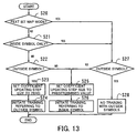
- FIG. 13 is a flowchart which explains an example of such a training process which allows for NEXT noise interference. This process comprises the following steps.
- the training is performed only with inside symbols, and not with outside symbols, as in the case of FEXT bit map mode.
- the training is performed with inside symbols, as in the option (2-1), and also with outside symbols, setting the coefficient updating step size of the TEQ unit 90 to a very small value or zero. As a result, the training process can be accomplished with a minimized NEXT noise interference.
- the present invention ensures data communication with optimized system parameters, which cope with variations in the transmission characteristics of a metallic subscriber line, due to the changes in temperature or the like.
- the equalizer training can be accomplished with reduced processing load and time. This contributes to quick start up of the system.
- the present invention enables a stable communication session In a TCM crosstalk-prevalent environment.
- the present invention provides a data transmission system which uses a subscriber line to transport data from a transmitter unit to a receiver unit.
- the transmitter unit comprises: a modulator which applies a prescribed modulation on a data signal to be transmitted; a prefixing unit which adds a cyclic prefix to the data signal modulated by the modulator; a transmitter which sends the data signal with the cyclic prefix over the subscriber line.
- the receiver unit comprises: a receiver which receives the data signal sent from the transmitter; a processor which processes the data signal received by the receiver so that impairment introduced in the received data signal will be confined within the cyclic prefix, where the impairment has been introduced during the transport of the data signal over the subscriber line; a target channel which provides reference characteristics for use in training the processor; a first training unit which performs training at an initialization stage by tuning both of the target channel and the processor; and a second training unit which performs training by tuning the processor when a normal communication session takes place.
- This structure of the system enables quick training of the processor not only in an initialization, but also in a normal communication session.
- the present invention provides a receiver unit which receives data sent from a transmitter unit over a subscriber line.
- This receiver unit comprises: a receiver which receives a data signal sent from the transmitter unit; a processor which processes the data signal received by the receiver so that impairment introduced in the received data signal will be confined within a cyclic prefix, where the impairment has been introduced during the transport of the data signal over the subscriber line; a target channel which provides reference characteristics for use in training the processor; a first training unit which performs training at an initialization stage by tuning both of the target channel and the processor; and a second training unit which performs training by tuning the processor when a normal communication session takes place.
- This structure enables the receiver unit to reliably receive data signals sent from the transmitter unit in a normal communication session.
- the present invention provides a data transmission system which uses a subscriber line to transport data from a transmitter unit to a receiver unit.
- the transmitter unit comprises: a modulator which applies a prescribed modulation on a data signal to be transmitted; a prefixing unit which adds a cyclic prefix to the data signal modulated by the modulator; a transmitter which sends the data signal with the cyclic prefix over the subscriber line.
- the receiver unit comprises the following element: a receiver which receives the data signal sent from the transmitter; a processor which processes the data signal received by the receiver so that impairment introduced in the received data signal will be confined within the cyclic prefix, where the impairment has been introduced during the transport of the data signal over the subscriber line; a target channel which provides reference characteristics for use in training the processor; a storage unit which stores a plurality of parameter sets either of which is to be set to the processor; a selection unit which selects one of the plurality of parameter sets, according to a signal reception condition that is observed by the reception unit; and a setting-up unit which sets up the processor with the parameter set selected by the selection unit.
- This structure of the system enables quick training of the processor.
- the present invention provides a receiver unit which receives data sent from a transmitter unit over a subscriber line.
- This receiver unit comprises: a receiver which receives a data signal sent from the transmitter unit; a processor which processes the data signal received by the receiver so that impairment introduced in the received data signal will be confined within a cyclic prefix, where the impairment has been introduced during the transport of the data signal over the subscriber line; a storage unit which stores a plurality of parameter sets either of which is to be set to the processor; a selection unit which selects one of the plurality of parameter sets, according to a signal reception condition that is observed by the reception unit; and a setting-up unit which sets up the processor with the parameter set selected by the selection unit.
- This structure realizes an equalizer training process with reduced processing loads.
Abstract
Description
- The present invention relates to a data transmission system and a receiver unit therefor. More particularly, the present invention relates to a data transmission system which transports data between a transmitter unit and a receiver unit over a telephone subscriber loop, as well as to the receiver unit used in this system.
- In recent years, the use of multimedia communication services such as the Internet has become increasingly ubiquitous in our daily activities, both at work and at home. To meet such user requirements, there is an urgent need to provide highly reliable, cost effective digital access network systems. However, constructing a completely new telecommunication infrastructure for multimedia services is extremely costly and time consuming. This has motivated various proposals of new high-speed data communication techniques that use existing telecommunication networks. Digital Subscriber Lines (xDSL), for example, are known as one of the enabling technologies for high-speed data communications over plain old phone lines. This xDSL technology is a collection of signal transmission techniques using subscriber lines, and in another aspect, it is an advanced modulation/demodulation technique. Such xDSL techniques are broadly divided into two groups: ones that provide symmetric upstream and downstream transmission rates, and ones that provide asymmetric rates. Here, the term "upstream" refers to the direction from a subscriber's premises to its nearest central office, and the "downstream" refers to the opposite direction. The ITU-T recommendations for Asymmetric DSL (ADSL) include the following two versions: G.992.1 (G.dmt) for a downstream transmission rate of about 6 Mbps, and G.992.2 (G.lite) for about 1.5 Mbps. Both versions use Discrete Multitone (DMT) techniques for signal modulation.
- Conventional DMT modulation techniques will be described below with reference to FIG. 14, focusing on the downstream signal modulation and demodulation in a G.lite-based ADSL system. The upper half of FIG. 14 shows a transmitter unit which comprises: a serial-to-
parallel buffer 10, anencoder 20, anIFFT unit 30, a parallel-to-serial buffer 40, a D/A converter 50, and atransmission bit map 60. The serial-to-parallel buffer 10 stores transmission data for a single symbol period of 250 microseconds (i.e., the reciprocal of asymbol rate 4 kHz) and converts it into a parallel data format. Theencoder 20 applies a prescribed modulation processing to the parallel data supplied from thebuffer 10. The inverse fast Fourier transform (IFFT)unit 30 processes the output data of theencoder 20 using IFFT algorithms. The parallel-to-serial buffer 40 converts the transformed data back into a serial data format, as well as adding a cyclic prefix (described later) to each symbol. The digital-to-analog (D/A)converter 50 converts the serial data to an analog signal at a sampling rate of 1.104 MHz and outputs it to ametallic subscriber line 70. Thetransmission bit map 60 is an allocation table describing how many data bits should be assigned to each DMT carrier. This table is called the "bit map" in the ADSL terminology. - The lower half of FIG. 14 shows a receiver unit, which comprises: an A/
D converter 80, aTEQ unit 90, abuffer 100, anFFT unit 110, anFEQ unit 120, adecoder 130, a parallel-to-serial buffer 140, a reception bit map 150, and aTEQ training block 160. The analog-to-digital (A/D)converter 80 receives a DMT-modulated analog signal transmitted over themetallic subscriber line 70 and converts it into digital form at a sampling rate of 1.104 MHz. The time domain equalizer (TEQ)unit 90 then processes this digital data signal in a prescribed manner, so that intersymbol interference (ISI) to a cyclic prefix, which has been added at the parallel-to-serial buffer 40, will settle within the period of that cyclic prefix. The serial-to-parallel buffer 100 converts the output data of theTEQ unit 90 into parallel data, after removing a cyclic prefix from each symbol. The fast Fourier transform (FFT)unit 110 converts the output data of the serial-to-parallel buffer 100 into parallel data signals in the frequency domain by using FFT algorithms. The frequency domain equalizer (FEQ)unit 120 equalizes those frequency-domain data signals according to the transmission characteristics (or frequency response) of themetallic subscriber line 70. Thedecoder 130 demodulates the output data of theFEQ unit 120 in a prescribed manner. The parallel-to-serial buffer 140 receives parallel data from thedecoder 130 and converts it into serial data. As the counterpart of thetransmission bit map 60, the reception bit map 150 stores information about the number of data bits assigned to each carrier at the sending end. Based on this information, adecoder 130 and parallel-to-serial buffer 140 decodes the received data. TheTEQ training block 160 adjusts the characteristics of theTEQ unit 90, with reference to the output signals of theFFT unit 110. - The above-described conventional system operates as follows. The transmitter unit accepts data to be transmitted at the serial-to-
parallel buffer 10, which actually stores data bits for a single symbol period of 250 microseconds (i.e., the reciprocal of thesymbol rate 4 kHz). Those stored data bits are divided into groups according to the bit allocation previously defined in thetransmission bit map 60. They are then supplied to theencoder 20, which maps each given bit sequence to specific code points in the signal constellation of quadrature amplitude modulation. Those constellation points are passed to the IFFTunit 30. The IFFTunit 30 performs inverse fast Fourier transform to accomplish the quadrature amplitude modulation of each constellation point. The data signal modulated in this way is then output to the parallel-to-serial buffer 40. Note here that the DMT modulation is realized by a combination of theencoder 20 andIFFT unit 30. - The parallel-to-
serial buffer 40 now chooses the 240th to 255th samples of the IFFT output data and adds a copy of those sixteen samples to the beginning of a DMT symbol. This is called the "cyclic prefix," the details of which will appear in a later section. The symbol data with a cyclic prefix is now sent from the parallel-to-serial buffer 40 to the D/A converter 50. The D/A converter 50 converts it into an analog signal at the sampling rate of 1.104 MHz and transmits it toward the remote subscriber over themetallic subscriber line 70. - At the subscriber's end, the A/
D converter 80 converts the received signal to a digital data signal at the rate of 1.104 MHz and supplies it to theTEQ unit 90. This digital data signal has been impaired with intersymbol interference. TheTEQ unit 90 processes it in such a way that the effect of intersymbol interference will be confined within a limited period of the 16-sample cyclic prefix. The processed signal is then stored in the serial-to-parallel buffer 100, the length of which is one DMT symbol period. The serial-to-parallel buffer 100 converts this signal into parallel form, removing a cyclic prefix from each symbol. TheFFT unit 110 demodulates the resultant parallel data signals with fast Fourier transform algorithms, thereby reproducing the original constellation points. Those reproduced constellation points are then fed to theFEQ unit 120 to compensate for the amplitude and phase distortion that has occurred during the travel over themetallic subscriber line 70. This equalization is performed for individual carriers having different frequencies. Thedecoder 130 then decodes the equalized signals according to the reception bit map 150, which is identical to thetransmission bit map 60. (More details will be provided in a later section, about the signal processing path from theTEQ unit 90 to thedecoder 130.) Finally, the decoded data signals are stored into the parallel-to-serial buffer 140, and the resulting serial bit stream is output as fully decoded receive data. The FFTunit 110 also supplies constellation points to the TEQtraining block 160 for training theTEQ unit 90. TheTEQ training block 160 uses them to determine a set of parameters that characterize theTEQ unit 90. - The performance of an ADSL line is affected by ISDN signals transmitted in adjacent lines because of their coupling effects. This impairment is known as crosstalk interference, and the following problem (referred to herein as "TCM crosstalk") will occur in the case of ISDN lines using a time compression multiplexing (TCM) technique, or "ping pong" method.
- TCM-based ISDN systems are designed to operate in synchronization with a 400
Hz timebase signal 210, as depicted in section (A) of FIG. 15. Downstream data is sent from the central office to the subscriber during the first half cycle of thetimebase signal 210, while upstream data is sent from the subscriber to the central office during the second half cycle. For this reason, the ADSL equipment at the central office encounters near end crosstalk (NEXT) 220 from local ISDN transmitters during the first half cycle of the 400 Hz timebase signal 210, as well as suffering far end crosstalk (FEXT) 230 from upstream signals transmitted by the subscriber's ISDN equipment during the second half cycle, as shown in section (B) of FIG. 15. The subscriber's ADSL equipment, in turn, suffersFEXT 240 during the first half cycle of thetimebase signal 210 and NEXT 250 during the second half cycle, as shown in section (C) of FIG. 15. - In this specification of the invention, those particular periods where the system suffers NEXT and FEXT interference are called "NEXT periods" and "FEXT periods," respectively. Generally, the severity of interference is higher in a NEXT period, compared to that in a FEXT period; part (D) of FIG. 15 indicates such NEXT and FEXT periods as viewed from the subscriber side.
- The concept of "sliding window" has been introduced so as to provide a practical digital subscriber line system which can send ADSL signals with higher quality even in such an environment where the above-described TCM crosstalk is prevalent. The sliding window is used to identify the FEXT periods, in which the magnitude of noise interference is relatively small. By effectively utilizing such FEXT periods, the system can reliably transport data to the destination, with minimum interference of crosstalk noises.
- Consider, for example, an ADSL signal being transmitted downstream from an office-side ADSL transmission unit (ATU-C) to a subscriber-side ADSL transmission unit (ATU-R). In this situation, the sliding window indicates the state of the ADSL signal as follows. That is, as shown in section (E) of FIG. 15, the sliding
window 270 indicates that some symbols are within a FEXT period in their entirety, when viewed from the subscriber's end. The ATU-C then sends those symbols to the ATU-R as "inside symbols." The other symbols are included within a NEXT period in their entirety or in part, and thus the ATU-C sends them as "outside symbols." This transmission technique is called the "dual bit map" method, since two different bit maps are used to modulate and demodulate the inside and outside symbols. The same method applies to the upstream direction; the ATU-R at the subscriber's end transmits DMT symbols according to the sliding window. - It should be noted here that there is another operation mode in which the ADSL system uses only one bit map in a FEXT period. This is called "single bit map mode," or "FEXT bit map mode." During the period outside the sliding window, in FEXT bit map mode, the ATU-C transmits solely a pilot tone in the downstream direction for timing synchronization purposes, while the ATU-R transmits nothing in the upstream direction.
- The concept of "hyperframe" has been introduced in order to provide a digital subscriber line system which can send ADSL signals with higher quality even in a TCM-crosstalk-prevalent environment described above. In the ADSL techniques, one frame corresponds to one symbol, and one superframe consists of 69 frames as shown in section (C) of FIG. 16. More specifically, those 69
frames 320 include 68 data frames and one special frame containing a synchronization symbol (S) in a normal communication session. As section (B) of FIG. 16 indicates, five superframes make a single hyperframe. - A synchronization frame may contain an inverse synchronization symbol (I), instead of the synchronization symbol (S) mentioned above. In the example shown in section (B) of FIG. 16, the fourth superframe carries an inverse synchronization symbol. FIG. 17 shows the difference between those two symbols. The inverse synchronization symbol (I) is 180-degree out of phase with the synchronization symbol (S) for DMT carriers other than the pilot tone, as shown in section (B) of FIG. 17. For the pilot tone, they are in phase with each other as shown in section (A) of FIG. 17. The inverse synchronization symbol (I) is inserted in this way, making it possible for the receiver to recognize which superframe it is receiving.
- Referring back to part (B) of FIG. 16, a downstream ADSL hyperframe is transmitted from ATU-C to ATU-R. In this case, the ADSL specification stipulates that an inverse synchronization symbol (I) be placed at the fourth superframe in a hyperframe. In contrast to this, the specification requires that the upstream hyperframe should contain an inverse synchronization symbol in its first superframe. Section (A) of FIG. 16 shows a 400 Hz timebase signal 310 used by the aforementioned TCM-based ISDN services. The ADSL hyperframe is synchronized with every 34 cycles of this
timebase signal 310. - Equalizers used in the above-described ADSL receiver units include a time domain equalizer (TEQ) and a frequency domain equalizer (FEQ). The parallel-to-
serial buffer 40 shown in FIG. 14 receives DMT symbols, each of which is represented by a simple rectangle in section (A) of FIG. 18. Thebuffer 40 modifies this DMT symbol, adding a copy of its last 16 samples to the beginning of the symbol, as shown in section (B) of FIG. 18. The added part is referred to as a "cyclic prefix," and the DMT symbol with such a cyclic prefix is sent to the D/A converter 50 so as to be converted to an analog signal at the sampling rate of 1.104 MHz, as shown in section (C) of FIG. 18. This analog signal is transmitted to the subscriber's premises over themetallic subscriber line 70. The signal reaching the subscriber's premises is distorted as a result of intersymbol interference as shown in section (D) of FIG. 18. This is because of a non-ideal frequency response of themetallic subscriber line 70 which exhibits uneven amplitude and delay (phase) characteristics. Such intersymbol interference, however, is compressed within a 16-sample cyclic prefix through an equalization process provided by theTEQ unit 90 shown in FIG. 14, resulting in a waveform conceptually depicted in section (E) of FIG. 18. After that, the distorted cyclic prefix is removed at the serial-to-parallel buffer 100, thus yielding a clean DMT symbol with no effect of intersymbol interference. - In the way outlined above, the
TEQ unit 90 eliminates the effect of intersymbol interference from the received signal by manipulating cyclic prefixes. More specifically, themetallic subscriber line 70 has non-linear low-pass characteristics, which cause deterioration of transmission signals at higher frequency bands. On the other hand, the data signal being transmitted shows discontinuity between adjacent symbols. This discontinuity in the data signal causes an impulse response lasting for a certain time duration, when the signal passes through the above non-linear transmission channel. (Here, the term "impulse response" refers to the waveform that results at the output of the channel when its input is excited by an impulse.) Being superimposed on the main components of the data signal, the above impulse response will lead to signal deterioration. To solve this problem, a cyclic prefix is attached to the beginning of each symbol by copying the last 16 samples of the symbol. This ensures continuity at a point where the prefix and symbol are joined, thus causing no unwanted impulse response in that part. On the other hand, the signal may still be discontinuous at the point where the beginning of the cyclic prefix is joined with the end of the previous symbol, which could cause an undesired impulse response. Fortunately, the interference at the latter part can be eliminated by (1) subjecting the received data signal to theTEQ unit 90 having a high-pass characteristic that works inversely with the low-pass characteristic of themetallic subscriber line 70, so that the impulse response will settle within the period of a cyclic prefix, and (2) removing the cyclic prefix, together with its distortion. In this way, the receiver unit decouples the received data signal from the effect of an unwanted impulse response, thus yielding its original waveform. - While the above-described
TEQ unit 90 operates in the time domain, theFEQ unit 120 works in the frequency domain. That is, theFEQ unit 120 performs equalization of the decoded output of the FFT unit 110 (FIG. 14) which contains multiple carriers having different frequencies. Separately for each individual carrier, theFEQ unit 120 compensates for amplitude and phase distortions of a transmission signal, which were incurred during the travel over themetallic subscriber line 70. - The
TEQ unit 90 is actually a finite impulse response (FIR) filter which operates as a channel equalizer in the time domain. As shown in section (E) of FIG. 18, theTEQ unit 90 should be designed so that intersymbol interference will completely settle within a cyclic prefix having a length of sixteen sample periods, and to this end, theTEQ unit 90 has to be tuned in an adaptive manner. - Referring now to FIG. 19, an example of such adaptive algorithms for the
TEQ unit 90 will be described below. While the system of FIG. 19 shares some elements with that of FIG. 14, the following explanation will focus on its distinctive points, affixing like reference numerals to like elements. Also, a series of elements from theIFFT unit 30 to the D/A converter 50 shown in FIG. 14 are now represented collectively as asingle block 500 named "transmitter unit" in FIG. 19. Further, while FIG. 14 represents theTEQ training block 160 as a single functional unit, FIG. 19 shows it as a collection of more specific functional blocks. They include: areference signal generator 610, atarget channel 620, and anadder 630. It should also be noted that FIG. 19 omits the A/D converter 80 and serial-to-parallel buffer 100 for simplicity of explanation. - In FIG. 19, the
transmitter unit 500 is sending a signal X for use in a training process of theTEQ unit 90. In thereceiver unit 600, the same signal X is produced locally by thereference signal generator 610, which is called the reference signal X. Thetarget channel 620 serves as a target to be referenced when training theTEQ unit 90. Theadder 630 calculates the difference E between the output Z of theFFT unit 110 and the output BX of thetarget channel 620, and supplies the result to theTEQ unit 90 andtarget channel 620. - The above elements will operate as follows. The signal X transmitted by the
transmitter unit 500 propagates through themetallic subscriber line 70, during which the amplitude and phase of its frequency components are varied. TheTEQ unit 90 equalizes the received signal to compensate for the distortion introduced during its travel over themetallic subscriber line 70. The signal equalized as such in the time domain is then fed to theFFT unit 110 and converted into a frequency domain signal. The output of theFFT unit 110 is supplied to theadder 630. Thereference signal generator 610, on the other hand, produces a reference signal X that corresponds to the transmission signal X. Thetarget channel 620 multiplies each frequency component of the reference signal X by a predetermined coefficient. Theadder 630 calculates the difference between the outputs of theFFT unit 110 andtarget channel 620, and feeds the result back to theTEQ unit 90 andtarget channel 620. Based on this difference signal, theTEQ unit 90 andtarget channel 620 adjust their coefficient values. More specifically, theadder 630 calculates the difference E between the output Z of theFFT unit 110 and the output BX of thetarget channel 620 when it is given a reference signal X, and then theTEQ unit 90 andtarget channel 620 are alternately adjusted in such a way that the following two conditions are both fulfilled. They are: (1) the length of the impulse response should be at most 16 sampling periods, and (2) the difference E (i.e., Z - BX) should be zero. As a result of this training process, theTEQ unit 90 obtains intended characteristics which confine the intersymbol interference within a 16-sample-long cyclic prefix of each received symbol, as shown in section (E) of FIG. 18. Note that the characteristic of thetarget channel 620 finally agrees with a combined characteristic of themetallic subscriber line 70 andTEQ unit 90. - While FIG. 19 has illustrated an implementation of the training algorithm in the frequency domain, it is also possible to realize the same in the time domain. FIG. 20 shows a system designed to train the
TEQ unit 90 in the time domain by using a generally known training algorithm. Basically, those two training systems shown in FIGS. 19 and 20 operate in the same way, although they are designed to work in different domains. Unlike its counterpart shown in FIG. 19, however, the time-domain system of FIG. 20 employs adelay unit 720, while eliminating theFFT unit 110. - The system of FIG. 20 further comprises a
reference signal generator 710 and atarget channel 730, both of which operate in the time domain. Thereference signal generator 710 produces a time domain signal x(t) which is equivalent to what is converted from the transmission signal X. Thedelay unit 720 adds a predetermined amount of delay to the reference signal x(t) supplied from thereference signal generator 710. Thetarget channel 730 is used as a target to be referenced when tuning the characteristic of theTEQ unit 90. It outputs a signal b(t)*x(t), where the function b(t) represents the characteristics of thetarget channel 730 itself, and the asterisk (*) denotes the convolution operator. This means that thetarget channel 730 calculates a convolution integral of the delayed reference signal x(t) with the target transmission characteristics b(t). Theadder 630 calculates the difference between the output z(t) of theTEQ unit 90 and the output b(t)*x(t) of thetarget channel 730. The result is fed back to theTEQ unit 90 andtarget channel 730. Based on this difference signal, theTEQ unit 90 andtarget channel 730 adjust themselves in such a way that the error output e(t) of theadder 630 will be zero. - The above-described conventional system operates as follows. When a signal X is transmitted at the sending end, its frequency components are varied during the transport over the
metallic line 70. TheTEQ unit 90 thus performs equalization of the received signal to compensate for the distortion. The resultant signal z(t) is then fed to theadder 630. On the other hand, thereference signal generator 710 produces a time-domain reference signal x(t), which is equivalent to the transmission signal X. Thedelay unit 720 delays this reference signal x(t) by a predetermined time interval, such that the output z(t) of theTEQ unit 90 will be in phase with that of thetarget channel 730. Thetarget channel 730 convolves the reference signal x(t) with a combined characteristic b(t) of themetallic subscriber line 70 and TEQ unit 90 (excluding the delay time of the metallic subscriber line 70). The result of this convolution integral b(t)*x(t) is then supplied to theadder 630. Theadder 630 calculates the difference e(t) between the output z(t) of theTEQ unit 90 and the output b(t)*x(t) of thetarget channel 730. The result is fed back to theTEQ unit 90 andtarget channel 730. Based on this result, theTEQ unit 90 andtarget channel 730 adjust themselves in an adaptive way. That is, theTEQ unit 90 andtarget channel 730 perform training operations alternately so that the error output e(t) of theadder 630 will be zero. As a result of this process, theTEQ unit 90 obtains intended characteristics, thus confining the intersymbol interference within a 16-sample-long cyclic prefix of each received symbol, as shown in section (E) of FIG. 18. - Referring now to FIG. 21, an example of FEQ training algorithms will be described below. FEQ unit is an equalizer operating in the frequency domain. Since the DMT modulation uses multitone carriers, it is actually configured as a collection of equalizers for individual carriers having different frequencies in such a way that uniform characteristics will be provided over various tones.
- FIG. 21 shows a combination of an
FEQ unit 840 and adecoder 850, which correspond to theFEQ unit 120 anddecoder 130 in FIG. 14, respectively. TheFEQ unit 840 comprises amultiplier 810 which multiplies a given input signal Yi by a coefficient Wi. The values of the coefficients Wi are varied depending on the output of theadder 830. Thedecoder 850 comprises adecision unit 820 which outputs an estimated value Xi by guessing what the input signal Yi is likely to be. Theadder 830 calculates the difference between the output Xi of thedecision unit 820 and the output Zi of themultiplier 810, and based on the difference value, it determines the coefficients Wi for themultiplier 810. - The above conventional equalizer operates as follows. Multiple carrier signals are modulated by the transmitter unit and transmitted over the
metallic subscriber line 70. When they reach the receiving end, those carrier signals exhibit some distortion in their amplitude and phase values because of the non-ideal characteristics of themetallic subscriber line 70. TheFEQ unit 120 compensates for such distortion of each individual carrier signal. To this end, theFEQ unit 120 provides as many equalization circuits of FIG. 21 as the number of carriers, and each such circuit employs itslocal decoder 130 to produce an estimated value and compensate for the deterioration in a particular carrier frequency band. That is, in order for theFEQ unit 120 to compensate for the amplitude and phase distortion, each individual equalization circuit (FIG. 21) has to work in an adequate manner in its own carrier frequency band. To this end, the circuit is configured as follows: (1) eachFEQ unit 840 provides its output Zi to thecorresponding decoder 850, thus yielding an estimated value Xi; (2) theadder 830 calculates the difference Ei between the estimated value Xi and FEQ output Zi; and (3) the coefficients Wi of themultiplier 810 are controlled so that the difference Ei will be zero. Thedecoder 850 further converts the estimated value Xi into data bits bi and supplies them to the parallel-to-serial buffer 140 (FIG. 14). - FIG. 22 outlines an initialization sequence to start up an ADSL transmission unit. As indicated in FIG. 22, signals transmitted at this
initialization stage 900 includecontinuous signals 910 anddiscontinuous signals 920. More specifically, in the first half of theinitialization stage 900, the ADSL unit transmitscontinuous signals 910 such as repetitive synchronization symbols, and in the second half, it transmitsdiscontinuous signals 920 such as wideband synchronization symbols. - When sending discontinuous signals, it is necessary for the transmitter unit to add a cyclic prefix to each DMT symbol to send, to enable the receiver unit to eliminate the effect of intersymbol interference from the received DMT symbols, as shown in section (C) of FIG. 18. However, when sending continuous signals, the transmitter unit can use DMT symbols with no cyclic prefix as shown in section (A) of FIG. 18. That is, there is no need to add a cyclic prefix to DMT symbols in the latter case, because continuous signals do not suffer from intersymbol interference.
- The receiver unit has to synchronize itself to the timing of transmission frames to identify and extract each incoming symbol correctly from the received signal. When a continuous signal is being transmitted, the receiver unit can identify DMT symbols at any phase. In the case of discontinuous signals, however, correct DMT symbols can be identified only at one particular phase. Frame synchronization should therefore be established during an initialization stage where the transmission signal is continuous, so that the receiver unit will be able to correctly receive DMT symbols in a later communication session. More specifically, the receiver unit first captures the phase of DMT symbols at an initialization stage during which a continuousness transmission signal is provided, as shown section (A) of FIG. 23. It then attempts frame synchronization by shifting the captured phase as shown in section (B) of FIG. 23, so that DMT symbols can be extracted from discontinuous signals.
- As FIG. 22 shows, the frame synchronization is performed after the TEQ training is completed, for the following reason. The TEQ unit adds some amount of delay, and this delay should also be considered as one of the parameters that affect the frame synchronization.
- For correct transport of ADSL signals, it is desired that both the
aforementioned TEQ unit 90 andFEQ unit 120 are optimized in such environments where TCM crosstalk interference is prevalent, whether the system is in an initialization stage or in a normal communication session. One example of training algorithms for TEQ and FEQ units at an initialization stage in TCM crosstalk-prevalent environments is proposed in Japanese Patent Application No. 10-172464 (1998). According to this patent application, when performing equalizer training, the receiver unit refers to inside symbols in FEXT bit map mode (single bit map mode), whereas it refers only to inside symbols, or successively refers to both inside and outside symbols in dual bit map mode. In the case that both inside and outside symbols are used in dual bit map mode, the coefficient updating step size for outside symbols should be set to the vicinity of zero (i.e., zero or a sufficiently small value). - As clarified above, the time domain equalizer has to be adequately characterized through a training process, so that the intersymbol interference will be confined within a 16-sample-long cyclic prefix. However, the equalizer could lose its performance during a long time operation because of changes in temperature and consequent variations in the characteristics of a metallic subscriber line being used. Thus, to maintain the optimal performance during a normal data communication session, it is necessary to continue some processing to adapt the equalizer even after the initialization sequence is finished. However, no practical methods have been proposed so far to meet this requirement.
- Another problem is that the training process in the initialization sequence consumes a large amount of processing resources and time, while the equalizer training is an essential process to obtain a good TEQ characteristic.
- Still another problem with the conventional systems is the lack of training algorithms in an environment where TCM crosstalk interference is prevalent. Although some algorithms for use in the initialization phase are available, as described earlier in item (10), no practical algorithms or implementation methods have been proposed for how to train the equalizer during normal data communication sessions.
- Taking the above into consideration, an object of the present invention is to provide a data transmission system which reliably trains its equalizers both in an initialization phase and in a normal communication session.
- To accomplish the above object, according to the present invention, there is provided a data transmission system which uses a subscriber line to transport data from a transmitter unit to a receiver unit. In this system, the transmitter unit comprises the following elements: a modulator which applies a prescribed modulation on a data signal to be transmitted; a prefixing unit which adds a cyclic prefix to the data signal modulated by the modulator; a transmitter which sends the data signal with the cyclic prefix over the subscriber line. The receiver unit, on the other hand, comprises the following element: a receiver which receives the data signal sent from the transmitter; a processor which processes the data signal received by the receiver so that impairment introduced in the received data signal will be confined within the cyclic prefix, where the impairment has been introduced during the transport of the data signal over the subscriber line; a target channel which provides reference characteristics for use in training the processor; a first training unit which performs training at an initialization stage by tuning both of the target channel and the processor; and a second training unit which performs training by tuning the processor when a normal communication session takes place.
- Further, another object of the present invention is to provide a receiver unit which maintains the performance of equalizers with reduced processing time and loads.
- To accomplish this second object, according to the present invention, there is provided a receiver unit which receives data sent from a transmitter unit over a subscriber line. This receiver unit comprises the following elements: a receiver which receives a data signal sent from the transmitter unit; a processor which processes the data signal received by the receiver so that impairment introduced in the received data signal will be confined within a cyclic prefix, where the impairment has been introduced during the transport of the data signal over the subscriber line; a target channel which provides reference characteristics for use in training the processor; a first training unit which performs training at an initialization stage by tuning both of the target channel and the processor; and a second training unit which performs training by tuning the processor when a normal communication session takes place.
- The above and other objects, features and advantages of the present invention will become apparent from the following description when taken in conjunction with the accompanying drawings which illustrate preferred embodiments of the present invention by way of example.
-
- FIG. 1 is a conceptual view of the present invention;
- FIG. 2 is a block diagram of a first embodiment of the present invention;
- FIG. 3 is a diagram which shows the output of a TEQ unit before and after frame synchronization, together with typical responses of a target channel;
- FIG. 4 is a block diagram of a second embodiment of the present invention;
- FIG. 5 is a block diagram of a third embodiment of the present invention;
- FIG. 6 is a block diagram of a fourth embodiment of the present invention;
- FIG. 7 is a block diagram of a fifth embodiment of the present invention;
- FIG. 8 is a block diagram of a sixth embodiment of the present invention;
- FIG. 9 is a block diagram of a seventh embodiment of the present invention;
- FIG. 10 is a timing diagram which shows how the seventh embodiment of FIG. 9 will operate;
- FIG. 11 is a block diagram of an eighth embodiment of the present invention;
- FIG. 12 is a flowchart which shows a process executed by a correlation calculation unit shown in FIG. 11;
- FIG. 13 is a flowchart which explains an example of a training process which allows for NEXT noise interference;
- FIG. 14 is a block diagram of a conventional data transmission system;
- FIG. 15 is a diagram which shows how ADSL signals are affected by TCM-based ISDN services in a normal data communication session;
- FIG. 16 is a diagram which shows ADSL frame formats;
- FIG. 17 shows diagrams which depict the relationships between a synchronization symbol and its corresponding inverse synchronization symbol, in the cases of (A) pilot tone and (B) carriers other than the pilot tone;
- FIG. 18 shows a set of diagrams to explain the operation of a time domain equalizer, which include: (A) original DMT symbol that is given to a parallel-to-serial buffer, (B) prefixing a copy of last 16 samples of a DMT symbol, (C) DMT symbol with a cyclic prefix, (D) receive signal being distorted by intersymbol interference, (E) removal of the cyclic prefix within which the intersymbol interference is confined, and (F) restored DMT symbol being free from intersymbol interference;
- FIG. 19 is a diagram which shows a conventional TEQ training process in the frequency domain;
- FIG. 20 is a diagram which shows a conventional TEQ training process in the time domain;
- FIG. 21 is a diagram which shows a typical configuration of frequency domain equalizer;
- FIG. 22 is a timing diagram which shows how an ADSL unit is initialized; and
- FIG. 23 is a diagram which shows the phase relationships between received signal streams before and after frame synchronization.
-
- Several preferred embodiments of the present invention will be described below with reference to the accompanying drawings.
- FIG. 1 is a conceptual view of the present invention, where a
transmitter unit 1 sends data to areceiver unit 3 over ametallic subscriber line 2. Themetallic subscriber line 2 is an existing telephone line laid for public telecommunication services, etc., which serves as a medium for transporting a data signal from thetransmitter unit 1 to thereceiver unit 3. Thereceiver unit 3 receives the data signal transmitted over themetallic subscriber line 2, and restores the data signal to its original form. - The
transmitter unit 1 comprises a modulator 1a, aprefixing unit 1b, and a transmitter 1c. The modulator 1a applies a prescribed modulation process (e.g., DMT) to a data signal to be transmitted. The prefixingunit 1b adds a cyclic prefix to each symbol of the modulated data signal (e.g., DMT symbols in this case). More specifically, the prefixingunit 1b selects the last n bits of each symbol constituting the modulated data and puts its copy to the beginning of that symbol, where n is an integer (e.g., n=16). The transmitter 1c sends out the data signal with such cyclic prefixes to themetallic subscriber line 2. - The
receiver unit 3, on the other hand, comprises a receiver 3a, aprocessor 3b, atarget channel 3c, afirst training unit 3d, and asecond training unit 3e. The receiver 3a receives a data signal that is sent by the transmitter 1c in thetransmitter unit 1. While the received data signal is distorted during the transport over themetallic subscriber line 2, theprocessor 3b processes the signal so that the distortion of each symbol will be confined within the period of its cyclic prefix. Thetarget channel 3c has such a characteristic that is regarded as a reference when training theprocessor 3b. According to this reference characteristic, thetarget channel 3c processes a given reference signal, and supplies the result to thefirst training unit 3d andsecond training unit 3e. Here, the reference signal is provided by a reference signal generator which is not shown in FIG. 1. Thefirst training unit 3d performs a training process by tuning both thetarget channel 3c and theprocessor 3b when thereceiver unit 3 begins communication (i.e., at the initialization stage). Thesecond training unit 3e performs a like training process by tuning mainly theprocessor 3b in a normal communication session. - Assuming that the training units operate in the frequency domain, the following section will now explain the operation of the above-described system.
- Suppose here that the
transmitter unit 1 has called up thereceiver unit 3 and a circuit has been established between those two parties. Thetransmitter unit 1 andreceiver unit 3 first invoke an initialization process, negotiating the details of communication schemes and various parameters. At this stage, theprocessor 3b performs an equalizer training process as follows. The receiver 3a receives a reference signal (e.g., synchronization symbols) from thetransmitter unit 1, and theprocessor 3b applies a predefined process to this reference signal. Because the initialization has not been completed at this stage, theprocessor 3b applies what is defined as a default process. The reference signal is received and processed in this way and passed to thefirst training unit 3d. - On the other hand, the
target channel 3c receives a like reference signal from a reference signal generator (not shown). Thetarget channel 3c processes this reference signal with its prescribed characteristics, which serve as a reference model in the training processes. Because the initialization is not completed at this stage, thetarget channel 3c provides its default characteristics. - The
first training unit 3d calculates the difference between the outputs of thetarget channel 3c andprocessor 3b. It alternately trains theprocessor 3b andtarget channel 3c in such a way that the difference will become zero, and that the duration of impulse response of thetarget channel 3c will be within 16 sample periods. This adjustment provides theprocessor 3b with a desirable characteristic adapted to themetallic subscriber line 2, so that the disturbance caused by themetallic subscriber line 2 will be confined within a cyclic prefix. As a result of the above, thetarget channel 3c obtains characteristics that are equal to the combined characteristics of themetallic subscriber line 2 andprocessor 3b. - The training of the
processor 3b is followed by a frame synchronization process, and after that, thetransmitter unit 1 andreceiver unit 3 start to communicate in a normal mode of operation. Even in this normal communication session, however, themetallic subscriber line 2 may exhibit some variations in its characteristics as time goes by. If this happens, theprocessor 3b can no longer maintain its advantage of optimized compensation, thus causing degradation in the quality of communication. According to the present invention, the data transmission system is configured to fix the characteristic of thetarget channel 3c after the frame synchronization is finished, thus maintaining its state established by the training process at the initialization stage. The system is also configured to follow the variations in a normal communication mode by activating thesecond training unit 3e to adjust theprocessor 3b in an appropriate manner. Once the system starts a normal communication session after initialization, thesecond training unit 3e extracts a reference signal (e.g., synchronization symbol), which has been received by the receiver 3a and processed by theprocessor 3b in a prescribed manner. Thetarget channel 3c is receiving at this moment a like reference signal from a reference signal generator (not shown). With the given characteristic, thetarget channel 3c processes this reference signal and supplies the result to thesecond training unit 3e. Thesecond training unit 3e now calculates the difference between the outputs of thetarget channel 3c andprocessor 3b, and adjusts theprocessor 3b in such a way that the difference will stay zero. In general, thetarget channel 3c is implemented as a finite impulse response (FIR) filter. Even if the amount of reception delay is varied as a result of frame synchronization, those FIR filters can easily adapt themselves to such variations by changing their coefficients' order according to the increased or decreased delay. - As described above, according to the present invention, the data transmission system is configured to keep adaptive to variations in normal communication sessions by activating the
second training unit 3e to solely adjust theprocessor 3b, while fixing the characteristics of thetarget channel 3c which has been established at the initialization stage. This configuration permits the system to maintain the quality of data communication. - The following section will now describe a specific embodiment of the present invention.
- FIG. 2 is a block diagram which shows a typical configuration of data transmission system of the present invention. Since the structure shown in this FIG 2. is similar to the conventional system described earlier in FIG. 19, the following explanation will focus on its distinctive elements, while affixing like reference numerals to like elements. Compared with the conventional system of FIG. 19, the proposed system newly employs a
controller 1210, while other elements can also be seen in FIG. 19. As will be described later, thiscontroller 1210 controls atarget channel 620 and other elements, referring to the output of anadder 630. - The operation of the present embodiment will now be described below. Suppose that the
transmitter unit 500 called up thereceiver unit 1200 and a circuit has been established between those two parties. Thereceiver unit 1200 then begins an initialization process. During this process, thecontroller 1210 supplies thetarget channel 620 with the output signal of theadder 630, causing thetarget channel 620 to adapt to the characteristics of themetallic subscriber line 70. The details of this equalizer training will not be described here again, since it is similar to what has been explained in FIG. 19. - Section (A) of FIG. 3 illustrates the
output signal 1110 of theTEQ unit 90 after training, together with animpulse response 1120 of thetarget channel 620. The training of theTEQ unit 90 is followed by a frame synchronization process. Shown on the left-hand side of section (B) of FIG. 3 is theoutput signal 1130 of theTEQ unit 90 after frame synchronization. The two waveforms indicate that the frame synchronization has caused a phase shift on the output signal of theTEQ unit 90. That is, the currentTEQ output signal 1130 has a different phase, compared with itsprevious state 1110, although the reference signal (i.e., transmission signal X in this case) has not changed. While it has already been adapted to the line conditions, thetarget channel 620 does not allow for that phase shift because the training process was done before frame synchronization. In the present embodiment, thecontroller 1210 manipulates the phase characteristic of thetarget channel 620 so that it will exhibit a time-shiftedimpulse response 1140 as shown in section (B) of FIG. 3. - The
receiver unit 1200 now migrates to the normal communication mode. It continues to adjust theTEQ unit 90 to keep adaptive to the subscriber line conditions, while holding the current characteristic of thetarget channel 620. As a possible modification to this embodiment, the characteristics of thetarget channel 620 may not be completely locked, but allowed to vary within a certain limited range (e.g., such a range where the number of data bits assigned to each carrier is not affected), in addition to keeping theTEQ unit 90 adaptive to the line conditions. - In the above-described first embodiment, the
controller 1210 manipulates the characteristics of thetarget channel 620 when the frame synchronization is established, so that it will exhibit a time-shifted response. It is therefore possible to maintain the quality of communication even if the frame synchronization results in a substantial phase shift. The first embodiment is also advantageous in its simplicity of training control during normal communication sessions. Once the communication is started, the characteristics of thetarget channel 620 is locked, and only theTEQ unit 90 is subjected to the continued training process. Accordingly, the quality of communication services can be maintained with a minimum processing effort. - Referring next to FIG. 4, a second embodiment of the present invention will be described below. In contrast to the frequency-domain training proposed in the first embodiment of FIG. 2, the second embodiment presents an implementation of the same functions in the time domain. More specifically, FIG. 4 illustrates a data transmission system which performs training processes in the time domain.
- The second embodiment differs from the first embodiment of FIG. 2 in the following points. First, the
FFT unit 110 is not present in the training loop. Second, areference signal generator 710 produces a time-domain reference signal x(t) and atarget channel 730 is configured to operate with a time domain signal. Third, adelay unit 720 is placed between thereference signal generator 710 andtarget channel 730. Further, thecontroller 1210 controls thedelay unit 720 in addition to thetarget channel 730. The other elements are common to the first embodiment shown in FIG. 2. - In the system of FIG. 4, the
reference signal generator 710 produces a time-domain local reference signal x(t), which is a time-domain representation of the transmission signal X. Thedelay unit 720 delays the local reference signal x(t) by a predetermined time period. Thetarget channel 730 convolves this delayed reference signal x(t) with the target transmission characteristics b(t). - The second embodiment of the present invention operates as follows. When an initialization sequence is invoked, the
receiver unit 1300 accepts an incoming transmission signal X, which is a reference signal produced and transmitted by the sending end. This signal is distorted during the transport over the non-idealmetallic subscriber line 70. TheTEQ unit 90 in thereceiver unit 1300 convolves this transmission signal X with a predetermined series of coefficients, thus outputting a time domain signal z(t). Thereference signal generator 710, on the other hand, locally produces a reference signal x(t) in the time domain, which corresponds to the transmission signal X. Thedelay unit 720 delays this reference signal x(t) by a predetermined time period. Receiving the delayed reference signal x(t), thetarget channel 730 convolves it with a series of coefficients b(t) representing the target characteristics. Thetarget channel 730 is actually a band-pass filter implemented by using FIR filter techniques. More specifically, this band-pass filter is constructed as a combination of a low-pass filter representing themetallic subscriber line 70 and a high-pass filter representing theTEQ unit 90. - The
adder 630 calculates the difference between the output of theTEQ unit 90 and that of thetarget channel 730, and supplies the result to theTEQ unit 90 andcontroller 1210. According to this difference signal, theTEQ unit 90 andtarget channel 730 are tuned alternately. That is, the characteristics of theTEQ unit 90 andtarget channel 730 are adjusted so that the output of theadder 630 will become zero. The adjustment stops when the output of theadder 630 falls below a predetermined threshold. - In a normal communication session, the
controller 1210 holds the current setup of thedelay unit 720 andtarget channel 730, while the training of theTEQ unit 90 remains active. That is, when thetransmitter unit 500 sends a reference transmission signal X during the normal communication mode, theTEQ unit 90 is tuned so that the output of theadder 630 will be zero. In this way, thereceiver unit 1300 is free from the intersymbol interference, even if themetallic subscriber line 70 changes in its transmission characteristics. - As described above, the second embodiment of the present invention operates in the time domain, providing the same capabilities as in the first embodiment of FIG. 2. As a possible modification to this embodiment, the characteristics of the
target channel 730 may not be completely locked, but allowed to vary within a range where the number of data bits assigned to each carrier is not affected, in addition to keeping theTEQ unit 90 adaptive to the subscriber line conditions. - Referring next to FIG. 5, a third embodiment of the present invention will be described below. FIG. 5 shows a specific embodiment which is designed to perform equalizer training with any kind of transmission signal. This third embodiment has some elements that have already been explained in FIG. 2. Thus the following explanation will focus on its distinctive points, while affixing like reference numerals to like elements.
- The third embodiment differs from the first embodiment of FIG. 2 in that the
reference signal generator 610 is not present, and that anFEQ unit 1410 and adecoder 1420 are involved. The other elements are common to the first embodiment shown in FIG. 2. TheFEQ unit 1410 performs equalization on the output signals of theFFT unit 110 so that every frequency component will have a unified characteristic. Thedecoder 1420 provides a best estimate X for the output signal of theFEQ unit 1410, thus reproducing its original signal. - The third embodiment of the present invention operates as follows. First, when the
receiver unit 1400 is at an initialization stage, theTEQ unit 90 applies a prescribed process to the transmission signal X sent from thetransmitter unit 500. TheFFT unit 110 then converts the output signal of theTEQ unit 90 into a signal in the frequency domain. TheFEQ unit 1410 performs equalization on the output signals of theFFT unit 110 so that every frequency component will have a unified characteristic. Receiving the equalized signals from theFEQ unit 1410, thedecoder 1420 outputs estimated values X to reproduce the original data signals. The resultant signals are supplied to thetarget channel 620. Normally, this output signal of thedecoder 1420 is identical with the transmission data signal X, or equivalently, thereceiver unit 1400 is producing a reference signal X locally. While thereceiver unit 1200 of FIG. 2 operates exclusively with a predetermined reference signal X, thereceiver unit 1400 of FIG. 5 can use any kind of transmission signal as the reference signal. Thetarget channel 620 applies a predetermined process to the output fromdecoder 1420; that is, it multiplies individual frequency components by a predetermined series of coefficients. Theadder 630 calculates the difference between the output ofFFT unit 110 and that oftarget channel 620, and supplies the result to theTEQ unit 90 and target channel 620 (via the controller 1210). The characteristics of theTEQ unit 90 andtarget channel 620 are alternately tuned so that the output of theadder 630 will become zero. - The training process is followed by a frame synchronization process. The frame synchronization brings about a certain amount of phase shift in the received signal. Therefore, when the frame synchronization is established, the
controller 1210 makes an adjustment to thetarget channel 620 in order to cancel the phase shift. This adjustment is performed in such a manner that the output of theadder 630 will be zero. Once a communication session is started, the present characteristics of thetarget channel 620 is locked, and only theTEQ unit 90 is subjected to the continued training process. In this way, thereceiver unit 1400 is free from the intersymbol interference, even if themetallic subscriber line 70 shows some variations in its transmission characteristics. - In the above embodiment of the present invention, the
receiver unit 1400 employs anFEQ unit 1410 and adecoder 1420 so as to produce a reference signal from the transmission signal X and supply thetarget channel 620 with the produced signal. This configuration permits thereceiver unit 1400 to performs a training process with any kind of transmission signal. That is, it is possible to use data symbols transmitted during a normal communication session to tune theTEQ unit 90 in the frequency domain. - Referring next to FIG. 6, a fourth embodiment of the present invention will be described below. As in the third embodiment of FIG. 5, this fourth embodiment can use any kind of incoming signal for equalizer training purposes. The fourth embodiment, however, realizes this function in the time domain.
- The fourth embodiment of FIG. 6 is different from the third embodiment of FIG. 5 in the following points. First, the
adder 630 is interposed between theTEQ unit 90 andFFT unit 110. Second, anIFFT unit 1510 and adelay unit 750 are newly added. Third, it employs atarget channel 730 that operates with time domain signals. The other elements are common to the third embodiment of FIG. 5. TheIFFT unit 1510 receives frequency domain signals from thedecoder 1420 and converts them into a time domain signal. Thedelay unit 750 adds a predetermined amount of delay to the time domain signal x(t) supplied from theIFFT unit 1510. Thetarget channel 760 convolves the delayed time-domain signal x(t) with the target transmission characteristics b(t). - The fourth embodiment of the present invention operates as follows. First, at the initialization stage, the transmission signal X sent from the
transmitter unit 500 Is subjected to theTEQ unit 90 for equalization in the time domain. The resultant signal z(t) is then supplied to theFFT unit 110 andadder 630. TheFFT unit 110 converts the time domain signal z(t) into a frequency domain signal Z. TheFEQ unit 1410 performs equalization on the signal Z in the frequency domain. Thedecoder 1420 outputs an estimated value X for the output signal of theFEQ unit 1410, thus reproducing its original information. TheIFFT unit 1510 converts the reproduced data signal X back into a time domain signal x(t). This time-domain output signal x(t) of theIFFT unit 1510 is then given a predetermined time delay by thedelay unit 750. Thetarget channel 760 convolves the output signal of thedelay unit 750 with the target transmission characteristics b(t). Theadder 630 calculates the difference between the outputs ofTEQ unit 90 andtarget channel 760 and supplies the result to thecontroller 1210 andTEQ unit 90. - The above training process is executed at the initialization stage, in which the
target channel 760 andTEQ unit 90 are alternately adjusted. Upon completion of the training process, a frame synchronization process is initiated. When the frame synchronization is established, thecontroller 1210 makes an adjustment to thedelay unit 750, such that the output of theadder 630 will be zero. In this way, thereceiver unit 1500 cancels the phase shift that was introduced by the frame synchronization process. - When the system begins a normal communication session after the initialization, the
controller 1210 holds the current setup of thedelay unit 750 andtarget channel 760, while the training of theTEQ unit 90 continues. Here, the transmission signal X includes data symbols and synchronization symbols, both of which can be used to train theTEQ unit 90. In this way, the fourth embodiment permits thereceiver unit 1500 to performs training of theTEQ unit 90 with any kind of transmission signal. - Referring next to FIG. 7, a fifth embodiment of the present invention will be described below. FIG. 7 shows a specific embodiment which is designed to train the equalizer with reduced processing time and load. This fifth embodiment has some elements that have already been explained in FIG. 2. Thus the following explanation will focus on its distinctive points, while affixing like reference numerals to like elements.
- The fifth embodiment differs from the first embodiment of FIG. 2 in that the proposed
receiver unit 1600 employs a receptionsignal level discriminator 1610, a TEQ coefficient table 1620, and adivider 1630. To concentrate on the explanation of a new initialization mechanism, FIG. 7 shows only a relevant part of thereceiver unit 1600. Other functional blocks of thereceiver unit 1600 are omitted for simplicity. The receptionsignal level discriminator 1610 examines an incoming signal received through themetallic subscriber line 70 and notifies the TEQ coefficient table 1620 of its magnitude. The TEQ coefficient table 1620 stores various reception signal levels and their associated TEQ coefficients. When a specific signal level is reported by the receptionsignal level discriminator 1610, the TEQ coefficient table 1620 provides relevant TEQ coefficients. The received signal is processed accordingly by theTEQ unit 90 andFFT unit 110. Thedivider 1630 divides the resultant output signal Z by a reference signal X that is locally produced by areference signal generator 610, and supplies the result to thetarget channel 620. Thetarget channel 620 configures itself with the output of thedivider 1630. - The fifth embodiment of the present invention operates as follows. Suppose that the
transmitter unit 500 begins communication with thereceiver unit 1600 and they now invoke an initialization process. The receptionsignal level discriminator 1610 then determines the magnitude of the received signal and notifies the TEQ coefficient table 1620 of the result. In response to this, the TEQ coefficient table 1620 provides theTEQ unit 90 with a set of TEQ coefficients corresponding to the notified reception signal level. - The above mechanism is based on such a concept that the conditions of the
metallic subscriber line 70 can be identified to a certain extent by examining the reception signal level. To implement this concept, the actual relationships between various reception signal levels and suitable TEQ coefficients are previously measured, and a TEQ coefficient table 1620 is formulated according to that experimental results. Accordingly, theTEQ unit 90 is configured with a particular set of TEQ coefficients that is supposed to be most suitable for the current signal level. When thetransmitter unit 500 begins to transmit a reference signal X, theTEQ unit 90 receives and convolves it with the TEQ coefficients given above. TheFFT unit 110 converts the output of theTEQ unit 90 into a frequency domain signal. Thedivider 1630 then divides these output signal Z of theFFT unit 110 by a reference signal X locally produced by thereference signal generator 610. The result of this division is supplied to thetarget channel 620. Thetarget channel 620 configures itself with the output values of thedivider 1630. In this way, theTEQ unit 90 andtarget channel 620 are adapted to the actual transmission characteristics of themetallic subscriber line 70. - When frame synchronization is finished, the
receiver unit 1600 cancels the resultant phase shift by readjusting thetarget channel 620, as described in the first embodiment of FIG. 2. The system then enters a normal communication mode, where thereceiver unit 1600 holds the current setup of thetarget channel 620, while continuing training operations to theTEQ unit 90 in the way as in the first embodiment of FIG. 2. - As seen from the above, the fifth embodiment is distinct from others in that it utilizes the relationships between various reception signal levels and suitable parameters of the
TEQ unit 90 which are obtained through actual measurement. Those records are stored in a table, and theTEQ unit 90 is trained on the basis of this table. Further, in the fifth embodiment, thereceiver unit 1600 determines parameters of itstarget channel 620 from the local reference signal and the output of theFFT unit 110. This training process can be executed in a very short time. While the fifth embodiment has been described as using reception signal levels as the determinant of TEQ coefficients, the system may also be configured to determine the coefficients of theTEQ unit 90 on the basis of waveforms or frequency characteristics of incoming signals. - Referring next to FIG. 8, a sixth embodiment of the present invention will be described below. FIG. 8 illustrates a specific embodiment which uses FEXT and NEXT periods effectively to accelerate training processes. This sixth embodiment has some elements that have already been explained in the conventional system of FIG. 19. The following explanation will focus on its distinctive points, while affixing like reference numerals to like elements.
- The sixth embodiment differs from the conventional system of FIG. 19 in that it advantageously employs a reception
signal averaging unit 1710. Further, the functional blocks constituting this system utilizes far-end crosstalk (FEXT) periods and near-end crosstalk (NEXT) periods in a distinctive way as indicated by the broken line in FIG. 8. More specifically, the system shown in FIG. 8 is divided into two parts by the broken line; the functional blocks in the upper part operate in FEXT periods, while those in the lower part operate in NEXT periods. The receptionsignal averaging unit 1710 extracts reference signals X, which are contained in the received signal, for the duration of several symbol intervals. It calculates the average of them and supplies it to theTEQ unit 90. Other symbols contained in the received signal are delivered intact to theTEQ unit 90. - The sixth embodiment of the present invention operates as follows. When an initialization process begins, the reception
signal averaging unit 1710 receives reference signals X for several symbol intervals during a FEXT period and calculates the average of them. The average value is then supplied to theTEQ unit 90 for use in a training operation in the subsequent NEXT period. Here, theTEQ unit 90 andtarget channel 620 are alternately adjusted so that theadder 630 will output zero. The details of this process will not be described here again, since it is similar to what has been explained in FIG. 19. - In the above-described sixth embodiment, the training of the
TEQ unit 90 can be executed during a NEXT period when the system is relatively lightly loaded. In this way, the sixth embodiment takes advantage of the difference between the NEXT and FEXT periods, thus enabling optimal use of system resources. While the sixth embodiment has been described as operating in the frequency domain, it can also be realized in a system that operates in the time domain. - Referring next to a block diagram of FIG. 9, a seventh embodiment of the present invention will be described below. FIG. 9 shows the concept of the seventh embodiment which performs frame synchronization with a
target channel 1840, which is identical with what was explained as thetarget channel 620 in FIG. 2. Amaximum value detector 1850 is employed to detect the maximum value of the target channel output within a time range whose length is the same as that of a cyclic prefix. A frameboundary calculation unit 1860 detects a particular signal phase which themaximum value detector 1850 indicates as the maximum point. The frameboundary calculation unit 1860 supplies this phase value to a frame synchronization unit (not shown) as a boundary of frames. - The seventh embodiment of the present invention operates as follows. The
target channel 620, after being sufficiently trained, shows the same characteristics as the combined characteristic of themetallic subscriber line 70 andTEQ unit 90. This fact suggests that the phase lag of a transmission signal that has been received through themetallic subscriber line 70 and processed by theTEQ unit 90 is equal to that of thetarget channel 620. Since a frame boundary has to lie on the phase point that is identified by subtracting the TEQ delay from the above phase lag, it is possible to achieve a frame synchronization by: (1) examining the output of thetarget channel 620 within a specific time range which is as long as a cyclic prefix, (2) finding an exact point at which thetarget channel 620 shows its peak output, and (3) identifying a frame boundary using the phase of that peak point. - FIG. 10 is a timing diagram which gives more details about how the frame synchronization is performed with the
target channel 620. Referring to section (A) of FIG. 10, the phase lag of thetarget channel 620 is measured as an interval between two time points t0 and t2, where t0 is the time reference and t2 is the time when thetarget channel 620 shows a peak output in its impulse response. Here, the time range between t1 and t3 corresponds to the cyclic prefix of a DMT symbol in question, within which the maximum output of thetarget channel 620 can be found. In other words, this time range is where the output of theTEQ unit 90 would show the most dominant effect of intersymbol interference due to the transmission characteristics of themetallic subscriber line 70. The remaining period from t3 to time t4 is regarded as a time range where no intersymbol interference is observed. For this reason, the range between t3 and t4 can be validated as a received DMT symbol. - According to the embodiment of FIG. 9, the
maximum value detector 1850 finds a maximum power level that the response of thetarget channel 620 exhibits within a time range being as long as a cyclic prefix. The frameboundary calculation unit 1860 detects a particular phase at which themaximum value detector 1850 finds a maximum value, and calculates the frame boundary from the detected peak phase lag. The resultant data is supplied to a frame synchronization circuit (not shown). In the example illustrated in FIG. 10, the frame boundary lies at time point t1, which is calculated by subtracting the TEQ delay time from the above peak phase lag. - The present invention establishes frame synchronization in this way, taking advantage of the nature of the
target channel 620. In the case that the training of theTEQ unit 90 is performed in the time domain, as in the second embodiment of FIG. 4, the obtained delay parameter is set to thedelay unit 720 to cause the frame synchronization to take effect. It may also be possible to divide the output Z of theFFT unit 110 by a reference signal X, as shown in FIG. 7. The result is used to configure the target channel B and establish frame synchronization in the same way as described earlier. - Referring next to FIG. 11, an eighth embodiment of the present invention will be described below. FIG. 11 is a block diagram of an embodiment which automatically sets up a delay unit by calculating the delay time in the course of a training operation for the
TEQ unit 90. Actually, this eighth embodiment provides a specific method to determine a delay time parameter for thedelay unit 720 described earlier in the second embodiment of FIG. 4. Referring back to the block diagram of FIG. 4, the time domain training algorithm is used to tune theTEQ unit 90. According to this algorithm, a local reference signal x(t) produced by the referencesignal generation block 710 is fed to thetarget channel 730 via thedelay unit 720. Here, the delay time parameter of thisdelay unit 720 has to be determined so that the output b(t)*x(t) of thetarget channel 730 will be in phase with the output z(t) of theTEQ unit 90. Referring to FIG. 11, the eighth embodiment gives an effective solution to this problem by using the correlation between input signals being supplied to theTEQ unit 90 andtarget channel 730. Thereceiver unit 1800 thus employs acorrelator 1810 which calculates the correlation coefficient between an incoming signal entering theTEQ unit 90 and the output signal of thedelay unit 720. According to the result of this calculation, the parameter of thedelay unit 720 is determined. - The eighth embodiment of the present invention operates as follows. When a reference signal X is received from the
transmitter unit 500, thereceiver unit 1800 supplies this signal to itsTEQ unit 90 andcorrelator 1810. On the other hand, thereference signal generator 710 locally produces a like reference signal, and supplies it to thedelay unit 720. At this initial stage, thedelay unit 720 is configured to have a certain default delay time, which may be zero or any other value. Thereceiver unit 1800 then calculates the correlation between the received reference signal and the locally generated reference signal that has passed through thedelay unit 720. - FIG. 12 is a flowchart which shows a process executed by a
correlator 1810, which comprises the following steps. - (S1) The
correlator 1810 initializes thedelay unit 720. - (S2) The
correlator 1810 initializes two variables i and c_max. Here, the first variable i acts as a loop counter, and its initial value is zero. The second variable c_max will be used in the following steps to hold a maximum value of the correlation coefficient, which starts with a certain allowable minimum value. - (S3) The
correlator 1810 fetches an average input signal for one symbol interval, which has been previously sampled at the input of theTEQ unit 90. - (S4) The
correlator 1810 obtains the output signal of thedelay unit 720 for one symbol interval. - (S5) The
correlator 1810 calculates the correlation coefficient c between the two signals obtained at steps S3 and S4. - (S6) The
correlator 1810 examines whether the current value of c_max is smaller than the calculated correlation coefficient c. If so, the process advances to step S7. If not, the process skips to step S8. - (S7) The
correlator 1810 substitutes c for c_max. - (S8) The
correlator 1810 alters the delay time of the output signal that has been captured from thedelay unit 720. For example, the delay time parameter of thedelay unit 720 is increased by one sampling interval. - (S9) The
correlator 1810 increments the loop counter i by one. - (S10) The
correlator 1810 tests whether the loop counter i is smaller than a predetermined value N. If so, the process returns to step S3. If not, the process is terminated. -
- According to the above-described eighth embodiment, the
correlation calculation unit 1810 captures the output signal of thedelay unit 720 and calculates the correlation with the averaged incoming signal, starting with a certain initial delay time and increasing (or decreasing) the delay time by a predetermined step size, until the repetition reaches N times. During this processing, thecorrelation calculation unit 1810 finds a particular delay time at which the two signals show the best correlation, and thedelay unit 720 can be optimized with this delay time parameter. - Referring next to FIG. 13, the following section will explain how to cope with the problem of crosstalk from TCM-based ISDN services when performing a training process. As previously described in FIG. 15, it is known that ADSL data transport in a normal communication session is affected by adjacent ISDN services in both the upstream and downstream directions. Since the effect of their near end crosstalk (NEXT) noise is particularly serious, the training of the
TEQ unit 90 should be carefully designed, taking such time-dependent disturbances. - FIG. 13 is a flowchart which explains an example of such a training process which allows for NEXT noise interference. This process comprises the following steps.
- (S20) It is tested whether the receiver unit is operating in the FEXT bit map mode. If so, the process branches to step S27. If not, it advances to step S21.
- (S21) It is tested whether the training operation should be executed exclusively with inside symbols. If so, the process branches to step S27. If not, it advances to step S22.
- (S22) It is tested whether the current symbol is an outside symbol. If so, the process advances to step S23. If not, it branches to step S25.
- (S23) Coefficient updating step size is set to zero or
a sufficiently small value.
Suppose, for example, that the receiver unit is
configured to adapt the
TEQ unit 90 in the frequency domain as in the embodiment of FIG. 2. In this case, theTEQ unit 90 andtarget channel 620 are alternately tuned so that the difference E (i.e., the output of the adder 630) will become zero. In many implementations, the difference E is evaluated not immediately, but after being multiplied by a certain factor. This factor is referred to as the coefficient updating step size. If the coefficient updating step size is set to zero, then no training of theTEQ unit 90 will take place. - (S24) A training process is initiated with reference to the outside symbol.
- (S25) The coefficient updating step size is set to a predetermined value.
- (S26) A training process is initiated with reference to the inside symbol.
- (S27) It is tested whether the current symbol is an outside symbol. If so, the process advances to step S28. If not, it branches to step S25.
- (S28) No training process is initiated with the current outside symbol.
-
- The above steps will bring about the following outcomes.
- (1) If the FEXT bit map mode is currently selected, a training process is initiated, referring only to inside symbols, while skipping outside symbols.
- (2) If the dual bit map mode is currently selected, either of the following options can be chosen: (2-1) perform training only with inside symbols, and (2-2) perform training with both inside and outside symbols.
-
- When the former option (2-1) is chosen, the training is performed only with inside symbols, and not with outside symbols, as in the case of FEXT bit map mode. When the latter option (2-2) is chosen, the training is performed with inside symbols, as in the option (2-1), and also with outside symbols, setting the coefficient updating step size of the
TEQ unit 90 to a very small value or zero. As a result, the training process can be accomplished with a minimized NEXT noise interference. - The above detailed discussion will now be summarized as follows. The present invention ensures data communication with optimized system parameters, which cope with variations in the transmission characteristics of a metallic subscriber line, due to the changes in temperature or the like. According to the present invention, the equalizer training can be accomplished with reduced processing load and time. This contributes to quick start up of the system. Further, the present invention enables a stable communication session In a TCM crosstalk-prevalent environment.
- To make the above advantages possible, the present invention proposes several system structures. First, the present invention provides a data transmission system which uses a subscriber line to transport data from a transmitter unit to a receiver unit. In this system, the transmitter unit comprises: a modulator which applies a prescribed modulation on a data signal to be transmitted; a prefixing unit which adds a cyclic prefix to the data signal modulated by the modulator; a transmitter which sends the data signal with the cyclic prefix over the subscriber line. Further, the receiver unit comprises: a receiver which receives the data signal sent from the transmitter; a processor which processes the data signal received by the receiver so that impairment introduced in the received data signal will be confined within the cyclic prefix, where the impairment has been introduced during the transport of the data signal over the subscriber line; a target channel which provides reference characteristics for use in training the processor; a first training unit which performs training at an initialization stage by tuning both of the target channel and the processor; and a second training unit which performs training by tuning the processor when a normal communication session takes place. This structure of the system enables quick training of the processor not only in an initialization, but also in a normal communication session.
- Second, the present invention provides a receiver unit which receives data sent from a transmitter unit over a subscriber line. This receiver unit comprises: a receiver which receives a data signal sent from the transmitter unit; a processor which processes the data signal received by the receiver so that impairment introduced in the received data signal will be confined within a cyclic prefix, where the impairment has been introduced during the transport of the data signal over the subscriber line; a target channel which provides reference characteristics for use in training the processor; a first training unit which performs training at an initialization stage by tuning both of the target channel and the processor; and a second training unit which performs training by tuning the processor when a normal communication session takes place. This structure enables the receiver unit to reliably receive data signals sent from the transmitter unit in a normal communication session.
- Third, the present invention provides a data transmission system which uses a subscriber line to transport data from a transmitter unit to a receiver unit. In this system, the transmitter unit comprises: a modulator which applies a prescribed modulation on a data signal to be transmitted; a prefixing unit which adds a cyclic prefix to the data signal modulated by the modulator; a transmitter which sends the data signal with the cyclic prefix over the subscriber line. Further, the receiver unit comprises the following element: a receiver which receives the data signal sent from the transmitter; a processor which processes the data signal received by the receiver so that impairment introduced in the received data signal will be confined within the cyclic prefix, where the impairment has been introduced during the transport of the data signal over the subscriber line; a target channel which provides reference characteristics for use in training the processor; a storage unit which stores a plurality of parameter sets either of which is to be set to the processor; a selection unit which selects one of the plurality of parameter sets, according to a signal reception condition that is observed by the reception unit; and a setting-up unit which sets up the processor with the parameter set selected by the selection unit. This structure of the system enables quick training of the processor.
- Finally, the present invention provides a receiver unit which receives data sent from a transmitter unit over a subscriber line. This receiver unit comprises: a receiver which receives a data signal sent from the transmitter unit; a processor which processes the data signal received by the receiver so that impairment introduced in the received data signal will be confined within a cyclic prefix, where the impairment has been introduced during the transport of the data signal over the subscriber line; a storage unit which stores a plurality of parameter sets either of which is to be set to the processor; a selection unit which selects one of the plurality of parameter sets, according to a signal reception condition that is observed by the reception unit; and a setting-up unit which sets up the processor with the parameter set selected by the selection unit. This structure realizes an equalizer training process with reduced processing loads.
- The foregoing is considered as illustrative only of the principles of the present invention. Further, since numerous modifications and changes will readily occur to those skilled in the art, it is not desired to limit the invention to the exact construction and applications shown and described, and accordingly, all suitable modifications and equivalents may be regarded as falling within the scope of the invention in the appended claims and their equivalents.
Claims (19)
- A data transmission system which uses a subscriber line to transport data from a transmitter unit to a receiver unit, comprising:modulation means, disposed in the transmitter unit, for applying a prescribed modulation on a data signal to be transmitted;adding means, disposed in the transmitter unit, for adding a cyclic prefix to the data signal modulated by said modulation means;transmission means, disposed in the transmitter unit, for sending the data signal with the cyclic prefix over the subscriber line;reception means, disposed in the receiver unit, for receiving the data signal sent from said transmission means;processing means, disposed in the receiver unit, for processing the data signal received by said reception means so that impairment introduced in the received data signal will be confined within the cyclic prefix, the impairment having been introduced during the transport of the data signal over the subscriber line;a target channel, disposed in the receiver unit, which provides reference characteristics for use in training said processing means;first training means, disposed in the receiver unit, for performing training at an initialization stage by tuning both of said target channel and said processing means; andsecond training means, disposed in the receiver unit, for performing training by tuning said processing means when a normal communication session takes place.
- The data transmission system according to claim 1, wherein said second training means performs the training by adjusting parameters that characterizes said processing means, and also adjusting parameters that characterizes said target channel within a range where the number of data bits assigned to each carrier in a transmission symbol.
- The data transmission system according to claim 1, wherein:the reference characteristics of said target channel are defined by parameters in a frequency domain; andsaid first and second training means comprise:transformation means for transforming a reference signal into a frequency domain signal, the reference signal being received from the transmitter unit and processed by said processing means,frequency-domain reference signal generating means for producing a frequency-domain local reference signal which is equivalent to the reference signal that the transmitter unit is sending, and for supplying the produced frequency-domain local reference signal to said target channel, andsetting-up means for setting up said target channel and/or said processing means according to a difference between the outputs of said conversion means and said target channel.
- The data transmission system according to claim 3, further comprising changing means for changing the parameters of said target channel according to a delay of symbols that constitute the data signal sent from the transmitter unit, before the data transmission system begins a normal communication session.
- The data transmission system according to claim 1, wherein:the reference characteristics of said target channel are defined in a time domain; andsaid first and second training means comprise:time-domain reference signal generating means for producing a time-domain local reference signal which is equivalent to a reference signal that the transmitter unit is sending, anddelaying means for delaying said time-domain local reference signal by a given delay time and supplying the delayed local reference signal to said target channel, andsetting-up means for setting up said target channel and/or said processing means according to a difference between the output of said target channel and the reference signal that is received from the transmitter unit and processed by said processing means.
- The data transmission system according to claim 5, further comprising changing means for changing the delay time of said delaying means according to a delay time of symbols that constitute the data signal sent from the transmitter unit, before the data transmission system begins a normal communication session.
- The data transmission system according to claim 6, wherein said changing means converts the output of said processing means into a frequency domain signal, divides the frequency domain signal by the time domain local reference signal, converts the resultant value of said division into a time domain signal, calculates the delay time of symbols, and updates the delay time of said delaying means with the calculated delay time of symbols.
- The data transmission system according to claim 6, further comprising delay time calculation means for calculating the delay time of the symbols by comparing the output of said reception means and the output of said delaying means,
wherein said changing means changes the delay time of said delaying means with the delay time of the symbols calculated by said delay time calculation means. - The data transmission system according to claim 1, wherein:the reference characteristics of said target channel are defined in a frequency domain; andsaid first and second training means comprise:transformation means for transforming the output of said processing means into a frequency domain signal,decoding means for reproducing original data by decoding the output of said transformation means, and supplying the resultant original data to said target channel, andsetting-up means for setting up said target channel and/or said processing means according to a difference between the outputs of said transformation means and said target channel.
- The data transmission system according to claim 1, wherein:the reference characteristics of said target channel are defined by parameters in a time domain; andsaid first and second training means comprise:first transformation means for transforming the output of said processing means into a frequency domain signal,decoding means for reproducing original data by decoding the output of said first transformation means,second transformation means for transforming the original data obtained by said decoding means into a time domain signal,delaying means for delaying the output of said second transformation means by a predetermined delay time and supplying the resultant signal to said target channel, andsetting-up means for setting up said target channel and/or said processing means according to a difference between the outputs of said processing means and said target channel.
- The data transmission system according to claim 1, further comprising averaging means for calculating an average of the data signal received by said reception means in a far-end crosstalk (FEXT) period,
wherein said first and/or second training means performs training in a near-end crosstalk (NEXT) period by tuning said target channel and/or said processing means with reference to the average of the data signal calculated by said averaging means. - The data transmission system according to claim 1, wherein:in FEXT bit map mode, said second training means performs training of said processing means, referring to inside symbols;in dual bit map mode, said second training means performs training of said processing means, referring only to inside symbols, or successively referring to both inside and outside symbols.
- The data transmission system according to claim 12, wherein said second training means sets coefficient updating step size to the vicinity of zero, when performing the training of said processing means, successively referring to both inside and outside symbols in dual bit map mode.
- The data transmission system according to claim 1, further comprising frequency domain equalization means for equalizing the received data signal to compensate for the impairment introduced during the transport of the data signal over the subscriber line,
wherein, in FEXT bit map mode, said second training means performs training of said frequency domain equalization means, referring to inside symbols, and
wherein, in dual bit map mode, said second training means performs training of said frequency domain equalization means, referring only to inside symbols, or successively referring to both inside and outside symbols. - The data transmission system according to claim 14, wherein said second training means sets coefficient updating step size to the vicinity of zero, when performing the training of said frequency domain equalization means, successively referring to both inside and outside symbols in dual bit map mode.
- A receiver unit which receives data sent from a transmitter unit over a subscriber line, comprising:reception means for receiving a data signal sent from the transmitter unit;processing means for processing the data signal received by said reception means so that impairment introduced in the received data signal will be confined within a cyclic prefix, the impairment having been introduced during the transport of the data signal over the subscriber line;a target channel which provides reference characteristics for use in training said processing means;first training means for performing training at an initialization stage by tuning both of said target channel and said processing means; andsecond training means for performing training by tuning said processing means when a normal communication session takes place.
- A data transmission system which uses a subscriber line to transport data from a transmitter unit to a receiver unit, comprising:modulation means, disposed in the transmitter unit, for applying a prescribed modulation on a data signal to be transmitted;adding means, disposed in the transmitter unit, for adding a cyclic prefix to the data signal modulated by said modulation means;transmission means, disposed in the transmitter unit, for sending the data signal with the cyclic prefix over the subscriber line;reception means, disposed in the receiver unit, for receiving the data signal sent from said transmission means;processing means, disposed in the receiver unit, for processing the data signal received by said reception means so that impairment introduced in the received data signal will be confined within the cyclic prefix, the impairment having been introduced during the transport of the data signal over the subscriber line;storage means, disposed in the receiver unit, for storing a plurality of parameter sets either of which is to be set to said processing means;selection means, disposed in the receiver unit, for selecting one of the plurality of parameter sets, according to a signal reception condition that is observed by said reception means; andsetting-up means, disposed in the receiver unit, for setting up said processing means with the parameter set selected by said selection means.
- The data transmission system according to claim 17, further comprising:a target channel which provides reference characteristics for use in training said processing means;another setting-up means for setting up said target channel at an initialization stage; andfrequency domain reference signal generating means for generating a reference signal in a frequency domain,
wherein said another setting-up means divides the output of said processing means by the frequency domain reference signal and sets up said target channel according to the result of said division, the output of said processing means being transformed into a frequency domain signal in advance of said division. - A receiver unit which receives data sent from a transmitter unit over a subscriber line, comprising:reception means for receiving a data signal sent from the transmitter unit;processing means for processing the data signal received by said reception means so that impairment introduced in the received data signal will be confined within the cyclic prefix, the impairment having been introduced during the transport of the data signal over the subscriber line;storage means for storing a plurality of parameter sets either of which is to be set to said processing means;selection means for selecting one of the plurality of parameter sets, according to a signal reception condition that is observed by said reception means; andsetting-up means for setting up said processing means with the parameter set selected by said selection means.
Applications Claiming Priority (2)
| Application Number | Priority Date | Filing Date | Title |
|---|---|---|---|
| JP24350399A JP2001069046A (en) | 1999-08-30 | 1999-08-30 | Transmission reception system and receiver |
| JP24350399 | 1999-08-30 |
Publications (2)
| Publication Number | Publication Date |
|---|---|
| EP1081905A2 true EP1081905A2 (en) | 2001-03-07 |
| EP1081905A3 EP1081905A3 (en) | 2004-04-07 |
Family
ID=17104877
Family Applications (1)
| Application Number | Title | Priority Date | Filing Date |
|---|---|---|---|
| EP00110946A Withdrawn EP1081905A3 (en) | 1999-08-30 | 2000-05-25 | Equalisation in an ADSL receiver |
Country Status (3)
| Country | Link |
|---|---|
| US (1) | US6735244B1 (en) |
| EP (1) | EP1081905A3 (en) |
| JP (1) | JP2001069046A (en) |
Cited By (3)
| Publication number | Priority date | Publication date | Assignee | Title |
|---|---|---|---|---|
| EP1257105A2 (en) * | 2001-05-10 | 2002-11-13 | Industrial Technology Research Institute | Equalization for ADSL using a mixed time domain and frequency domain approach |
| EP1158737A3 (en) * | 2000-05-24 | 2004-05-26 | Panasonic Communications Co., Ltd. | Adaptive equalizer for a multicarrier receiver |
| WO2004095789A1 (en) * | 2003-04-22 | 2004-11-04 | Zenith Electronics Corporation | Method and apparatus for the control of a decision feedback equalizer |
Families Citing this family (61)
| Publication number | Priority date | Publication date | Assignee | Title |
|---|---|---|---|---|
| US6834109B1 (en) * | 1999-11-11 | 2004-12-21 | Tokyo Electron Limited | Method and apparatus for mitigation of disturbers in communication systems |
| GB0020624D0 (en) * | 2000-08-21 | 2000-10-11 | Element 14 Inc | Multi band DMT receiver |
| US20020027952A1 (en) * | 2000-09-07 | 2002-03-07 | Yoshiro Kokuryo | Method for automatic equalization for use in demodulating a digital multilevel modulation signal and automatic equalization circuit and receiver circuit using the method |
| US7295509B2 (en) | 2000-09-13 | 2007-11-13 | Qualcomm, Incorporated | Signaling method in an OFDM multiple access system |
| US9130810B2 (en) | 2000-09-13 | 2015-09-08 | Qualcomm Incorporated | OFDM communications methods and apparatus |
| US7180938B2 (en) * | 2000-10-19 | 2007-02-20 | Aware, Inc. | Systems and methods that provide frequency domain supplemental training of the time domain equalizer for DMT |
| JP3387918B2 (en) * | 2000-12-04 | 2003-03-17 | 富士通株式会社 | Time equalization method and device |
| US7076002B1 (en) * | 2001-04-05 | 2006-07-11 | Ikanos Communication, Inc. | Method and apparatus for symbol boundary synchronization |
| WO2003003685A2 (en) * | 2001-05-01 | 2003-01-09 | Binj Technologies, Inc. | Constant amplitude modulation for dsl |
| US7334068B2 (en) * | 2002-07-26 | 2008-02-19 | Broadcom Corporation | Physical layer device having a SERDES pass through mode |
| US7283481B2 (en) * | 2002-03-21 | 2007-10-16 | Broadcom Corporation | Auto detection of copper and fiber mode |
| US7362797B2 (en) * | 2002-03-21 | 2008-04-22 | Broadcom Corporation | Physical layer device having an analog SERDES pass through mode |
| US7787387B2 (en) * | 2002-03-21 | 2010-08-31 | Broadcom Corporation | Auto-selection of SGMII or SerDes pass-through modes |
| US20030179816A1 (en) * | 2002-03-21 | 2003-09-25 | Broadcom Corporation | Auto power down for forced speed modes |
| US6968001B2 (en) * | 2002-08-21 | 2005-11-22 | Qualcomm Incorporated | Communication receiver with virtual parallel equalizers |
| US20040208239A1 (en) * | 2003-04-21 | 2004-10-21 | Lars Karlsson | Method and apparatus for the intelligent and automatic gathering of sudden short duration communications signals |
| US7697619B2 (en) * | 2004-06-09 | 2010-04-13 | Marvell World Trade Ltd. | Training sequence for channel estimation in a data transmission system |
| US7561626B2 (en) * | 2004-06-09 | 2009-07-14 | Marvell World Trade Ltd. | Method and system for channel estimation in a data transmission system |
| US7817730B2 (en) * | 2004-06-09 | 2010-10-19 | Marvell World Trade Ltd. | Training sequence for symbol boundary detection in a multicarrier data transmission system |
| US7643582B2 (en) | 2004-06-09 | 2010-01-05 | Marvell World Trade Ltd. | Method and system for determining symbol boundary timing in a multicarrier data transmission system |
| US9137822B2 (en) | 2004-07-21 | 2015-09-15 | Qualcomm Incorporated | Efficient signaling over access channel |
| US9148256B2 (en) | 2004-07-21 | 2015-09-29 | Qualcomm Incorporated | Performance based rank prediction for MIMO design |
| US7561627B2 (en) | 2005-01-06 | 2009-07-14 | Marvell World Trade Ltd. | Method and system for channel equalization and crosstalk estimation in a multicarrier data transmission system |
| US9246560B2 (en) | 2005-03-10 | 2016-01-26 | Qualcomm Incorporated | Systems and methods for beamforming and rate control in a multi-input multi-output communication systems |
| US9154211B2 (en) | 2005-03-11 | 2015-10-06 | Qualcomm Incorporated | Systems and methods for beamforming feedback in multi antenna communication systems |
| US8446892B2 (en) | 2005-03-16 | 2013-05-21 | Qualcomm Incorporated | Channel structures for a quasi-orthogonal multiple-access communication system |
| US9520972B2 (en) | 2005-03-17 | 2016-12-13 | Qualcomm Incorporated | Pilot signal transmission for an orthogonal frequency division wireless communication system |
| US9461859B2 (en) | 2005-03-17 | 2016-10-04 | Qualcomm Incorporated | Pilot signal transmission for an orthogonal frequency division wireless communication system |
| US9143305B2 (en) * | 2005-03-17 | 2015-09-22 | Qualcomm Incorporated | Pilot signal transmission for an orthogonal frequency division wireless communication system |
| US9184870B2 (en) | 2005-04-01 | 2015-11-10 | Qualcomm Incorporated | Systems and methods for control channel signaling |
| DE102005017058B4 (en) * | 2005-04-13 | 2016-08-18 | Lantiq Deutschland Gmbh | Method for determining coefficients of an equalizer and corresponding equalizer arrangement |
| US9036538B2 (en) | 2005-04-19 | 2015-05-19 | Qualcomm Incorporated | Frequency hopping design for single carrier FDMA systems |
| US9408220B2 (en) | 2005-04-19 | 2016-08-02 | Qualcomm Incorporated | Channel quality reporting for adaptive sectorization |
| US8565194B2 (en) | 2005-10-27 | 2013-10-22 | Qualcomm Incorporated | Puncturing signaling channel for a wireless communication system |
| US8879511B2 (en) | 2005-10-27 | 2014-11-04 | Qualcomm Incorporated | Assignment acknowledgement for a wireless communication system |
| US8611284B2 (en) | 2005-05-31 | 2013-12-17 | Qualcomm Incorporated | Use of supplemental assignments to decrement resources |
| US8462859B2 (en) | 2005-06-01 | 2013-06-11 | Qualcomm Incorporated | Sphere decoding apparatus |
| US9179319B2 (en) | 2005-06-16 | 2015-11-03 | Qualcomm Incorporated | Adaptive sectorization in cellular systems |
| US8599945B2 (en) | 2005-06-16 | 2013-12-03 | Qualcomm Incorporated | Robust rank prediction for a MIMO system |
| US8885628B2 (en) | 2005-08-08 | 2014-11-11 | Qualcomm Incorporated | Code division multiplexing in a single-carrier frequency division multiple access system |
| US9209956B2 (en) | 2005-08-22 | 2015-12-08 | Qualcomm Incorporated | Segment sensitive scheduling |
| US20070041457A1 (en) | 2005-08-22 | 2007-02-22 | Tamer Kadous | Method and apparatus for providing antenna diversity in a wireless communication system |
| US8644292B2 (en) | 2005-08-24 | 2014-02-04 | Qualcomm Incorporated | Varied transmission time intervals for wireless communication system |
| US9136974B2 (en) | 2005-08-30 | 2015-09-15 | Qualcomm Incorporated | Precoding and SDMA support |
| US9088384B2 (en) | 2005-10-27 | 2015-07-21 | Qualcomm Incorporated | Pilot symbol transmission in wireless communication systems |
| US9225416B2 (en) | 2005-10-27 | 2015-12-29 | Qualcomm Incorporated | Varied signaling channels for a reverse link in a wireless communication system |
| US9225488B2 (en) * | 2005-10-27 | 2015-12-29 | Qualcomm Incorporated | Shared signaling channel |
| US8045512B2 (en) | 2005-10-27 | 2011-10-25 | Qualcomm Incorporated | Scalable frequency band operation in wireless communication systems |
| US9144060B2 (en) | 2005-10-27 | 2015-09-22 | Qualcomm Incorporated | Resource allocation for shared signaling channels |
| US8582509B2 (en) | 2005-10-27 | 2013-11-12 | Qualcomm Incorporated | Scalable frequency band operation in wireless communication systems |
| US8693405B2 (en) | 2005-10-27 | 2014-04-08 | Qualcomm Incorporated | SDMA resource management |
| US9172453B2 (en) | 2005-10-27 | 2015-10-27 | Qualcomm Incorporated | Method and apparatus for pre-coding frequency division duplexing system |
| US8477684B2 (en) | 2005-10-27 | 2013-07-02 | Qualcomm Incorporated | Acknowledgement of control messages in a wireless communication system |
| US9210651B2 (en) | 2005-10-27 | 2015-12-08 | Qualcomm Incorporated | Method and apparatus for bootstraping information in a communication system |
| US8582548B2 (en) | 2005-11-18 | 2013-11-12 | Qualcomm Incorporated | Frequency division multiple access schemes for wireless communication |
| WO2007066973A2 (en) * | 2005-12-06 | 2007-06-14 | Lg Electronics Inc. | Apparatus and method for transmitting data using a plurality of carriers |
| US8831607B2 (en) | 2006-01-05 | 2014-09-09 | Qualcomm Incorporated | Reverse link other sector communication |
| US7782924B1 (en) * | 2006-01-13 | 2010-08-24 | Alereon, Inc. | Method and system for windowing |
| US9374133B2 (en) * | 2011-07-25 | 2016-06-21 | Telefonaktiebolaget Lm Ericsson (Publ) | Method for saving power in a telecommunications system |
| US9503291B1 (en) * | 2015-11-04 | 2016-11-22 | Global Unichip Corporation | Method and apparatus for discrete multitone transmission |
| KR102620551B1 (en) * | 2019-05-30 | 2024-01-03 | 노키아 테크놀로지스 오와이 | Learning in Communication Systems |
Citations (3)
| Publication number | Priority date | Publication date | Assignee | Title |
|---|---|---|---|---|
| EP0467412A2 (en) * | 1990-07-20 | 1992-01-22 | Fujitsu Limited | Line equalizer for digital signals |
| WO1993026096A1 (en) * | 1992-06-12 | 1993-12-23 | The Board Of Trustees Of The Leland Stanford, Junior University | Method for equalizing a multicarrier signal |
| US5636244A (en) * | 1995-07-26 | 1997-06-03 | Motorola, Inc. | Method and apparatus for initializing equalizer coefficents using peridioc training sequences |
Family Cites Families (6)
| Publication number | Priority date | Publication date | Assignee | Title |
|---|---|---|---|---|
| US5117418A (en) * | 1990-11-09 | 1992-05-26 | Intelligent Modem Corporation | Frequency domain adaptive echo canceller for full-duplex data transmission |
| US5479447A (en) | 1993-05-03 | 1995-12-26 | The Board Of Trustees Of The Leland Stanford, Junior University | Method and apparatus for adaptive, variable bandwidth, high-speed data transmission of a multicarrier signal over digital subscriber lines |
| US5995568A (en) * | 1996-10-28 | 1999-11-30 | Motorola, Inc. | Method and apparatus for performing frame synchronization in an asymmetrical digital subscriber line (ADSL) system |
| US6456654B1 (en) * | 1998-12-22 | 2002-09-24 | Nortel Networks Limited | Frame alignment and time domain equalization for communications systems using multicarrier modulation |
| US6535552B1 (en) * | 1999-05-19 | 2003-03-18 | Motorola, Inc. | Fast training of equalizers in discrete multi-tone (DMT) systems |
| AU6705101A (en) * | 2000-06-09 | 2001-12-17 | Aware Inc | Systems and methods for a multi-carrier transceiver with radio frequency interference reduction |
-
1999
- 1999-08-30 JP JP24350399A patent/JP2001069046A/en not_active Withdrawn
-
2000
- 2000-05-25 EP EP00110946A patent/EP1081905A3/en not_active Withdrawn
- 2000-06-14 US US09/593,469 patent/US6735244B1/en not_active Expired - Fee Related
Patent Citations (3)
| Publication number | Priority date | Publication date | Assignee | Title |
|---|---|---|---|---|
| EP0467412A2 (en) * | 1990-07-20 | 1992-01-22 | Fujitsu Limited | Line equalizer for digital signals |
| WO1993026096A1 (en) * | 1992-06-12 | 1993-12-23 | The Board Of Trustees Of The Leland Stanford, Junior University | Method for equalizing a multicarrier signal |
| US5636244A (en) * | 1995-07-26 | 1997-06-03 | Motorola, Inc. | Method and apparatus for initializing equalizer coefficents using peridioc training sequences |
Non-Patent Citations (3)
| Title |
|---|
| AL-DHAHIR N ET AL: "OPTIMUM FINITE-LENGTH EQUALIZATION FOR MULTICARRIER TRANSCEIVERS" , IEEE TRANSACTIONS ON COMMUNICATIONS, IEEE INC. NEW YORK, US, VOL. 44, NR. 1, PAGE(S) 56-64 XP000549644 ISSN: 0090-6778 * abstract * * Section I. Introduction * * Section II.A. System model * * Section II.B. Equalization for the DMT* * |
| JONES D C: "Signal processing design for an ADSL high speed equalizer" , COMMUNICATIONS, 1994. ICC '94, SUPERCOMM/ICC '94, CONFERENCE RECORD, 'SERVING HUMANITY THROUGH COMMUNICATIONS.' IEEE INTERNATIONAL CONFERENCE ON NEW ORLEANS, LA, USA 1-5 MAY 1994, NEW YORK, NY, USA,IEEE, PAGE(S) 283-287 XP010126832 ISBN: 0-7803-1825-0 * abstract * * Section 1. Introduction * * Section 2. ADSL high speed equalizer design * * |
| NAFIE M ET AL: "Time-domain equalizer training for ADSL" , COMMUNICATIONS, 1997. ICC '97 MONTREAL, TOWARDS THE KNOWLEDGE MILLENNIUM. 1997 IEEE INTERNATIONAL CONFERENCE ON MONTREAL, QUE., CANADA 8-12 JUNE 1997, NEW YORK, NY, USA,IEEE, US, PAGE(S) 1085-1089 XP010227156 ISBN: 0-7803-3925-8 * abstract * * Section 1. Introduction * * Section 2. Amati's Frequency Domain Algorithm * * |
Cited By (6)
| Publication number | Priority date | Publication date | Assignee | Title |
|---|---|---|---|---|
| EP1158737A3 (en) * | 2000-05-24 | 2004-05-26 | Panasonic Communications Co., Ltd. | Adaptive equalizer for a multicarrier receiver |
| US6928110B2 (en) | 2000-05-24 | 2005-08-09 | Panasonic Communications Co., Ltd. | Adaptive equalizer training circuit, modem apparatus and communication apparatus |
| EP1257105A2 (en) * | 2001-05-10 | 2002-11-13 | Industrial Technology Research Institute | Equalization for ADSL using a mixed time domain and frequency domain approach |
| EP1257105A3 (en) * | 2001-05-10 | 2006-03-22 | Industrial Technology Research Institute | Equalization for ADSL using a mixed time domain and frequency domain approach |
| WO2004095789A1 (en) * | 2003-04-22 | 2004-11-04 | Zenith Electronics Corporation | Method and apparatus for the control of a decision feedback equalizer |
| US7177354B2 (en) | 2003-04-22 | 2007-02-13 | Zenith Electronics Corporation | Method and apparatus for the control of a decision feedback equalizer |
Also Published As
| Publication number | Publication date |
|---|---|
| EP1081905A3 (en) | 2004-04-07 |
| JP2001069046A (en) | 2001-03-16 |
| US6735244B1 (en) | 2004-05-11 |
Similar Documents
| Publication | Publication Date | Title |
|---|---|---|
| US6735244B1 (en) | Data transmission system and receiver unit thereof | |
| US6519291B1 (en) | Reduction of interference in discrete multi-tone (DMT) based communications systems | |
| US7023908B2 (en) | DSL transmission system with far-end crosstalk compensation | |
| US6912261B2 (en) | Frame synchronization in multicarrier transmission systems | |
| US7561627B2 (en) | Method and system for channel equalization and crosstalk estimation in a multicarrier data transmission system | |
| US6628704B1 (en) | Equalizer training for ADSL transceivers under TCM-ISDN crosstalk environment | |
| US6597746B1 (en) | System and method for peak to average power ratio reduction | |
| US7826569B2 (en) | Ingress noise reduction in a digital receiver | |
| US8265215B1 (en) | Method and system for determining symbol boundary timing in a multicarrier data transmission system | |
| US7787550B2 (en) | Combined frame alignment and timing recovery in digital subscriber line (DSL) communications systems | |
| US6925112B1 (en) | Discrete multitone modem initialization system and method | |
| JP3469558B2 (en) | Method and apparatus for timing recovery in an ADSL receiver under TCM-ISDN crosstalk | |
| JPH08340315A (en) | Receiver and digital transmission system provided with cascade equalizer | |
| US6965617B2 (en) | Resynchronous control apparatus of subscriber communication machine, and resynchronizing method | |
| US6563841B1 (en) | Per-bin adaptive equalization in windowed DMT-type modem receiver | |
| US7561626B2 (en) | Method and system for channel estimation in a data transmission system | |
| US20050276339A1 (en) | Training sequence for symbol boundary detection in a multicarrier data transmission system | |
| JP3717363B2 (en) | xDSL transceiver | |
| US8064501B2 (en) | Method and apparatus for generating a periodic training signal | |
| US7697619B2 (en) | Training sequence for channel estimation in a data transmission system | |
| US6781965B1 (en) | Method and apparatus for echo cancellation updates in a multicarrier transceiver system | |
| US20010036225A1 (en) | Coefficient update method and receive method of time domain equalizer of DMT system, DMT system and DMT modem | |
| US7342975B2 (en) | Circuit arrangement and method for compensating for disturbances in a signal generated by means of discrete multitone modulation | |
| KR970009680B1 (en) | Apparatus for recovering clock and method thereof in discrete multitone system | |
| US20030078023A1 (en) | Method to improve ATSC-VSB transceiver performance employing a time-frequency waveform processor |
Legal Events
| Date | Code | Title | Description |
|---|---|---|---|
| PUAI | Public reference made under article 153(3) epc to a published international application that has entered the european phase |
Free format text: ORIGINAL CODE: 0009012 |
|
| AK | Designated contracting states |
Kind code of ref document: A2 Designated state(s): AT BE CH CY DE DK ES FI FR GB GR IE IT LI LU MC NL PT SE |
|
| AX | Request for extension of the european patent |
Free format text: AL;LT;LV;MK;RO;SI |
|
| PUAL | Search report despatched |
Free format text: ORIGINAL CODE: 0009013 |
|
| AK | Designated contracting states |
Kind code of ref document: A3 Designated state(s): AT BE CH CY DE DK ES FI FR GB GR IE IT LI LU MC NL PT SE |
|
| AX | Request for extension of the european patent |
Extension state: AL LT LV MK RO SI |
|
| AKX | Designation fees paid | ||
| REG | Reference to a national code |
Ref country code: DE Ref legal event code: 8566 |
|
| STAA | Information on the status of an ep patent application or granted ep patent |
Free format text: STATUS: THE APPLICATION IS DEEMED TO BE WITHDRAWN |
|
| 18D | Application deemed to be withdrawn |
Effective date: 20040602 |