EP1081771A2 - Light emitting device - Google Patents
Light emitting device Download PDFInfo
- Publication number
- EP1081771A2 EP1081771A2 EP00307565A EP00307565A EP1081771A2 EP 1081771 A2 EP1081771 A2 EP 1081771A2 EP 00307565 A EP00307565 A EP 00307565A EP 00307565 A EP00307565 A EP 00307565A EP 1081771 A2 EP1081771 A2 EP 1081771A2
- Authority
- EP
- European Patent Office
- Prior art keywords
- light
- fluorescent
- led
- light emitting
- fluorescent member
- Prior art date
- Legal status (The legal status is an assumption and is not a legal conclusion. Google has not performed a legal analysis and makes no representation as to the accuracy of the status listed.)
- Granted
Links
Images


Classifications
-
- F—MECHANICAL ENGINEERING; LIGHTING; HEATING; WEAPONS; BLASTING
- F21—LIGHTING
- F21K—NON-ELECTRIC LIGHT SOURCES USING LUMINESCENCE; LIGHT SOURCES USING ELECTROCHEMILUMINESCENCE; LIGHT SOURCES USING CHARGES OF COMBUSTIBLE MATERIAL; LIGHT SOURCES USING SEMICONDUCTOR DEVICES AS LIGHT-GENERATING ELEMENTS; LIGHT SOURCES NOT OTHERWISE PROVIDED FOR
- F21K9/00—Light sources using semiconductor devices as light-generating elements, e.g. using light-emitting diodes [LED] or lasers
- F21K9/20—Light sources comprising attachment means
- F21K9/23—Retrofit light sources for lighting devices with a single fitting for each light source, e.g. for substitution of incandescent lamps with bayonet or threaded fittings
- F21K9/233—Retrofit light sources for lighting devices with a single fitting for each light source, e.g. for substitution of incandescent lamps with bayonet or threaded fittings specially adapted for generating a spot light distribution, e.g. for substitution of reflector lamps
-
- F—MECHANICAL ENGINEERING; LIGHTING; HEATING; WEAPONS; BLASTING
- F21—LIGHTING
- F21K—NON-ELECTRIC LIGHT SOURCES USING LUMINESCENCE; LIGHT SOURCES USING ELECTROCHEMILUMINESCENCE; LIGHT SOURCES USING CHARGES OF COMBUSTIBLE MATERIAL; LIGHT SOURCES USING SEMICONDUCTOR DEVICES AS LIGHT-GENERATING ELEMENTS; LIGHT SOURCES NOT OTHERWISE PROVIDED FOR
- F21K9/00—Light sources using semiconductor devices as light-generating elements, e.g. using light-emitting diodes [LED] or lasers
- F21K9/90—Methods of manufacture
-
- F—MECHANICAL ENGINEERING; LIGHTING; HEATING; WEAPONS; BLASTING
- F21—LIGHTING
- F21V—FUNCTIONAL FEATURES OR DETAILS OF LIGHTING DEVICES OR SYSTEMS THEREOF; STRUCTURAL COMBINATIONS OF LIGHTING DEVICES WITH OTHER ARTICLES, NOT OTHERWISE PROVIDED FOR
- F21V13/00—Producing particular characteristics or distribution of the light emitted by means of a combination of elements specified in two or more of main groups F21V1/00 - F21V11/00
- F21V13/12—Combinations of only three kinds of elements
- F21V13/14—Combinations of only three kinds of elements the elements being filters or photoluminescent elements, reflectors and refractors
-
- F—MECHANICAL ENGINEERING; LIGHTING; HEATING; WEAPONS; BLASTING
- F21—LIGHTING
- F21V—FUNCTIONAL FEATURES OR DETAILS OF LIGHTING DEVICES OR SYSTEMS THEREOF; STRUCTURAL COMBINATIONS OF LIGHTING DEVICES WITH OTHER ARTICLES, NOT OTHERWISE PROVIDED FOR
- F21V9/00—Elements for modifying spectral properties, polarisation or intensity of the light emitted, e.g. filters
- F21V9/30—Elements containing photoluminescent material distinct from or spaced from the light source
- F21V9/32—Elements containing photoluminescent material distinct from or spaced from the light source characterised by the arrangement of the photoluminescent material
-
- F—MECHANICAL ENGINEERING; LIGHTING; HEATING; WEAPONS; BLASTING
- F21—LIGHTING
- F21V—FUNCTIONAL FEATURES OR DETAILS OF LIGHTING DEVICES OR SYSTEMS THEREOF; STRUCTURAL COMBINATIONS OF LIGHTING DEVICES WITH OTHER ARTICLES, NOT OTHERWISE PROVIDED FOR
- F21V9/00—Elements for modifying spectral properties, polarisation or intensity of the light emitted, e.g. filters
- F21V9/40—Elements for modifying spectral properties, polarisation or intensity of the light emitted, e.g. filters with provision for controlling spectral properties, e.g. colour, or intensity
- F21V9/45—Elements for modifying spectral properties, polarisation or intensity of the light emitted, e.g. filters with provision for controlling spectral properties, e.g. colour, or intensity by adjustment of photoluminescent elements
-
- F—MECHANICAL ENGINEERING; LIGHTING; HEATING; WEAPONS; BLASTING
- F21—LIGHTING
- F21Y—INDEXING SCHEME ASSOCIATED WITH SUBCLASSES F21K, F21L, F21S and F21V, RELATING TO THE FORM OR THE KIND OF THE LIGHT SOURCES OR OF THE COLOUR OF THE LIGHT EMITTED
- F21Y2115/00—Light-generating elements of semiconductor light sources
- F21Y2115/10—Light-emitting diodes [LED]
-
- H—ELECTRICITY
- H01—ELECTRIC ELEMENTS
- H01L—SEMICONDUCTOR DEVICES NOT COVERED BY CLASS H10
- H01L2224/00—Indexing scheme for arrangements for connecting or disconnecting semiconductor or solid-state bodies and methods related thereto as covered by H01L24/00
- H01L2224/01—Means for bonding being attached to, or being formed on, the surface to be connected, e.g. chip-to-package, die-attach, "first-level" interconnects; Manufacturing methods related thereto
- H01L2224/42—Wire connectors; Manufacturing methods related thereto
- H01L2224/47—Structure, shape, material or disposition of the wire connectors after the connecting process
- H01L2224/48—Structure, shape, material or disposition of the wire connectors after the connecting process of an individual wire connector
- H01L2224/4805—Shape
- H01L2224/4809—Loop shape
- H01L2224/48091—Arched
-
- H—ELECTRICITY
- H01—ELECTRIC ELEMENTS
- H01L—SEMICONDUCTOR DEVICES NOT COVERED BY CLASS H10
- H01L25/00—Assemblies consisting of a plurality of individual semiconductor or other solid state devices ; Multistep manufacturing processes thereof
- H01L25/03—Assemblies consisting of a plurality of individual semiconductor or other solid state devices ; Multistep manufacturing processes thereof all the devices being of a type provided for in the same subgroup of groups H01L27/00 - H01L33/00, or in a single subclass of H10K, H10N, e.g. assemblies of rectifier diodes
- H01L25/04—Assemblies consisting of a plurality of individual semiconductor or other solid state devices ; Multistep manufacturing processes thereof all the devices being of a type provided for in the same subgroup of groups H01L27/00 - H01L33/00, or in a single subclass of H10K, H10N, e.g. assemblies of rectifier diodes the devices not having separate containers
- H01L25/075—Assemblies consisting of a plurality of individual semiconductor or other solid state devices ; Multistep manufacturing processes thereof all the devices being of a type provided for in the same subgroup of groups H01L27/00 - H01L33/00, or in a single subclass of H10K, H10N, e.g. assemblies of rectifier diodes the devices not having separate containers the devices being of a type provided for in group H01L33/00
- H01L25/0753—Assemblies consisting of a plurality of individual semiconductor or other solid state devices ; Multistep manufacturing processes thereof all the devices being of a type provided for in the same subgroup of groups H01L27/00 - H01L33/00, or in a single subclass of H10K, H10N, e.g. assemblies of rectifier diodes the devices not having separate containers the devices being of a type provided for in group H01L33/00 the devices being arranged next to each other
-
- H—ELECTRICITY
- H01—ELECTRIC ELEMENTS
- H01L—SEMICONDUCTOR DEVICES NOT COVERED BY CLASS H10
- H01L2933/00—Details relating to devices covered by the group H01L33/00 but not provided for in its subgroups
- H01L2933/0008—Processes
- H01L2933/0033—Processes relating to semiconductor body packages
- H01L2933/0041—Processes relating to semiconductor body packages relating to wavelength conversion elements
-
- H—ELECTRICITY
- H01—ELECTRIC ELEMENTS
- H01L—SEMICONDUCTOR DEVICES NOT COVERED BY CLASS H10
- H01L33/00—Semiconductor devices with at least one potential-jump barrier or surface barrier specially adapted for light emission; Processes or apparatus specially adapted for the manufacture or treatment thereof or of parts thereof; Details thereof
- H01L33/48—Semiconductor devices with at least one potential-jump barrier or surface barrier specially adapted for light emission; Processes or apparatus specially adapted for the manufacture or treatment thereof or of parts thereof; Details thereof characterised by the semiconductor body packages
- H01L33/50—Wavelength conversion elements
- H01L33/505—Wavelength conversion elements characterised by the shape, e.g. plate or foil
-
- H—ELECTRICITY
- H01—ELECTRIC ELEMENTS
- H01L—SEMICONDUCTOR DEVICES NOT COVERED BY CLASS H10
- H01L33/00—Semiconductor devices with at least one potential-jump barrier or surface barrier specially adapted for light emission; Processes or apparatus specially adapted for the manufacture or treatment thereof or of parts thereof; Details thereof
- H01L33/48—Semiconductor devices with at least one potential-jump barrier or surface barrier specially adapted for light emission; Processes or apparatus specially adapted for the manufacture or treatment thereof or of parts thereof; Details thereof characterised by the semiconductor body packages
- H01L33/50—Wavelength conversion elements
- H01L33/507—Wavelength conversion elements the elements being in intimate contact with parts other than the semiconductor body or integrated with parts other than the semiconductor body
-
- Y—GENERAL TAGGING OF NEW TECHNOLOGICAL DEVELOPMENTS; GENERAL TAGGING OF CROSS-SECTIONAL TECHNOLOGIES SPANNING OVER SEVERAL SECTIONS OF THE IPC; TECHNICAL SUBJECTS COVERED BY FORMER USPC CROSS-REFERENCE ART COLLECTIONS [XRACs] AND DIGESTS
- Y10—TECHNICAL SUBJECTS COVERED BY FORMER USPC
- Y10S—TECHNICAL SUBJECTS COVERED BY FORMER USPC CROSS-REFERENCE ART COLLECTIONS [XRACs] AND DIGESTS
- Y10S362/00—Illumination
- Y10S362/80—Light emitting diode
Definitions
- the invention relates generally to a light emitting device, for example a lightbulb package that utilizes a phosphor light emitting diode as the light source.
- Common lightbulb packages utilize a light source that includes an incandescent filament within a glass enclosure.
- these glass enclosures are fragile and, as such, can easily break even when subjected to only a moderate impact.
- the incandescent filaments themselves are fragile and tend to gradually degrade during use, such that the useful light output generated by the filaments decreases over time.
- the increasing fragility of the filament with age eventually leads to breakage.
- Typical incandescent lightbulbs have a mean life of 500 to 4,000 hours, which means that half of a population of lightbulbs will fail in that time because of filament breakage.
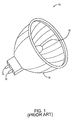
- a conventional halogen lightbulb package 10 of MR-16 outline type is shown.
- the halogen lightbulb package includes a halogen bulb 12 positioned in the center of a reflector 14, which functions to direct the light produced by the halogen bulb in a generally uniform direction.
- the package further includes a pair of output terminals 16 and 18 to receive electrical power.
- the front open face of the package may be protected with a dust cover (not shown).
- a disadvantage of the package of Fig. 1 is the use of the halogen bulb as the light source. As previously described, the fragility of the glass enclosure and the incandescent filament limits the operating life of the halogen bulb.
- LEDs Light emitting diodes
- GaN Gallium Nitride
- the blue light generated by the GaN-based LEDs can be more readily converted to produce light having a longer peak wavelength.
- light having a first peak wavelength (the "primary light”) can be converted into light having a longer peak wavelength (the “secondary light”) using a process known as fluorescence.
- the fluorescent process involves absorbing the primary light by a photoluminescent phosphor material, which excites the atoms of the phosphor material, and emitting the secondary light.
- An LED that utilizes the fluorescent process is defined herein as a "phosphor LED.”
- the peak wavelength of the secondary light will depend on the phosphor material.
- a lightbulb package can be configured to generate white output light by selecting an appropriate phosphor material for the GaN-based LED.
- U.S. Pat. No. 5,813,753 to Vriens et al. describes a light emitting device having an LED as the light source that utilizes phosphor grains dispersed in an epoxy layer to transform the color of the light emitted by the LED into a desired color.
- the phosphor grains are described as a single type of phosphor material or a mixture of different phosphor materials, depending on the desired color of the output light,
- a concern with the use of an epoxy layer that includes phosphor grains as described in Vriens et al. is the difficulty in dispensing the phosphor grains in a repeatable and uniform manner. Such difficulty leads to a population of finished devices having variable performances, i.e., the color of the output light may vary from one finished device to another.
- the present invention seeks to provide an improved light emitting device.
- the preferred embodiment can provide a lightbulb package having a phosphor LED as the light source that can generate output light of a prescribed color and a method of fabricating such a lightbulb package.
- an LED package and a method of fabricating the LED package utilize a prefabricated fluorescent member that contains a fluorescent material that can be separately tested for optical properties before assembly to ensure the proper performance of the LED package with respect to the color of the output light.
- the LED package includes one or more LED dies that operate as the light source of the package.
- the fluorescent material included in the prefabricated fluorescent member and the LED dies of the LED package are selectively chosen, so that output light generated by the LED package duplicates natural white light.
- the LED package includes four 3 volt gallium nitride-based LED dies that are individually mounted on separate reflector cups, which are attached to a leadframe.
- the LED package is configured to be interchangeable with an industry standard MR-16 halogen outline package.
- the LED package may be configured to resemble other industry standard packages, such as MRC-11, MRC-16, PAR-36, PAR-38, PAR-56 and PAR-64. In fact, the LED package may be configured in a completely different lightbulb outline package.
- LED dies are electrically connected to the terminals in a specific configuration. In one exemplary configuration, the LED dies are connected in series, so that the overall forward voltage of the package is 12 volts. In an alternative exemplary configuration, the LED dies are connected in series and parallel to create a 6 volt device.
- the exact electrical configuration of the LED dies, as well as the voltage of the LED dies, are not critical. Furthermore, the number of LED dies included in the LED package is not critical.
- encapsulant material deposited over the LED dies is an encapsulant material.
- the encapsulant material may be epoxy or other suitable transparent material.
- the encapsulant material is an optical grade silicone gel, since silicone gel can withstand exposure to high temperatures without degradation.
- silicone gel having a refractive index of 1.5 is currently available, which results in an efficient extraction of light generated by the LED dies.
- the prefabricated fluorescent member of the LED package is affixed over the encapsulant material.
- the prefabricated fluorescent member is a substantially planar disk that is optically transparent.
- the fluorescent member may be configured in another shape, such as a square or a rectangle, depending on the specification of the LED package.
- the fluorescent material contained in the prefabricated fluorescent member can be chosen to produce white light.
- the fluorescent material may include gadolinium doped, cerium activated yttrium aluminum garnet phosphor grains.
- the LED package may also include a lens that is attached to the prefabricated fluorescent member and a reflector that is positioned over the lens.
- the lens and the reflector ensure that most of the light energy generated by the LED package is output generally along a common direction.
- the lens of the LED package is a concave lens and the prefabricated fluorescent member is formed in the inner surface of the concave lens.
- the prefabricated fluorescent member conforms to the contour of the inner surface of the concave lens.
- the optical properties of the fluorescent member can be tested by examining the lens and the attached fluorescent member as a single component.
- the preferred method of fabricating the LED package includes forming a number of transparent fluorescent members.
- the fluorescent members may be substantially planar plates, such as disks. These plates may be formed by cutting sheets of silicone rubber into the desired shapes.
- the fluorescent members may be non-planar disks that conform to the inner surface of a concave lens. These non-planar disks may be formed by allowing an optically transparent material, such as silicone, polycarbonate or acrylic, to be molded onto the inner surface of a concave lens.
- the fluorescent members are tested for optical properties.
- the fluorescent members may be tested using a monochromatic standard source to activate the phosphor and then measuring the characteristics of the output from the fluorescent members, The tested fluorescent members can then be categorized for a set of optical properties.
- one or more GaN-based LED dies are mounted onto a leadframe.
- a transparent encapsulant material is deposited over the mounted LED dies.
- the encapsulant material is an optical grade silicone gel, which has a high thermal stability and has a desired refractive index for an efficient light extraction.
- a fluorescent member having a predefine set of optical properties is then placed over the encapsulant material.
- a lens is attached to the fluorescent member. This step is not applicable for the second embodiment.
- a reflector is then mounted over the lens. After the reflector has been mounted, a dust cover may be attached to the rim of the reflector to complete the LED package.
- a light source package comprising: a light source that generates primary light having a first spectral distribution; a layer of transparent material over the light source that encapsulates the light source; and a prefabricated wavelength converter attached to the layer of transparent material, the prefabricated wavelength converter being optically coupled to the light source to receive the primary light, the prefabricated wavelength converter containing a fluorescent material that emits secondary light in response to absorption of said primary light to produce a composite output light.
- the prefabricated wavelength converter may be shaped as a substantially planar rate. There may be provided a concave lens that is integrated with the prefabricated wavelength converter, the prefabricated wavelength converter having a non-planar disk shape that conforms to an inner surface of the concave lens.
- the transparent material of the layer that encapsulates the light source is preferably an optical grade silicone gel.
- Components of the package preferably define a light source package that is compatible to an industry standard package selected from a group consisting of MRC-11, MR-16, MRC-16, PAR-36, PAR-38, PAR-56 and PAR-64.
- An advantage of the preferred embodiments of the invention is that the fluorescent member can be tested prior to assembly which ensures that the finished device will have specific optical properties, thereby reducing production costs that are associated to fabrication of unwanted devices, i.e., devices that do not meet the desired specifications.
- Fig. 1 is a perspective view of a conventional halogen lightbulb package of MR-16 outline type.
- Fig. 2 is a cross-sectional diagram of an LED package in accordance with a first embodiment of the present invention.
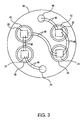
- Fig. 3 is a top view of a leadframe of the LED package of Fig. 2 in which mounted LED dies are electrically connected in a 12 volt configuration.
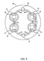
- Fig. 4 is a top view of the leadframe of the LED package of Fig. in which mounted LED dies are electrically connected in a 6 volt configuration.
- Fig. 5 is a cross-sectional diagram of an LED package in accordance with a second embodiment of the invention.
- Fig. 6 is a flow diagram of a preferred method of fabricating an LED package.
- Fig. 2 is a schematic cross-sectional view of the LED package.
- the LED package is structurally configured to resemble a conventional MR-16 halogen package, such that the LED package is interchangeable with the MR-16 package.
- the LED package utilizes four LED dies (only dies 22 and 24 are exposed in the view of Fig. 2) as the light source for the package, instead of a halogen light bulb, as is the case in the conventional MR-16 package.
- the LED package has an operating life of 10,000 hours or more, as compared to a halogen package which has a mean operating life of 500 to 4,000 hours.
- the LED package degrades by a gradual reduction in light output. Typically, at the end of the operating life of 10,000 hours, the LED package would still generate 50% of the original light output.
- the LED package 20 includes a leadframe 30 that is attached to the bottom of a cylindrical casing 32.
- the leadframe may be composed of steel or copper.
- a specular reflector 34 that directs the light generated by the LED package.
- the LED dies are gallium nitride-based LEDs (indium doped, gallium nitride on sapphire) that emit blue light when activated by an applied electrical signal.
- the configuration of the LED dies and the reflector cups on the leadframe is best illustrated in Fig.
- the reflector cups are made of a material having a coefficient of thermal expansion (CTE) that matches the LED dies.
- CTE coefficient of thermal expansion
- the reflector cups may be made of silver plated molybdenum.
- the reflector cups are swaged into the leadframe, thereby affixing the LED dies to the leadframe.
- a molybdenum disk (not shown) is attached underneath each LED die, for example, by solder. The molybdenum disk with the attached LED die is then mounted on the leadframe. This method also achieves the desired CTE matching.
- the LED dies are electrically connected to an anode terminal 44 and a cathode terminal 46 that are also attached to the leadframe.
- the LED dies 22, 24, 26 and 28 selected to be included in the LED package 20 can be of the type that enables activation at a low forward voltage of less than 3 volts each, at their maximum rated drive current, such that the four LED dies wired in series result in an overall forward voltage of a nominal 12 volts.
- the series connection is illustrated in Fig. 3. This would make the package conform to 12 volt incandescent packages.
- other arrangements of LED dies could be implemented. For example, three 4 volt LED dies could be selected and wired in series to achieve the same overall forward voltage of 12 volts.
- the exact type and number of LED dies included in the package and the configuration by which the LED dies are connected can vary, depending on the desired device to be fabricated. As an example, four 3 volt LED dies can be wired in series/parallel, as shown in Fig. 4, to achieve a 6 volt device.
- the LED dies may be electrically connected by wirebonds, as illustrated in Figs. 2, 3 and 4. As shown in Fig. 3, more than one wire may be used in order to carry the drive currents between terminals and the LED dies.
- the electrical connections shown in Figs. 2, 3 and 4 are provided by wirebonds, other electrical connection techniques common in the semiconductor industry may instead be utilized, such as flip chip solder bumping.
- the LED package 20 further includes a region 50 of encapsulant material over the LED dies.
- an optical grade material of similar refractive index must be in contact with the LED dies.
- Sapphire LED substrates commonly have a refractive index of 2.5.
- Such LEDs are commonly encapsulated with a material with a refractive index of 1.5.
- Snell's Law shows that only light emitted from the active region with an angle ⁇ of about 0.644 radians (36.9 degrees) to the normal of the interface with the encapsulant will escape the LED. In such case, a fraction of 1-Cos ⁇ or 20% of the internally generated light will escape.
- An equal amount of light is emitted from the horizontal edges of the LED die.
- the edge light from the LED die 22, 24, 26 or 28 is reflected and directed forward by the reflective cavity of the reflector cup 36, 38, 40 or 42 in which the LED die is mounted.
- the encapsulant material of the region 50 must also be able to withstand the great heat generated by the LED dies 22, 24, 26 and 28 during their operation.
- the surface temperature of the LED dies may easily reach 200 degrees Centigrade.
- epoxy would rapidly undergo thermal degradation during use, becoming progressively more yellow and absorbing much of the radiation from the LED dies, which would render the device useless.
- the encapsulant used for the region is preferably made of an optical grade silicone gel material, although other less desirable transparent materials may be used, such as epoxy. Silicones have excellent thermal stability.
- a silicone gel material having a refractive index of 1.5 is available to maximize light extraction.
- the encapsulating silicone material must be extremely soft, so that it does not exert stress on the bond wires 48 or die and break them during operation of the device 20. This would occur due to differential expansion between the silicone and the body of the device (or the molybdenum reflector 36, 38, 40 or 42).
- the CTE of these silicone materials is 80 parts per million per unit length per degree Centigrade
- the metal body for example copper
- a fluorescent plate 52 Positioned adjacent to the region 50 of encapsulant material is a fluorescent plate 52 that contains a phosphor material.
- the fluorescent plate is a prefabricated component that can be tested for optical properties, prior to the assembly of the LED package. The testing of the fluorescent plate relates to homogeneity of the phosphor contained within the plate and relates to the correct phosphor concentration.
- the fluorescent plate can be made of soft, optically clear, silicone rubber.
- the plate can be made of other optically transparent materials, such as polycarbonate or acrylic, that is dispersed with phosphor.
- the phosphor contained in the fluorescent plate will depend on the desired wavelength characteristics of the output light generated by the LED package 20.
- the plate may contain gadolinium (Gd) doped, cerium (Ce) activated yttrium aluminum garnet (YAG) phosphor grains ("Ce:YAG phosphor grains") to convert some of the blue radiation (wavelength of 460-480 nm) emitted by the LED dies 22, 24, 26 and 28 to a longer wavelength radiation.
- Gd gadolinium
- Ce cerium
- YAG yttrium aluminum garnet
- Ce:YAG phosphor grains will allow the fluorescent plate to absorb the emitted blue light and upshift the optical energy to a mean wavelength of approximately 520 nm. This resulting emission is a broadband light stretching from 480 to 620 nm.
- the combination of this emission with the remaining blue light, i.e., the unconverted emitted blue light creates a final emission with color rendering that duplicates natural white light.
- the fluorescent plate 52 may be modified by the inclusion of several other rare earth metals, such as samarium, praseodymium or other similar materials, to improve color rendering of the LED package 20.
- other phosphors may be added to create emissions in other wavelengths to modify the spectral distribution of the output light generated by the LED package.
- the exact types of fluorescent material contained within the plate are not critical to the invention.
- the fluorescent plate 52 is a substantially planar disk that resembles the shape of leadframe 30, as shown in Figs. 3 and 4.
- the fluorescent plate can be shaped to correspond to the leadframe and the configuration of the mounted LED dies.
- the fluorescent plate may be a substantially planar rectangular plate, if the LED dies of the package are arranged in a rectangular configuration on a rectangular leadframe.
- the LED package 20 further includes a lens 54 that is attached to the fluorescent plate 52 to collimate the light emitted from the device and distribute the light uniformly into the reflector 34.
- the radiation pattern from the lens is designed to fill the reflector, which is situated above the lens.
- the lens may be made of silicone.
- the lens may be made of a polycarbonate or an acrylic material.
- a dust cover 56 Situated above the lens and attached to the rim of the reflector is a dust cover 56, which serves to protect the finished device.
- FIG. 5 an exemplary LED package 60 in accordance with a second embodiment is shown.
- the LED package of Fig. 5 includes most of the components of the LED package of Fig. 2. The only significant difference is that the lens 54 and the fluorescent plate 52 included in the LED package 20 are replaced with a concave lens 62 and a molded fluorescent non-planar disk 64.
- the fluorescent non-planar disk is formed on the inside surface of the concave lens.
- the lens and the molded non-planar disk are a single prefabricated component of the LED package. That is, the lens and the non-planar disk become an integrated member that can be tested for optical properties as a unit, separately from other components of the package. Therefore, in this embodiment, the optical properties of the fluorescent non-planar disk are tested after the fluorescent non-planar disk has been formed on the inner surface of the concave lens.
- LED packages 20 and 60 of Figs. 2 and 5 have been illustrated and described as being configured as an MR-16 type outline package, these LED packages may be configured in other types of industry standard outline packages, such as MRC-11, MRC-16, PAR-36, PAR-38, PAT-56 and PAR-64. In fact, the LED packages may be configured in a completely different outline with any number of LED dies that are arranged in any configuration.
- the fluorescent members contain a phosphor material that is distributed within the fluorescent members.
- the fluorescent members are made of silicone rubber and contain Ce:YAG phosphor grains.
- the fluorescent members are shaped plates that are formed by cutting sheets of optically clear material that contains the phosphor material into a shape that corresponds to the axial configuration of the LED packages to be fabricated. For example, the finished plates may be formed in the shape of disks.
- the fluorescent members are shaped as non-planar disks that conform to the inner surfaces of concave lenses.
- the fluorescent members are formed by molding an optically transparent material, such as polycarbonate or acrylic, that has been dispersed with a fluorescent material into the non-planar disk shape using the contours of the concave lens.
- the fluorescent members are tested for optical properties.
- the fluorescent members may be tested using a monochromatic standard source to activate the phosphor and then measuring the output from the fluorescent members.
- the tested fluorescent members can then be "binned" or categorized for a set of optical properties.
- Those fluorescent members exhibiting similar properties can be used to produce finished devices of very similar optical properties.
- devices can be produced to meet specific customer needs with respect to color temperature and output spectrum. Since the optical properties are known prior to the production of the devices, unwanted devices with optical characteristics that do not meet the desired specifications are avoided, thereby reducing production costs.
- one or more GaN-based LED dies are mounted onto a leadframe.
- a transparent encapsulant material is deposited over the LED dies.
- a silicone gel material is used as the encapsulant, since the silicone gel material has excellent thermal characteristics and also has a desired refractive index.
- a tested fluorescent member having specific optical properties is attached above the encapsulant material, during step 74. Clear silicone adhesives may be used to attach the fluorescent member to the encapsulant material. Alternatively, the fluorescent member may simply be pressed firmly against the encapsulant material.
- a lens is attached to the fluorescent member.
- the lens may be attached to the fluorescent member using silicone adhesives or by pressing the lens firmly against the fluorescent member. In the second embodiment, where the lens and the fluorescent member is a single prefabricated component, this step is not applicable.
- a reflector is mounted over the lens. After the reflector has been mounted, a dust cover may be attached to the rim of the reflector, during step 80.
Abstract
Description
- The invention relates generally to a light emitting device, for example a lightbulb package that utilizes a phosphor light emitting diode as the light source.
- Common lightbulb packages utilize a light source that includes an incandescent filament within a glass enclosure. However, these glass enclosures are fragile and, as such, can easily break even when subjected to only a moderate impact. In addition, the incandescent filaments themselves are fragile and tend to gradually degrade during use, such that the useful light output generated by the filaments decreases over time. The increasing fragility of the filament with age eventually leads to breakage. Typical incandescent lightbulbs have a mean life of 500 to 4,000 hours, which means that half of a population of lightbulbs will fail in that time because of filament breakage.
- With reference to Fig. 1, a conventional
halogen lightbulb package 10 of MR-16 outline type is shown. The halogen lightbulb package includes ahalogen bulb 12 positioned in the center of areflector 14, which functions to direct the light produced by the halogen bulb in a generally uniform direction. The package further includes a pair ofoutput terminals - Confronted with the above disadvantage, the use of light emitting diodes as a potential light source in a lightbulb package has been examined. Light emitting diodes (LEDs) are well-known solid state devices that can generate light having a peak wavelength in a specific region of the light spectrum. Traditionally, the most efficient LEDs emit light having a peak wavelength in the red region of the light spectrum, i.e., red light. However, a type of LED based on Gallium Nitride (GaN) has recently been developed that can efficiently emit light having a peak wavelength in the blue region of the spectrum, i.e., blue light. This new type of LED can provide significantly brighter output light than traditional LEDs.
- In addition, since blue light has a shorter peak wavelength than red light, the blue light generated by the GaN-based LEDs can be more readily converted to produce light having a longer peak wavelength. It is well known in the art that light having a first peak wavelength (the "primary light") can be converted into light having a longer peak wavelength (the "secondary light") using a process known as fluorescence. The fluorescent process involves absorbing the primary light by a photoluminescent phosphor material, which excites the atoms of the phosphor material, and emitting the secondary light. An LED that utilizes the fluorescent process is defined herein as a "phosphor LED." The peak wavelength of the secondary light will depend on the phosphor material. The combined light of unconverted primary light and the secondary light produces the output light of the phosphor LED. Thus, the particular color of the output light will depend on the spectral distributions of the primary and second lights. Consequently, a lightbulb package can be configured to generate white output light by selecting an appropriate phosphor material for the GaN-based LED.
- U.S. Pat. No. 5,813,753 to Vriens et al. describes a light emitting device having an LED as the light source that utilizes phosphor grains dispersed in an epoxy layer to transform the color of the light emitted by the LED into a desired color. The phosphor grains are described as a single type of phosphor material or a mixture of different phosphor materials, depending on the desired color of the output light, A concern with the use of an epoxy layer that includes phosphor grains as described in Vriens et al. is the difficulty in dispensing the phosphor grains in a repeatable and uniform manner. Such difficulty leads to a population of finished devices having variable performances, i.e., the color of the output light may vary from one finished device to another.
- The present invention seeks to provide an improved light emitting device.
- According to an aspect of the present invention, there is provided a method of fabricating a light emitting device as specified in claim 1.
- According to another aspect of the present invention there is provided a light emitting device as specified in claim 7.
- The preferred embodiment can provide a lightbulb package having a phosphor LED as the light source that can generate output light of a prescribed color and a method of fabricating such a lightbulb package.
- In an embodiment, an LED package and a method of fabricating the LED package utilize a prefabricated fluorescent member that contains a fluorescent material that can be separately tested for optical properties before assembly to ensure the proper performance of the LED package with respect to the color of the output light. The LED package includes one or more LED dies that operate as the light source of the package. Preferably, the fluorescent material included in the prefabricated fluorescent member and the LED dies of the LED package are selectively chosen, so that output light generated by the LED package duplicates natural white light.
- In a first embodiment of the invention, the LED package includes four 3 volt gallium nitride-based LED dies that are individually mounted on separate reflector cups, which are attached to a leadframe. In this embodiment, the LED package is configured to be interchangeable with an industry standard MR-16 halogen outline package. However, the LED package may be configured to resemble other industry standard packages, such as MRC-11, MRC-16, PAR-36, PAR-38, PAR-56 and PAR-64. In fact, the LED package may be configured in a completely different lightbulb outline package.
- Also attached to the leadframe are output terminals that provide electrical power to the LED dies. The LED dies are electrically connected to the terminals in a specific configuration. In one exemplary configuration, the LED dies are connected in series, so that the overall forward voltage of the package is 12 volts. In an alternative exemplary configuration, the LED dies are connected in series and parallel to create a 6 volt device. The exact electrical configuration of the LED dies, as well as the voltage of the LED dies, are not critical. Furthermore, the number of LED dies included in the LED package is not critical.
- Preferably, deposited over the LED dies is an encapsulant material. The encapsulant material may be epoxy or other suitable transparent material. Preferably, the encapsulant material is an optical grade silicone gel, since silicone gel can withstand exposure to high temperatures without degradation. In addition, silicone gel having a refractive index of 1.5 is currently available, which results in an efficient extraction of light generated by the LED dies.
- The prefabricated fluorescent member of the LED package is affixed over the encapsulant material. In this embodiment, the prefabricated fluorescent member is a substantially planar disk that is optically transparent. However, the fluorescent member may be configured in another shape, such as a square or a rectangle, depending on the specification of the LED package. As previously noted, the fluorescent material contained in the prefabricated fluorescent member can be chosen to produce white light. As an example, the fluorescent material may include gadolinium doped, cerium activated yttrium aluminum garnet phosphor grains.
- The LED package may also include a lens that is attached to the prefabricated fluorescent member and a reflector that is positioned over the lens. The lens and the reflector ensure that most of the light energy generated by the LED package is output generally along a common direction.
- In a second embodiment of the invention, the lens of the LED package is a concave lens and the prefabricated fluorescent member is formed in the inner surface of the concave lens. As such, the prefabricated fluorescent member conforms to the contour of the inner surface of the concave lens. In this embodiment, the optical properties of the fluorescent member can be tested by examining the lens and the attached fluorescent member as a single component.
- The preferred method of fabricating the LED package includes forming a number of transparent fluorescent members.
- In a first embodiment, the fluorescent members may be substantially planar plates, such as disks. These plates may be formed by cutting sheets of silicone rubber into the desired shapes. In a second embodiment, the fluorescent members may be non-planar disks that conform to the inner surface of a concave lens. These non-planar disks may be formed by allowing an optically transparent material, such as silicone, polycarbonate or acrylic, to be molded onto the inner surface of a concave lens. Next, the fluorescent members are tested for optical properties. As an example, the fluorescent members may be tested using a monochromatic standard source to activate the phosphor and then measuring the characteristics of the output from the fluorescent members, The tested fluorescent members can then be categorized for a set of optical properties.
- Preferably, after the fluorescent members are tested, one or more GaN-based LED dies are mounted onto a leadframe. Next, a transparent encapsulant material is deposited over the mounted LED dies. Preferably, the encapsulant material is an optical grade silicone gel, which has a high thermal stability and has a desired refractive index for an efficient light extraction. A fluorescent member having a predefine set of optical properties is then placed over the encapsulant material. Next, a lens is attached to the fluorescent member. This step is not applicable for the second embodiment. A reflector is then mounted over the lens. After the reflector has been mounted, a dust cover may be attached to the rim of the reflector to complete the LED package.
- According to another aspect of the present invention there is provided a light source package comprising: a light source that generates primary light having a first spectral distribution; a layer of transparent material over the light source that encapsulates the light source; and a prefabricated wavelength converter attached to the layer of transparent material, the prefabricated wavelength converter being optically coupled to the light source to receive the primary light, the prefabricated wavelength converter containing a fluorescent material that emits secondary light in response to absorption of said primary light to produce a composite output light.
- The prefabricated wavelength converter may be shaped as a substantially planar rate. There may be provided a concave lens that is integrated with the prefabricated wavelength converter, the prefabricated wavelength converter having a non-planar disk shape that conforms to an inner surface of the concave lens. The transparent material of the layer that encapsulates the light source is preferably an optical grade silicone gel.
- Components of the package, preferably define a light source package that is compatible to an industry standard package selected from a group consisting of MRC-11, MR-16, MRC-16, PAR-36, PAR-38, PAR-56 and PAR-64.
- An advantage of the preferred embodiments of the invention is that the fluorescent member can be tested prior to assembly which ensures that the finished device will have specific optical properties, thereby reducing production costs that are associated to fabrication of unwanted devices, i.e., devices that do not meet the desired specifications.
- An embodiment of the present invention is described below, by way of example only, with reference to the accompanying drawings, in which:
- Fig. 1 is a perspective view of a conventional halogen lightbulb package of MR-16 outline type.
- Fig. 2 is a cross-sectional diagram of an LED package in accordance with a first embodiment of the present invention.
- Fig. 3 is a top view of a leadframe of the LED package of Fig. 2 in which mounted LED dies are electrically connected in a 12 volt configuration.
- Fig. 4 is a top view of the leadframe of the LED package of Fig. in which mounted LED dies are electrically connected in a 6 volt configuration.
- Fig. 5 is a cross-sectional diagram of an LED package in accordance with a second embodiment of the invention.
- Fig. 6 is a flow diagram of a preferred method of fabricating an LED package.
- With reference to Fig. 2, an
exemplary LED package 20 in accordance with a first embodiment is shown. Fig. 2 is a schematic cross-sectional view of the LED package. The LED package is structurally configured to resemble a conventional MR-16 halogen package, such that the LED package is interchangeable with the MR-16 package. However, the LED package utilizes four LED dies (only dies 22 and 24 are exposed in the view of Fig. 2) as the light source for the package, instead of a halogen light bulb, as is the case in the conventional MR-16 package. The LED package has an operating life of 10,000 hours or more, as compared to a halogen package which has a mean operating life of 500 to 4,000 hours. Furthermore, unlike halogen packages which fail by filament breakage. the LED package degrades by a gradual reduction in light output. Typically, at the end of the operating life of 10,000 hours, the LED package would still generate 50% of the original light output. - The
LED package 20 includes aleadframe 30 that is attached to the bottom of acylindrical casing 32. As an example, the leadframe may be composed of steel or copper. Also attached to the casing is aspecular reflector 34 that directs the light generated by the LED package. Referring now to Figs. 2 and 3, four LED dies 22, 24, 26 and 28 of the package are affixed to the leadframe via reflector cups 36, 38, 40 and 42, respectively. Preferably, the LED dies are gallium nitride-based LEDs (indium doped, gallium nitride on sapphire) that emit blue light when activated by an applied electrical signal. The configuration of the LED dies and the reflector cups on the leadframe is best illustrated in Fig. 3, which is a top view of the leadframe. The LED dies are mounted into the cavities of the reflector cups, as most clearly shown in Fig. 2. Preferably, the reflector cups are made of a material having a coefficient of thermal expansion (CTE) that matches the LED dies. As an example, the reflector cups may be made of silver plated molybdenum. The reflector cups are swaged into the leadframe, thereby affixing the LED dies to the leadframe. In an alternative embodiment, a molybdenum disk (not shown) is attached underneath each LED die, for example, by solder. The molybdenum disk with the attached LED die is then mounted on the leadframe. This method also achieves the desired CTE matching. The LED dies are electrically connected to ananode terminal 44 and acathode terminal 46 that are also attached to the leadframe. - The LED dies 22, 24, 26 and 28 selected to be included in the
LED package 20 can be of the type that enables activation at a low forward voltage of less than 3 volts each, at their maximum rated drive current, such that the four LED dies wired in series result in an overall forward voltage of a nominal 12 volts. The series connection is illustrated in Fig. 3. This would make the package conform to 12 volt incandescent packages. However, if a different series voltage is required, other arrangements of LED dies could be implemented. For example, three 4 volt LED dies could be selected and wired in series to achieve the same overall forward voltage of 12 volts. The exact type and number of LED dies included in the package and the configuration by which the LED dies are connected can vary, depending on the desired device to be fabricated. As an example, four 3 volt LED dies can be wired in series/parallel, as shown in Fig. 4, to achieve a 6 volt device. The LED dies may be electrically connected by wirebonds, as illustrated in Figs. 2, 3 and 4. As shown in Fig. 3, more than one wire may be used in order to carry the drive currents between terminals and the LED dies. Although the electrical connections shown in Figs. 2, 3 and 4 are provided by wirebonds, other electrical connection techniques common in the semiconductor industry may instead be utilized, such as flip chip solder bumping. - Preferably, the size of the LED dies 22, 24, 26 and 28 is such that the photometric power is of a useful range. This may require the size of the LED die to be 2.89 square millimeter, which would result in a current density on the die greater than 70 amps per square centimeter. For example, if the photometric power of these LED dies is 5 lumens (per watt of input power) and the input power to an assembly of four dies is 24 watts (12 volts at 2 amps), then the total optical output power is 5 x 24 = 120 lumens of blue light. When this is modified into white light, a typical output in white light is raised by a factor of 1.9, which results in a final white light output of 120 x 1.9 = 228 lumens.
- Turning back to Fig. 2, the
LED package 20 further includes aregion 50 of encapsulant material over the LED dies. To extract the maximum amount of light from the LED dies 22, 24, 26 and 28, an optical grade material of similar refractive index must be in contact with the LED dies. Sapphire LED substrates commonly have a refractive index of 2.5. Such LEDs are commonly encapsulated with a material with a refractive index of 1.5. Application of Snell's Law shows that only light emitted from the active region with an angle of about 0.644 radians (36.9 degrees) to the normal of the interface with the encapsulant will escape the LED. In such case, a fraction of 1-Cos or 20% of the internally generated light will escape. An equal amount of light is emitted from the horizontal edges of the LED die. The edge light from the LED die 22, 24, 26 or 28 is reflected and directed forward by the reflective cavity of thereflector cup - In addition to the refractive index issue, the encapsulant material of the
region 50 must also be able to withstand the great heat generated by the LED dies 22, 24, 26 and 28 during their operation. The surface temperature of the LED dies may easily reach 200 degrees Centigrade. Under such circumstances, epoxy would rapidly undergo thermal degradation during use, becoming progressively more yellow and absorbing much of the radiation from the LED dies, which would render the device useless. For the above reasons, the encapsulant used for the region is preferably made of an optical grade silicone gel material, although other less desirable transparent materials may be used, such as epoxy. Silicones have excellent thermal stability. In addition, a silicone gel material having a refractive index of 1.5 is available to maximize light extraction. However, the encapsulating silicone material must be extremely soft, so that it does not exert stress on thebond wires 48 or die and break them during operation of thedevice 20. This would occur due to differential expansion between the silicone and the body of the device (or themolybdenum reflector - Positioned adjacent to the
region 50 of encapsulant material is afluorescent plate 52 that contains a phosphor material. The fluorescent plate is a prefabricated component that can be tested for optical properties, prior to the assembly of the LED package. The testing of the fluorescent plate relates to homogeneity of the phosphor contained within the plate and relates to the correct phosphor concentration. As an example, the fluorescent plate can be made of soft, optically clear, silicone rubber. However, the plate can be made of other optically transparent materials, such as polycarbonate or acrylic, that is dispersed with phosphor. The phosphor contained in the fluorescent plate will depend on the desired wavelength characteristics of the output light generated by theLED package 20. As an example, the plate may contain gadolinium (Gd) doped, cerium (Ce) activated yttrium aluminum garnet (YAG) phosphor grains ("Ce:YAG phosphor grains") to convert some of the blue radiation (wavelength of 460-480 nm) emitted by the LED dies 22, 24, 26 and 28 to a longer wavelength radiation. The use of Ce:YAG phosphor grains will allow the fluorescent plate to absorb the emitted blue light and upshift the optical energy to a mean wavelength of approximately 520 nm. This resulting emission is a broadband light stretching from 480 to 620 nm. The combination of this emission with the remaining blue light, i.e., the unconverted emitted blue light, creates a final emission with color rendering that duplicates natural white light. - In the above example, the
fluorescent plate 52 may be modified by the inclusion of several other rare earth metals, such as samarium, praseodymium or other similar materials, to improve color rendering of theLED package 20. In addition, other phosphors may be added to create emissions in other wavelengths to modify the spectral distribution of the output light generated by the LED package. The exact types of fluorescent material contained within the plate are not critical to the invention. - In the illustrated embodiment, the
fluorescent plate 52 is a substantially planar disk that resembles the shape ofleadframe 30, as shown in Figs. 3 and 4. However, in other embodiments where the LED dies 22, 24, 26 and 28 are arranged in a different configuration such that the leadframe is non-circular, the fluorescent plate can be shaped to correspond to the leadframe and the configuration of the mounted LED dies. For example, the fluorescent plate may be a substantially planar rectangular plate, if the LED dies of the package are arranged in a rectangular configuration on a rectangular leadframe. - The
LED package 20 further includes alens 54 that is attached to thefluorescent plate 52 to collimate the light emitted from the device and distribute the light uniformly into thereflector 34. The radiation pattern from the lens is designed to fill the reflector, which is situated above the lens. As an example, the lens may be made of silicone. Alternatively, the lens may be made of a polycarbonate or an acrylic material. Situated above the lens and attached to the rim of the reflector is adust cover 56, which serves to protect the finished device. - Turning now to Fig. 5, an
exemplary LED package 60 in accordance with a second embodiment is shown. The LED package of Fig. 5 includes most of the components of the LED package of Fig. 2. The only significant difference is that thelens 54 and thefluorescent plate 52 included in theLED package 20 are replaced with aconcave lens 62 and a molded fluorescentnon-planar disk 64. The fluorescent non-planar disk is formed on the inside surface of the concave lens. Thus, the lens and the molded non-planar disk are a single prefabricated component of the LED package. That is, the lens and the non-planar disk become an integrated member that can be tested for optical properties as a unit, separately from other components of the package. Therefore, in this embodiment, the optical properties of the fluorescent non-planar disk are tested after the fluorescent non-planar disk has been formed on the inner surface of the concave lens. - Although the LED packages 20 and 60 of Figs. 2 and 5 have been illustrated and described as being configured as an MR-16 type outline package, these LED packages may be configured in other types of industry standard outline packages, such as MRC-11, MRC-16, PAR-36, PAR-38, PAT-56 and PAR-64. In fact, the LED packages may be configured in a completely different outline with any number of LED dies that are arranged in any configuration.
- A method of fabricating an LED package, such as the LED packages 20 and 60 of Figs. 2 and 5, will be described with reference to Fig. 6. At
step 66, a number of fluorescent members that are optically transparent are formed. The fluorescent members contain a phosphor material that is distributed within the fluorescent members. Preferably, the fluorescent members are made of silicone rubber and contain Ce:YAG phosphor grains. In a first embodiment, the fluorescent members are shaped plates that are formed by cutting sheets of optically clear material that contains the phosphor material into a shape that corresponds to the axial configuration of the LED packages to be fabricated. For example, the finished plates may be formed in the shape of disks. In a second embodiment, the fluorescent members are shaped as non-planar disks that conform to the inner surfaces of concave lenses. In this embodiment, the fluorescent members are formed by molding an optically transparent material, such as polycarbonate or acrylic, that has been dispersed with a fluorescent material into the non-planar disk shape using the contours of the concave lens. Duringstep 68, the fluorescent members are tested for optical properties. As an example, the fluorescent members may be tested using a monochromatic standard source to activate the phosphor and then measuring the output from the fluorescent members. The tested fluorescent members can then be "binned" or categorized for a set of optical properties. Those fluorescent members exhibiting similar properties can be used to produce finished devices of very similar optical properties. Thus, devices can be produced to meet specific customer needs with respect to color temperature and output spectrum. Since the optical properties are known prior to the production of the devices, unwanted devices with optical characteristics that do not meet the desired specifications are avoided, thereby reducing production costs. - At
step 70, one or more GaN-based LED dies are mounted onto a leadframe. Duringstep 72, a transparent encapsulant material is deposited over the LED dies. Preferably, a silicone gel material is used as the encapsulant, since the silicone gel material has excellent thermal characteristics and also has a desired refractive index. Next, a tested fluorescent member having specific optical properties is attached above the encapsulant material, duringstep 74. Clear silicone adhesives may be used to attach the fluorescent member to the encapsulant material. Alternatively, the fluorescent member may simply be pressed firmly against the encapsulant material. Next, duringstep 76, a lens is attached to the fluorescent member. Similar to the attachment of the fluorescent member to the encapsulant material, the lens may be attached to the fluorescent member using silicone adhesives or by pressing the lens firmly against the fluorescent member. In the second embodiment, where the lens and the fluorescent member is a single prefabricated component, this step is not applicable. Duringstep 78, a reflector is mounted over the lens. After the reflector has been mounted, a dust cover may be attached to the rim of the reflector, duringstep 80. - The disclosures in United States patent application No. 09/390,006, from which this application claims priority, and in the abstract accompanying this application are incorporated herein by reference.
Claims (13)
- A method of fabricating a light emitting device, including the steps of:forming (66) an optical member that contains a fluorescent material;testing (66) said formed optical member for optical properties before assembling said optical member with other components of said light emitting device; andaffixing (70-80) said optical member onto an assembly that includes a light emitting diode (22-28), said optical member being positioned with respect to said light emitting diode to generate a secondary emission by converting a portion of light emitted from said light emitting diode to produce a composite output light, said composite output light being composed of the unconverted portion of said light emitted from said light emitting diode and said secondary emission.
- A method as in claim 1, wherein said step of forming said optical member includes forming a transparent plate that contains said fluorescent material, said transparent plate being substantially planar, or the step of conforming said optical member to a surface of a lens of said light emitting device such that said optical member becomes an integral part of said lens.
- A method as in any preceding claim, comprising the step of depositing (72) an encapsulant optical grade silicone gel onto said light emitting diode of said assembly prior to said step of affixing said optical member onto said assembly.
- A method as in any preceding claim, comprising the step of attaching (76) a lens onto said assembly to collimate said light emitted from said light emitting diode of said assembly.
- A method as in any preceding claim, comprising the step of attaching (78) a reflector onto said assembly after said step of affixing said optical member onto said assembly.
- A method as in any preceding claim, wherein a plurality of light emitting diodes are mounted onto said assembly, and are electrically connected such that an overall forward voltage of the device is one of six volts and twelve volts.
- A light emitting device comprising:light-generating means (22-28) for emitting primary light having a first spectral distribution in response to an applied electrical signal;a fluorescent member (52, 64) optically coupled to said light-generating means, said fluorescent member being optically transparent and containing a phosphor material such that secondary light having a second spectral distribution is emitted when a portion of said primary light is absorbed by said phosphor material, said primary light and said secondary light defining a spectral distribution of output light generated by said device; andconnecting means (50) for connecting said fluorescent member to said light-generating means.
- A device as in claim 7, wherein said fluorescent member (52) is a substantially planar plate (52) that is positioned with respect to said light-generating means (22-28) such that a face of said plate is generally perpendicular to a direction of said primary light emitted from said light-generating means.
- A device as in claim 7 or 8, comprising a lens (54, 62) integrally attached to said fluorescent member (52, 64) said fluorescent member conforming to a surface of said lens such that said fluorescent member and said lens are an integrated unit.
- A device as in claim 7, 8 or 9, wherein said phosphor material contained in said fluorescent member (54, 64) includes gadolinium doped, cerium activated yttrium aluminum garnet phosphor grains that are dispersed within said fluorescent member.
- A device as in any one of claims 7 to 10, wherein said connecting means (50) includes an optical grade silicone gel that encapsulates said light-generating means, said optical grade silicone gel being positioned between said prefabricated transparent member and said light-generating means.
- A device as in any one of claims 7 to 11, wherein said light-generating means (22-28) includes a gallium nitride-based light emitting diode on a plurality of gallium nitride-based light emitting diodes (22-28) electrically connected such that a forward voltage of said device is one of six volts and twelve volts.
- A device as in any one of claims 7 to 12, comprising a reflector (34) optically coupled to said fluorescent member.
Applications Claiming Priority (2)
| Application Number | Priority Date | Filing Date | Title |
|---|---|---|---|
| US390006 | 1999-09-03 | ||
| US09/390,006 US6504301B1 (en) | 1999-09-03 | 1999-09-03 | Non-incandescent lightbulb package using light emitting diodes |
Publications (3)
| Publication Number | Publication Date |
|---|---|
| EP1081771A2 true EP1081771A2 (en) | 2001-03-07 |
| EP1081771A3 EP1081771A3 (en) | 2002-03-13 |
| EP1081771B1 EP1081771B1 (en) | 2011-06-01 |
Family
ID=23540657
Family Applications (1)
| Application Number | Title | Priority Date | Filing Date |
|---|---|---|---|
| EP00307565A Expired - Lifetime EP1081771B1 (en) | 1999-09-03 | 2000-09-01 | Method of fabricating a light emitting device |
Country Status (3)
| Country | Link |
|---|---|
| US (1) | US6504301B1 (en) |
| EP (1) | EP1081771B1 (en) |
| JP (2) | JP5116912B2 (en) |
Cited By (77)
| Publication number | Priority date | Publication date | Assignee | Title |
|---|---|---|---|---|
| GB2372149A (en) * | 2001-02-12 | 2002-08-14 | Arima Optoelectronics Corp | Manufacture of white LEDs having uniform colour temperature |
| EP1249873A2 (en) * | 2001-04-09 | 2002-10-16 | Kabushiki Kaisha Toshiba | Light emitting device |
| WO2003023857A2 (en) * | 2001-09-13 | 2003-03-20 | Lucea Ag | Led-luminous panel and carrier plate |
| WO2003036159A1 (en) * | 2001-10-25 | 2003-05-01 | Tir Systems Ltd. | Solid state continuous sealed clean room light fixture |
| WO2003038334A1 (en) * | 2001-10-24 | 2003-05-08 | Koenecke Dirk | Luminous element |
| EP1363335A2 (en) * | 2002-05-15 | 2003-11-19 | Sumitomo Electric Industries, Ltd. | White color light emitting device |
| EP1396023A1 (en) * | 2001-06-15 | 2004-03-10 | Lednium Pty Limited | A method of producing a lamp |
| EP1403936A2 (en) * | 2002-09-26 | 2004-03-31 | Citizen Electronics Co., Ltd. | Method for manufacturing a light emitting device |
| EP1408559A2 (en) * | 2002-10-07 | 2004-04-14 | Citizen Electronics Co., Ltd. | White light emitting device |
| WO2004077578A2 (en) * | 2003-02-28 | 2004-09-10 | Osram Opto Semiconductors Gmbh | Lighting module based on light-emitting diodes and method for the production thereof |
| WO2004112152A2 (en) | 2003-06-18 | 2004-12-23 | Leising Guenther | Method for the production of white leds, and white led light source |
| WO2005062098A1 (en) * | 2003-12-02 | 2005-07-07 | 3M Innovative Properties Company | Light source using a plurality of leds, and method of assembling the same |
| EP1526580A3 (en) * | 2003-09-17 | 2006-03-08 | Stanley Electric Co., Ltd. | Light source and vehicle lamp |
| DE102004060475A1 (en) * | 2004-12-16 | 2006-07-06 | Hella Kgaa Hueck & Co. | Head light for vehicles has light-converting luminescent material is designed as light-converting luminescent coating which exhibits given contour and a defined irradiancy is generated on the light-converting luminescent material coating |
| WO2006071391A1 (en) * | 2004-12-29 | 2006-07-06 | 3M Innovative Properties Company | Illumination system using multiple light sources with integrating tunnel and projection systems using same |
| WO2006136965A2 (en) * | 2005-06-23 | 2006-12-28 | Koninklijke Philips Electronics N.V. | A light-emitting device and method for its design |
| US7163327B2 (en) | 2002-12-02 | 2007-01-16 | 3M Innovative Properties Company | Illumination system using a plurality of light sources |
| US7189983B2 (en) | 2003-12-02 | 2007-03-13 | 3M Innovative Properties Company | LED modifying apparatus and method |
| US7224000B2 (en) | 2002-08-30 | 2007-05-29 | Lumination, Llc | Light emitting diode component |
| WO2007075742A2 (en) | 2005-12-21 | 2007-07-05 | Cree Led Lighting Solutions, Inc. | Lighting device |
| EP1808640A1 (en) * | 2004-11-01 | 2007-07-18 | Nikon Corporation | Light emitting device |
| WO2007126561A1 (en) * | 2006-03-28 | 2007-11-08 | Lumination Llc | Q silicone-containing composition, optoelectronic encapsulant thereof and device thereof |
| US7312477B2 (en) | 2003-06-13 | 2007-12-25 | Stanley Electric Co., Ltd. | Led lamp for light source |
| WO2007067758A3 (en) * | 2005-12-08 | 2008-01-10 | Univ California | High efficiency light emitting diode (led) |
| WO2008050783A1 (en) * | 2006-10-19 | 2008-05-02 | Panasonic Corporation | Light-emitting device and display unit and lighting unit using the same |
| DE102006062066A1 (en) * | 2006-12-29 | 2008-07-03 | Osram Opto Semiconductors Gmbh | Lens arrangement for light emitting diode display device, has lens with lens surface and optical axis, which penetrates lens surface of lens |
| EP2007576A1 (en) * | 2006-03-15 | 2008-12-31 | KDT Co.Ltd. | Photoluminescent sheet |
| US7484872B2 (en) | 2003-10-24 | 2009-02-03 | Stanley Electric Co., Ltd. | Vehicle lamp |
| WO2009016563A1 (en) * | 2007-08-02 | 2009-02-05 | Koninklijke Philips Electronics N.V. | Reflector and light output device |
| WO2009093163A2 (en) * | 2008-01-22 | 2009-07-30 | Koninklijke Philips Electronics N.V. | Illumination device with led and a transmissive support comprising a luminescent material |
| US7648257B2 (en) | 2006-04-21 | 2010-01-19 | Cree, Inc. | Light emitting diode packages |
| US7665862B2 (en) | 2006-09-12 | 2010-02-23 | Cree, Inc. | LED lighting fixture |
| US7687813B2 (en) | 2006-11-15 | 2010-03-30 | The Regents Of The University Of California | Standing transparent mirrorless light emitting diode |
| WO2010035176A1 (en) * | 2008-09-23 | 2010-04-01 | Koninklijke Philips Electronics N.V. | Illumination device with electrical variable scattering element |
| US7719020B2 (en) | 2005-06-17 | 2010-05-18 | The Regents Of The University Of California | (Al,Ga,In)N and ZnO direct wafer bonded structure for optoelectronic applications, and its fabrication method |
| US7722220B2 (en) | 2006-05-05 | 2010-05-25 | Cree Led Lighting Solutions, Inc. | Lighting device |
| US7768023B2 (en) | 2005-10-14 | 2010-08-03 | The Regents Of The University Of California | Photonic structures for efficient light extraction and conversion in multi-color light emitting devices |
| US7766508B2 (en) | 2006-09-12 | 2010-08-03 | Cree, Inc. | LED lighting fixture |
| US7777166B2 (en) | 2006-04-21 | 2010-08-17 | Cree, Inc. | Solid state luminaires for general illumination including closed loop feedback control |
| US7781789B2 (en) | 2006-11-15 | 2010-08-24 | The Regents Of The University Of California | Transparent mirrorless light emitting diode |
| US7800121B2 (en) | 2002-08-30 | 2010-09-21 | Lumination Llc | Light emitting diode component |
| WO2010123432A1 (en) * | 2009-04-20 | 2010-10-28 | Prismalence Ab | Light source for a light fitting comprising a reflector |
| US7824070B2 (en) | 2007-03-22 | 2010-11-02 | Cree, Inc. | LED lighting fixture |
| US7842960B2 (en) | 2006-09-06 | 2010-11-30 | Lumination Llc | Light emitting packages and methods of making same |
| US7868341B2 (en) | 2007-06-27 | 2011-01-11 | The Regents Of The University Of California | Optical designs for high-efficacy white-light emitting diodes |
| US7926300B2 (en) | 2005-11-18 | 2011-04-19 | Cree, Inc. | Adaptive adjustment of light output of solid state lighting panels |
| EP1455398A3 (en) * | 2003-03-03 | 2011-05-25 | Toyoda Gosei Co., Ltd. | Light emitting device comprising a phosphor layer and method of making same |
| US7952270B2 (en) | 2005-07-14 | 2011-05-31 | Koninklijke Philips Electronics N.V. | Electroluminescent device |
| US7994527B2 (en) | 2005-11-04 | 2011-08-09 | The Regents Of The University Of California | High light extraction efficiency light emitting diode (LED) |
| US8042971B2 (en) | 2007-06-27 | 2011-10-25 | Cree, Inc. | Light emitting device (LED) lighting systems for emitting light in multiple directions and related methods |
| US8120240B2 (en) | 2005-01-10 | 2012-02-21 | Cree, Inc. | Light emission device and method utilizing multiple emitters |
| US8125137B2 (en) | 2005-01-10 | 2012-02-28 | Cree, Inc. | Multi-chip light emitting device lamps for providing high-CRI warm white light and light fixtures including the same |
| EP2437318A2 (en) * | 2007-08-03 | 2012-04-04 | Panasonic Corporation | Light-Emitting Device |
| US8227820B2 (en) | 2005-02-09 | 2012-07-24 | The Regents Of The University Of California | Semiconductor light-emitting device |
| US8240875B2 (en) | 2008-06-25 | 2012-08-14 | Cree, Inc. | Solid state linear array modules for general illumination |
| US8258527B2 (en) | 2008-06-09 | 2012-09-04 | Stanley Electric Co., Ltd. | Lighting device and semiconductor light source device |
| US8258682B2 (en) | 2007-02-12 | 2012-09-04 | Cree, Inc. | High thermal conductivity packaging for solid state light emitting apparatus and associated assembling methods |
| US8278846B2 (en) | 2005-11-18 | 2012-10-02 | Cree, Inc. | Systems and methods for calibrating solid state lighting panels |
| WO2012148585A1 (en) * | 2011-04-25 | 2012-11-01 | Terralux, Inc. | Light emitting diode replacement lamp |
| KR20130071034A (en) * | 2011-12-20 | 2013-06-28 | 엘지이노텍 주식회사 | Lighting device |
| US8514210B2 (en) | 2005-11-18 | 2013-08-20 | Cree, Inc. | Systems and methods for calibrating solid state lighting panels using combined light output measurements |
| US8823290B2 (en) | 2003-09-12 | 2014-09-02 | Terralux, Inc. | Light emitting diode replacement lamp |
| US8860051B2 (en) | 2006-11-15 | 2014-10-14 | The Regents Of The University Of California | Textured phosphor conversion layer light emitting diode |
| EP2803898A1 (en) * | 2004-05-05 | 2014-11-19 | Rensselaer Polytechnic Institute | A light-emitting apparatus |
| US8920676B2 (en) | 2005-09-30 | 2014-12-30 | The Regents Of The University Of California | Cerium based phosphor materials for solid-state lighting applications |
| US9447945B2 (en) | 2004-05-05 | 2016-09-20 | Rensselaer Polytechnic Institute | Lighting source using solid state emitter and phosphor materials |
| US10018346B2 (en) | 2006-04-18 | 2018-07-10 | Cree, Inc. | Lighting device and lighting method |
| US10030824B2 (en) | 2007-05-08 | 2018-07-24 | Cree, Inc. | Lighting device and lighting method |
| EP1528603B1 (en) * | 2003-10-31 | 2018-08-15 | OSRAM Opto Semiconductors GmbH | Light emitting diode |
| EP3392917A1 (en) * | 2012-09-13 | 2018-10-24 | Quarkstar LLC | Light-emitting device with remote scattering element and total internal reflection extractor element |
| US10340424B2 (en) | 2002-08-30 | 2019-07-02 | GE Lighting Solutions, LLC | Light emitting diode component |
| US10454010B1 (en) | 2006-12-11 | 2019-10-22 | The Regents Of The University Of California | Transparent light emitting diodes |
| US10615324B2 (en) | 2013-06-14 | 2020-04-07 | Cree Huizhou Solid State Lighting Company Limited | Tiny 6 pin side view surface mount LED |
| WO2020086189A1 (en) * | 2018-10-22 | 2020-04-30 | American Sterilizer Company | Retroreflector led spectrum enhancement method and apparatus |
| US11251164B2 (en) | 2011-02-16 | 2022-02-15 | Creeled, Inc. | Multi-layer conversion material for down conversion in solid state lighting |
| US11796163B2 (en) | 2020-05-12 | 2023-10-24 | Feit Electric Company, Inc. | Light emitting device having improved illumination and manufacturing flexibility |
| US11876042B2 (en) | 2020-08-03 | 2024-01-16 | Feit Electric Company, Inc. | Omnidirectional flexible light emitting device |
Families Citing this family (293)
| Publication number | Priority date | Publication date | Assignee | Title |
|---|---|---|---|---|
| US6600175B1 (en) | 1996-03-26 | 2003-07-29 | Advanced Technology Materials, Inc. | Solid state white light emitter and display using same |
| US7064498B2 (en) * | 1997-08-26 | 2006-06-20 | Color Kinetics Incorporated | Light-emitting diode based products |
| US7014336B1 (en) * | 1999-11-18 | 2006-03-21 | Color Kinetics Incorporated | Systems and methods for generating and modulating illumination conditions |
| US7038398B1 (en) * | 1997-08-26 | 2006-05-02 | Color Kinetics, Incorporated | Kinetic illumination system and methods |
| US20030133292A1 (en) | 1999-11-18 | 2003-07-17 | Mueller George G. | Methods and apparatus for generating and modulating white light illumination conditions |
| US6806659B1 (en) * | 1997-08-26 | 2004-10-19 | Color Kinetics, Incorporated | Multicolored LED lighting method and apparatus |
| US7482764B2 (en) * | 1997-08-26 | 2009-01-27 | Philips Solid-State Lighting Solutions, Inc. | Light sources for illumination of liquids |
| US7352339B2 (en) * | 1997-08-26 | 2008-04-01 | Philips Solid-State Lighting Solutions | Diffuse illumination systems and methods |
| US20020176259A1 (en) * | 1999-11-18 | 2002-11-28 | Ducharme Alfred D. | Systems and methods for converting illumination |
| DE10006286C1 (en) * | 2000-02-14 | 2001-10-18 | 3M Espe Ag | Light wave converter device and its use in the dental field |
| PT1422975E (en) * | 2000-04-24 | 2010-07-09 | Philips Solid State Lighting | Light-emitting diode based product |
| JP4066620B2 (en) * | 2000-07-21 | 2008-03-26 | 日亜化学工業株式会社 | LIGHT EMITTING ELEMENT, DISPLAY DEVICE HAVING LIGHT EMITTING ELEMENT AND METHOD FOR MANUFACTURING DISPLAY DEVICE |
| US6878972B2 (en) * | 2001-06-08 | 2005-04-12 | Agilent Technologies, Inc. | Light-emitting diode with plastic reflector cup |
| JP2003110146A (en) * | 2001-07-26 | 2003-04-11 | Matsushita Electric Works Ltd | Light-emitting device |
| KR100991830B1 (en) * | 2001-12-29 | 2010-11-04 | 항조우 후양 신잉 띠앤즈 리미티드 | A LED and LED lamp |
| US20080009689A1 (en) * | 2002-04-09 | 2008-01-10 | Benaron David A | Difference-weighted somatic spectroscopy |
| US6711426B2 (en) * | 2002-04-09 | 2004-03-23 | Spectros Corporation | Spectroscopy illuminator with improved delivery efficiency for high optical density and reduced thermal load |
| US7479662B2 (en) * | 2002-08-30 | 2009-01-20 | Lumination Llc | Coated LED with improved efficiency |
| US7775685B2 (en) | 2003-05-27 | 2010-08-17 | Cree, Inc. | Power surface mount light emitting die package |
| US7244965B2 (en) | 2002-09-04 | 2007-07-17 | Cree Inc, | Power surface mount light emitting die package |
| US7264378B2 (en) * | 2002-09-04 | 2007-09-04 | Cree, Inc. | Power surface mount light emitting die package |
| US6896381B2 (en) * | 2002-10-11 | 2005-05-24 | Light Prescriptions Innovators, Llc | Compact folded-optics illumination lens |
| US7554258B2 (en) * | 2002-10-22 | 2009-06-30 | Osram Opto Semiconductors Gmbh | Light source having an LED and a luminescence conversion body and method for producing the luminescence conversion body |
| US20040141321A1 (en) * | 2002-11-20 | 2004-07-22 | Color Kinetics, Incorporated | Lighting and other perceivable effects for toys and other consumer products |
| US7042655B2 (en) * | 2002-12-02 | 2006-05-09 | Light Prescriptions Innovators, Llc | Apparatus and method for use in fulfilling illumination prescription |
| US7091653B2 (en) | 2003-01-27 | 2006-08-15 | 3M Innovative Properties Company | Phosphor based light sources having a non-planar long pass reflector |
| US20040145312A1 (en) * | 2003-01-27 | 2004-07-29 | 3M Innovative Properties Company | Phosphor based light source having a flexible short pass reflector |
| US7245072B2 (en) * | 2003-01-27 | 2007-07-17 | 3M Innovative Properties Company | Phosphor based light sources having a polymeric long pass reflector |
| KR20050103200A (en) * | 2003-01-27 | 2005-10-27 | 쓰리엠 이노베이티브 프로퍼티즈 컴파니 | Phosphor based light source component and method of making |
| US7118438B2 (en) * | 2003-01-27 | 2006-10-10 | 3M Innovative Properties Company | Methods of making phosphor based light sources having an interference reflector |
| US7312560B2 (en) * | 2003-01-27 | 2007-12-25 | 3M Innovative Properties | Phosphor based light sources having a non-planar long pass reflector and method of making |
| US7210977B2 (en) | 2003-01-27 | 2007-05-01 | 3M Innovative Properties Comapny | Phosphor based light source component and method of making |
| US20040159900A1 (en) * | 2003-01-27 | 2004-08-19 | 3M Innovative Properties Company | Phosphor based light sources having front illumination |
| US7091661B2 (en) * | 2003-01-27 | 2006-08-15 | 3M Innovative Properties Company | Phosphor based light sources having a reflective polarizer |
| US7377671B2 (en) * | 2003-02-04 | 2008-05-27 | Light Prescriptions Innovators, Llc | Etendue-squeezing illumination optics |
| CA2897376A1 (en) | 2003-02-26 | 2004-09-10 | Radoje T. Drmanac | Modular system and probes for dna analysis |
| US20040189555A1 (en) * | 2003-03-26 | 2004-09-30 | Capen Larry Stephen | Use of track lighting switching power supplies to efficiently drive LED arrays |
| US20070020578A1 (en) * | 2005-07-19 | 2007-01-25 | Scott Robert R | Dental curing light having a short wavelength LED and a fluorescing lens for converting wavelength light to curing wavelengths and related method |
| US7005679B2 (en) * | 2003-05-01 | 2006-02-28 | Cree, Inc. | Multiple component solid state white light |
| CN101915365B (en) * | 2003-05-05 | 2013-10-30 | 吉尔科有限公司 | LED-based light bulb |
| US7329029B2 (en) | 2003-05-13 | 2008-02-12 | Light Prescriptions Innovators, Llc | Optical device for LED-based lamp |
| US7021797B2 (en) * | 2003-05-13 | 2006-04-04 | Light Prescriptions Innovators, Llc | Optical device for repositioning and redistributing an LED's light |
| US6921182B2 (en) * | 2003-05-13 | 2005-07-26 | Solaroasis | Efficient LED lamp for enhancing commercial and home plant growth |
| US8075147B2 (en) * | 2003-05-13 | 2011-12-13 | Light Prescriptions Innovators, Llc | Optical device for LED-based lamp |
| US7521667B2 (en) * | 2003-06-23 | 2009-04-21 | Advanced Optical Technologies, Llc | Intelligent solid state lighting |
| US7145125B2 (en) * | 2003-06-23 | 2006-12-05 | Advanced Optical Technologies, Llc | Integrating chamber cone light using LED sources |
| US7462983B2 (en) * | 2003-06-27 | 2008-12-09 | Avago Technologies Ecbu Ip (Singapore) Pte. Ltd. | White light emitting device |
| EP1664851B1 (en) * | 2003-07-28 | 2014-11-12 | Light Prescriptions Innovators, LLC. | Three-dimensional simultaneous multiple-surface method and free-form illumination-optics designed therefrom |
| WO2005012952A2 (en) * | 2003-07-29 | 2005-02-10 | Light Prescriptions Innovators, Llc | Circumferentially emitting luminaires and lens elements formed by transverse-axis profile-sweeps |
| US7009213B2 (en) * | 2003-07-31 | 2006-03-07 | Lumileds Lighting U.S., Llc | Light emitting devices with improved light extraction efficiency |
| US7679096B1 (en) | 2003-08-21 | 2010-03-16 | Opto Technology, Inc. | Integrated LED heat sink |
| JP2007516601A (en) * | 2003-09-08 | 2007-06-21 | ナノクリスタル・ライティング・コーポレーション | Efficient light packaging for LED lamps using high refractive index capsule materials |
| US7029935B2 (en) * | 2003-09-09 | 2006-04-18 | Cree, Inc. | Transmissive optical elements including transparent plastic shell having a phosphor dispersed therein, and methods of fabricating same |
| US7300173B2 (en) | 2004-04-08 | 2007-11-27 | Technology Assessment Group, Inc. | Replacement illumination device for a miniature flashlight bulb |
| US7052152B2 (en) * | 2003-10-03 | 2006-05-30 | Philips Lumileds Lighting Company, Llc | LCD backlight using two-dimensional array LEDs |
| DE10351349A1 (en) * | 2003-10-31 | 2005-06-16 | Osram Opto Semiconductors Gmbh | Production of a luminescent diode chip applies a radiation decoupling surface and a semiconductor body with an epitaxial-grown sequence of semiconductor layers with an active zone |
| US7717589B2 (en) * | 2003-11-25 | 2010-05-18 | Panasonic Electric Works Co., Ltd. | Light emitting device using light emitting diode chip |
| JP4385741B2 (en) * | 2003-11-25 | 2009-12-16 | パナソニック電工株式会社 | Light emitting device |
| WO2005078338A1 (en) | 2004-02-17 | 2005-08-25 | Kelly William M | A utility lamp |
| US7517728B2 (en) | 2004-03-31 | 2009-04-14 | Cree, Inc. | Semiconductor light emitting devices including a luminescent conversion element |
| US7070300B2 (en) | 2004-06-04 | 2006-07-04 | Philips Lumileds Lighting Company, Llc | Remote wavelength conversion in an illumination device |
| US7553683B2 (en) * | 2004-06-09 | 2009-06-30 | Philips Lumiled Lighting Co., Llc | Method of forming pre-fabricated wavelength converting elements for semiconductor light emitting devices |
| US7256057B2 (en) * | 2004-09-11 | 2007-08-14 | 3M Innovative Properties Company | Methods for producing phosphor based light sources |
| JP4823505B2 (en) * | 2004-10-20 | 2011-11-24 | シャープ株式会社 | Semiconductor device and electronic equipment |
| US20060097385A1 (en) * | 2004-10-25 | 2006-05-11 | Negley Gerald H | Solid metal block semiconductor light emitting device mounting substrates and packages including cavities and heat sinks, and methods of packaging same |
| DE112005002889B4 (en) * | 2004-12-14 | 2015-07-23 | Seoul Viosys Co., Ltd. | Light emitting device with a plurality of light emitting cells and assembly assembly thereof |
| JP4634810B2 (en) * | 2005-01-20 | 2011-02-16 | 信越化学工業株式会社 | Silicone sealed LED |
| JP2008530793A (en) * | 2005-02-16 | 2008-08-07 | コーニンクレッカ フィリップス エレクトロニクス エヌ ヴィ | Light emitting device having inorganic light emitting diode |
| JP5373243B2 (en) * | 2005-02-24 | 2013-12-18 | 株式会社朝日ラバー | Light-emitting diode lens component and light-emitting diode light source device |
| WO2006095949A1 (en) * | 2005-03-11 | 2006-09-14 | Seoul Semiconductor Co., Ltd. | Led package having an array of light emitting cells coupled in series |
| US7316497B2 (en) * | 2005-03-29 | 2008-01-08 | 3M Innovative Properties Company | Fluorescent volume light source |
| US7800123B2 (en) * | 2005-05-25 | 2010-09-21 | Koninklijke Philips Electronics N.V. | Electroluminescence device |
| US8272758B2 (en) | 2005-06-07 | 2012-09-25 | Oree, Inc. | Illumination apparatus and methods of forming the same |
| US8215815B2 (en) * | 2005-06-07 | 2012-07-10 | Oree, Inc. | Illumination apparatus and methods of forming the same |
| US8128272B2 (en) | 2005-06-07 | 2012-03-06 | Oree, Inc. | Illumination apparatus |
| DE102005038698A1 (en) * | 2005-07-08 | 2007-01-18 | Tridonic Optoelectronics Gmbh | Optoelectronic components with adhesion promoter |
| WO2007016363A2 (en) * | 2005-07-28 | 2007-02-08 | Light Prescriptions Innovators, Llc | Free-form lenticular optical elements and their application to condensers and headlamps |
| EP1910736A4 (en) * | 2005-07-28 | 2010-05-26 | Light Prescriptions Innovators | Etendue-conserving illumination-optics for backlights and frontlights |
| BRPI0620413A2 (en) | 2005-12-21 | 2011-11-08 | Cree Led Lighting Solutions | lighting device and lighting method |
| KR20090009772A (en) | 2005-12-22 | 2009-01-23 | 크리 엘이디 라이팅 솔루션즈, 인크. | Lighting device |
| US20110103050A1 (en) * | 2006-01-06 | 2011-05-05 | Jeremy Hochman | 360 Degree Viewable Light Emitting Apparatus |
| WO2007109588A2 (en) | 2006-03-17 | 2007-09-27 | Production Resource Group, L.L.C. | Multiple focus point light |
| US8513875B2 (en) | 2006-04-18 | 2013-08-20 | Cree, Inc. | Lighting device and lighting method |
| US9084328B2 (en) | 2006-12-01 | 2015-07-14 | Cree, Inc. | Lighting device and lighting method |
| US7821194B2 (en) * | 2006-04-18 | 2010-10-26 | Cree, Inc. | Solid state lighting devices including light mixtures |
| EP2008019B1 (en) | 2006-04-20 | 2015-08-05 | Cree, Inc. | Lighting device and lighting method |
| MX2008013869A (en) | 2006-05-02 | 2009-02-16 | Superbulbs Inc | Heat removal design for led bulbs. |
| CA2645353A1 (en) | 2006-05-02 | 2007-11-15 | Superbulbs, Inc. | Plastic led bulb |
| BRPI0711151A2 (en) | 2006-05-02 | 2011-08-23 | Superbulbs Inc | light scattering method and preferential scattering of certain light wavelengths for light-emitting diodes and bulbs constructed thereon |
| WO2007139894A2 (en) | 2006-05-26 | 2007-12-06 | Cree Led Lighting Solutions, Inc. | Solid state light emitting device and method of making same |
| CN101454613A (en) | 2006-05-31 | 2009-06-10 | 科锐Led照明科技公司 | Lighting device with color control, and method of lighting |
| KR20140116536A (en) | 2006-05-31 | 2014-10-02 | 크리, 인코포레이티드 | Lighting device and method of lighting |
| US20070279914A1 (en) * | 2006-06-02 | 2007-12-06 | 3M Innovative Properties Company | Fluorescent volume light source with reflector |
| US20070280622A1 (en) * | 2006-06-02 | 2007-12-06 | 3M Innovative Properties Company | Fluorescent light source having light recycling means |
| CN101467270B (en) * | 2006-06-14 | 2013-03-27 | 皇家飞利浦电子股份有限公司 | Lighting device |
| US8947619B2 (en) | 2006-07-06 | 2015-02-03 | Intematix Corporation | Photoluminescence color display comprising quantum dots material and a wavelength selective filter that allows passage of excitation radiation and prevents passage of light generated by photoluminescence materials |
| US20080074583A1 (en) * | 2006-07-06 | 2008-03-27 | Intematix Corporation | Photo-luminescence color liquid crystal display |
| EP2064487A4 (en) * | 2006-07-14 | 2010-09-01 | Light Prescriptions Innovators | Brightness-enhancing film |
| US7804147B2 (en) * | 2006-07-31 | 2010-09-28 | Cree, Inc. | Light emitting diode package element with internal meniscus for bubble free lens placement |
| US20080029720A1 (en) * | 2006-08-03 | 2008-02-07 | Intematix Corporation | LED lighting arrangement including light emitting phosphor |
| WO2008022064A2 (en) * | 2006-08-10 | 2008-02-21 | Light Prescriptions Innovators, Llc | Led light recycling device |
| WO2008022065A2 (en) * | 2006-08-11 | 2008-02-21 | Light Prescriptions Innovators, Llc | Led luminance-enhancement and color-mixing by rotationally multiplexed beam-combining |
| DE102006045704A1 (en) * | 2006-09-27 | 2008-04-03 | Osram Opto Semiconductors Gmbh | Optical element and optoelectronic component with such an optical element |
| WO2008042703A1 (en) * | 2006-09-29 | 2008-04-10 | 3M Innovative Properties Company | Fluorescent volume light source having multiple fluorescent species |
| KR20080032882A (en) * | 2006-10-11 | 2008-04-16 | 삼성전기주식회사 | Light emitting diode package |
| US20080151143A1 (en) * | 2006-10-19 | 2008-06-26 | Intematix Corporation | Light emitting diode based backlighting for color liquid crystal displays |
| US20080099772A1 (en) * | 2006-10-30 | 2008-05-01 | Geoffrey Wen-Tai Shuy | Light emitting diode matrix |
| US8029155B2 (en) | 2006-11-07 | 2011-10-04 | Cree, Inc. | Lighting device and lighting method |
| US9441793B2 (en) | 2006-12-01 | 2016-09-13 | Cree, Inc. | High efficiency lighting device including one or more solid state light emitters, and method of lighting |
| WO2008073794A1 (en) | 2006-12-07 | 2008-06-19 | Cree Led Lighting Solutions, Inc. | Lighting device and lighting method |
| US20080192458A1 (en) * | 2007-02-12 | 2008-08-14 | Intematix Corporation | Light emitting diode lighting system |
| JP5476128B2 (en) | 2007-02-22 | 2014-04-23 | クリー インコーポレイテッド | Illumination device, illumination method, optical filter, and light filtering method |
| US7972030B2 (en) | 2007-03-05 | 2011-07-05 | Intematix Corporation | Light emitting diode (LED) based lighting systems |
| US7618163B2 (en) * | 2007-04-02 | 2009-11-17 | Ruud Lighting, Inc. | Light-directing LED apparatus |
| US8203260B2 (en) * | 2007-04-13 | 2012-06-19 | Intematix Corporation | Color temperature tunable white light source |
| US7703943B2 (en) * | 2007-05-07 | 2010-04-27 | Intematix Corporation | Color tunable light source |
| KR20100017668A (en) | 2007-05-08 | 2010-02-16 | 크리 엘이디 라이팅 솔루션즈, 인크. | Lighting device and lighting method |
| JP5325208B2 (en) | 2007-05-08 | 2013-10-23 | クリー インコーポレイテッド | Lighting device and lighting method |
| US7901107B2 (en) | 2007-05-08 | 2011-03-08 | Cree, Inc. | Lighting device and lighting method |
| TWI421447B (en) | 2007-05-08 | 2014-01-01 | Cree Inc | Lighting device and lighting method |
| US7700967B2 (en) * | 2007-05-25 | 2010-04-20 | Philips Lumileds Lighting Company Llc | Illumination device with a wavelength converting element held by a support structure having an aperture |
| US20100219734A1 (en) * | 2007-06-08 | 2010-09-02 | Superbulbs, Inc. | Apparatus for cooling leds in a bulb |
| US7942556B2 (en) * | 2007-06-18 | 2011-05-17 | Xicato, Inc. | Solid state illumination device |
| EP2171502B1 (en) | 2007-07-17 | 2016-09-14 | Cree, Inc. | Optical elements with internal optical features and methods of fabricating same |
| US7863635B2 (en) | 2007-08-07 | 2011-01-04 | Cree, Inc. | Semiconductor light emitting devices with applied wavelength conversion materials |
| US7940341B2 (en) * | 2007-08-23 | 2011-05-10 | Philips Lumileds Lighting Company | Light source for a projector |
| WO2009035693A1 (en) | 2007-09-14 | 2009-03-19 | Superbulbs, Inc. | Phosphor-containing led light bulb |
| US8783887B2 (en) | 2007-10-01 | 2014-07-22 | Intematix Corporation | Color tunable light emitting device |
| US8439528B2 (en) | 2007-10-03 | 2013-05-14 | Switch Bulb Company, Inc. | Glass LED light bulbs |
| CN101821544B (en) | 2007-10-10 | 2012-11-28 | 科锐公司 | Lighting device and method of making |
| JP5186875B2 (en) * | 2007-10-12 | 2013-04-24 | 日亜化学工業株式会社 | Lighting unit |
| US7984999B2 (en) | 2007-10-17 | 2011-07-26 | Xicato, Inc. | Illumination device with light emitting diodes and moveable light adjustment member |
| US9086213B2 (en) | 2007-10-17 | 2015-07-21 | Xicato, Inc. | Illumination device with light emitting diodes |
| US7915627B2 (en) | 2007-10-17 | 2011-03-29 | Intematix Corporation | Light emitting device with phosphor wavelength conversion |
| US8376577B2 (en) * | 2007-11-05 | 2013-02-19 | Xicato, Inc. | Modular solid state lighting device |
| DE102007055003A1 (en) * | 2007-11-14 | 2009-05-20 | Carl Zeiss Surgical Gmbh | Medical lighting unit |
| US8119028B2 (en) * | 2007-11-14 | 2012-02-21 | Cree, Inc. | Cerium and europium doped single crystal phosphors |
| US8866410B2 (en) | 2007-11-28 | 2014-10-21 | Cree, Inc. | Solid state lighting devices and methods of manufacturing the same |
| US8550684B2 (en) * | 2007-12-19 | 2013-10-08 | Oree, Inc. | Waveguide-based packaging structures and methods for discrete lighting elements |
| US20090161369A1 (en) | 2007-12-19 | 2009-06-25 | Keren Regev | Waveguide sheet and methods for manufacturing the same |
| US8147081B2 (en) * | 2007-12-26 | 2012-04-03 | Lumination Llc | Directional linear light source |
| DE102008005120A1 (en) * | 2008-01-18 | 2009-09-10 | Osram Gesellschaft mit beschränkter Haftung | LED module with a lens |
| US7942553B2 (en) * | 2008-01-25 | 2011-05-17 | Eveready Battery Company, Inc. | Lighting device and optics package therefor |
| US9151884B2 (en) * | 2008-02-01 | 2015-10-06 | 3M Innovative Properties Company | Fluorescent volume light source with active chromphore |
| US8231237B2 (en) * | 2008-03-05 | 2012-07-31 | Oree, Inc. | Sub-assembly and methods for forming the same |
| US8567973B2 (en) * | 2008-03-07 | 2013-10-29 | Intematix Corporation | Multiple-chip excitation systems for white light emitting diodes (LEDs) |
| US8740400B2 (en) | 2008-03-07 | 2014-06-03 | Intematix Corporation | White light illumination system with narrow band green phosphor and multiple-wavelength excitation |
| US8067891B2 (en) * | 2008-04-25 | 2011-11-29 | Deng Jia H | A/C LED bulb |
| US9258854B2 (en) * | 2008-05-20 | 2016-02-09 | Jia H. Deng | LED PAR and R lamps |
| US8388193B2 (en) * | 2008-05-23 | 2013-03-05 | Ruud Lighting, Inc. | Lens with TIR for off-axial light distribution |
| US9423096B2 (en) | 2008-05-23 | 2016-08-23 | Cree, Inc. | LED lighting apparatus |
| US8348475B2 (en) | 2008-05-23 | 2013-01-08 | Ruud Lighting, Inc. | Lens with controlled backlight management |
| TWI497747B (en) * | 2008-06-02 | 2015-08-21 | Panasonic Corp | Semiconductor light emitting apparatus and light source apparatus using the same |
| TWI469383B (en) * | 2008-06-03 | 2015-01-11 | A light emitting device and a manufacturing method thereof | |
| US7862212B2 (en) * | 2008-06-12 | 2011-01-04 | Pacific Speed Limited | Light emitting diode lens structure and an illumination apparatus incorporating with the LED lens structure |
| US20090321758A1 (en) * | 2008-06-25 | 2009-12-31 | Wen-Huang Liu | Led with improved external light extraction efficiency |
| US8301002B2 (en) * | 2008-07-10 | 2012-10-30 | Oree, Inc. | Slim waveguide coupling apparatus and method |
| US8297786B2 (en) | 2008-07-10 | 2012-10-30 | Oree, Inc. | Slim waveguide coupling apparatus and method |
| US20100027293A1 (en) * | 2008-07-30 | 2010-02-04 | Intematix Corporation | Light Emitting Panel |
| US7841750B2 (en) | 2008-08-01 | 2010-11-30 | Ruud Lighting, Inc. | Light-directing lensing member with improved angled light distribution |
| ES2397208T3 (en) * | 2008-08-08 | 2013-03-05 | Xicato, Inc. | Adjustable color light source |
| WO2010021675A1 (en) * | 2008-08-18 | 2010-02-25 | Superbulbs, Inc. | Settable light bulbs |
| US8471445B2 (en) * | 2008-08-18 | 2013-06-25 | Switch Bulb Company, Inc. | Anti-reflective coatings for light bulbs |
| WO2010030332A1 (en) * | 2008-09-11 | 2010-03-18 | Superbulbs, Inc. | End-of-life bulb circuitry |
| US20100098377A1 (en) * | 2008-10-16 | 2010-04-22 | Noam Meir | Light confinement using diffusers |
| US20100149815A1 (en) * | 2008-10-17 | 2010-06-17 | Luminus Devices, Inc. | Remote lighting assemblies and methods |
| US8822954B2 (en) * | 2008-10-23 | 2014-09-02 | Intematix Corporation | Phosphor based authentication system |
| US20100109025A1 (en) * | 2008-11-05 | 2010-05-06 | Koninklijke Philips Electronics N.V. | Over the mold phosphor lens for an led |
| US8220971B2 (en) | 2008-11-21 | 2012-07-17 | Xicato, Inc. | Light emitting diode module with three part color matching |
| US8390193B2 (en) * | 2008-12-31 | 2013-03-05 | Intematix Corporation | Light emitting device with phosphor wavelength conversion |
| US20100208470A1 (en) * | 2009-02-10 | 2010-08-19 | Yosi Shani | Overlapping illumination surfaces with reduced linear artifacts |
| CN102356479A (en) * | 2009-03-19 | 2012-02-15 | 皇家飞利浦电子股份有限公司 | Illumination device with remote luminescent material |
| US8624527B1 (en) | 2009-03-27 | 2014-01-07 | Oree, Inc. | Independently controllable illumination device |
| WO2010116305A1 (en) * | 2009-04-09 | 2010-10-14 | Koninklijke Philips Electronics N.V. | Lamp for laser applications |
| US20100320904A1 (en) * | 2009-05-13 | 2010-12-23 | Oree Inc. | LED-Based Replacement Lamps for Incandescent Fixtures |
| JP4781451B2 (en) * | 2009-05-19 | 2011-09-28 | スタンレー電気株式会社 | LED light source for vehicular lamp |
| US9255686B2 (en) | 2009-05-29 | 2016-02-09 | Cree, Inc. | Multi-lens LED-array optic system |
| US8921876B2 (en) | 2009-06-02 | 2014-12-30 | Cree, Inc. | Lighting devices with discrete lumiphor-bearing regions within or on a surface of remote elements |
| US8651692B2 (en) * | 2009-06-18 | 2014-02-18 | Intematix Corporation | LED based lamp and light emitting signage |
| US8727597B2 (en) | 2009-06-24 | 2014-05-20 | Oree, Inc. | Illumination apparatus with high conversion efficiency and methods of forming the same |
| US20110032699A1 (en) * | 2009-08-10 | 2011-02-10 | Honeywell International, Inc. | Lighting assembly |
| JP2011065979A (en) * | 2009-08-18 | 2011-03-31 | Sharp Corp | Light source device |
| US9293667B2 (en) | 2010-08-19 | 2016-03-22 | Soraa, Inc. | System and method for selected pump LEDs with multiple phosphors |
| US8310158B2 (en) * | 2009-09-23 | 2012-11-13 | Ecofit Lighting, LLC | LED light engine apparatus |
| CN102630288B (en) | 2009-09-25 | 2015-09-09 | 科锐公司 | There is the lighting apparatus of low dazzle and high brightness levels uniformity |
| US8593040B2 (en) | 2009-10-02 | 2013-11-26 | Ge Lighting Solutions Llc | LED lamp with surface area enhancing fins |
| US20110110095A1 (en) * | 2009-10-09 | 2011-05-12 | Intematix Corporation | Solid-state lamps with passive cooling |
| US9435493B2 (en) | 2009-10-27 | 2016-09-06 | Cree, Inc. | Hybrid reflector system for lighting device |
| US8779685B2 (en) * | 2009-11-19 | 2014-07-15 | Intematix Corporation | High CRI white light emitting devices and drive circuitry |
| US8466611B2 (en) | 2009-12-14 | 2013-06-18 | Cree, Inc. | Lighting device with shaped remote phosphor |
| US8330342B2 (en) * | 2009-12-21 | 2012-12-11 | Malek Bhairi | Spherical light output LED lens and heat sink stem system |
| US20110149548A1 (en) * | 2009-12-22 | 2011-06-23 | Intematix Corporation | Light emitting diode based linear lamps |
| US8258524B2 (en) * | 2010-01-26 | 2012-09-04 | Sharp Kabushiki Kaisha | Light emitting diode device |
| US20110215348A1 (en) * | 2010-02-03 | 2011-09-08 | Soraa, Inc. | Reflection Mode Package for Optical Devices Using Gallium and Nitrogen Containing Materials |
| US9631782B2 (en) * | 2010-02-04 | 2017-04-25 | Xicato, Inc. | LED-based rectangular illumination device |
| CN102791801B (en) | 2010-02-19 | 2014-08-27 | 东丽株式会社 | Phosphor-containing cured silicone, process for production of same, phosphor-containing silicone composition, precursor of the composition, sheet-shaped moldings, LED package, light-emitting device, and process for production of LED-mounted substrate |
| US9275979B2 (en) | 2010-03-03 | 2016-03-01 | Cree, Inc. | Enhanced color rendering index emitter through phosphor separation |
| US8104908B2 (en) | 2010-03-04 | 2012-01-31 | Xicato, Inc. | Efficient LED-based illumination module with high color rendering index |
| KR20130063496A (en) | 2010-04-26 | 2013-06-14 | 시카토, 인코포레이티드. | Led-based illumination module attachment to a light fixture |
| BR112012028254A2 (en) * | 2010-05-04 | 2017-08-15 | Xicato Inc | LED-BASED LIGHTING DEVICE, ELECTRICAL INTERFACE METHOD AND APPLIANCE |
| US8684559B2 (en) | 2010-06-04 | 2014-04-01 | Cree, Inc. | Solid state light source emitting warm light with high CRI |
| US8888318B2 (en) | 2010-06-11 | 2014-11-18 | Intematix Corporation | LED spotlight |
| US8807799B2 (en) | 2010-06-11 | 2014-08-19 | Intematix Corporation | LED-based lamps |
| US8519714B2 (en) | 2010-06-18 | 2013-08-27 | Xicato, Inc. | LED-based illumination module on-board diagnostics |
| US8946998B2 (en) | 2010-08-09 | 2015-02-03 | Intematix Corporation | LED-based light emitting systems and devices with color compensation |
| US8568009B2 (en) | 2010-08-20 | 2013-10-29 | Dicon Fiberoptics Inc. | Compact high brightness LED aquarium light apparatus, using an extended point source LED array with light emitting diodes |
| US8523385B2 (en) * | 2010-08-20 | 2013-09-03 | DiCon Fibêroptics Inc. | Compact high brightness LED grow light apparatus, using an extended point source LED array with light emitting diodes |
| US20120051045A1 (en) | 2010-08-27 | 2012-03-01 | Xicato, Inc. | Led Based Illumination Module Color Matched To An Arbitrary Light Source |
| US8297767B2 (en) | 2010-09-07 | 2012-10-30 | Xicato, Inc. | LED-based illumination modules with PTFE color converting surfaces |
| JP2012063321A (en) * | 2010-09-17 | 2012-03-29 | Hamamatsu Photonics Kk | Reflectivity measurement device, reflectivity measurement method, film thickness measurement device, and film thickness measurement method |
| US9070851B2 (en) | 2010-09-24 | 2015-06-30 | Seoul Semiconductor Co., Ltd. | Wafer-level light emitting diode package and method of fabricating the same |
| US8610341B2 (en) | 2010-10-05 | 2013-12-17 | Intematix Corporation | Wavelength conversion component |
| US9546765B2 (en) | 2010-10-05 | 2017-01-17 | Intematix Corporation | Diffuser component having scattering particles |
| US8957585B2 (en) | 2010-10-05 | 2015-02-17 | Intermatix Corporation | Solid-state light emitting devices with photoluminescence wavelength conversion |
| KR20130139938A (en) | 2010-10-05 | 2013-12-23 | 인터매틱스 코포레이션 | Solid-state light emitting devices and signage with photoluminescence wavelength conversion |
| US8604678B2 (en) | 2010-10-05 | 2013-12-10 | Intematix Corporation | Wavelength conversion component with a diffusing layer |
| US8614539B2 (en) | 2010-10-05 | 2013-12-24 | Intematix Corporation | Wavelength conversion component with scattering particles |
| EP2450612B1 (en) * | 2010-11-08 | 2014-04-30 | LG Innotek Co., Ltd. | Lighting apparatus |
| US8556469B2 (en) | 2010-12-06 | 2013-10-15 | Cree, Inc. | High efficiency total internal reflection optic for solid state lighting luminaires |
| SG190320A1 (en) * | 2010-12-13 | 2013-07-31 | Toray Industries | Phosphor sheet, led and light emitting device using same and method for producing led |
| US8425065B2 (en) | 2010-12-30 | 2013-04-23 | Xicato, Inc. | LED-based illumination modules with thin color converting layers |
| US8226274B2 (en) | 2011-03-01 | 2012-07-24 | Switch Bulb Company, Inc. | Liquid displacer in LED bulbs |
| US20120250320A1 (en) * | 2011-03-31 | 2012-10-04 | Xicato, Inc. | Color conversion cavities for led-based illumination modules |
| US9004705B2 (en) | 2011-04-13 | 2015-04-14 | Intematix Corporation | LED-based light sources for light emitting devices and lighting arrangements with photoluminescence wavelength conversion |
| US8596815B2 (en) | 2011-04-15 | 2013-12-03 | Dicon Fiberoptics Inc. | Multiple wavelength LED array illuminator for fluorescence microscopy |
| US8979316B2 (en) | 2011-05-11 | 2015-03-17 | Dicon Fiberoptics Inc. | Zoom spotlight using LED array |
| US9435495B2 (en) * | 2011-07-14 | 2016-09-06 | Vitrulux Liability Company | Light-emitting diode lamp |
| US8403529B2 (en) | 2011-08-02 | 2013-03-26 | Xicato, Inc. | LED-based illumination module with preferentially illuminated color converting surfaces |
| US8449129B2 (en) | 2011-08-02 | 2013-05-28 | Xicato, Inc. | LED-based illumination device with color converting surfaces |
| US8485692B2 (en) | 2011-09-09 | 2013-07-16 | Xicato, Inc. | LED-based light source with sharply defined field angle |
| US8591069B2 (en) | 2011-09-21 | 2013-11-26 | Switch Bulb Company, Inc. | LED light bulb with controlled color distribution using quantum dots |
| US8992051B2 (en) | 2011-10-06 | 2015-03-31 | Intematix Corporation | Solid-state lamps with improved radial emission and thermal performance |
| US20130088848A1 (en) | 2011-10-06 | 2013-04-11 | Intematix Corporation | Solid-state lamps with improved radial emission and thermal performance |
| US9115868B2 (en) | 2011-10-13 | 2015-08-25 | Intematix Corporation | Wavelength conversion component with improved protective characteristics for remote wavelength conversion |
| US9365766B2 (en) | 2011-10-13 | 2016-06-14 | Intematix Corporation | Wavelength conversion component having photo-luminescence material embedded into a hermetic material for remote wavelength conversion |
| US8591072B2 (en) | 2011-11-16 | 2013-11-26 | Oree, Inc. | Illumination apparatus confining light by total internal reflection and methods of forming the same |
| US9217560B2 (en) | 2011-12-05 | 2015-12-22 | Xicato, Inc. | Reflector attachment to an LED-based illumination module |
| WO2013108738A1 (en) * | 2012-01-17 | 2013-07-25 | 京セラ株式会社 | Light-emitting device |
| US8820951B2 (en) | 2012-02-06 | 2014-09-02 | Xicato, Inc. | LED-based light source with hybrid spot and general lighting characteristics |
| US8779687B2 (en) | 2012-02-13 | 2014-07-15 | Xicato, Inc. | Current routing to multiple LED circuits |
| JP2014039006A (en) * | 2012-02-27 | 2014-02-27 | Mitsubishi Chemicals Corp | Wavelength conversion member and semiconductor light-emitting device using the same |
| US9541257B2 (en) | 2012-02-29 | 2017-01-10 | Cree, Inc. | Lens for primarily-elongate light distribution |
| US9541258B2 (en) | 2012-02-29 | 2017-01-10 | Cree, Inc. | Lens for wide lateral-angle distribution |
| US10408429B2 (en) | 2012-02-29 | 2019-09-10 | Ideal Industries Lighting Llc | Lens for preferential-side distribution |
| KR20150004818A (en) | 2012-03-30 | 2015-01-13 | 코닌클리케 필립스 엔.브이. | Light emitting device with wavelength converting side coat |
| JP2015515734A (en) | 2012-04-26 | 2015-05-28 | インテマティックス・コーポレーションIntematix Corporation | Method and apparatus for performing color consistency in remote wavelength conversion |
| US9500355B2 (en) | 2012-05-04 | 2016-11-22 | GE Lighting Solutions, LLC | Lamp with light emitting elements surrounding active cooling device |
| USD697664S1 (en) | 2012-05-07 | 2014-01-14 | Cree, Inc. | LED lens |
| US8680785B2 (en) | 2012-05-18 | 2014-03-25 | Xicato, Inc. | Variable master current mirror |
| WO2014006501A1 (en) | 2012-07-03 | 2014-01-09 | Yosi Shani | Planar remote phosphor illumination apparatus |
| US8994056B2 (en) | 2012-07-13 | 2015-03-31 | Intematix Corporation | LED-based large area display |
| US8974077B2 (en) | 2012-07-30 | 2015-03-10 | Ultravision Technologies, Llc | Heat sink for LED light source |
| US20140003044A1 (en) | 2012-09-06 | 2014-01-02 | Xicato, Inc. | Integrated led based illumination device |
| US8662352B1 (en) | 2012-10-29 | 2014-03-04 | Nordson Corporation | Fluid dispenser and method for dispensing a fluid including a uniform distribution of composite materials |
| US8845380B2 (en) | 2012-12-17 | 2014-09-30 | Xicato, Inc. | Automated color tuning of an LED based illumination device |
| WO2014098931A1 (en) * | 2012-12-21 | 2014-06-26 | Cree, Inc. | Led lamp |
| US20140185269A1 (en) | 2012-12-28 | 2014-07-03 | Intermatix Corporation | Solid-state lamps utilizing photoluminescence wavelength conversion components |
| US8870617B2 (en) | 2013-01-03 | 2014-10-28 | Xicato, Inc. | Color tuning of a multi-color LED based illumination device |
| US9217543B2 (en) | 2013-01-28 | 2015-12-22 | Intematix Corporation | Solid-state lamps with omnidirectional emission patterns |
| US9133990B2 (en) | 2013-01-31 | 2015-09-15 | Dicon Fiberoptics Inc. | LED illuminator apparatus, using multiple luminescent materials dispensed onto an array of LEDs, for improved color rendering, color mixing, and color temperature control |
| US9235039B2 (en) | 2013-02-15 | 2016-01-12 | Dicon Fiberoptics Inc. | Broad-spectrum illuminator for microscopy applications, using the emissions of luminescent materials |
| TWI627371B (en) | 2013-03-15 | 2018-06-21 | 英特曼帝克司公司 | Photoluminescence wavelength conversion components |
| USD718490S1 (en) | 2013-03-15 | 2014-11-25 | Cree, Inc. | LED lens |
| US8770800B1 (en) | 2013-03-15 | 2014-07-08 | Xicato, Inc. | LED-based light source reflector with shell elements |
| US9591726B2 (en) | 2013-07-02 | 2017-03-07 | Xicato, Inc. | LED-based lighting control network communication |
| US9596737B2 (en) | 2013-07-02 | 2017-03-14 | Xicato, Inc. | Multi-port LED-based lighting communications gateway |
| EP3047203A2 (en) | 2013-09-17 | 2016-07-27 | Xicato, Inc. | Led based illumination device with integrated output window |
| JP5935067B2 (en) * | 2013-10-10 | 2016-06-15 | パナソニックIpマネジメント株式会社 | Wavelength conversion plate and lighting device using the same |
| US20150159817A1 (en) * | 2013-12-09 | 2015-06-11 | Mark S. Olsson | Led illumination devices and methods |
| US9425896B2 (en) | 2013-12-31 | 2016-08-23 | Xicato, Inc. | Color modulated LED-based illumination |
| US9523479B2 (en) | 2014-01-03 | 2016-12-20 | Cree, Inc. | LED lens |
| US9788379B2 (en) | 2014-03-28 | 2017-10-10 | Xicato, Inc. | Deep dimming of an LED-based illumination device |
| US9781799B2 (en) | 2014-05-05 | 2017-10-03 | Xicato, Inc. | LED-based illumination device reflector having sense and communication capability |
| US9318670B2 (en) | 2014-05-21 | 2016-04-19 | Intematix Corporation | Materials for photoluminescence wavelength converted solid-state light emitting devices and arrangements |
| US10149439B2 (en) | 2014-12-18 | 2018-12-11 | Spectra Harvest Lighting, LLC | LED grow light system |
| GB2535534B (en) * | 2015-02-23 | 2018-11-14 | Jaguar Land Rover Ltd | Illumination device, method and system |
| US9960848B2 (en) | 2015-02-27 | 2018-05-01 | Xicato, Inc. | Commissioning of devices on a lighting communications network |
| US9930741B2 (en) | 2015-02-27 | 2018-03-27 | Xicato, Inc. | Synchronized light control over a wireless network |
| US9788397B2 (en) | 2015-02-27 | 2017-10-10 | Xicato, Inc. | Lighting communication advertising packets |
| US9853730B2 (en) | 2015-02-27 | 2017-12-26 | Xicato, Inc. | Lighting based authentication of a mobile electronic device |
| WO2016154214A1 (en) | 2015-03-23 | 2016-09-29 | Intematix Corporation | Photoluminescence color display |
| WO2016164645A1 (en) | 2015-04-08 | 2016-10-13 | Xicato, Inc. | Led-based illumination systems having sense and communication capability |
| US10009980B2 (en) | 2015-05-18 | 2018-06-26 | Xicato, Inc. | Lighting communications gateway |
| US9750092B2 (en) | 2015-10-01 | 2017-08-29 | Xicato, Inc. | Power management of an LED-based illumination device |
| US9478587B1 (en) | 2015-12-22 | 2016-10-25 | Dicon Fiberoptics Inc. | Multi-layer circuit board for mounting multi-color LED chips into a uniform light emitter |
| CN108885351B (en) * | 2016-03-23 | 2021-06-04 | Lg伊诺特有限公司 | Optical module |
| CN205944139U (en) | 2016-03-30 | 2017-02-08 | 首尔伟傲世有限公司 | Ultraviolet ray light -emitting diode spare and contain this emitting diode module |
| US10468566B2 (en) | 2017-04-10 | 2019-11-05 | Ideal Industries Lighting Llc | Hybrid lens for controlled light distribution |
| US20190049512A1 (en) * | 2017-08-09 | 2019-02-14 | Dominant Opto Technologies Sdn Bhd | SYSTEMS AND METHODS FOR SIMPLIFYING INTEGRATION OF LEDs INTO MULTIPLE APPLICATIONS |
| US11032976B1 (en) | 2020-03-16 | 2021-06-15 | Hgci, Inc. | Light fixture for indoor grow application and components thereof |
| USD933881S1 (en) | 2020-03-16 | 2021-10-19 | Hgci, Inc. | Light fixture having heat sink |
| USD933872S1 (en) | 2020-03-16 | 2021-10-19 | Hgci, Inc. | Light fixture |
| US11628234B2 (en) | 2020-06-01 | 2023-04-18 | Know Labs, Inc. | White light LED light bulbs for ambient lighting and pathogen inactivation |
Family Cites Families (30)
| Publication number | Priority date | Publication date | Assignee | Title |
|---|---|---|---|---|
| US3760237A (en) * | 1972-06-21 | 1973-09-18 | Gen Electric | Solid state lamp assembly having conical light director |
| US3932881A (en) | 1972-09-05 | 1976-01-13 | Nippon Electric Co., Inc. | Electroluminescent device including dichroic and infrared reflecting components |
| JPS5079379A (en) * | 1973-11-13 | 1975-06-27 | ||
| US4035686A (en) * | 1976-02-13 | 1977-07-12 | Atkins & Merrill, Incorported | Narrow emission spectrum lamp using electroluminescent and photoluminescent materials |
| JPS5353983U (en) | 1976-10-12 | 1978-05-09 | ||
| JPH0727560B2 (en) * | 1986-02-10 | 1995-03-29 | 株式会社日立製作所 | Point pattern matching method |
| DE3804293A1 (en) | 1988-02-12 | 1989-08-24 | Philips Patentverwaltung | Arrangement containing an electroluminescent or laser diode |
| JPH0348368U (en) * | 1989-09-19 | 1991-05-09 | ||
| US5208462A (en) | 1991-12-19 | 1993-05-04 | Allied-Signal Inc. | Wide bandwidth solid state optical source |
| JPH0730154A (en) * | 1993-07-07 | 1995-01-31 | Omron Corp | Optical semiconductor element and product with built-in optical semiconductor chip |
| JPH0927642A (en) * | 1995-07-13 | 1997-01-28 | Clarion Co Ltd | Lighting device |
| EP1441395B9 (en) | 1996-06-26 | 2012-08-15 | OSRAM Opto Semiconductors GmbH | Light-emitting semiconductor device with luminescence conversion element |
| US5966393A (en) | 1996-12-13 | 1999-10-12 | The Regents Of The University Of California | Hybrid light-emitting sources for efficient and cost effective white lighting and for full-color applications |
| JP3065263B2 (en) | 1996-12-27 | 2000-07-17 | 日亜化学工業株式会社 | Light emitting device and LED display using the same |
| US5895932A (en) | 1997-01-24 | 1999-04-20 | International Business Machines Corporation | Hybrid organic-inorganic semiconductor light emitting diodes |
| JP3424061B2 (en) * | 1997-01-31 | 2003-07-07 | スタンレー電気株式会社 | Light emitting diode manufacturing method |
| JPH10268814A (en) * | 1997-03-25 | 1998-10-09 | Nichia Chem Ind Ltd | Led display unit and signal lamp using the same |
| JP3167641B2 (en) * | 1997-03-31 | 2001-05-21 | 和泉電気株式会社 | LED bulb |
| US5813753A (en) | 1997-05-27 | 1998-09-29 | Philips Electronics North America Corporation | UV/blue led-phosphor device with efficient conversion of UV/blues light to visible light |
| EP0883195A1 (en) | 1997-06-03 | 1998-12-09 | BARR & STROUD LIMITED | Head tracking system comprising LED with fluorescent coating |
| JPH1125704A (en) * | 1997-06-27 | 1999-01-29 | Omron Corp | Light projector, and lighting device and image-pickup system using it |
| JP4271747B2 (en) | 1997-07-07 | 2009-06-03 | 株式会社朝日ラバー | Translucent coating material for light emitting diode and fluorescent color light source |
| JPH1139917A (en) | 1997-07-22 | 1999-02-12 | Hewlett Packard Co <Hp> | High color rendering property light source |
| US5962971A (en) * | 1997-08-29 | 1999-10-05 | Chen; Hsing | LED structure with ultraviolet-light emission chip and multilayered resins to generate various colored lights |
| JP3966954B2 (en) * | 1997-09-01 | 2007-08-29 | 東芝電子エンジニアリング株式会社 | Illumination device, reading device, projection device, purification device, and display device |
| JPH11145519A (en) * | 1997-09-02 | 1999-05-28 | Toshiba Corp | Semiconductor light-emitting element, semiconductor light-emitting device, and image-display device |
| JPH11177149A (en) * | 1997-12-10 | 1999-07-02 | Hiyoshi Denshi Kk | Electric lamp |
| DE29804149U1 (en) | 1998-03-09 | 1998-06-18 | Chen Hsing | Light emitting diode (LED) with an improved structure |
| US5959316A (en) | 1998-09-01 | 1999-09-28 | Hewlett-Packard Company | Multiple encapsulation of phosphor-LED devices |
| US6273589B1 (en) | 1999-01-29 | 2001-08-14 | Agilent Technologies, Inc. | Solid state illumination source utilizing dichroic reflectors |
-
1999
- 1999-09-03 US US09/390,006 patent/US6504301B1/en not_active Expired - Lifetime
-
2000
- 2000-08-21 JP JP2000249758A patent/JP5116912B2/en not_active Expired - Lifetime
- 2000-09-01 EP EP00307565A patent/EP1081771B1/en not_active Expired - Lifetime
-
2011
- 2011-04-22 JP JP2011096108A patent/JP5580246B2/en not_active Expired - Lifetime
Non-Patent Citations (1)
| Title |
|---|
| None |
Cited By (146)
| Publication number | Priority date | Publication date | Assignee | Title |
|---|---|---|---|---|
| GB2372149B (en) * | 2001-02-12 | 2003-04-16 | Arima Optoelectronics Corp | Method for fabricating a light-emitting device with uniform color temperature |
| GB2372149A (en) * | 2001-02-12 | 2002-08-14 | Arima Optoelectronics Corp | Manufacture of white LEDs having uniform colour temperature |
| EP1249873A2 (en) * | 2001-04-09 | 2002-10-16 | Kabushiki Kaisha Toshiba | Light emitting device |
| US7569989B2 (en) | 2001-04-09 | 2009-08-04 | Kabushiki Kaisha Toshiba | Light emitting device |
| EP1249873A3 (en) * | 2001-04-09 | 2007-03-28 | Kabushiki Kaisha Toshiba | Light emitting device |
| EP1396023A1 (en) * | 2001-06-15 | 2004-03-10 | Lednium Pty Limited | A method of producing a lamp |
| EP1396023A4 (en) * | 2001-06-15 | 2007-03-21 | Lednium Pty Ltd | A method of producing a lamp |
| US7055987B2 (en) | 2001-09-13 | 2006-06-06 | Lucea Ag | LED-luminous panel and carrier plate |
| WO2003023857A2 (en) * | 2001-09-13 | 2003-03-20 | Lucea Ag | Led-luminous panel and carrier plate |
| WO2003023857A3 (en) * | 2001-09-13 | 2004-06-03 | Lucea Ag | Led-luminous panel and carrier plate |
| WO2003038334A1 (en) * | 2001-10-24 | 2003-05-08 | Koenecke Dirk | Luminous element |
| GB2398116A (en) * | 2001-10-25 | 2004-08-11 | Tir Systems Ltd | Solid state continuous sealed clean room light fixture |
| DE10297364B4 (en) * | 2001-10-25 | 2009-07-23 | Tir Technology LP, Burnaby | Continuously sealed solid state clean room lighting device |
| US6871983B2 (en) | 2001-10-25 | 2005-03-29 | Tir Systems Ltd. | Solid state continuous sealed clean room light fixture |
| GB2398116B (en) * | 2001-10-25 | 2005-05-25 | Tir Systems Ltd | Solid state continuous sealed clean room light fixture |
| WO2003036159A1 (en) * | 2001-10-25 | 2003-05-01 | Tir Systems Ltd. | Solid state continuous sealed clean room light fixture |
| EP1363335A2 (en) * | 2002-05-15 | 2003-11-19 | Sumitomo Electric Industries, Ltd. | White color light emitting device |
| EP1363335A3 (en) * | 2002-05-15 | 2008-12-10 | Sumitomo Electric Industries, Ltd. | White color light emitting device |
| US7224000B2 (en) | 2002-08-30 | 2007-05-29 | Lumination, Llc | Light emitting diode component |
| US7800121B2 (en) | 2002-08-30 | 2010-09-21 | Lumination Llc | Light emitting diode component |
| US8436380B2 (en) | 2002-08-30 | 2013-05-07 | GE Lighting Solutions, LLC | Light emitting diode component |
| US8362695B2 (en) | 2002-08-30 | 2013-01-29 | GE Lighting Solutions, LLC | Light emitting diode component |
| US10340424B2 (en) | 2002-08-30 | 2019-07-02 | GE Lighting Solutions, LLC | Light emitting diode component |
| EP1403936A3 (en) * | 2002-09-26 | 2006-07-05 | Citizen Electronics Co., Ltd. | Method for manufacturing a light emitting device |
| EP1403936A2 (en) * | 2002-09-26 | 2004-03-31 | Citizen Electronics Co., Ltd. | Method for manufacturing a light emitting device |
| US7180240B2 (en) | 2002-10-07 | 2007-02-20 | Citizen Electronics Co., Ltd. | White light emitting device having corrected distributions of chromaticity and luminance |
| EP1408559A3 (en) * | 2002-10-07 | 2006-07-05 | Citizen Electronics Co., Ltd. | White light emitting device |
| EP1408559A2 (en) * | 2002-10-07 | 2004-04-14 | Citizen Electronics Co., Ltd. | White light emitting device |
| US7163327B2 (en) | 2002-12-02 | 2007-01-16 | 3M Innovative Properties Company | Illumination system using a plurality of light sources |
| WO2004077578A3 (en) * | 2003-02-28 | 2005-07-21 | Osram Opto Semiconductors Gmbh | Lighting module based on light-emitting diodes and method for the production thereof |
| US7560741B2 (en) | 2003-02-28 | 2009-07-14 | Osram Opto Semiconductors Gmbh | Lighting module and method for the production thereof |
| WO2004077578A2 (en) * | 2003-02-28 | 2004-09-10 | Osram Opto Semiconductors Gmbh | Lighting module based on light-emitting diodes and method for the production thereof |
| EP1455398A3 (en) * | 2003-03-03 | 2011-05-25 | Toyoda Gosei Co., Ltd. | Light emitting device comprising a phosphor layer and method of making same |
| US7622748B2 (en) | 2003-06-13 | 2009-11-24 | Stanley Electric Co., Ltd. | LED lamp for light source and method |
| US8093613B2 (en) | 2003-06-13 | 2012-01-10 | Stanley Electric Co., Ltd. | LED lamp for light source |
| US7312477B2 (en) | 2003-06-13 | 2007-12-25 | Stanley Electric Co., Ltd. | Led lamp for light source |
| AT412928B (en) * | 2003-06-18 | 2005-08-25 | Guenther Dipl Ing Dr Leising | METHOD FOR PRODUCING A WHITE LED AND WHITE LED LIGHT SOURCE |
| US9425364B2 (en) | 2003-06-18 | 2016-08-23 | Tridonic Optoelectronics Gmbh | Method for the production of white LEDs and white LED light source |
| WO2004112152A2 (en) | 2003-06-18 | 2004-12-23 | Leising Guenther | Method for the production of white leds, and white led light source |
| EP2273575A2 (en) | 2003-06-18 | 2011-01-12 | Ledon Lighting Jennersdorf GmbH | White LED light source |
| US8227273B2 (en) | 2003-06-18 | 2012-07-24 | Tridonic Optoelectronics Gmbh | Method for the production of white LEDs and white LED light source |
| WO2004112152A3 (en) * | 2003-06-18 | 2005-05-26 | Guenther Leising | Method for the production of white leds, and white led light source |
| US8823290B2 (en) | 2003-09-12 | 2014-09-02 | Terralux, Inc. | Light emitting diode replacement lamp |
| US9049768B2 (en) | 2003-09-12 | 2015-06-02 | Terralux, Inc. | Light emitting diode replacement lamp |
| US9622316B2 (en) | 2003-09-12 | 2017-04-11 | Terralux, Inc. | Light emitting diode replacement lamp |
| US7753573B2 (en) | 2003-09-17 | 2010-07-13 | Stanley Electric Co., Ltd. | Light source and vehicle lamp |
| EP1526580A3 (en) * | 2003-09-17 | 2006-03-08 | Stanley Electric Co., Ltd. | Light source and vehicle lamp |
| US7246930B2 (en) | 2003-09-17 | 2007-07-24 | Stanley Electric Co., Ltd. | Light source and vehicle lamp |
| US7950837B2 (en) | 2003-10-24 | 2011-05-31 | Stanley Electric Co., Ltd. | Vehicle lamp |
| US7484872B2 (en) | 2003-10-24 | 2009-02-03 | Stanley Electric Co., Ltd. | Vehicle lamp |
| EP1528603B1 (en) * | 2003-10-31 | 2018-08-15 | OSRAM Opto Semiconductors GmbH | Light emitting diode |
| US9429280B2 (en) | 2003-11-04 | 2016-08-30 | Terralux, Inc. | Light emitting diode replacement lamp |
| WO2005062098A1 (en) * | 2003-12-02 | 2005-07-07 | 3M Innovative Properties Company | Light source using a plurality of leds, and method of assembling the same |
| US7202490B2 (en) | 2003-12-02 | 2007-04-10 | 3M Innovative Properties Company | LED modifying apparatus and method |
| US7189983B2 (en) | 2003-12-02 | 2007-03-13 | 3M Innovative Properties Company | LED modifying apparatus and method |
| US7250611B2 (en) | 2003-12-02 | 2007-07-31 | 3M Innovative Properties Company | LED curing apparatus and method |
| US11028979B2 (en) | 2004-05-05 | 2021-06-08 | Rensselaer Polytechnic Institute | Lighting source using solid state emitter and phosphor materials |
| US9447945B2 (en) | 2004-05-05 | 2016-09-20 | Rensselaer Polytechnic Institute | Lighting source using solid state emitter and phosphor materials |
| EP2803898A1 (en) * | 2004-05-05 | 2014-11-19 | Rensselaer Polytechnic Institute | A light-emitting apparatus |
| US9240529B2 (en) | 2004-07-06 | 2016-01-19 | The Regents Of The University Of California | Textured phosphor conversion layer light emitting diode |
| US9859464B2 (en) | 2004-07-06 | 2018-01-02 | The Regents Of The University Of California | Lighting emitting diode with light extracted from front and back sides of a lead frame |
| US7588339B2 (en) | 2004-11-01 | 2009-09-15 | Nikon Corporation | Light emitting device |
| EP1808640A4 (en) * | 2004-11-01 | 2008-12-24 | Nikon Corp | Light emitting device |
| EP1808640A1 (en) * | 2004-11-01 | 2007-07-18 | Nikon Corporation | Light emitting device |
| DE102004060475A1 (en) * | 2004-12-16 | 2006-07-06 | Hella Kgaa Hueck & Co. | Head light for vehicles has light-converting luminescent material is designed as light-converting luminescent coating which exhibits given contour and a defined irradiancy is generated on the light-converting luminescent material coating |
| WO2006071391A1 (en) * | 2004-12-29 | 2006-07-06 | 3M Innovative Properties Company | Illumination system using multiple light sources with integrating tunnel and projection systems using same |
| US8125137B2 (en) | 2005-01-10 | 2012-02-28 | Cree, Inc. | Multi-chip light emitting device lamps for providing high-CRI warm white light and light fixtures including the same |
| US8513873B2 (en) | 2005-01-10 | 2013-08-20 | Cree, Inc. | Light emission device |
| US8120240B2 (en) | 2005-01-10 | 2012-02-21 | Cree, Inc. | Light emission device and method utilizing multiple emitters |
| US8410680B2 (en) | 2005-01-10 | 2013-04-02 | Cree, Inc. | Multi-chip light emitting device lamps for providing high-CRI warm white light and light fixtures including the same |
| US8643036B2 (en) | 2005-02-09 | 2014-02-04 | The Regents Of The University Of California | Semiconductor light-emitting device |
| US8227820B2 (en) | 2005-02-09 | 2012-07-24 | The Regents Of The University Of California | Semiconductor light-emitting device |
| US7719020B2 (en) | 2005-06-17 | 2010-05-18 | The Regents Of The University Of California | (Al,Ga,In)N and ZnO direct wafer bonded structure for optoelectronic applications, and its fabrication method |
| US8334151B2 (en) | 2005-06-17 | 2012-12-18 | The Regents Of The University Of California | Method for fabricating a direct wafer bonded optoelectronic device |
| WO2006136965A3 (en) * | 2005-06-23 | 2007-10-25 | Koninkl Philips Electronics Nv | A light-emitting device and method for its design |
| WO2006136965A2 (en) * | 2005-06-23 | 2006-12-28 | Koninklijke Philips Electronics N.V. | A light-emitting device and method for its design |
| US7952270B2 (en) | 2005-07-14 | 2011-05-31 | Koninklijke Philips Electronics N.V. | Electroluminescent device |
| US8920676B2 (en) | 2005-09-30 | 2014-12-30 | The Regents Of The University Of California | Cerium based phosphor materials for solid-state lighting applications |
| US8227825B2 (en) | 2005-10-14 | 2012-07-24 | The Regents Of The University Of California | Photonic structures for efficient light extraction and conversion in multi-color light emitting devices |
| US7768023B2 (en) | 2005-10-14 | 2010-08-03 | The Regents Of The University Of California | Photonic structures for efficient light extraction and conversion in multi-color light emitting devices |
| US7994527B2 (en) | 2005-11-04 | 2011-08-09 | The Regents Of The University Of California | High light extraction efficiency light emitting diode (LED) |
| US8514210B2 (en) | 2005-11-18 | 2013-08-20 | Cree, Inc. | Systems and methods for calibrating solid state lighting panels using combined light output measurements |
| US7926300B2 (en) | 2005-11-18 | 2011-04-19 | Cree, Inc. | Adaptive adjustment of light output of solid state lighting panels |
| US8278846B2 (en) | 2005-11-18 | 2012-10-02 | Cree, Inc. | Systems and methods for calibrating solid state lighting panels |
| US7956371B2 (en) | 2005-12-08 | 2011-06-07 | The Regents Of The University Of California | High efficiency light emitting diode (LED) |
| WO2007067758A3 (en) * | 2005-12-08 | 2008-01-10 | Univ California | High efficiency light emitting diode (led) |
| EP1963743A2 (en) * | 2005-12-21 | 2008-09-03 | Cree Led Lighting Solutions, Inc. | Lighting device |
| WO2007075742A2 (en) | 2005-12-21 | 2007-07-05 | Cree Led Lighting Solutions, Inc. | Lighting device |
| EP1963743A4 (en) * | 2005-12-21 | 2008-12-10 | Cree Led Lighting Solutions | Lighting device |
| US8723411B2 (en) | 2006-03-15 | 2014-05-13 | Lg Innotek Co., Ltd. | Photoluminescent sheet |
| EP2007576A4 (en) * | 2006-03-15 | 2011-11-16 | Lg Innotek Co Ltd | Photoluminescent sheet |
| EP2007576A1 (en) * | 2006-03-15 | 2008-12-31 | KDT Co.Ltd. | Photoluminescent sheet |
| US8237352B2 (en) | 2006-03-15 | 2012-08-07 | Lg Innotek Co., Ltd. | Photoluminescent sheet |
| WO2007126561A1 (en) * | 2006-03-28 | 2007-11-08 | Lumination Llc | Q silicone-containing composition, optoelectronic encapsulant thereof and device thereof |
| US10018346B2 (en) | 2006-04-18 | 2018-07-10 | Cree, Inc. | Lighting device and lighting method |
| US9605835B2 (en) | 2006-04-21 | 2017-03-28 | Cree, Inc. | Solid-state luminaires for general illumination |
| US8294075B2 (en) | 2006-04-21 | 2012-10-23 | Cree, Inc. | Solid state luminaires for general illumination |
| US8946609B2 (en) | 2006-04-21 | 2015-02-03 | Cree, Inc. | Solid state luminaires for general illumination |
| US7648257B2 (en) | 2006-04-21 | 2010-01-19 | Cree, Inc. | Light emitting diode packages |
| US7777166B2 (en) | 2006-04-21 | 2010-08-17 | Cree, Inc. | Solid state luminaires for general illumination including closed loop feedback control |
| US7722220B2 (en) | 2006-05-05 | 2010-05-25 | Cree Led Lighting Solutions, Inc. | Lighting device |
| US7842960B2 (en) | 2006-09-06 | 2010-11-30 | Lumination Llc | Light emitting packages and methods of making same |
| US8408739B2 (en) | 2006-09-12 | 2013-04-02 | Cree, Inc. | LED lighting fixture |
| US7665862B2 (en) | 2006-09-12 | 2010-02-23 | Cree, Inc. | LED lighting fixture |
| US8118450B2 (en) | 2006-09-12 | 2012-02-21 | Cree, Inc. | LED lighting fixture |
| US7766508B2 (en) | 2006-09-12 | 2010-08-03 | Cree, Inc. | LED lighting fixture |
| WO2008050783A1 (en) * | 2006-10-19 | 2008-05-02 | Panasonic Corporation | Light-emitting device and display unit and lighting unit using the same |
| US8860051B2 (en) | 2006-11-15 | 2014-10-14 | The Regents Of The University Of California | Textured phosphor conversion layer light emitting diode |
| US7687813B2 (en) | 2006-11-15 | 2010-03-30 | The Regents Of The University Of California | Standing transparent mirrorless light emitting diode |
| US8022423B2 (en) | 2006-11-15 | 2011-09-20 | The Regents Of The University Of California | Standing transparent mirrorless light emitting diode |
| US7781789B2 (en) | 2006-11-15 | 2010-08-24 | The Regents Of The University Of California | Transparent mirrorless light emitting diode |
| US10658557B1 (en) | 2006-12-11 | 2020-05-19 | The Regents Of The University Of California | Transparent light emitting device with light emitting diodes |
| US10644213B1 (en) | 2006-12-11 | 2020-05-05 | The Regents Of The University Of California | Filament LED light bulb |
| US10593854B1 (en) | 2006-12-11 | 2020-03-17 | The Regents Of The University Of California | Transparent light emitting device with light emitting diodes |
| US10454010B1 (en) | 2006-12-11 | 2019-10-22 | The Regents Of The University Of California | Transparent light emitting diodes |
| US8754427B2 (en) | 2006-12-29 | 2014-06-17 | Osram Opto Semiconductors Gmbh | Lens arrangement and LED display device |
| DE102006062066A1 (en) * | 2006-12-29 | 2008-07-03 | Osram Opto Semiconductors Gmbh | Lens arrangement for light emitting diode display device, has lens with lens surface and optical axis, which penetrates lens surface of lens |
| US8258682B2 (en) | 2007-02-12 | 2012-09-04 | Cree, Inc. | High thermal conductivity packaging for solid state light emitting apparatus and associated assembling methods |
| US7824070B2 (en) | 2007-03-22 | 2010-11-02 | Cree, Inc. | LED lighting fixture |
| US10030824B2 (en) | 2007-05-08 | 2018-07-24 | Cree, Inc. | Lighting device and lighting method |
| US9515240B2 (en) | 2007-06-27 | 2016-12-06 | The Regents Of The University Of California | Optical designs for high-efficacy white-light emitting diodes |
| US8042971B2 (en) | 2007-06-27 | 2011-10-25 | Cree, Inc. | Light emitting device (LED) lighting systems for emitting light in multiple directions and related methods |
| US9219205B2 (en) | 2007-06-27 | 2015-12-22 | The Regents Of The University Of California | Optical designs for high-efficacy white-light emitting diodes |
| US8624281B2 (en) | 2007-06-27 | 2014-01-07 | The Regents Of The University Of California | Optical designs for high-efficacy white-light emitting diodes |
| US7868341B2 (en) | 2007-06-27 | 2011-01-11 | The Regents Of The University Of California | Optical designs for high-efficacy white-light emitting diodes |
| US8210717B2 (en) | 2007-06-27 | 2012-07-03 | Cree, Inc. | Light emitting device (LED) lighting systems for emitting light in multiple directions and related methods |
| WO2009016563A1 (en) * | 2007-08-02 | 2009-02-05 | Koninklijke Philips Electronics N.V. | Reflector and light output device |
| EP2437318A2 (en) * | 2007-08-03 | 2012-04-04 | Panasonic Corporation | Light-Emitting Device |
| EP2437318A3 (en) * | 2007-08-03 | 2014-03-05 | Panasonic Corporation | Light-Emitting Device |
| CN101925772B (en) * | 2008-01-22 | 2016-09-28 | 皇家飞利浦电子股份有限公司 | The illuminating device of the transmissive support that there is LED and include luminescent material |
| WO2009093163A2 (en) * | 2008-01-22 | 2009-07-30 | Koninklijke Philips Electronics N.V. | Illumination device with led and a transmissive support comprising a luminescent material |
| US8258527B2 (en) | 2008-06-09 | 2012-09-04 | Stanley Electric Co., Ltd. | Lighting device and semiconductor light source device |
| US8240875B2 (en) | 2008-06-25 | 2012-08-14 | Cree, Inc. | Solid state linear array modules for general illumination |
| US8764226B2 (en) | 2008-06-25 | 2014-07-01 | Cree, Inc. | Solid state array modules for general illumination |
| US8427605B2 (en) | 2008-09-23 | 2013-04-23 | Koninklijke Philips Electronics N.V. | Illumination device with electrical variable scattering element |
| WO2010035176A1 (en) * | 2008-09-23 | 2010-04-01 | Koninklijke Philips Electronics N.V. | Illumination device with electrical variable scattering element |
| WO2010123432A1 (en) * | 2009-04-20 | 2010-10-28 | Prismalence Ab | Light source for a light fitting comprising a reflector |
| US11251164B2 (en) | 2011-02-16 | 2022-02-15 | Creeled, Inc. | Multi-layer conversion material for down conversion in solid state lighting |
| WO2012148585A1 (en) * | 2011-04-25 | 2012-11-01 | Terralux, Inc. | Light emitting diode replacement lamp |
| KR20130071034A (en) * | 2011-12-20 | 2013-06-28 | 엘지이노텍 주식회사 | Lighting device |
| EP3392917A1 (en) * | 2012-09-13 | 2018-10-24 | Quarkstar LLC | Light-emitting device with remote scattering element and total internal reflection extractor element |
| US10615324B2 (en) | 2013-06-14 | 2020-04-07 | Cree Huizhou Solid State Lighting Company Limited | Tiny 6 pin side view surface mount LED |
| WO2020086189A1 (en) * | 2018-10-22 | 2020-04-30 | American Sterilizer Company | Retroreflector led spectrum enhancement method and apparatus |
| US11333320B2 (en) | 2018-10-22 | 2022-05-17 | American Sterilizer Company | Retroreflector LED spectrum enhancement method and apparatus |
| US11796163B2 (en) | 2020-05-12 | 2023-10-24 | Feit Electric Company, Inc. | Light emitting device having improved illumination and manufacturing flexibility |
| US11876042B2 (en) | 2020-08-03 | 2024-01-16 | Feit Electric Company, Inc. | Omnidirectional flexible light emitting device |
Also Published As
| Publication number | Publication date |
|---|---|
| EP1081771A3 (en) | 2002-03-13 |
| EP1081771B1 (en) | 2011-06-01 |
| JP5580246B2 (en) | 2014-08-27 |
| US6504301B1 (en) | 2003-01-07 |
| JP2001111117A (en) | 2001-04-20 |
| JP5116912B2 (en) | 2013-01-09 |
| JP2011181510A (en) | 2011-09-15 |
Similar Documents
| Publication | Publication Date | Title |
|---|---|---|
| EP1081771B1 (en) | Method of fabricating a light emitting device | |
| US10305001B2 (en) | High-power white LEDs | |
| US7956372B2 (en) | Light emitting device | |
| KR100752586B1 (en) | Light-emitting apparatus and illuminating apparatus | |
| JP4698412B2 (en) | Light emitting device and lighting device | |
| US7108386B2 (en) | High-brightness LED-phosphor coupling | |
| US20090321758A1 (en) | Led with improved external light extraction efficiency | |
| EP1816688B1 (en) | Light emitting diode package | |
| JP2006237264A (en) | Light emitting device and lighting apparatus | |
| KR20140026276A (en) | Method and apparatus for packaging phosphor-coated leds | |
| WO2010068886A1 (en) | Systems and methods for packaging light-emitting diode devices | |
| JP2014505982A (en) | LED white light source with remote luminescent fluorescence reflection converter | |
| US20160254423A1 (en) | Non-magnified led for high center-beam candle power | |
| JP5085851B2 (en) | Light emitting device and lighting device | |
| KR100882821B1 (en) | Light emitting diode | |
| US20220262989A1 (en) | Solid-state light emitting device with improved color emission | |
| JP2005294796A (en) | Package for housing light emitting element, light emitting apparatus, and lighting system | |
| WO2023205042A1 (en) | Emission height arrangements in light-emitting diode packages and related devices and methods | |
| JP2006270120A (en) | Light-emitting diode device |
Legal Events
| Date | Code | Title | Description |
|---|---|---|---|
| PUAI | Public reference made under article 153(3) epc to a published international application that has entered the european phase |
Free format text: ORIGINAL CODE: 0009012 |
|
| AK | Designated contracting states |
Kind code of ref document: A2 Designated state(s): DE FR GB IT Kind code of ref document: A2 Designated state(s): AT BE CH CY DE DK ES FI FR GB GR IE IT LI LU MC NL PT SE |
|
| AX | Request for extension of the european patent |
Free format text: AL;LT;LV;MK;RO;SI |
|
| RAP1 | Party data changed (applicant data changed or rights of an application transferred) |
Owner name: HEWLETT-PACKARD COMPANY, A DELAWARE CORPORATION |
|
| PUAL | Search report despatched |
Free format text: ORIGINAL CODE: 0009013 |
|
| AK | Designated contracting states |
Kind code of ref document: A3 Designated state(s): AT BE CH CY DE DK ES FI FR GB GR IE IT LI LU MC NL PT SE |
|
| AX | Request for extension of the european patent |
Free format text: AL;LT;LV;MK;RO;SI |
|
| 17P | Request for examination filed |
Effective date: 20020624 |
|
| AKX | Designation fees paid |
Free format text: DE FR GB IT |
|
| RAP1 | Party data changed (applicant data changed or rights of an application transferred) |
Owner name: LUMILEDS LIGHTING U.S., LLC |
|
| RAP1 | Party data changed (applicant data changed or rights of an application transferred) |
Owner name: PHILIPS LUMILEDS LIGHTING COMPANY, LLC. |
|
| 17Q | First examination report despatched |
Effective date: 20050812 |
|
| RTI1 | Title (correction) |
Free format text: METHOD OF FABRICATING A LIGHT EMITTING DEVICE |
|
| RIC1 | Information provided on ipc code assigned before grant |
Ipc: F21K 99/00 20100101ALI20101026BHEP Ipc: H01L 25/075 20060101ALI20101026BHEP Ipc: H01L 33/00 20100101AFI20101026BHEP |
|
| GRAP | Despatch of communication of intention to grant a patent |
Free format text: ORIGINAL CODE: EPIDOSNIGR1 |
|
| GRAS | Grant fee paid |
Free format text: ORIGINAL CODE: EPIDOSNIGR3 |
|
| GRAA | (expected) grant |
Free format text: ORIGINAL CODE: 0009210 |
|
| REG | Reference to a national code |
Ref country code: DE Ref legal event code: R081 Ref document number: 60046025 Country of ref document: DE Owner name: LUMILEDS HOLDING B.V., NL Free format text: FORMER OWNER: HEWLETT-PACKARD CO. (N.D.GES.D.STAATES DELAWARE), PALO ALTO, CALIF., US |
|
| AK | Designated contracting states |
Kind code of ref document: B1 Designated state(s): DE FR GB IT |
|
| REG | Reference to a national code |
Ref country code: GB Ref legal event code: FG4D |
|
| REG | Reference to a national code |
Ref country code: DE Ref legal event code: R096 Ref document number: 60046025 Country of ref document: DE Effective date: 20110714 |
|
| PLBE | No opposition filed within time limit |
Free format text: ORIGINAL CODE: 0009261 |
|
| STAA | Information on the status of an ep patent application or granted ep patent |
Free format text: STATUS: NO OPPOSITION FILED WITHIN TIME LIMIT |
|
| 26N | No opposition filed |
Effective date: 20120302 |
|
| REG | Reference to a national code |
Ref country code: DE Ref legal event code: R097 Ref document number: 60046025 Country of ref document: DE Effective date: 20120302 |
|
| REG | Reference to a national code |
Ref country code: FR Ref legal event code: PLFP Year of fee payment: 16 |
|
| REG | Reference to a national code |
Ref country code: FR Ref legal event code: PLFP Year of fee payment: 17 |
|
| REG | Reference to a national code |
Ref country code: FR Ref legal event code: PLFP Year of fee payment: 18 |
|
| REG | Reference to a national code |
Ref country code: DE Ref legal event code: R082 Ref document number: 60046025 Country of ref document: DE Ref country code: DE Ref legal event code: R081 Ref document number: 60046025 Country of ref document: DE Owner name: LUMILEDS HOLDING B.V., NL Free format text: FORMER OWNER: PHILIPS LUMILEDS LIGHTING COMPANY, LLC, SAN JOSE, CALIF, US |
|
| REG | Reference to a national code |
Ref country code: FR Ref legal event code: PLFP Year of fee payment: 19 |
|
| REG | Reference to a national code |
Ref country code: GB Ref legal event code: 732E Free format text: REGISTERED BETWEEN 20180920 AND 20180926 |
|
| PGFP | Annual fee paid to national office [announced via postgrant information from national office to epo] |
Ref country code: IT Payment date: 20190923 Year of fee payment: 20 Ref country code: FR Payment date: 20190926 Year of fee payment: 20 |
|
| PGFP | Annual fee paid to national office [announced via postgrant information from national office to epo] |
Ref country code: GB Payment date: 20190927 Year of fee payment: 20 |
|
| PGFP | Annual fee paid to national office [announced via postgrant information from national office to epo] |
Ref country code: DE Payment date: 20191129 Year of fee payment: 20 |
|
| REG | Reference to a national code |
Ref country code: DE Ref legal event code: R071 Ref document number: 60046025 Country of ref document: DE |
|
| REG | Reference to a national code |
Ref country code: GB Ref legal event code: PE20 Expiry date: 20200831 |
|
| PG25 | Lapsed in a contracting state [announced via postgrant information from national office to epo] |
Ref country code: GB Free format text: LAPSE BECAUSE OF EXPIRATION OF PROTECTION Effective date: 20200831 |