EP1080701A2 - Radical head implant system including modular implants, sizers and instrumentation - Google Patents
Radical head implant system including modular implants, sizers and instrumentation Download PDFInfo
- Publication number
- EP1080701A2 EP1080701A2 EP00250260A EP00250260A EP1080701A2 EP 1080701 A2 EP1080701 A2 EP 1080701A2 EP 00250260 A EP00250260 A EP 00250260A EP 00250260 A EP00250260 A EP 00250260A EP 1080701 A2 EP1080701 A2 EP 1080701A2
- Authority
- EP
- European Patent Office
- Prior art keywords
- modular
- head
- sizer
- radial
- proximal end
- Prior art date
- Legal status (The legal status is an assumption and is not a legal conclusion. Google has not performed a legal analysis and makes no representation as to the accuracy of the status listed.)
- Granted
Links
Images


Classifications
-
- A—HUMAN NECESSITIES
- A61—MEDICAL OR VETERINARY SCIENCE; HYGIENE
- A61F—FILTERS IMPLANTABLE INTO BLOOD VESSELS; PROSTHESES; DEVICES PROVIDING PATENCY TO, OR PREVENTING COLLAPSING OF, TUBULAR STRUCTURES OF THE BODY, e.g. STENTS; ORTHOPAEDIC, NURSING OR CONTRACEPTIVE DEVICES; FOMENTATION; TREATMENT OR PROTECTION OF EYES OR EARS; BANDAGES, DRESSINGS OR ABSORBENT PADS; FIRST-AID KITS
- A61F2/00—Filters implantable into blood vessels; Prostheses, i.e. artificial substitutes or replacements for parts of the body; Appliances for connecting them with the body; Devices providing patency to, or preventing collapsing of, tubular structures of the body, e.g. stents
- A61F2/02—Prostheses implantable into the body
- A61F2/30—Joints
- A61F2/46—Special tools or methods for implanting or extracting artificial joints, accessories, bone grafts or substitutes, or particular adaptations therefor
- A61F2/4637—Special tools or methods for implanting or extracting artificial joints, accessories, bone grafts or substitutes, or particular adaptations therefor for connecting or disconnecting two parts of a prosthesis
-
- A—HUMAN NECESSITIES
- A61—MEDICAL OR VETERINARY SCIENCE; HYGIENE
- A61F—FILTERS IMPLANTABLE INTO BLOOD VESSELS; PROSTHESES; DEVICES PROVIDING PATENCY TO, OR PREVENTING COLLAPSING OF, TUBULAR STRUCTURES OF THE BODY, e.g. STENTS; ORTHOPAEDIC, NURSING OR CONTRACEPTIVE DEVICES; FOMENTATION; TREATMENT OR PROTECTION OF EYES OR EARS; BANDAGES, DRESSINGS OR ABSORBENT PADS; FIRST-AID KITS
- A61F2/00—Filters implantable into blood vessels; Prostheses, i.e. artificial substitutes or replacements for parts of the body; Appliances for connecting them with the body; Devices providing patency to, or preventing collapsing of, tubular structures of the body, e.g. stents
- A61F2/02—Prostheses implantable into the body
- A61F2/30—Joints
- A61F2/38—Joints for elbows or knees
- A61F2/3804—Joints for elbows or knees for elbows
-
- A—HUMAN NECESSITIES
- A61—MEDICAL OR VETERINARY SCIENCE; HYGIENE
- A61F—FILTERS IMPLANTABLE INTO BLOOD VESSELS; PROSTHESES; DEVICES PROVIDING PATENCY TO, OR PREVENTING COLLAPSING OF, TUBULAR STRUCTURES OF THE BODY, e.g. STENTS; ORTHOPAEDIC, NURSING OR CONTRACEPTIVE DEVICES; FOMENTATION; TREATMENT OR PROTECTION OF EYES OR EARS; BANDAGES, DRESSINGS OR ABSORBENT PADS; FIRST-AID KITS
- A61F2/00—Filters implantable into blood vessels; Prostheses, i.e. artificial substitutes or replacements for parts of the body; Appliances for connecting them with the body; Devices providing patency to, or preventing collapsing of, tubular structures of the body, e.g. stents
- A61F2/02—Prostheses implantable into the body
- A61F2/30—Joints
- A61F2/46—Special tools or methods for implanting or extracting artificial joints, accessories, bone grafts or substitutes, or particular adaptations therefor
- A61F2/4684—Trial or dummy prostheses
-
- A—HUMAN NECESSITIES
- A61—MEDICAL OR VETERINARY SCIENCE; HYGIENE
- A61F—FILTERS IMPLANTABLE INTO BLOOD VESSELS; PROSTHESES; DEVICES PROVIDING PATENCY TO, OR PREVENTING COLLAPSING OF, TUBULAR STRUCTURES OF THE BODY, e.g. STENTS; ORTHOPAEDIC, NURSING OR CONTRACEPTIVE DEVICES; FOMENTATION; TREATMENT OR PROTECTION OF EYES OR EARS; BANDAGES, DRESSINGS OR ABSORBENT PADS; FIRST-AID KITS
- A61F2/00—Filters implantable into blood vessels; Prostheses, i.e. artificial substitutes or replacements for parts of the body; Appliances for connecting them with the body; Devices providing patency to, or preventing collapsing of, tubular structures of the body, e.g. stents
- A61F2/02—Prostheses implantable into the body
- A61F2/30—Joints
- A61F2/46—Special tools or methods for implanting or extracting artificial joints, accessories, bone grafts or substitutes, or particular adaptations therefor
- A61F2/4603—Special tools or methods for implanting or extracting artificial joints, accessories, bone grafts or substitutes, or particular adaptations therefor for insertion or extraction of endoprosthetic joints or of accessories thereof
- A61F2/4605—Special tools or methods for implanting or extracting artificial joints, accessories, bone grafts or substitutes, or particular adaptations therefor for insertion or extraction of endoprosthetic joints or of accessories thereof of elbows
-
- A—HUMAN NECESSITIES
- A61—MEDICAL OR VETERINARY SCIENCE; HYGIENE
- A61F—FILTERS IMPLANTABLE INTO BLOOD VESSELS; PROSTHESES; DEVICES PROVIDING PATENCY TO, OR PREVENTING COLLAPSING OF, TUBULAR STRUCTURES OF THE BODY, e.g. STENTS; ORTHOPAEDIC, NURSING OR CONTRACEPTIVE DEVICES; FOMENTATION; TREATMENT OR PROTECTION OF EYES OR EARS; BANDAGES, DRESSINGS OR ABSORBENT PADS; FIRST-AID KITS
- A61F2/00—Filters implantable into blood vessels; Prostheses, i.e. artificial substitutes or replacements for parts of the body; Appliances for connecting them with the body; Devices providing patency to, or preventing collapsing of, tubular structures of the body, e.g. stents
- A61F2/02—Prostheses implantable into the body
- A61F2/30—Joints
- A61F2/46—Special tools or methods for implanting or extracting artificial joints, accessories, bone grafts or substitutes, or particular adaptations therefor
- A61F2/4657—Measuring instruments used for implanting artificial joints
-
- A—HUMAN NECESSITIES
- A61—MEDICAL OR VETERINARY SCIENCE; HYGIENE
- A61F—FILTERS IMPLANTABLE INTO BLOOD VESSELS; PROSTHESES; DEVICES PROVIDING PATENCY TO, OR PREVENTING COLLAPSING OF, TUBULAR STRUCTURES OF THE BODY, e.g. STENTS; ORTHOPAEDIC, NURSING OR CONTRACEPTIVE DEVICES; FOMENTATION; TREATMENT OR PROTECTION OF EYES OR EARS; BANDAGES, DRESSINGS OR ABSORBENT PADS; FIRST-AID KITS
- A61F2/00—Filters implantable into blood vessels; Prostheses, i.e. artificial substitutes or replacements for parts of the body; Appliances for connecting them with the body; Devices providing patency to, or preventing collapsing of, tubular structures of the body, e.g. stents
- A61F2/02—Prostheses implantable into the body
- A61F2/30—Joints
- A61F2002/30001—Additional features of subject-matter classified in A61F2/28, A61F2/30 and subgroups thereof
- A61F2002/30108—Shapes
- A61F2002/3011—Cross-sections or two-dimensional shapes
- A61F2002/30112—Rounded shapes, e.g. with rounded corners
- A61F2002/30113—Rounded shapes, e.g. with rounded corners circular
-
- A—HUMAN NECESSITIES
- A61—MEDICAL OR VETERINARY SCIENCE; HYGIENE
- A61F—FILTERS IMPLANTABLE INTO BLOOD VESSELS; PROSTHESES; DEVICES PROVIDING PATENCY TO, OR PREVENTING COLLAPSING OF, TUBULAR STRUCTURES OF THE BODY, e.g. STENTS; ORTHOPAEDIC, NURSING OR CONTRACEPTIVE DEVICES; FOMENTATION; TREATMENT OR PROTECTION OF EYES OR EARS; BANDAGES, DRESSINGS OR ABSORBENT PADS; FIRST-AID KITS
- A61F2/00—Filters implantable into blood vessels; Prostheses, i.e. artificial substitutes or replacements for parts of the body; Appliances for connecting them with the body; Devices providing patency to, or preventing collapsing of, tubular structures of the body, e.g. stents
- A61F2/02—Prostheses implantable into the body
- A61F2/30—Joints
- A61F2002/30001—Additional features of subject-matter classified in A61F2/28, A61F2/30 and subgroups thereof
- A61F2002/30108—Shapes
- A61F2002/3011—Cross-sections or two-dimensional shapes
- A61F2002/30138—Convex polygonal shapes
- A61F2002/30143—Convex polygonal shapes hexagonal
-
- A—HUMAN NECESSITIES
- A61—MEDICAL OR VETERINARY SCIENCE; HYGIENE
- A61F—FILTERS IMPLANTABLE INTO BLOOD VESSELS; PROSTHESES; DEVICES PROVIDING PATENCY TO, OR PREVENTING COLLAPSING OF, TUBULAR STRUCTURES OF THE BODY, e.g. STENTS; ORTHOPAEDIC, NURSING OR CONTRACEPTIVE DEVICES; FOMENTATION; TREATMENT OR PROTECTION OF EYES OR EARS; BANDAGES, DRESSINGS OR ABSORBENT PADS; FIRST-AID KITS
- A61F2/00—Filters implantable into blood vessels; Prostheses, i.e. artificial substitutes or replacements for parts of the body; Appliances for connecting them with the body; Devices providing patency to, or preventing collapsing of, tubular structures of the body, e.g. stents
- A61F2/02—Prostheses implantable into the body
- A61F2/30—Joints
- A61F2002/30001—Additional features of subject-matter classified in A61F2/28, A61F2/30 and subgroups thereof
- A61F2002/30108—Shapes
- A61F2002/30199—Three-dimensional shapes
- A61F2002/30224—Three-dimensional shapes cylindrical
- A61F2002/30233—Stepped cylinders, i.e. having discrete diameter changes
-
- A—HUMAN NECESSITIES
- A61—MEDICAL OR VETERINARY SCIENCE; HYGIENE
- A61F—FILTERS IMPLANTABLE INTO BLOOD VESSELS; PROSTHESES; DEVICES PROVIDING PATENCY TO, OR PREVENTING COLLAPSING OF, TUBULAR STRUCTURES OF THE BODY, e.g. STENTS; ORTHOPAEDIC, NURSING OR CONTRACEPTIVE DEVICES; FOMENTATION; TREATMENT OR PROTECTION OF EYES OR EARS; BANDAGES, DRESSINGS OR ABSORBENT PADS; FIRST-AID KITS
- A61F2/00—Filters implantable into blood vessels; Prostheses, i.e. artificial substitutes or replacements for parts of the body; Appliances for connecting them with the body; Devices providing patency to, or preventing collapsing of, tubular structures of the body, e.g. stents
- A61F2/02—Prostheses implantable into the body
- A61F2/30—Joints
- A61F2002/30001—Additional features of subject-matter classified in A61F2/28, A61F2/30 and subgroups thereof
- A61F2002/30316—The prosthesis having different structural features at different locations within the same prosthesis; Connections between prosthetic parts; Special structural features of bone or joint prostheses not otherwise provided for
- A61F2002/30329—Connections or couplings between prosthetic parts, e.g. between modular parts; Connecting elements
- A61F2002/30331—Connections or couplings between prosthetic parts, e.g. between modular parts; Connecting elements made by longitudinally pushing a protrusion into a complementarily-shaped recess, e.g. held by friction fit
- A61F2002/30332—Conically- or frustoconically-shaped protrusion and recess
-
- A—HUMAN NECESSITIES
- A61—MEDICAL OR VETERINARY SCIENCE; HYGIENE
- A61F—FILTERS IMPLANTABLE INTO BLOOD VESSELS; PROSTHESES; DEVICES PROVIDING PATENCY TO, OR PREVENTING COLLAPSING OF, TUBULAR STRUCTURES OF THE BODY, e.g. STENTS; ORTHOPAEDIC, NURSING OR CONTRACEPTIVE DEVICES; FOMENTATION; TREATMENT OR PROTECTION OF EYES OR EARS; BANDAGES, DRESSINGS OR ABSORBENT PADS; FIRST-AID KITS
- A61F2/00—Filters implantable into blood vessels; Prostheses, i.e. artificial substitutes or replacements for parts of the body; Appliances for connecting them with the body; Devices providing patency to, or preventing collapsing of, tubular structures of the body, e.g. stents
- A61F2/02—Prostheses implantable into the body
- A61F2/30—Joints
- A61F2002/30001—Additional features of subject-matter classified in A61F2/28, A61F2/30 and subgroups thereof
- A61F2002/30316—The prosthesis having different structural features at different locations within the same prosthesis; Connections between prosthetic parts; Special structural features of bone or joint prostheses not otherwise provided for
- A61F2002/30329—Connections or couplings between prosthetic parts, e.g. between modular parts; Connecting elements
- A61F2002/30476—Connections or couplings between prosthetic parts, e.g. between modular parts; Connecting elements locked by an additional locking mechanism
- A61F2002/30479—Connections or couplings between prosthetic parts, e.g. between modular parts; Connecting elements locked by an additional locking mechanism using a locking ball
-
- A—HUMAN NECESSITIES
- A61—MEDICAL OR VETERINARY SCIENCE; HYGIENE
- A61F—FILTERS IMPLANTABLE INTO BLOOD VESSELS; PROSTHESES; DEVICES PROVIDING PATENCY TO, OR PREVENTING COLLAPSING OF, TUBULAR STRUCTURES OF THE BODY, e.g. STENTS; ORTHOPAEDIC, NURSING OR CONTRACEPTIVE DEVICES; FOMENTATION; TREATMENT OR PROTECTION OF EYES OR EARS; BANDAGES, DRESSINGS OR ABSORBENT PADS; FIRST-AID KITS
- A61F2/00—Filters implantable into blood vessels; Prostheses, i.e. artificial substitutes or replacements for parts of the body; Appliances for connecting them with the body; Devices providing patency to, or preventing collapsing of, tubular structures of the body, e.g. stents
- A61F2/02—Prostheses implantable into the body
- A61F2/30—Joints
- A61F2002/30001—Additional features of subject-matter classified in A61F2/28, A61F2/30 and subgroups thereof
- A61F2002/30316—The prosthesis having different structural features at different locations within the same prosthesis; Connections between prosthetic parts; Special structural features of bone or joint prostheses not otherwise provided for
- A61F2002/30329—Connections or couplings between prosthetic parts, e.g. between modular parts; Connecting elements
- A61F2002/30476—Connections or couplings between prosthetic parts, e.g. between modular parts; Connecting elements locked by an additional locking mechanism
- A61F2002/30505—Connections or couplings between prosthetic parts, e.g. between modular parts; Connecting elements locked by an additional locking mechanism spring biased
-
- A—HUMAN NECESSITIES
- A61—MEDICAL OR VETERINARY SCIENCE; HYGIENE
- A61F—FILTERS IMPLANTABLE INTO BLOOD VESSELS; PROSTHESES; DEVICES PROVIDING PATENCY TO, OR PREVENTING COLLAPSING OF, TUBULAR STRUCTURES OF THE BODY, e.g. STENTS; ORTHOPAEDIC, NURSING OR CONTRACEPTIVE DEVICES; FOMENTATION; TREATMENT OR PROTECTION OF EYES OR EARS; BANDAGES, DRESSINGS OR ABSORBENT PADS; FIRST-AID KITS
- A61F2/00—Filters implantable into blood vessels; Prostheses, i.e. artificial substitutes or replacements for parts of the body; Appliances for connecting them with the body; Devices providing patency to, or preventing collapsing of, tubular structures of the body, e.g. stents
- A61F2/02—Prostheses implantable into the body
- A61F2/30—Joints
- A61F2002/30001—Additional features of subject-matter classified in A61F2/28, A61F2/30 and subgroups thereof
- A61F2002/30316—The prosthesis having different structural features at different locations within the same prosthesis; Connections between prosthetic parts; Special structural features of bone or joint prostheses not otherwise provided for
- A61F2002/30535—Special structural features of bone or joint prostheses not otherwise provided for
- A61F2002/30604—Special structural features of bone or joint prostheses not otherwise provided for modular
- A61F2002/30616—Sets comprising a plurality of prosthetic parts of different sizes or orientations
-
- A—HUMAN NECESSITIES
- A61—MEDICAL OR VETERINARY SCIENCE; HYGIENE
- A61F—FILTERS IMPLANTABLE INTO BLOOD VESSELS; PROSTHESES; DEVICES PROVIDING PATENCY TO, OR PREVENTING COLLAPSING OF, TUBULAR STRUCTURES OF THE BODY, e.g. STENTS; ORTHOPAEDIC, NURSING OR CONTRACEPTIVE DEVICES; FOMENTATION; TREATMENT OR PROTECTION OF EYES OR EARS; BANDAGES, DRESSINGS OR ABSORBENT PADS; FIRST-AID KITS
- A61F2/00—Filters implantable into blood vessels; Prostheses, i.e. artificial substitutes or replacements for parts of the body; Appliances for connecting them with the body; Devices providing patency to, or preventing collapsing of, tubular structures of the body, e.g. stents
- A61F2/02—Prostheses implantable into the body
- A61F2/30—Joints
- A61F2002/30001—Additional features of subject-matter classified in A61F2/28, A61F2/30 and subgroups thereof
- A61F2002/30667—Features concerning an interaction with the environment or a particular use of the prosthesis
- A61F2002/30691—Drainage means, e.g. for evacuating blood or other fluids
-
- A—HUMAN NECESSITIES
- A61—MEDICAL OR VETERINARY SCIENCE; HYGIENE
- A61F—FILTERS IMPLANTABLE INTO BLOOD VESSELS; PROSTHESES; DEVICES PROVIDING PATENCY TO, OR PREVENTING COLLAPSING OF, TUBULAR STRUCTURES OF THE BODY, e.g. STENTS; ORTHOPAEDIC, NURSING OR CONTRACEPTIVE DEVICES; FOMENTATION; TREATMENT OR PROTECTION OF EYES OR EARS; BANDAGES, DRESSINGS OR ABSORBENT PADS; FIRST-AID KITS
- A61F2/00—Filters implantable into blood vessels; Prostheses, i.e. artificial substitutes or replacements for parts of the body; Appliances for connecting them with the body; Devices providing patency to, or preventing collapsing of, tubular structures of the body, e.g. stents
- A61F2/02—Prostheses implantable into the body
- A61F2/30—Joints
- A61F2/30767—Special external or bone-contacting surface, e.g. coating for improving bone ingrowth
- A61F2/30771—Special external or bone-contacting surface, e.g. coating for improving bone ingrowth applied in original prostheses, e.g. holes or grooves
- A61F2002/30772—Apertures or holes, e.g. of circular cross section
- A61F2002/30784—Plurality of holes
- A61F2002/30785—Plurality of holes parallel
-
- A—HUMAN NECESSITIES
- A61—MEDICAL OR VETERINARY SCIENCE; HYGIENE
- A61F—FILTERS IMPLANTABLE INTO BLOOD VESSELS; PROSTHESES; DEVICES PROVIDING PATENCY TO, OR PREVENTING COLLAPSING OF, TUBULAR STRUCTURES OF THE BODY, e.g. STENTS; ORTHOPAEDIC, NURSING OR CONTRACEPTIVE DEVICES; FOMENTATION; TREATMENT OR PROTECTION OF EYES OR EARS; BANDAGES, DRESSINGS OR ABSORBENT PADS; FIRST-AID KITS
- A61F2/00—Filters implantable into blood vessels; Prostheses, i.e. artificial substitutes or replacements for parts of the body; Appliances for connecting them with the body; Devices providing patency to, or preventing collapsing of, tubular structures of the body, e.g. stents
- A61F2/02—Prostheses implantable into the body
- A61F2/30—Joints
- A61F2/30767—Special external or bone-contacting surface, e.g. coating for improving bone ingrowth
- A61F2/30771—Special external or bone-contacting surface, e.g. coating for improving bone ingrowth applied in original prostheses, e.g. holes or grooves
- A61F2002/30772—Apertures or holes, e.g. of circular cross section
- A61F2002/30784—Plurality of holes
- A61F2002/30787—Plurality of holes inclined obliquely with respect to each other
-
- A—HUMAN NECESSITIES
- A61—MEDICAL OR VETERINARY SCIENCE; HYGIENE
- A61F—FILTERS IMPLANTABLE INTO BLOOD VESSELS; PROSTHESES; DEVICES PROVIDING PATENCY TO, OR PREVENTING COLLAPSING OF, TUBULAR STRUCTURES OF THE BODY, e.g. STENTS; ORTHOPAEDIC, NURSING OR CONTRACEPTIVE DEVICES; FOMENTATION; TREATMENT OR PROTECTION OF EYES OR EARS; BANDAGES, DRESSINGS OR ABSORBENT PADS; FIRST-AID KITS
- A61F2/00—Filters implantable into blood vessels; Prostheses, i.e. artificial substitutes or replacements for parts of the body; Appliances for connecting them with the body; Devices providing patency to, or preventing collapsing of, tubular structures of the body, e.g. stents
- A61F2/02—Prostheses implantable into the body
- A61F2/30—Joints
- A61F2/30767—Special external or bone-contacting surface, e.g. coating for improving bone ingrowth
- A61F2/30771—Special external or bone-contacting surface, e.g. coating for improving bone ingrowth applied in original prostheses, e.g. holes or grooves
- A61F2002/30878—Special external or bone-contacting surface, e.g. coating for improving bone ingrowth applied in original prostheses, e.g. holes or grooves with non-sharp protrusions, for instance contacting the bone for anchoring, e.g. keels, pegs, pins, posts, shanks, stems, struts
-
- A—HUMAN NECESSITIES
- A61—MEDICAL OR VETERINARY SCIENCE; HYGIENE
- A61F—FILTERS IMPLANTABLE INTO BLOOD VESSELS; PROSTHESES; DEVICES PROVIDING PATENCY TO, OR PREVENTING COLLAPSING OF, TUBULAR STRUCTURES OF THE BODY, e.g. STENTS; ORTHOPAEDIC, NURSING OR CONTRACEPTIVE DEVICES; FOMENTATION; TREATMENT OR PROTECTION OF EYES OR EARS; BANDAGES, DRESSINGS OR ABSORBENT PADS; FIRST-AID KITS
- A61F2/00—Filters implantable into blood vessels; Prostheses, i.e. artificial substitutes or replacements for parts of the body; Appliances for connecting them with the body; Devices providing patency to, or preventing collapsing of, tubular structures of the body, e.g. stents
- A61F2/02—Prostheses implantable into the body
- A61F2/30—Joints
- A61F2/38—Joints for elbows or knees
- A61F2/3804—Joints for elbows or knees for elbows
- A61F2002/3827—Radial components
-
- A—HUMAN NECESSITIES
- A61—MEDICAL OR VETERINARY SCIENCE; HYGIENE
- A61F—FILTERS IMPLANTABLE INTO BLOOD VESSELS; PROSTHESES; DEVICES PROVIDING PATENCY TO, OR PREVENTING COLLAPSING OF, TUBULAR STRUCTURES OF THE BODY, e.g. STENTS; ORTHOPAEDIC, NURSING OR CONTRACEPTIVE DEVICES; FOMENTATION; TREATMENT OR PROTECTION OF EYES OR EARS; BANDAGES, DRESSINGS OR ABSORBENT PADS; FIRST-AID KITS
- A61F2/00—Filters implantable into blood vessels; Prostheses, i.e. artificial substitutes or replacements for parts of the body; Appliances for connecting them with the body; Devices providing patency to, or preventing collapsing of, tubular structures of the body, e.g. stents
- A61F2/02—Prostheses implantable into the body
- A61F2/30—Joints
- A61F2/46—Special tools or methods for implanting or extracting artificial joints, accessories, bone grafts or substitutes, or particular adaptations therefor
- A61F2/4657—Measuring instruments used for implanting artificial joints
- A61F2002/4666—Measuring instruments used for implanting artificial joints for measuring force, pressure or mechanical tension
-
- A—HUMAN NECESSITIES
- A61—MEDICAL OR VETERINARY SCIENCE; HYGIENE
- A61F—FILTERS IMPLANTABLE INTO BLOOD VESSELS; PROSTHESES; DEVICES PROVIDING PATENCY TO, OR PREVENTING COLLAPSING OF, TUBULAR STRUCTURES OF THE BODY, e.g. STENTS; ORTHOPAEDIC, NURSING OR CONTRACEPTIVE DEVICES; FOMENTATION; TREATMENT OR PROTECTION OF EYES OR EARS; BANDAGES, DRESSINGS OR ABSORBENT PADS; FIRST-AID KITS
- A61F2220/00—Fixations or connections for prostheses classified in groups A61F2/00 - A61F2/26 or A61F2/82 or A61F9/00 or A61F11/00 or subgroups thereof
- A61F2220/0025—Connections or couplings between prosthetic parts, e.g. between modular parts; Connecting elements
- A61F2220/0033—Connections or couplings between prosthetic parts, e.g. between modular parts; Connecting elements made by longitudinally pushing a protrusion into a complementary-shaped recess, e.g. held by friction fit
-
- A—HUMAN NECESSITIES
- A61—MEDICAL OR VETERINARY SCIENCE; HYGIENE
- A61F—FILTERS IMPLANTABLE INTO BLOOD VESSELS; PROSTHESES; DEVICES PROVIDING PATENCY TO, OR PREVENTING COLLAPSING OF, TUBULAR STRUCTURES OF THE BODY, e.g. STENTS; ORTHOPAEDIC, NURSING OR CONTRACEPTIVE DEVICES; FOMENTATION; TREATMENT OR PROTECTION OF EYES OR EARS; BANDAGES, DRESSINGS OR ABSORBENT PADS; FIRST-AID KITS
- A61F2230/00—Geometry of prostheses classified in groups A61F2/00 - A61F2/26 or A61F2/82 or A61F9/00 or A61F11/00 or subgroups thereof
- A61F2230/0002—Two-dimensional shapes, e.g. cross-sections
- A61F2230/0004—Rounded shapes, e.g. with rounded corners
- A61F2230/0006—Rounded shapes, e.g. with rounded corners circular
-
- A—HUMAN NECESSITIES
- A61—MEDICAL OR VETERINARY SCIENCE; HYGIENE
- A61F—FILTERS IMPLANTABLE INTO BLOOD VESSELS; PROSTHESES; DEVICES PROVIDING PATENCY TO, OR PREVENTING COLLAPSING OF, TUBULAR STRUCTURES OF THE BODY, e.g. STENTS; ORTHOPAEDIC, NURSING OR CONTRACEPTIVE DEVICES; FOMENTATION; TREATMENT OR PROTECTION OF EYES OR EARS; BANDAGES, DRESSINGS OR ABSORBENT PADS; FIRST-AID KITS
- A61F2230/00—Geometry of prostheses classified in groups A61F2/00 - A61F2/26 or A61F2/82 or A61F9/00 or A61F11/00 or subgroups thereof
- A61F2230/0002—Two-dimensional shapes, e.g. cross-sections
- A61F2230/0017—Angular shapes
-
- A—HUMAN NECESSITIES
- A61—MEDICAL OR VETERINARY SCIENCE; HYGIENE
- A61F—FILTERS IMPLANTABLE INTO BLOOD VESSELS; PROSTHESES; DEVICES PROVIDING PATENCY TO, OR PREVENTING COLLAPSING OF, TUBULAR STRUCTURES OF THE BODY, e.g. STENTS; ORTHOPAEDIC, NURSING OR CONTRACEPTIVE DEVICES; FOMENTATION; TREATMENT OR PROTECTION OF EYES OR EARS; BANDAGES, DRESSINGS OR ABSORBENT PADS; FIRST-AID KITS
- A61F2230/00—Geometry of prostheses classified in groups A61F2/00 - A61F2/26 or A61F2/82 or A61F9/00 or A61F11/00 or subgroups thereof
- A61F2230/0063—Three-dimensional shapes
- A61F2230/0069—Three-dimensional shapes cylindrical
-
- A—HUMAN NECESSITIES
- A61—MEDICAL OR VETERINARY SCIENCE; HYGIENE
- A61F—FILTERS IMPLANTABLE INTO BLOOD VESSELS; PROSTHESES; DEVICES PROVIDING PATENCY TO, OR PREVENTING COLLAPSING OF, TUBULAR STRUCTURES OF THE BODY, e.g. STENTS; ORTHOPAEDIC, NURSING OR CONTRACEPTIVE DEVICES; FOMENTATION; TREATMENT OR PROTECTION OF EYES OR EARS; BANDAGES, DRESSINGS OR ABSORBENT PADS; FIRST-AID KITS
- A61F2250/00—Special features of prostheses classified in groups A61F2/00 - A61F2/26 or A61F2/82 or A61F9/00 or A61F11/00 or subgroups thereof
- A61F2250/0058—Additional features; Implant or prostheses properties not otherwise provided for
- A61F2250/006—Additional features; Implant or prostheses properties not otherwise provided for modular
- A61F2250/0064—Sets comprising a plurality of prosthetic parts of different sizes
-
- A—HUMAN NECESSITIES
- A61—MEDICAL OR VETERINARY SCIENCE; HYGIENE
- A61F—FILTERS IMPLANTABLE INTO BLOOD VESSELS; PROSTHESES; DEVICES PROVIDING PATENCY TO, OR PREVENTING COLLAPSING OF, TUBULAR STRUCTURES OF THE BODY, e.g. STENTS; ORTHOPAEDIC, NURSING OR CONTRACEPTIVE DEVICES; FOMENTATION; TREATMENT OR PROTECTION OF EYES OR EARS; BANDAGES, DRESSINGS OR ABSORBENT PADS; FIRST-AID KITS
- A61F2310/00—Prostheses classified in A61F2/28 or A61F2/30 - A61F2/44 being constructed from or coated with a particular material
- A61F2310/00005—The prosthesis being constructed from a particular material
- A61F2310/00011—Metals or alloys
- A61F2310/00029—Cobalt-based alloys, e.g. Co-Cr alloys or Vitallium
-
- Y—GENERAL TAGGING OF NEW TECHNOLOGICAL DEVELOPMENTS; GENERAL TAGGING OF CROSS-SECTIONAL TECHNOLOGIES SPANNING OVER SEVERAL SECTIONS OF THE IPC; TECHNICAL SUBJECTS COVERED BY FORMER USPC CROSS-REFERENCE ART COLLECTIONS [XRACs] AND DIGESTS
- Y10—TECHNICAL SUBJECTS COVERED BY FORMER USPC
- Y10S—TECHNICAL SUBJECTS COVERED BY FORMER USPC CROSS-REFERENCE ART COLLECTIONS [XRACs] AND DIGESTS
- Y10S623/00—Prosthesis, i.e. artificial body members, parts thereof, or aids and accessories therefor
- Y10S623/909—Method or apparatus for assembling prosthetic
- Y10S623/911—Bone
Definitions
- the present invention relates generally to implantable orthopaedic prostheses and more particularly to a system including modular radial head implants, sizers for trial reduction of the joint, and instrumentation for preparing the radial head, implanting the sizers, assembling the implants, etc.
- the Sorbie-Questor® Total Elbow System includes a radial head component having a metal base and a polyethylene articulating surface cap molded onto the metal base.
- the Swanson Titanium Radial Head Implant is a one-piece implant manufactured from commercially pure titanium that features nitrogen ion implantation for increased surface hardness, and is provided in five different sizes to meet various operative requirements.
- the present invention provides a modular implant for replacing the head of the proximal end of a radius and for articulating with the capitellum of a humerus.
- the implant of the present invention comprises, in general, a modular head including a proximal end having a concavity therein for articulating with the capitellum of the humerus, and including a first lock member; and a modular body including distal end for connecting to the radius, including a second lock member for coacting with the first lock member of the modular head to lock the modular head and the modular body together, and having a drainage passage allowing fluid trapped between the first and second lock members to drain out.
- the preferred embodiment of the system of the present invention is used for replacing or resurfacing the radial head of an elbow joint.
- the system of the present invention could be used for other joints, with modifications to accommodate the particular size and anatomical shape and positioning, etc., without changing the essential structure and operation of the system of the present invention.
- the system of the present invention includes a modular radial head implant 11 (see, in general, Figs. 39-41) for replacing the head H of the proximal end P of a radius R in the event the neck N of the proximal end P of the radius R has a fracture F (see, in general, Fig. 28), or the head H otherwise needs to be replaced.
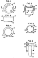
- the modular radial head implant 11 includes a modular head 13 (see, in general, Figs. 1-4) and a modular body 15 (see, in general, Figs. 5 and 6).
- the modular head 13 includes a proximal end 17 having a slight concavity 19 therein for articulation with the capitellum C of a humerus (see Fig. 41).
- the modular head 13 has a distal end 21 and an outer wall 23 extending between the proximal and distal ends 17 , 21 thereof.
- the outer wall 23 of the modular head 13 preferably curves outwardly slightly between said proximal and distal ends 17 , 21 thereof as clearly shown in Figs. 2 and 3 with the modular head 13 forming a circular disc with a barrel-shaped outer wall.
- the modular head 13 thus substantially reproduces the anatomical articular geometry of the head H , or proximal end P , of a radius R .
- the modular head 13 includes a first lock member 25 .
- the first lock member 25 preferably has a cavity 27 with a female taper.
- the sides of the cavity 27 preferably taper inwardly from the distal end 21 of the modular head 13 a combined total of approximately 3 as indicated by the arrow 29 in Fig. 2.
- the modular body 15 includes a distal end 31 for engaging the proximal end P of the radius R (see Figs. 39-41), and a proximal end 33 .
- the modular body 15 includes a second lock member 35 for coacting with the first lock member 25 of the modular head 13 to lock the modular head 13 and the modular body 15 together.
- the distal end 31 of the modular body 15 preferably has a elongated stem 37 for extending into the medullary canal MC of the proximal end P of the radius R (see Figs. 39-41).
- the proximal end 33 of the modular body 15 preferably has an enlarged boss or platform 39 for fitting into the cavity 27 of the first lock member 25 of the modular head 13 .
- the platform 39 preferably has a male taper for coacting with the female taper of the cavity 27 of the first lock member 25 of the modular head 13 to lock the modular head 13 and the modular body 15 together.
- the sides of the platform 39 preferably taper outwardly from the proximal end 33 of the modular body 15 a combined total of approximately 3 as indicated by the arrow 41 in Fig. 6, and the platform 39 is preferably sized so as to tightly fit into the cavity 27 so that the male and female tapers will securely lock together when the modular head 13 and modular body 15 are forcibly brought together as will now be apparent to those skilled in the art.
- the modular body 15 has a drainage passage 43 allowing fluid trapped between the first and second lock members 25 , 33 to drain out.
- the drainage passage 43 preferably consists of a hole or aperture 45 extending through the platform 39 from the proximal end 33 of the modular body 15 , through the platform 39 to a point exterior of the stern 37 as clearly shown in Fig. 6.
- the modular body 15 has a plurality of spaced drainage passages 43 through the platform 39 as shown in Fig. 5.
- the modular head 13 and modular body 15 may be constructed in various manners and out of various materials as will now be apparent to those skilled in the art to substantially reproduce anatomical articular geometry.
- the modular head 13 and modular body 15 can each be machined or otherwise constructed as a one-piece, integral unit out of a medical grade, physiologically acceptable material such as a cobalt chromium molybdenum alloy or the like, in various sizes to fit a range of typical patients, etc.
- the modular head 13 and modular body 15 are preferably highly polished.
- the modular radial head implant 11 includes a plurality of different size modular heads 13 and bodies 15 for allowing different size modular radial head implants 11 to be assembled from individual heads 13 and bodies 15 .
- modular heads 13 may be provided with 5 different head diameters ranging between 20 and 28 millimeters in 2 millimeter increments, and with 3 different head heights ranging between 9 and 13 millimeters in 2 millimeter increments.
- Modular bodies 15 may be provided with 5 different stem diameters ranging between 5.5 and 9.5 millimeters in 1 millimeter increments, and with 3 different stem lengths ranging between 20 and 24 millimeters in 2 millimeter increments.
- the various heads 13 and bodies 15 are preferably universally modular, so that all of the bodies 15 will work with all of the heads 13 , and vice versa.
- the system of the present invention includes a modular radial head sizer 2.11 (see, in general, Figs. 34-38) for allowing a trial reduction of the elbow joint to help determine the proper size modular radial head implant 11 to use as will now be apparent to those skilled in the art.
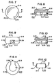
- the modular radial head sizer 2.11 includes a modular head 2.13 (see, in general, Figs. 7-11) and a modular body 2.15 (see, in general, Figs. 12-15).
- the modular head 2.13 includes a proximal end 2.17 having a slight concavity 2.19 therein for articulation with the capitellum C of a humerus (see Fig. 38) during trial reduction of the modular radial head sizer 2.11 .
- the modular head 2.13 has a distal end 2.21 and an outer wall 2.23 extending between the proximal and distal ends 2.17 , 2.21 thereof.
- the outer wall 2.23 of the modular head 2.13 preferably curves outwardly slightly between said proximal and distal ends 2.17 , 2.21 thereof as clearly shown in Figs. 8-10 with the modular head 2.13 forming a circular disc with a barrel-shaped outer wall.
- the modular head 2.13 thus substantially reproduces the anatomical articular geometry of the head H , or proximal end P , of a radius R .
- the modular head 2.13 has a cavity 2.27 for lockably receiving a portion of the modular body 2.15 as will hereinafter become apparent, and has a side entrance opening 2.28 to the cavity 2.27 through the outer wall 2.23 .
- the modular head 2.13 preferably has a internally threaded aperture or cavity 2.29 extending into or through the outer wall 2.23 . As indicated in Figs. 9 and 10, the threaded cavity 2.29 may be directly opposite the side entrance opening 2.28 .
- the modular body 2.15 includes a distal end 2.31 for engaging the proximal end P of the radius R (see, in general, Figs. 31, 32, 34-36 and 38), and a proximal end 2.33 .
- the distal end 2.31 of the modular body 2.15 preferably has a elongated stem 2.37 for extending into the medullary canal MC of the proximal end P of the radius R (see Figs. 31, 32, 34-36 and 38).
- the proximal end 2.33 of the modular body 2.15 preferably has an enlarged boss or platform 2.39 for fitting into the cavity 2.27 of the modular head 2.13 .
- the platform 2.39 is adapted to be inserted through the side entrance opening 2.28 of said modular head 2.13 into the cavity 2.27 of the modular head 2.13 .
- the modular radial head sizer 2.11 preferably includes lock means 2.47 (see, in general, Fig. 37) for locking the modular head 2.13 and modular body 2.15 together after the platform 2.39 of the modular body 2.15 is inserted into the cavity 2.27 of the modular head 2.13 through the side entrance opening 2.28 of the modular head 2.13 .
- the lock means 2.47 preferably includes ball-and-detent type means for locking the modular head 2.13 and modular body 2.15 together when the platform 2.39 of the modular body 2.15 is inserted into the cavity 2.27 of the modular head 2.13 through the side entrance opening 2.28 of the modular head 2.13 and rotated.
- the ball-and-detent type means may be any typical operation and construction now apparent to those skilled in the art such as a true ball-and-detent lock including a ball-and-spring means 2.51 in the opposite ends of the platform 2.39 as clearly shown in Fig. 13, and coacting detents or apertures 2.53 in the modular head 2.13 on opposite sides of the cavity 2.27 as clearly shown in Fig. 8 spaced 90 from the side entrance opening 2.28 so that the modular head 2.13 and modular body 2.15 will be locked together when the platform 2.39 of the modular body 2.15 is inserted into the cavity 2.27 of the modular head 2.13 through the side entrance opening 2.28 of the modular head 2.13 and rotated 90 as will now be apparent to those skilled in the art.
- the proximal end or neck 2.55 of the stem 2.37 immediately adjacent the platform 2.39 of the modular body 2.15 preferably has at least two opposite flats 2.57 on the exterior thereof located parallel to the flat sides of the platform 2.39 for reasons which will hereinafter become apparent.
- the neck 2.55 may have three sets of opposite flats 2.57 to provide a hexagonal cross section as clearly shown in Fig. 15.
- the modular head 2.13 and modular body 2.15 may be constructed in various manners and out of various materials as will now be apparent to those skilled in the art to substantially reproduce anatomical articular geometry.
- the modular head 2.13 and modular body 2.15 except for the ball-and-spring means 2.51 , can each be machined or otherwise constructed as a one-piece, integral unit out of a medical grade, physiologically acceptable material, in various sizes to fit a range of typical patients, etc.
- the modular radial head sizer 2.11 includes a plurality of different size modular heads 2.13 and bodies 2.15 for allowing different size modular radial head sizers 2.11 to be assembled from individual heads 2.13 and bodies 2.15 .
- modular heads 2.13 may be provided to conform to the modular heads 13 of the modular radial head implants 11 with 5 different head diameters ranging between 20 and 28 millimeters in 2 millimeter increments, and with 3 different head heights ranging between 9 and 13 millimeters in 2 millimeter increments.
- modular bodies 2.15 may be provided to conform to the modular bodies 15 of the modular radial head implants 11 with 5 different stem diameters ranging between 5.5 and 9.5 millimeters in 1 millimeter increments, and with 3 different stem lengths ranging between 20 and 24 millimeters in 2 millimeter increments.
- the various heads 2.13 and bodies 2.15 are preferably universally modular, so that all of the bodies 2.15 will work with all of the heads 2.13 , and vice versa.
- the system of the present invention includes modular radial head sizer insertion instrumentation for use in inserting the modular radial head sizer 2.11 into the elbow joint.
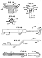
- the instrumentation including a modular sizer head insertion tool 3.13 and a modular sizer body holding tool 3.15 (see, in general, Figs. 16-18).
- the modular sizer head insertion tool 3.13 includes an elongated body 3.17 having a first end 3.19 and a second end 3.21 .
- the first end 3.19 of the elongated body 3.17 of the modular sizer head insertion tool 3.13 includes a grip portion 3.23 .
- the second end 3.21 of the elongated body 3.17 of the modular sizer head insertion tool 3.13 includes a threaded stud 3.25 for screwing into the threaded cavity 2.29 in the outer wall 2.23 of the modular head 2.13 of the modular radial head sizer 2.11 .
- the modular sizer body holding tool 3.15 includes an elongated body 3.27 having a first end 3.29 and a second end 3.31 .
- the first end 3.29 of the elongated body 3.27 of the modular sizer body holding tool 3.15 includes a grip portion 3.33 .
- the second end 3.31 of the elongated body 3.27 of the modular sizer body holding tool 3.15 has a mouth 3.35 with two opposite and parallel jaws 3.37 for engaging the flats 2.57 of the neck portion 2.55 of the stem 2.37 of the modular body 2.15 of the modular radial head sizer 2.11 to allow the modular sizer body holding tool 3.15 to hold the modular body 2.15 of the modular radial head sizer 2.11 against rotation.
- the elongated body 3.27 preferably has a double bend 3.39 between the first and second ends 3.29 , 3.31 as clearly shown in Fig. 17 to provide enhanced finger clearance adjacent the grip portion 3.33 as will hereinafter become apparent.
- the modular sizer head insertion tool 3.13 and modular sizer body holding tool 3.15 may be constructed in various manners and out of various materials as will now be apparent to those skilled in the art.
- the modular sizer head insertion tool 3.13 and modular sizer body holding tool 3.15 can each be machined or otherwise constructed as a one-piece, integral unit out of a medical grade or the like in various sizes to fit the respective modular head 2.13 and modular body 2.15 of the modular radial head sizer 2.11 .
- the system of the present invention includes a modular radial head broach 4.11 (see, in general, Figs. 19-21) for use in preparing the medullary canal MC of the proximal end P of the radius R to receive the proper size modular radial head implant 11 .
- the modular radial head broach 4.11 includes an elongated body 4.13 having a first end 4.15 and a second end 4.17 .
- the first end 4.15 of the elongated body 4.13 includes a grip portion 4.19 , either formed as a part thereof or attached thereto, and especially formed to be hand-gripped.
- the second end 4.17 of the elongated body 4.13 includes a cutting head 4.21 for shaping and enlarging the proximal end of the medullary canal MC .
- the elongated body 4.13 is preferably bent adjacent the cutting head 4.21 as indicated by the arrow 4.23 in Fig. 20, and the cutting head 4.21 is relatively short (shorter than the corresponding implant stem) to allow easy joint access and facilitate introduction into the medullary canal MC .
- the cutting head 4.21 preferably has a blunt, rounded tip 4.25 to protect the capitellum cartilage and prevent soft tissue disruption upon introduction to the joint space.
- Gentle cutting teeth 4.27 are formed on the sides of the cutting head 4.21 from longitudinal flats cut on the circumference of the cutting head 4.21 , spaced every 30
- the modular radial head broach 4.11 may be constructed in various manners and out of various materials as will now be apparent to those skilled in the art.
- the elongated body 4.13 and cutting head 4.21 can be machined or otherwise constructed as a one-piece, integral unit out of a stainless steel or the like, in various sizes to fit a range of typical patients, etc.
- the grip portion 4.19 may be machined or otherwise constructed as a separate unit out of Radel polymer or the like and press fitted or otherwise joined to the first end 4.15 of the elongated body 4.13 .
- the system of the present invention includes a series of modular radial head broaches 4.11 having different size cutting heads 4.21 for allowing the medullary canal MC to be prepared with different internal diameters to receive different size stems 37 of different size modular bodies 15 , etc.
- modular radial head broaches 4.11 may be provided to conform to the modular bodies 15 of the modular radial head implants 11 with 5 different stem diameters ranging between 5.5 and 9.5 millimeters in 1 millimeter increments.
- the system of the present invention includes modular radial head radius crank planer 5.11 for use in preparing the proximal end P of the radius R to receive the modular radial head implant 11 .
- the modular radial head radius crank planer 5.11 provides a "bit and brace" style hand-powered instrument to provide central axis loading with off-axis, bi-directional rotation to provide planing action for the resected end of the radius R .
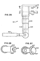
- the modular radial head radius crank planer 5.11 includes an elongated shaft 5.13 having a,first end 5.15 and a second end 5.17 , a handle or knob 5.19 for mounting to the first end 5.15 of the shaft 5.13 , a cutting head 5.21 for mounting to the second end 5.17 of the shaft 5.13 , and a grip member 5.23 for mounting to the shaft 5.13 between the first and second ends 5.15 , 5.17 thereof (see, in general, Fig. 22).
- the cutting head 5.21 has an elongated arm 5.25 terminating in a cutting or planer portion 5.27 .
- the cutting or planer portion 5.27 is in the form of a flat disk with a plurality of cutting teeth 5.29 on one side and a center slot 5.31 for mating with the neck portion 2.55 of the stem 2.37 of the modular body 2.15 of a modular radial head sizer 2.11 .
- the direction of the cutting teeth 5.29 preferably changes 30 every 60 .
- the profile of the cutting teeth 5.29 is preferably created from 1/16 inch (0.15875 centimeter) diameter ball ended slots spaced 0.070 inch (0.1778 centimeter) along the face of the cutting or planer portion 5.27 .
- the shaft 5.13 is off-set as indicated by the arrow 5.33 in Fig. 22 so that a longitudinal axis 5.35 passing through the handle or knob 5.19 will pass through the center of the cutting or planer portion 5.27 as clearly indicated in Fig. 22.
- the modular radial head crank planer 5.11 may be constructed in various manners and out of various materials as will now be apparent to those skilled in the art.
- the elongated shaft 5.13 , handle 5.19 and cutting head 5.21 can be machined or otherwise constructed out of a stainless steel or the like, in various sizes to fit a range of typical patients, etc.
- the grip member 5.23 may be machined or otherwise constructed as a separate unit out of Radel polymer or the like and rotatably positioned on the shaft 5.13 .
- the cutting head 5.21 is preferably modular for replacement due to wear, etc.
- the system of the present invention includes a modular radial head locking instrument 6.11 for use in locking a selected modular head 2.13 and a selected modular body 2.15 of the modular radial head implant 11 .
- the modular radial head locking instrument 6.11 preferably includes an adapted femoral head extractor instrument 6.13 or the like such as the femoral head extractor instrument (No. 5014) manufactured and/or sold by Immedica, Inc. of 871 Mountain Avenue, Springfield, NJ 07081.
- the locking instrument includes a first jaw 6.15 , a second jaw 6.17 , an elongated body 6.19 , and a lever arm 6.21 or the like adapted to cause the first and second jaws 6.15 , 6.17 to move toward one another (see, in general, Fig. 25).
- the first jaw 6.15 is adapted to engage the underside of the platform 39 of a modular body 15 of the modular radial head implant 11
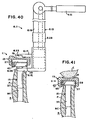
- the second jaw 6.17 is adapted to engage the proximal end 17 of a modular head 13 of the modular radial head implant 11 as clearly shown in Fig 40.
- a soft pad 6.23 manufactured out of plastic or the like is preferably provided on the jaw 6.17 to provide a soft interface with the proximal end 17 of the modular head 13 of the implant 11 to prevent implant damage.
- the first jaw 6.15 preferably has a distal end with a slot 6.25 therein for receiving a portion of the proximal end P of the radius R and/or the stem 37 of the modular body 15 of the modular implant 11 .
- a portion of the first jaw 6.15 adjacent the slot 6.25 preferably forms a raised lip 6.26 for engaging the underside of the platform 39 of a modular body 15 of the modular radial head implant 11 .
- the second jaw 6.17 preferably has a distal end with a modular centering means for receiving and positioning the modular head 15 of the modular implant 11 .
- the modular centering means preferably consist of a curved wall 6.27 on the pad 6.23 to engage and position the proximal end 17 of the modular head 15 of the modular implant 11 .
- the locking instrument 6.11 thus allows offset axial compression of the modular head 13 and modular body 15 of the implant 11 .
- the instrument 6.13 may include the typical screw adjustment and force gauge mechanism 6.29 .
- the modular radial head locking instrument 6.11 may be constructed in various manners and out of various materials as will now be apparent to those skilled in the art.
- the working mechanism of the locking instrument 6.11 preferably consist of an adapted Immedica femoral head extractor.
- the first and second jaws 6.15 , 6.17 can be machined or otherwise constructed out of a stainless steel or the like.
- Several different size pads 6.23 i. e., pads 6.23 with different size curved walls 6.27 to correspond to modular heads 15 having different diameters
- pads 6.23 may be machined or otherwise constructed as separate units out of Ultem polymer or the like corresponding to the different implant sizes, etc.
- the surgical procedure or technique for using the modular radial head system of the present invention can vary as will now be apparent to those skilled in the art.
- the preferred surgical technique preferably includes the following steps:
- the preferred embodiment of the present invention provides:
Abstract
Description
Claims (12)
- A modular implant for replacing the head of the proximal end of a radius and for articulating with the capitellum of a humerus, said implant comprising:(a) a modular head including a proximal end having a concavity therein for articulating with the capitellum of the humerus, and including a first lock member; and(b) a modular body including distal end for connecting to the radius, including a second lock member for coacting with said first lock member of said modular head to lock said modular head and said modular body together, and having a drainage passage allowing fluid trapped between said first and second lock members to drain out.
- The implant of claim 1 in which said first lock member has a cavity with a female taper; and in which second lock member has a platform with a male taper for coacting with said female taper of said cavity of said first lock member of said modular head to lock said modular head and said modular body together.
- The implant of claim 1 in which said modular head forms a circular disc; in which said modular head has a distal end; in which said modular head has an outer wall extending between said proximal and distal ends thereof; and in which said outer wall of said modular head curves outwardly between said proximal and distal ends thereof.
- The implant of claim 1 in which said modular head reproduces the anatomical articular geometry of the proximal end of a radius.
- A modular sizer for trial reduction of the proximal end of a radius, said modular sizer comprising:(a) a modular head including a proximal end, a distal end, and an outer wall extending between said proximal and distal ends thereof; said proximal end of said modular head having a concavity therein for articulating with the capitellum of the humerus; said modular head having a cavity and having a side entrance opening to said cavity through said outer wall; and(b) a modular body including a proximal end and a distal end; said distal end of said modular body including a stem for connecting to the radius; said proximal end of said modular body including a platform adapted to be inserted through said side entrance opening of said modular head into said cavity of said modular head.
- The modular sizer of claim 5 in which is included lock means for locking said modular head and said modular body together after said platform of said modular body is inserted into said cavity of said modular head through said side entrance opening of said modular head.
- The modular sizer of claim 6 in which said lock means includes ball-and-detent means for locking said modular head and said modular body together when said platform of said modular body is inserted into said cavity of said modular head through said side entrance opening of said modular head and rotated.
- A modular radial head system comprising:(a) a modular radial head sizer for trial reduction of the proximal end of a radius, said modular radial head sizer including a modular head and a modular body;said modular head of said modular radial head sizer including a proximal end, a distal end, and an outer wall extending between said proximal and distal ends thereof; said proximal end of said modular head having a concavity therein for articulating with the capitellum of the humerus; said modular head having a cavity in said distal end for receiving a portion of said modular body and having a threaded cavity in said outer wall;said modular body of said modular radial head sizer including a proximal end for inserting into said cavity in said distal end of said modular head and a distal end for connecting to the radius; said modular body of said modular radial head sizer having at least two opposite flats on the exterior thereof; and(b) modular radial head sizer insertion instrumentation for use in inserting said modular sizer; said instrumentation including a modular sizer head insertion tool and a modular sizer body holding tool;said modular sizer head insertion tool including an elongated body having a first end and a second end; said first end of said elongated body of said modular sizer head insertion tool including a grip portion; said second end of said elongated body of said modular sizer head insertion tool including a threaded stud for screwing into said threaded cavity in said outer wall of said modular head;said modular sizer body holding tool including an elongated body having a first end and a second end; said first end of said elongated body of said modular sizer body holding tool including a grip portion; said second end of said elongated body of said modular sizer body holding tool having a mouth with two opposite and parallel jaws for engaging said flats of said modular body of said modular radial head sizer to allow said modular sizer body holding tool to hold said modular body of said modular radial head sizer against rotation.
- The modular radial head system of claim 8 in which said elongated body of said modular sizer body holding tool has a double bend between said first and second ends thereof to provide clearance between said grip portion and said mouth thereof.
- A modular broach for preparing the medullary canal of the proximal end of a radius for receiving the stem of a modular radial head implant; said modular broach comprising:(a) an elongated body having a first end and a second end;(b) a grip portion on said first end of said elongated body; and(c) a cutting head on said second end of said elongated body for shaping and enlarging the proximal end of the medullary canal; said cutting head having a blunt, rounded tip to protect the capitellum cartilage and prevent soft tissue disruption upon introduction to the joint space.
- The modular broach of claim 10 in which said elongated body is bent adjacent the cutting head to allow easy joint access and facilitate introduction into the medullary canal.
- A modular radial head system comprising:(a) a modular radial head sizer for trial reduction of the proximal end of a radius, said modular radial head sizer including a stem for inserting into the medullary canal of the radius; said stem having a neck portion with at least two opposite flats on the exterior thereof; and(b) a modular radial head radius crank planer for use in preparing the proximal end of the radius to receive a radial head implant; said modular radial head radius crank planer including a cutting head having a cutting portion with a center slot for mating with said neck portion of said stem of said modular radial head sizer.13. The system of claim 12 in which said cutting portion of said cutting head of said modular radial head radius crank planer has a plurality of elongated cutting teeth on one side thereof, the direction of said cutting teeth changing 30 every 60 .14. A modular radial head system comprising:(a) a modular implant for replacing the head of the proximal end of a radius and for articulating with the capitellum of a humerus; said implant including a modular head having a first lock member, and including an modular stem having a second lock member for coacting with said first lock member of said modular head to lock said modular head and said modular stem together; and(b) a modular radial head locking instrument said modular head and said modular stem of said modular implant to one another; said modular radial head locking instrument including a first jaw, a second jaw, and a control mechanism for urging said first and second jaws together; said first jaw having a distal end adapted to engage a portion of said modular stem and having a proximal end; said second jaw having a distal end adapted to engage a portion of said modular head and having a proximal end; said control mechanism engaging said proximal ends of said first and second jaws to provide offset axial compression of said modular head and said modular stem.15. The system of claim 14 in which said distal end of said first jaw of said modular radial head locking instrument has a slot for receiving a portion of said modular stem; and in which said distal end of said second jaw of said modular radial head locking instrument has a centering means for receiving and positioning said modular head.
Priority Applications (2)
| Application Number | Priority Date | Filing Date | Title |
|---|---|---|---|
| EP09150427A EP2078511B1 (en) | 1999-09-01 | 2000-08-03 | Modular head system for replacing the head of the proximal end of a radius |
| EP06118224A EP1772118B1 (en) | 1999-09-01 | 2000-08-03 | Modular head system for replacing the head of the proximal end of a radius |
Applications Claiming Priority (2)
| Application Number | Priority Date | Filing Date | Title |
|---|---|---|---|
| US388093 | 1989-08-01 | ||
| US09/388,093 US6270529B1 (en) | 1999-09-01 | 1999-09-01 | Modular implant for replacing end of radius and having drainage passage for trapped fluid |
Related Child Applications (1)
| Application Number | Title | Priority Date | Filing Date |
|---|---|---|---|
| EP06118224A Division EP1772118B1 (en) | 1999-09-01 | 2000-08-03 | Modular head system for replacing the head of the proximal end of a radius |
Publications (3)
| Publication Number | Publication Date |
|---|---|
| EP1080701A2 true EP1080701A2 (en) | 2001-03-07 |
| EP1080701A3 EP1080701A3 (en) | 2001-07-18 |
| EP1080701B1 EP1080701B1 (en) | 2006-08-02 |
Family
ID=23532659
Family Applications (3)
| Application Number | Title | Priority Date | Filing Date |
|---|---|---|---|
| EP00250260A Expired - Lifetime EP1080701B1 (en) | 1999-09-01 | 2000-08-03 | Radial head implant |
| EP06118224A Expired - Lifetime EP1772118B1 (en) | 1999-09-01 | 2000-08-03 | Modular head system for replacing the head of the proximal end of a radius |
| EP09150427A Expired - Lifetime EP2078511B1 (en) | 1999-09-01 | 2000-08-03 | Modular head system for replacing the head of the proximal end of a radius |
Family Applications After (2)
| Application Number | Title | Priority Date | Filing Date |
|---|---|---|---|
| EP06118224A Expired - Lifetime EP1772118B1 (en) | 1999-09-01 | 2000-08-03 | Modular head system for replacing the head of the proximal end of a radius |
| EP09150427A Expired - Lifetime EP2078511B1 (en) | 1999-09-01 | 2000-08-03 | Modular head system for replacing the head of the proximal end of a radius |
Country Status (4)
| Country | Link |
|---|---|
| US (2) | US6270529B1 (en) |
| EP (3) | EP1080701B1 (en) |
| CA (1) | CA2314863C (en) |
| DE (3) | DE60029702T2 (en) |
Cited By (14)
| Publication number | Priority date | Publication date | Assignee | Title |
|---|---|---|---|---|
| EP1365165A1 (en) * | 2002-05-22 | 2003-11-26 | Bioprofile | Conical coupling and prosthesis comprising such a coupling |
| EP1905396A1 (en) * | 2006-09-29 | 2008-04-02 | DePuy Products, Inc. | Assembly tool for modular orthopaedic implants |
| US8419799B2 (en) | 2003-06-25 | 2013-04-16 | Depuy Products, Inc. | Assembly tool for modular implants and associated method |
| US8518050B2 (en) | 2007-10-31 | 2013-08-27 | DePuy Synthes Products, LLC | Modular taper assembly device |
| US9095452B2 (en) | 2010-09-01 | 2015-08-04 | DePuy Synthes Products, Inc. | Disassembly tool |
| US9101495B2 (en) | 2010-06-15 | 2015-08-11 | DePuy Synthes Products, Inc. | Spiral assembly tool |
| WO2016113539A1 (en) * | 2015-01-15 | 2016-07-21 | Depuy (Ireland) | Assembly tool |
| US9717545B2 (en) | 2007-10-30 | 2017-08-01 | DePuy Synthes Products, Inc. | Taper disengagement tool |
| US9901452B2 (en) | 2013-03-14 | 2018-02-27 | Imds Corporation | Radial head implant |
| US9937048B2 (en) | 2015-01-15 | 2018-04-10 | Depuy Ireland Unlimited Company | Femoral stem including an anchor to facilitate assembly and implantation |
| US10064725B2 (en) | 2011-04-06 | 2018-09-04 | DePuy Synthes Products, Inc. | Distal reamer for use during an orthopaedic surgical procedure to implant a revision hip prosthesis |
| US10357372B2 (en) | 2013-03-28 | 2019-07-23 | Mayo Foundation For Medical Education And Research | Radial head trials |
| US11207197B2 (en) | 2019-08-01 | 2021-12-28 | DePuy Synthes Products, Inc. | Orthopaedic surgical instrument for total hip arthroplasty and associated orthopaedic surgical method of use |
| US20220296389A1 (en) * | 2019-05-14 | 2022-09-22 | Loci Orthopaedics | Set of tools for installing an implant |
Families Citing this family (115)
| Publication number | Priority date | Publication date | Assignee | Title |
|---|---|---|---|---|
| US6027534A (en) * | 1997-11-03 | 2000-02-22 | Deputy Orthopaedics, Inc. | Modular elbow |
| US6270529B1 (en) * | 1999-09-01 | 2001-08-07 | Wright Medical Technology, Inc. | Modular implant for replacing end of radius and having drainage passage for trapped fluid |
| US8920509B2 (en) | 2000-04-10 | 2014-12-30 | Biomet Manufacturing, Llc | Modular radial head prosthesis |
| US8114163B2 (en) | 2000-04-10 | 2012-02-14 | Biomet Manufacturing Corp. | Method and apparatus for adjusting height and angle for a radial head |
| US8535382B2 (en) | 2000-04-10 | 2013-09-17 | Biomet Manufacturing, Llc | Modular radial head prostheses |
| US6709459B1 (en) * | 2000-08-31 | 2004-03-23 | Mayo Foundation For Medical Education And Research | Radial implant system |
| US9155626B2 (en) | 2012-09-10 | 2015-10-13 | Acumed Llc | Radial head prosthesis with floating articular member |
| US7255716B2 (en) * | 2002-05-09 | 2007-08-14 | Pubols Steven C | Method and instruments for inserting modular implant components |
| US7273499B2 (en) * | 2002-09-30 | 2007-09-25 | Depuy Products, Inc. | Modular trial mechanism |
| US7854737B2 (en) * | 2002-12-20 | 2010-12-21 | Depuy Products, Inc. | Instrument and associated method of trailing for modular hip stems |
| US7022141B2 (en) * | 2002-12-20 | 2006-04-04 | Depuy Products, Inc. | Alignment device for modular implants and method |
| US7235106B2 (en) * | 2002-12-20 | 2007-06-26 | Depuy Products, Inc. | Modular hip stems and associated method of trialing |
| US7452381B2 (en) * | 2003-01-30 | 2008-11-18 | Mayo Foundation For Medical Education And Research | Radial head replacement system |
| US7582092B2 (en) | 2003-06-25 | 2009-09-01 | Depuy Products, Inc. | Assembly tool for modular implants and associated method |
| US20040267267A1 (en) * | 2003-06-25 | 2004-12-30 | Daniels David Wayne | Non-linear reamer for bone preparation and associated method |
| US7074224B2 (en) * | 2003-06-25 | 2006-07-11 | Depuy Products, Inc. | Modular tapered reamer for bone preparation and associated method |
| US20050049710A1 (en) * | 2003-08-28 | 2005-03-03 | O'driscoll Shawn W. | Prosthesis for partial replacement of an articulating surface on bone |
| US7815644B2 (en) * | 2003-12-19 | 2010-10-19 | Masini Michael A | Instrumentation and methods for refining image-guided and navigation-based surgical procedures |
| US7785328B2 (en) * | 2003-12-30 | 2010-08-31 | Depuy Products, Inc. | Minimally invasive bone miller apparatus |
| EP1732476B1 (en) * | 2004-03-11 | 2017-02-01 | Acumed LLC | Systems for bone replacement |
| US7740661B2 (en) * | 2004-08-23 | 2010-06-22 | Integra Lifesciences Corporation | Radial head implant apparatuses and methods |
| US8353965B2 (en) * | 2004-09-03 | 2013-01-15 | Seitz Jr William H | Small joint orthopedic implants and their manufacture |
| DE602005014716D1 (en) * | 2004-09-08 | 2009-07-16 | Arthrex Inc | Modular joint endoprosthesis |
| US7160329B2 (en) * | 2004-12-01 | 2007-01-09 | Mayo Foundation For Medical Research And Education | Radial-capitellar implant |
| US7458989B2 (en) * | 2005-06-30 | 2008-12-02 | University Of Florida Rearch Foundation, Inc. | Intraoperative joint force measuring device, system and method |
| DE602005016791D1 (en) * | 2005-07-08 | 2009-11-05 | Biedermann Motech Gmbh | Bone anchoring device |
| US7819924B2 (en) * | 2005-11-14 | 2010-10-26 | Ascension Orthopedics, Inc. | Distal radioulnar joint prosthesis |
| US9289253B2 (en) | 2006-02-27 | 2016-03-22 | Biomet Manufacturing, Llc | Patient-specific shoulder guide |
| US8591516B2 (en) | 2006-02-27 | 2013-11-26 | Biomet Manufacturing, Llc | Patient-specific orthopedic instruments |
| US20150335438A1 (en) | 2006-02-27 | 2015-11-26 | Biomet Manufacturing, Llc. | Patient-specific augments |
| US8092465B2 (en) | 2006-06-09 | 2012-01-10 | Biomet Manufacturing Corp. | Patient specific knee alignment guide and associated method |
| US8608748B2 (en) | 2006-02-27 | 2013-12-17 | Biomet Manufacturing, Llc | Patient specific guides |
| US9173661B2 (en) | 2006-02-27 | 2015-11-03 | Biomet Manufacturing, Llc | Patient specific alignment guide with cutting surface and laser indicator |
| US8864769B2 (en) | 2006-02-27 | 2014-10-21 | Biomet Manufacturing, Llc | Alignment guides with patient-specific anchoring elements |
| US8377066B2 (en) | 2006-02-27 | 2013-02-19 | Biomet Manufacturing Corp. | Patient-specific elbow guides and associated methods |
| US9345548B2 (en) | 2006-02-27 | 2016-05-24 | Biomet Manufacturing, Llc | Patient-specific pre-operative planning |
| US8535387B2 (en) | 2006-02-27 | 2013-09-17 | Biomet Manufacturing, Llc | Patient-specific tools and implants |
| US9918740B2 (en) | 2006-02-27 | 2018-03-20 | Biomet Manufacturing, Llc | Backup surgical instrument system and method |
| US9907659B2 (en) | 2007-04-17 | 2018-03-06 | Biomet Manufacturing, Llc | Method and apparatus for manufacturing an implant |
| US7967868B2 (en) | 2007-04-17 | 2011-06-28 | Biomet Manufacturing Corp. | Patient-modified implant and associated method |
| US8858561B2 (en) | 2006-06-09 | 2014-10-14 | Blomet Manufacturing, LLC | Patient-specific alignment guide |
| US8241293B2 (en) | 2006-02-27 | 2012-08-14 | Biomet Manufacturing Corp. | Patient specific high tibia osteotomy |
| US9113971B2 (en) | 2006-02-27 | 2015-08-25 | Biomet Manufacturing, Llc | Femoral acetabular impingement guide |
| US8133234B2 (en) | 2006-02-27 | 2012-03-13 | Biomet Manufacturing Corp. | Patient specific acetabular guide and method |
| US8568487B2 (en) | 2006-02-27 | 2013-10-29 | Biomet Manufacturing, Llc | Patient-specific hip joint devices |
| US10278711B2 (en) | 2006-02-27 | 2019-05-07 | Biomet Manufacturing, Llc | Patient-specific femoral guide |
| US8407067B2 (en) | 2007-04-17 | 2013-03-26 | Biomet Manufacturing Corp. | Method and apparatus for manufacturing an implant |
| US8603180B2 (en) | 2006-02-27 | 2013-12-10 | Biomet Manufacturing, Llc | Patient-specific acetabular alignment guides |
| US8608749B2 (en) | 2006-02-27 | 2013-12-17 | Biomet Manufacturing, Llc | Patient-specific acetabular guides and associated instruments |
| US9339278B2 (en) | 2006-02-27 | 2016-05-17 | Biomet Manufacturing, Llc | Patient-specific acetabular guides and associated instruments |
| US9795399B2 (en) | 2006-06-09 | 2017-10-24 | Biomet Manufacturing, Llc | Patient-specific knee alignment guide and associated method |
| US8597298B2 (en) | 2006-09-29 | 2013-12-03 | DePuy Synthes Products, LLC | Proximal reamer |
| GB2442441B (en) | 2006-10-03 | 2011-11-09 | Biomet Uk Ltd | Surgical instrument |
| WO2008098250A2 (en) * | 2007-02-10 | 2008-08-14 | Small Bone Innovations, Inc. | Radial head implant and related instrument |
| US20090112219A1 (en) * | 2007-10-31 | 2009-04-30 | Daniels David W | Taper sleeve extractor |
| US8167882B2 (en) * | 2008-09-30 | 2012-05-01 | Depuy Products, Inc. | Minimally invasive bone miller apparatus |
| US9247967B2 (en) * | 2008-12-03 | 2016-02-02 | Warsaw Orthopedic, Inc. | Rod and anchor system and method for using |
| US20100234846A1 (en) * | 2009-03-13 | 2010-09-16 | Eglseder W Andrew | Intramedullary radial head locking pin implant |
| JP5674785B2 (en) * | 2009-08-06 | 2015-02-25 | スケルタル ダイナミクス エルエルシー | Alignable prosthetic device, system, and method |
| DE102009028503B4 (en) | 2009-08-13 | 2013-11-14 | Biomet Manufacturing Corp. | Resection template for the resection of bones, method for producing such a resection template and operation set for performing knee joint surgery |
| US8968411B2 (en) * | 2009-12-17 | 2015-03-03 | Zimmer, Inc. | Modular elbow prosthesis |
| US8632547B2 (en) | 2010-02-26 | 2014-01-21 | Biomet Sports Medicine, Llc | Patient-specific osteotomy devices and methods |
| US9271744B2 (en) | 2010-09-29 | 2016-03-01 | Biomet Manufacturing, Llc | Patient-specific guide for partial acetabular socket replacement |
| US9968376B2 (en) | 2010-11-29 | 2018-05-15 | Biomet Manufacturing, Llc | Patient-specific orthopedic instruments |
| US9241745B2 (en) | 2011-03-07 | 2016-01-26 | Biomet Manufacturing, Llc | Patient-specific femoral version guide |
| US8715289B2 (en) | 2011-04-15 | 2014-05-06 | Biomet Manufacturing, Llc | Patient-specific numerically controlled instrument |
| US8956364B2 (en) | 2011-04-29 | 2015-02-17 | Biomet Manufacturing, Llc | Patient-specific partial knee guides and other instruments |
| US8668700B2 (en) | 2011-04-29 | 2014-03-11 | Biomet Manufacturing, Llc | Patient-specific convertible guides |
| US8532807B2 (en) | 2011-06-06 | 2013-09-10 | Biomet Manufacturing, Llc | Pre-operative planning and manufacturing method for orthopedic procedure |
| US9084618B2 (en) | 2011-06-13 | 2015-07-21 | Biomet Manufacturing, Llc | Drill guides for confirming alignment of patient-specific alignment guides |
| US20130001121A1 (en) | 2011-07-01 | 2013-01-03 | Biomet Manufacturing Corp. | Backup kit for a patient-specific arthroplasty kit assembly |
| US8764760B2 (en) | 2011-07-01 | 2014-07-01 | Biomet Manufacturing, Llc | Patient-specific bone-cutting guidance instruments and methods |
| US8597365B2 (en) | 2011-08-04 | 2013-12-03 | Biomet Manufacturing, Llc | Patient-specific pelvic implants for acetabular reconstruction |
| US9066734B2 (en) | 2011-08-31 | 2015-06-30 | Biomet Manufacturing, Llc | Patient-specific sacroiliac guides and associated methods |
| US9295497B2 (en) | 2011-08-31 | 2016-03-29 | Biomet Manufacturing, Llc | Patient-specific sacroiliac and pedicle guides |
| US9386993B2 (en) | 2011-09-29 | 2016-07-12 | Biomet Manufacturing, Llc | Patient-specific femoroacetabular impingement instruments and methods |
| KR20130046336A (en) | 2011-10-27 | 2013-05-07 | 삼성전자주식회사 | Multi-view device of display apparatus and contol method thereof, and display system |
| US9301812B2 (en) | 2011-10-27 | 2016-04-05 | Biomet Manufacturing, Llc | Methods for patient-specific shoulder arthroplasty |
| US9451973B2 (en) | 2011-10-27 | 2016-09-27 | Biomet Manufacturing, Llc | Patient specific glenoid guide |
| US9554910B2 (en) | 2011-10-27 | 2017-01-31 | Biomet Manufacturing, Llc | Patient-specific glenoid guide and implants |
| ES2635542T3 (en) | 2011-10-27 | 2017-10-04 | Biomet Manufacturing, Llc | Glenoid guides specific to the patient |
| US8696623B2 (en) * | 2011-11-16 | 2014-04-15 | Mgs Mfg. Group, Inc. | Injection molded adjustable shape abscess irrigation device |
| US9237950B2 (en) | 2012-02-02 | 2016-01-19 | Biomet Manufacturing, Llc | Implant with patient-specific porous structure |
| US8936647B2 (en) | 2012-06-22 | 2015-01-20 | Zimmer, Inc. | Elbow prosthesis |
| US10201374B2 (en) | 2012-06-22 | 2019-02-12 | Zimmer, Inc. | Assembly tool for a prosthesis |
| US9510956B2 (en) * | 2012-11-06 | 2016-12-06 | Biomet Manufacturing, Llc | Prosthetic system |
| US9204977B2 (en) | 2012-12-11 | 2015-12-08 | Biomet Manufacturing, Llc | Patient-specific acetabular guide for anterior approach |
| US9060788B2 (en) | 2012-12-11 | 2015-06-23 | Biomet Manufacturing, Llc | Patient-specific acetabular guide for anterior approach |
| US9839438B2 (en) | 2013-03-11 | 2017-12-12 | Biomet Manufacturing, Llc | Patient-specific glenoid guide with a reusable guide holder |
| US9579107B2 (en) | 2013-03-12 | 2017-02-28 | Biomet Manufacturing, Llc | Multi-point fit for patient specific guide |
| US9498233B2 (en) | 2013-03-13 | 2016-11-22 | Biomet Manufacturing, Llc. | Universal acetabular guide and associated hardware |
| US9826981B2 (en) | 2013-03-13 | 2017-11-28 | Biomet Manufacturing, Llc | Tangential fit of patient-specific guides |
| US9517145B2 (en) | 2013-03-15 | 2016-12-13 | Biomet Manufacturing, Llc | Guide alignment system and method |
| US20150112349A1 (en) | 2013-10-21 | 2015-04-23 | Biomet Manufacturing, Llc | Ligament Guide Registration |
| WO2015081311A1 (en) * | 2013-11-26 | 2015-06-04 | Nexus Spine, L.L.C. | Surgical tool for a pedicle screw |
| US10478313B1 (en) | 2014-01-10 | 2019-11-19 | Nuvasive, Inc. | Spinal fusion implant and related methods |
| US10282488B2 (en) | 2014-04-25 | 2019-05-07 | Biomet Manufacturing, Llc | HTO guide with optional guided ACL/PCL tunnels |
| US9408616B2 (en) | 2014-05-12 | 2016-08-09 | Biomet Manufacturing, Llc | Humeral cut guide |
| US9561040B2 (en) | 2014-06-03 | 2017-02-07 | Biomet Manufacturing, Llc | Patient-specific glenoid depth control |
| US9839436B2 (en) | 2014-06-03 | 2017-12-12 | Biomet Manufacturing, Llc | Patient-specific glenoid depth control |
| US9833245B2 (en) | 2014-09-29 | 2017-12-05 | Biomet Sports Medicine, Llc | Tibial tubercule osteotomy |
| US9826994B2 (en) | 2014-09-29 | 2017-11-28 | Biomet Manufacturing, Llc | Adjustable glenoid pin insertion guide |
| US10632001B2 (en) * | 2014-12-17 | 2020-04-28 | Integra Lifesciences Corporation | Orthopedic implant sizing instruments, systems, and methods |
| US9820868B2 (en) | 2015-03-30 | 2017-11-21 | Biomet Manufacturing, Llc | Method and apparatus for a pin apparatus |
| US10226262B2 (en) | 2015-06-25 | 2019-03-12 | Biomet Manufacturing, Llc | Patient-specific humeral guide designs |
| US10568647B2 (en) | 2015-06-25 | 2020-02-25 | Biomet Manufacturing, Llc | Patient-specific humeral guide designs |
| US9763792B2 (en) * | 2015-10-01 | 2017-09-19 | Acumed Llc | Radial head prosthesis with rotate-to-lock interface |
| US10722310B2 (en) | 2017-03-13 | 2020-07-28 | Zimmer Biomet CMF and Thoracic, LLC | Virtual surgery planning system and method |
| EP3606475B1 (en) | 2017-04-04 | 2021-01-27 | Tornier, Inc. | Elbow joint prostheses |
| DE102017126618A1 (en) * | 2017-11-13 | 2019-05-16 | Ot Medizintechnik Gmbh | Radial head implant |
| CN108143521B (en) * | 2017-12-12 | 2019-11-12 | 常州大学 | A kind of apery humeroradial joint in elbow joint |
| RU184582U1 (en) * | 2018-04-11 | 2018-10-31 | Общество с ограниченной ответственностью "Мойе Керамик-Имплантате" | PROSTHESIS OF THE PROXIMAL BEAM HEAD |
| JP7013620B2 (en) | 2018-10-03 | 2022-01-31 | ハウメディカ オステオニクス コーポレイション | Elbow prosthesis |
| US20210290401A1 (en) * | 2020-03-18 | 2021-09-23 | In2Bones Usa, Llc | Radial head fracture treatment system |
| US11850158B2 (en) * | 2020-05-26 | 2023-12-26 | Howmedica Osteonics Corp. | Orthopedic surgical implant device with porous material and fluid channels for cleaning the porous material |
Family Cites Families (22)
| Publication number | Priority date | Publication date | Assignee | Title |
|---|---|---|---|---|
| US460155A (en) * | 1891-09-29 | Wrench | ||
| GB1320956A (en) * | 1970-10-09 | 1973-06-20 | St Peters Research Ltd | Prosthetic joints |
| GB1601576A (en) | 1977-06-01 | 1981-10-28 | Howmedica | Elbow prosthesis |
| GB2022422B (en) * | 1978-05-31 | 1983-01-12 | Wadsworth T G | Elbow replacement prosthesis |
| US4457306A (en) * | 1982-05-05 | 1984-07-03 | Howmedica, Inc. | Tool and method for engaging two members of a joint prosthesis |
| US4624250A (en) * | 1983-06-24 | 1986-11-25 | Queen's University At Kingston | Instrument for elbow surface replacement arthroplasty |
| US5030237A (en) | 1983-06-24 | 1991-07-09 | Queen's University At Kingston | Elbow prosthesis |
| EP0132284B1 (en) * | 1983-06-24 | 1988-04-20 | Queen's University At Kingston | Apparatus for locating an elbow prothesis |
| US4706660A (en) * | 1985-05-30 | 1987-11-17 | Petersen Thomas D | Patellar clamp |
| DE3808877A1 (en) * | 1988-03-17 | 1989-09-28 | Hermann Dausch | Microsurgical instrument |
| FR2662838B1 (en) | 1990-06-01 | 1994-05-06 | Thomson Csf | WIDE ANGLE DISPLAY DEVICE FOR LOW - SIZE SIMULATOR. |
| FR2663838A1 (en) * | 1990-06-29 | 1992-01-03 | Michel Jean Pierre | Implant for an arthroplasty, in particular of a glenoid cavity |
| EP0558203A1 (en) * | 1992-02-20 | 1993-09-01 | Wright Medical Technology, Inc. | Modular trial instrument with interlock mechanism |
| US5284487A (en) * | 1992-07-31 | 1994-02-08 | Hartmeister Ruben J | Surgical compression forceps |
| DE4331282A1 (en) | 1993-09-15 | 1995-03-16 | Hahn Michael | Joint endoprosthesis |
| EP0797413B1 (en) * | 1994-12-09 | 2003-11-05 | F. Barry Bays | Valve assembly for relieving synovial fluid pressure |
| US5728161A (en) * | 1995-06-08 | 1998-03-17 | Depuy Orthopedics, Inc. | Large taper modular shoulder prosthesis |
| US5779710A (en) | 1996-06-21 | 1998-07-14 | Matsen, Iii; Frederick A. | Joint replacement method and apparatus |
| US5733333A (en) * | 1996-09-16 | 1998-03-31 | Sankey; Gregory | Artificial eye |
| FR2758455B1 (en) | 1997-01-23 | 1999-08-06 | Tornier Sa | TOTAL ELBOW PROSTHESIS |
| US5782922A (en) | 1997-02-07 | 1998-07-21 | Biomet, Inc. | Method and apparatus for replacing the capitellum |
| US6270529B1 (en) * | 1999-09-01 | 2001-08-07 | Wright Medical Technology, Inc. | Modular implant for replacing end of radius and having drainage passage for trapped fluid |
-
1999
- 1999-09-01 US US09/388,093 patent/US6270529B1/en not_active Expired - Lifetime
-
2000
- 2000-08-02 CA CA002314863A patent/CA2314863C/en not_active Expired - Lifetime
- 2000-08-03 EP EP00250260A patent/EP1080701B1/en not_active Expired - Lifetime
- 2000-08-03 EP EP06118224A patent/EP1772118B1/en not_active Expired - Lifetime
- 2000-08-03 EP EP09150427A patent/EP2078511B1/en not_active Expired - Lifetime
- 2000-08-03 DE DE60029702T patent/DE60029702T2/en not_active Expired - Lifetime
- 2000-08-03 DE DE60042351T patent/DE60042351D1/en not_active Expired - Lifetime
- 2000-08-03 DE DE60045087T patent/DE60045087D1/en not_active Expired - Lifetime
-
2001
- 2001-05-15 US US09/854,958 patent/US6361563B2/en not_active Expired - Lifetime
Non-Patent Citations (1)
| Title |
|---|
| None |
Cited By (32)
| Publication number | Priority date | Publication date | Assignee | Title |
|---|---|---|---|---|
| FR2840039A1 (en) * | 2002-05-22 | 2003-11-28 | Bioprofile | CONICAL COUPLING AND PROSTHESIS COMPRISING SUCH A COUPLING |
| US6997958B2 (en) | 2002-05-22 | 2006-02-14 | Bioprofile | Conical coupling and prosthesis comprising such a coupling |
| EP1365165A1 (en) * | 2002-05-22 | 2003-11-26 | Bioprofile | Conical coupling and prosthesis comprising such a coupling |
| US8419799B2 (en) | 2003-06-25 | 2013-04-16 | Depuy Products, Inc. | Assembly tool for modular implants and associated method |
| EP1905396A1 (en) * | 2006-09-29 | 2008-04-02 | DePuy Products, Inc. | Assembly tool for modular orthopaedic implants |
| CN101273925B (en) * | 2006-09-29 | 2011-12-14 | 德普伊产品公司 | Assembly tool for modular implants, kit and associated method |
| US9717545B2 (en) | 2007-10-30 | 2017-08-01 | DePuy Synthes Products, Inc. | Taper disengagement tool |
| US9119601B2 (en) | 2007-10-31 | 2015-09-01 | DePuy Synthes Products, Inc. | Modular taper assembly device |
| US8518050B2 (en) | 2007-10-31 | 2013-08-27 | DePuy Synthes Products, LLC | Modular taper assembly device |
| US9101495B2 (en) | 2010-06-15 | 2015-08-11 | DePuy Synthes Products, Inc. | Spiral assembly tool |
| US10166118B2 (en) | 2010-06-15 | 2019-01-01 | DePuy Synthes Products, Inc. | Spiral assembly tool |
| US9867720B2 (en) | 2010-09-01 | 2018-01-16 | DePuy Synthes Products, Inc. | Disassembly tool |
| US9095452B2 (en) | 2010-09-01 | 2015-08-04 | DePuy Synthes Products, Inc. | Disassembly tool |
| US10292837B2 (en) | 2010-09-01 | 2019-05-21 | Depuy Synthes Products Inc. | Disassembly tool |
| US10925739B2 (en) | 2011-04-06 | 2021-02-23 | DePuy Synthes Products, Inc. | Version-replicating instrument and orthopaedic surgical procedure for using the same to implant a revision hip prosthesis |
| US10888427B2 (en) | 2011-04-06 | 2021-01-12 | DePuy Synthes Products, Inc. | Distal reamer for use during an orthopaedic surgical procedure to implant a revision hip prosthesis |
| US10772730B2 (en) | 2011-04-06 | 2020-09-15 | DePuy Synthes Products, Inc. | Finishing rasp and orthopaedic surgical procedure for using the same to implant a revision hip prosthesis |
| US10064725B2 (en) | 2011-04-06 | 2018-09-04 | DePuy Synthes Products, Inc. | Distal reamer for use during an orthopaedic surgical procedure to implant a revision hip prosthesis |
| US10603173B2 (en) | 2011-04-06 | 2020-03-31 | DePuy Synthes Products, Inc. | Orthopaedic surgical procedure for implanting a revision hip prosthesis |
| US9901452B2 (en) | 2013-03-14 | 2018-02-27 | Imds Corporation | Radial head implant |
| US10357372B2 (en) | 2013-03-28 | 2019-07-23 | Mayo Foundation For Medical Education And Research | Radial head trials |
| US10085838B2 (en) | 2015-01-15 | 2018-10-02 | Depuy Ireland Unlimited Company | Assembly tool |
| US10022234B2 (en) | 2015-01-15 | 2018-07-17 | Depuy Ireland Unlimited Company | Assembly tool |
| US9937048B2 (en) | 2015-01-15 | 2018-04-10 | Depuy Ireland Unlimited Company | Femoral stem including an anchor to facilitate assembly and implantation |
| US10368996B2 (en) | 2015-01-15 | 2019-08-06 | Depuy Ireland Unlimited Company | Assembly tool |
| CN107106308A (en) * | 2015-01-15 | 2017-08-29 | 德普伊新特斯产品公司 | Assembly Tool |
| WO2016115365A1 (en) * | 2015-01-15 | 2016-07-21 | DePuy Synthes Products,Inc. | Assembly tool |
| WO2016115359A1 (en) * | 2015-01-15 | 2016-07-21 | DePuy Synthes Products, Inc. | Assembly tool |
| WO2016113539A1 (en) * | 2015-01-15 | 2016-07-21 | Depuy (Ireland) | Assembly tool |
| US20220296389A1 (en) * | 2019-05-14 | 2022-09-22 | Loci Orthopaedics | Set of tools for installing an implant |
| US11612500B2 (en) * | 2019-05-14 | 2023-03-28 | Loci Orthopaedics Limited | Set of tools for installing an implant |
| US11207197B2 (en) | 2019-08-01 | 2021-12-28 | DePuy Synthes Products, Inc. | Orthopaedic surgical instrument for total hip arthroplasty and associated orthopaedic surgical method of use |
Also Published As
| Publication number | Publication date |
|---|---|
| DE60045087D1 (en) | 2010-11-18 |
| EP1772118A2 (en) | 2007-04-11 |
| US20010021876A1 (en) | 2001-09-13 |
| EP2078511B1 (en) | 2010-10-06 |
| EP1772118A3 (en) | 2007-11-28 |
| DE60029702D1 (en) | 2006-09-14 |
| CA2314863A1 (en) | 2001-03-01 |
| EP2078511A1 (en) | 2009-07-15 |
| US6270529B1 (en) | 2001-08-07 |
| US6361563B2 (en) | 2002-03-26 |
| EP1772118B1 (en) | 2009-06-03 |
| DE60029702T2 (en) | 2007-08-02 |
| EP1080701A3 (en) | 2001-07-18 |
| EP1080701B1 (en) | 2006-08-02 |
| DE60042351D1 (en) | 2009-07-16 |
| CA2314863C (en) | 2008-07-29 |
Similar Documents
| Publication | Publication Date | Title |
|---|---|---|
| CA2314863C (en) | Radial head implant system including modular implants, sizers and instrumentation | |
| US11147691B2 (en) | Punch, implant and associated method | |
| US7338498B2 (en) | Prosthetic implant, trial and associated method | |
| US9254135B2 (en) | Arthroplasty instruments and associated method | |
| US7531003B2 (en) | Wrist implant apparatus and method | |
| US7670382B2 (en) | Extended articular surface resurfacing head | |
| JP4761240B2 (en) | Patellar femoral joint replacement member and patella femoral joint replacement system | |
| US8545507B2 (en) | Prosthesis removal cutting guide, cutting tool and method | |
| US7819924B2 (en) | Distal radioulnar joint prosthesis | |
| EP0624075A1 (en) | patellar clamp | |
| WO2006023824A2 (en) | Ankle prosthesis and method of curved resection | |
| US4944762A (en) | Joint endoprosthesis | |
| EP1582155B1 (en) | Acetabular instrument | |
| US5782922A (en) | Method and apparatus for replacing the capitellum | |
| US5824099A (en) | Surgical method and tool for repairing a patella of the knee joint | |
| US20210059827A1 (en) | Orthopaedic Surgical Instrument And Method For Implanting a Mobile Bearing Knee Prosthesis |
Legal Events
| Date | Code | Title | Description |
|---|---|---|---|
| PUAI | Public reference made under article 153(3) epc to a published international application that has entered the european phase |
Free format text: ORIGINAL CODE: 0009012 |
|
| AK | Designated contracting states |
Kind code of ref document: A2 Designated state(s): DE FR GB |
|
| AX | Request for extension of the european patent |
Free format text: AL;LT;LV;MK;RO;SI |
|
| PUAL | Search report despatched |
Free format text: ORIGINAL CODE: 0009013 |
|
| AK | Designated contracting states |
Kind code of ref document: A3 Designated state(s): AT BE CH CY DE DK ES FI FR GB GR IE IT LI LU MC NL PT SE |
|
| AX | Request for extension of the european patent |
Free format text: AL;LT;LV;MK;RO;SI |
|
| 17P | Request for examination filed |
Effective date: 20011227 |
|
| AKX | Designation fees paid |
Free format text: DE FR GB |
|
| 17Q | First examination report despatched |
Effective date: 20050318 |
|
| GRAP | Despatch of communication of intention to grant a patent |
Free format text: ORIGINAL CODE: EPIDOSNIGR1 |
|
| RTI1 | Title (correction) |
Free format text: RADICAL HEAD IMPLANT |
|
| GRAS | Grant fee paid |
Free format text: ORIGINAL CODE: EPIDOSNIGR3 |
|
| RIN1 | Information on inventor provided before grant (corrected) |
Inventor name: TERRILL-GRISONI,LAURALAN Inventor name: THEIS-HANDWERKER, MAUREEN Inventor name: JOHNSON,JAMES A. Inventor name: RAYNOR, DONALD E. Inventor name: KING,, GRAHAM J.W. Inventor name: PATTERSON, STUART D. Inventor name: GRUSIN, NATHANIEL KELLEY |
|
| GRAA | (expected) grant |
Free format text: ORIGINAL CODE: 0009210 |
|
| RTI1 | Title (correction) |
Free format text: RADIAL HEAD IMPLANT |
|
| AK | Designated contracting states |
Kind code of ref document: B1 Designated state(s): DE FR GB |
|
| REG | Reference to a national code |
Ref country code: GB Ref legal event code: FG4D |
|
| REF | Corresponds to: |
Ref document number: 60029702 Country of ref document: DE Date of ref document: 20060914 Kind code of ref document: P |
|
| ET | Fr: translation filed | ||
| PLBE | No opposition filed within time limit |
Free format text: ORIGINAL CODE: 0009261 |
|
| STAA | Information on the status of an ep patent application or granted ep patent |
Free format text: STATUS: NO OPPOSITION FILED WITHIN TIME LIMIT |
|
| 26N | No opposition filed |
Effective date: 20070503 |
|
| REG | Reference to a national code |
Ref country code: FR Ref legal event code: PLFP Year of fee payment: 17 |
|
| PGFP | Annual fee paid to national office [announced via postgrant information from national office to epo] |
Ref country code: GB Payment date: 20160803 Year of fee payment: 17 Ref country code: DE Payment date: 20160726 Year of fee payment: 17 |
|
| PGFP | Annual fee paid to national office [announced via postgrant information from national office to epo] |
Ref country code: FR Payment date: 20160712 Year of fee payment: 17 |
|
| REG | Reference to a national code |
Ref country code: DE Ref legal event code: R119 Ref document number: 60029702 Country of ref document: DE |
|
| GBPC | Gb: european patent ceased through non-payment of renewal fee |
Effective date: 20170803 |
|
| REG | Reference to a national code |
Ref country code: FR Ref legal event code: ST Effective date: 20180430 |
|
| PG25 | Lapsed in a contracting state [announced via postgrant information from national office to epo] |
Ref country code: DE Free format text: LAPSE BECAUSE OF NON-PAYMENT OF DUE FEES Effective date: 20180301 Ref country code: GB Free format text: LAPSE BECAUSE OF NON-PAYMENT OF DUE FEES Effective date: 20170803 |
|
| PG25 | Lapsed in a contracting state [announced via postgrant information from national office to epo] |
Ref country code: FR Free format text: LAPSE BECAUSE OF NON-PAYMENT OF DUE FEES Effective date: 20170831 |