EP1078671A2 - Vacuum degassing - Google Patents
Vacuum degassing Download PDFInfo
- Publication number
- EP1078671A2 EP1078671A2 EP00300595A EP00300595A EP1078671A2 EP 1078671 A2 EP1078671 A2 EP 1078671A2 EP 00300595 A EP00300595 A EP 00300595A EP 00300595 A EP00300595 A EP 00300595A EP 1078671 A2 EP1078671 A2 EP 1078671A2
- Authority
- EP
- European Patent Office
- Prior art keywords
- vacuum
- chamber
- tube
- degassing
- pump
- Prior art date
- Legal status (The legal status is an assumption and is not a legal conclusion. Google has not performed a legal analysis and makes no representation as to the accuracy of the status listed.)
- Granted
Links
Images


Classifications
-
- B—PERFORMING OPERATIONS; TRANSPORTING
- B01—PHYSICAL OR CHEMICAL PROCESSES OR APPARATUS IN GENERAL
- B01D—SEPARATION
- B01D19/00—Degasification of liquids
- B01D19/0063—Regulation, control including valves and floats
-
- B—PERFORMING OPERATIONS; TRANSPORTING
- B01—PHYSICAL OR CHEMICAL PROCESSES OR APPARATUS IN GENERAL
- B01D—SEPARATION
- B01D19/00—Degasification of liquids
- B01D19/0031—Degasification of liquids by filtration
-
- G—PHYSICS
- G01—MEASURING; TESTING
- G01N—INVESTIGATING OR ANALYSING MATERIALS BY DETERMINING THEIR CHEMICAL OR PHYSICAL PROPERTIES
- G01N30/00—Investigating or analysing materials by separation into components using adsorption, absorption or similar phenomena or using ion-exchange, e.g. chromatography or field flow fractionation
- G01N30/02—Column chromatography
- G01N2030/022—Column chromatography characterised by the kind of separation mechanism
- G01N2030/027—Liquid chromatography
Definitions
- Vacuum degassing through a membrane apparatus has long been known, and generally utilizes a length of relatively small diameter, thin-walled semi-permeable synthetic polymer resin material contained within an enclosed chamber held under a reduced pressure or vacuum in which the liquid to be degassified is caused to flow through the tube.
- One such apparatus is shown by Sims in U.S. Patent No. 5,340,384, co-invented by the co-inventor in the present application and assigned to the same assignee as the present invention.
- Other such devices are shown in U.S. Patent Nos. 5,183,486, 4,430,098, and 3,668,837.
- a further advantage of the present invention is to reduce the required inside diameter and length of the degassing tube.
- a yet further advantage of the present invention is the provision of a tube having multiple lumen.
- a vent frit including a sintered metal plug 114 provides a precise vent or bleed (precision flow restrictor from Mott metallurgical) to vent solvent vapors that may build up. Furthermore, the "precision leak" of the sintered metal plug advantageously replaces the solenoid operated vent valve which has been typically utilized.
- This bleed feature is normally placed in the first stage during the intake stroke thereof to prevent the buildup of vapor and to reduce the exposure of the pump diaphragm to degassed vapors entering the first stage and thereby reduce diaphragm and check-valve swelling and prolong the useful life of the vacuum pump 14.
- the second stage is on its intake stroke which ensures very little leakage to the outside.
Abstract
Description
- The present invention relates to a vacuum degassing system and more particularly pertains to a method and apparatus associated with removing gases from liquids in a flow-through relation in which an elongated gas-permeable tube addresses a vacuum chamber evacuated by a variable speed vacuum pump and gas is transferred by diffusion through the walls of the tube. The system is particularly suited to the removal of air or oxygen from the mobile phase associated with high performance liquid chromatographic equipment.
- There are many chemical applications, particularly analytical applications, involving the use of liquid solvents, reactants or the like in which the presence of dissolved gasses, particularly air, is undesirable. A prime example of such an application relates to the mobile phase in high performance liquid chromatography where the presence of even small amounts of dissolved gases, and in particular oxygen, interferes with the accuracy and sensitivity of the results obtained. For example, air dissolved in the mobile phase can manifest itself in the form of bubbles which causes noise and drift as the mobile phase passes through the detector. If the dissolved species be chemically active, as in the case of oxygen in air, it can additionally produce unwanted changes or deterioration in the mobile phase. Of course, the detrimental effect of the dissolved species is related to the relative concentration of the species in the mobile phase. These undesirable species usually are removed by a degassing process. It correspondingly follows that the more efficient the removal or degassing system is, the more desirable it will be.
- The degassing of liquid materials has been necessary to the success of many processes and, consequently, the process has been pursued actively in several forms for a long period of time. Techniques have included heating or boiling the liquid to be degassed, exposing the material to a reduced pressure environment or vacuum and using combinations of heat and vacuum to reduce the amount of dissolved gases in the liquid. Ultrasonic energy has also been employed. As conventionally applied, however, these traditional techniques have generally fallen short of the desired degree of separation efficiency. Additionally, a means of degassing solvent involving the passing of a fine stream of bubbles of inert gas such as helium through the solution to be degassed has been shown by Bakalyar et al. in U.S. Patent No. 4,133,767, and in apparatus such as that disclosed by Sims et al. in U.S. Patent No. 4,994,180, co-invented by the co-inventor in the present application and assigned to the same assignee as the present invention.
- Vacuum degassing through a membrane apparatus has long been known, and generally utilizes a length of relatively small diameter, thin-walled semi-permeable synthetic polymer resin material contained within an enclosed chamber held under a reduced pressure or vacuum in which the liquid to be degassified is caused to flow through the tube. One such apparatus is shown by Sims in U.S. Patent No. 5,340,384, co-invented by the co-inventor in the present application and assigned to the same assignee as the present invention. Other such devices are shown in U.S. Patent Nos. 5,183,486, 4,430,098, and 3,668,837.
- While each of these devices employ a flow-through tube vacuum degassing approach, there remains a need, particularly with devices associated with high performance liquid chromatography instruments, to make degassing of solvents, and in particular the mobile phase, more efficient. One particular limitation or drawback associated with present devices concerns the efficiency of the degassification operation with respect to the composition of the tubing itself. Materials presently used in degassing applications include PTFE, PFA, and silicone rubber. These materials, while generally suitable for this application, require that the wall thickness as thin as possible due to the gas permeability of materials typically utilized for these applications. A large internal diameter tube is disadvantageous as the gas must diffuse through a longer path from the center of the flow to the inner wall surface, thereby requiring a long tube. Additionally, a tube of greater length increases flow resistance through the overall system the resistance being a linear function of tubing length (assuming laminar liquid flow through the tubing). Liquid flow resistance is an inverse function of tubing internal diameter to the fourth power.
- Amorphous perfluorinated copolymers reportedly have permeabilities of up to 2 or 3 orders of magnitude higher than those of PTFE. It has been found by the present inventors that by using amorphous perfluorinated copolymers, such as those marketed by Du Pont under the tradename Teflon AF that permeabilities of up to about 1 order of magnitude or greater are experienced. Nevertheless, in the fabrication of degassing tubes, greater gas mass transfer rates can be achieved with tubes of Teflon AF having increased wall thicknesses, thereby permitting the undertaking of applications requiring higher pressures. Advantageously, tubes of smaller internal diameter and shorter length offer reduced internal volumes. Low flow resistance is accomplished with multi-lumen tubing arrangements.
- Because of the enhanced gas permeability property of materials utilized in accordance with the present invention, the diffusion rate of atmospheric gases from the liquid being degassed through the tubing wall is significantly increased. It appears likely that the increased gas permeability enhances the function of free (void) volume in the polymer component.
- As a further feature of this invention, it has been found that very stable reduced pressure or vacuum is achieved within the vacuum chamber. This feature is possible due to the operational characteristics of the vacuum pump. In initial operation, the pump (typically operated @ 400RPM) reduces pressure inside the vacuum chamber. When the partial pressure inside the chamber begins to asymptotically approach a maximum differential value (typically around 60 mm Hg absolute) the speed is substantially reduced, such as to about 60 RPM. The pump is run continuously at this reduced rate, with the vacuum then slowly descending to a "constant vacuum level" with the pressure remaining constant for so long as the pump is running. This "constant vacuum level" provides significant advantages in that it eliminates vacuum hysteresis (pressure) which typically is in the range of 15-25mm Hg as the result of cycling the pump on and off in other systems. Through this operational feature, variations in remaining atmospheric gas in the mobile phase exiting the degassing apparatus to the liquid chromatograph are also eliminated. This feature provides technical advantages because of the resulting HPLC detector base line stability. Superior vacuum level, typically in the range of 30mm Hg or less, also reduces the absolute concentration of dissolved gases in the mobile phase, which improves the flow rate precision of the HPLC pump. In addition, longer life expectancy is available because of low RPM.
- By means of the present invention, the efficiency of a flow-through vacuum degassing system utilizing an elongated gas-permeable tube is improved by reducing the required inside diameter and length of the tube. This is achieved by forming the tube from an amorphous perfluorinated copolymer such as Teflon AF. Amorphous perfluorinated copolymers have been reported to have permeabilities of up to 2 or 3 orders of magnitude greater than other semipermeable polymeric resins utilized in degassing applications. By using such copolymers, it has been found that it is possible to significantly reduce the length of tubing utilized, which correspondingly and proportionally reduces the internal volume. All of this is achieved without either reduction or compromise in degassing performance.
- Gas mass transfer rates are further improved by the present invention through the use of a tube having multiple lumen. The multiple lumen tubing arrangement offers greater degassing efficiency by providing a greater surface area through which the gas may travel and a smaller tubing diameter. A multiple lumen tubing of smaller diameter provides for reduced internal volume and lower flow resistance to the mobile phase sought to be degassed.
- The degassing chamber of the invention includes an injection-molded plastic housing which is preferably sealed with o-rings or other sealing devices. The chamber is provided with a vacuum connection and liquid inlet and outlet connections for a coil of gas-permeable tubing. The coil may be either a single lumen tube or a multiple lumen tube. A pair of interface grids each positioned between a bulkhead fitting and an inlet or outlet nut is fabricated of TEFZEL, KEL-F, PTFE or PEEK for use with the multiple lumen tube and includes a center bore and a plurality of radially spaced bores for sealingly receiving the tubes in an adhesiveless manner when they are pulled through during assembly of the degassing chamber. Teflon AF tubing may be advantageously utilized, when placed through a slightly over-sized hole, with the tubing being pushed through and compressed on the ferrule with a nut. Compression seals utilizing TEFZEL ferrules have been found highly useful and are preferred in creating seals without requiring adhesives. The bores have a diameter slightly smaller than the nominal diameter of the tubes providing a seal between the TEFZEL, KEL-F, PTFE or PEEK composition of the grid and the material of the tubes.
- In an alternative embodiment of the invention, a degassing transfer line for interconnecting liquid chromatography system components includes a length of Teflon AF tubing extending between opposed ends of the transfer line and disposed within an elongate tube formed of an adhesive-lined, heat shrinkable material, with this alternative embodiment being described in detail herein. In this alternative embodiment, opposed ends of the tube sealingly surround a PTFE/FEP dual-shrink tubing through which the Teflon AF tubing extends. Distally of each opposed end of the elongate tube, a nut is sealingly attached to the PTFE/FEP tubing. Distally of the nut, ferrules are provided for connection to the various LC components. A vacuum adapter is provided for communication between an interior of the elongate tube and a vacuum source to evacuate the interior of the elongate tube and thereby degassing the mobile phase as it flows through the Teflon AF tubing.
- Another feature of the present invention provides for a variable speed vacuum pump which evacuates the vacuum chamber. In a first preferred mode of operation, electronic control means responsive to a sensed vacuum level are operable to drive a brushless DC stepper motor which in turn drives an eccentric shaft coupled to a two-stage diaphragm pumping mechanism at a high speed to quickly evacuate the vacuum chamber (400 RPM) and at a low speed, such as about 60 RPM, for continuous operation and long life of the degassing system. In an alternative second mode of operation, a vacuum setpoint is set and the pump is intermittently driven at the high speed when the sensed pressure rises above the setpoint, with the rate dropping once the desired pressure reduction has been achieved.
- Accordingly, it is a principal advantage of the present invention to provide a more efficient vacuum degassing system of the flow-through type using a tube or multiple tubes formed from an amorphous perfluorinated copolymer.
- A further advantage of the present invention is to reduce the required inside diameter and length of the degassing tube.
- A still further advantage of the present invention is the provision of a tube having a single lumen.
- A yet further advantage of the present invention is the provision of a tube having multiple lumen.
- Another advantage of the present invention is the provision of a variable speed pump and run continuously for evacuating the vacuum chamber, with the effects being a reduction or elimination of hysteresis and increased vacuum pump life expectancy.
- A still further advantage of the present invention is the utilization of a flow restrictor in the system to facilitate bleeding or flushing of the head with atmosphere to prevent solvent vapor build up.
- Still another advantage of the present invention is to provide a means for interconnecting liquid chromatography instrument components which simultaneously degasses the mobile phase in transit between the components.
- It is yet a further advantage of the present invention to provide an improved vacuum pump head bleed or flush system in the form of a vent fit including a sintered metal plug, thereby eliminating the necessity of the solenoid operated vent valve typically utilized in current systems.
- A still further advantage of the invention is to provide an improved connection system for the tube associated with a flow-through vacuum degassing apparatus.
- There now follows a description of preferred embodiments of the invention, by way of non-limiting example, with reference being made to the accompanying drawings.
- In the drawings, wherein like numerals designate like parts throughout the same:
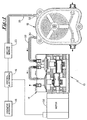
- Figure 1 is a schematic diagram showing the components of the present invention;
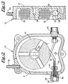
- Figure 2 is a cross sectional view of the vacuum chamber in accordance with the present invention showing a single lumen tube;
- Figure 3 is a cross sectional view of the vacuum chamber of Figure 2;
- Figure 4 is a cross sectional view of the vacuum chamber in accordance with the present invention showing a multiple lumen tube;
- Figure 5 is a cross sectional view of the vacuum chamber of Figure 4;
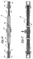
- Figure 6 is a cross sectional view of a transfer line having a single lumen according to the present invention;
- Figure 7 is a cross sectional view of a transfer line having a multiple lumen according to the present invention;
- Figure 8 is a cross sectional view of the vacuum pump of the present invention; and
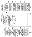
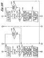
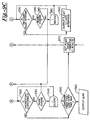
- Figures 9A, 9B and 9C are a flow chart showing the two modes of operation of the invention.
-
- The advantages enumerated above together with other features and advances represented by the present invention will now be presented in terms of a detailed embodiment described with reference to the attached drawing Figures which are intended to be but representative of many possible configurations of the invention. Other embodiments and aspects of the invention are recognized as being within the grasp of those having ordinary skill in the art. With particular initial reference to Figure 1, there is shown generally at 10 a vacuum degassing system having a
vacuum chamber 12, avacuum pump 14 and avacuum sensor 20 operably coupled to thevacuum chamber 12, an electronic control means 16 operably coupled to thevacuum pump 14 and to thevacuum sensor 20, and anoperator interface 18 operably coupled to the control means 16. - The
vacuum chamber 12 is preferably made of high-impact polymer material, such as high-density polyethylene or polypropylene, which can be readily assembled with sealing O-rings or heat welded together to form a strong, relatively inert,non-metallic housing 21. A single lumen degassing tube is shown schematically in Figure 2 at 22 as being loosely constrained by a central shaft orspool member 24 to form a coil. In the preferred embodiment the degassing tube is made from an amorphous perfluorinated copolymer such as Teflon AF. Thetube 22 is connected between inlet andoutlet connections vacuum chamber 12 further contains a connection as at 30 for avacuum line 32, which is designed to be connected to thevacuum pump 14. Additionally, a connection as at 33 for avacuum line 35 operably coupled to thevacuum sensor 20 is shown. - The inlet and outlet connections as at 26 and 28 include a short length of
interface tubing 34 which may be high strength, high density, relatively inert material, such as PEEK or, if metal, titanium or stainless steel and having an end as at 36 over which thedegassing tube 22 is fitted. Theinterface tube 34 is further connected using anappropriate sealing ferrule 38 which may be of TEFZEL or other high impact inert material used in conjunction with anut 40 to connect to thebulkhead union 42. - In accordance with an important aspect of the invention, a
multiple lumen tubing 44 made from Teflon AF is shown schematically in Figure 4 at 44 as being loosely constrained by a central shaft orspool member 46 to form a coil. A pair ofinterface grids 48 preferably in a form of a TEFZEL reverse or inverted ferrule, each positioned between a bulkhead fitting as at 42 and an inlet or outlet nut as at 40 is fabricated of stainless steel, KEL-F or PEEK for use with themultiple lumen tube 44 and includes a center bore 50 and a plurality of radially spaced bores 52 for sealingly receiving the tubes in an adhesiveless manner withnut 40 compressing reverse orinverted ferrule 48 when the tubes are pulled through during assembly of thedegassing chamber 12. - With reference to Figure 6, an alternative embodiment of the present invention generally designated 60 is shown. The
alternative embodiment 60 comprises a degassing transfer line in the form of anelongate tube 61 for use in interconnecting liquid chromatography system components. A length of gaspermeable tube 62, preferably Teflon AF, extends between opposite ends 64 and 66 of the transfer line. An enclosedinterior portion 68 of theelongate tube 61 is formed by sealing opposed ends 70 and 72 of an adhesive-lined, heat shrinkable material about spaced sections of a PTFE/FEP dual-shrink tubing 71 and 73 disposed in surrounding relationship to thetube 62. Distally of the opposed ends 70 and 72, a pair ofnuts ferrules tubing 71 and 73 for connecting the transfer line between liquid chromatography system components. Avacuum adapter 82 is provided for communication between theinterior portion 68 of theelongate tube 61 and a vacuum source to evacuate theinterior portion 68 and thereby degass the mobile phase as it flows through thetube 62. - An alternative embodiment of the transfer line is shown in Figure 7 and generally designated 90. The
degassing transfer line 90 is similar to thetransfer line 60 but is provided with amultiple lumen tube 92 in place of thesingle lumen tube 62. - In accordance with another important aspect of the present invention, a variable
speed vacuum pump 14 is operable in a first mode of operation to continuously evacuate thevacuum chamber 20 or to intermittently evacuate thevacuum chamber 20 in a second mode of operation. Thevacuum pump 14 is shown in Figure 8 and includes a two stage, series diaphragm pumping mechanism. A manifold 100 includes afirst stage head 102 and asecond stage head 104. The manifold further includes an intakeduckbill check valve 106 associated with the first stage and an outtakeduckbill check valve 108 associated with the second stage. The first and second stages are in fluid flow communication with each other through atube 109 attached to the first stage through aduckbill check valve 110 and attached to the second stage through abarbed fitting 112. A vent frit including a sinteredmetal plug 114 provides a precise vent or bleed (precision flow restrictor from Mott metallurgical) to vent solvent vapors that may build up. Furthermore, the "precision leak" of the sintered metal plug advantageously replaces the solenoid operated vent valve which has been typically utilized. This bleed feature is normally placed in the first stage during the intake stroke thereof to prevent the buildup of vapor and to reduce the exposure of the pump diaphragm to degassed vapors entering the first stage and thereby reduce diaphragm and check-valve swelling and prolong the useful life of thevacuum pump 14. As further described hereinbelow, during the exhaust stroke of the first stage, the second stage is on its intake stroke which ensures very little leakage to the outside. - A unitary diaphragm 116 extends from the first stage to the second stage. In the first stage, the diaphragm 116 is affixed to a
rod 118 by means of a press fit pin or screw 120 received in abore 122 formed in therod 118. Awasher 124 and O-ring 126 seal the diaphragm 116 to therod 118. The diaphragm 116 is affixed to arod 128 in the second stage in a similar fashion. The diaphragm 116 is preferably formed of PTFE which is inert and tolerant to exposure to common liquid chromatography solvents and vapors thereby insuring the longevity of the diaphragm 116. -
Rods shaft 130 coupled to amotor 132 at one end thereof. Theshaft 130 is rotatably supported in a frame by means of spacedball bearings rods shaft 130 by means ofneedle bearings eccentric portions shaft 130. By this arrangement, rotation of theshaft 130 results in reciprocal motion of the first and second stages 180 degrees out of phase with one another. - The
motor 132 is preferably a brushless dc stepper motor responsive to control means providing for closed loop control thereof. Apressure sensor 20 is operable to sense the vacuum level inside thevacuum chamber 12 and generate a voltage output which is ratiometric to the vacuum level and a supply voltage. The sensor output is amplified by an instrumentation amplifier and is then converted to a pulse width modulated signal which is sent to a microcontroller. A high-current pulse width modulated, uni-polar controller chip operably coupled to the microcontroller drives themotor 132 in such manner that in a first continuous mode of operation, themotor 132 runs at a high speed to quickly evacuate the vacuum chamber and at a low speed for continuous operation of the degassing system. A second intermittent mode of operation is provided wherein a vacuum setpoint is set and the pump is intermittently driven at the high speed when the sensed vacuum falls below the setpoint. - Firmware embedded in the microcontroller of the present invention provides for a user interface allowing for selection of either mode of operation as shown at 170 in Figure 9. In the first continuous mode of operation (210), the vacuum level is optionally displayed (220). To indicate that the vacuum degassing system is not yet operable, "not ready" is displayed (230). A setpoint is then obtained for comparison to the vacuum level in the vacuum chamber 12 (240). The setpoint may be entered by the user or optionally programmed in the firmware. A pump down timer is next set for five minutes (250). The pump is then driven at the high speed to evacuate the vacuum chamber 12 (260). The vacuum sensor value is read (270) and if after a one second delay (280) it is less than the set point (290), the pump is driven at the high speed if the user has not changed the mode of operation (300). If the sensed vacuum is greater than the setpoint then the vacuum pump is driven at the lower speed and a value for a leak condition setpoint is read (310). The sensed vacuum value is then read (320) and if the value is less than the leak condition setpoint "leak" is displayed to the user (360). If the sensed vacuum value is greater than the lead condition setpoint then a change in mode of operation is checked for (340). If the user has selected the second intermittent mode of operation, then the program jumps to (200). If the user has not changed the mode of operation then after a one second delay (350) the sensed vacuum value is again compared to the leak condition setpoint (330) and the loop is repeated until either the user selects a different mode of operation or the sensed vacuum level falls below the leak condition setpoint.
- In the second intermittent mode of operation (400) the vacuum level option selected is displayed (410) and to indicate that the vacuum degassing system is not yet operable, "not ready" is displayed (420). A setpoint is then obtained for comparison to the vacuum level in the vacuum chamber 12 (430). The setpoint may be entered by the user or optionally programmed in the firmware. A pump down timer is next set for five minutes (440). The pump is then driven at the high speed to evacuate the vacuum chamber 12 (450). The vacuum sensor value is read (460) and if after a one second delay (470) it is less than the set point (290), the pump is driven at the high speed if the user has not changed the mode of operation (490). If the sensed vacuum is greater than the setpoint then the vacuum pump is turned off and a "ready" indication is displayed (500). A hysteresis value and a leakdown time are also read from memory (500). The sensed vacuum value is then read (510) and if the value is greater than the setpoint plus the hysteresis value (520) then the leakdown time is compared to a maximum leakdown time (550). If the sensed vacuum value is greater than the setpoint plus the hysteresis value a change of mode of operation is checked for (530). If the user has changed modes, then the system jumps to (170). If the user has not changed modes, then after a one second delay (540), the system loops back to (520) and the sensed vacuum value is again compared to the setpoint value plus the hysteresis value. If the sensed vacuum value is less than the setpoint plus the hysteresis value the leakdown time is compared to the maximum leakdown time (550). If the leakdown time is less than the maximum leakdown time a "leak" indication is displayed (560). If the leakdown time is greater than the maximum leakdown time the pump down time is set for one minute (570) and the system jumps to (450) to drive the pump at the high speed to evacuate the vacuum chamber 12 (450).
- The invention has been described herein in considerable detail in order to comply with the Patent Statutes and to provide those skilled in the art with the information needed to apply the novel principles and to construct and use embodiments of the example as required. However, it is to be understood that the invention can be carried out by specifically different devices and that various modifications can be accomplished without departing from the scope of the invention itself.
Claims (12)
- A flow-through vacuum degassing unit for degassing one or more liquids comprising:a vacuum chamber adapted to be connected to a source for creating a vacuum in the chamber;an inlet and outlet connection for admitting and discharging liquid to be degassed;a continuous tube for conducting the liquid through the chamber, the tube being connected between the inlet and the outlet connection and each tube being formed of a polymeric material permeable to pass dissolved gasses therethrough but liquid impermeable; andcontrol means for operating the source for creating a vacuum in the chamber responsive to a sensed vacuum level in the chamber, with said control means being designed to operate said vacuum source at a relatively rapid rate during initial pump down, and being further adapted to operate said vacuum source at a substantially steady but lower rate after the desired level of vacuum has been achieved.
- The apparatus of claim 1 wherein the continuous tube has a single lumen.
- The apparatus of claim 1 wherein the continuous tube has multiple lumens.
- The apparatus of claim 1 wherein the polymeric material consists essentially of amorphous perfluorinated copolymer.
- The apparatus of claim 4 wherein said chamber inlet and outlet connections to said continuous tube comprise inverted ferrule couplings.
- The apparatus of claim 1 wherein the source for creating a vacuum further comprises a two stage, series pump.
- The apparatus of claim 5 wherein the first stage is continuously vented through a sintered metal plug.
- The apparatus of claim 5 wherein the pump further comprises a unitary diaphragm.
- The apparatus of claim 5 wherein the pump is driven by a brushless DC stepper motor.
- The apparatus of claim 8 wherein the control means is operable to drive the stepper motor in a first mode of operation in which the stepper motor is driven at a high RPM to evacuate the vacuum chamber and at a low RPM for continuous operation of the degassing unit, and a second mode of operation in which the stepper motor is driven intermittently to maintain a set vacuum within the vacuum chamber.
- The apparatus of claim 3 wherein the vacuum chamber inlet and outlet connections further comprise an interface grid disposed between a bulkhead fitting and a nut, the interface grid being formed of TEFZEL and having a center bore and a plurality of radially spaced bores adapted for adhesiveless sealing of the multiple lumen tube therethrough.
- The apparatus of claim 1 wherein the vacuum chamber further comprises an elongate tube.
Applications Claiming Priority (2)
| Application Number | Priority Date | Filing Date | Title |
|---|---|---|---|
| US09/378,592 US6248157B1 (en) | 1999-08-20 | 1999-08-20 | Vacuum degassing |
| US378592 | 1999-08-20 |
Publications (3)
| Publication Number | Publication Date |
|---|---|
| EP1078671A2 true EP1078671A2 (en) | 2001-02-28 |
| EP1078671A3 EP1078671A3 (en) | 2001-09-26 |
| EP1078671B1 EP1078671B1 (en) | 2003-04-02 |
Family
ID=23493750
Family Applications (1)
| Application Number | Title | Priority Date | Filing Date |
|---|---|---|---|
| EP00300595A Expired - Lifetime EP1078671B1 (en) | 1999-08-20 | 2000-01-27 | Vacuum degassing |
Country Status (10)
| Country | Link |
|---|---|
| US (3) | US6248157B1 (en) |
| EP (1) | EP1078671B1 (en) |
| JP (1) | JP3499188B2 (en) |
| AT (1) | ATE235947T1 (en) |
| AU (1) | AU756438B2 (en) |
| CA (1) | CA2307480A1 (en) |
| DE (1) | DE60001884T2 (en) |
| DK (1) | DK1078671T3 (en) |
| ES (1) | ES2199741T3 (en) |
| PT (1) | PT1078671E (en) |
Cited By (8)
| Publication number | Priority date | Publication date | Assignee | Title |
|---|---|---|---|---|
| EP1275960A2 (en) * | 2001-07-10 | 2003-01-15 | Systec Inc. | Burdoin tubing in degassing and pulsation dampener application |
| EP1445610A1 (en) * | 2003-01-31 | 2004-08-11 | Systec Inc. | Integrated apparatus for degassing and blending multiple mobile phase streams |
| WO2007094242A1 (en) | 2006-02-16 | 2007-08-23 | Arkray, Inc. | Degasifier and liquid chromatograph equipped therewith |
| EP1852169A2 (en) * | 2006-05-01 | 2007-11-07 | Nitto Denko Corporation | Degassing apparatus with gas-permeable tubes |
| US7427312B2 (en) | 2005-07-13 | 2008-09-23 | Rheodyne, Llc | Integrated degassing and debubbling apparatus |
| EP1988392A1 (en) * | 2006-02-09 | 2008-11-05 | Arkray, Inc. | Liquid chromatograph |
| EP2070573A1 (en) * | 2006-09-22 | 2009-06-17 | Nitto Denko Corporation | Gas removal device |
| DE102017112262A1 (en) * | 2017-06-02 | 2018-12-06 | Agilent Technologies, Inc. - A Delaware Corporation - | Bypass for degasser |
Families Citing this family (65)
| Publication number | Priority date | Publication date | Assignee | Title |
|---|---|---|---|---|
| US6582496B1 (en) * | 2000-01-28 | 2003-06-24 | Mykrolis Corporation | Hollow fiber membrane contactor |
| US6248157B1 (en) * | 1999-08-20 | 2001-06-19 | Systec Inc. | Vacuum degassing |
| DE10021454C2 (en) * | 2000-05-03 | 2002-03-14 | Knf Neuberger Gmbh | Device for conveying moist gases |
| JP3933907B2 (en) * | 2001-10-23 | 2007-06-20 | 日本碍子株式会社 | Gas separator fixing structure and gas separator using the same |
| US6746514B2 (en) * | 2002-08-08 | 2004-06-08 | Baxter International Inc. | Gas venting device and a system and method for venting a gas from a liquid delivery system |
| EP1445010A1 (en) * | 2003-02-05 | 2004-08-11 | The Automation Partnership (Cambridge) Limited | Degassification of fluids |
| US6939392B2 (en) * | 2003-04-04 | 2005-09-06 | United Technologies Corporation | System and method for thermal management |
| US6709492B1 (en) * | 2003-04-04 | 2004-03-23 | United Technologies Corporation | Planar membrane deoxygenator |
| JP4533614B2 (en) * | 2003-10-10 | 2010-09-01 | 株式会社イーアールシー | Vacuum control system |
| US7097690B2 (en) * | 2003-10-10 | 2006-08-29 | Scimed Life Systems, Inc. | Apparatus and method for removing gasses from a liquid |
| US7713331B2 (en) * | 2003-11-05 | 2010-05-11 | Rheodyne, Llc | Axial transfer line degassing |
| US6949132B2 (en) * | 2003-11-05 | 2005-09-27 | Systel, Llc | Axial degassing transfer lines |
| WO2005080261A1 (en) * | 2004-02-17 | 2005-09-01 | Modine Manufacturing Company | Integrated fuel processor for distributed hydrogen production |
| US20050274649A1 (en) * | 2004-06-09 | 2005-12-15 | Spadaccini Louis J | Method for suppressing oxidative coke formation in liquid hydrocarbons containing metal |
| JP4584018B2 (en) * | 2005-05-09 | 2010-11-17 | 日東電工株式会社 | Deaerator |
| US7393388B2 (en) * | 2005-05-13 | 2008-07-01 | United Technologies Corporation | Spiral wound fuel stabilization unit for fuel de-oxygenation |
| US7435283B2 (en) * | 2005-05-18 | 2008-10-14 | United Technologies Corporation | Modular fuel stabilization system |
| US7465336B2 (en) * | 2005-06-09 | 2008-12-16 | United Technologies Corporation | Fuel deoxygenation system with non-planar plate members |
| US7377112B2 (en) | 2005-06-22 | 2008-05-27 | United Technologies Corporation | Fuel deoxygenation for improved combustion performance |
| CN101500692B (en) * | 2005-07-13 | 2012-05-23 | 雷奥戴纳有限公司 | Integrated degassing and debubbling apparatus |
| US20070101731A1 (en) * | 2005-09-07 | 2007-05-10 | United Technologies Corporation | Deoxygenated fuel-cooled environmental control system pre-cooler for an aircraft |
| US7615104B2 (en) * | 2005-11-03 | 2009-11-10 | United Technologies Corporation | Fuel deoxygenation system with multi-layer oxygen permeable membrane |
| US20070130956A1 (en) * | 2005-12-08 | 2007-06-14 | Chen Alexander G | Rich catalytic clean burn for liquid fuel with fuel stabilization unit |
| US7824470B2 (en) * | 2006-01-18 | 2010-11-02 | United Technologies Corporation | Method for enhancing mass transport in fuel deoxygenation systems |
| US7569099B2 (en) * | 2006-01-18 | 2009-08-04 | United Technologies Corporation | Fuel deoxygenation system with non-metallic fuel plate assembly |
| US7582137B2 (en) * | 2006-01-18 | 2009-09-01 | United Technologies Corporation | Fuel deoxygenator with non-planar fuel channel and oxygen permeable membrane |
| US20070199904A1 (en) * | 2006-02-27 | 2007-08-30 | Jonathan Thompson | Methods for treatment of organic matter in liquid |
| US7399345B2 (en) * | 2006-05-09 | 2008-07-15 | Rheodyne Llc | Capillary flow restrictor apparatus |
| US7601203B2 (en) * | 2006-07-07 | 2009-10-13 | United Technologies Corporation | Hybrid vacuum system for fuel deoxygenation |
| US8017016B2 (en) * | 2006-07-07 | 2011-09-13 | Sims Carl W | Method and apparatus for pervaporation control in chromatographic systems |
| US20090044604A1 (en) * | 2007-08-15 | 2009-02-19 | Gregor Ocvirk | Portable Measuring Facility for Determining A Medically Significant Analyte Concentration |
| WO2009048452A1 (en) * | 2007-10-13 | 2009-04-16 | Neema Hekmat | Open lumen air filtration for liquid lines |
| US8545457B2 (en) * | 2007-11-08 | 2013-10-01 | Terumo Kabushiki Kaisha | Sprayer |
| GB2477679A (en) * | 2008-10-30 | 2011-08-10 | Porous Media Corp | Venting and filtration systems with gas permeable membrane |
| KR101001904B1 (en) | 2008-11-10 | 2010-12-17 | 한국지질자원연구원 | portable vacuum pump assembly for analysis of water qulity and apparatus having the same for analysis of water qulity |
| KR101107169B1 (en) * | 2009-08-26 | 2012-01-25 | 삼성모바일디스플레이주식회사 | Apparatus for dispensing resin fluid |
| EP2480306B1 (en) | 2009-09-14 | 2016-10-26 | Random Technologies LLC | Apparatus and methods for changing the concentration of gases in liquids |
| DE102009043227A1 (en) * | 2009-09-28 | 2011-03-31 | Siemens Aktiengesellschaft | Method for automated preparation of samples for a biosensor system and apparatus for carrying it out |
| US8414684B2 (en) * | 2010-06-01 | 2013-04-09 | Dionex Corporation | High pressure degas assembly for chromatography system and method |
| US20120205314A1 (en) * | 2010-08-13 | 2012-08-16 | Davison Dale A | Gradient start up system |
| US8852668B2 (en) | 2011-03-02 | 2014-10-07 | Abbott Cardiovascular Systems Inc. | In-line bubble removal mechanism |
| US8440003B2 (en) | 2011-03-25 | 2013-05-14 | Idex Health & Science, Llc | Apparatus for pervaporation control in liquid degassing systems |
| US8430949B2 (en) | 2011-03-25 | 2013-04-30 | Idex Health & Science Llc | Apparatus for pervaporation control in liquid degassing systems |
| US8668763B2 (en) * | 2011-03-25 | 2014-03-11 | Idex Health & Science Llc | Apparatus for pervaporation control in liquid degassing systems |
| DE102011050314A1 (en) | 2011-05-12 | 2012-11-15 | Dionex Softron Gmbh | Device, particularly solvent-degassing system for high performance liquid chromatography system for executing high performance liquid chromatography method, has liquid channel separated from vacuum chamber in partial region by membrane |
| JP5926384B2 (en) | 2011-09-12 | 2016-05-25 | アイデックス ヘルス アンド サイエンス エルエルシー | Degassing supersaturated fluid |
| US9114331B2 (en) | 2012-09-28 | 2015-08-25 | Random Technologies Llc | Apparatus and method for degassing liquids |
| US9381449B2 (en) | 2013-06-06 | 2016-07-05 | Idex Health & Science Llc | Carbon nanotube composite membrane |
| US9403121B2 (en) | 2013-06-06 | 2016-08-02 | Idex Health & Science, Llc | Carbon nanotube composite membrane |
| US9370734B2 (en) | 2013-06-26 | 2016-06-21 | Idex Health & Science, Llc | Fluid degassing module with helical membrane |
| CN104020226B (en) * | 2014-05-16 | 2016-05-04 | 安徽皖仪科技股份有限公司 | The special CO of a kind of ion chromatograph2TVS performance raising method and device |
| WO2015195636A1 (en) * | 2014-06-16 | 2015-12-23 | Siemens Healthcare Diagnostics Inc. | Fluidic device and degassing method |
| US20150380278A1 (en) * | 2014-06-30 | 2015-12-31 | Lam Research Corporation | Hardware for the separation and degassing of dissolved gases in semiconductor precursor chemicals |
| DE202014104979U1 (en) | 2014-10-17 | 2014-12-08 | Bürkert Werke GmbH | degassing |
| WO2016069770A2 (en) * | 2014-10-28 | 2016-05-06 | Idex Health & Science, Llc | Axial transfer line shell side degassing |
| US9452251B2 (en) * | 2014-12-10 | 2016-09-27 | Medtronic, Inc. | Degassing membrane for dialysis |
| WO2017040408A1 (en) | 2015-08-28 | 2017-03-09 | Idex Health & Science, Llc | Membrane gas/liquid contactor |
| US10159913B2 (en) * | 2015-10-26 | 2018-12-25 | Waters Technologies Corporation | Degassing liquid eluent of a preparative SFC fluid chromatography system |
| DE102016220107B4 (en) | 2016-10-14 | 2020-01-02 | Fraunhofer-Gesellschaft zur Förderung der angewandten Forschung e.V. | degassing |
| CN107328633B (en) * | 2017-07-27 | 2024-04-02 | 防灾科技学院 | Degassing device and application thereof |
| US11000784B2 (en) | 2017-08-22 | 2021-05-11 | Hamilton Sunstrand Corporation | Vacuum system for fuel degassing |
| US11491421B2 (en) * | 2018-01-22 | 2022-11-08 | Hamilton Sundstrand Corporation | Valve controlled vacuum system |
| US11534701B2 (en) | 2018-11-28 | 2022-12-27 | Idex Health & Science, Llc | Fluid degassing control system |
| US20220348862A9 (en) * | 2019-07-12 | 2022-11-03 | Buckman Laboratories International, Inc. | System and method for optimization of the fermentation process |
| GB2590130B (en) | 2019-09-23 | 2022-10-19 | Idex Health & Science Llc | Fluid degassing system with reduced pressure pulsatility |
Citations (4)
| Publication number | Priority date | Publication date | Assignee | Title |
|---|---|---|---|---|
| US4469495A (en) * | 1983-01-29 | 1984-09-04 | Erma Optical Works, Ltd. | Method and device for degassifying liquid |
| US5205844A (en) * | 1990-11-30 | 1993-04-27 | Uniflows Co., Ltd. | Degassing apparatus |
| US5762684A (en) * | 1995-11-30 | 1998-06-09 | Dainippon Screen Mfg. Co., Ltd. | Treating liquid supplying method and apparatus |
| EP0931939A2 (en) * | 1997-12-24 | 1999-07-28 | VARIAN S.p.A. | Vacuum pump |
Family Cites Families (33)
| Publication number | Priority date | Publication date | Assignee | Title |
|---|---|---|---|---|
| GB1199440A (en) * | 1966-10-13 | 1970-07-22 | Ceskoslovenska Akademie Ved | Method of and Device for Removing Gas Bubbles in Capillary Reactors. |
| US3668837A (en) | 1970-02-13 | 1972-06-13 | Pall Corp | Separator of the semipermeable membrane type |
| US3751879A (en) * | 1971-04-26 | 1973-08-14 | Instrumentation Specialties Co | Apparatus for reducing the dissolved gas concentration in a liquid |
| US4004587A (en) * | 1975-06-13 | 1977-01-25 | Baxter Travenol Laboratories, Inc. | Parenteral liquid administration set with non-air blocking filter |
| US4430098A (en) | 1976-03-24 | 1984-02-07 | Bowman Donald B | Apparatus for degassing hemodialysis liquid and the like |
| US4325715A (en) * | 1976-03-24 | 1982-04-20 | Bowman Donald B | Apparatus for degassing hemodialysis liquid |
| US4133767A (en) | 1977-06-14 | 1979-01-09 | Spectra-Physics, Inc. | Chromatographic apparatus and method |
| SU871806A1 (en) * | 1979-12-25 | 1981-10-15 | Ордена Ленина Институт Геохимии И Аналитической Химии Им.В.И.Вернадского Ан Ссср | Method of determining helium concentration in natural waters |
| US4834877A (en) * | 1985-08-09 | 1989-05-30 | The Dow Chemical Company | Apparatus for membrane-permeation separations using segmented flow |
| JPS62204086A (en) * | 1986-03-04 | 1987-09-08 | 株式会社エルマ、シーアール | Pipe |
| JPH0326882Y2 (en) * | 1986-12-12 | 1991-06-11 | ||
| FI76488C (en) * | 1987-05-05 | 1988-11-10 | Instrumentarium Oy | ROERVATTENAVSKILJARE TILL EN GASANALYSATOR. |
| DE3822093C2 (en) * | 1987-06-30 | 1997-11-06 | Fuji Photo Film Co Ltd | Process for degassing and defoaming a photosensitive coating solution and apparatus for carrying out this process |
| US4986827A (en) * | 1987-11-05 | 1991-01-22 | Nestle S.A. | Surgical cutting instrument with reciprocating inner cutter |
| JPH01215312A (en) * | 1988-02-22 | 1989-08-29 | Takuma Co Ltd | Method for removing dissolved gas in liquid |
| US4985055A (en) * | 1988-12-19 | 1991-01-15 | The Boc Group, Inc. | Liquid/gas separation device |
| JP2780331B2 (en) * | 1989-04-28 | 1998-07-30 | 日東電工株式会社 | Liquid degassing method |
| JP2542533B2 (en) * | 1989-11-09 | 1996-10-09 | 三菱レイヨン株式会社 | Fluorine-based separation membrane |
| JPH03224602A (en) * | 1990-01-31 | 1991-10-03 | Suido Kiko Kk | Device for adjusting dissolved gas concentration in liquid |
| US4994180A (en) | 1990-02-01 | 1991-02-19 | Systec, Inc. | Solvent handling system |
| US4997464A (en) * | 1990-03-23 | 1991-03-05 | Kopf Henry B | Deaeration apparatus |
| US5183486A (en) | 1990-12-04 | 1993-02-02 | Spectra-Physics, Inc. | Apparatus for degassing a liquid |
| JPH0568808A (en) * | 1991-06-17 | 1993-03-23 | Dainippon Ink & Chem Inc | Equipment and method for diaphragm vacuum deaeration |
| JP3224409B2 (en) * | 1992-01-08 | 2001-10-29 | 三菱レイヨン株式会社 | Hollow fiber membrane module for degassing |
| WO1994003397A1 (en) * | 1992-08-07 | 1994-02-17 | Miura Co., Ltd. | Improvement to membrane type deaerator |
| US5383483A (en) * | 1992-10-14 | 1995-01-24 | Shibano; Yoshihide | Ultrasonic cleaning and deburring apparatus |
| EP0598424A3 (en) * | 1992-11-16 | 1996-05-15 | Novellus Systems Inc | Device for removing dissolved gas from a liquid. |
| US5340384A (en) | 1993-03-05 | 1994-08-23 | Systec, Inc. | Vacuum degassing |
| JPH0760005A (en) * | 1993-08-31 | 1995-03-07 | Miura Co Ltd | Dearation of liquid product |
| US5743941A (en) * | 1995-06-06 | 1998-04-28 | Systec, Inc. | Bottle top solvent degasser |
| JPH11137907A (en) * | 1997-11-11 | 1999-05-25 | Moore Kk | Deaerator |
| US6042634A (en) * | 1998-04-22 | 2000-03-28 | Bacharach, Inc. | Moisture extractor system for gas sampling |
| US6248157B1 (en) * | 1999-08-20 | 2001-06-19 | Systec Inc. | Vacuum degassing |
-
1999
- 1999-08-20 US US09/378,592 patent/US6248157B1/en not_active Expired - Lifetime
-
2000
- 2000-01-27 EP EP00300595A patent/EP1078671B1/en not_active Expired - Lifetime
- 2000-01-27 ES ES00300595T patent/ES2199741T3/en not_active Expired - Lifetime
- 2000-01-27 DE DE60001884T patent/DE60001884T2/en not_active Expired - Lifetime
- 2000-01-27 PT PT00300595T patent/PT1078671E/en unknown
- 2000-01-27 DK DK00300595T patent/DK1078671T3/en active
- 2000-01-27 AT AT00300595T patent/ATE235947T1/en active
- 2000-03-23 JP JP2000082155A patent/JP3499188B2/en not_active Expired - Lifetime
- 2000-04-10 AU AU27634/00A patent/AU756438B2/en not_active Expired
- 2000-05-03 CA CA002307480A patent/CA2307480A1/en not_active Abandoned
- 2000-08-08 US US09/635,049 patent/US6309444B1/en not_active Expired - Lifetime
- 2000-12-12 US US09/735,333 patent/US6494938B2/en not_active Expired - Lifetime
Patent Citations (4)
| Publication number | Priority date | Publication date | Assignee | Title |
|---|---|---|---|---|
| US4469495A (en) * | 1983-01-29 | 1984-09-04 | Erma Optical Works, Ltd. | Method and device for degassifying liquid |
| US5205844A (en) * | 1990-11-30 | 1993-04-27 | Uniflows Co., Ltd. | Degassing apparatus |
| US5762684A (en) * | 1995-11-30 | 1998-06-09 | Dainippon Screen Mfg. Co., Ltd. | Treating liquid supplying method and apparatus |
| EP0931939A2 (en) * | 1997-12-24 | 1999-07-28 | VARIAN S.p.A. | Vacuum pump |
Cited By (18)
| Publication number | Priority date | Publication date | Assignee | Title |
|---|---|---|---|---|
| EP1275960A3 (en) * | 2001-07-10 | 2004-05-19 | Systec Inc. | Burdoin tubing in degassing and pulsation dampener application |
| EP1275960A2 (en) * | 2001-07-10 | 2003-01-15 | Systec Inc. | Burdoin tubing in degassing and pulsation dampener application |
| EP1445610A1 (en) * | 2003-01-31 | 2004-08-11 | Systec Inc. | Integrated apparatus for degassing and blending multiple mobile phase streams |
| JP2004230373A (en) * | 2003-01-31 | 2004-08-19 | Systec Inc | Integrated apparatus for degassing and blending a plurality of mobile phase streams |
| US7427312B2 (en) | 2005-07-13 | 2008-09-23 | Rheodyne, Llc | Integrated degassing and debubbling apparatus |
| EP1988392A1 (en) * | 2006-02-09 | 2008-11-05 | Arkray, Inc. | Liquid chromatograph |
| EP1988392A4 (en) * | 2006-02-09 | 2009-04-08 | Arkray Inc | Liquid chromatograph |
| EP2017615A1 (en) * | 2006-02-16 | 2009-01-21 | Arkray, Inc. | Degasifier and liquid chromatograph equipped therewith |
| WO2007094242A1 (en) | 2006-02-16 | 2007-08-23 | Arkray, Inc. | Degasifier and liquid chromatograph equipped therewith |
| EP2017615A4 (en) * | 2006-02-16 | 2009-07-29 | Arkray Inc | Degasifier and liquid chromatograph equipped therewith |
| CN101421611B (en) * | 2006-02-16 | 2012-09-19 | 爱科来株式会社 | Degasifier and liquid chromatograph equipped therewith |
| US8495906B2 (en) | 2006-02-16 | 2013-07-30 | Arkray, Inc. | Degasifier and liquid chromatograph equipped therewith |
| EP1852169A2 (en) * | 2006-05-01 | 2007-11-07 | Nitto Denko Corporation | Degassing apparatus with gas-permeable tubes |
| EP1852169A3 (en) * | 2006-05-01 | 2010-06-30 | Nitto Denko Corporation | Degassing apparatus with gas-permeable tubes |
| EP2070573A1 (en) * | 2006-09-22 | 2009-06-17 | Nitto Denko Corporation | Gas removal device |
| EP2070573A4 (en) * | 2006-09-22 | 2011-06-15 | Nitto Denko Corp | Gas removal device |
| US8177889B2 (en) | 2006-09-22 | 2012-05-15 | Nitto Denko Corporation | Gas removal device |
| DE102017112262A1 (en) * | 2017-06-02 | 2018-12-06 | Agilent Technologies, Inc. - A Delaware Corporation - | Bypass for degasser |
Also Published As
| Publication number | Publication date |
|---|---|
| EP1078671B1 (en) | 2003-04-02 |
| DE60001884D1 (en) | 2003-05-08 |
| PT1078671E (en) | 2003-08-29 |
| US20010037731A1 (en) | 2001-11-08 |
| CA2307480A1 (en) | 2001-02-20 |
| EP1078671A3 (en) | 2001-09-26 |
| ES2199741T3 (en) | 2004-03-01 |
| US6494938B2 (en) | 2002-12-17 |
| DE60001884T2 (en) | 2004-01-29 |
| AU2763400A (en) | 2001-02-22 |
| DK1078671T3 (en) | 2003-07-21 |
| US6309444B1 (en) | 2001-10-30 |
| JP3499188B2 (en) | 2004-02-23 |
| AU756438B2 (en) | 2003-01-16 |
| ATE235947T1 (en) | 2003-04-15 |
| JP2001074718A (en) | 2001-03-23 |
| US6248157B1 (en) | 2001-06-19 |
Similar Documents
| Publication | Publication Date | Title |
|---|---|---|
| US6248157B1 (en) | Vacuum degassing | |
| EP0275933B1 (en) | Pressure control apparatus | |
| US5703359A (en) | Composite membrane and support assembly | |
| EP0429397B1 (en) | Method and apparatus for monitoring gas concentrations in a fluid | |
| JP5121825B2 (en) | Method and apparatus for controlling pervaporation in a chromatography system | |
| JP4533614B2 (en) | Vacuum control system | |
| US5795368A (en) | Microtrap sample concentrator and methods of use | |
| US5786529A (en) | Search gas detector with vacuum pump and process for operating such a search gas detector | |
| US7028562B2 (en) | Vacuum membrane extraction system | |
| US3661010A (en) | Fluid sample analyzing apparatus | |
| EP1396713A1 (en) | Method and Apparatus for concentrating a gaseous substance | |
| US20190339241A1 (en) | Gas detection apparatus | |
| JP3322325B2 (en) | Sample concentrator for analysis | |
| US6133567A (en) | Probe for the measurement of gas tensions | |
| JP2002005912A (en) | Gas analytical system using gas chromatograph | |
| US20230364610A1 (en) | Membrane inlet for chemical analysis with sample degassing | |
| JPS60255120A (en) | Deaeration apparatus | |
| US11504650B2 (en) | Fluid degassing system with reduced pressure pulsatility | |
| CN108554207B (en) | Low-concentration standard gas continuous generation device and generation method thereof | |
| JP3528057B2 (en) | Degassing device | |
| Ortega et al. | A recirculation system for the determination of blood gases by gas chromatography. | |
| Zaromb et al. | Simple permeation absorber for sampling and preconcentrating hazardous air contaminants |
Legal Events
| Date | Code | Title | Description |
|---|---|---|---|
| PUAI | Public reference made under article 153(3) epc to a published international application that has entered the european phase |
Free format text: ORIGINAL CODE: 0009012 |
|
| AK | Designated contracting states |
Kind code of ref document: A2 Designated state(s): AT BE CH CY DE DK ES FI FR GB GR IE IT LI LU MC NL PT SE |
|
| AX | Request for extension of the european patent |
Free format text: AL;LT;LV;MK;RO;SI |
|
| PUAL | Search report despatched |
Free format text: ORIGINAL CODE: 0009013 |
|
| AK | Designated contracting states |
Kind code of ref document: A3 Designated state(s): AT BE CH CY DE DK ES FI FR GB GR IE IT LI LU MC NL PT SE |
|
| AX | Request for extension of the european patent |
Free format text: AL;LT;LV;MK;RO;SI |
|
| 17P | Request for examination filed |
Effective date: 20011019 |
|
| 17Q | First examination report despatched |
Effective date: 20020228 |
|
| AKX | Designation fees paid |
Free format text: AT BE CH CY DE DK ES FI FR GB GR IE IT LI LU MC NL PT SE |
|
| GRAH | Despatch of communication of intention to grant a patent |
Free format text: ORIGINAL CODE: EPIDOS IGRA |
|
| GRAH | Despatch of communication of intention to grant a patent |
Free format text: ORIGINAL CODE: EPIDOS IGRA |
|
| GRAA | (expected) grant |
Free format text: ORIGINAL CODE: 0009210 |
|
| AK | Designated contracting states |
Designated state(s): AT BE CH CY DE DK ES FI FR GB GR IE IT LI LU MC NL PT SE |
|
| PG25 | Lapsed in a contracting state [announced via postgrant information from national office to epo] |
Ref country code: CY Free format text: LAPSE BECAUSE OF FAILURE TO SUBMIT A TRANSLATION OF THE DESCRIPTION OR TO PAY THE FEE WITHIN THE PRESCRIBED TIME-LIMIT Effective date: 20030402 |
|
| REG | Reference to a national code |
Ref country code: GB Ref legal event code: FG4D |
|
| REG | Reference to a national code |
Ref country code: SE Ref legal event code: TRGR |
|
| REG | Reference to a national code |
Ref country code: CH Ref legal event code: EP |
|
| REG | Reference to a national code |
Ref country code: IE Ref legal event code: FG4D |
|
| REF | Corresponds to: |
Ref document number: 60001884 Country of ref document: DE Date of ref document: 20030508 Kind code of ref document: P |
|
| PG25 | Lapsed in a contracting state [announced via postgrant information from national office to epo] |
Ref country code: GR Free format text: LAPSE BECAUSE OF FAILURE TO SUBMIT A TRANSLATION OF THE DESCRIPTION OR TO PAY THE FEE WITHIN THE PRESCRIBED TIME-LIMIT Effective date: 20030702 |
|
| REG | Reference to a national code |
Ref country code: CH Ref legal event code: NV Representative=s name: PATENTBUERO PAUL ROSENICH AG |
|
| REG | Reference to a national code |
Ref country code: DK Ref legal event code: T3 |
|
| ET | Fr: translation filed | ||
| PG25 | Lapsed in a contracting state [announced via postgrant information from national office to epo] |
Ref country code: IE Free format text: LAPSE BECAUSE OF NON-PAYMENT OF DUE FEES Effective date: 20040127 Ref country code: LU Free format text: LAPSE BECAUSE OF NON-PAYMENT OF DUE FEES Effective date: 20040127 |
|
| PG25 | Lapsed in a contracting state [announced via postgrant information from national office to epo] |
Ref country code: MC Free format text: LAPSE BECAUSE OF NON-PAYMENT OF DUE FEES Effective date: 20040131 |
|
| PLBE | No opposition filed within time limit |
Free format text: ORIGINAL CODE: 0009261 |
|
| STAA | Information on the status of an ep patent application or granted ep patent |
Free format text: STATUS: NO OPPOSITION FILED WITHIN TIME LIMIT |
|
| REG | Reference to a national code |
Ref country code: ES Ref legal event code: FG2A Ref document number: 2199741 Country of ref document: ES Kind code of ref document: T3 |
|
| 26N | No opposition filed |
Effective date: 20040105 |
|
| REG | Reference to a national code |
Ref country code: IE Ref legal event code: MM4A |
|
| REG | Reference to a national code |
Ref country code: PT Ref legal event code: PD4A Owner name: SYSTEC LLC, US Effective date: 20071221 Ref country code: PT Ref legal event code: PC4A Owner name: RHEODYNE, LLC, US Effective date: 20071221 Ref country code: PT Ref legal event code: PC4A Owner name: SYSTEC ACQUISITION LLC, US Effective date: 20071221 |
|
| REG | Reference to a national code |
Ref country code: CH Ref legal event code: PUE Owner name: RHEODYNE, LLC Free format text: SYSTEC INC.#213 OLD HIGHWAY 8#NEW BRIGHTON, MINNESOTA 55112 (US) -TRANSFER TO- RHEODYNE, LLC#600 PARK COURT#ROHNERT PARK, CA 94928 (US) |
|
| REG | Reference to a national code |
Ref country code: GB Ref legal event code: 732E |
|
| REG | Reference to a national code |
Ref country code: FR Ref legal event code: CA Ref country code: FR Ref legal event code: TP Ref country code: FR Ref legal event code: CD |
|
| REG | Reference to a national code |
Ref country code: CH Ref legal event code: NV Representative=s name: R. A. EGLI & CO. PATENTANWAELTE |
|
| REG | Reference to a national code |
Ref country code: FR Ref legal event code: PLFP Year of fee payment: 17 |
|
| REG | Reference to a national code |
Ref country code: FR Ref legal event code: PLFP Year of fee payment: 18 |
|
| REG | Reference to a national code |
Ref country code: FR Ref legal event code: PLFP Year of fee payment: 19 |
|
| PGFP | Annual fee paid to national office [announced via postgrant information from national office to epo] |
Ref country code: PT Payment date: 20181218 Year of fee payment: 20 |
|
| PGFP | Annual fee paid to national office [announced via postgrant information from national office to epo] |
Ref country code: ES Payment date: 20190226 Year of fee payment: 20 Ref country code: NL Payment date: 20190121 Year of fee payment: 20 Ref country code: DE Payment date: 20190123 Year of fee payment: 20 Ref country code: CH Payment date: 20190123 Year of fee payment: 20 Ref country code: FI Payment date: 20190122 Year of fee payment: 20 Ref country code: GB Payment date: 20190121 Year of fee payment: 20 Ref country code: FR Payment date: 20190123 Year of fee payment: 20 Ref country code: IT Payment date: 20190124 Year of fee payment: 20 |
|
| PGFP | Annual fee paid to national office [announced via postgrant information from national office to epo] |
Ref country code: AT Payment date: 20190122 Year of fee payment: 20 Ref country code: DK Payment date: 20190123 Year of fee payment: 20 Ref country code: BE Payment date: 20190121 Year of fee payment: 20 Ref country code: SE Payment date: 20190121 Year of fee payment: 20 |
|
| REG | Reference to a national code |
Ref country code: DE Ref legal event code: R071 Ref document number: 60001884 Country of ref document: DE |
|
| REG | Reference to a national code |
Ref country code: NL Ref legal event code: MK Effective date: 20200126 |
|
| REG | Reference to a national code |
Ref country code: DK Ref legal event code: EUP Effective date: 20200127 |
|
| REG | Reference to a national code |
Ref country code: GB Ref legal event code: PE20 Expiry date: 20200126 |
|
| REG | Reference to a national code |
Ref country code: FI Ref legal event code: MAE |
|
| REG | Reference to a national code |
Ref country code: SE Ref legal event code: EUG |
|
| REG | Reference to a national code |
Ref country code: AT Ref legal event code: MK07 Ref document number: 235947 Country of ref document: AT Kind code of ref document: T Effective date: 20200127 |
|
| REG | Reference to a national code |
Ref country code: BE Ref legal event code: MK Effective date: 20200127 |
|
| REG | Reference to a national code |
Ref country code: CH Ref legal event code: PL |
|
| PG25 | Lapsed in a contracting state [announced via postgrant information from national office to epo] |
Ref country code: GB Free format text: LAPSE BECAUSE OF EXPIRATION OF PROTECTION Effective date: 20200126 Ref country code: PT Free format text: LAPSE BECAUSE OF EXPIRATION OF PROTECTION Effective date: 20200206 |
|
| REG | Reference to a national code |
Ref country code: ES Ref legal event code: FD2A Effective date: 20220128 |
|
| PG25 | Lapsed in a contracting state [announced via postgrant information from national office to epo] |
Ref country code: ES Free format text: LAPSE BECAUSE OF EXPIRATION OF PROTECTION Effective date: 20200128 |