EP1075218B1 - Adjustable blood filtration system - Google Patents
Adjustable blood filtration system Download PDFInfo
- Publication number
- EP1075218B1 EP1075218B1 EP99921459A EP99921459A EP1075218B1 EP 1075218 B1 EP1075218 B1 EP 1075218B1 EP 99921459 A EP99921459 A EP 99921459A EP 99921459 A EP99921459 A EP 99921459A EP 1075218 B1 EP1075218 B1 EP 1075218B1
- Authority
- EP
- European Patent Office
- Prior art keywords
- frame
- filter
- shaft
- proximal
- cartridge
- Prior art date
- Legal status (The legal status is an assumption and is not a legal conclusion. Google has not performed a legal analysis and makes no representation as to the accuracy of the status listed.)
- Expired - Lifetime
Links
Images


Classifications
-
- A—HUMAN NECESSITIES
- A61—MEDICAL OR VETERINARY SCIENCE; HYGIENE
- A61F—FILTERS IMPLANTABLE INTO BLOOD VESSELS; PROSTHESES; DEVICES PROVIDING PATENCY TO, OR PREVENTING COLLAPSING OF, TUBULAR STRUCTURES OF THE BODY, e.g. STENTS; ORTHOPAEDIC, NURSING OR CONTRACEPTIVE DEVICES; FOMENTATION; TREATMENT OR PROTECTION OF EYES OR EARS; BANDAGES, DRESSINGS OR ABSORBENT PADS; FIRST-AID KITS
- A61F2/00—Filters implantable into blood vessels; Prostheses, i.e. artificial substitutes or replacements for parts of the body; Appliances for connecting them with the body; Devices providing patency to, or preventing collapsing of, tubular structures of the body, e.g. stents
- A61F2/01—Filters implantable into blood vessels
- A61F2/011—Instruments for their placement or removal
-
- A—HUMAN NECESSITIES
- A61—MEDICAL OR VETERINARY SCIENCE; HYGIENE
- A61B—DIAGNOSIS; SURGERY; IDENTIFICATION
- A61B90/00—Instruments, implements or accessories specially adapted for surgery or diagnosis and not covered by any of the groups A61B1/00 - A61B50/00, e.g. for luxation treatment or for protecting wound edges
- A61B90/06—Measuring instruments not otherwise provided for
-
- A—HUMAN NECESSITIES
- A61—MEDICAL OR VETERINARY SCIENCE; HYGIENE
- A61F—FILTERS IMPLANTABLE INTO BLOOD VESSELS; PROSTHESES; DEVICES PROVIDING PATENCY TO, OR PREVENTING COLLAPSING OF, TUBULAR STRUCTURES OF THE BODY, e.g. STENTS; ORTHOPAEDIC, NURSING OR CONTRACEPTIVE DEVICES; FOMENTATION; TREATMENT OR PROTECTION OF EYES OR EARS; BANDAGES, DRESSINGS OR ABSORBENT PADS; FIRST-AID KITS
- A61F2/00—Filters implantable into blood vessels; Prostheses, i.e. artificial substitutes or replacements for parts of the body; Appliances for connecting them with the body; Devices providing patency to, or preventing collapsing of, tubular structures of the body, e.g. stents
- A61F2/01—Filters implantable into blood vessels
- A61F2/0105—Open ended, i.e. legs gathered only at one side
-
- A—HUMAN NECESSITIES
- A61—MEDICAL OR VETERINARY SCIENCE; HYGIENE
- A61F—FILTERS IMPLANTABLE INTO BLOOD VESSELS; PROSTHESES; DEVICES PROVIDING PATENCY TO, OR PREVENTING COLLAPSING OF, TUBULAR STRUCTURES OF THE BODY, e.g. STENTS; ORTHOPAEDIC, NURSING OR CONTRACEPTIVE DEVICES; FOMENTATION; TREATMENT OR PROTECTION OF EYES OR EARS; BANDAGES, DRESSINGS OR ABSORBENT PADS; FIRST-AID KITS
- A61F2/00—Filters implantable into blood vessels; Prostheses, i.e. artificial substitutes or replacements for parts of the body; Appliances for connecting them with the body; Devices providing patency to, or preventing collapsing of, tubular structures of the body, e.g. stents
- A61F2/01—Filters implantable into blood vessels
- A61F2/0108—Both ends closed, i.e. legs gathered at both ends
-
- A—HUMAN NECESSITIES
- A61—MEDICAL OR VETERINARY SCIENCE; HYGIENE
- A61F—FILTERS IMPLANTABLE INTO BLOOD VESSELS; PROSTHESES; DEVICES PROVIDING PATENCY TO, OR PREVENTING COLLAPSING OF, TUBULAR STRUCTURES OF THE BODY, e.g. STENTS; ORTHOPAEDIC, NURSING OR CONTRACEPTIVE DEVICES; FOMENTATION; TREATMENT OR PROTECTION OF EYES OR EARS; BANDAGES, DRESSINGS OR ABSORBENT PADS; FIRST-AID KITS
- A61F2/00—Filters implantable into blood vessels; Prostheses, i.e. artificial substitutes or replacements for parts of the body; Appliances for connecting them with the body; Devices providing patency to, or preventing collapsing of, tubular structures of the body, e.g. stents
- A61F2/01—Filters implantable into blood vessels
- A61F2/012—Multiple filtering units
-
- A—HUMAN NECESSITIES
- A61—MEDICAL OR VETERINARY SCIENCE; HYGIENE
- A61F—FILTERS IMPLANTABLE INTO BLOOD VESSELS; PROSTHESES; DEVICES PROVIDING PATENCY TO, OR PREVENTING COLLAPSING OF, TUBULAR STRUCTURES OF THE BODY, e.g. STENTS; ORTHOPAEDIC, NURSING OR CONTRACEPTIVE DEVICES; FOMENTATION; TREATMENT OR PROTECTION OF EYES OR EARS; BANDAGES, DRESSINGS OR ABSORBENT PADS; FIRST-AID KITS
- A61F2/00—Filters implantable into blood vessels; Prostheses, i.e. artificial substitutes or replacements for parts of the body; Appliances for connecting them with the body; Devices providing patency to, or preventing collapsing of, tubular structures of the body, e.g. stents
- A61F2/01—Filters implantable into blood vessels
- A61F2002/018—Filters implantable into blood vessels made from tubes or sheets of material, e.g. by etching or laser-cutting
-
- A—HUMAN NECESSITIES
- A61—MEDICAL OR VETERINARY SCIENCE; HYGIENE
- A61F—FILTERS IMPLANTABLE INTO BLOOD VESSELS; PROSTHESES; DEVICES PROVIDING PATENCY TO, OR PREVENTING COLLAPSING OF, TUBULAR STRUCTURES OF THE BODY, e.g. STENTS; ORTHOPAEDIC, NURSING OR CONTRACEPTIVE DEVICES; FOMENTATION; TREATMENT OR PROTECTION OF EYES OR EARS; BANDAGES, DRESSINGS OR ABSORBENT PADS; FIRST-AID KITS
- A61F2230/00—Geometry of prostheses classified in groups A61F2/00 - A61F2/26 or A61F2/82 or A61F9/00 or A61F11/00 or subgroups thereof
- A61F2230/0002—Two-dimensional shapes, e.g. cross-sections
- A61F2230/0004—Rounded shapes, e.g. with rounded corners
- A61F2230/0006—Rounded shapes, e.g. with rounded corners circular
-
- A—HUMAN NECESSITIES
- A61—MEDICAL OR VETERINARY SCIENCE; HYGIENE
- A61F—FILTERS IMPLANTABLE INTO BLOOD VESSELS; PROSTHESES; DEVICES PROVIDING PATENCY TO, OR PREVENTING COLLAPSING OF, TUBULAR STRUCTURES OF THE BODY, e.g. STENTS; ORTHOPAEDIC, NURSING OR CONTRACEPTIVE DEVICES; FOMENTATION; TREATMENT OR PROTECTION OF EYES OR EARS; BANDAGES, DRESSINGS OR ABSORBENT PADS; FIRST-AID KITS
- A61F2230/00—Geometry of prostheses classified in groups A61F2/00 - A61F2/26 or A61F2/82 or A61F9/00 or A61F11/00 or subgroups thereof
- A61F2230/0063—Three-dimensional shapes
- A61F2230/0067—Three-dimensional shapes conical
-
- A—HUMAN NECESSITIES
- A61—MEDICAL OR VETERINARY SCIENCE; HYGIENE
- A61F—FILTERS IMPLANTABLE INTO BLOOD VESSELS; PROSTHESES; DEVICES PROVIDING PATENCY TO, OR PREVENTING COLLAPSING OF, TUBULAR STRUCTURES OF THE BODY, e.g. STENTS; ORTHOPAEDIC, NURSING OR CONTRACEPTIVE DEVICES; FOMENTATION; TREATMENT OR PROTECTION OF EYES OR EARS; BANDAGES, DRESSINGS OR ABSORBENT PADS; FIRST-AID KITS
- A61F2230/00—Geometry of prostheses classified in groups A61F2/00 - A61F2/26 or A61F2/82 or A61F9/00 or A61F11/00 or subgroups thereof
- A61F2230/0063—Three-dimensional shapes
- A61F2230/0071—Three-dimensional shapes spherical
-
- A—HUMAN NECESSITIES
- A61—MEDICAL OR VETERINARY SCIENCE; HYGIENE
- A61F—FILTERS IMPLANTABLE INTO BLOOD VESSELS; PROSTHESES; DEVICES PROVIDING PATENCY TO, OR PREVENTING COLLAPSING OF, TUBULAR STRUCTURES OF THE BODY, e.g. STENTS; ORTHOPAEDIC, NURSING OR CONTRACEPTIVE DEVICES; FOMENTATION; TREATMENT OR PROTECTION OF EYES OR EARS; BANDAGES, DRESSINGS OR ABSORBENT PADS; FIRST-AID KITS
- A61F2230/00—Geometry of prostheses classified in groups A61F2/00 - A61F2/26 or A61F2/82 or A61F9/00 or A61F11/00 or subgroups thereof
- A61F2230/0063—Three-dimensional shapes
- A61F2230/0073—Quadric-shaped
- A61F2230/0076—Quadric-shaped ellipsoidal or ovoid
-
- A—HUMAN NECESSITIES
- A61—MEDICAL OR VETERINARY SCIENCE; HYGIENE
- A61F—FILTERS IMPLANTABLE INTO BLOOD VESSELS; PROSTHESES; DEVICES PROVIDING PATENCY TO, OR PREVENTING COLLAPSING OF, TUBULAR STRUCTURES OF THE BODY, e.g. STENTS; ORTHOPAEDIC, NURSING OR CONTRACEPTIVE DEVICES; FOMENTATION; TREATMENT OR PROTECTION OF EYES OR EARS; BANDAGES, DRESSINGS OR ABSORBENT PADS; FIRST-AID KITS
- A61F2230/00—Geometry of prostheses classified in groups A61F2/00 - A61F2/26 or A61F2/82 or A61F9/00 or A61F11/00 or subgroups thereof
- A61F2230/0063—Three-dimensional shapes
- A61F2230/0073—Quadric-shaped
- A61F2230/008—Quadric-shaped paraboloidal
Abstract
Description
- The present invention relates generally to blood filter and associated devices for temporary placement in a blood vessel to capture embolic material, and more particularly to a hollow vessel insertion device with an adjustable filter apparatus for placement in a blood vessel to carry blood to the vessel and to entrap embolic material in the vessel, for example when delivering blood to the aorta from a bypass-oxygenator system during cardiac surgery.
- During cardiac surgery, it is often necessary to introduce a cannula into an artery or other blood vessel. For example, an arterial cannula is typically introduced into the aorta to deliver blood from a bypass-oxygenator system. Such a cannula generally includes a proximal end for receiving blood from a bypass-oxygenator machine, a distal end for entry into an artery and a lumen extending between the proximal and distal ends.
- One concern with such procedures is that calcified plaque or other embolic material may be dislodged, particularly when clamping or unclamping arteries such as the aorta. See Barbut et al., "Cerebral Emboli Detected During Bypass Surgery Are Associated With Clamp Removal," Stroke, 25(12):2398-2402 (1994).
- Such embolic material may travel downstream, possibly becoming lodged in another portion of the blood vessel or possibly reaching a vital organ, such as the brain, where the material can cause substantial injury to the patient.
- For this reason, some arterial cannulas may include a blood filter device attached directly to them. For example, an expandable filter device may be mounted on the distal end of a cannula, allowing the filter to capture any loose embolic material once the cannula is introduced into the vessel. Generally, such devices include an expandable frame, such as an inflation seal or an umbrella frame, and a filter mesh attached to the frame, the mesh being adapted to capture embolic material of a predetermined minimum size. The frame may be attached externally to the distal end, or alternatively, it may be retractably deployed from a lumen within the cannula.
- The use of a cannula with such a filter device, however, may not be as effective as desired. For example, because the filter is generally attached to the distal end of the cannula, the filter may be exposed within the vessel for the entire duration of the procedure, sometimes several hours. Because of the length of time of most cardiac procedures, the filter mesh may eventually become clogged due to thrombus formation or buildup of embolic material, preventing the device from effectively capturing additional material and/or possibly impairing blood flow through the filter. If the filter is retractable, it may be closed within the vessel when it becomes clogged, but this prevents capture of embolic material throughout the remainder of the procedure.
- Accordingly, there is a need for a filter device for use with an arterial cannula or other hollow vessel insertion device, such as an introducer, that minimizes the exposure of the filter within a blood vessel, thereby reducing the risk of clogging the filter mesh. Certain types of self-expanding modular filter devices have been described in
U.S. Ser. No. 08/853,165, filed May 8. 1997 .
However, there is a need for a modular filter apparatus with a filter that can be adjusted to fit various sizes of vessels. The exterior of such a device should optimally conform to the size and shape of the inner lumen of the vessel through which the emboli may pass to reduce the possibility of emboli escape around the exterior of the filter. The size of such a filter should either be self-adjusting or adapted to external operation to adjust the size to fit the vessel in which the filter resides. Further, there is a need for associated devices such as vessel sizing tools, expandable obturators, cannula liners and blood filtering system indexing/locking devices to assist in the use of the blood filtering system. - A prior art modular filter is known from
WO 98/49952 FR 2567405 - The present invention is directed to a modular adjustable blood filter device and a delivery system for intermittently introducing the filter device into a blood vessel during an extended surgical procedure. The present invention is also directed to a hollow vessel insertion device, such as an introducer or an arterial cannula, with modular filter device for temporary placement in a blood vessel to cavity blood to the vessel and to entrap embolic material in the vessel, for example when delivering blood to the aorta from a bypass-oxygenator system during cardiac surgery.
- Generally, an embodiment of a blood filtering system includes a modular niter apparatus and a hollow vessel insertion device, such as an arterial cannula or an introducer, capable of receiving the filter for capturing embolic material in a blood vessel. The insertion device is part of a blood filtering system with the modular filtering apparatus. When the insertion device and the filter are used together, indexing/locking mechanisms are provided to assure proper alignment of the filter in the device. These indexing/locking mechanisms are also included when the insertion device is used with other apparatuses, for example obturators.
- According to the present invention in a first aspect, there is provided a blood filtering system as recited in Claim 1.
- When a cannula is used, it has a distal end adapted to enter an artery, a proximal end adapted to receive blood from a bypass oxygenator machine, and a lumpen that extends from the proximal end to the distal end. The cannula can be a hybrid of extruded, drawn or welded metal tubing and molded or machined plastics, or could be made entirely of metal or of plastic. The cannula also includes a port for receiving the modular filter apparatus. The port may be attached to or integrally formed on the outer surface of the cannula, the inner surface of the cannula, such as a lumen parallel with the main cannula lumen, possibly on the front (downstream area), back (upstream area) or side of the cannula. Preferably, a side port is located adjacent the distal end of the cannula, for example above a suture flange thereon. More preferably, the side port extends diagonally from the outer surface to facilitate directing the filter device towards the distal end of the cannula. A passage extends from the side port to the lumen in the cannula, or alternatively, may extend distally from the side port along a wall of the cannula to an outlet on or adjacent the distal end of the cannula. The side port may include a hemostatic valve across the passage to provide a fluid-tight seal, yet allow a modular filter cartridge to be received in and removed from the side port. The cannula may also include a cannula liner to prevent the escape of blood from the outlet.
- The filter apparatus includes a shaft with an adjustable filter frame disposed about the distal end of the shaft. The frame is adjustable between a contracted condition and an enlarged condition. The filter also includes a frame sizing mechanism and a filter mesh coupled to the frame for capturing embolic material. The filter apparatus may be a stand-alone device or may be removably insertable into the arterial cannula or introducer. Upon insertion through the cannula into the artery, the frame sizing mechanism adjusts the diameter of the filter frame to conform to the inner lumen of the vessel.
- Embodiments of the modular filter apparatus include a semi-rigid shaft with some embodiments having a handle on the shaft proximal end. The frame may be metal, plastic, gel or foam or any combination thereof. The filter mesh pore size ideally ranges from 40 to 120 microns, but other sizes may be used depending on the clinical need. The mesh may be plastic, fibrous, or metal, polyester, nylon, Teflon, or the like, and may be woven, stamped, etched, laser machined, molded, spun or layered. In some embodiments, the mesh is coated with a non-thrombogenic material, for example, heparin, or with a lubricious material. The frame sizing mechanism may be self-adjusting upon deployment, or may be controlled from the proximal end of the shaft. In the former case, for example, the adjustable frame may be formed from a superelastic or shape memory material, such as a Nitinol ring, that opens automatically when deployed. Preferably, the ring includes kinks where the ring is attached to the shaft, biasing the ring against the wall of a vessel, and maximising the cross-section of the vessel intersected by the filter. Thus, once deployed, the ring automatically expands across the vessel, opening the filter, such as a substantially conical mesh, to capture embolic material in the vessel.
- Alternatively, the frame sizing mechanism can be coupled to an external manipulating mechanism associated with the shaft, so that the size of the expansion frame may be externally controlled. For example, the adjustable frame may include an annular inflation seal, such as a silicon balloon, that may be filled with fluid to open the mesh across the vessel into which the device is deployed. In this embodiment, the shaft may include an inflation lumen extending between the proximal and distal ends thereof for injecting and removing fluid.
- The frame sizing mechanism may also be mechanically operated, such as by a guide wire or a spring connected to the frame, generally controlled from the proximal end of the shaft. For example, the adjustable frame may include a plurality of struts that may be biased to the contracted condition, possibly using a shape memory material or a spring. A ring attached to the struts may be directed axially to expand and contract the struts respectively between the enlarged and contracted conditions.
- Generally, the cartridge is a tubular member providing a hemostatic seal or a one-way valve between the shaft on the filter device and the port on the cannula or the introducer, or the cartridge may include a hemostatic valve to provide a fluid-tight seal between the cartridge and the filter device inserted therein. The cartridge generally has a shape similar to the port, as well as to the shaft on the filter device. Preferably, these components have similar cross-sections, such as a substantially square, rectangular or oval shape, that limit the arterial cannula with modular filter device to a predetermined assembled orientation that ensures that the filter device is deployed across the vessel in the proper orientation. The distal end of the filter is generally inserted into the cartridge, such that the frame and mesh are substantially contained within the cartridge, thereby providing a modular filter cartridge.
- The modularity and adjustability of the filter apparatus, combined with its capability of insertion into an introducer or the port of the cannula, are important features in the methods of use that are also described. One method of temporarily filtering embolic material from the blood in a blood vessel includes the steps of first inserting the distal end of the insertion device into a blood vessel, such as the aorta, using conventional procedures. A modular filter apparatus is then inserted into the device and is advanced into the vessel. The frame sizing mechanism is operated to enlarge or contract the adjustable filter frame to conform to the size of the vessel thus opening the filter mesh substantially across the vessel and capturing any embolic material traveling therethrough. At any time, the adjustable frame may be closed to its contracted condition, either automatically by withdrawing the adjustable filter, or by mechanically closing it as described above, entrapping any embolic material captured by the mesh. The adjustable filter may be withdrawn into the insertion device by pulling the shaft proximally, and the filter may then be removed from the device if desired. A new modular filter may be then be inserted into the device, and the new filter introduced into the vessel.
- Certain embodiments of the method just described include providing an elongated aspiration tube having a lumen connecting openings in its proximal and distal ends. The proximal end is adapted to connect to an aspiration source and the distal end is slidably insertable into the proximal end of a hollow filter shaft that is also provided. Once the filter is deployed within the vessel, the aspiration tube is slidably inserted through the shaft of the filter until the distal end of the tube lies near the inner surface of the filter mesh. Negative pressure is then applied to the proximal end of the aspiration tube and embolic debris is drawn out of the filter and into the tube. The tube may then be removed from the vessel.
- The ability to replace the filter at any time during a procedure is particularly useful in cardiac surgery. For example, a cannula and filter may be deployed as described above within the aorta. The aorta may then be clamped in preparation for a bypass procedure, possibly dislodging embolic material from the wall of the aorta and traveling downstream. With the filter deployed, however, embolic material released during this action may easily be captured by the filter device. Once the aorta is clamped, the risk of embolic material breaking loose is substantially reduced, and so the filter may be removed without substantial concern about embolic material escaping to other areas of the patient.
- Later in the surgery, a new filter may be introduced into the aorta when the risk of embolic material becoming dislodged is again increased, as for example when the aorta is unclamped. Because a new filter may be deployed, any embolic material that is dislodged has a much greater likelihood of being captured by the filter without substantially impairing blood flow through the vessel. Thus, a cannula with modular filter apparatus may more effectively capture and remove embolic material released during extended procedures, such as coronary bypass surgery.
- Associated devices are also described. For instance, it is often helpful to know in advance the size of the vessel into which a filter is to be deployed. Therefore, a vessel sizing tool is described that includes a vessel sizing shaft that is slidably insertable into a vessel or a hollow vessel insertion device. The shaft has a plurality of visible markings along the shaft indicating units of distance, one of which aligns with an indicator on the insertion device, or with the top of the vessel, when the distal end of the shaft has engaged the wall opposite the insertion point. Other embodiments include a vessel sizing cartridge into which the shaft is inserted.
- Methods of using the tool are also described. First, a hollow vessel insertion device adapted to receive a vessel sizing tool and a vessel sizing tool adapted to slidably insert into the insertion device are provided. Next, the distal end of the insertion device is introduced into the vessel. Then the distal end of the vessel sizing tool is slidably inserted into the insertion device, and the tool is advanced through the lumen in the insertion device until the most distal marking on the tool aligns with the indicator on the device, indicating that the distal end of the tool has just entered the vessel. Next, the tool is carefully advanced until the distal end of the tool touches the vessel wall opposite the insertion point, and the visible marking that now aligns with the indicator on the insertion device is noted. This visible marking denotes the depth of the tool in the vessel and thus the vessel diameter.
- It is also useful to reduce trauma to the vessel that can be caused by a hollow vessel insertion device and thus an expandable obturator is also described. One embodiment of an obturator includes an obturator shaft that has a tapered distal end, a distal region and an outer surface and a plurality of spaced collet segments arranged coaxially around the distal region of the obturator shaft. Each segment is expandable between a contracted condition and an expanded condition and each segment has an inner surface that conforms to the outer surface of the obturator shaft and a proximal end coupled to the distal region of the shaft. The segment also includes an outwardly flaring elongated member that is expandable away from the outer surface of the obturator shaft. This elongated member forms a collet head at the distal end of the collet segment. The collet head has a proximal end that gradually thickens from the elongated member thereby forming a recess in the region where the elongated member is associated with the collet head. The distal end of the collet head is tapered to a thickness less than the proximal end of the head. This configuration allows the distal end of the insertion device to rest in the recess behind the collet head, and the overall profile of the collet head and distal end of the shaft is smoothly tapered to advance the entering insertion device.
- Methods of using the expandable obturator are also described. In one embodiment, the obturator is slidably inserted into the proximal end of the insertion device, causing the collet segments of the obturator to contract about the shaft. The obturator is then advanced through the lumen of the insertion device until the collet heads of the obturator project just beyond the distal end of the insertion device. The collet segments then flare to an expanded condition and the distal end of the insertion device rests in the recesses formed behind the collet heads. The insertion device and associated obturator are then advanced through an incision in the vessel until the distal end of the insertion device enters the vessel. The obturator may then be removed by pulling on the proximal end and causing the proximal portion of the collet heads to slide under the distal end of the insertion device thereby forcing the collet heads to once again assume a contracted condition suitable for removal.
- Accordingly, a principal object of the present invention is to provide a modular adjustable blood filter apparatus and delivery system that allows the filter to be decoupled from the delivery system when not needed, and that allows a new filter to be introduced to more effectively capture embolic material within the vessel, such as during an extended surgical procedure.
- It is also an object of the present invention to provide an insertion device with modular filter apparatus that substantially minimizes the likelihood of the blood filter becoming clogged and ineffective during use.
- Additional objects and features of the present invention will become apparent from consideration of the following description taken in conjunction with the accompanying drawings.
-
-
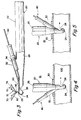
FIG. 1 is a side view of an embodiment of an arterial cannula receiving a modular filter cartridge therein. -
FIG. 2 is a partially cut-away side view of the arterial cannula ofFIG. 1 with the modular filter cartridge received therein, showing the filter partially deployed. -
FIG. 3 is another partially cut-away side view of another preferred embodiment of an arterial cannula with the modular filter cartridge received therein, showing an alternative arrangement of the deployed filter. -
FIGS. 4 and 5 are side views of the distal end of an arterial cannula introduced into a blood vessel, showing the side port located on the back and on the front, respectively, of the cannula. -
FIG. 6 is a perspective view of a distal portion of an arterial cannula from a generally upstream position, showing a conical filter device fully deployed. -
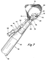
FIG. 7 is a perspective view of the distal end of the arterial cannula ofFIG. 6 from a generally downstream position. -
FIG. 8 is a back view of an embodiment of an expandable filter device in accordance with the present invention. -
FIG. 9 is a side view of the expandable filter device ofFIG. 8 . -
FIG. 10 is a cross-section of a support strut taken along line 10-10 ofFIG. 9 , including an inflation seal for engaging the wall of a vessel when the expandable filter device is deployed. -
FIG. 11 is a cross-section of an alternative embodiment of a support strut taken along line 10-10 ofFIG. 9 , including a self-expanding foam for engaging the wall of a vessel. -
FIGS. 12 and 13 are side views of alternative embodiments of expansion frames for use in an expandable filter device. -
FIG. 14 is a side view of a spring-activated expansion frame for an expandable filter device. -
FIG. 15 is a side view of an embodiment of an expansion frame having "sausage" struts and an inflation seal. -
FIGS. 16 and17 are perspective views of the distal portion of a cannula with modular filter device with the expandable filter device deployed. -
FIG. 18 is a perspective view of a distal portion of an arterial cannula with modular filter device, showing the modular filter cartridge after being received in the arterial cannula. -
FIG. 19 is a perspective view of a distal portion of the arterial cannula with modular filter device ofFIG. 18 , prior to the modular filter cartridge being received in the arterial cannula. -
FIGS. 20A-F are top elevations of an embodiment of an adjustable filter device showing the insertion of the device through a hollow vessel insertion device and into a vessel. -
FIG. 20G is a perspective elevation of the device ofFIG. 20A . -
FIG. 20H is a top elevation of the device ofFIG. 20A . -
FIG. 21A is a top elevation of an embodiment with a slidable cantilever beam and a filter cartridge. -
FIG. 21B is a lateral elevation of the embodiment ofFIG. 21A . -
FIGS. 21C-H show the distal region of the embodiment ofFIG. 21A as the device withdraws into and protrudes out of a filter cartridge. -
FIG. 21I shows a perspective elevation of an exploded view of a detail of the device ofFIG. 21C along line I---I. -
FIG. 21J is a detail of the cantilever beam of the embodiment ofFIG. 21 A . -
FIG. 21K is an end view of the cantilever beam of the device ofFIG. 21J along line K -K. -
FIG. 21L is a cross-section of the embodiment ofFIG 21C along line L--L. -
FIG. 22A shows a top elevation of a center-hinged adjustable filter device. -
FIG. 22B shows the adjustable filter of the device ofFIG. 22A expanded inside the lumen of a vessel. -
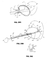
FIG. 23A is a perspective elevation of another embodiment of the adjustable filter frame where the frame sizing mechanism is an adjustable slip joint. -
FIG. 23B is a lateral elevation of the device ofFIG. 23A . -
FIGS. 23C-D show the embodiment ofFIG. 23A where the adjustable frame conforms to the inner lumen of two vessels of different sizes. -
FIG. 24 is another embodiment of a filter device with an adjustable frame where the frame sizing mechanism is a slip joint. -
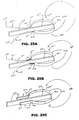
FIGS. 25A-C show various embodiments of a self-adjusting frame suspended from a cantilever beam. -
FIG. 26A shows another embodiment of an adjustable spring cable frame suspended from a cantilever beam. -
FIG. 26B depicts a "coin-purse" type cantilever beam embodiment. -
FIG. 26C shows the embodiment ofFIG. 26B along line C-C upon closure. -
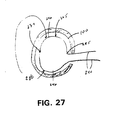
FIG. 27 shows a top elevation of an adjustable frame inside a vessel, where the sizing mechanism is a fixed break point and varying lengths of frame material. -
FIGS. 28A-D show an embodiment of an adjustable frame where the sizing mechanism is a segmented frame. -
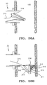
FIG. 29 shows a perspective elevation of an adjustable frame with a stabilizing plate. -
FIG. 29A shows the embodiment ofFIG. 29 , where the stabilizing plate is covered with a protective covering. -
FIG. 30A shows another embodiment of an adjustable frame where the sizing mechanism permits flexion and extension of the frame material. -
FIG. 30B is a detail of the frame ofFIG. 30A . -
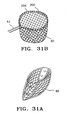
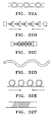
FIG. 31A shows a filter mesh that can be coupled to a filter frame. -
FIG. 31B shows perspective elevation of a filter mesh coupled to a spring coil wound around an adjustable frame. -
FIGS. 32A-F show details of various embodiments of the adjustable frame material. -
FIG. 33A is a top elevation of a five hinge cantilever beam filter device protruding out the end of a filter cartridge. -
FIG. 33B is a lateral elevation of the embodiment ofFIG. 33A . -
FIG. 33C shows the embodiment ofFIG. 33A where the filter device is retracted inside the filter cartridge. -
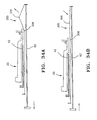
FIGS. 34A-B show the device ofFIG. 33A as it is expanded and contracted by manipulating the arms of the frame. -
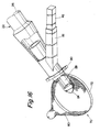
FIG. 35 is a lateral elevation of another embodiment of an adjustable filter device inside a vessel where the filter is deployed at an approximate right angle to the main lumen of the insertion device. -
FIGS. 36A-B show lateral elevations of an adjustable frame filter device deployed inside a vessel, where the frame sizing mechanism allows the frame to collapse as it is retracted inside the insertion device. -
FIG. 36C shows an end elevation of the struts of the frame of the embodiment ofFIG. 36A . -
FIG. 37 shows a lateral elevation of an embodiment of a filter device where the upper portion of the filter is less permeable than the lower portion. -
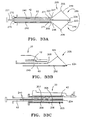
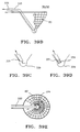
FIG. 38 shows a lateral elevation of an embodiment with a sac coupled to the apex of the filter mesh. -
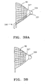
FIG. 39A shows the embodiment ofFIG. 38 where the filter device includes an aspiration tube to remove debris from the sac. -
FIG. 39B shows a partial cutaway of the embodiment ofFIG. 39A . -
FIG. 39C shows a detail of the sac region of an embodiment of a filter device with an aspiration tube. -
FIG. 39D shows a detail of the sac region of an embodiment of a filter device with an aspiration tube that has a turbine at its distal tip. -
FIG. 39E shows a top elevation of an embodiment of a rotating filter with an aspiration tube. -
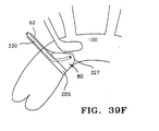
FIG. 39F shows an embodiment of a filter device with an aspiration tube positioned inside the aorta. -
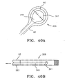
FIG. 40A is a top elevation of an embodiment of a filter device with a scraping device to physically move the debris toward the aspiration tube. -
FIG. 40B is a lateral elevation of the device ofFIG. 40A . -
FIG. 41A is a lateral elevation of an embodiment of a cannula with a filter liner. -
FIGS. 41B-C show the embodiment ofFIG. 42A as the liner compresses into the lumen of the cannula to permit passage of the filter device. -
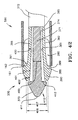
FIG. 42 shows a lateral cross-section of an embodiment of an expanding obturator expanded out of the distal end of an insertion device. -
FIGS. 43A-C show a lateral cross-section of another embodiment of an expandable obturator as it progresses through and out the distal end of an insertion device. -
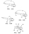
FIGS. 44A-F show an embodiment of an obturator with an indexing/locking mechanism coupled to an introducer. -
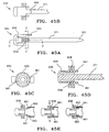
FIGS. 45A-D depict the embodiment of the obturator ofFIG. 44 : -
FIG. 45E shows a progression of the engagement of the indexing/locking mechanism ofFIGS. 44 and45 . -
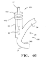
FIG. 46 is an embodiment of a blood filtering system. -
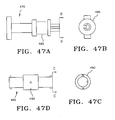
FIGS. 47A-G depicts another embodiment of an indexing/locking mechanism. -
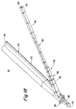
FIG. 48A is a lateral elevation of an embodiment of a vessel sizing tool inserted through an insertion device and into a vessel. -
FIG. 48B is a lateral elevation of an embodiment of a vessel sizing tool that includes a vessel sizing cartridge. -
FIG. 48C is a lateral cross-section of the embodiment ofFIG. 46A . -
FIG. 49A is a lateral elevation of an embodiment of a filter cartridge with a vent hole. -
FIG. 49B is an expanded lateral cross-section of area "B" of the embodiment ofFIG. 49A showing the vent hole. -
FIG. 49C is a cross-section of the embodiment ofFIG. 47B along line C-C. -
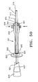
FIG. 50 is a lateral cross-section of the filter cartridge ofFIG. 21 showing an embodiment of a vent hole and an indexing/locking mechanism. - Turning now to the drawings,
FIGS. 1-5 and 16-19 show embodiments of an arterial cannula withmodular filter device 10. As shown inFIGS. 18 and19 , thedevice 10 generally includes three components, namely acannula 20, atubular cartridge 42 and anexpandable filter device 60. The latter two components together defining amodular filter apparatus 40. - The
cannula 20 is an elongatetubular member 22, having a proximal end (not shown), adistal end 24, and alumen 26 which extends between the proximal and distal ends 24. The proximal end is adapted for receiving blood from a bypass-oxygenator machine (not shown). Thedistal end 24 has a tapered, curved and/or rounded end adapted to enter an artery (not shown), and includes anoutlet 28 communicating with thelumen 26. Thecannula 20 may be formed from a substantially rigid material. - The
cannula 20 includes aside port 32 for receiving themodular filter apparatus 40. Theside port 32 may be attached to or integrally formed on thecannula 20, possibly on the front (downstream area), back (upstream area) or side of the cannula, as shown, for example, inFIGS. 4 and 5 . Preferably, theside port 32 is located adjacent thedistal end 24 of thecannula 20 above asuture flange 30 thereon, and extends diagonally from thecannula 20. Apassage 34 extends from theside port 32 to thelumen 26 in thecannula 20, as shown inFIG. 2 . Alternatively, thepassage 34 may communicate with thelumen 26 of thecannula 20, and thedistal end 24 of thecannula 20 may include aseparate filter outlet 29, as shown inFIG. 3 , or thepassage 34 may be isolated from thelumen 26 and extend distally from theside port 32 along a wall of thecannula 20 to a filter outlet (not shown) on or adjacent thedistal end 24 of thecannula 20. Preferably, theside port 32 also has a predetermined cross-sectional configuration corresponding to themodular filter apparatus 40, as explained below. Optionally, theside port 32 may include a hemostatic valve (not shown) across thepassage 34, providing a fluid-tight seal that prevents fluid flow out of thepassage 34 from thelumen 26 of thecannula 20, yet allows themodular filter apparatus 40 to be received in and removed from theside port 32. - The
tubular cartridge 42 is generally an elongate tubular member having aproximal end 44, adistal end 46 and a channel (not shown) for receiving thefilter device 60. Thecartridge 42 facilitates the modular nature of thedevice 10, providing a hemostatic seal between thefilter device 60 and theside port 32 on thecannula 20. Thecartridge 42 may have anouter wall 48 shaped similarly to thepassage 34 in theside port 32 as shown inFIGS. 18 and19 , thereby providing a fluid-tight seal when themodular filter apparatus 40 is received in theside port 32. The channel in thecartridge 42 may also have a shape similar to thefilter device 60 to provide a fluid-tight seal between thecartridge 42 and thefilter device 60. Alternatively, a hemostatic valve (not shown) may be provided across the channel, for example at theproximal end 44 of thecartridge 42 to provide a fluid-tight seal, yet allow thefilter device 60 to be slidably received in and possibly removed from thecartridge 42. Preferably, thecartridge 42 is provided from molded plastic materials that provide a hemostatic seal when theouter wall 48 of thecartridge 42 slidably engages thepassage 34 in theside port 32, and when theshaft 62 of thefilter device 60 slidably engages the channel in thecartridge 42. - Referring to
FIGS. 16-19 , theexpandable filter device 60 generally includes ashaft 62, ahandle 68 and anexpandable filter 70. Theshaft 62 is generally an elongate member, having thehandle 68 on itsproximal end 64 and theexpandable filter 70 on itsdistal end 66. Optionally, theshaft 62 may include apassage 65, such as for an inflation lumen or a mechanical control apparatus for theexpandable filter 70, extending between theproximal end 64 and the distal end (not shown). Theshaft 62 may be provided from a resilient semi-rigid material that is biased to a particular shape, for example to remain substantially straight, but is sufficiently flexible to follow the contour of thepassage 34 and/or thelumen 26 in thecannula 20. Exemplary materials include plastic or metal. Generally, theshaft 62 may have a cross-section corresponding to the channel in thecartridge 42, thereby providing a hemostatic seal that prevents flow of fluid through the channel, although alternatively, thecartridge 42 may include a separate seal as described above, or theshaft 62 may include a seal (not shown). - Preferably, the cross-sections of the
side port 32, thecartridge 42 and theshaft 62 have a substantially square, rectangular, circular, oblong or other similar shape. The corresponding shape or the indexing/locking mechanisms hereinafter described, preferably limit thedevice 10 to being assembled in a single orientation. This may be particularly important to ensure that theexpandable filter 70 is deployed within a blood vessel such that it intersects the vessel, and substantially engages the wall of the vessel to effectively capture embolic material. Theside port 32 also helps orient the surgeon using thedevice 10 with respect to the vessel. For example, with theside port 32 on the side of thecannula 20 as shown inFIGS. 16 and17 , the surgeon may orient theside port 32 perpendicular to the vessel to ensure that the outlet is directed downstream and that the filter is oriented for proper deployment. Alternatively, an indexing/locking mechanism may provide such orientation for circular shaped devices. - Turning now to
FIGS. 8 and 9 , an embodiment of anexpandable filter 70 is shown that may be provided on or near thedistal end 66 of theshaft 62. Theexpandable filter 70 generally includes anexpansion frame 72 capable of assuming enlarged and contracted conditions, andfilter mesh 80. Preferably, theexpansion frame 72 includes a plurality ofstruts 74 that may be expanded and contracted to define respectively the enlarged and contracted conditions.Filter mesh 80 is attached to thestruts expansion frame 72. For a complete explanation of the design and construction of a filter mesh for use herein, the reader is referred toBarbut et al., U.S. Application Serial No. 08/553,137, filed November 7, 1995 Barbut et al., U.S. Application Serial No. 08/580,223, filed December 28, 1995 Barbut et al., U.S. Application Serial No. 08/584,759, filed January 9, 1996 Barbut et al., U.S. Application Serial No. 08/640,015, filed April 30, 1996 Barbut et al., U.S. Application Serial No. 08/645,762, filed May 14, 1996 - In the preferred embodiment of
FIGS. 8 and 9 , thestruts Stabilizers 76 may be provided to stabilize theexpansion frame 72, or may be omitted if the bias of thestruts struts shaft 62 using hinged joints to facilitate expanding and contracting theexpansion frame 72. - The open end struts 75 may also include seals for engaging the wall of a blood vessel to substantially minimize embolic material traveling around the periphery of the deployed
expandable filter 70. For example, as shown inFIG. 10 , thestruts 75 may include a silicone orurethane balloon 76 attached along their length that may be inflated from a lumen (not shown) extending between thestruts 75 and theshaft 62. Theballoon 76 may also be used to expand theexpansion frame 72 to its enlarged condition if thestruts FIG. 11 , thestruts 75 may include a self-expandingfoam 82, such as silicone, that will expand when theexpandable filter 70 is deployed to substantially engage the wall of the vessel. - Alternatively, as shown in
FIG. 3 , thestruts 74 may have an umbrella-like configuration, which may be particularly useful when theexpandable filter 70 is deployed out afilter outlet 29 on the back (upstream side) of thecannula 20. Thestruts 74 may be biased to expand to the enlarged condition. To remove theexpandable filter 70, theshaft 62 may be pulled proximally, closing thestruts 74 as they enter thefilter outlet 29. - In another preferred embodiment, such as that shown in
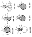
FIGS. 6 and7 , theexpansion frame 72 is a self-expandingring 73 formed from spring stainless steel or a superelastic and/or shape memory material, such as Nitinol. Thering 73 may be compressed for insertion into thecartridge 42, but, because of the shape memory of the material, it is biased to open automatically into an annular shape when theexpandable filter 70 is deployed. Preferably, thering 73 also includes akink 75 adjacent thedistal end 66 of theshaft 62 to bias thering 73 against the wall of the vessel, and maximize the cross-section of the vessel intersected by theexpandable filter 70. Without thekink 75; the ring may deform slightly, creating an imperfect circular cross-section that may allow embolic material to escape around the periphery of the deployedexpandable filter 70. Thefilter mesh 80 attached to thering 75 preferably has a substantially conical shape, such that when thering 75 expands across the vessel, themesh 80 is pulled open downstream by blood flow in the vessel to capture any embolic material traveling through the vessel. - Alternatively, as shown in
FIG. 15 , theexpansion frame 72 may include aring 75 having a "sausage" configuration, that is, having hinges or dimples on several locations around thering 75, allowing thering 75 to enlarge and contract more easily, and conform tightly to vessel lumen topography. Preferably, this embodiment also includes aballoon 84 attached around the periphery of thering 75 to guide thering 75 to assume a substantially round configuration when theballoon 82 is inflated. - In still another preferred embodiment, a mechanically-operated
expansion frame 72 may be provided. For example, theexpansion frame 72 ofFIGS. 12 and 13 includes aring 78 to which oneend struts ring 78 may be slidable axially in relation to theshaft 62, for example by use of a control wire or sleeve (not shown) to expand and contract thestruts ring 78 may be twisted radially to open and/or close thestruts - As shown in
FIG. 14 , aspring 79 may be provided between theends struts spring 79 may be compressed by use of a control wire or like apparatus (not shown) to expand thestruts filter 70 is to be removed, thespring 79 biases theexpansion frame 72 to compress thestruts mesh 80. - Alternatively, the open end struts 75 may themselves be provided from compressed springs (not shown), thus biasing them to the contracted condition. Such struts may conform more easily to the shape of the wall of the vessel than solid struts.
- Generally, as shown in
FIG. 19 , thecannula 20 and themodular filter device 40 are furnished separately, although alternatively, thedevice 10 may be provided preassembled as inFIG. 18 . Thecartridge 42 andfilter device 60, however, are generally preassembled, thereby providing themodular filter cartridge 40. This is accomplished by compressing the expandable filter (not shown) and directing the distal end (not shown) of theshaft 62 into the channel (not shown) in thecartridge 42, such that the expansion frame and mesh (not shown) are substantially contained within thecartridge 42. - Prior to use, the
modular filter cartridge 40 may be inserted into theside port 32 of thecannula 20, as shown inFIG. 18 . Thedistal end 24 of thecannula 20 may then be introduced into ablood vessel 100, such as the aorta, using conventional procedures, as illustrated inFIGS. 4 and 5 , allowing blood to be carried into thevessel 100 from thelumen 26. Once thedistal end 24 of thecannula 20 is in position within thevessel 100 and thecannula 20 is secured to the patient, such as using thesuture flange 30, the expandable filter may be deployed into the vessel, as shown inFIGS. 16 and17 . - As shown in
FIGS. 2 and3 , theshaft 62 of thefilter device 60 may be directed distally to deploy theexpandable filter 70 on itsdistal end 66. This causes theexpandable filter 70 to pass through thepassage 34, through thelumen 26 in thecannula 20 and to exit thedistal end 24 of thecannula 20 either through the outlet 28 (FIG. 2 ) or the filter outlet 29 (FIG. 3 ), into the vessel (not shown inFIGS. 2 and3 ). Theexpansion frame 72 may open automatically, or may be mechanically expanded to its enlarged condition, thereby opening thefilter mesh 80 substantially across the vessel and capturing any embolic material traveling therethrough. At any time, theexpansion frame 72 may be closed to its contracted condition, entrapping any embolic material captured by themesh 80, and theexpandable filter 70 withdrawn by pulling proximally on theshaft 62. Theexpandable filter 70 may be returned into thecartridge 42, which may then be removed from theside port 32. A newmodular filter cartridge 40 may be inserted into theside port 32 at any time thereafter, allowing a newexpandable filter 70 to be introduced into the vessel, as desired during a surgical procedure. - The modular filter devices and delivery systems described are particularly useful in cardiac surgery. A cannula with modular filter as described above may be deployed within the aorta, for example, upstream of the carotid arteries. The aorta may be clamped upstream of the cannula with modular filter in preparation for a bypass procedure. This clamping generally substantially increases the risk of embolic deposits breaking loose from the wall of the aorta and traveling downstream. With the filter deployed, however, embolic material dislodged during this action may be captured by the filter device. Once the aorta is clamped, the risk of further embolic material being dislodged may be substantially reduced, and so the filter may be removed without substantial concern about embolic material escaping and possibly injuring the patient.
- Later in the surgery, a new filter device may be introduced through the cannula into the aorta prior to any action which may substantially increase the risk of further embolic material breaking loose, such as when the aorta is unclamped. Because a new filter may be deployed, any embolic material that is dislodged may be captured more effectively, as opposed to a filter which must remain in the aorta throughout the procedure which may become clogged and impair blood flow through the vessel.
- Similarly, the cannula with modular filter may be used to capture embolic material when balloon occlusion is used instead of clamping to close the aorta in bypass procedures. In this procedure, the occlusion balloon may be provided on the same cannula providing the modular filter. Alternatively, a catheter may be introduced into the aorta upstream of the bypass cannula, possibly through a cardioplegic cannula. A filter may be deployed prior to inflation of the occlusion balloon, thereby capturing any embolic material released by the balloon as it engages the walls of the aorta. This procedure may be slightly disfavored, however, since it may reduce the work space available for the bypass cannula and modular filter device.
- An important feature is that the filter may be placed immediately downstream of the location which is likely to generate emboli within the bloodstream, such as within the aorta. In addition, a filter device in accordance with the present may more effectively capture embolic material, because the expansion frame in the enlarged substantially engages the wall of the vessel extending the mesh across the vessel, and because the expansion frame may be closed before removal, entrapping the captured material. Thus, the arterial cannula with modular filter device may more effectively capture and remove embolic material released during extended procedures, such as coronary bypass surgery, without clogging the filter and impairing blood flow through the vessel.
- In some cases, it may desirable to provide the filter upstream of the cannula outlet through a separate filter outlet, as shown in
FIG. 3 . For example, this embodiment eliminates filtering the bypass blood which may accelerate clogging of the filter. It also may allow a variety of nozzle designs to be provided on the cannula, without concern that the outlet may be partially obstructed by the shaft of the filter device, as may occur with filters deployed through the cannula outlet. - Certain embodiments of the modular filter apparatus are directed to devices that include adjustable filter frames, where the frame is either self-adjusting, as previously described, or can be adjusted manually by operating a mechanism outside the vessel. Some of these embodiments are depicted in
FIGS. 20-37 . -
FIGS. 20A-H depict an embodiment of amodular filter apparatus 200 for insertion into a hollowvessel insertion device 580 for filtering embolic material from ablood vessel 100 into which the insertion device is introduced. Theinsertion device 580 is an elongated tube having anouter surface 581, adistal end 582, adapted to enter an artery, aproximal end 583 and alumen 584 therebetween. The embodiment ofFIG. 20 also includes a flange 585 disposed about the distal region. In some embodiments, the hollow vessel insertion device is a cannula, as previously described. In other embodiments, the insertion device is an introducer, hereinafter described. The filter apparatus includes ashaft 62 having aproximal end 221 and adistal end 220. Anadjustable filter frame 205 is disposed about thedistal end 220 of theshaft 62, and theframe 205 is adjustable between a contracted condition and an enlarged condition. The particular embodiment ofFIGS. 20A-H can be externally adjusted. Theframe 205 has adiameter 230 and aninterior area 232, and aframe sizing mechanism 210 associated with the frame. In the case of this embodiment, the frame sizing mechanism includes acenter hinge 234, which in this depiction is a thinner section of frame material, together with aproximal region 238 that includes two thin frame areas and twoframe arms 240 that protrude out of the vessel and may be externally manipulated to cause the frame to enlarge and contract to fit the vessel size. In certain embodiments, the frame and mesh coupled thereto are demountable from the shaft. The embodiment ofFIGS. 20A-H also includes anexpandable sheet 245 coupled to a portion of the proximal region of theframe 238. The sheet stretches and contracts as the frame is enlarged or contracted. The apparatus also includes afilter mesh 80 coupled to the frame for capturing embolic material. The modular filter apparatus is removably insertable into a hollowvessel insertion device 580, and upon insertion through the device and into thevessel 100, the frame sizing mechanism is operated to adjust the diameter of the filter frame to conform to the inner lumen of the vessel. -
FIGS. 20A-F show the insertion of the filter apparatus into theinsertion device 580. First theframe 205 is pinched along thesides 231, as shown inFIG. 20B , until thecenter hinge 234 buckles forming a point as shown inFIG. 20C . Theframe 205 is then inserted into theinsertion device 580, as shown inFIG. 20D . When theproximal region 238 of the frame has cleared the insertion device and has entered the vessel, the frame enlarges as shown inFIG. 20E . If the frame diameter has not conformed to the vessel size, as shown inFIG. 20E , and needs to enlarge, thearms 240 of the frame may be externally manipulated by pushing them into the insertion device. As shown inFIG. 20F , the frame then further enlarges and theexpandable sheet 245 in theproximal region 238 stretches as the frame fully conforms to the vessel size. Conversely, if the frame were too large, thearms 240 of the frame could be pulled thus contracting the frame size to fit the vessel. -
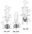
FIGS. 21A-L show an embodiment of a modular filter apparatus that also includes atubular cartridge 42 for receiving the distal end of thefilter shaft 62 and protecting theadjustable frame 205 andmesh 80. The cartridge is removably insertable into an insertion device (not shown). In certain embodiments, thetubular cartridge 42 provides a hemostatic seal or one-way valve between thefilter shaft 62 and the insertion device into which the cartridge may be inserted. In some embodiments, the cross-section of theshaft 62 is non-round and the lumen in thecartridge 42 conforms to the shape of theshaft 62, as shown inFIG. 21L . Such a configuration inhibits rotation of the shaft in the cartridge thereby fixing alignment of the frame in an orientation determinable from the orientation of the cartridge. The embodiments shown inFIGS. 21A and B also include adistal region 460 that can include an indexing or indexing/locking mechanism as hereinafter described in more detail. - Certain embodiments of the modular filter apparatus, as depicted in
FIGS. 21 ,25 ,26 ,33 and34 , include a cantilever beam configuration to help stabilize the filter frame and, in some cases, to assist in frame sizing. As shown inFIGS. 21 A-L , these devices have aframe 205 with aproximal region 238, adistal region 239 and acantilever beam 250 that has aproximal end 252, adistal end 253 and across-section 254. Thedistal end 253 of thebeam 250 is associated with thedistal region 239 of theframe 205, and theproximal end 252 of the beam is associated with thedistal end 220 of thefilter shaft 62. In certain embodiments of the cantilever beam configuration, as shown inFIGS. 25A-C and FIG. 26A , the proximal end of the beam is continuous with the distal end of the shaft. However, in the embodiment ofFIGS. 21A-L , theproximal end 252 of the beam is not continuous with thedistal end 220 of theshaft 62. In some embodiments, the proximal region of the frame is associated with the distal end of the shaft, and in other embodiments, the proximal region of the frame is associated with the proximal end of the beam. In the embodiment ofFIGS. 21A-L , theproximal region 238 of the frame is coupled to thedistal end 220 of theshaft 62, and thedistal end 253 of the beam is coupled to thedistal region 239 of the frame. In certain embodiments, the proximal end of the cantilever beam is coupled to the distal end of the filter shaft. In other embodiments, such as depicted inFIGS. 21A-L , thefilter shaft 62 has alumen 223 that extends from the proximal end of the shaft (not shown) to anopening 224 in the distal end of the shaft. Theproximal end 252 of thecantilever beam 250 is slidably insertable into thedistal opening 224 of theshaft 62. The slidablyinsertable cantilever beam 250 is also part of the frame sizing mechanism. - The embodiment of
FIGS. 21A-L also has a frame anti-rotating mechanism to help stabilize the orientation of the frame relative to the shaft and thus inhibit rocking of the frame or frame migration along the vessel. In one embodiment, as shown inFIGS. 21I - 21 K , thecross-section 254 of thecantilever beam 250 is non-round, in this case oval, and theopening 224 in the distal end of the filter shaft is of a shape that conforms to the shape of thecross-section 254 of the cantilever beam. In other embodiments, the cantilever beam cross-section may be other shapes such as rectangular, triangular or the like. The embodiment ofFIG. 21I also has ashelf 225 on thedistal end 220 of the shaft to support theproximal region 238 of the frame to further inhibit rotation of the frame on the shaft. During use, the shape of theopening 224 in the distal end of thefilter shaft 62, the shape of thecross-section 254 of thebeam 250, and in the case of the embodiment ofFIG. 21I , theshelf 225 all inhibit rotation of thebeam 250 in thelumen 223 of the shaft and thus inhibit the frame from rotating as it resides in the vessel. - The sequence of
FIGS. 21C - 21H shows how themodular filter apparatus 200 can be withdrawn into thetubular cartridge 42 and how theslidable cantilever beam 250 assists in sizing the frame to the vessel.FIG. 21C shows theframe 205 in its fully enlarged condition. InFIG. 21D , pressure has been applied to thedistal region 239 of the frame, and thebeam 250 has started to slide into thelumen 223 of theshaft 62. InFIG. 21E , the proximal end of theshaft 221 has been pulled and themodular filter apparatus 200 has been withdrawn into thefilter cartridge 42.FIG. 21H shows how theframe 205 may adjust to fit a smaller vessel by slidable insertion of thebeam 250 into thelumen 223 of theshaft 62. Thesegments 246 of the frame on either side of the beam rock upward creating a smaller frame profile capable of fitting a smaller vessel. - In some embodiments, as shown in
FIGS. 25A-C and FIG. 26A , the proximal end of the beam is continuous with the distal end of the shaft. These embodiments include aframe 205 with anopen loop 286 with twoends length 249 between the ends. The frame also includes twoarms proximal end 270 and adistal end 271. The distal ends 271, 271 of eacharm end frame 205. Thedistal end 253 of thebeam 250 is coupled to the approximate middle of thelength 249 of theloop 286 in a cantilever beam configuration with thearms shaft 62. During use, thearms loop 286 of theframe 205 to fit the vessel in which the frame resides. In some embodiments, such as the depiction inFIG. 25C , thearms length 249 between theends loop 286. In these embodiments, the relative rigidity of the arms lends support as the arms are pushed or pulled to adjust the size of theloop portion 286 of the frame. In other embodiments, such as the depiction inFIG. 25B , the distal ends 271, 271 of thearms loop portion 286 of the frame which allows a more circular configuration of theloop portion 286 as the arms are pushed pulled to adjust the frame to the vessel.FIG. 26A shows an embodiment where theentire loop portion 286 and the distal portion of thearms ring 275 that slidably receives theshaft 62 and thearms ring 275 helps to hold the arms closer to the sides of the shaft for greater control when the arms are pushed or pulled to adjust the size of the frame. In still other embodiments, such as the depiction infigure 25A , thearms - Another embodiment with a type of cantilever configuration is depicted in
FIG. 26B-C . Theframe 205 of this embodiment hasopen loop 286 with anend length 249 between the ends Theloop portion 286 of the frame has aproximal region 238 and adistal region 239, adiameter 230 running from theproximal region 238 to thedistal region 239, aright segment 277 and aleft segment 278 on either side of thediameter 230. Theframe 205 also has twoarms proximal end distal end distal end end loop portion 286 of the frame. Thearms diameter 230 of the loop portion in a cantilever beam configuration. Thefilter shaft 62 has a distal region 279 pivotally coupled to theproximal region 238 of the loop portion of the frame. The shaft also has alumen 223 which extends from anopening 280 in theproximal end 221 to an opening (not shown) in thedistal end 220. Thedistal end 220 opening is adapted to slidably receive the proximal ends 270, 270 of thefilter arms filter arms distal end 220 of thefilter shaft 62, through thelumen 223 of theshaft 62 and out theopening 280 in the shaftproximal end 221. During use, the proximal ends 270, 270 of thearms filter frame 205 are adjusted by pulling the ends proximally or pushing them distally causing thediameter 230 of theloop 286 to shorten or lengthen and causing eachsegment shaft 62 to adjust to the size of the vessel in which the frame resides.FIG. 26C is an end view of the embodiment ofFIG. 26B along line C-C, showing the effect of pulling on thearms 240, causing the right and leftsegments frame 205 to pivot radially toward one another in a coin-purse closure action. - Other loop frames that are not cantilever configurations are also described. The embodiment of
FIG. 22A-B is a loop frame where theloop 286 has afirst end 247 and asecond end 248 andlength 249 between the two ends. As described previously, theshaft 62 has a lumen (not shown) which extends from an opening in the proximal end (not shown) to an opening in thedistal end 224 that is adapted to slidably receive the two ends 247, 248 of theloop frame 205. Both ends 247, 248 of the loop frame are slidably insertable into theopening 224 in the distal end of thefilter shaft 62, through the lumen of the shaft and out the opening in the proximal end (not shown). During use, the ends of the filter frame are adjusted by pulling them proximally or pushing them distally causing the frame to adjust to the size of the vessel in which the frame resides. - The embodiment of
FIGS. 22A-B also includes acenter hinge 234 in the approximate middle of thelength 249 of theloop 286, thus dividing the frame length into twosegments frame segment center hinge 234 as the frame ends 247, 248 are pushed or pulled causing theframe 205 to adjust to the size of the vessel in which the frame resides.FIG. 22B shows theloop frame 205 ofFIG. 22A , as viewed along axis line B--B, fully enlarged in avessel 100. -
FIG. 27 is also an embodiment of a loop frame with acenter hinge 234 in theframe 205. This embodiment also has akink 285 in the frame in a position where one of thearms loop 286 portion of the frame. The sizing mechanism includes thekink 285, thehinge 234 and thearms segments hinge 234 to rotate. - Certain embodiments of the modular filter apparatus include various types of slip joints, some self-adjusting and others that are externally adjustable.
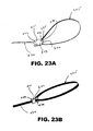
FIGS. 23A-D depicts an embodiment of an externally adjustable slip-joint filter frame. The apparatus includes afilter frame 205 that has a fixedend 235 and anadjustable end 236 and a sizing mechanism that includes a slip joint 241, having aproximal end 242 and adistal end 243 and a lumen (not shown) that extends from an opening in theproximal end 244 to an opening in the distal end (not shown). The slip joint 241 is associated with the filter shaft (not shown). Thedistal end 243 of the slip joint 241 is pivotally coupled 233 to the fixed end of theframe 235. Thedistal opening 244 of the slip joint 241 is adapted to slidably receive theadjustable end 236 of the frame, which slidably inserts through theopening 244 and is advanced along the shaft of the filter (not shown). During use, theadjustable end 236 of the frame is manually pushed distally or pulled proximally causing the frame to slide into or out of the slip joint 241 and adjust to the size of the inner lumen of the vessel in which the frame resides.FIGS. 23C and 23D show the embodiment of the adjustable slip-joint frame ofFIG. 23A invessels 100 that are of two different diameters. - In other embodiments of the modular filter apparatus, the slip joint is self-adjusting.
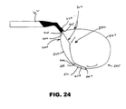
FIG. 24 depicts a self-adjusting modular filter apparatus that includes afilter frame 205 that has a fixedportion 260 and a variable portion 264. The fixedportion 260 has afirst end 261 coupled to the distal end of thefilter shaft 62, asecond end 262 and a first length 263. The variable portion 264 has afirst end 265 coupled to the distal end of the shaft, a second end 266 and a second length 267. The second length 267, which is the length of the variable portion is greater than the first length 263, which is the length of the fixed portion. The sizing mechanism further includes a slip joint 241, that has afirst end 269, a second end 267 and a lumen 268 that extends from an opening (not shown) in thefirst end 269 to an opening (not shown) in the second end 267. Thefirst end 269 of the slip joint is coupled to thesecond end 262 of the fixed portion 263 of the frame. The second end 267 of the slip joint 241 is adapted to slidably receive the second end 266 of the variable portion 264 of theframe 205. The second end 266 of the variable portion 264 is slidably inserted into the opening in the second end 267 of the slip joint 241, through the lumen 268 of the slip joint 241 and out the opening in thefirst end 269 of the slip joint and is coupled to thedistal end 220 of theshaft 62. During use, the variable portion 264 of theframe 205 contracts by sliding into the slip joint 241 and thus buckling into theinterior area 232 of the frame or enlarges by sliding out of the slip joint 241 to self-adjust to the size of the inner lumen of the vessel in which the frame resides. -
FIGS. 28A-D depict an embodiment of amodular filter apparatus 200 that includes a segmented tubular frame that acts as a frame sizing mechanism for external adjustment of the frame. Theframe 205 includes afirst segment 291 and asecond segment 290, each segment having a relatively straightproximal end 292, an approximately semicirculardistal end 293 and a lumen (not shown) that extends from anopening 295 in eachproximal end 292 to anopening 296 in each distal end. The apparatus also includes a mesh 80 (not shown inFIGS. 28A and B .) Each segment is oriented so that the straight proximal ends 292 are aligned together and the distal ends 293 curve away from one another forming an approximate circle. Theframe 205 also includes awire 297, as shown inFIG. 28B , slidably inserted into theopening 295 in theproximal end 292 of thefirst segment 291, out an opening (not shown) in the distal end of thefirst segment 291, into anopening 296 in the distal end of thesecond segment 290 and out anopening 295 in the proximal end of thesecond segment 290. During use, the ends of thewire proximal openings segments segments FIG. 28C shows how the twosemicircular ends segments FIG. 28C also shows themesh 80 attached to the segments.FIG. 28D is a top elevation of the embodiment ofFIG. 28C showing how themesh 80 will fold back on itself as the twosegments FIG. 28A shows the twosegments FIG. 28B shows the effect of externally operating thewires 297 to adjust the segments to their desired positions. -
FIG. 29 depicts an embodiment of aloop frame 205 that includes a flat stabilizingplate 300 located in the approximate middle of theloop 286. The plane of the plate is oriented orthogonal to the plane of the frameinterior area 232. During use, the stabilizingplate 300 anchors theframe 205 against the inner wall of the vessel in which the frame resides and inhibits frame rocking or migration along the vessel as theframe arms FIG. 29A further includes a compliantprotective covering 302 over the stabilizing plate. -
FIG. 30A shows yet another embodiment of aloop frame 205 that has a series ofkinks 285 in the frame to enhance flexibility in sizing the frame to the vessel.FIG. 30B is a detail of area B ofFIG. 30A .FIG. 31A shows an embodiment of amesh 80 that may be coupled to a filter frame (not shown). The filter mesh pore size ideally ranges from 40-120µ, but other sizes may be used depending upon the clinical need. The mesh may be plastic fibrous, metal, polyester, nylon, Teflon, or the like, and may be worn, stamped, etched, laser-machined, molded, spun or layered.FIG. 31B shows another embodiment of amesh 80 coupled to aspring coil 700 that is wound over aframe 205. The spring coil evenly spaces the mesh over frames of different sizes.FIGS. 32A-F show various embodiments of frame material that may be used in producing the filter frame. -
FIGS. 33A-C and 34A-B show an embodiment of a five hinge loop frame in a cantilever beam configuration where thebeam 250 is continuous with theshaft 62. Theframe 205 includes anopen loop 286 withends length 249 between theends hinge 234 in the approximate middle of thelength 249 of theloop 286. There are twoadditional hinges center hinge 234 and anend loop 286. The frame further includes twoarms proximal end 270 and adistal end 271. Eachdistal end end open loop 286. Thedistal end 220 of thebeam 250 is coupled to thecenter hinge 234 of the loop in a cantilever beam configuration. Thearms frame 205 lie along theshaft 62 which is continuous with thebeam 250. During use, thearms loop 286 of theframe 205 to fit the vessel in which the frame resides. The apparatus also includes a mesh (not shown).FIG. 33B is a lateral elevation of the embodiment ofFIG. 33A , further depicting acannula 20 and aframe cartridge 42, which are also shown inFIG. 33C. FIG. 33C shows the effect of withdrawing themodular filter frame 205 into thecartridge 42.FIG. 34A shows the effect of pulling on theshaft 62 which causes the side hinges 306, 308 to flex and the frame to decrease in diameter. (The other hinges are not shown.)FIG. 34B shows the effect of pushing on theshaft 62 which causes thehinges - Other embodiments of the modular filter apparatus include basket-type filter configurations as depicted in
FIGS. 35 and 36A-C .FIG. 35A depicts an embodiment of amodular filter apparatus 200 that includes a plurality of triangular-shapedfilter mesh segments 310, each segment having an apex 311, abase 312, twosides mesh 80. Theapices 311 of each segment are coupled together and eachside 313 of asegment 310 is coupled to aside 314 of anadjacent segment 310 to form a conical configuration adjustable between a collapsed configuration, where the bases are drawn together (not shown), and an enlarged condition, as depicted inFIG. 35 , where thebases 312 are flared apart. The filter also includes a plurality ofwires 315, each having aproximal end 316 and adistal end 317. Eachdistal end 317 is coupled to thebase 312 of asegment 310. Theshaft 62 includes alumen 223 that extends from an opening in theproximal end 221 to an opening in thedistal end 220 and a curveddistal region 320. The opening in thedistal end 220 is adapted to slidably receive thefilter frame 205 in a collapsed condition. Theproximal end 316 of each wire is slidably inserted into the opening in thedistal end 220 of theshaft 62, through thelumen 223 and out the opening in theproximal end 221 of the shaft. During use, the proximal ends 316 of the wires are pushed distally or pulled proximally to enlarge or contract thefilter segments 310 to adjust to the size of thevessel 100 in which the filter resides. -
FIGS. 36A-C show another embodiment of the basket configuration of a modular filter apparatus. The filter includes a plurality of triangular-shapedfilter mesh segments 310, each segment coupled to astrut 319 that has an apex 311, a base 312 that has ahole 318 in it, and twosides apices 311 are coupled together and eachside adjacent mesh segment 310 to form a conical configuration adjustable between a collapsed configuration, as depicted inFIG. 36A where the bases of the struts are drawn together and an enlarged condition, as depicted inFIG. 36B , where the bases are flared apart. The filter also includes awire 315 that passes through thehole 318 in each strut. The shaft (not shown) further includes a lumen (not shown) that extends from an opening in the proximal end to an opening in the distal end. The distal opening is adapted to slidably receive the filter in a collapsed condition. Each end of the wire is slidably inserted into the distal region of the shaft, through the lumen of the shaft and out the proximal end. During use, the ends of the wire are pushed distally or pulled proximally to enlarge or contract the mesh segments in order to insert or remove the filter apparatus and also to adjust the apparatus to the size of the vessel in which the filter resides.FIG. 36C depicts an end view of thestruts 319 as viewed from theapices 311 of the struts. - In certain embodiments, various portions of the mesh are occluded to guide the trapped embolic material to a predetermined region of the filter for easier removal. Occlusion techniques include reducing the mesh pore size, and thereby the permeability of the mesh, or coating or covering the mesh with a less permeable material.
FIG. 37 depicts an embodiment of a mesh that has a generally elongated conical shape with an occluded portion. Themesh 80 has aproximal region 325 and adistal region 326 having an apex 327. The mesh in theproximal region 325 is occluded, causing the mesh in that region to divert blood to the distal morepermeable region 326 thereby forcing embolic debris to become trapped in the apex 327 of the mesh. - In other embodiments the mesh of the apex is occluded to enhance trapping the embolic debris.
FIG. 38 depicts an embodiment where the mesh is generally conical in shape and has an inner surface (not shown) and an apex 327. The apex 327 is coupled to a mesh-occludedsac 329 that has an inner surface (not shown). During use, embolic debris is trapped in thesac 329 for later removal. - Embolic debris can be removed in a number of ways. In some embodiments, the embolic debris is captured in the filter and removed when the filter is removed from the vessel. In other embodiments, a device is inserted into the filter while it is in position in the vessel and the embolic debris is removed through the device.
FIGS. 39A-F depict a method of aspirating debris from a filter. The modular filter apparatus includes a filter of the embodiment ofFIG. 38 with a meshoccluded sac 329 coupled to the apex 327 of themesh 80. The apparatus further includes anelongated aspiration tube 330 that has aproximal end 332, adistal end 331 and alumen 333 extending from an opening in theproximal end 332 to an opening (not shown) in thedistal end 331. Theproximal end 332 is adapted to connect to an aspiration source (not shown), and thedistal end 331 is insertable into thesac 329 or the apex of thefilter mesh 80. During use, embolic debris is trapped in thesac 329 ofFIG. 38 or the apex ofFIG. 37 and is drawn into theaspiration tube 330 and removed from the filter when negative pressure is applied to theproximal end 332 of the tube.FIG. 39C is a detail view of thesac 329 area showing the direction of flow of the embolic debris out of thesac 329 and into the aspiration tubedistal end 331.FIG. 39D shows aturbine 335 coupled to thedistal end 331 of the aspiration tube to draw out embolic debris from thesac 329.FIG. 39E is a top elevation of an embodiment where the mesh is rotated as shown by the arrow to pull embolic debris into thesac 329 to facilitate its withdrawal into theaspiration tube 330.FIG. 39F shows an embodiment of thefilter mesh 80 coupled to aframe 205 and the apparatus placed in avessel 100 to capture embolic debris. Theaspiration tube 330 is shown inserted through a lumen in thefilter shaft 62 and into the apex 327 of themesh 80 to remove debris. Thevessel 100 ofFIG. 39F is the aorta, although the device is adapted to insert in other vessels as well. - The embodiment of
FIGS. 40A-B includes anelongated scraping device 340 that has adistal end 341 adapted to scrape embolic debris from themesh 80 toward the distal end of the aspiration tube (not shown), and a proximal end (not shown) adapted to be operated outside the vessel. During use, the proximal end of thescraping device 340 is operated to cause thedistal end 341 to scrape embolic debris trapped in a sac or mesh apex toward the distal end of an aspiration tube (not shown) where it can be drawn into the tube and removed from thefilter mesh 80. - A method of temporarily filtering and aspirating embolic material from the blood in a blood vessel is also described. The method includes the steps of first providing an insertion device which can be a cannula or introducer or the like, where the insertion device has a distal end adapted to enter an artery and a proximal end adapted to receive a modular filter apparatus. A modular filter apparatus is also provided that has an adjustable filter frame capable of assuming enlarged or contracted conditions, a shaft having a proximal end, a distal end, and a lumen which extends from an opening in the proximal end to an opening in the distal end, and a filter mesh therein having an inner surface. An elongated aspiration tube is provided that has a proximal end, a distal end and a lumen extending from an opening in the proximal end to an opening in the distal end. The proximal end of the tube is adapted to connect to an aspiration source and the distal end is slidably insertable into the proximal end of the filter shaft. The distal end of the insertion device is introduced into a blood vessel. The modular filter apparatus is introduced into the port on the insertion device and is subsequently advanced through the insertion device into the blood vessel. The adjustable filter is then deployed in the vessel. The aspiration tube is slidably inserted through the shaft of the filter until the distal end of the tube lies near the inner surface of the filter mesh. Negative pressure is applied to the proximal end of the aspiration tube and embolic debris is drawn away from the inner surface of the mesh and into the tube. The aspiration tube is then removed from the vessel, embolic debris that was generated having already been removed before the aspiration tube is removed from the shaft. Some embodiments of the method just described include the additional step of re-inserting the aspiration tube into the filter shaft near the inner surface of the mesh after the step of removing the tube from the vessel and repeating the step of aspiration.
- The embodiments of the modular filter apparatus described herein are slidably insertable into an arterial cannula. An embodiment of an arterial cannula capable of receiving a modular filter apparatus for capturing embolic material in a blood vessel is depicted in
FIGS. 41A-C . Thecannula 20 includes anouter surface 360, aninner surface 361, a curveddistal end 24 adapted to enter an artery, a proximal end (not shown) adapted to receive blood from a bypass oxygenator machine, alumen 26 which extends from the proximal end to an outlet on the distal end and anopening 150 in a region where the distal end of the cannula curves. Thecannula 20 ofFIGS. 41 A-C also includes aport 32 on theouter surface 360 of the cannula for receiving a modular filter apparatus. The port has a proximal opening (not shown) and apassage 34 extending distally from the proximal opening along the cannula to theopening 150 in the distal curved region of the cannula. - Certain embodiments, such as the one shown in
FIGS. 41A-C , also include a flexible, bloodimpermeable cannula liner 155 adapted to conform to theinner surface 361 of thecannula 20 and cover theopening 150 in the distalcurved region 24 of the cannula when the cannula is free of the modular filter apparatus. During use, theliner 155 compresses away from theopening 150 in the distalcurved region 24 of the cannula as theframe 205 and mesh 80 of the modular filter apparatus are inserted through theport 32 to allow passage of the filter apparatus, but not blood, out theopening 150 in the distalcurved region 24 of thecannula 20.FIG. 41A shows thecannula 20 with theliner 155 in position when the cannula is free of the modular filter apparatus.FIG. 41B shows the modular filter apparatus advancing through theopening 150 in the distal region of the cannula and theliner 155 compressing away from theinner surface 361 of the cannula into thelumen 26 of the cannula.FIG. 41C shows themodular mesh 80 of the modular filter apparatus completely advanced through theopening 150 in the cannula and theliner 155 protecting the integrity of thelumen 26 of the cannula thus inhibiting the flow of blood out theopening 150. - Blood filtering system are also described, and an embodiment is depicted in
FIG. 46 . Thesystem 450 includes anarterial cannula 20 capable of receiving amodular filter apparatus 200 for capturing embolic material in a blood vessel. Thearterial cannula 20 has anouter surface 360, adistal end 24 adapted to enter an artery, a proximal end (not shown) adapted to receive blood from a bypass oxygenator machine, and alumen 34 which extends from the proximal end to the distal end, and aport 32 for receiving themodular filter apparatus 200. Thesystem 450 also includes amodular filter apparatus 200 for insertion into theport 32 of thearterial cannula 20. The filter apparatus includes (as shown in previous figures) a shaft having a proximal end and a distal end, an adjustable frame disposed about the distal end of the shaft, which is expandable between a contracted condition and an enlarged condition, a frame sizing mechanism associated with the frame, and afilter mesh 80 coupled to the frame for capturing embolic material. Themodular filter apparatus 200 is removably insertable into thearterial cannula 20, and, upon insertion through the cannula into the artery the frame sizing mechanism adjusts the diameter of the filter frame to conform to the inner lumen of the vessel. The embodiment ofFIG. 45 also includes afilter cartridge 42 having adistal region 460.FIG. 45 also shows aproximal region 470 on thecannula port 32. - Certain embodiments further include various types of indexing and indexing / locking mechanisms to assure that the modular filter apparatus or other modular apparatus such as an obturator, is aligned properly and securely in the insertion device. Typical insertion devices include cannulas, introducers and the like. The blood filtering system with an indexing locking mechanism includes a tubular filter cartridge that is slidably insertable into an insertion device. The cartridge, as described before, is adapted to slidably receive the distal end of the filter shaft and protect the adjustable frame and mesh. The cartridge has a distal region, an outer surface and a guide mechanism coupled to the outer surface of the cartridge in the distal region. One embodiment of this guide mechanism is a guide pin. Another embodiment is a guide tab. The insertion device has a proximal end, a distal end, a proximal region, a circumference and a lumen which extends from an opening in the proximal end to an opening in said distal end. The device further includes a slot in the proximal region adapted to receive the guide mechanism of the cartridge when the cartridge is slidably inserted into the insertion device. This slot can also receive the guide mechanisms of other modular apparati such as obturators and the like. During use, the cartridge or obturator is rotated as it is advanced into the insertion device until the guide device of the cartridge or obturator aligns with and engages slot in the insertion device. The cartridge or obturator is thereby aligned with the insertion device.
-
FIGS. 44A-F show an embodiment of an indexing mechanism coupled to anintroducer 580 and anobturator 650. In this embodiment, the guide mechanism is aguide tab 655 projecting axially and parallel to the outer surface of the obturator.FIG. 50 shows this embodiment of an indexing mechanism coupled to afilter cartridge 42, where theguide tab 655 projects axially and parallel to the outer surface of thecartridge 42.FIG. 44D shows theslot 657 in the indexing mechanism that is coupled to theintroducer 580. In other embodiments, the slot is in the proximal region of the side port of a cannula. - Certain embodiments also include a locking mechanism to allow the modular filter apparatus, obturator or other apparatus to be locked into alignment once inserted into the introducer or cannula. These embodiments include an
elongated member 658, as seen inFIGS. 44A-F ,FIGS. 45A-E and FIG. 50 that has a proximal and a distal end. Theproximal end 659 is coupled to theobturator 650 inFIGS. 44A-F and FIGS. 45A-E . In other embodiments, it is coupled to the outer surface of a filter cartridge orcartridge sleeve 621 inFIG. 50 . The distal region of the elongated member has ahook 661. The insertion device has a shelf overhanging the opening in the proximal end that is adapted to engage the hook. InFIG. 44D andFIG. 45E , thisshelf 662 can be seen overhanging the opening in the proximal end of theintroducer 580. During use, theelongated member 658 of the cartridge, cartridge sheath orobturator 650 is operated to slide thehook 661 under theshelf 662 of theintroducer 580 or cannula or other insertion device and lock the cartridge or obturator to the device.FIG. 45E shows the progression as theelongated member 658 is depressed and thehook 661 slides under theshelf 662. Once engaged, the elongated member can be operated to disengage the hook from said shelf and unlock the cartridge from the insertion device. The elongated member would once again be depressed allowing the cartridge or obturator to be pulled from the device. In a preferred embodiment, there is a plurality of elongated members and hooks, most preferably two. - Other embodiments of indexing and indexing/locking mechanisms are shown in
FIG. 46 and FIGS. 47A-G .FIG. 46 shows an embodiment of amodular filter apparatus 200 that includes atubular cartridge 42, slidably insertable into the arterial cannula, as described previously. Thecartridge 42 has adistal region 460 that is shown in an enlarged view inFIG. 47F . The cartridgedistal region 460 has anouter surface 471 and a guide mechanism that is aguide pin 472 coupled to the outer surface of the cartridge in thedistal region 460. Theguide pin 472 that projects radially from theouter surface 471 of the cartridge. The cannula port 32 (as depicted in previous figures) has a proximal end, as distal end and aproximal region 470 which is shown in an enlarged view inFIG. 47E . This view could also depict the proximal region of an introducer or other insertion device. The proximal region has a circumference and alumen 475 that extends from an opening in theproximal end 476 to an opening in thedistal end 477. The proximal region of the insertion device further includes aslot 478 open at theproximal end 476 and axially extending and terminating 479 at a pre-set length. The slot is adapted to receive theguide pin 472 of the cartridge when the cartridge is slidably inserted into the insertion device. During use, thecartridge 42 is rotated as it is advanced into the insertion device until theguide pin 472 of the cartridge aligns with and engages the open end of theslot 478. The cartridge is then further advanced as theguide pin 472 slides into theslot 478 aligning the cartridge with the insertion device. - In certain embodiments, as shown in
FIG. 47G , theslot 478 on the insertion device is L-shaped, having afirst region 480 extending axially from the opening at the proximal end and asecond region 481 approximately orthogonal to thefirst region 490 extending partially around the circumference of the device until the second region terminates 479 at a pre-set distance. During use, thecartridge 42 is rotated as it is advanced into the insertion device until theguide pin 472 of the cartridge aligns with and engages the open end of thefirst region 480 of the slot. The cartridge is then further advanced with rotational pressure until it reaches thesecond region 481 of the slot and the rotational pressure causes the guide pin to advance to theterminal end 479 of the slot and lock into alignment. - Certain embodiments of the
blood filtering system 450 include a BNC (Bayonette Navy Connector) type connector, as depicted inFIGS. 47A-D . This embodiment includes a modular filter apparatus that includes a tubular cartridge, as previously described, slidably insertable into an insertion device. The cartridge has adistal region 460 with aplug section 490 of a BNC coaxial connector coupled to it. Theplug section 490 is shown in a lateral view inFIG. 47D and in an end view along line C--C inFIG. 47C . The insertion device has aproximal region 470 with asocket section 485 of a BNC coaxial connector coupled to the proximal region of the port. The socket section is depicted in a lateral view inFIG. 47A and in an end view along line B--B inFIG. 47B . Theplug section 490 is adapted to insert into and engage thesocket section 485 of the insertion device. During use, thecartridge 42 is rotated and advanced into the insertion device until theBNC plug section 490 of the cartridge engages theBNC socket section 485 of the insertion device, thereby aligning and locking the cartridge into alignment. - Methods of temporarily filtering embolic material from the blood in a blood vessel are also described. One embodiment is a method that includes the steps of providing an insertion device having a distal end adapted to enter an artery and a proximal end adapted to receive a modular filter apparatus. A modular filter apparatus is also provided, where the apparatus has an adjustable filter frame with a filter mesh, a frame sizing mechanism and a shaft having a proximal and a distal end. The adjustable filter frame is capable of being enlarged and contracted. The distal end of the insertion device is introduced into a blood vessel. The modular filter apparatus is then inserted into the device. The adjustable filter is advanced through the device into the blood vessel. Then the frame sizing mechanism is operated to enlarge or contract the adjustable filter frame to conform to the size of the vessel. The adjustable filter is then removed from the vessel, embolic material having been generated and already filtered before the expandable filter is removed from the vessel. In certain embodiments, the insertion device is a cannula and the filter apparatus is inserted through the side port. In other embodiments, the insertion device is an introducer.
- In certain embodiments, the method includes the additional step of removing the modular filter apparatus from the insertion device. In other embodiments, the method includes the additional step of inserting a second modular filter into the insertion device after the step of removing the modular filter.
- The embodiment of
FIGS. 49A-C is a modular filter apparatus with a vent hole to allow blood and air to escape the apparatus. Thefilter shaft 62 has a proximal region with anopening 611 and a distal end with an opening (224 ofFIG. 21I ) and alumen 612 in fluid communication with the openings. Thecartridge 42 has avent hole 615 in the proximal region. The embodiment ofFIGS. 49A-C further includes acartridge cap 610 that has a lumen running from an opening in the proximal end to an opening in the distal end. Thecap 610 is adapted to sealably receive the proximal region of thecartridge 42. The distal opening in the cap has anenlarged region 617 that is not sealed to thecartridge 42 and is aligned over thecartridge vent hole 615. Thisenlarged region 617 is adapted to permit escape of blood from thevent hole 615. The embodiment ofFIGS. 49A-C also includes aseal 620 disposed about the outer surface of theshaft 62 proximal to theopening 611 in the proximal region of the shaft. During use, theopening 611 in the proximal region of the shaft allows blood to escape theshaft lumen 612 and pass through thecartridge vent hole 615 and out theenlarged area 617 in the distal opening of thecartridge cap 610 when theseal 620 is proximal to thecartridge vent hole 615. When theseal 620 is distal to thevent hole 615, no blood escapes through thehole 615. In some embodiments, the seal is an O-Ring. In certain embodiments, there is a recessed area surrounding the cartridge vent hole. In these embodiments, blood exits the vent hole with reduced jetting due to its deflection by the recess surrounding the hole, and the blood contacts the enlarged region of the cartridge cap with reduced splashing. - Another venting embodiment is depicted in
FIG. 50 . This embodiment has afilter shaft 62 with alumen 612 running between a proximal end having anopening 621 and a distal end having anopening 224. The filter apparatus further includes acartridge sleeve 621 with a lumen running between a proximal end with an opening and a distal end with an opening. Thesleeve 621 is adapted to sealably receive thecartridge 42 with theproximal end 625 of the cartridge lying distal to the proximal region of the sleeve. Aseal 620. is disposed about the outer surface of the proximal region of the shaft, proximal to theproximal end 625 of thecartridge 42 and distal to theproximal end 623 of thecartridge sleeve 621. Thecartridge sleeve 621 slidably and sealably receives theshaft 62 in the region of theseal 620. The apparatus further includes ashaft cap 627 that has a lumen running between a proximal and a distal opening. The distal opening is adapted to sealably receive the proximal end of the shaft and the proximal opening is adapted to sealably receive a gas-permeable plug 629 which sealably inserts in the proximal end of theshaft cap 627. During use, the opening in the proximal end of theshaft 621 allows fluid to escape theshaft lumen 612 and pass into theshaft cap 627, and the gas-permeable plug 629 allows gas, but not liquid to escape theshaft cap 627. The embodiment ofFIG. 50 also shows a shaft that is adapted to receive a demountable frame (not shown). - Also described are devices associated with the blood filtering system to assist in its use. Obturators and particularly, expandable obturators, are such devices and may be used to ease the insertion of a cannula or other insertion device into a vessel.
FIG. 42 depicts an embodiment of anexpandable obturator 370 that is removably insertable through a lumen of a hollowvessel insertion device 580 to reduce trauma as theinsertion end 162 of the device enters a vessel. The obturator includes anobturator shaft 371, that has a proximal end (not shown), a tapereddistal end 373, adistal region 372 and anouter surface 374. The obturator also includes a plurality of spaced collet segments 380 arranged coaxially around thedistal region 372 of theobturator shaft 371. Each segment 380 is expandable between a contracted condition and an expanded condition. The segments each have aninner surface 381 that conforms to theouter surface 374 of theobturator shaft 371, anouter surface 382, aproximal end 385 coupled to thedistal region 372 of theobturator shaft 371, an outwardly flaringelongated member 386 that is expandable away from theouter surface 374 of the obturator shaft and has afirst thickness 400 between the inner surface and the outer surface. Theelongated member 386 forms acollet head 388 at the distal end of the collet segment 380. Thecollet head 388 has aproximal end 389 and adistal end 390. Theproximal end 389 of thecollet head 388 gradually thickens to asecond thickness 401 that is greater than thefirst thickness 400 of the elongated member. The gradual thickening of thecollet head 388 forms arecess 391 in the region where the elongated member is associated with the collet head. Thedistal end 390 of the collet head is tapered to athird thickness 402 that is less than thesecond thickness 401 at the proximal end of the collet head. During use, as theobturator 370 is slidably inserted into the hollowvessel insertion device 580, past the opening in the distal end of thedevice 161, and the collet segments 380 flare outwardly covering theinsertion end 162 of the device as is rests in therecess 391 behind thecollet head 388. The distal region of theobturator shaft 373 and the associated collet heads 388 form an overall tapered configuration to ease entry of the device into the vessel. - In the embodiment of
FIG. 42 , theshaft 371 of the expandable obturator has afirst diameter 405, the collet segments collectively have asecond diameter 406 at the distal end of the collet heads 388 when the collet segments are in an expanded condition. The obturator shaft further includes aconical tip 410 that extends beyond the distal end of the collet heads, theconical tip 410 having a distalrounded apex 411 and aproximal base 412 where the base has athird diameter 407. Thethird diameter 407 of thebase 412 is greater than thefirst diameter 405 of theobturator shaft 371, and thethird diameter 407 of thebase 412 is approximately equal to thesecond diameter 406 of the collet segments. As a result, theobturator 370 tapers smoothly from the apex of theconical tip 411 to theproximal end 389 of the collet heads 388. There could be 10 or even 20 or more collet segments; however, in a preferred embodiment, there are four collet segments. - Another embodiment of an expandable obturator is depicted in
FIGS. 43A-C . This embodiment includes a plurality of spacedhead segments 680 arranged coaxially around the distal region of theobturator shaft 371. Eachhead segment 680 is expandable between a contracted condition and an expanded condition as shown in the progression ofFIG. 43A through FIG. 43C as the obturator is advanced through a hollowvessel insertion device 580. Each head segment has an inner surface that conforms to the outer surface of the obturator shaft, an outer surface, adistal end 681 associated with the distal end of the obturator shaft and an outwardly flaring taperedproximal end 682 that is expandable away' from the outer surface of theobturator shaft 371. During use, as the obturator is slidably inserted into the hollow vessel insertion device, past an opening in the distal end of the device, theproximal end 682 of thehead segments 680 flare outwardly forming an overall tapered configuration to ease entry of the device into the vessel. - Another embodiment of an obturator is depicted in
FIGS 44 - 45 . Theobturator 650 is slidably insertable into a hollow vessel insertion device, and includes anobturator shaft 371 with a tapereddistal end 373. The embodiment ofFIGS. 44-45 also includes an embodiment of an indexing locking mechanism as previously described. - A method of introducing an insertion device into a vessel using an expanding obturator to reduce trauma as the device enters the vessel is also disclosed. The method includes the steps of first providing an insertion device having a distal end adapted to enter a vessel and a proximal end adapted to slidably receive an obturator, and a lumen that extends from the proximal end to the distal end. Next, an expandable obturator having an obturator shaft with a tapered distal end, and a plurality of spaced collet segments arranged coaxially around the distal region of the obturator shaft is provided. Each segment is expandable between a contracted condition and an expanded condition, each segment has a proximal end coupled to the distal region of the obturator shaft, an outwardly flaring elongated member that is expandable away from the outer surface of the obturator and a collet head at the distal end of the collet segment. The proximal end of the collet head is gradually thickened to a thickness greater than the thickness of the elongated member, forming a recess in the region where the elongated member is associated with the collet head. The distal end of the collet head is tapered to a thickness less than the thickness at the proximal end of the collet head. When the collet segments are in an expanded condition, the obturator tapers smoothly from the distal tip to the proximal end of the collet head. Next, the obturator is slidably inserted into the proximal end of the insertion device causing the collet segments of the obturator to contract. Then, the obturator is advanced through the lumen of the insertion device until the collet heads of the obturator are advanced just beyond the distal end of the device. At this point, the collet segments flare to an expanded condition and the distal end of the device rests in the recesses formed behind the collet heads. Next, the insertion device and associated obturator are advanced through an incision in the vessel until the distal end of the device enters the vessel. The methods of using the obturator include embodiments where, after the step of advancing the device and the associated obturator into the vessel, the method further includes the steps of pulling the proximal end of the obturator shaft and causing the gradually thickened proximal end of each collet head to slide under the distal end of the device thereby forcing the collet segments into a contracted condition. Then the obturator is slidably removed from the device. The insertion device may be an introducer or a cannula or any other insertion device.
- When adjustable filters are used, it is helpful to know in advance the size of the vessel into which the filters are to be introduced. Embodiments of a tool for sizing a vessel are also disclosed. The tool is used to determine the diameter of a vessel into which an insertion device is inserted.
FIGS. 48A-C depicts an embodiment of avessel sizing tool 500 that includes avessel sizing shaft 501, slidably insertable into a hollowvessel insertion device 580. The hollow vessel insertion device can be a cannula, an introducer or a hollow needle or the like. Theshaft 501 has aproximal end 502, adistal end 503 and a plurality ofvisible markings 504 along the shaft indicating units of distance. The most distal 506 such visible marking aligns with anindicator 510 at a predetermined distance on theinsertion device 580 when thedistal end 503 of the shaft has advanced to aregion 515 where the insertion device enters the vessel. During use, thevessel sizing tool 500 is inserted into theinsertion device 580 and advanced until the distal end has reached theinner wall 520 of the vessel opposite the region where the insertion device enters the vessel, and thevisible marking 508 that now align with theindicator 510 on theinsertion device 580 denotes the depth of the shaft in the vessel and thus the vessel diameter. In other embodiments, thevessel sizing shaft 501 is inserted directly into an incision in the vessel without the aid of a hollow vessel insertion device. - Some embodiments, as depicted in
FIG. 48B , also include a non-traumatic tip at the distal end of the shaft. The embodiment ofFIG. 48B also includes atubular sizing cartridge 530 adapted to slidably receive the distal end of the sizingshaft 503, the cartridge being removably insertable into theinsertion device 580 and having anouter surface 555. In some embodiments, the tubular sizing cartridge provides a hemostatic seal between the sizing shaft and the insertion device into which the cartridge is inserted. Certain embodiments also includes an indicator on the cartridge which aligns with a visible marking on the shaft of the sizing tool when the distal end of the shaft has advanced to region where the insertion device enters the vessel. The embodiment ofFIG. 48B includes a plurality ofvisible markings 504 on the cartridge indicating distance and atransparent region 535 where avisible indicator 540 on the sizingshaft 501 can be viewed. During use, thevessel sizing tool 500 is inserted into the insertion device and advanced until thedistal end 525 has reached theinner wall 520 of the vessel opposite the region where the insertion device enters the vessel. Thevisible indicator 540 on theshaft 501 that aligns with thevisible markings 504 on thecartridge 530 denotes the depth of the shaft in the vessel and thus the vessel diameter. - Certain embodiments of the
vessel sizing tool 500 include a spring 550 expandable between a compressed condition and an expanded condition, such as depicted inFIG. 48C . The spring has two ends, afirst end 551 coupled to thevessel sizing shaft 501, and asecond end 552 coupled to the sizingcartridge 530. During use, theshaft 501 is advanced into the lumen of the vessel. The spring 550 compresses as pressure is applied to theproximal end 502 of the shaft, until thedistal end 525 of the shaft touches the vessel wall opposing the insertion region. After the visible marking aligned with the indicator is noted, the pressure on theproximal end 502 of theshaft 501 is released, the spring 550 expands and the sizing shaft withdraws from the vessel lumen. In a preferred embodiment, the vessel to be sized is an artery. The spring also prevents over insertion of the tool, because when a certain force is reached at the distal tip, for instance, when the tip engages the arterial wall, the spring compresses. - A method of determining the approximate diameter of a vessel is also described. The method includes the steps of first providing a hollow vessel insertion device having a distal end adapted to enter a vessel, a proximal end adapted to receive a vessel sizing tool, a lumen that extends from the proximal end to the distal end and an indicator marking at a predetermined location. Also provided is a vessel sizing tool that includes a shaft that is slidably insertable into the insertion device. The shaft has a proximal end, a distal end and a plurality of visible markings along the shaft indicating units of distance, the most distal such visible marking aligning with the indicator marking on the insertion device when the distal end of the shaft has advanced to a region where the shaft enters the vessel. The distal end of the insertion device is then introduced into the vessel. Next, the distal end of the vessel sizing tool is slidably inserted into the proximal end of the insertion device. Then the vessel sizing tool is advanced into the insertion device until the most distal marking on the tool aligns with the indicator on the insertion device, indicating that the distal end of the tool has just entered the vessel. Next, the tool is advanced until the distal end of the tool engages the vessel wall opposite the incision. It is then noted which visible marking now aligns with the indicator on the insertion device, this visible marking denoting the depth of the tool in the vessel and thus the vessel diameter.
- Certain embodiments of the method further include the step of pulling on the proximal end of the vessel sizing tool and slidably removing the tool from the insertion device following the step of noting the depth of the tool in the vessel.
- Other embodiments of the method further include the steps of providing a vessel sizing tool that additionally includes a tubular sizing cartridge adapted to slidably receive the distal end of the sizing shaft. The cartridge is removably insertable into the insertion device. The cartridge has a plurality of visible markings indicating distance and a transparent region where a visible marking on the sizing shaft can be viewed and compared to the visible marking on the cartridge. The tool further includes a spring, expandable between a compressed condition and an expanded condition. The spring has two ends, one end coupled to the vessel sizing shaft and the other end coupled to the sizing cartridge. Next, pressure is applied to the proximal end of the vessel sizing shaft thereby advancing the shaft into the lumen of the vessel as the spring compresses until the distal end of the shaft touches the vessel wall opposite the incision. Pressure on the proximal end of the shaft is maintained while noting which visible marking on the sizing cartridge now aligns with the indicator mark on the shaft. Then the pressure on the proximal end of the shaft is released, whereupon the spring expands and the sizing shaft withdraws from the vessel lumen. Certain embodiments of the method further include the step pulling and slidably removing the vessel sizing tool from the insertion device.
Claims (43)
- A blood filtering system, comprising:a modular filter apparatus (40) comprising:a filter shaft (62) having a proximal end (64) and a distal end (66);an adjustable filter frame (72) disposed about the distal end of the filter shaft, which is expandable between a contracted condition and an enlarged condition;a filter frame sizing mechanism associated with said frame;a filter mesh (80) coupled to the frame for capturing embolic material; anda tubular filter cartridge (42), slidably insertable into a hollow vessel insertion device, said cartridge adapted to slidably receive the distal end of the filter shaft and protect the adjustable filter frame and filter mesh thereon, the cartridge having a distal region (460), an outer surface (471) and a guide mechanism (472) coupled to said outer surface of the cartridge in the distal region, andthe hollow vessel insertion device comprising:an elongated tube having an outer surface, a distal region, a distal end (477) adapted to enter a vessel, a proximal region, a proximal end (476) and a lumen (475) therebetween; anda slot (478) in the proximal region adapted to receive the guide mechanism of the cartridge when the cartridge is slidably inserted into the insertion device,wherein, the modular filter apparatus is removably insertable into the insertion device, wherein, during use, the cartridge is rotated as it is advanced into the insertion device until the guide mechanism of the cartridge aligns with and engages the slot in the insertion device aligning the cartridge with the insertion device, andwherein, upon insertion through the device and into said vessel said filter frame sizing mechanism adjusts the diameter of the filter frame to conform to the inner lumen of the vessel.
- The blood filtering system of claim 1, wherein the filter shaft has a cross-section that is non-round, and wherein the lumen of the filter cartridge conforms to the shape of the cross-section of the shaft to inhibit rotation of the shaft within the cartridge.
- The blood filtering system of claim 1, wherein the tubular cartridge provides a hemostatic seal between the filter shaft and the cartridge.
- The blood filtering system of claim 1, wherein said frame sizing mechanism is self-adjusting upon advancement of the filter frame into the lumen of the vessel.
- The blood filtering system of claim 1, wherein said frame sizing mechanism is coupled to an external manipulating mechanism associated with the shaft, and wherein, during use, said external manipulating mechanism is operated to adjust said frame diameter to the size of the inner lumen of the vessel.
- The blood filtering system of claim 1, wherein said frame has a proximal region and a distal region, the apparatus further comprising a cantilever beam having a proximal end, a distal end and a cross-section, said distal end of the beam associated with the distal region of the frame and said proximal end of the beam associated with the distal end of said filter shaft.
- The blood filtering system of claim 6, wherein said proximal region of the frame is associated with the distal end of the shaft.
- The blood filtering system of claim 6, wherein said proximal region of the frame is associated with the proximal end of the beam.
- The blood filtering system of claim 6, wherein the proximal end of the cantilever beam is coupled to the distal end of the filter shaft.
- The blood filtering system of claim 6, wherein the filter shaft has a lumen which extends from the proximal end to an opening in the distal end, and wherein the proximal end of the cantilever beam is slidably insertable into said opening in the distal end of the filter shaft.
- The blood filtering system of claim 10, wherein said cross-section of the cantilever is non-round, and the opening in the distal end of the filter shaft is ofa shape that conforms to the shape of the cross-section of the cantilever beam, and wherein, during use, the shape of the opening in the distal end of the filter shaft and the shape of the cross-section of the beam inhibit rotation of the beam in the lumen of the shaft.
- The blood filtering system of claim 11, wherein the shape of the cross-section of the cantilever beam is oval.
- The blood filtering system of claim 11, wherein the shape of the cross-section of the cantilever beam is rectangular.
- The blood filtering system of claim 4, wherein said filter frame has a fixed portion having a first end coupled to said distal end of said filter shaft, a second end and a first length and a variable portion having a first end coupled to said distal end of said shaft, a second end and a second length, the second length being greater than the first length, and the sizing mechanism further comprises:a slip joint, having a first end and a second end and a lumen that extends from an opening in said first end to an opening in said second, the first end coupled to said second end of the fixed portion of the frame, said second end of the slip joint adapted to slidably receive said second end of the variable portion of the frame, the second end of the variable portion slidably insertable through the slip joint and coupled to the distal end of the shaft, andwherein, during use, the variable portion of the frame contracts by sliding into the slip joint and buckling into the interior area of the frame or expands by sliding out of the slip joint to self-adjust to the size of the inner lumen of the vessel in which the frame resides.
- The blood filtering system of claim 5, wherein said filter frame has a fixed end and an adjustable end, the sizing mechanism further comprising:a slip joint, having a proximal end and a distal end and a lumen that extends from an opening in said proximal end to an opening in said distal end, said slip joint associated with the filter shaft, the distal end of the slip joint pivotally coupled to said fixed end of the frame, the distal opening of the slip joint adapted to slidably receive said adjustable end of the frame, the adjustable end of the frame slidably insertable through the distal end of the slip joint and advanceable along the shaft of the filter, andwherein, during use, the adjustable end of the frame is manually pushed distally or pulled proximally causing the frame to slide into or out of the slip joint and adjust to the size of the inner lumen of the vessel in which the frame resides.
- The blood filtering system of claim 5, the filter frame having a first end, a second end and length between the two ends, said filter shaft further comprising:a lumen which extends from an opening in said proximal end to the an opening in said distal end, said opening in the distal end adapted to slidably receive said first and second ends of said filter frame,wherein both ends of the frame are slidably insertable into said opening in the distal end of the filter shaft, through the lumen of the shaft and out said opening in the proximal end, andwherein, during use, the ends of the filter frame are adjusted by pulling them proximally or pushing them distally causing the frame to adjust to the size of the vessel in which the frame resides.
- The blood filtering system of claim 16, wherein the frame further comprises:a hinge located in the approximate middle of said frame length, dividing the frame length into two segments, andwherein, during use, each frame segment pivots around the hinge as the frame ends are pushed or pulled causing the frame to adjust to the size of the vessel in which the frame resides.
- The blood filtering system of claim 16, wherein the frame further comprises:a flat stabilizing plate located in the approximate middle of said frame length, the plane of said plate oriented orthogonal to the plane of the frame interior area, andwherein, during use, the stabilizing plate anchors the frame against the inner wall of the vessel and inhibits frame rocking or migration along the vessel as the frame ends are pushed or pulled to adjust to the size of the frame.
- The blood filtering system of claim 1, wherein said frame further comprises:an open loop with an end on each side of said opening, and a length between said ends;
andtwo arms, each with a proximal and a distal end, each distal end coupled to one end of said frame open loop,wherein the distal end of the filter shaft is coupled to the approximate middle of said length of the loop in a cantilever beam configuration, the arms of the frame lying along the shaft, andwherein, during use, the arms may be pushed distally or pulled proximally to adjust the loop of the frame to fit the vessel in which the frame resides. - The blood filtering system of claim 19, wherein said arms of the frame are made of a material of a first compliance and said loop is made of a material of a second compliance, said first compliance less than said second compliance.
- The blood filtering system of claim 19, wherein said loop is made of spring cable.
- The blood filtering system of claim 1, said frame further comprising:an open loop with an end on each side of said opening and a length between said ends, said loop having a proximal region and a distal region, a diameter running from the proximal region to the opening in the distal region, and a right and a left segment on either side of the diameter;a first arm and a second arm, each arm having a proximal and a distal end, each distal end coupled to one end of said open loop, the arms extending proximally along said diameter of the loop in a cantilever beam configuration;said filter shaft having a distal region pivotally coupled to the proximal region of the loop, the shaft further comprising: a lumen which extends from an opening in said proximal end to an opening in said distal end, said distal end opening adapted to slidably receive said proximal ends of the filter arms,wherein both proximal ends of each filter arm are slidably insertable into said opening in the distal end of the filter shaft, through the lumen of the shaft and out the shaft proximal end, andwherein, during use, the proximal ends of the filter frame are adjusted by pulling the ends proximally or pushing them distally causing the diameter of the loop to shorten or lengthen and causing each half of the loop to pivot radially about the shaft to adjust to the size of the vessel in which the frame resides.
- The blood filtering system of claim 1, wherein said frame further comprises:a first and a second segment, each segment having a relatively straight proximal end, an approximately semicircular distal end, and a lumen that extends from an opening in said proximal end to an opening in said distal end, each segment oriented so that straight proximal ends are aligned together and the distal ends curve away from one another forming an approximate circle; anda wire slidably insertable into the proximal end of the first segment, out the distal end of the first segment, into the distal end of the second segment and out the proximal end of the second segment, andwherein, during use, the ends of the wire that lie proximal to the proximal ends of the two segments may be pushed distally or pulled proximally to push apart or bring together the semicircular ends of the two segments to adjust the loop of the frame to fit the vessel in which the frame resides.
- The blood filtering system of claim 1, wherein said frame further comprises:an open loop with an end on each side of said opening, a length between said ends;a hinge in the approximate middle of said length of the loop;two hinges, each lying between said center hinge and the end of the loop; andtwo arms, each with a proximal and a distal end, each distal end hinged to one end of said open loop,wherein the distal end of the filter shaft is coupled to the center of the loop in a cantilever beam configuration, the arms of the frame lying along the shaft, andwherein, during use, the arms may be pushed distally or pulled proximally as each of the five hinges flexes or extends to adjust the size of the loop of the frame to fit the vessel in which the loop resides.
- The blood filtering system of claim 1, said filter further comprising:a plurality of triangular-shaped filter mesh segments, each segment having an apex, a base, and two sides, said apices coupled together and each side coupled to a side of an adjacent segment to form a conical configuration adjustable between a collapsed configuration where said bases are drawn together and an expanded condition where said bases are flared apart; anda plurality of wires, each having a proximal and a distal end, each said end coupled to the base of a segment;said shaft further comprising:a lumen that extends from an opening in said proximal end to an opening in said distal end; anda curved distal region, said distal opening adapted to slidably receive said filter in a collapsed condition,wherein each said proximal end of each wire is slidably inserted into the distal opening of the shaft, through the lumen of the shaft and out said opening in the proximal end of the shaft, andwherein, during use, the proximal ends of the wires are pushed distally or pulled proximally to expand or contract the filter segments to adjust to the size of the vessel in which the filter resides.
- The blood filtering system of claim 1, said filter further comprising:a plurality of triangular-shaped filter mesh segments; a plurality of struts each having an apex, a base having a hole, and two sides, said apices coupled together and each side coupled to a side of an adjacent mesh segment to form a conical configuration adjustable between a collapsed condition where said bases are drawn together and an expanded condition where said bases are flared apart; anda wire having two ends, said wire passing through each said hole in each strut; andsaid shaft further comprising a lumen that extends from an opening in said proximal end to an opening in said distal end, said distal opening adapted to slidably receive said filter in a collapsed condition.wherein each end of the wire is slidably inserted into said distal region of said shaft, through the lumen of the shaft and out the proximal end, andwherein, during use, the ends of the wire are pushed distally or pulled proximally to expand or contract the mesh segments to insert or remove the filter apparatus and to expand adjust the apparatus to the size of the vessel in which the filter resides.
- The blood filtering system of claim 1, wherein said mesh is of a generally elongated conical shape having an inner surface and an apex.
- The blood filtering system of claim 27, the filter further comprising a mesh-occluded sac having an inner surface, said sac coupled to said apex of the mesh, and wherein, during use, embolic debris is trapped in said sac for later removal.
- The blood filtering system of claim 1, wherein said filter mesh has a proximal region and a distal region having an apex, wherein the mesh in said proximal region is occluded, and wherein, during use, the proximal mesh-occluded region causes the blood to flow through the distal region thereby forcing embolic debris to become trapped in the apex of the mesh.
- The blood filtering system of claim 1, wherein said filter shaft has a proximal region and a distal end, the shaft further comprising an opening in said distal end, an opening in said proximal region and a lumen therebetween;
said cartridge has a proximal region and further comprises a vent hold in said proximal region;
said filter apparatus further comprising:a cartridge cap having a proximal end with an opening and a distal end with an opening and a lumen therebetween, said cap adapted to sealably receive the proximal region of the cartridge and said distal opening having an enlarged region not sealed to said cartridge and aligned over said cartridge vent hole, said enlarged region adapted to permit escape of blood from the cartridge vent hole; anda seal disposed about the outer surface of the shaft proximal to said opening in the proximal region of the shaft, andwherein during use, the opening in the proximal region of the shaft allows fluid to escape the shaft lumen and pass through the cartridge vent hole and out the enlarged area in the distal opening of the cartridge cap when said seal is proximal to the cartridge vent hole, andwherein no fluid escapes through the vent hole when the seal is distal to the hole. - The blood filtering system of claim 1, wherein said filter shaft has a proximal region, a proximal end with an opening, a distal end with an opening, and a lumen therebetween, said filter apparatus further comprising:a cartridge sleeve having a proximal region, a proximal end with an opening and a distal end with an opening and a lumen therebetween, said sleeve adapted to sealably receive the cartridge, the proximal end of the cartridge distal to the proximal region of the sleeve;a seal disposed about the outer surface of the proximal region of the shaft, proximal to the proximal end of the cartridge and distal to the proximal end of the cartridge sleeve, said cartridge sleeve slidably and sealably receiving said shaft in the region of the seal;a shaft cap having a proximal and a distal opening and a lumen therebetween, said distal opening adapted to sealably receive the proximal end of the shaft and said proximal opening adapted to sealably receive a plug; anda gas-permeable plug adapted to sealably insert in said proximal end of said shaft cap,
andwherein during use, the opening in the proximal end of the shaft allows fluid to escape the shaft lumen and pass into the shaft cap and the gas-permeable plug allows gas, but not liquid to escape the shaft cap. - The blood filtering system of claim 1, wherein the insertion device further comprises a flange disposed about the distal region of the device.
- The blood filtering system of claim 1, wherein the insertion device is an arterial cannula further comprising:a proximal end adapted to receive blood from a bypass oxygenator machine; anda port for receiving said modular filter apparatus.
- The blood filtering system of claim 1, wherein the insertion device is an introducer.
- The blood filtering system of claim 1, wherein said guide device is a guide pin projecting radially from the outer surface of the cartridge.
- The blood filtering system of claim 1, wherein said guide device is a guide tab projecting axially and parallel to the outer surface of the cartridge.
- The blood filtering system of claim 1, wherein said hollow vessel insertion device is a side port of an arterial cannula.
- The blood filtering system of claim 35,
wherein the slot on the insertion device is L-shaped, having a first region extending axially from the opening at the proximal end and a second region approximately orthogonal to said first region extending partially around said circumference of the device until said second region terminates at a pre-set distance, and
wherein, during use, the cartridge is rotated as it is advanced into the insertion device until the guide pin of the cartridge aligns with and engages the open end of the first region of the slot and the cartridge is further advanced with rotational pressure until it reaches the second region of the slot and the rotational pressure causes the guide pin to advance to the pre-set terminal end of the slot and lock into alignment. - The blood filtering system of claim 1, wherein the cartridge has a distal region with a plug section of a BNC (Bayonette Navy Connector) coaxial connector coupled thereto;
said insertion device has a proximal region with a socket section of a BNC coaxial connector coupled thereto, the socket section adapted to receive and engage said plug section of the cartridge; and
wherein, during use, the cartridge is rotated and advanced into the port until the BNC plug section of the filter cartridge engages the BNC socket section of the insertion device, thereby aligning and locking the cartridge into alignment. - The blood filtering system of claim 1, the cartridge further comprising an elongated member having a proximal and a distal end, said proximal end coupled to said outer surface of said distal region of said cartridge, said distal end having a hook; and
the insertion device further comprising a shelf overhanging the opening in the proximal end, said shelf adapted to engage said hook, and
wherein during use, said elongated member of the cartridge is operated to slide the hook under the shelf of the insertion device and lock the cartridge to the insertion device, and
wherein, once engaged, said elongated member is operated to disengage said hook from said shelf and unlock the cartridge from the insertion device. - The blood filtering system of claim 40, wherein said elongated member is a first elongated member, said system further comprising a second elongated member having a proximal and a distal end, said proximal end coupled to said outer surface of said distal region of said cartridge, said distal end having a hook.
- The blood filtering system of claim 1, further comprising a hemostatic seal between the cartridge and the insertion device.
- The blood filtering system of claim 31, wherein said shaft cap is a knob.
Applications Claiming Priority (3)
| Application Number | Priority Date | Filing Date | Title |
|---|---|---|---|
| US70660 | 1998-04-29 | ||
| US09/070,660 US6007557A (en) | 1998-04-29 | 1998-04-29 | Adjustable blood filtration system |
| PCT/US1999/008947 WO1999055236A1 (en) | 1998-04-29 | 1999-04-28 | Adjustable blood filtration system |
Publications (3)
| Publication Number | Publication Date |
|---|---|
| EP1075218A1 EP1075218A1 (en) | 2001-02-14 |
| EP1075218A4 EP1075218A4 (en) | 2006-05-03 |
| EP1075218B1 true EP1075218B1 (en) | 2011-01-19 |
Family
ID=22096628
Family Applications (1)
| Application Number | Title | Priority Date | Filing Date |
|---|---|---|---|
| EP99921459A Expired - Lifetime EP1075218B1 (en) | 1998-04-29 | 1999-04-28 | Adjustable blood filtration system |
Country Status (8)
| Country | Link |
|---|---|
| US (5) | US6007557A (en) |
| EP (1) | EP1075218B1 (en) |
| JP (2) | JP4095250B2 (en) |
| AT (1) | ATE495702T1 (en) |
| AU (1) | AU3866599A (en) |
| CA (1) | CA2330337C (en) |
| DE (1) | DE69943146D1 (en) |
| WO (1) | WO1999055236A1 (en) |
Families Citing this family (297)
| Publication number | Priority date | Publication date | Assignee | Title |
|---|---|---|---|---|
| CA2254831C (en) * | 1996-05-14 | 2006-10-17 | Embol-X, Inc. | Aortic occluder with associated filter and methods of use during cardiac surgery |
| US20050245894A1 (en) * | 1996-05-20 | 2005-11-03 | Medtronic Vascular, Inc. | Methods and apparatuses for drug delivery to an intravascular occlusion |
| US6974469B2 (en) | 1997-03-06 | 2005-12-13 | Scimed Life Systems, Inc. | Distal protection device and method |
| EP0934092A4 (en) * | 1997-03-06 | 2008-03-26 | Boston Scient Scimed Inc | Distal protection device and method |
| US5814064A (en) | 1997-03-06 | 1998-09-29 | Scimed Life Systems, Inc. | Distal protection device |
| US5911734A (en) | 1997-05-08 | 1999-06-15 | Embol-X, Inc. | Percutaneous catheter and guidewire having filter and medical device deployment capabilities |
| US6676682B1 (en) | 1997-05-08 | 2004-01-13 | Scimed Life Systems, Inc. | Percutaneous catheter and guidewire having filter and medical device deployment capabilities |
| US6245088B1 (en) * | 1997-07-07 | 2001-06-12 | Samuel R. Lowery | Retrievable umbrella sieve and method of use |
| US6066149A (en) | 1997-09-30 | 2000-05-23 | Target Therapeutics, Inc. | Mechanical clot treatment device with distal filter |
| DE69838952T2 (en) | 1997-11-07 | 2009-01-02 | Salviac Ltd. | EMBOLISM PROTECTION DEVICE |
| US7491216B2 (en) | 1997-11-07 | 2009-02-17 | Salviac Limited | Filter element with retractable guidewire tip |
| US6007557A (en) * | 1998-04-29 | 1999-12-28 | Embol-X, Inc. | Adjustable blood filtration system |
| US7713282B2 (en) * | 1998-11-06 | 2010-05-11 | Atritech, Inc. | Detachable atrial appendage occlusion balloon |
| US7128073B1 (en) * | 1998-11-06 | 2006-10-31 | Ev3 Endovascular, Inc. | Method and device for left atrial appendage occlusion |
| US7044134B2 (en) | 1999-11-08 | 2006-05-16 | Ev3 Sunnyvale, Inc | Method of implanting a device in the left atrial appendage |
| US6171327B1 (en) | 1999-02-24 | 2001-01-09 | Scimed Life Systems, Inc. | Intravascular filter and method |
| US6918921B2 (en) | 1999-05-07 | 2005-07-19 | Salviac Limited | Support frame for an embolic protection device |
| US6964672B2 (en) | 1999-05-07 | 2005-11-15 | Salviac Limited | Support frame for an embolic protection device |
| AU3844499A (en) * | 1999-05-07 | 2000-11-21 | Salviac Limited | Improved filter element for embolic protection device |
| US20030150821A1 (en) | 1999-07-16 | 2003-08-14 | Bates Mark C. | Emboli filtration system and methods of use |
| US6530939B1 (en) | 1999-07-30 | 2003-03-11 | Incept, Llc | Vascular device having articulation region and methods of use |
| US6544279B1 (en) | 2000-08-09 | 2003-04-08 | Incept, Llc | Vascular device for emboli, thrombus and foreign body removal and methods of use |
| US7306618B2 (en) | 1999-07-30 | 2007-12-11 | Incept Llc | Vascular device for emboli and thrombi removal and methods of use |
| US6371970B1 (en) | 1999-07-30 | 2002-04-16 | Incept Llc | Vascular filter having articulation region and methods of use in the ascending aorta |
| WO2001008742A1 (en) * | 1999-07-30 | 2001-02-08 | Incept Llc | Vascular filter having articulation region and methods of use in the ascending aorta |
| US6616679B1 (en) | 1999-07-30 | 2003-09-09 | Incept, Llc | Rapid exchange vascular device for emboli and thrombus removal and methods of use |
| US6589263B1 (en) | 1999-07-30 | 2003-07-08 | Incept Llc | Vascular device having one or more articulation regions and methods of use |
| US6620182B1 (en) | 1999-07-30 | 2003-09-16 | Incept Llc | Vascular filter having articulation region and methods of use in the ascending aorta |
| US6142987A (en) | 1999-08-03 | 2000-11-07 | Scimed Life Systems, Inc. | Guided filter with support wire and methods of use |
| US6168579B1 (en) | 1999-08-04 | 2001-01-02 | Scimed Life Systems, Inc. | Filter flush system and methods of use |
| US6235044B1 (en) | 1999-08-04 | 2001-05-22 | Scimed Life Systems, Inc. | Percutaneous catheter and guidewire for filtering during ablation of mycardial or vascular tissue |
| US6280432B1 (en) | 1999-08-04 | 2001-08-28 | Embol-X, Inc. | Clip-on access port and methods of use |
| US6231561B1 (en) | 1999-09-20 | 2001-05-15 | Appriva Medical, Inc. | Method and apparatus for closing a body lumen |
| US6264672B1 (en) | 1999-10-25 | 2001-07-24 | Biopsy Sciences, Llc | Emboli capturing device |
| US6551303B1 (en) | 1999-10-27 | 2003-04-22 | Atritech, Inc. | Barrier device for ostium of left atrial appendage |
| US6689150B1 (en) | 1999-10-27 | 2004-02-10 | Atritech, Inc. | Filter apparatus for ostium of left atrial appendage |
| US6217589B1 (en) * | 1999-10-27 | 2001-04-17 | Scimed Life Systems, Inc. | Retrieval device made of precursor alloy cable and method of manufacturing |
| US6652555B1 (en) | 1999-10-27 | 2003-11-25 | Atritech, Inc. | Barrier device for covering the ostium of left atrial appendage |
| US6994092B2 (en) * | 1999-11-08 | 2006-02-07 | Ev3 Sunnyvale, Inc. | Device for containing embolic material in the LAA having a plurality of tissue retention structures |
| US6371971B1 (en) | 1999-11-15 | 2002-04-16 | Scimed Life Systems, Inc. | Guidewire filter and methods of use |
| US6660021B1 (en) | 1999-12-23 | 2003-12-09 | Advanced Cardiovascular Systems, Inc. | Intravascular device and system |
| US6575997B1 (en) | 1999-12-23 | 2003-06-10 | Endovascular Technologies, Inc. | Embolic basket |
| US6402771B1 (en) | 1999-12-23 | 2002-06-11 | Guidant Endovascular Solutions | Snare |
| US6406471B1 (en) | 1999-12-28 | 2002-06-18 | Embol-X, Inc. | Arterial filter with aspiration and methods of use |
| US6645220B1 (en) * | 1999-12-30 | 2003-11-11 | Advanced Cardiovascular Systems, Inc. | Embolic protection system and method including and embolic-capturing filter |
| US6695813B1 (en) | 1999-12-30 | 2004-02-24 | Advanced Cardiovascular Systems, Inc. | Embolic protection devices |
| US7918820B2 (en) | 1999-12-30 | 2011-04-05 | Advanced Cardiovascular Systems, Inc. | Device for, and method of, blocking emboli in vessels such as blood arteries |
| US6540722B1 (en) | 1999-12-30 | 2003-04-01 | Advanced Cardiovascular Systems, Inc. | Embolic protection devices |
| US6217600B1 (en) * | 2000-01-26 | 2001-04-17 | Scimed Life Systems, Inc. | Thrombus filter with break-away anchor members |
| GB2369575A (en) | 2000-04-20 | 2002-06-05 | Salviac Ltd | An embolic protection system |
| US6964670B1 (en) | 2000-07-13 | 2005-11-15 | Advanced Cardiovascular Systems, Inc. | Embolic protection guide wire |
| US6740061B1 (en) * | 2000-07-28 | 2004-05-25 | Ev3 Inc. | Distal protection device |
| US6616681B2 (en) | 2000-10-05 | 2003-09-09 | Scimed Life Systems, Inc. | Filter delivery and retrieval device |
| US6537294B1 (en) | 2000-10-17 | 2003-03-25 | Advanced Cardiovascular Systems, Inc. | Delivery systems for embolic filter devices |
| US6893451B2 (en) | 2000-11-09 | 2005-05-17 | Advanced Cardiovascular Systems, Inc. | Apparatus for capturing objects beyond an operative site utilizing a capture device delivered on a medical guide wire |
| US6506203B1 (en) | 2000-12-19 | 2003-01-14 | Advanced Cardiovascular Systems, Inc. | Low profile sheathless embolic protection system |
| US6663651B2 (en) | 2001-01-16 | 2003-12-16 | Incept Llc | Systems and methods for vascular filter retrieval |
| US6936059B2 (en) | 2001-01-16 | 2005-08-30 | Scimed Life Systems, Inc. | Endovascular guidewire filter and methods of use |
| US7169165B2 (en) | 2001-01-16 | 2007-01-30 | Boston Scientific Scimed, Inc. | Rapid exchange sheath for deployment of medical devices and methods of use |
| US6689151B2 (en) | 2001-01-25 | 2004-02-10 | Scimed Life Systems, Inc. | Variable wall thickness for delivery sheath housing |
| US6840950B2 (en) | 2001-02-20 | 2005-01-11 | Scimed Life Systems, Inc. | Low profile emboli capture device |
| US6974468B2 (en) * | 2001-02-28 | 2005-12-13 | Scimed Life Systems, Inc. | Filter retrieval catheter |
| US7226464B2 (en) | 2001-03-01 | 2007-06-05 | Scimed Life Systems, Inc. | Intravascular filter retrieval device having an actuatable dilator tip |
| US20020123755A1 (en) | 2001-03-01 | 2002-09-05 | Scimed Life Systems, Inc. | Embolic protection filter delivery sheath |
| US6562058B2 (en) | 2001-03-02 | 2003-05-13 | Jacques Seguin | Intravascular filter system |
| US6537295B2 (en) | 2001-03-06 | 2003-03-25 | Scimed Life Systems, Inc. | Wire and lock mechanism |
| US6508826B2 (en) | 2001-04-30 | 2003-01-21 | Embol-X, Inc. | Cannula with flow diversion mechanism and methods of use |
| US6635070B2 (en) | 2001-05-21 | 2003-10-21 | Bacchus Vascular, Inc. | Apparatus and methods for capturing particulate material within blood vessels |
| US7338510B2 (en) * | 2001-06-29 | 2008-03-04 | Advanced Cardiovascular Systems, Inc. | Variable thickness embolic filtering devices and method of manufacturing the same |
| US6599307B1 (en) | 2001-06-29 | 2003-07-29 | Advanced Cardiovascular Systems, Inc. | Filter device for embolic protection systems |
| US20030023263A1 (en) | 2001-07-24 | 2003-01-30 | Incept Llc | Apparatus and methods for aspirating emboli |
| US20030023261A1 (en) | 2001-07-30 | 2003-01-30 | Scimed Life Systems Inc. | Chronic total occlusion device with variable stiffness shaft |
| US6638294B1 (en) | 2001-08-30 | 2003-10-28 | Advanced Cardiovascular Systems, Inc. | Self furling umbrella frame for carotid filter |
| US6592606B2 (en) | 2001-08-31 | 2003-07-15 | Advanced Cardiovascular Systems, Inc. | Hinged short cage for an embolic protection device |
| US6616682B2 (en) | 2001-09-19 | 2003-09-09 | Jomed Gmbh | Methods and apparatus for distal protection during a medical procedure |
| US8262689B2 (en) | 2001-09-28 | 2012-09-11 | Advanced Cardiovascular Systems, Inc. | Embolic filtering devices |
| US6755847B2 (en) | 2001-10-05 | 2004-06-29 | Scimed Life Systems, Inc. | Emboli capturing device and method of manufacture therefor |
| US6887257B2 (en) | 2001-10-19 | 2005-05-03 | Incept Llc | Vascular embolic filter exchange devices and methods of use thereof |
| US6790219B1 (en) | 2001-11-06 | 2004-09-14 | Edwards Lifesciences Corporation | Filter with integrated obturator tip and methods of use |
| EP1441666B1 (en) | 2001-11-09 | 2008-01-23 | Rubicon Medical, Inc. | Stent delivery device with embolic protection |
| CA2759746C (en) | 2001-12-05 | 2018-05-22 | Smt Research And Development Ltd. | Endovascular device for entrapment of particulate matter and method for use |
| US7153320B2 (en) | 2001-12-13 | 2006-12-26 | Scimed Life Systems, Inc. | Hydraulic controlled retractable tip filter retrieval catheter |
| US6793666B2 (en) | 2001-12-18 | 2004-09-21 | Scimed Life Systems, Inc. | Distal protection mechanically attached filter cartridge |
| EP1465555B1 (en) * | 2001-12-21 | 2015-05-06 | QuickRing Medical Technologies Ltd. | Implantation system for annuloplasty rings |
| EP1455686A2 (en) | 2001-12-21 | 2004-09-15 | Salviac Limited | A support frame for an embolic protection device |
| US7241304B2 (en) | 2001-12-21 | 2007-07-10 | Advanced Cardiovascular Systems, Inc. | Flexible and conformable embolic filtering devices |
| US8647359B2 (en) | 2002-01-10 | 2014-02-11 | Boston Scientific Scimed, Inc. | Distal protection filter |
| US6932830B2 (en) | 2002-01-10 | 2005-08-23 | Scimed Life Systems, Inc. | Disc shaped filter |
| US7247162B1 (en) | 2002-01-14 | 2007-07-24 | Edwards Lifesciences Corporation | Direct access atherectomy devices |
| US20030181942A1 (en) | 2002-01-25 | 2003-09-25 | Sutton Gregg S. | Atrial appendage blood filtration systems |
| US20030144686A1 (en) * | 2002-01-30 | 2003-07-31 | Embol-X, Inc. | Distal filtration devices and methods of use during aortic procedures |
| US6953471B1 (en) | 2002-02-07 | 2005-10-11 | Edwards Lifesciences Corporation | Cannula with flexible remote cable filter deployment |
| US6997938B2 (en) * | 2002-02-12 | 2006-02-14 | Scimed Life Systems, Inc. | Embolic protection device |
| US7118539B2 (en) | 2002-02-26 | 2006-10-10 | Scimed Life Systems, Inc. | Articulating guide wire for embolic protection and methods of use |
| US20030176886A1 (en) * | 2002-03-12 | 2003-09-18 | Wholey Mark H. | Vascular catheter with expanded distal tip for receiving a thromboembolic protection device and method of use |
| US7029440B2 (en) * | 2002-03-13 | 2006-04-18 | Scimed Life Systems, Inc. | Distal protection filter and method of manufacture |
| US20030187495A1 (en) * | 2002-04-01 | 2003-10-02 | Cully Edward H. | Endoluminal devices, embolic filters, methods of manufacture and use |
| US7060082B2 (en) | 2002-05-06 | 2006-06-13 | Scimed Life Systems, Inc. | Perfusion guidewire in combination with a distal filter |
| US8070769B2 (en) | 2002-05-06 | 2011-12-06 | Boston Scientific Scimed, Inc. | Inverted embolic protection filter |
| US7585309B2 (en) | 2002-05-16 | 2009-09-08 | Boston Scientific Scimed, Inc. | Aortic filter |
| US7001406B2 (en) | 2002-05-23 | 2006-02-21 | Scimed Life Systems Inc. | Cartridge embolic protection filter and methods of use |
| US7959584B2 (en) | 2002-05-29 | 2011-06-14 | Boston Scientific Scimed, Inc. | Dedicated distal protection guidewires |
| US7326224B2 (en) | 2002-06-11 | 2008-02-05 | Boston Scientific Scimed, Inc. | Shaft and wire lock |
| US6887258B2 (en) | 2002-06-26 | 2005-05-03 | Advanced Cardiovascular Systems, Inc. | Embolic filtering devices for bifurcated vessels |
| US7172614B2 (en) | 2002-06-27 | 2007-02-06 | Advanced Cardiovascular Systems, Inc. | Support structures for embolic filtering devices |
| US7174636B2 (en) | 2002-09-04 | 2007-02-13 | Scimed Life Systems, Inc. | Method of making an embolic filter |
| US7115138B2 (en) | 2002-09-04 | 2006-10-03 | Boston Scientific Scimed, Inc. | Sheath tip |
| US20040049225A1 (en) * | 2002-09-11 | 2004-03-11 | Denison Andy E. | Aspiration catheter |
| US7331973B2 (en) | 2002-09-30 | 2008-02-19 | Avdanced Cardiovascular Systems, Inc. | Guide wire with embolic filtering attachment |
| US7252675B2 (en) | 2002-09-30 | 2007-08-07 | Advanced Cardiovascular, Inc. | Embolic filtering devices |
| US20040093011A1 (en) * | 2002-10-01 | 2004-05-13 | Scimed Life Systems, Inc. | Embolic protection device with lesion length assessment markers |
| US8468678B2 (en) | 2002-10-02 | 2013-06-25 | Boston Scientific Scimed, Inc. | Expandable retrieval device |
| US7998163B2 (en) | 2002-10-03 | 2011-08-16 | Boston Scientific Scimed, Inc. | Expandable retrieval device |
| US20040093012A1 (en) * | 2002-10-17 | 2004-05-13 | Cully Edward H. | Embolic filter frame having looped support strut elements |
| US7481823B2 (en) | 2002-10-25 | 2009-01-27 | Boston Scientific Scimed, Inc. | Multiple membrane embolic protection filter |
| US20040088000A1 (en) | 2002-10-31 | 2004-05-06 | Muller Paul F. | Single-wire expandable cages for embolic filtering devices |
| US20040102789A1 (en) * | 2002-11-22 | 2004-05-27 | Scimed Life Systems, Inc. | Selectively locking device |
| US7206509B2 (en) * | 2002-11-29 | 2007-04-17 | Lucent Technologies Inc. | Method and apparatus for temporally shifting one or more packets using wavelength selective delays |
| US7625389B2 (en) | 2002-12-30 | 2009-12-01 | Boston Scientific Scimed, Inc. | Embolic protection device |
| US7763045B2 (en) | 2003-02-11 | 2010-07-27 | Cook Incorporated | Removable vena cava filter |
| US7163549B2 (en) | 2003-02-11 | 2007-01-16 | Boston Scientific Scimed Inc. | Filter membrane manufacturing method |
| US6878291B2 (en) | 2003-02-24 | 2005-04-12 | Scimed Life Systems, Inc. | Flexible tube for cartridge filter |
| US7137991B2 (en) | 2003-02-24 | 2006-11-21 | Scimed Life Systems, Inc. | Multi-wire embolic protection filtering device |
| US7740644B2 (en) | 2003-02-24 | 2010-06-22 | Boston Scientific Scimed, Inc. | Embolic protection filtering device that can be adapted to be advanced over a guidewire |
| US8591540B2 (en) | 2003-02-27 | 2013-11-26 | Abbott Cardiovascular Systems Inc. | Embolic filtering devices |
| JP4012097B2 (en) * | 2003-03-06 | 2007-11-21 | オリンパス株式会社 | Capsule type medical device collection device |
| US7163550B2 (en) | 2003-03-26 | 2007-01-16 | Scimed Life Systems, Inc. | Method for manufacturing medical devices from linear elastic materials while maintaining linear elastic properties |
| US6902572B2 (en) | 2003-04-02 | 2005-06-07 | Scimed Life Systems, Inc. | Anchoring mechanisms for intravascular devices |
| US20040199201A1 (en) * | 2003-04-02 | 2004-10-07 | Scimed Life Systems, Inc. | Embolectomy devices |
| US7597704B2 (en) | 2003-04-28 | 2009-10-06 | Atritech, Inc. | Left atrial appendage occlusion device with active expansion |
| US7780611B2 (en) | 2003-05-01 | 2010-08-24 | Boston Scientific Scimed, Inc. | Medical instrument with controlled torque transmission |
| US6969396B2 (en) | 2003-05-07 | 2005-11-29 | Scimed Life Systems, Inc. | Filter membrane with increased surface area |
| WO2004103209A2 (en) | 2003-05-19 | 2004-12-02 | Secant Medical Llc | Tissue distention device and related methods for therapeutic intervention |
| US7537600B2 (en) | 2003-06-12 | 2009-05-26 | Boston Scientific Scimed, Inc. | Valved embolic protection filter |
| US7537592B2 (en) * | 2003-06-20 | 2009-05-26 | Plc Medical Systems, Inc. | Endovascular tissue removal device |
| US8337519B2 (en) | 2003-07-10 | 2012-12-25 | Boston Scientific Scimed, Inc. | Embolic protection filtering device |
| US7204255B2 (en) * | 2003-07-28 | 2007-04-17 | Plc Medical Systems, Inc. | Endovascular tissue removal device |
| US9301829B2 (en) | 2003-07-30 | 2016-04-05 | Boston Scientific Scimed, Inc. | Embolic protection aspirator |
| US7735493B2 (en) | 2003-08-15 | 2010-06-15 | Atritech, Inc. | System and method for delivering a left atrial appendage containment device |
| US8535344B2 (en) | 2003-09-12 | 2013-09-17 | Rubicon Medical, Inc. | Methods, systems, and devices for providing embolic protection and removing embolic material |
| US20050070953A1 (en) * | 2003-09-18 | 2005-03-31 | Riley James W. | Medical device with flexible distal end loop and related methods of use |
| US7892251B1 (en) | 2003-11-12 | 2011-02-22 | Advanced Cardiovascular Systems, Inc. | Component for delivering and locking a medical device to a guide wire |
| US7651514B2 (en) | 2003-12-11 | 2010-01-26 | Boston Scientific Scimed, Inc. | Nose rider improvement for filter exchange and methods of use |
| US20050149110A1 (en) * | 2003-12-16 | 2005-07-07 | Wholey Mark H. | Vascular catheter with an expandable section and a distal tip for delivering a thromboembolic protection device and method of use |
| US20050159772A1 (en) * | 2004-01-20 | 2005-07-21 | Scimed Life Systems, Inc. | Sheath for use with an embolic protection filtering device |
| US8128692B2 (en) * | 2004-02-27 | 2012-03-06 | Aortx, Inc. | Prosthetic heart valves, scaffolding structures, and systems and methods for implantation of same |
| US20070073387A1 (en) * | 2004-02-27 | 2007-03-29 | Forster David C | Prosthetic Heart Valves, Support Structures And Systems And Methods For Implanting The Same |
| US20090132035A1 (en) * | 2004-02-27 | 2009-05-21 | Roth Alex T | Prosthetic Heart Valves, Support Structures and Systems and Methods for Implanting the Same |
| US7678129B1 (en) | 2004-03-19 | 2010-03-16 | Advanced Cardiovascular Systems, Inc. | Locking component for an embolic filter assembly |
| US7488302B1 (en) * | 2004-03-29 | 2009-02-10 | Robert Helm | Device allowing serial use of clean and alternative blood filters during blood filtration |
| DE602005025329D1 (en) | 2004-04-16 | 2011-01-27 | Cook William Europ | REMOVABLE VENA CAVA FILTER WITH ANCHORAGE DEVICE FOR REDUCED TRAUMATA |
| JP4898988B2 (en) | 2004-04-16 | 2012-03-21 | クック メディカル テクノロジーズ エルエルシー | Retrievable vena cava filter with primary struts to enhance retrieval and delivery performance |
| US8043322B2 (en) | 2004-04-16 | 2011-10-25 | Cook Medical Technologies Llc | Removable vena cava filter having inwardly positioned anchoring hooks in collapsed configuration |
| ATE503438T1 (en) | 2004-04-16 | 2011-04-15 | Cook Inc | REMOVABLE VENA CAVA FILTER TO REDUCE TRAUMA IN FOLDED STATE |
| IL161554A0 (en) * | 2004-04-22 | 2004-09-27 | Gali Tech Ltd | Catheter |
| US8801746B1 (en) | 2004-05-04 | 2014-08-12 | Covidien Lp | System and method for delivering a left atrial appendage containment device |
| US7209044B2 (en) * | 2004-05-04 | 2007-04-24 | Reustle M Charles | System and method for elimination of bedwetting behavior |
| US7766898B2 (en) * | 2004-05-24 | 2010-08-03 | Merit Medical Systems, Inc. | Non-circular side port bore for introducer sheath |
| US8998944B2 (en) * | 2004-06-10 | 2015-04-07 | Lifescreen Sciences Llc | Invertible intravascular filter |
| US8241315B2 (en) | 2004-06-24 | 2012-08-14 | Boston Scientific Scimed, Inc. | Apparatus and method for treating occluded vasculature |
| US7794472B2 (en) | 2004-08-11 | 2010-09-14 | Boston Scientific Scimed, Inc. | Single wire intravascular filter |
| US7566343B2 (en) | 2004-09-02 | 2009-07-28 | Boston Scientific Scimed, Inc. | Cardiac valve, system, and method |
| JP2008514293A (en) | 2004-09-27 | 2008-05-08 | クック インコーポレイテッド | Removable vena cava filter with struts with axial curvature |
| WO2006042114A1 (en) | 2004-10-06 | 2006-04-20 | Cook, Inc. | Emboli capturing device having a coil and method for capturing emboli |
| US7621904B2 (en) | 2004-10-21 | 2009-11-24 | Boston Scientific Scimed, Inc. | Catheter with a pre-shaped distal tip |
| US8038696B2 (en) | 2004-12-06 | 2011-10-18 | Boston Scientific Scimed, Inc. | Sheath for use with an embolic protection filter |
| US7674238B2 (en) * | 2004-12-23 | 2010-03-09 | Boston Scientific Scimed, Inc. | Methods and apparatus for emboli removal |
| US20060149312A1 (en) * | 2004-12-30 | 2006-07-06 | Edward Arguello | Distal protection device with improved wall apposition |
| US8480629B2 (en) | 2005-01-28 | 2013-07-09 | Boston Scientific Scimed, Inc. | Universal utility board for use with medical devices and methods of use |
| US20060173490A1 (en) * | 2005-02-01 | 2006-08-03 | Boston Scientific Scimed, Inc. | Filter system and method |
| US7998164B2 (en) | 2005-03-11 | 2011-08-16 | Boston Scientific Scimed, Inc. | Intravascular filter with centering member |
| US8221446B2 (en) | 2005-03-15 | 2012-07-17 | Cook Medical Technologies | Embolic protection device |
| US8945169B2 (en) | 2005-03-15 | 2015-02-03 | Cook Medical Technologies Llc | Embolic protection device |
| US9259305B2 (en) | 2005-03-31 | 2016-02-16 | Abbott Cardiovascular Systems Inc. | Guide wire locking mechanism for rapid exchange and other catheter systems |
| US7935075B2 (en) * | 2005-04-26 | 2011-05-03 | Cardiac Pacemakers, Inc. | Self-deploying vascular occlusion device |
| CA2843097C (en) | 2005-05-24 | 2015-10-27 | Inspire M.D Ltd. | Stent apparatuses for treatment via body lumens and methods of use |
| US8961586B2 (en) * | 2005-05-24 | 2015-02-24 | Inspiremd Ltd. | Bifurcated stent assemblies |
| US8043323B2 (en) | 2006-10-18 | 2011-10-25 | Inspiremd Ltd. | In vivo filter assembly |
| US7850708B2 (en) | 2005-06-20 | 2010-12-14 | Cook Incorporated | Embolic protection device having a reticulated body with staggered struts |
| US8109962B2 (en) | 2005-06-20 | 2012-02-07 | Cook Medical Technologies Llc | Retrievable device having a reticulation portion with staggered struts |
| US9439662B2 (en) | 2005-07-05 | 2016-09-13 | Angioslide Ltd. | Balloon catheter |
| US8556851B2 (en) * | 2005-07-05 | 2013-10-15 | Angioslide Ltd. | Balloon catheter |
| US7766934B2 (en) | 2005-07-12 | 2010-08-03 | Cook Incorporated | Embolic protection device with an integral basket and bag |
| US7771452B2 (en) | 2005-07-12 | 2010-08-10 | Cook Incorporated | Embolic protection device with a filter bag that disengages from a basket |
| JP4779015B2 (en) * | 2005-07-19 | 2011-09-21 | セプトリックス, インコーポレイテッド | Embolization filtering method and device |
| US8187298B2 (en) | 2005-08-04 | 2012-05-29 | Cook Medical Technologies Llc | Embolic protection device having inflatable frame |
| US20070067034A1 (en) * | 2005-08-31 | 2007-03-22 | Chirico Paul E | Implantable devices and methods for treating micro-architecture deterioration of bone tissue |
| US8998923B2 (en) * | 2005-08-31 | 2015-04-07 | Spinealign Medical, Inc. | Threaded bone filling material plunger |
| US7972359B2 (en) | 2005-09-16 | 2011-07-05 | Atritech, Inc. | Intracardiac cage and method of delivering same |
| US8377092B2 (en) | 2005-09-16 | 2013-02-19 | Cook Medical Technologies Llc | Embolic protection device |
| US8632562B2 (en) | 2005-10-03 | 2014-01-21 | Cook Medical Technologies Llc | Embolic protection device |
| US8182508B2 (en) | 2005-10-04 | 2012-05-22 | Cook Medical Technologies Llc | Embolic protection device |
| US8252017B2 (en) | 2005-10-18 | 2012-08-28 | Cook Medical Technologies Llc | Invertible filter for embolic protection |
| US8216269B2 (en) | 2005-11-02 | 2012-07-10 | Cook Medical Technologies Llc | Embolic protection device having reduced profile |
| US8152831B2 (en) | 2005-11-17 | 2012-04-10 | Cook Medical Technologies Llc | Foam embolic protection device |
| US20070135826A1 (en) | 2005-12-01 | 2007-06-14 | Steve Zaver | Method and apparatus for delivering an implant without bias to a left atrial appendage |
| US8147541B2 (en) | 2006-02-27 | 2012-04-03 | Aortx, Inc. | Methods and devices for delivery of prosthetic heart valves and other prosthetics |
| US8403981B2 (en) | 2006-02-27 | 2013-03-26 | CardiacMC, Inc. | Methods and devices for delivery of prosthetic heart valves and other prosthetics |
| EP2015683B1 (en) | 2006-04-17 | 2015-12-09 | Covidien LP | System for mechanically positioning intravascular implants |
| US8777979B2 (en) | 2006-04-17 | 2014-07-15 | Covidien Lp | System and method for mechanically positioning intravascular implants |
| US8062324B2 (en) * | 2006-05-08 | 2011-11-22 | S.M.T. Research And Development Ltd. | Device and method for vascular filter |
| US8409238B2 (en) * | 2006-05-18 | 2013-04-02 | Boston Scientific Scimed, Inc. | Mini cams on support loop for vessel stabilization |
| US8585594B2 (en) | 2006-05-24 | 2013-11-19 | Phoenix Biomedical, Inc. | Methods of assessing inner surfaces of body lumens or organs |
| AU2007260928A1 (en) | 2006-06-20 | 2007-12-27 | Aortx, Inc. | Prosthetic heart valves, support structures and systems and methods for implanting the same |
| EP2035723A4 (en) * | 2006-06-20 | 2011-11-30 | Aortx Inc | Torque shaft and torque drive |
| AU2007261016A1 (en) * | 2006-06-20 | 2007-12-27 | Aortx, Inc. | Prosthetic valve implant site preparation techniques |
| AU2007260951A1 (en) | 2006-06-21 | 2007-12-27 | Aortx, Inc. | Prosthetic valve implantation systems |
| US8277479B2 (en) * | 2006-06-26 | 2012-10-02 | Boston Scientific Scimed, Inc. | Self-opening filter with wire actuation |
| CN101583319A (en) * | 2006-07-06 | 2009-11-18 | 安乔斯里德公司 | Collecting sheath and method of use thereof |
| US20100217335A1 (en) * | 2008-12-31 | 2010-08-26 | Chirico Paul E | Self-expanding bone stabilization devices |
| US20090012564A1 (en) * | 2007-03-07 | 2009-01-08 | Spineworks Medical, Inc. | Transdiscal interbody fusion device and method |
| US20090005782A1 (en) * | 2007-03-02 | 2009-01-01 | Chirico Paul E | Fracture Fixation System and Method |
| US20100256752A1 (en) * | 2006-09-06 | 2010-10-07 | Forster David C | Prosthetic heart valves, support structures and systems and methods for implanting the same, |
| US20080071307A1 (en) | 2006-09-19 | 2008-03-20 | Cook Incorporated | Apparatus and methods for in situ embolic protection |
| US10137015B2 (en) * | 2006-10-18 | 2018-11-27 | Inspiremd Ltd. | Knitted stent jackets |
| WO2008047368A2 (en) * | 2006-10-18 | 2008-04-24 | Inspiremd Ltd. | Filter assemblies |
| US20100324664A1 (en) * | 2006-10-18 | 2010-12-23 | Asher Holzer | Bifurcated Stent Assemblies |
| CN101578078B (en) | 2006-11-22 | 2013-01-02 | 印斯拜尔Md有限公司 | Optimized stent jacket |
| US20080195141A1 (en) * | 2007-02-08 | 2008-08-14 | James Teague | Backstop protection device and method of using the same |
| US9901434B2 (en) | 2007-02-27 | 2018-02-27 | Cook Medical Technologies Llc | Embolic protection device including a Z-stent waist band |
| WO2008109872A2 (en) * | 2007-03-07 | 2008-09-12 | Spinealign Medical, Inc. | Systems, methods, and devices for soft tissue attachment to bone |
| US20090276048A1 (en) * | 2007-05-08 | 2009-11-05 | Chirico Paul E | Devices and method for bilateral support of a compression-fractured vertebral body |
| EP2155089A1 (en) * | 2007-05-08 | 2010-02-24 | Spineworks Medical, Inc. | Systems, devices and methods for stabilizing bone |
| US8216209B2 (en) | 2007-05-31 | 2012-07-10 | Abbott Cardiovascular Systems Inc. | Method and apparatus for delivering an agent to a kidney |
| US7867273B2 (en) | 2007-06-27 | 2011-01-11 | Abbott Laboratories | Endoprostheses for peripheral arteries and other body vessels |
| EP2173268B1 (en) * | 2007-06-29 | 2011-09-28 | Spinealign Medical, Inc. | Devices for stabilizing bone compatible for use with bone screws |
| US8419748B2 (en) | 2007-09-14 | 2013-04-16 | Cook Medical Technologies Llc | Helical thrombus removal device |
| US8252018B2 (en) | 2007-09-14 | 2012-08-28 | Cook Medical Technologies Llc | Helical embolic protection device |
| US9138307B2 (en) | 2007-09-14 | 2015-09-22 | Cook Medical Technologies Llc | Expandable device for treatment of a stricture in a body vessel |
| US8845710B2 (en) * | 2007-11-30 | 2014-09-30 | Cook Medical Technologies Llc | Method and apparatus for introducing intraluminal prostheses |
| US8246672B2 (en) | 2007-12-27 | 2012-08-21 | Cook Medical Technologies Llc | Endovascular graft with separately positionable and removable frame units |
| US8114116B2 (en) | 2008-01-18 | 2012-02-14 | Cook Medical Technologies Llc | Introduction catheter set for a self-expandable implant |
| US20090216260A1 (en) * | 2008-02-20 | 2009-08-27 | Souza Alison M | Interlocking handle |
| US20090292323A1 (en) * | 2008-05-20 | 2009-11-26 | Chirico Paul E | Systems, devices and methods for posterior lumbar interbody fusion |
| WO2009149074A2 (en) * | 2008-06-02 | 2009-12-10 | Spinealign Medical, Inc. | Controlled deployment handles for bone stabilization devices |
| WO2010001404A1 (en) | 2008-07-02 | 2010-01-07 | Angioslide Ltd. | Balloon catheter system and methods of use thereof |
| CN102186429B (en) * | 2008-10-17 | 2017-07-21 | 皇家飞利浦电子股份有限公司 | The nested cannula of interlocking |
| US8246648B2 (en) | 2008-11-10 | 2012-08-21 | Cook Medical Technologies Llc | Removable vena cava filter with improved leg |
| US8444669B2 (en) | 2008-12-15 | 2013-05-21 | Boston Scientific Scimed, Inc. | Embolic filter delivery system and method |
| EP2358280A4 (en) | 2008-12-19 | 2015-05-06 | Covidien Lp | Method and apparatus for storage and/or introduction of implant for hollow anatomical structure |
| US8388644B2 (en) | 2008-12-29 | 2013-03-05 | Cook Medical Technologies Llc | Embolic protection device and method of use |
| US9814562B2 (en) | 2009-11-09 | 2017-11-14 | Covidien Lp | Interference-relief type delivery detachment systems |
| CN102791205B (en) * | 2009-11-09 | 2016-02-03 | 恩福克斯神经医学股份有限公司 | Embolization device |
| US9675780B2 (en) | 2010-01-19 | 2017-06-13 | Angioslide Ltd. | Balloon catheter system and methods of making and use thereof |
| US10022212B2 (en) | 2011-01-13 | 2018-07-17 | Cook Medical Technologies Llc | Temporary venous filter with anti-coagulant delivery method |
| US8821478B2 (en) | 2011-03-04 | 2014-09-02 | Boston Scientific Scimed, Inc. | Catheter with variable stiffness |
| US8945171B2 (en) | 2011-09-29 | 2015-02-03 | Covidien Lp | Delivery system for implantable devices |
| US8795313B2 (en) | 2011-09-29 | 2014-08-05 | Covidien Lp | Device detachment systems with indicators |
| CA2855003C (en) | 2011-11-08 | 2019-01-15 | Boston Scientific Scimed, Inc. | Handle assembly for a left atrial appendage occlusion device |
| US20130131714A1 (en) * | 2011-11-14 | 2013-05-23 | Boston Scientific Scimed, Inc. | Embolic protection device and methods of making the same |
| US9579104B2 (en) | 2011-11-30 | 2017-02-28 | Covidien Lp | Positioning and detaching implants |
| US9308007B2 (en) | 2012-08-14 | 2016-04-12 | W. L. Gore & Associates, Inc. | Devices and systems for thrombus treatment |
| US9414752B2 (en) | 2012-11-09 | 2016-08-16 | Elwha Llc | Embolism deflector |
| JP2016503330A (en) | 2012-12-04 | 2016-02-04 | アンジオスライド リミテッド | Balloon catheter and method of using the same |
| US10307240B2 (en) | 2012-12-11 | 2019-06-04 | Alan Zajarias | Methods and apparatus for capturing embolic debris during endovascular procedures |
| US10154833B2 (en) | 2013-03-01 | 2018-12-18 | Covidien Lp | Specimen retrieval device with pouch stop |
| US10076336B2 (en) | 2013-03-15 | 2018-09-18 | Covidien Lp | Delivery and detachment mechanisms for vascular implants |
| AU2014268603B2 (en) | 2013-05-21 | 2018-03-22 | President And Fellows Of Harvard College | Engineered heme-binding compositions and uses thereof |
| WO2015021296A1 (en) * | 2013-08-09 | 2015-02-12 | Merit Medical Systems, Inc. | Vascular filter delivery systems and methods |
| AU2014308651A1 (en) | 2013-08-23 | 2016-03-03 | Covidien Lp | Specimen retrieval device |
| US9730701B2 (en) | 2014-01-16 | 2017-08-15 | Boston Scientific Scimed, Inc. | Retrieval wire centering device |
| US10667896B2 (en) | 2015-11-13 | 2020-06-02 | Cardiac Pacemakers, Inc. | Bioabsorbable left atrial appendage closure with endothelialization promoting surface |
| JP7026645B2 (en) * | 2016-03-17 | 2022-02-28 | トライス メディカル インコーポレイテッド | Clot drainage and visualization device and usage |
| EP3407794A4 (en) | 2016-04-14 | 2019-11-06 | Focal Therapeutics, Inc. | Tissue localization device and method of use thereof |
| US11432809B2 (en) | 2017-04-27 | 2022-09-06 | Boston Scientific Scimed, Inc. | Occlusive medical device with fabric retention barb |
| US10653400B2 (en) | 2017-08-07 | 2020-05-19 | Covidien Lp | Specimen retrieval device |
| US11065051B2 (en) | 2017-11-03 | 2021-07-20 | Covidien Lp | Specimen retrieval device |
| US11229451B2 (en) | 2017-12-13 | 2022-01-25 | Eric Raul GUERRA | Thrombectomy catheter and methods of use |
| US11134967B2 (en) * | 2017-12-13 | 2021-10-05 | Eric Raul GUERRA | Thrombectomy catheter and methods of use |
| JP7013591B2 (en) | 2017-12-18 | 2022-01-31 | ボストン サイエンティフィック サイムド,インコーポレイテッド | Closure device with expandable members |
| US10973543B2 (en) | 2018-01-10 | 2021-04-13 | Covidien Lp | Dual wall tissue extraction bag |
| EP3740139A1 (en) | 2018-01-19 | 2020-11-25 | Boston Scientific Scimed Inc. | Occlusive medical device with delivery system |
| US10874386B2 (en) | 2018-01-24 | 2020-12-29 | Covidien Lp | Specimen retrieval device |
| US11730459B2 (en) | 2018-02-22 | 2023-08-22 | Covidien Lp | Specimen retrieval devices and methods |
| US11083443B2 (en) | 2018-04-24 | 2021-08-10 | Covidien Lp | Specimen retrieval device |
| US11331104B2 (en) | 2018-05-02 | 2022-05-17 | Boston Scientific Scimed, Inc. | Occlusive sealing sensor system |
| CN112423704A (en) | 2018-05-09 | 2021-02-26 | 波士顿科学国际有限公司 | Foot entering embolism filtering sleeve |
| JP7241095B2 (en) | 2018-05-15 | 2023-03-16 | ボストン サイエンティフィック サイムド,インコーポレイテッド | Occlusive medical device with charged polymer coating |
| US11045176B2 (en) | 2018-05-18 | 2021-06-29 | Covidien Lp | Specimen retrieval device |
| EP3801301A1 (en) | 2018-06-08 | 2021-04-14 | Boston Scientific Scimed Inc. | Occlusive device with actuatable fixation members |
| US11672541B2 (en) | 2018-06-08 | 2023-06-13 | Boston Scientific Scimed, Inc. | Medical device with occlusive member |
| US11382635B2 (en) | 2018-07-06 | 2022-07-12 | Boston Scientific Scimed, Inc. | Occlusive medical device |
| US11134932B2 (en) | 2018-08-13 | 2021-10-05 | Covidien Lp | Specimen retrieval device |
| GB2576334B (en) * | 2018-08-14 | 2021-06-02 | Mokita Medical Gmbh | Embolic protection systems and devices |
| CN112714632A (en) | 2018-08-21 | 2021-04-27 | 波士顿科学医学有限公司 | Barbed protruding member for cardiovascular devices |
| US11730480B2 (en) | 2018-09-14 | 2023-08-22 | Covidien Lp | Method and apparatus for accessing matter disposed within an internal body vessel |
| US11191559B2 (en) | 2018-09-19 | 2021-12-07 | Covidien Lp | Specimen retrieval device |
| US11344300B2 (en) | 2019-03-26 | 2022-05-31 | Covidien Lp | Specimen capture stapler |
| US11172915B2 (en) * | 2019-04-24 | 2021-11-16 | Covidien Lp | Specimen retrieval devices with selective bag release |
| US11246578B2 (en) | 2019-05-15 | 2022-02-15 | Covidien Lp | Tissue collection bags with inner surface pouches |
| US11426151B2 (en) | 2019-06-04 | 2022-08-30 | Covidien Lp | Bag closure for specimen retrieval device |
| WO2021011694A1 (en) | 2019-07-17 | 2021-01-21 | Boston Scientific Scimed, Inc. | Left atrial appendage implant with continuous covering |
| US11707351B2 (en) | 2019-08-19 | 2023-07-25 | Encompass Technologies, Inc. | Embolic protection and access system |
| CN114340516A (en) | 2019-08-30 | 2022-04-12 | 波士顿科学医学有限公司 | Left atrial appendage implant with sealing disk |
| US11419611B2 (en) | 2019-10-24 | 2022-08-23 | Virender K. Sharma | Left atrial appendage closure device and method |
| US11446015B2 (en) | 2019-10-30 | 2022-09-20 | Covidien Lp | Specimen retrieval bag |
| WO2021195085A1 (en) | 2020-03-24 | 2021-09-30 | Boston Scientific Scimed, Inc. | Medical system for treating a left atrial appendage |
Family Cites Families (24)
| Publication number | Priority date | Publication date | Assignee | Title |
|---|---|---|---|---|
| US4412958A (en) * | 1981-10-16 | 1983-11-01 | Pfizer Inc. | Stereospecific synthesis of 5-phenyl-2S-pentanol |
| US4557255A (en) * | 1983-08-22 | 1985-12-10 | Goodman Tobias M | Ureteroscope |
| US4665906A (en) * | 1983-10-14 | 1987-05-19 | Raychem Corporation | Medical devices incorporating sim alloy elements |
| DE3417738C2 (en) * | 1984-05-12 | 1986-10-02 | Ing. Walter Hengst GmbH & Co KG, 4400 Münster | Blood filter that can be used in veins |
| FR2567405B1 (en) * | 1984-07-12 | 1988-08-12 | Lefebvre Jean Marie | MEDICAL FILTER |
| US4723549A (en) * | 1986-09-18 | 1988-02-09 | Wholey Mark H | Method and apparatus for dilating blood vessels |
| JPS63158064A (en) * | 1986-12-23 | 1988-07-01 | テルモ株式会社 | Blood vessel dilating catheter |
| US4873978A (en) * | 1987-12-04 | 1989-10-17 | Robert Ginsburg | Device and method for emboli retrieval |
| US5053008A (en) * | 1990-11-21 | 1991-10-01 | Sandeep Bajaj | Intracardiac catheter |
| US5312416A (en) * | 1991-10-18 | 1994-05-17 | Endomedix Corporation | Method and system for enclosing, manipulating, debulking and removing tissue through minimal access incisions |
| US5147371A (en) * | 1991-06-28 | 1992-09-15 | Washington Charles N | Apparatus for removing gallstones and tissue during surgery |
| US5370685A (en) * | 1991-07-16 | 1994-12-06 | Stanford Surgical Technologies, Inc. | Endovascular aortic valve replacement |
| US5234439A (en) * | 1992-08-06 | 1993-08-10 | Wilk Peter J | Method and instrument assembly for removing organ |
| US5330451A (en) * | 1992-12-17 | 1994-07-19 | Shelhigh, Inc. | Multi purpose perfusion cannula |
| BR9301980A (en) * | 1993-06-09 | 1993-10-19 | Jose Pedro Da Dr Silva | INTRARTERIAL FILTER |
| US5549626A (en) * | 1994-12-23 | 1996-08-27 | New York Society For The Ruptured And Crippled Maintaining The Hospital For Special Surgery | Vena caval filter |
| US5989281A (en) * | 1995-11-07 | 1999-11-23 | Embol-X, Inc. | Cannula with associated filter and methods of use during cardiac surgery |
| US5769816A (en) * | 1995-11-07 | 1998-06-23 | Embol-X, Inc. | Cannula with associated filter |
| US5695519A (en) * | 1995-11-30 | 1997-12-09 | American Biomed, Inc. | Percutaneous filter for carotid angioplasty |
| US5911734A (en) * | 1997-05-08 | 1999-06-15 | Embol-X, Inc. | Percutaneous catheter and guidewire having filter and medical device deployment capabilities |
| US5846260A (en) * | 1997-05-08 | 1998-12-08 | Embol-X, Inc. | Cannula with a modular filter for filtering embolic material |
| US6395014B1 (en) * | 1997-09-26 | 2002-05-28 | John A. Macoviak | Cerebral embolic protection assembly and associated methods |
| US6007557A (en) * | 1998-04-29 | 1999-12-28 | Embol-X, Inc. | Adjustable blood filtration system |
| US6142987A (en) * | 1999-08-03 | 2000-11-07 | Scimed Life Systems, Inc. | Guided filter with support wire and methods of use |
-
1998
- 1998-04-29 US US09/070,660 patent/US6007557A/en not_active Expired - Lifetime
-
1999
- 1999-04-28 AU AU38665/99A patent/AU3866599A/en not_active Abandoned
- 1999-04-28 CA CA002330337A patent/CA2330337C/en not_active Expired - Lifetime
- 1999-04-28 WO PCT/US1999/008947 patent/WO1999055236A1/en active Application Filing
- 1999-04-28 DE DE69943146T patent/DE69943146D1/en not_active Expired - Lifetime
- 1999-04-28 AT AT99921459T patent/ATE495702T1/en not_active IP Right Cessation
- 1999-04-28 JP JP2000545444A patent/JP4095250B2/en not_active Expired - Lifetime
- 1999-04-28 EP EP99921459A patent/EP1075218B1/en not_active Expired - Lifetime
- 1999-09-08 US US09/392,059 patent/US6152947A/en not_active Expired - Lifetime
-
2000
- 2000-08-02 US US09/630,805 patent/US6319268B1/en not_active Expired - Lifetime
-
2001
- 2001-10-31 US US10/001,465 patent/US6656204B2/en not_active Expired - Lifetime
-
2003
- 2003-06-05 US US10/456,726 patent/US7014648B2/en not_active Expired - Lifetime
-
2008
- 2008-01-11 JP JP2008005040A patent/JP2008093484A/en active Pending
Also Published As
| Publication number | Publication date |
|---|---|
| US6319268B1 (en) | 2001-11-20 |
| DE69943146D1 (en) | 2011-03-03 |
| US20030212433A1 (en) | 2003-11-13 |
| WO1999055236A1 (en) | 1999-11-04 |
| JP2002512836A (en) | 2002-05-08 |
| AU3866599A (en) | 1999-11-16 |
| CA2330337C (en) | 2005-10-11 |
| US6007557A (en) | 1999-12-28 |
| JP2008093484A (en) | 2008-04-24 |
| US7014648B2 (en) | 2006-03-21 |
| JP4095250B2 (en) | 2008-06-04 |
| US6152947A (en) | 2000-11-28 |
| ATE495702T1 (en) | 2011-02-15 |
| CA2330337A1 (en) | 1999-11-04 |
| US6656204B2 (en) | 2003-12-02 |
| EP1075218A4 (en) | 2006-05-03 |
| US20020045917A1 (en) | 2002-04-18 |
| EP1075218A1 (en) | 2001-02-14 |
Similar Documents
| Publication | Publication Date | Title |
|---|---|---|
| EP1075218B1 (en) | Adjustable blood filtration system | |
| EP1001709B1 (en) | Modular filter with delivery system | |
| EP1803416B1 (en) | Vascular embolic filter exchange devices | |
| AU742149B2 (en) | Cardioplegia occluder | |
| US7306575B2 (en) | Aortic occluder with associated filter and methods of use during cardiac surgery | |
| AU749573B2 (en) | Perfusion filter catheter | |
| WO2002056955A1 (en) | Arterial cannula with perforated filter lumen | |
| US11229511B2 (en) | Methods for capturing embolic debris during endovascular procedures | |
| US7112213B2 (en) | Methods for protecting a patient from embolic material during surgery | |
| CA2486646C (en) | Adjustable blood filtration system | |
| CA2613644A1 (en) | Adjustable blood filtration system | |
| AU772618B2 (en) | Modular filter with delivery system | |
| AU2007201371B2 (en) | Devices and methods for protecting a patient from embolic material during surgery | |
| AU2004203255B2 (en) | Modular filter with delivery system |
Legal Events
| Date | Code | Title | Description |
|---|---|---|---|
| PUAI | Public reference made under article 153(3) epc to a published international application that has entered the european phase |
Free format text: ORIGINAL CODE: 0009012 |
|
| 17P | Request for examination filed |
Effective date: 20001121 |
|
| AK | Designated contracting states |
Kind code of ref document: A1 Designated state(s): AT BE CH DE DK ES FI FR GB GR IE IT LI LU MC NL PT SE |
|
| RIN1 | Information on inventor provided before grant (corrected) |
Inventor name: ADDIS, BRUCE, S. Inventor name: MAAHS, TRACY, D. Inventor name: TUROVSKIY, ROMAN Inventor name: WOOD, TIMOTHY, J. Inventor name: MURPHY, RICHARD, O. Inventor name: AMBRISCO, WILLIAM, M. |
|
| RAP1 | Party data changed (applicant data changed or rights of an application transferred) |
Owner name: EDWARDS LIFESCIENCES CORPORATION |
|
| A4 | Supplementary search report drawn up and despatched |
Effective date: 20060322 |
|
| RIC1 | Information provided on ipc code assigned before grant |
Ipc: A61F 2/01 20060101ALI20060316BHEP Ipc: A61B 17/00 20060101AFI19991109BHEP |
|
| 17Q | First examination report despatched |
Effective date: 20060911 |
|
| GRAP | Despatch of communication of intention to grant a patent |
Free format text: ORIGINAL CODE: EPIDOSNIGR1 |
|
| GRAS | Grant fee paid |
Free format text: ORIGINAL CODE: EPIDOSNIGR3 |
|
| GRAA | (expected) grant |
Free format text: ORIGINAL CODE: 0009210 |
|
| AK | Designated contracting states |
Kind code of ref document: B1 Designated state(s): AT BE CH DE DK ES FI FR GB GR IE IT LI LU MC NL PT SE |
|
| REG | Reference to a national code |
Ref country code: GB Ref legal event code: FG4D |
|
| REG | Reference to a national code |
Ref country code: CH Ref legal event code: EP |
|
| REG | Reference to a national code |
Ref country code: IE Ref legal event code: FG4D |
|
| REF | Corresponds to: |
Ref document number: 69943146 Country of ref document: DE Date of ref document: 20110303 Kind code of ref document: P |
|
| REG | Reference to a national code |
Ref country code: DE Ref legal event code: R096 Ref document number: 69943146 Country of ref document: DE Effective date: 20110303 |
|
| REG | Reference to a national code |
Ref country code: NL Ref legal event code: VDEP Effective date: 20110119 |
|
| PG25 | Lapsed in a contracting state [announced via postgrant information from national office to epo] |
Ref country code: PT Free format text: LAPSE BECAUSE OF FAILURE TO SUBMIT A TRANSLATION OF THE DESCRIPTION OR TO PAY THE FEE WITHIN THE PRESCRIBED TIME-LIMIT Effective date: 20110519 Ref country code: SE Free format text: LAPSE BECAUSE OF FAILURE TO SUBMIT A TRANSLATION OF THE DESCRIPTION OR TO PAY THE FEE WITHIN THE PRESCRIBED TIME-LIMIT Effective date: 20110119 Ref country code: GR Free format text: LAPSE BECAUSE OF FAILURE TO SUBMIT A TRANSLATION OF THE DESCRIPTION OR TO PAY THE FEE WITHIN THE PRESCRIBED TIME-LIMIT Effective date: 20110420 Ref country code: ES Free format text: LAPSE BECAUSE OF FAILURE TO SUBMIT A TRANSLATION OF THE DESCRIPTION OR TO PAY THE FEE WITHIN THE PRESCRIBED TIME-LIMIT Effective date: 20110430 |
|
| PG25 | Lapsed in a contracting state [announced via postgrant information from national office to epo] |
Ref country code: BE Free format text: LAPSE BECAUSE OF FAILURE TO SUBMIT A TRANSLATION OF THE DESCRIPTION OR TO PAY THE FEE WITHIN THE PRESCRIBED TIME-LIMIT Effective date: 20110119 Ref country code: AT Free format text: LAPSE BECAUSE OF FAILURE TO SUBMIT A TRANSLATION OF THE DESCRIPTION OR TO PAY THE FEE WITHIN THE PRESCRIBED TIME-LIMIT Effective date: 20110119 Ref country code: FI Free format text: LAPSE BECAUSE OF FAILURE TO SUBMIT A TRANSLATION OF THE DESCRIPTION OR TO PAY THE FEE WITHIN THE PRESCRIBED TIME-LIMIT Effective date: 20110119 Ref country code: NL Free format text: LAPSE BECAUSE OF FAILURE TO SUBMIT A TRANSLATION OF THE DESCRIPTION OR TO PAY THE FEE WITHIN THE PRESCRIBED TIME-LIMIT Effective date: 20110119 |
|
| PG25 | Lapsed in a contracting state [announced via postgrant information from national office to epo] |
Ref country code: DK Free format text: LAPSE BECAUSE OF FAILURE TO SUBMIT A TRANSLATION OF THE DESCRIPTION OR TO PAY THE FEE WITHIN THE PRESCRIBED TIME-LIMIT Effective date: 20110119 |
|
| PLBE | No opposition filed within time limit |
Free format text: ORIGINAL CODE: 0009261 |
|
| STAA | Information on the status of an ep patent application or granted ep patent |
Free format text: STATUS: NO OPPOSITION FILED WITHIN TIME LIMIT |
|
| PG25 | Lapsed in a contracting state [announced via postgrant information from national office to epo] |
Ref country code: MC Free format text: LAPSE BECAUSE OF NON-PAYMENT OF DUE FEES Effective date: 20110430 |
|
| REG | Reference to a national code |
Ref country code: CH Ref legal event code: PL |
|
| 26N | No opposition filed |
Effective date: 20111020 |
|
| PG25 | Lapsed in a contracting state [announced via postgrant information from national office to epo] |
Ref country code: IT Free format text: LAPSE BECAUSE OF FAILURE TO SUBMIT A TRANSLATION OF THE DESCRIPTION OR TO PAY THE FEE WITHIN THE PRESCRIBED TIME-LIMIT Effective date: 20110119 |
|
| PG25 | Lapsed in a contracting state [announced via postgrant information from national office to epo] |
Ref country code: CH Free format text: LAPSE BECAUSE OF NON-PAYMENT OF DUE FEES Effective date: 20110430 Ref country code: LI Free format text: LAPSE BECAUSE OF NON-PAYMENT OF DUE FEES Effective date: 20110430 |
|
| REG | Reference to a national code |
Ref country code: IE Ref legal event code: MM4A |
|
| REG | Reference to a national code |
Ref country code: DE Ref legal event code: R097 Ref document number: 69943146 Country of ref document: DE Effective date: 20111020 |
|
| PG25 | Lapsed in a contracting state [announced via postgrant information from national office to epo] |
Ref country code: IE Free format text: LAPSE BECAUSE OF NON-PAYMENT OF DUE FEES Effective date: 20110428 |
|
| REG | Reference to a national code |
Ref country code: AT Ref legal event code: MK05 Ref document number: 495702 Country of ref document: AT Kind code of ref document: T Effective date: 20110119 |
|
| PG25 | Lapsed in a contracting state [announced via postgrant information from national office to epo] |
Ref country code: LU Free format text: LAPSE BECAUSE OF NON-PAYMENT OF DUE FEES Effective date: 20110428 |
|
| REG | Reference to a national code |
Ref country code: FR Ref legal event code: PLFP Year of fee payment: 18 |
|
| REG | Reference to a national code |
Ref country code: FR Ref legal event code: PLFP Year of fee payment: 19 |
|
| REG | Reference to a national code |
Ref country code: FR Ref legal event code: PLFP Year of fee payment: 20 |
|
| PGFP | Annual fee paid to national office [announced via postgrant information from national office to epo] |
Ref country code: GB Payment date: 20180321 Year of fee payment: 20 |
|
| PGFP | Annual fee paid to national office [announced via postgrant information from national office to epo] |
Ref country code: FR Payment date: 20180322 Year of fee payment: 20 |
|
| PGFP | Annual fee paid to national office [announced via postgrant information from national office to epo] |
Ref country code: DE Payment date: 20180320 Year of fee payment: 20 |
|
| REG | Reference to a national code |
Ref country code: DE Ref legal event code: R071 Ref document number: 69943146 Country of ref document: DE |
|
| REG | Reference to a national code |
Ref country code: GB Ref legal event code: PE20 Expiry date: 20190427 |
|
| PG25 | Lapsed in a contracting state [announced via postgrant information from national office to epo] |
Ref country code: GB Free format text: LAPSE BECAUSE OF EXPIRATION OF PROTECTION Effective date: 20190427 |