EP1074889A2 - Thermal treatment of imagable coatings - Google Patents
Thermal treatment of imagable coatings Download PDFInfo
- Publication number
- EP1074889A2 EP1074889A2 EP00305263A EP00305263A EP1074889A2 EP 1074889 A2 EP1074889 A2 EP 1074889A2 EP 00305263 A EP00305263 A EP 00305263A EP 00305263 A EP00305263 A EP 00305263A EP 1074889 A2 EP1074889 A2 EP 1074889A2
- Authority
- EP
- European Patent Office
- Prior art keywords
- coating
- precursor
- heat treatment
- precursors
- radiation
- Prior art date
- Legal status (The legal status is an assumption and is not a legal conclusion. Google has not performed a legal analysis and makes no representation as to the accuracy of the status listed.)
- Granted
Links
- 238000000576 coating method Methods 0.000 title claims abstract description 96
- 238000007669 thermal treatment Methods 0.000 title 1
- 239000002243 precursor Substances 0.000 claims abstract description 135
- 238000010438 heat treatment Methods 0.000 claims abstract description 63
- 238000007639 printing Methods 0.000 claims abstract description 36
- 239000000463 material Substances 0.000 claims abstract description 29
- 239000000758 substrate Substances 0.000 claims abstract description 25
- 239000011248 coating agent Substances 0.000 claims description 72
- 238000000034 method Methods 0.000 claims description 68
- 239000000203 mixture Substances 0.000 claims description 57
- 230000005855 radiation Effects 0.000 claims description 45
- 150000001875 compounds Chemical class 0.000 claims description 28
- 229920005989 resin Polymers 0.000 claims description 24
- 239000011347 resin Substances 0.000 claims description 24
- 238000003384 imaging method Methods 0.000 claims description 19
- 229920003986 novolac Polymers 0.000 claims description 13
- 230000005670 electromagnetic radiation Effects 0.000 claims description 11
- -1 poly(hydroxystyrene) Polymers 0.000 claims description 9
- 229920001568 phenolic resin Polymers 0.000 claims description 7
- 239000005011 phenolic resin Substances 0.000 claims description 7
- 229920000642 polymer Polymers 0.000 claims description 7
- 239000002245 particle Substances 0.000 claims description 5
- 230000009477 glass transition Effects 0.000 claims description 2
- 125000002887 hydroxy group Chemical group [H]O* 0.000 claims description 2
- KXGFMDJXCMQABM-UHFFFAOYSA-N 2-methoxy-6-methylphenol Chemical compound [CH]OC1=CC=CC([CH])=C1O KXGFMDJXCMQABM-UHFFFAOYSA-N 0.000 claims 1
- 238000004090 dissolution Methods 0.000 claims 1
- 238000011161 development Methods 0.000 abstract description 19
- 238000004519 manufacturing process Methods 0.000 abstract description 5
- 229920000573 polyethylene Polymers 0.000 description 18
- 238000012360 testing method Methods 0.000 description 16
- 239000000123 paper Substances 0.000 description 14
- 230000035945 sensitivity Effects 0.000 description 13
- 239000010408 film Substances 0.000 description 11
- XLYOFNOQVPJJNP-UHFFFAOYSA-N water Substances O XLYOFNOQVPJJNP-UHFFFAOYSA-N 0.000 description 10
- 239000000049 pigment Substances 0.000 description 8
- 229920003023 plastic Polymers 0.000 description 8
- 239000004033 plastic Substances 0.000 description 8
- 230000002441 reversible effect Effects 0.000 description 8
- 238000001035 drying Methods 0.000 description 7
- 229910052751 metal Inorganic materials 0.000 description 7
- 239000002184 metal Substances 0.000 description 7
- 230000008569 process Effects 0.000 description 7
- 239000000243 solution Substances 0.000 description 7
- PPBRXRYQALVLMV-UHFFFAOYSA-N Styrene Chemical compound C=CC1=CC=CC=C1 PPBRXRYQALVLMV-UHFFFAOYSA-N 0.000 description 6
- 239000003570 air Substances 0.000 description 6
- 230000000694 effects Effects 0.000 description 6
- ISWSIDIOOBJBQZ-UHFFFAOYSA-N Phenol Chemical compound OC1=CC=CC=C1 ISWSIDIOOBJBQZ-UHFFFAOYSA-N 0.000 description 5
- 229920001577 copolymer Polymers 0.000 description 5
- 239000000975 dye Substances 0.000 description 5
- RYGMFSIKBFXOCR-UHFFFAOYSA-N Copper Chemical compound [Cu] RYGMFSIKBFXOCR-UHFFFAOYSA-N 0.000 description 4
- 239000006096 absorbing agent Substances 0.000 description 4
- 229910052782 aluminium Inorganic materials 0.000 description 4
- XAGFODPZIPBFFR-UHFFFAOYSA-N aluminium Chemical compound [Al] XAGFODPZIPBFFR-UHFFFAOYSA-N 0.000 description 4
- 230000004888 barrier function Effects 0.000 description 4
- 239000002585 base Substances 0.000 description 4
- 230000008901 benefit Effects 0.000 description 4
- IISBACLAFKSPIT-UHFFFAOYSA-N bisphenol A Chemical compound C=1C=C(O)C=CC=1C(C)(C)C1=CC=C(O)C=C1 IISBACLAFKSPIT-UHFFFAOYSA-N 0.000 description 4
- 238000005516 engineering process Methods 0.000 description 4
- 230000006870 function Effects 0.000 description 4
- 238000002360 preparation method Methods 0.000 description 4
- 230000003134 recirculating effect Effects 0.000 description 4
- FUGYGGDSWSUORM-UHFFFAOYSA-N 4-hydroxystyrene Chemical compound OC1=CC=C(C=C)C=C1 FUGYGGDSWSUORM-UHFFFAOYSA-N 0.000 description 3
- PLXMOAALOJOTIY-FPTXNFDTSA-N Aesculin Natural products OC[C@@H]1[C@@H](O)[C@H](O)[C@@H](O)[C@H](O)[C@H]1Oc2cc3C=CC(=O)Oc3cc2O PLXMOAALOJOTIY-FPTXNFDTSA-N 0.000 description 3
- 230000003213 activating effect Effects 0.000 description 3
- 230000015572 biosynthetic process Effects 0.000 description 3
- 230000000052 comparative effect Effects 0.000 description 3
- 229910052802 copper Inorganic materials 0.000 description 3
- 239000010949 copper Substances 0.000 description 3
- ZXJXZNDDNMQXFV-UHFFFAOYSA-M crystal violet Chemical compound [Cl-].C1=CC(N(C)C)=CC=C1[C+](C=1C=CC(=CC=1)N(C)C)C1=CC=C(N(C)C)C=C1 ZXJXZNDDNMQXFV-UHFFFAOYSA-M 0.000 description 3
- FHIVAFMUCKRCQO-UHFFFAOYSA-N diazinon Chemical group CCOP(=S)(OCC)OC1=CC(C)=NC(C(C)C)=N1 FHIVAFMUCKRCQO-UHFFFAOYSA-N 0.000 description 3
- 230000007613 environmental effect Effects 0.000 description 3
- 238000005530 etching Methods 0.000 description 3
- 238000002474 experimental method Methods 0.000 description 3
- 239000011888 foil Substances 0.000 description 3
- 239000002655 kraft paper Substances 0.000 description 3
- 239000000047 product Substances 0.000 description 3
- 229920003987 resole Polymers 0.000 description 3
- 239000002904 solvent Substances 0.000 description 3
- QTWJRLJHJPIABL-UHFFFAOYSA-N 2-methylphenol;3-methylphenol;4-methylphenol Chemical compound CC1=CC=C(O)C=C1.CC1=CC=CC(O)=C1.CC1=CC=CC=C1O QTWJRLJHJPIABL-UHFFFAOYSA-N 0.000 description 2
- IKHGUXGNUITLKF-UHFFFAOYSA-N Acetaldehyde Chemical compound CC=O IKHGUXGNUITLKF-UHFFFAOYSA-N 0.000 description 2
- 229920001342 Bakelite® Polymers 0.000 description 2
- 206010073306 Exposure to radiation Diseases 0.000 description 2
- 239000004115 Sodium Silicate Substances 0.000 description 2
- 239000002253 acid Substances 0.000 description 2
- 150000001299 aldehydes Chemical class 0.000 description 2
- 239000003513 alkali Substances 0.000 description 2
- 239000012080 ambient air Substances 0.000 description 2
- 239000012298 atmosphere Substances 0.000 description 2
- 239000004637 bakelite Substances 0.000 description 2
- 239000006229 carbon black Substances 0.000 description 2
- 230000008859 change Effects 0.000 description 2
- 238000001816 cooling Methods 0.000 description 2
- 229930003836 cresol Natural products 0.000 description 2
- 239000013078 crystal Substances 0.000 description 2
- 230000001419 dependent effect Effects 0.000 description 2
- 150000002148 esters Chemical class 0.000 description 2
- 125000000623 heterocyclic group Chemical group 0.000 description 2
- 230000005660 hydrophilic surface Effects 0.000 description 2
- 230000006872 improvement Effects 0.000 description 2
- 230000002401 inhibitory effect Effects 0.000 description 2
- FPYJFEHAWHCUMM-UHFFFAOYSA-N maleic anhydride Chemical compound O=C1OC(=O)C=C1 FPYJFEHAWHCUMM-UHFFFAOYSA-N 0.000 description 2
- 230000007246 mechanism Effects 0.000 description 2
- 150000002739 metals Chemical class 0.000 description 2
- QJGQUHMNIGDVPM-UHFFFAOYSA-N nitrogen group Chemical group [N] QJGQUHMNIGDVPM-UHFFFAOYSA-N 0.000 description 2
- 150000002989 phenols Chemical class 0.000 description 2
- 230000002829 reductive effect Effects 0.000 description 2
- 230000000717 retained effect Effects 0.000 description 2
- 150000003839 salts Chemical class 0.000 description 2
- 235000019795 sodium metasilicate Nutrition 0.000 description 2
- NTHWMYGWWRZVTN-UHFFFAOYSA-N sodium silicate Chemical compound [Na+].[Na+].[O-][Si]([O-])=O NTHWMYGWWRZVTN-UHFFFAOYSA-N 0.000 description 2
- 229910052911 sodium silicate Inorganic materials 0.000 description 2
- 239000000126 substance Substances 0.000 description 2
- QEJQAPYSVNHDJF-UHFFFAOYSA-N $l^{1}-oxidanylethyne Chemical compound [O]C#C QEJQAPYSVNHDJF-UHFFFAOYSA-N 0.000 description 1
- UAJRSHJHFRVGMG-UHFFFAOYSA-N 1-ethenyl-4-methoxybenzene Chemical compound COC1=CC=C(C=C)C=C1 UAJRSHJHFRVGMG-UHFFFAOYSA-N 0.000 description 1
- ARXJGSRGQADJSQ-UHFFFAOYSA-N 1-methoxypropan-2-ol Chemical compound COCC(C)O ARXJGSRGQADJSQ-UHFFFAOYSA-N 0.000 description 1
- QKJHNPXSYSFZMJ-UHFFFAOYSA-N 4-ethenyl-2-methylphenol Chemical compound CC1=CC(C=C)=CC=C1O QKJHNPXSYSFZMJ-UHFFFAOYSA-N 0.000 description 1
- QHPQWRBYOIRBIT-UHFFFAOYSA-N 4-tert-butylphenol Chemical compound CC(C)(C)C1=CC=C(O)C=C1 QHPQWRBYOIRBIT-UHFFFAOYSA-N 0.000 description 1
- 235000007119 Ananas comosus Nutrition 0.000 description 1
- 244000099147 Ananas comosus Species 0.000 description 1
- BVKZGUZCCUSVTD-UHFFFAOYSA-M Bicarbonate Chemical class OC([O-])=O BVKZGUZCCUSVTD-UHFFFAOYSA-M 0.000 description 1
- 230000005457 Black-body radiation Effects 0.000 description 1
- 239000007848 Bronsted acid Substances 0.000 description 1
- OKTJSMMVPCPJKN-UHFFFAOYSA-N Carbon Chemical compound [C] OKTJSMMVPCPJKN-UHFFFAOYSA-N 0.000 description 1
- KCXVZYZYPLLWCC-UHFFFAOYSA-N EDTA Chemical compound OC(=O)CN(CC(O)=O)CCN(CC(O)=O)CC(O)=O KCXVZYZYPLLWCC-UHFFFAOYSA-N 0.000 description 1
- IAYPIBMASNFSPL-UHFFFAOYSA-N Ethylene oxide Chemical compound C1CO1 IAYPIBMASNFSPL-UHFFFAOYSA-N 0.000 description 1
- CERQOIWHTDAKMF-UHFFFAOYSA-N Methacrylic acid Chemical compound CC(=C)C(O)=O CERQOIWHTDAKMF-UHFFFAOYSA-N 0.000 description 1
- CTQNGGLPUBDAKN-UHFFFAOYSA-N O-Xylene Chemical compound CC1=CC=CC=C1C CTQNGGLPUBDAKN-UHFFFAOYSA-N 0.000 description 1
- 239000004698 Polyethylene Substances 0.000 description 1
- GOOHAUXETOMSMM-UHFFFAOYSA-N Propylene oxide Chemical compound CC1CO1 GOOHAUXETOMSMM-UHFFFAOYSA-N 0.000 description 1
- RTAQQCXQSZGOHL-UHFFFAOYSA-N Titanium Chemical compound [Ti] RTAQQCXQSZGOHL-UHFFFAOYSA-N 0.000 description 1
- HCHKCACWOHOZIP-UHFFFAOYSA-N Zinc Chemical compound [Zn] HCHKCACWOHOZIP-UHFFFAOYSA-N 0.000 description 1
- 239000011358 absorbing material Substances 0.000 description 1
- 238000010521 absorption reaction Methods 0.000 description 1
- 238000000862 absorption spectrum Methods 0.000 description 1
- 239000003377 acid catalyst Substances 0.000 description 1
- 230000009471 action Effects 0.000 description 1
- 239000000654 additive Substances 0.000 description 1
- 239000000853 adhesive Substances 0.000 description 1
- 230000001070 adhesive effect Effects 0.000 description 1
- 230000004075 alteration Effects 0.000 description 1
- 239000007864 aqueous solution Substances 0.000 description 1
- 230000009286 beneficial effect Effects 0.000 description 1
- 239000011230 binding agent Substances 0.000 description 1
- 230000005540 biological transmission Effects 0.000 description 1
- YXVFYQXJAXKLAK-UHFFFAOYSA-N biphenyl-4-ol Chemical compound C1=CC(O)=CC=C1C1=CC=CC=C1 YXVFYQXJAXKLAK-UHFFFAOYSA-N 0.000 description 1
- 229940106691 bisphenol a Drugs 0.000 description 1
- 239000003990 capacitor Substances 0.000 description 1
- 125000003178 carboxy group Chemical group [H]OC(*)=O 0.000 description 1
- 239000003054 catalyst Substances 0.000 description 1
- 229920002678 cellulose Polymers 0.000 description 1
- 235000010980 cellulose Nutrition 0.000 description 1
- 239000002738 chelating agent Substances 0.000 description 1
- 238000002144 chemical decomposition reaction Methods 0.000 description 1
- 238000006243 chemical reaction Methods 0.000 description 1
- 239000007795 chemical reaction product Substances 0.000 description 1
- 239000003795 chemical substances by application Substances 0.000 description 1
- VDQQXEISLMTGAB-UHFFFAOYSA-N chloramine T Chemical compound [Na+].CC1=CC=C(S(=O)(=O)[N-]Cl)C=C1 VDQQXEISLMTGAB-UHFFFAOYSA-N 0.000 description 1
- 239000003086 colorant Substances 0.000 description 1
- 238000009833 condensation Methods 0.000 description 1
- 230000005494 condensation Effects 0.000 description 1
- 238000006482 condensation reaction Methods 0.000 description 1
- 238000010276 construction Methods 0.000 description 1
- 239000000994 contrast dye Substances 0.000 description 1
- 239000011889 copper foil Substances 0.000 description 1
- 150000001896 cresols Chemical class 0.000 description 1
- 230000009089 cytolysis Effects 0.000 description 1
- 238000000113 differential scanning calorimetry Methods 0.000 description 1
- 230000004069 differentiation Effects 0.000 description 1
- KPUWHANPEXNPJT-UHFFFAOYSA-N disiloxane Chemical class [SiH3]O[SiH3] KPUWHANPEXNPJT-UHFFFAOYSA-N 0.000 description 1
- 238000006073 displacement reaction Methods 0.000 description 1
- 238000010894 electron beam technology Methods 0.000 description 1
- 230000032050 esterification Effects 0.000 description 1
- 238000005886 esterification reaction Methods 0.000 description 1
- JVICFMRAVNKDOE-UHFFFAOYSA-M ethyl violet Chemical compound [Cl-].C1=CC(N(CC)CC)=CC=C1C(C=1C=CC(=CC=1)N(CC)CC)=C1C=CC(=[N+](CC)CC)C=C1 JVICFMRAVNKDOE-UHFFFAOYSA-M 0.000 description 1
- 238000001704 evaporation Methods 0.000 description 1
- 230000008020 evaporation Effects 0.000 description 1
- 239000004744 fabric Substances 0.000 description 1
- 238000009472 formulation Methods 0.000 description 1
- 125000000524 functional group Chemical group 0.000 description 1
- HYBBIBNJHNGZAN-UHFFFAOYSA-N furfural Chemical compound O=CC1=CC=CO1 HYBBIBNJHNGZAN-UHFFFAOYSA-N 0.000 description 1
- 239000010439 graphite Substances 0.000 description 1
- 229910002804 graphite Inorganic materials 0.000 description 1
- 229920001519 homopolymer Polymers 0.000 description 1
- 150000004679 hydroxides Chemical class 0.000 description 1
- 125000004356 hydroxy functional group Chemical group O* 0.000 description 1
- PQPVPZTVJLXQAS-UHFFFAOYSA-N hydroxy-methyl-phenylsilicon Chemical compound C[Si](O)C1=CC=CC=C1 PQPVPZTVJLXQAS-UHFFFAOYSA-N 0.000 description 1
- HOBCFUWDNJPFHB-UHFFFAOYSA-N indolizine Chemical compound C1=CC=CN2C=CC=C21 HOBCFUWDNJPFHB-UHFFFAOYSA-N 0.000 description 1
- 239000004615 ingredient Substances 0.000 description 1
- 229910052816 inorganic phosphate Inorganic materials 0.000 description 1
- 230000002427 irreversible effect Effects 0.000 description 1
- 238000009533 lab test Methods 0.000 description 1
- 230000000670 limiting effect Effects 0.000 description 1
- 238000001459 lithography Methods 0.000 description 1
- 238000012423 maintenance Methods 0.000 description 1
- DZVCFNFOPIZQKX-LTHRDKTGSA-M merocyanine Chemical compound [Na+].O=C1N(CCCC)C(=O)N(CCCC)C(=O)C1=C\C=C\C=C/1N(CCCS([O-])(=O)=O)C2=CC=CC=C2O\1 DZVCFNFOPIZQKX-LTHRDKTGSA-M 0.000 description 1
- 229910044991 metal oxide Inorganic materials 0.000 description 1
- 150000004706 metal oxides Chemical class 0.000 description 1
- 239000011140 metalized polyester Substances 0.000 description 1
- WSFSSNUMVMOOMR-NJFSPNSNSA-N methanone Chemical compound O=[14CH2] WSFSSNUMVMOOMR-NJFSPNSNSA-N 0.000 description 1
- 230000004048 modification Effects 0.000 description 1
- 238000012986 modification Methods 0.000 description 1
- QVEIBLDXZNGPHR-UHFFFAOYSA-N naphthalene-1,4-dione;diazide Chemical compound [N-]=[N+]=[N-].[N-]=[N+]=[N-].C1=CC=C2C(=O)C=CC(=O)C2=C1 QVEIBLDXZNGPHR-UHFFFAOYSA-N 0.000 description 1
- 229910052757 nitrogen Inorganic materials 0.000 description 1
- 125000004433 nitrogen atom Chemical group N* 0.000 description 1
- SNQQPOLDUKLAAF-UHFFFAOYSA-N nonylphenol Chemical class CCCCCCCCCC1=CC=CC=C1O SNQQPOLDUKLAAF-UHFFFAOYSA-N 0.000 description 1
- 239000012860 organic pigment Substances 0.000 description 1
- 239000003960 organic solvent Substances 0.000 description 1
- 125000001997 phenyl group Chemical group [H]C1=C([H])C([H])=C(*)C([H])=C1[H] 0.000 description 1
- WVDDGKGOMKODPV-ZQBYOMGUSA-N phenyl(114C)methanol Chemical compound O[14CH2]C1=CC=CC=C1 WVDDGKGOMKODPV-ZQBYOMGUSA-N 0.000 description 1
- IEQIEDJGQAUEQZ-UHFFFAOYSA-N phthalocyanine Chemical compound N1C(N=C2C3=CC=CC=C3C(N=C3C4=CC=CC=C4C(=N4)N3)=N2)=C(C=CC=C2)C2=C1N=C1C2=CC=CC=C2C4=N1 IEQIEDJGQAUEQZ-UHFFFAOYSA-N 0.000 description 1
- 230000000704 physical effect Effects 0.000 description 1
- 239000002985 plastic film Substances 0.000 description 1
- 229920006255 plastic film Polymers 0.000 description 1
- 229940104181 polyflex Drugs 0.000 description 1
- 238000012545 processing Methods 0.000 description 1
- WVIICGIFSIBFOG-UHFFFAOYSA-N pyrylium Chemical compound C1=CC=[O+]C=C1 WVIICGIFSIBFOG-UHFFFAOYSA-N 0.000 description 1
- 239000006100 radiation absorber Substances 0.000 description 1
- 239000000376 reactant Substances 0.000 description 1
- 230000009467 reduction Effects 0.000 description 1
- 239000004065 semiconductor Substances 0.000 description 1
- 230000003019 stabilising effect Effects 0.000 description 1
- 238000003860 storage Methods 0.000 description 1
- YBBRCQOCSYXUOC-UHFFFAOYSA-N sulfuryl dichloride Chemical compound ClS(Cl)(=O)=O YBBRCQOCSYXUOC-UHFFFAOYSA-N 0.000 description 1
- 239000004094 surface-active agent Substances 0.000 description 1
- 229920001897 terpolymer Polymers 0.000 description 1
- 239000010409 thin film Substances 0.000 description 1
- ANRHNWWPFJCPAZ-UHFFFAOYSA-M thionine Chemical compound [Cl-].C1=CC(N)=CC2=[S+]C3=CC(N)=CC=C3N=C21 ANRHNWWPFJCPAZ-UHFFFAOYSA-M 0.000 description 1
- 229910052719 titanium Inorganic materials 0.000 description 1
- 239000010936 titanium Substances 0.000 description 1
- 230000001052 transient effect Effects 0.000 description 1
- 238000011282 treatment Methods 0.000 description 1
- 239000001003 triarylmethane dye Substances 0.000 description 1
- HFFLGKNGCAIQMO-UHFFFAOYSA-N trichloroacetaldehyde Chemical compound ClC(Cl)(Cl)C=O HFFLGKNGCAIQMO-UHFFFAOYSA-N 0.000 description 1
- 239000008096 xylene Substances 0.000 description 1
- 150000003739 xylenols Chemical class 0.000 description 1
- 229910052725 zinc Inorganic materials 0.000 description 1
- 239000011701 zinc Substances 0.000 description 1
Classifications
-
- G—PHYSICS
- G03—PHOTOGRAPHY; CINEMATOGRAPHY; ANALOGOUS TECHNIQUES USING WAVES OTHER THAN OPTICAL WAVES; ELECTROGRAPHY; HOLOGRAPHY
- G03F—PHOTOMECHANICAL PRODUCTION OF TEXTURED OR PATTERNED SURFACES, e.g. FOR PRINTING, FOR PROCESSING OF SEMICONDUCTOR DEVICES; MATERIALS THEREFOR; ORIGINALS THEREFOR; APPARATUS SPECIALLY ADAPTED THEREFOR
- G03F7/00—Photomechanical, e.g. photolithographic, production of textured or patterned surfaces, e.g. printing surfaces; Materials therefor, e.g. comprising photoresists; Apparatus specially adapted therefor
- G03F7/16—Coating processes; Apparatus therefor
- G03F7/168—Finishing the coated layer, e.g. drying, baking, soaking
-
- B—PERFORMING OPERATIONS; TRANSPORTING
- B41—PRINTING; LINING MACHINES; TYPEWRITERS; STAMPS
- B41C—PROCESSES FOR THE MANUFACTURE OR REPRODUCTION OF PRINTING SURFACES
- B41C1/00—Forme preparation
- B41C1/10—Forme preparation for lithographic printing; Master sheets for transferring a lithographic image to the forme
- B41C1/1008—Forme preparation for lithographic printing; Master sheets for transferring a lithographic image to the forme by removal or destruction of lithographic material on the lithographic support, e.g. by laser or spark ablation; by the use of materials rendered soluble or insoluble by heat exposure, e.g. by heat produced from a light to heat transforming system; by on-the-press exposure or on-the-press development, e.g. by the fountain of photolithographic materials
-
- B—PERFORMING OPERATIONS; TRANSPORTING
- B41—PRINTING; LINING MACHINES; TYPEWRITERS; STAMPS
- B41C—PROCESSES FOR THE MANUFACTURE OR REPRODUCTION OF PRINTING SURFACES
- B41C2210/00—Preparation or type or constituents of the imaging layers, in relation to lithographic printing forme preparation
- B41C2210/04—Negative working, i.e. the non-exposed (non-imaged) areas are removed
-
- B—PERFORMING OPERATIONS; TRANSPORTING
- B41—PRINTING; LINING MACHINES; TYPEWRITERS; STAMPS
- B41C—PROCESSES FOR THE MANUFACTURE OR REPRODUCTION OF PRINTING SURFACES
- B41C2210/00—Preparation or type or constituents of the imaging layers, in relation to lithographic printing forme preparation
- B41C2210/06—Developable by an alkaline solution
-
- B—PERFORMING OPERATIONS; TRANSPORTING
- B41—PRINTING; LINING MACHINES; TYPEWRITERS; STAMPS
- B41C—PROCESSES FOR THE MANUFACTURE OR REPRODUCTION OF PRINTING SURFACES
- B41C2210/00—Preparation or type or constituents of the imaging layers, in relation to lithographic printing forme preparation
- B41C2210/16—Waterless working, i.e. ink repelling exposed (imaged) or non-exposed (non-imaged) areas, not requiring fountain solution or water, e.g. dry lithography or driography
-
- B—PERFORMING OPERATIONS; TRANSPORTING
- B41—PRINTING; LINING MACHINES; TYPEWRITERS; STAMPS
- B41C—PROCESSES FOR THE MANUFACTURE OR REPRODUCTION OF PRINTING SURFACES
- B41C2210/00—Preparation or type or constituents of the imaging layers, in relation to lithographic printing forme preparation
- B41C2210/22—Preparation or type or constituents of the imaging layers, in relation to lithographic printing forme preparation characterised by organic non-macromolecular additives, e.g. dyes, UV-absorbers, plasticisers
-
- B—PERFORMING OPERATIONS; TRANSPORTING
- B41—PRINTING; LINING MACHINES; TYPEWRITERS; STAMPS
- B41C—PROCESSES FOR THE MANUFACTURE OR REPRODUCTION OF PRINTING SURFACES
- B41C2210/00—Preparation or type or constituents of the imaging layers, in relation to lithographic printing forme preparation
- B41C2210/26—Preparation or type or constituents of the imaging layers, in relation to lithographic printing forme preparation characterised by a macromolecular compound or binder obtained by reactions not involving carbon-to-carbon unsaturated bonds
- B41C2210/262—Phenolic condensation polymers, e.g. novolacs, resols
-
- H—ELECTRICITY
- H05—ELECTRIC TECHNIQUES NOT OTHERWISE PROVIDED FOR
- H05K—PRINTED CIRCUITS; CASINGS OR CONSTRUCTIONAL DETAILS OF ELECTRIC APPARATUS; MANUFACTURE OF ASSEMBLAGES OF ELECTRICAL COMPONENTS
- H05K3/00—Apparatus or processes for manufacturing printed circuits
- H05K3/0073—Masks not provided for in groups H05K3/02 - H05K3/46, e.g. for photomechanical production of patterned surfaces
- H05K3/0082—Masks not provided for in groups H05K3/02 - H05K3/46, e.g. for photomechanical production of patterned surfaces characterised by the exposure method of radiation-sensitive masks
-
- Y—GENERAL TAGGING OF NEW TECHNOLOGICAL DEVELOPMENTS; GENERAL TAGGING OF CROSS-SECTIONAL TECHNOLOGIES SPANNING OVER SEVERAL SECTIONS OF THE IPC; TECHNICAL SUBJECTS COVERED BY FORMER USPC CROSS-REFERENCE ART COLLECTIONS [XRACs] AND DIGESTS
- Y10—TECHNICAL SUBJECTS COVERED BY FORMER USPC
- Y10S—TECHNICAL SUBJECTS COVERED BY FORMER USPC CROSS-REFERENCE ART COLLECTIONS [XRACs] AND DIGESTS
- Y10S430/00—Radiation imagery chemistry: process, composition, or product thereof
- Y10S430/1053—Imaging affecting physical property or radiation sensitive material, or producing nonplanar or printing surface - process, composition, or product: radiation sensitive composition or product or process of making binder containing
- Y10S430/1055—Radiation sensitive composition or product or process of making
- Y10S430/106—Binder containing
- Y10S430/11—Vinyl alcohol polymer or derivative
-
- Y—GENERAL TAGGING OF NEW TECHNOLOGICAL DEVELOPMENTS; GENERAL TAGGING OF CROSS-SECTIONAL TECHNOLOGIES SPANNING OVER SEVERAL SECTIONS OF THE IPC; TECHNICAL SUBJECTS COVERED BY FORMER USPC CROSS-REFERENCE ART COLLECTIONS [XRACs] AND DIGESTS
- Y10—TECHNICAL SUBJECTS COVERED BY FORMER USPC
- Y10S—TECHNICAL SUBJECTS COVERED BY FORMER USPC CROSS-REFERENCE ART COLLECTIONS [XRACs] AND DIGESTS
- Y10S430/00—Radiation imagery chemistry: process, composition, or product thereof
- Y10S430/145—Infrared
Definitions
- This invention relates to methods of providing precursors for use in image-forming methods, for example to make lithographic printing forms or electronic parts, such as printed circuits.
- the invention relates further to such precursors per se, and to their use.
- a precursor of this invention is prepared by providing an imageable coating comprising a polymeric composition, and the precursor is heat treated in such a manner as to inhibit removal of moisture from the precursor during the heat treatment.
- the art of lithographic printing is based on the immiscibility of ink, generally an oily formulation, and water, wherein in the traditional method the ink is preferentially retained by the image or pattern area and the water or fountain solution is preferentially retained by the non-image or non-pattern area.
- ink generally an oily formulation
- water or fountain solution is preferentially retained by the non-image or non-pattern area.
- the background or non-image area retains the water while the image area accepts ink and repels the water.
- the ink on the image area is then transferred to the surface of a material upon which the image is to be reproduced, such as paper, cloth and the like.
- the ink is transferred to an intermediate material called the blanket, which in turn transfers the ink to the surface of the material upon which the image is to be reproduced.
- New types of "waterless" lithographic printing employ only an oily ink material and preferentially ink-accepting image areas and ink-repelling non-image areas on the printing form.
- a generally used type of lithographic printing form precursor (by which is meant a coated printing form or plate prior to exposure and development) has a radiation sensitive coating applied to an aluminum substrate.
- Negative working lithographic printing form precursors have a radiation sensitive coating which, when imagewise exposed to radiation of a suitable wavelength, hardens in the exposed areas. On development the non-exposed areas of the coated composition are removed leaving the image.
- positive working lithographic printing form precursors have a radiation sensitive coating, which after imagewise exposure to radiation of a suitable wavelength becomes more soluble in the exposed areas than in the non-exposed areas, in a developer. In both cases only the image area on the printing form itself is ink-receptive.
- the differentiation between image and non-image areas is made in the exposure process where a film is applied to the printing form precursor with a vacuum to ensure good contact.
- the printing form precursor is then exposed to a radiation source; conventionally this has been a UV radiation source.
- a radiation source conventionally this has been a UV radiation source.
- the area of the film that corresponds to the image in the printing form precursor is opaque so that no light will strike the printing form precursor, whereas the area on the film that corresponds to the non-image area is clear and permits the transmission of light to the coating which becomes more soluble and is removed on development.
- the resists used in pattern forming methods for electronic parts such as printed circuits are also classified into two types: negative working and positive working. After exposure to radiation and development, the resist pattern is used as a mask for forming the patterns onto the underlying electronic elements - for example, by etching an underlying copper foil. Due to the high resolution demands and the requirements of high resistance to etching techniques, positive-working systems are widely used. In particular, in the main there have been used alkali developable positive working resists mainly composed of alkali-soluble novolak resins.
- PWBs printed wiring boards
- MDCs multichip devices
- ICs integrated circuits
- Imagable compositions may also be applied to masks.
- the required pattern is formed on the mask, which is then used as a screen in a later processing step, in forming a pattern on, for example, a printing or electronic part precursor.
- compositions comprising alkali soluble phenolic resins and naphthoquinone diazide (NQD) derivatives.
- the NQD derivatives have been simple NQD compounds used in admixture with resins, or NQD resin esters in which the photoactive NQD moiety has been chemically attached to the resin itself, for example by esterification of the resin with an NQD sulphonyl chloride.
- U.S. Patent No. 5,372,915 is an example of a printing form containing a radiation sensitive composition which is comprised of a resole resin, a novolak resin, a latent Brönsted acid and an infrared absorber.
- a radiation sensitive composition which is comprised of a resole resin, a novolak resin, a latent Brönsted acid and an infrared absorber.
- the radiation sensitive composition is imagewise exposed to activating infrared radiation and the exposed areas of the printing form are removed with an aqueous alkaline developing solution.
- Related U.S. Patent No. 5,340,699 discloses the preparation of a lithographic printing form using the same radiation sensitive composition as in U.S. Patent No. 5,372,915.
- the radiation sensitive composition is imagewise exposed to activating radiation, and the printing form is then heated to provide reduced solubility in exposed areas and increased solubility in unexposed areas.
- the unexposed areas of the printing form are then removed with an aqueous alkaline developer.
- the composition is the same, a positive or a negative lithographic image is produced in accordance with each respective patent by varying the activating radiation and adding a blanket heating step.
- a positive working precursor is given a heat treatment at a moderate temperature, for example 40-90°C, for an extended period, for example at least 4 hours.
- a precursor, or a stack of precursors separated by interleaving paper is wrapped in lightproof paper (unbleached, unglazed Kraft 90gm -2 , coated with matt black low density polythene 20gm -2 as supplied by Samuel Grant, Leeds, UK).
- WO 99/21715 is an effective one but the properties of the coating are not always fully optimised adjacent to the extremities of the stack, so that precursors at the top and bottom of the stack, and edge regions of other precursors, may be imperfect.
- the method of this invention offers improvement in the production of precursors, such that the products are consistent and stable or show good resistance to undesired developer attack in regions which have not been imaged, across a large area or both; often over their entire coated surface.
- the invention may also be applied to other positive working compositions, for example those described above.
- a method of providing a precursor which comprises an imageable coating on a substrate, the coating comprising a polymeric composition wherein the method includes a heat treatment step applied to the precursor, the heat treatment step taking place under conditions which inhibit the removal of moisture from the precursor during the heat treatment.
- the polymeric composition is positive working.
- One method of inhibiting the removal of moisture from a precursor during the heat treatment is to wrap or encase the precursor in a water-impermeable sheet material, for example of plastic, metal or waterproof paper.
- a water-impermeable sheet material for example of plastic, metal or waterproof paper.
- Water-impermeable sheet materials which are sufficiently flexible to conform to any irregularities of the substrate, for example plastics films and metallic foils, are preferred impermeable sheet materials.
- Another method of inhibiting removal of moisture from a precursor during the heat treatment is to carry out the heat treatment in a non-drying environment, for example an oven having humidity control means set to an appropriate, predetermined, level of humidity.
- the mechanism of the invention involves the maintenance of water content of the precursor.
- the objective steps we have found to be effective in realizing the object of the invention are the use of a water-impermeable sheet material or the use of an oven with a reasonable level of humidity, and the invention may be defined in further embodiments in such objective terms without reference to the theorized mechanism.
- a method of providing a precursor which comprises an imageable coating on a substrate, the coating comprising a positive working polymeric composition wherein the method includes a heat treatment step applied to the precursor, the heat treatment step being carried out with the precursor wrapped or encased in substantially water-impermeable material.
- a method of providing a precursor which comprises an imageable coating on a substrate, the coating comprising a positive working polymeric composition wherein the method includes a heat treatment step applied to the precursor, the heat treatment step being carried out in an oven which provides an atmosphere of relative humidity which is at least 25%.
- a method of providing a precursor which comprises an imageable coating on a substrate, the coating comprising a positive working polymeric composition wherein the method includes a heat treatment step applied to the precursor, the heat treatment step being carried out in an oven which provides an environment of absolute humidity at least 0.028.
- the method of providing a precursor includes the application of the composition in a solvent to the substrate, the drying of the composition, and the subsequent heat treatment of the resultant precursor, in accordance with the invention.
- the heat treatment employs an elevated temperature, for an extended period; but the range of effective conditions, and the optimal conditions to achieve a substantially constant sensitivity over time, and at a practicable level, will vary from case to case, and can be determined by using well known techniques such as trial and error, as will be well understood by those skilled in the art.
- a suitable heat treatment accelerates the formation of a stable network structure within the composition. If the elevated temperature is too low the time required for this stable network structure to form is too long to be practicable.
- the elevated temperature should desirably not be less than that which the precursor might typically be subjected to in transit or in storage, otherwise changes in sensitivity may occur.
- the heat treatment it is preferred to carry out the heat treatment at a temperature of at least 40°C, preferably at least 45°C, most preferably at least 50°C.
- a temperature of at least 40°C preferably at least 45°C, most preferably at least 50°C.
- the upper limit it is believed that at too high a temperature the time for which the heat treatment should be carried out to obtain a desired level and stability of sensitivity is likely to be overly critical, and that even when the sensitivity is adequately stable, it is likely to be too low to be of use.
- well known techniques can easily be used to make this determination, but it is preferred to use a temperature not in excess of 90°C, preferably not in excess of 85°C, most preferably not in excess of 60°C.
- heat treatments in which the maximum temperature does not exceed the glass transition temperature (Tg) of the composition (as measured by differential scanning calorimetry (DSC) at a heating rate of 10°C/minute) are preferred as such heat treatments may be carried out on a stack of precursors or on a precursor coil, and so are efficient.
- Tg glass transition temperature
- DSC differential scanning calorimetry
- Temperatures in the range 50-70°C (inclusive) are particularly preferred in the method of the present invention, at least when the compositions comprise phenolic resins, such as novolaks.
- the time for the heat treatment can also be determined by well known techniques, such as trial and error. Generally, the lower the temperature for the heat treatment, the longer the time should be. In all cases however it is preferred to carry out the heat treatment for at least 4 hours; more preferably for at least 24 hours and most preferably for at least 48 hours.
- the time and temperature conditions for the heat treatment may be contrasted with the time and temperature conditions for the drying step, when employed.
- the heat treatment step preferably employs a lower temperature and a longer time, than the drying step. In the drying step the aim is to "flash dry" the composition.
- the time may typically be 15-600 seconds, preferably 25-250 seconds and the temperature may typically be at least 70°C, say 80-150°C, preferably 90-140°C.
- the drying step should be carried out until the coating is self-supporting and dry to the touch.
- the solvent itself is not critical; any solvent in which at least the polymeric content of the composition can be dissolved and which may be removed by evaporation after coating may be used.
- the sensitivity of the coating may be rendered less variable, over time. Further, it has been found that the coating may be rendered more resistant to undesired attack by a developer in non-imaged regions.
- the heat treatment step aids the formation of a stable network structure within the coating, and that this is a key factor in achieving both benefits mentioned above.
- the measures of the present invention assist in obtaining these benefits across a larger proportion of the coating than has heretofore proved possible.
- the heat treatment takes place with the precursor wrapped or encased in an impermeable sheet material, it is preferably sufficiently flexible to conform closely to the shape of the precursor.
- the material is in close contact with the precursor.
- the material is sufficiently tight or is sealed, or both, so as to represent an effective barrier to moisture removal from the precursor.
- Preferred materials are plastics films and metallic foils but waterproof papers may be used, suitably with their overlapped edges sealed with tape.
- a paper material is not used due to its comparative inability to conform to the precise shape of the precursor, compared with plastic films and metal foils.
- the latter is suitably set such that the relative humidity in the oven is at least 30%, more preferably at least 35%, most preferably at least 40%.
- a heat treatment employing humidity control suitably employs an atmosphere of absolute humidity at least 0.028, preferably at least 0.033, more preferably at least 0.04, and most preferably at least 0.048.
- Relative humidity as defined herein is the amount of water vapour present in air expressed as a percentage of the amount required for saturation at the same temperature. Absolute humidity as defined herein is the ratio between the mass of water vapour to the mass of air in a water-vapour air mixture.
- a stack of precursors is subjected to the heat treatment at the same time.
- the stack suitably comprises at least 100, and commonly at least 500 precursors which require the heat treatment.
- the stack suitably comprises at least 100 useful precursors, plus any reject or dummy precursors.
- a precursor coil may, with some coatings, be heat treated and cut into individual precursors later.
- a coil has at least 1000m 2 of imageable surface, and commonly at least 3000m 2 .
- Adjacent "spirals" of a coil or "strata” of a stack may, if wished, be separated by interleaving material, for example paper or tissue.
- the paper or tissue may advantageously be sized or coated with a plastics material, for example polythene.
- a primary object of the invention is to render the sensitivity (as previously defined) of the coating less variable over time over a large area, or the whole of, a precursor. This is suitably assessed over a period of time which is the longest interval likely, between the manufacture of the precursor, and the use of the precursor by a customer. It is expected that one year is a suitable period of time for this assessment.
- the heat treatment is such that the sensitivity reduction in a given developer over a one-year period after the heat treatment does not exceed 15%; and preferably does not exceed 10%.
- the invention has the further, and allied, benefit, obtained immediately after the heat treatment has been carried out, that the coating is rendered more developer resistant prior to imaging and, after imaging, in non-imaged areas.
- substantially increase in the time required to dissolve the non-imaged coating in a developer.
- substantially increase it is meant that the increase is at least 50% longer, preferably at least 100% longer, more preferably at least 200% longer.
- increases of 300% or more can be achieved by methods of the invention, compared with corresponding compositions which have not undergone a suitable heat treatment.
- the reference developer for those preferred embodiments requiring an aqueous developer is a 14wt% solution of sodium metasilicate in water, and that the reference temperature is 20°C. That is not to say that such a developer and temperature must be used in practical imaging and development methods applied by customers.
- this test which looks at a property which is itself of importance, is also a useful inferential test as regards stability over time; in other words, that precursors which perform well in this test are likely to perform well over time.
- the present invention is very successful if the parameters defined above are found across substantially the whole imageable surface of the precursor.
- the heat treatment is such that the developer solubility of the non-imaged coating is at or near (suitably within 10% of) the minimum which can be achieved by the method, for that coating, across substantially the whole of the imageable surface of the heat treated precursor.
- the method can achieve for a given composition.
- a further object of the present invention is that the sensitivity of the preferred coatings should be at a practicable level, after the heat treatment; suitably no more than 600 mJcm -2 , preferably no more than 400 mJcm -2 , most preferably no more than 250 mJcm -2 , and especially no more than 200 mJcm -2 .
- compositions are those which after imaging are soluble in aqueous developers.
- polymeric compositions show changes in their performance over time, and may be improved by the heat treatment step of the invention.
- polymers which may be present in the composition include phenolic resins, poly(hydroxystyrenes) and polyacrylic resins, as homopolymers, copolymers or terpolymers.
- the polymeric composition includes a polymer having hydroxyl groups.
- the composition contains at least 20%, more preferably at least 50%, most preferably at least 70%, of such a resin, or of such resins in total, by weight on total weight of the composition.
- Particularly useful phenolic resins in this invention are condensation reaction products between appropriate phenols, for example phenol itself, C-alkyl substituted phenols (including cresols, xylenols, p-tert-butyl-phenol, p-phenylphenol and nonyl phenols), diphenols e.g. bisphenol-A (2,2-bis(4-hydroxyphenyl)propane), and appropriate aldehydes, for example formaldehyde, chloral, acetaldehyde and furfuraldehyde.
- phenols for example phenol itself, C-alkyl substituted phenols (including cresols, xylenols, p-tert-butyl-phenol, p-phenylphenol and nonyl phenols), diphenols e.g. bisphenol-A (2,2-bis(4-hydroxyphenyl)propane), and appropriate aldehydes, for example formaldehyde, chloral, ace
- novolak resins particularly useful in this invention are novolak resins, resole resins and novolak/resole resin mixtures. Most preferred are novolak resins.
- the type of catalyst and the molar ratio of the reactants used in the preparation of phenolic resins is well known to those skilled in the art, and determines the molecular structure and therefore the physical properties of the resin.
- An aldehyde: phenol ratio between 0.5:1 and 1:1, preferably 0.5:1 to 0.8:1 and an acid catalyst is used to prepare novolak resins.
- Novolak resins suitable for use have a molecular weight in the range of about 500-20,000, preferably in the range of about 1000-15,000, say about 2500-10,000.
- polymers suitable for inclusion in the composition include: poly-4-hydroxystyrene; copolymers of 4-hydroxystyrene, for example with 3-methyl-4-hydroxystyrene or 4-methoxystyrene; copolymers of (meth)acrylic acid, for example with styrene; copolymers of maleiimide, for example with styrene; hydroxy or carboxy functionalised celluloses; dialkylmaleiimide esters; copolymers of maleic anhydride, for example with styrene; and partially hydrolysed polymers of maleic anhydride.
- the composition is preferably such that it is patternwise solubilized by heat, during the pattern forming (exposure) process.
- heat may be patternwise delivered to the composition, in use. These are:
- time and temperature conditions for the heat treatment of the invention may also be contrasted with the delivery of heat during the later exposure process, for those preferred coatings which are heat sensitive, the latter delivery of heat being of very short duration and very high intensity.
- the use of electromagnetic radiation is preferred.
- an additional component namely a radiation absorbing compound capable of absorbing the incident electromagnetic radiation and converting it to heat (hereinafter referred to as a "radiation absorbing compound").
- a radiation absorbing compound capable of absorbing the incident electromagnetic radiation and converting it to heat
- the coating may be such that it can be exposed by means of a laser under digital control.
- a laser emits radiation at above 450 nm, preferably above 500 nm, more preferably above 600 nm, and especially above 700 nm. Most preferably it emits radiation at above 800 nm. Suitably it emits radiation of wavelength below 1400 nm, preferably below 1300 nm, more preferably below 1200 nm.
- Examples of lasers which can be used to expose coatings suitable for the method of the present invention include semiconductor diode lasers emitting at between 450 nm and 1400 nm, especially between 600 nm and 1200 nm.
- semiconductor diode lasers emitting at between 450 nm and 1400 nm, especially between 600 nm and 1200 nm.
- One example is the Nd YAG laser which emits at 1064 nm and another is the diode laser used in the Creo TRENDSETTER thermal image setter, which emits at 830 nm, but any laser of sufficient imaging power and whose radiation is absorbed by the coating to produce heat, may be used.
- the radiation absorbing compound is one whose absorption spectrum is such that absorption is significant at the wavelength output of the radiation source, preferably laser, which is to be used in the patternwise exposure of precursors made by the method of this invention.
- it may be an organic pigment or dye.
- It may be a black body radiation absorber, such as carbon black or graphite.
- It may be a commercially available pigment such as Heliogen Green as supplied by BASF or Nigrosine Base NG1 as supplied by NH Laboratories Inc or Milori Blue (C.I. Pigment Blue 27) as supplied by Aldrich.
- It may be a dye or pigment of the squarylium, merocyanine, phthalocyanine, cyanine, indolizine, pyrylium or metal dithioline classes.
- coatings intended to require infra-red radiation for patternwise exposure it is preferred that their developer solubility is not increased by incident UV or visible radiation, thus making handling of the compositions straightforward.
- coatings do not comprise any UV or visible light sensitive components.
- UV or visible light sensitive components which are not activated by UV or visible light due to the presence of other components, such as UV or visible light absorbing dyes or a UV or visible light absorbing topmost layer, may be present in such coatings.
- Pigments are generally insoluble in the coatings and so comprise particles therein.
- broad band absorbers which are preferably able efficiently to absorb electromagnetic radiation and convert it to heat over a range of wavelengths exceeding 200 nm in width, preferably exceeding 400 nm in width.
- dyes are generally soluble in the coatings.
- narrow band absorbers typically able efficiently to absorb electromagnetic radiation and convert it to heat only over a range of wavelengths typically not exceeding 100 nm in width, and so must be selected in view of the wavelength of the radiation which is to be used for imaging.
- the radiation absorbing compound when present, constitutes at least 0.25%, preferably at least 0.5%, more preferably at least 1%, most preferably at least 2%, preferably up to 25%, more preferably up to 20%, most preferably up to 15%, of the total weight of the coating.
- a preferred weight range for the radiation absorbing compound may be expressed as 0.25-25% of the total weight of the coating. More specifically, in the case of dyes the range may preferably be 0.25-15% of the total weight of the coating, preferably 0.5-8%, while in the case of pigments the range may preferably be 1-25%, preferably 2-15%. For pigments, 5-15% may be especially suitable. In each case the figures given are as a percentage of the total weight of the dried coating. There may be more than one radiation-absorbing compound. References herein to the proportion of such compound or compounds are to the total content of such compound or compounds.
- a preferred, heat sensitive, coating preferably includes a modifying means for modifying the properties of the coating.
- a modifying means is preferably arranged to alter the developer solubility of the coating compared to when the modifying means is not present in the coating.
- the modifying means may be covalently bonded to a polymer of the coating or may be a compound which is not covalently bonded thereto.
- the modifying means may be selected from:
- the preferred embodiments of the present invention involve the heat treatment of coatings which do not contain diazide moieties.
- the present invention may be applied with benefit to precursors with a wide range of imageable coatings; but particularly to such coatings for which patternwise exposure entails the delivery of heat to selected areas of the precursor; and especially to such coatings for which delivery of heat causes the solubility change not by irreversible chemical decomposition.
- heat imaging produces areas which have transient increased solubility in the developer. After an interval such areas may partially or wholly revert to their original, non-imaged level of solubility.
- the mode of action of such preferred coatings does not require heat-induced lysis of the modifying means but, more likely, the break-up of a physico-chemical complex, which can re-form. Consequently, in such preferred embodiments the precursor is contacted with a developer within a time period of 20 hours or less of the exposure to imaging heat, preferably within about 120 minutes of exposure, and most preferably within 5 minutes of exposure.
- a preferred coating to which the method of the present invention may advantageously be applied contains a reversible insolubilizer compound and, preferably, an infra-red absorbing compound; or a compound which functions as a reversible insolubilizer compound and as an infra-red absorbing compound. Examples are given in WO 97/39894, WO 99/08879 and WO 99/21725. Indeed, the coatings and precursors described in WO 97/39894, WO 99/08879 and WO 99/21725 are preferred coatings and precursors to which the present invention may be applied.
- a reversible insolubilizer compound when present (whether or not also acting as a radiation absorbing compound) constitutes at least 0.25%, preferably at least 0.5%, more preferably at least 1%, and most preferably at least 2%; and preferably up to 15%, more preferably up to 25%, of the total weight of the coating.
- An especially preferred coating to which the present invention may be applied thus comprises a coating as defined above, and, additionally, either an infra-red absorbing compound to convert infra-red radiation to heat and a said reversible insolubilizer compound as described in WO 97/39894 and WO 99/08879; or an infra-red absorbing compound which converts infra-red radiation to heat and which also functions as a reversible insolubilizer compound.
- it additionally contains a developer resistance means as defined in WO 99/21725, suitably a siloxane, preferably constituting 1-10wt% of the composition.
- Preferred siloxanes are substituted by one or more optionally-substituted alkyl or phenyl groups, and most preferably are phenylalkylsiloxanes and dialkylsiloxanes.
- Preferred siloxanes have between 10 and 100 repeat units of -Si(R 1 )(R 2 )O-.
- the siloxanes may be copolymerised with ethylene oxide or propylene oxide, or both. Other preferred siloxanes are described in WO 99/21725.
- the coatings used in the invention may contain other ingredients such as stabilising additives, inert colorants, and additional inert polymeric binders as are present in many positive working coatings.
- an additional layer comprising a radiation-absorbing compound may be used.
- This multiple layer construction may provide routes to high sensitivity as larger quantities of absorber can be used without affecting the function of the image-forming layer.
- any radiation absorbing material which absorbs sufficiently strongly in the desired band can be incorporated or fabricated in a uniform coating.
- Dyes, metals and pigments may be used in the form of vapour deposited layers. Techniques for the formation and use of such films are well known in the art, for example as described in EP-A-652483, incorporated herein by reference.
- the precursor includes a substrate over which said coating is provided.
- the substrate may comprise a metal layer.
- Preferred metals include aluminum, zinc, copper and titanium.
- the substrate may be arranged to be non-ink-accepting.
- the substrate may have a hydrophilic surface for use in conventional lithographic printing using a fount solution or it may have an ink-repelling surface suitable for use in waterless printing.
- the substrate may be any type of substrate usable in printing.
- it may comprise a cylinder or, preferably, a plate.
- the substrate may be aluminum which has undergone the usual anodic, graining and post-anodic treatments well known in the lithographic art for enabling a radiation sensitive composition to be coated thereon and for its surface to function as a printing background.
- Another substrate which may be used in the present invention in the context of lithography is a plastics material base or a treated paper base as used in the photographic industry.
- a particularly useful plastics material base is polyethylene terephthlate which has been subbed to render its surface hydrophilic.
- a so-called coated paper which has been corona discharge treated may be used.
- Preferred printing forms have a substrate which has a hydrophilic surface and an oleophilic ink-accepting coating.
- the substrate may comprise a copper sheet, for example a copper/plastics laminate.
- an etching agent may be used to remove exposed metal regions, leaving, for example, a printed circuit.
- the substrate may be a plastics film.
- a coating as "developer soluble” means that the coating is soluble in a selected developer, to an extent useful in a practical development process.
- reference to a coating as "developer insoluble” means that the coating is not soluble in the selected developer, to an extent useful in a practical development process.
- a positive working pattern may be obtained after patternwise exposure and development of a precursor made by the method of the present invention.
- the developer solubility of the coating after it has been subjected to heat during patternwise exposure is greater than the solubility of the corresponding unexposed coating.
- this solubility differential is increased by means of additional components or by resin modification, or both, as described herein, and in earlier patents and patent applications as described above.
- Preferably such measures reduce the solubility of the polymeric composition, prior to the patternwise exposure.
- the exposed areas of the coating are rendered more soluble in the developer than the unexposed areas. Therefore on patternwise exposure there is a change in the solubility differential of the unexposed coating and of the exposed coating. Thus in the exposed areas the coating is dissolved, to form the pattern.
- the coated precursor produced by the method of the invention may in use be patternwise heated indirectly by exposure to a short duration of high intensity radiation transmitted or reflected from the background areas of a graphic original located in contact with the recording material.
- the developer is dependent on the nature of the coating, but is preferably an aqueous developer.
- aqueous developers Common components of aqueous developers are surfactants, chelating agents such as salts of ethylenediamine tetraacetic acid, organic solvents such as benzyl alcohol, and alkaline components such as inorganic metasilicates, organic metasilicates, hydroxides or bicarbonates.
- an aqueous developer is an alkaline developer containing one or more inorganic or organic metasilicates.
- a precursor provided by a method as previously defined.
- the precursor may be a precursor for an electronic part, a mask, or, especially, a printing form.
- a method of producing an article bearing a pattern in a coating thereon comprising an exposure step to render selected areas of the coating developer soluble, followed by development in a developer to remove said selected areas.
- the exposure step preferably entails heating the selected areas. The heating of selected areas may be effected as described above.
- the substrate was a 0.3mm thickness aluminum sheet electrograined and anodised and post-anodically treated with an aqueous solution of an inorganic phosphate.
- the coating solution contained the following components:
- the coating solution was reverse roller coated onto the substrate.
- the solution concentration had been selected to provide the dry coating with a coating weight of 2gm -2 .
- the coil was cut to form individual precursors of size about 115cm x 92cm, which were laid horizontally in stacks on pallets, typically with about 1500 precursors in a stack, and with an interleaving sheet between adjacent precursors.
- the interleaving sheets were a polythene coated paper No 22, 6gm -2 , available from Samuel Grant, Leeds, UK. At both the top of the stack, 5 dummy precursors were placed. Four such stacks were made.
- polythene Three of them were wrapped in polythene in accordance with the invention.
- the polythene was cast clear polythene film sold under the trade name POLYFLEX by Samuel Grant, having a thickness of 23 ⁇ m, film density of 0.918, and width of 50cm.
- a stack was placed on a turntable adjacent to a polythene film feeder, from which the polythene film could be drawn.
- the turntable was rotated 11 times to provide 11 tight wraps of polythene, while a feeder traversed up and down.
- the edges of each plate were very well covered by the polythene, which conformed closely to irregularities of the vertical sides of the stack.
- the top and bottom surfaces of the stack were not covered over by the polythene, but at the top the free edges of the polythene were taped to the top surface of the upper dummy plate.
- the four stacks, three wrapped and one unwrapped, were then placed in an oven for 72 hours at 55°C.
- the oven was a 2.3m x 2.3m x 2.3m oven recirculating warm air supplied by two fans via plenums on two sides of the oven.
- the recirculating volume was 5500 cubic feet per minute (2.6m 3 /second). At the end of this period the stacks were removed from the oven and put in ambient air to cool entirely to ambient temperature, and the wrapping was then removed.
- Precursors from within the stacks were tested across their entire surface by imaging them using infra-red radiation.
- the imaging took place on a Creo TRENDSETTER, available from Creo Products, Burnaby, Canada, using radiation of wavelength 830 nm at a drum speed of 138rpm, a laser power of 10W and an imaging energy density of 200 mJ/cm -2 .
- Development took place in a Kodak Polychrome Graphics Mercury Mark V processor containing a 14 wt% sodium metasilicate developer at 22.5°C set at a speed of 750mm/min.
- a stack was made up as follows: a wrapped section with ten dummy precursors at the top, then 110 precursors to be tested, then ten dummy precursors at the bottom. The wrapping and testing were all as previously described. The precursors were placed in the Sanyo Gallenkamp environmental chamber at 55°C, 40% relative humidity for 72 hours. In this experiment no edge effects on imaging and development were observed in the test precursors at the top or bottom of the stack.
- Precursors were prepared as described above for Example 1. For heat treatment they were laid horizontally in stacks on pallets, typically with about 1000 precursors in a stack, and with an interleaving sheet between adjacent precursors.
- the interleaving sheets were a polythene coated paper, no. 22, 6gm -2 , available from Samuel Grant. At the top of the stack, 5 dummy precursors were placed.
- the substantially water impermeable barrier material employed to wrap around the stack was a SELLOTAPE metalised polyester tape 1695/91/92 as supplied by Samuel Grant.
- the barrier material had adhesive supplied on one side. It was manually stuck to the sides of the plate stack. Just one layer of material was used. At the top of the stack the free edges were stuck down to the face of the dummy precursor. In this way, the edges of the plate were completely covered in the barrier material.
Abstract
Description
- This invention relates to methods of providing precursors for use in image-forming methods, for example to make lithographic printing forms or electronic parts, such as printed circuits. The invention relates further to such precursors per se, and to their use. More particularly, a precursor of this invention is prepared by providing an imageable coating comprising a polymeric composition, and the precursor is heat treated in such a manner as to inhibit removal of moisture from the precursor during the heat treatment.
- The art of lithographic printing is based on the immiscibility of ink, generally an oily formulation, and water, wherein in the traditional method the ink is preferentially retained by the image or pattern area and the water or fountain solution is preferentially retained by the non-image or non-pattern area. When a suitably prepared surface is moistened with water and an ink is then applied, the background or non-image area retains the water while the image area accepts ink and repels the water. The ink on the image area is then transferred to the surface of a material upon which the image is to be reproduced, such as paper, cloth and the like. Commonly the ink is transferred to an intermediate material called the blanket, which in turn transfers the ink to the surface of the material upon which the image is to be reproduced.
- New types of "waterless" lithographic printing employ only an oily ink material and preferentially ink-accepting image areas and ink-repelling non-image areas on the printing form. A generally used type of lithographic printing form precursor (by which is meant a coated printing form or plate prior to exposure and development) has a radiation sensitive coating applied to an aluminum substrate. Negative working lithographic printing form precursors have a radiation sensitive coating which, when imagewise exposed to radiation of a suitable wavelength, hardens in the exposed areas. On development the non-exposed areas of the coated composition are removed leaving the image. On the other hand, positive working lithographic printing form precursors have a radiation sensitive coating, which after imagewise exposure to radiation of a suitable wavelength becomes more soluble in the exposed areas than in the non-exposed areas, in a developer. In both cases only the image area on the printing form itself is ink-receptive.
- The differentiation between image and non-image areas is made in the exposure process where a film is applied to the printing form precursor with a vacuum to ensure good contact. The printing form precursor is then exposed to a radiation source; conventionally this has been a UV radiation source. In the case where a positive printing form precursor is used, the area of the film that corresponds to the image in the printing form precursor is opaque so that no light will strike the printing form precursor, whereas the area on the film that corresponds to the non-image area is clear and permits the transmission of light to the coating which becomes more soluble and is removed on development.
- The resists used in pattern forming methods for electronic parts such as printed circuits are also classified into two types: negative working and positive working. After exposure to radiation and development, the resist pattern is used as a mask for forming the patterns onto the underlying electronic elements - for example, by etching an underlying copper foil. Due to the high resolution demands and the requirements of high resistance to etching techniques, positive-working systems are widely used. In particular, in the main there have been used alkali developable positive working resists mainly composed of alkali-soluble novolak resins.
- The types of electronic parts whose manufacture may use a resist include printed wiring boards (PWBs), thick- and thin-film circuits, comprising passive elements such as resistors, capacitors and inductors; multichip devices (MDCs); and integrated circuits (ICs). These are all classified as printed circuits.
- Imagable compositions may also be applied to masks. The required pattern is formed on the mask, which is then used as a screen in a later processing step, in forming a pattern on, for example, a printing or electronic part precursor.
- Common to virtually all commercial applications of positive working systems employing UV radiation over several decades have been compositions comprising alkali soluble phenolic resins and naphthoquinone diazide (NQD) derivatives. The NQD derivatives have been simple NQD compounds used in admixture with resins, or NQD resin esters in which the photoactive NQD moiety has been chemically attached to the resin itself, for example by esterification of the resin with an NQD sulphonyl chloride.
- As demands on the performance of UV sensitive positive working coatings have increased so NQD technology has become limiting. In addition, digital and laser imaging technology is making new demands on the coatings.
- It is known from G.B. 1245924 that the solubility of phenolic resins in developers may be increased by the application of heat. The heat may be delivered by infra-red radiation, assisted by radiation absorbing components such as carbon black or Milori Blue (C.I. Pigment Blue 27). However the developer resistance of the non-exposed areas to commercial developers is low, and the solubility differential generated on application of heat is low compared to the commercial UV sensitive compositions containing NQD moieties.
- U.S. Patent No. 5,372,915 is an example of a printing form containing a radiation sensitive composition which is comprised of a resole resin, a novolak resin, a latent Brönsted acid and an infrared absorber. In the preparation of a lithographic printing form, the radiation sensitive composition is imagewise exposed to activating infrared radiation and the exposed areas of the printing form are removed with an aqueous alkaline developing solution. Related U.S. Patent No. 5,340,699 discloses the preparation of a lithographic printing form using the same radiation sensitive composition as in U.S. Patent No. 5,372,915. But in this related patent the radiation sensitive composition is imagewise exposed to activating radiation, and the printing form is then heated to provide reduced solubility in exposed areas and increased solubility in unexposed areas. The unexposed areas of the printing form are then removed with an aqueous alkaline developer. Although the composition is the same, a positive or a negative lithographic image is produced in accordance with each respective patent by varying the activating radiation and adding a blanket heating step.
- Further examples of radiation sensitive compositions and their use in making lithographic printing forms are disclosed in U.S. Patent Nos. 4,708,925; 5,085,972; 5,286,612; 5,441,850; 5,491,046; 5,340,699; 5,466,557; 5,372,907; European Patent Application No. 672 954 A2; and WIPO Publication WO 96/20429.
- Additional positive working heat sensitive systems have been developed to meet the new demands, such as are disclosed in WIPO Publications WO 97/39894, WO 99/01796, WO 99/01795 and WO 99/08879.
- It has been observed that, in many positive working systems, there may be an alteration in sensitivity over time, after the heat sensitive composition has been applied to a substrate and dried, such effect being the result of reduced developer solubility of the unexposed compositions with time prior to exposure. Thus, as used in this application "sensitivity" is referred to in the context of the entire process of exposure and development, i.e. not referring only to the matter of how the areas of the composition which are exposed react to that exposure. Sometimes this "sensitivity" is called "operating speed" in the lithographic printing art. A method which improves positive working systems, such that a more consistent and stable product can be supplied to an end user has previously been disclosed in WIPO Publication WO 99/21715. In accordance with a preferred method described in WO 99/21715, a positive working precursor is given a heat treatment at a moderate temperature, for example 40-90°C, for an extended period, for example at least 4 hours. In the method described a precursor, or a stack of precursors separated by interleaving paper, is wrapped in lightproof paper (unbleached, unglazed Kraft 90gm-2, coated with matt black low density polythene 20gm-2 as supplied by Samuel Grant, Leeds, UK).
- The method of WO 99/21715 is an effective one but the properties of the coating are not always fully optimised adjacent to the extremities of the stack, so that precursors at the top and bottom of the stack, and edge regions of other precursors, may be imperfect.
- It is an object of the invention to provide an improved method which can produce precursors which are optimised over a greater area than can often by achieved using the prior method. It is another object of this invention to provide precursors which are of consistent performance over all of their area.
- The method of this invention offers improvement in the production of precursors, such that the products are consistent and stable or show good resistance to undesired developer attack in regions which have not been imaged, across a large area or both; often over their entire coated surface. The invention may also be applied to other positive working compositions, for example those described above.
- In accordance with a first embodiment of the invention there is provided a method of providing a precursor which comprises an imageable coating on a substrate, the coating comprising a polymeric composition, wherein the method includes a heat treatment step applied to the precursor, the heat treatment step taking place under conditions which inhibit the removal of moisture from the precursor during the heat treatment. Preferably, the polymeric composition is positive working.
- One method of inhibiting the removal of moisture from a precursor during the heat treatment is to wrap or encase the precursor in a water-impermeable sheet material, for example of plastic, metal or waterproof paper. Water-impermeable sheet materials which are sufficiently flexible to conform to any irregularities of the substrate, for example plastics films and metallic foils, are preferred impermeable sheet materials.
- Another method of inhibiting removal of moisture from a precursor during the heat treatment is to carry out the heat treatment in a non-drying environment, for example an oven having humidity control means set to an appropriate, predetermined, level of humidity.
- Without wishing to be bound by any one theory, it is believed that the mechanism of the invention involves the maintenance of water content of the precursor. The objective steps we have found to be effective in realizing the object of the invention are the use of a water-impermeable sheet material or the use of an oven with a reasonable level of humidity, and the invention may be defined in further embodiments in such objective terms without reference to the theorized mechanism.
- Thus, in accordance with a second embodiment of the invention there is provided a method of providing a precursor which comprises an imageable coating on a substrate, the coating comprising a positive working polymeric composition, wherein the method includes a heat treatment step applied to the precursor, the heat treatment step being carried out with the precursor wrapped or encased in substantially water-impermeable material.
- Further, in accordance with a third embodiment of the present invention there is provided a method of providing a precursor which comprises an imageable coating on a substrate, the coating comprising a positive working polymeric composition, wherein the method includes a heat treatment step applied to the precursor, the heat treatment step being carried out in an oven which provides an atmosphere of relative humidity which is at least 25%.
- In accordance with a fourth embodiment of the present invention there is provided a method of providing a precursor which comprises an imageable coating on a substrate, the coating comprising a positive working polymeric composition, wherein the method includes a heat treatment step applied to the precursor, the heat treatment step being carried out in an oven which provides an environment of absolute humidity at least 0.028.
- Preferably the method of providing a precursor includes the application of the composition in a solvent to the substrate, the drying of the composition, and the subsequent heat treatment of the resultant precursor, in accordance with the invention.
- Preferably the heat treatment employs an elevated temperature, for an extended period; but the range of effective conditions, and the optimal conditions to achieve a substantially constant sensitivity over time, and at a practicable level, will vary from case to case, and can be determined by using well known techniques such as trial and error, as will be well understood by those skilled in the art. Without wishing to be bound by any one theory it is believed that a suitable heat treatment accelerates the formation of a stable network structure within the composition. If the elevated temperature is too low the time required for this stable network structure to form is too long to be practicable. Furthermore in relation to the minimum suitable temperature, the elevated temperature should desirably not be less than that which the precursor might typically be subjected to in transit or in storage, otherwise changes in sensitivity may occur. Consequently, it is preferred to carry out the heat treatment at a temperature of at least 40°C, preferably at least 45°C, most preferably at least 50°C. As regards the upper limit, it is believed that at too high a temperature the time for which the heat treatment should be carried out to obtain a desired level and stability of sensitivity is likely to be overly critical, and that even when the sensitivity is adequately stable, it is likely to be too low to be of use. Again, well known techniques can easily be used to make this determination, but it is preferred to use a temperature not in excess of 90°C, preferably not in excess of 85°C, most preferably not in excess of 60°C. In general, heat treatments in which the maximum temperature does not exceed the glass transition temperature (Tg) of the composition (as measured by differential scanning calorimetry (DSC) at a heating rate of 10°C/minute) are preferred as such heat treatments may be carried out on a stack of precursors or on a precursor coil, and so are efficient.
- Temperatures in the range 50-70°C (inclusive) are particularly preferred in the method of the present invention, at least when the compositions comprise phenolic resins, such as novolaks.
- The time for the heat treatment can also be determined by well known techniques, such as trial and error. Generally, the lower the temperature for the heat treatment, the longer the time should be. In all cases however it is preferred to carry out the heat treatment for at least 4 hours; more preferably for at least 24 hours and most preferably for at least 48 hours.
- The time and temperature conditions for the heat treatment may be contrasted with the time and temperature conditions for the drying step, when employed. The heat treatment step preferably employs a lower temperature and a longer time, than the drying step. In the drying step the aim is to "flash dry" the composition. The time may typically be 15-600 seconds, preferably 25-250 seconds and the temperature may typically be at least 70°C, say 80-150°C, preferably 90-140°C. The drying step should be carried out until the coating is self-supporting and dry to the touch.
- The solvent itself is not critical; any solvent in which at least the polymeric content of the composition can be dissolved and which may be removed by evaporation after coating may be used.
- It has been found that by carrying out a heat treatment step as described above the sensitivity of the coating may be rendered less variable, over time. Further, it has been found that the coating may be rendered more resistant to undesired attack by a developer in non-imaged regions. Without wishing to be bound by any one theory, it is believed that the heat treatment step aids the formation of a stable network structure within the coating, and that this is a key factor in achieving both benefits mentioned above. The measures of the present invention assist in obtaining these benefits across a larger proportion of the coating than has heretofore proved possible.
- When the heat treatment takes place with the precursor wrapped or encased in an impermeable sheet material, it is preferably sufficiently flexible to conform closely to the shape of the precursor. Preferably the material is in close contact with the precursor. Preferably the material is sufficiently tight or is sealed, or both, so as to represent an effective barrier to moisture removal from the precursor. Preferred materials are plastics films and metallic foils but waterproof papers may be used, suitably with their overlapped edges sealed with tape. Preferably however, a paper material is not used due to its comparative inability to conform to the precise shape of the precursor, compared with plastic films and metal foils.
- When the heat treatment takes place with the precursor in an oven with humidity control means the latter is suitably set such that the relative humidity in the oven is at least 30%, more preferably at least 35%, most preferably at least 40%.
- Alternatively or additionally a heat treatment employing humidity control suitably employs an atmosphere of absolute humidity at least 0.028, preferably at least 0.033, more preferably at least 0.04, and most preferably at least 0.048.
- Relative humidity as defined herein is the amount of water vapour present in air expressed as a percentage of the amount required for saturation at the same temperature. Absolute humidity as defined herein is the ratio between the mass of water vapour to the mass of air in a water-vapour air mixture.
- Preferably a stack of precursors is subjected to the heat treatment at the same time. The stack suitably comprises at least 100, and commonly at least 500 precursors which require the heat treatment.
- It may be difficult to achieve good wrapping at the top and bottom of such a stack using an impermeable material and so in such embodiments it may be desirable to use dummy materials in those regions; for example an additional sub-stack of reject or dummy precursors or a block of any convenient material. When reject precursors are used the stack suitably comprises at least 100 useful precursors, plus any reject or dummy precursors.
- Alternatively a precursor coil may, with some coatings, be heat treated and cut into individual precursors later. Typically such a coil has at least 1000m2 of imageable surface, and commonly at least 3000m2.
- Adjacent "spirals" of a coil or "strata" of a stack may, if wished, be separated by interleaving material, for example paper or tissue. The paper or tissue may advantageously be sized or coated with a plastics material, for example polythene.
- It will be appreciated that a primary object of the invention is to render the sensitivity (as previously defined) of the coating less variable over time over a large area, or the whole of, a precursor. This is suitably assessed over a period of time which is the longest interval likely, between the manufacture of the precursor, and the use of the precursor by a customer. It is expected that one year is a suitable period of time for this assessment. In absolute terms, preferably the heat treatment is such that the sensitivity reduction in a given developer over a one-year period after the heat treatment does not exceed 15%; and preferably does not exceed 10%. The invention has the further, and allied, benefit, obtained immediately after the heat treatment has been carried out, that the coating is rendered more developer resistant prior to imaging and, after imaging, in non-imaged areas. This leads to a way of assessing the effectiveness of the heat treatment immediately thereafter: desirably it causes a substantial increase in the time required to dissolve the non-imaged coating in a developer. By "substantial increase" as used herein, it is meant that the increase is at least 50% longer, preferably at least 100% longer, more preferably at least 200% longer. In practice, increases of 300% or more can be achieved by methods of the invention, compared with corresponding compositions which have not undergone a suitable heat treatment. The reference developer for those preferred embodiments requiring an aqueous developer is a 14wt% solution of sodium metasilicate in water, and that the reference temperature is 20°C. That is not to say that such a developer and temperature must be used in practical imaging and development methods applied by customers. It is believed this test, which looks at a property which is itself of importance, is also a useful inferential test as regards stability over time; in other words, that precursors which perform well in this test are likely to perform well over time. The present invention is very successful if the parameters defined above are found across substantially the whole imageable surface of the precursor.
- Thus, preferably the heat treatment is such that the developer solubility of the non-imaged coating is at or near (suitably within 10% of) the minimum which can be achieved by the method, for that coating, across substantially the whole of the imageable surface of the heat treated precursor. Without wishing to be bound by any one theory, it is believed that there is a minimum solubility of the non-imaged coating, which the method can achieve for a given composition.
- A further object of the present invention is that the sensitivity of the preferred coatings should be at a practicable level, after the heat treatment; suitably no more than 600 mJcm-2, preferably no more than 400 mJcm-2, most preferably no more than 250 mJcm-2, and especially no more than 200 mJcm-2.
- Preferred compositions are those which after imaging are soluble in aqueous developers.
- Many polymeric compositions show changes in their performance over time, and may be improved by the heat treatment step of the invention. Examples of polymers which may be present in the composition include phenolic resins, poly(hydroxystyrenes) and polyacrylic resins, as homopolymers, copolymers or terpolymers. Preferably the polymeric composition includes a polymer having hydroxyl groups. Preferably the composition contains at least 20%, more preferably at least 50%, most preferably at least 70%, of such a resin, or of such resins in total, by weight on total weight of the composition.
- Particularly useful phenolic resins in this invention are condensation reaction products between appropriate phenols, for example phenol itself, C-alkyl substituted phenols (including cresols, xylenols, p-tert-butyl-phenol, p-phenylphenol and nonyl phenols), diphenols e.g. bisphenol-A (2,2-bis(4-hydroxyphenyl)propane), and appropriate aldehydes, for example formaldehyde, chloral, acetaldehyde and furfuraldehyde. Dependent on the preparation route for the condensation a range of phenolic materials with varying structures and properties may be formed. Particularly useful in this invention are novolak resins, resole resins and novolak/resole resin mixtures. Most preferred are novolak resins. The type of catalyst and the molar ratio of the reactants used in the preparation of phenolic resins is well known to those skilled in the art, and determines the molecular structure and therefore the physical properties of the resin. An aldehyde: phenol ratio between 0.5:1 and 1:1, preferably 0.5:1 to 0.8:1 and an acid catalyst is used to prepare novolak resins.
- Examples of suitable novolak resins have the following general structurewhere the ratio of n:m is in the range of 1:20 to 20:1, preferably 3:1 to 1:3. In one preferred embodiment

- Other polymers suitable for inclusion in the composition, notably in admixture with a phenolic, preferably novolak, resin, include: poly-4-hydroxystyrene; copolymers of 4-hydroxystyrene, for example with 3-methyl-4-hydroxystyrene or 4-methoxystyrene; copolymers of (meth)acrylic acid, for example with styrene; copolymers of maleiimide, for example with styrene; hydroxy or carboxy functionalised celluloses; dialkylmaleiimide esters; copolymers of maleic anhydride, for example with styrene; and partially hydrolysed polymers of maleic anhydride.
- The composition is preferably such that it is patternwise solubilized by heat, during the pattern forming (exposure) process. In broad terms there are three ways in which heat may be patternwise delivered to the composition, in use. These are:
- (1) Direct heat, i.e. the direct delivery of heat by a heated body, by conduction. For example the composition may be contacted by a heat stylus; or the reverse face of the substrate onto which the composition has been coated may be contacted by a heated body. A heated body may be a heat stylus.
- (2) The use of incident electromagnetic radiation to expose the composition, the electromagnetic radiation being converted to heat, either directly or by a chemical reaction undergone by a component of the composition. The electromagnetic radiation could for example be infra-red, or UV or visible radiation, depending on the composition. Preferably it is infra-red.
- (3) The use of charged-particle radiation, for example electron beam radiation. Clearly, at the fundamental level the charged-particle mode and the electromagnetic mode are convergent; but the distinction will be clear to those skilled in the art at the practical level.
-
- The time and temperature conditions for the heat treatment of the invention, carried out as part of the method of manufacturing a precursor, or of refreshing or restoring a precursor, may also be contrasted with the delivery of heat during the later exposure process, for those preferred coatings which are heat sensitive, the latter delivery of heat being of very short duration and very high intensity.
- In patternwise exposing the precursor the use of electromagnetic radiation is preferred. To increase the sensitivity of the preferred heat sensitive coatings used in the present invention it is beneficial in embodiments intended for exposure using electromagnetic radiation to include an additional component, namely a radiation absorbing compound capable of absorbing the incident electromagnetic radiation and converting it to heat (hereinafter referred to as a "radiation absorbing compound"). It may also be desirable to include a suitable radiation-absorbing compound in embodiments intended for exposure using charged particle radiation.
- In preferred compositions intended to require electromagnetic radiation for exposure, the coating may be such that it can be exposed by means of a laser under digital control. Preferably, such a laser emits radiation at above 450 nm, preferably above 500 nm, more preferably above 600 nm, and especially above 700 nm. Most preferably it emits radiation at above 800 nm. Suitably it emits radiation of wavelength below 1400 nm, preferably below 1300 nm, more preferably below 1200 nm.
- Examples of lasers which can be used to expose coatings suitable for the method of the present invention include semiconductor diode lasers emitting at between 450 nm and 1400 nm, especially between 600 nm and 1200 nm. One example is the Nd YAG laser which emits at 1064 nm and another is the diode laser used in the Creo TRENDSETTER thermal image setter, which emits at 830 nm, but any laser of sufficient imaging power and whose radiation is absorbed by the coating to produce heat, may be used.
- Preferably the radiation absorbing compound is one whose absorption spectrum is such that absorption is significant at the wavelength output of the radiation source, preferably laser, which is to be used in the patternwise exposure of precursors made by the method of this invention. Usefully it may be an organic pigment or dye. It may be a black body radiation absorber, such as carbon black or graphite. It may be a commercially available pigment such as Heliogen Green as supplied by BASF or Nigrosine Base NG1 as supplied by NH Laboratories Inc or Milori Blue (C.I. Pigment Blue 27) as supplied by Aldrich. It may be a dye or pigment of the squarylium, merocyanine, phthalocyanine, cyanine, indolizine, pyrylium or metal dithioline classes.
- In preferred coatings intended to require infra-red radiation for patternwise exposure it is preferred that their developer solubility is not increased by incident UV or visible radiation, thus making handling of the compositions straightforward. Preferably such coatings do not comprise any UV or visible light sensitive components. However UV or visible light sensitive components which are not activated by UV or visible light due to the presence of other components, such as UV or visible light absorbing dyes or a UV or visible light absorbing topmost layer, may be present in such coatings.
- Pigments are generally insoluble in the coatings and so comprise particles therein. Generally they are broad band absorbers, which are preferably able efficiently to absorb electromagnetic radiation and convert it to heat over a range of wavelengths exceeding 200 nm in width, preferably exceeding 400 nm in width. Generally they are not decomposed by the radiation. Generally they have no or insignificant effect on the solubility of the unheated coating in the developer. In contrast dyes are generally soluble in the coatings. Generally they are narrow band absorbers, typically able efficiently to absorb electromagnetic radiation and convert it to heat only over a range of wavelengths typically not exceeding 100 nm in width, and so must be selected in view of the wavelength of the radiation which is to be used for imaging.
- Suitably the radiation absorbing compound, when present, constitutes at least 0.25%, preferably at least 0.5%, more preferably at least 1%, most preferably at least 2%, preferably up to 25%, more preferably up to 20%, most preferably up to 15%, of the total weight of the coating. A preferred weight range for the radiation absorbing compound may be expressed as 0.25-25% of the total weight of the coating. More specifically, in the case of dyes the range may preferably be 0.25-15% of the total weight of the coating, preferably 0.5-8%, while in the case of pigments the range may preferably be 1-25%, preferably 2-15%. For pigments, 5-15% may be especially suitable. In each case the figures given are as a percentage of the total weight of the dried coating. There may be more than one radiation-absorbing compound. References herein to the proportion of such compound or compounds are to the total content of such compound or compounds.
- A preferred, heat sensitive, coating preferably includes a modifying means for modifying the properties of the coating. Such a modifying means is preferably arranged to alter the developer solubility of the coating compared to when the modifying means is not present in the coating. The modifying means may be covalently bonded to a polymer of the coating or may be a compound which is not covalently bonded thereto.
- The modifying means may be selected from:
- (1) Functional groups as described in WO 99/01795 (incorporated herein by reference).
- (2) Diazide moieties described in WO 99/01796 (incorporated herein by reference).
- (3) Separate reversible insolubilizer compounds, not being diazide moieties, and described in WO 97/39894, WO 99/08879 and WO 99/21725 (all incorporated herein by reference). Examples described include nitrogen-containing compounds wherein at least one nitrogen atom is either quaternized or incorporated in a heterocyclic ring; or quaternized and incorporated in a heterocyclic ring. Examples of useful quarternized nitrogen containing compounds are triaryl methane dyes such as Crystal Violet (CI basic violet 3) and Ethyl Violet. WO 97/39894 describes lithographic printing applications and WO 99/08879 describes electronic part applications of this technology. WO 99/21725 describes improvements to this technology brought about by the use of certain developer resistance aids, notably siloxane compounds.
- (4) Latent Bronsted acids, onium salts or acid generating compounds as described in patents mentioned above, for example U.S. Patent Nos. 5,491,046 and 4,708,925, and EP 819980 (all incorporated herein by reference).
-
- The preferred embodiments of the present invention involve the heat treatment of coatings which do not contain diazide moieties.
- It is believed that the present invention may be applied with benefit to precursors with a wide range of imageable coatings; but particularly to such coatings for which patternwise exposure entails the delivery of heat to selected areas of the precursor; and especially to such coatings for which delivery of heat causes the solubility change not by irreversible chemical decomposition. In preferred compositions to which the present invention is applied heat imaging produces areas which have transient increased solubility in the developer. After an interval such areas may partially or wholly revert to their original, non-imaged level of solubility. Thus the mode of action of such preferred coatings does not require heat-induced lysis of the modifying means but, more likely, the break-up of a physico-chemical complex, which can re-form. Consequently, in such preferred embodiments the precursor is contacted with a developer within a time period of 20 hours or less of the exposure to imaging heat, preferably within about 120 minutes of exposure, and most preferably within 5 minutes of exposure.
- A preferred coating to which the method of the present invention may advantageously be applied contains a reversible insolubilizer compound and, preferably, an infra-red absorbing compound; or a compound which functions as a reversible insolubilizer compound and as an infra-red absorbing compound. Examples are given in WO 97/39894, WO 99/08879 and WO 99/21725. Indeed, the coatings and precursors described in WO 97/39894, WO 99/08879 and WO 99/21725 are preferred coatings and precursors to which the present invention may be applied.
- Suitably a reversible insolubilizer compound, when present (whether or not also acting as a radiation absorbing compound) constitutes at least 0.25%, preferably at least 0.5%, more preferably at least 1%, and most preferably at least 2%; and preferably up to 15%, more preferably up to 25%, of the total weight of the coating.
- An especially preferred coating to which the present invention may be applied thus comprises a coating as defined above, and, additionally, either an infra-red absorbing compound to convert infra-red radiation to heat and a said reversible insolubilizer compound as described in WO 97/39894 and WO 99/08879; or an infra-red absorbing compound which converts infra-red radiation to heat and which also functions as a reversible insolubilizer compound. Suitably it additionally contains a developer resistance means as defined in WO 99/21725, suitably a siloxane, preferably constituting 1-10wt% of the composition. Preferred siloxanes are substituted by one or more optionally-substituted alkyl or phenyl groups, and most preferably are phenylalkylsiloxanes and dialkylsiloxanes. Preferred siloxanes have between 10 and 100 repeat units of -Si(R1)(R2)O-. The siloxanes may be copolymerised with ethylene oxide or propylene oxide, or both. Other preferred siloxanes are described in WO 99/21725.
- The coatings used in the invention may contain other ingredients such as stabilising additives, inert colorants, and additional inert polymeric binders as are present in many positive working coatings.
- In certain embodiments of the invention an additional layer comprising a radiation-absorbing compound may be used. This multiple layer construction may provide routes to high sensitivity as larger quantities of absorber can be used without affecting the function of the image-forming layer. In principle any radiation absorbing material which absorbs sufficiently strongly in the desired band can be incorporated or fabricated in a uniform coating. Dyes, metals and pigments (including metal oxides) may be used in the form of vapour deposited layers. Techniques for the formation and use of such films are well known in the art, for example as described in EP-A-652483, incorporated herein by reference.
- The precursor includes a substrate over which said coating is provided. The substrate may comprise a metal layer. Preferred metals include aluminum, zinc, copper and titanium.
- In embodiments of the invention intended as printing form precursors, the substrate may be arranged to be non-ink-accepting. The substrate may have a hydrophilic surface for use in conventional lithographic printing using a fount solution or it may have an ink-repelling surface suitable for use in waterless printing.
- The substrate may be any type of substrate usable in printing. For example, it may comprise a cylinder or, preferably, a plate.
- For printing applications the substrate may be aluminum which has undergone the usual anodic, graining and post-anodic treatments well known in the lithographic art for enabling a radiation sensitive composition to be coated thereon and for its surface to function as a printing background. Another substrate which may be used in the present invention in the context of lithography is a plastics material base or a treated paper base as used in the photographic industry. A particularly useful plastics material base is polyethylene terephthlate which has been subbed to render its surface hydrophilic. Also a so-called coated paper which has been corona discharge treated may be used.
- Preferred printing forms have a substrate which has a hydrophilic surface and an oleophilic ink-accepting coating.
- For electronic part applications the substrate may comprise a copper sheet, for example a copper/plastics laminate. After imaging and development an etching agent may be used to remove exposed metal regions, leaving, for example, a printed circuit.
- For mask applications the substrate may be a plastics film.
- As used herein, reference to a coating as "developer soluble" means that the coating is soluble in a selected developer, to an extent useful in a practical development process. Similarly, as used herein reference to a coating as "developer insoluble" means that the coating is not soluble in the selected developer, to an extent useful in a practical development process.
- Thus in preferred embodiments a positive working pattern may be obtained after patternwise exposure and development of a precursor made by the method of the present invention. The developer solubility of the coating after it has been subjected to heat during patternwise exposure is greater than the solubility of the corresponding unexposed coating. In preferred embodiments this solubility differential is increased by means of additional components or by resin modification, or both, as described herein, and in earlier patents and patent applications as described above. Preferably such measures reduce the solubility of the polymeric composition, prior to the patternwise exposure. On subsequent patternwise exposure the exposed areas of the coating are rendered more soluble in the developer than the unexposed areas. Therefore on patternwise exposure there is a change in the solubility differential of the unexposed coating and of the exposed coating. Thus in the exposed areas the coating is dissolved, to form the pattern.
- The coated precursor produced by the method of the invention may in use be patternwise heated indirectly by exposure to a short duration of high intensity radiation transmitted or reflected from the background areas of a graphic original located in contact with the recording material.
- The developer is dependent on the nature of the coating, but is preferably an aqueous developer. Common components of aqueous developers are surfactants, chelating agents such as salts of ethylenediamine tetraacetic acid, organic solvents such as benzyl alcohol, and alkaline components such as inorganic metasilicates, organic metasilicates, hydroxides or bicarbonates.
- Preferably an aqueous developer is an alkaline developer containing one or more inorganic or organic metasilicates.
- In accordance with a fifth embodiment of this present invention there is provided a precursor provided by a method as previously defined. The precursor may be a precursor for an electronic part, a mask, or, especially, a printing form.
- In accordance with a sixth embodiment of this invention there is provided a method of producing an article bearing a pattern in a coating thereon, from a precursor as described above with respect to the fourth embodiment of this invention, comprising an exposure step to render selected areas of the coating developer soluble, followed by development in a developer to remove said selected areas. The exposure step preferably entails heating the selected areas. The heating of selected areas may be effected as described above.
- In accordance with a seventh embodiment of this invention there is provided an article bearing a pattern in a coating thereon, produced by the method of the sixth embodiment of this invention, as described above.
- The following examples more particularly serve to illustrate the present invention described hereinabove.
- In the following examples the substrate was a 0.3mm thickness aluminum sheet electrograined and anodised and post-anodically treated with an aqueous solution of an inorganic phosphate. The coating solution contained the following components:
- 14 wt% LB6564 - a phenol/cresol novolak resin marketed
by Bakelite, UK, and believed to have the structure:
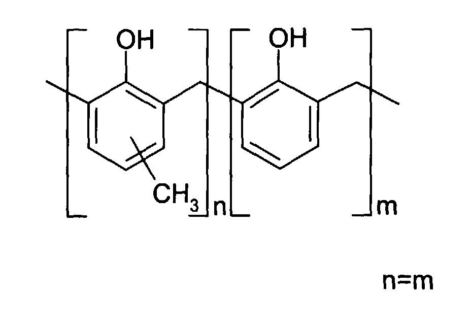
- 4 wt% LB 744 - a cresol novolak resin marketed by Bakelite, UK.
- 0.4 wt% KF654B PINA as supplied by Riedel de Haan UK,
Middlesex, UK, and believed to have the structure:

- 0.4 wt% crystal violet (basic violet 3, C.I. 42555,
Gentian Violet) as supplied by Aldrich Chemical Company of
Dorset, UK, and believed to have the structure:

- 1.2 wt% Silikophen P50X: a phenyl methyl siloxane as supplied by Tego Chemie Service GmbH of Essen, Germany.
- 80 wt% 1-methoxypropan-2-ol/xylene (98:2 v:v)
-
- The coating solution was reverse roller coated onto the substrate. The solution concentration had been selected to provide the dry coating with a coating weight of 2gm-2. After thorough drying at 110°C for 30 seconds in a hot air displacement oven the substrate was wound up as a coil. The coil was cut to form individual precursors of size about 115cm x 92cm, which were laid horizontally in stacks on pallets, typically with about 1500 precursors in a stack, and with an interleaving sheet between adjacent precursors. The interleaving sheets were a polythene coated paper No 22, 6gm-2, available from Samuel Grant, Leeds, UK. At both the top of the stack, 5 dummy precursors were placed. Four such stacks were made. Three of them were wrapped in polythene in accordance with the invention. The polythene was cast clear polythene film sold under the trade name POLYFLEX by Samuel Grant, having a thickness of 23µm, film density of 0.918, and width of 50cm. To effect the wrapping a stack was placed on a turntable adjacent to a polythene film feeder, from which the polythene film could be drawn. The turntable was rotated 11 times to provide 11 tight wraps of polythene, while a feeder traversed up and down. The edges of each plate were very well covered by the polythene, which conformed closely to irregularities of the vertical sides of the stack. The top and bottom surfaces of the stack were not covered over by the polythene, but at the top the free edges of the polythene were taped to the top surface of the upper dummy plate. The four stacks, three wrapped and one unwrapped, were then placed in an oven for 72 hours at 55°C. The oven was a 2.3m x 2.3m x 2.3m oven recirculating warm air supplied by two fans via plenums on two sides of the oven. The recirculating volume was 5500 cubic feet per minute (2.6m3/second). At the end of this period the stacks were removed from the oven and put in ambient air to cool entirely to ambient temperature, and the wrapping was then removed. Precursors from within the stacks were tested across their entire surface by imaging them using infra-red radiation. The imaging took place on a Creo TRENDSETTER, available from Creo Products, Burnaby, Canada, using radiation of wavelength 830 nm at a drum speed of 138rpm, a laser power of 10W and an imaging energy density of 200 mJ/cm-2. Development took place in a Kodak Polychrome Graphics Mercury Mark V processor containing a 14 wt% sodium metasilicate developer at 22.5°C set at a speed of 750mm/min. Performance was assessed by comparing actual screen (dot) densities with expected densities, using a Gretag D19C densitometer, available from Colour Data Systems Limited, the Wirral, UK. The sensitometric performance of all samples in each test was near identical, and acceptable, in the center of the precursors. However unacceptable performance at the edges was noted in printing forms from the comparative unwrapped stack only, defined below in terms of "edge trim requirements," of a representative precursor from within each stack. "Edge trim requirements" as used herein denotes the width which had to be removed from an edge to remove a region of unacceptable performance.
-
- (1 unwrapped, 3 wrapped stacks, all heat treated together)
-
- In further tests two wrapped stacks were heat treated. The precursors, stacks, wrapping, heat treatment and cooling were all as previously described. Immediately after removal from the oven, the wrapping was stripped from one stack only and both stacks were left to cool at ambient temperature. In both cases the edge trim requirement was zero.
- Laboratory scale tests were also carried out on unwrapped and wrapped precursors using humidity control. Heat treatment was effected in a Sanyo GallenKamp environmental chamber with humidity control provision, Model No. HCCO 19.PF1.F supplied by Sanyo Gallenkamp of Leicester, UK. The precursors, heat treatment and cooling were as described above. However a stack was made up as follows: a wrapped section with ten dummy precursors at the top, then ten precursors to be tested, then ten dummy precursors at the bottom; beneath that wrapped section, ten unwrapped precursors to be tested, then (so, at the very bottom of the stack) ten unwrapped dummy precursors. Wrapping did not employ polythene, but an unbleached, unglazed Kraft 90 gm-2 paper, coated with matt black low density polythene, 20gm-2, as supplied by Samuel Grant. In these experiments no edge effects on imaging and development were observed in the test precursors heat treated at a relative humidity of 40%, 60% and 80%. For those heat treated at a relative humidity of 20%, edge imperfections were observed in the test precursors. No differences were observed between wrapped and unwrapped precursors which were heat treated at the same humidity.
- Laboratory tests were also carried out on unwrapped and wrapped precursors using humidity control. The precursors were as described above for Example 1. Heat treatment at 55°C was effected in a Sanyo Gallenkamp environmental chamber as described above, with humidity control provision. A stack was made as follows: a wrapped section with ten dummy precursors at the top, then ten precursors to be tested, then ten dummy precursors underneath, and beneath that wrapped section, ten unwrapped precursors to be tested, then finally (so, at the very bottom of the stack) ten unwrapped dummy precursors.
- Wrapping did not employ polythene, but an unbleached, unglazed Kraft 90 gm-2 paper, coated with matt black low density polythene, 20gm-2, as supplied by Samuel Grant. Precursors from within the wrapped and unwrapped testing precursors were tested across their entire surface. Imaging took place on a Creo TRENDSETTER, set up as described above. Development took place in a Kodak Polychrome Graphics Mercury Mark V processor, set up as described above. Performance was assessed by comparing actual screen densities with expected densities, using the Gretag D19C densitometer.
- In these experiments no edge effects on imaging and development were observed in the test precursors heat treated at a relative humidity of 30% at 55°C and 35% at 55°C. However, for those heat treated at a relative humidity of 20% at 55°C and 25% at 55°C, edge imperfections were observed in the test precursors. No differences were observed between wrapped and unwrapped precursors which were heat treated at the same humidity.
-
Expected Dot Readings / % Actual Dot Readings / % 2 1 2 2 2 2 1 1 5 4 4 5 5 5 5 4 10 8 9 10 10 10 9 8 20 17 18 19 19 19 18 17 30 27 28 29 29 29 28 27 40 37 38 39 39 39 38 37 50 47 48 49 49 49 48 47 60 57 58 59 59 59 58 58 70 68 69 70 70 70 69 69 80 79 79 80 80 80 79 79 90 89 90 90 91 91 90 90 95 95 95 95 96 96 95 95 Left Hand Side Plate Edge Middle of Plate Right Hand Side Plate Edge -
Expected Dot Readings / % Actual Dot Readings / % 2 2 2 2 2 2 2 2 5 5 5 5 5 5 5 5 10 10 10 10 10 10 10 9 20 19 19 20 19 19 20 19 30 28 29 29 29 29 29 28 40 38 38 39 39 39 39 38 50 48 49 49 49 49 49 48 60 58 59 59 59 59 59 58 70 68 69 69 69 69 69 68 80 79 79 79 79 79 79 79 90 89 89 90 90 90 90 89 95 95 95 95 95 95 95 95 Left Hand Side Plate Edge Middle of Plate Right Hand Side Plate Edge -
Expected Dot Readings/% Actual Dot Readings / % 2 2 2 2 2 2 2 2 5 5 5 5 5 5 5 5 10 10 10 10 10 10 10 10 20 20 20 20 20 20 20 20 30 30 30 30 30 30 30 30 40 40 40 40 40 40 40 40 50 50 50 50 50 50 50 50 60 60 60 60 60 60 60 60 70 70 70 70 70 70 70 70 80 80 80 80 80 80 80 80 90 90 90 90 90 90 90 91 95 95 95 95 95 95 95 95 Left Hand Side Plate Edge Middle of Plate Right Hand Side Plate Edge -
Expected Dot Readings/% Actual Dot Readings / % 2 2 2 2 2 2 2 2 5 5 5 5 5 5 5 5 10 10 10 10 10 10 10 10 20 20 20 20 20 20 20 20 30 30 30 30 30 30 30 30 40 40 40 40 40 40 40 40 50 50 50 50 50 50 50 50 60 60 60 60 60 60 60 60 70 70 70 70 70 70 70 70 80 81 80 80 80 80 80 80 90 90 90 90 90 90 90 90 95 95 95 95 95 95 95 95 Left Hand Side Plate Edge Middle of Plate Right Hand Side Plate Edge - In a further test, a larger stack of test precursors was subjected to the heat treatment. The precursors were as described above for Example 1.
- A stack was made up as follows: a wrapped section with ten dummy precursors at the top, then 110 precursors to be tested, then ten dummy precursors at the bottom. The wrapping and testing were all as previously described. The precursors were placed in the Sanyo Gallenkamp environmental chamber at 55°C, 40% relative humidity for 72 hours. In this experiment no edge effects on imaging and development were observed in the test precursors at the top or bottom of the stack.
-
Expected Dot Readings / % Actual Dot Readings / % 2 2 2 2 2 2 2 2 5 5 5 5 5 5 5 5 10 10 10 10 10 10 10 10 20 20 20 20 20 20 20 20 30 30 30 30 30 30 30 30 40 40 40 40 40 40 40 40 50 50 50 50 50 50 50 50 60 60 60 60 60 60 60 60 70 70 70 70 70 70 70 70 80 80 80 80 80 80 80 80 90 91 91 91 91 91 91 91 95 96 96 96 96 96 96 96 Left Hand Side Plate Edge Middle of Plate Right Hand Side Plate Edge -
Expected Dot Readings / % Actual Dot Readings / % 2 2 2 2 2 2 2 2 5 5 5 5 5 5 5 5 10 10 10 10 10 10 10 10 20 20 20 20 20 20 20 20 30 30 30 30 30 30 30 30 40 40 40 40 40 40 40 40 50 50 50 50 50 50 50 50 60 60 60 60 60 60 60 60 70 70 70 70 70 70 70 70 80 80 80 80 80 80 80 80 90 91 91 91 91 91 91 91 95 96 96 96 96 96 96 96 Left Hand Side Plate Edge Middle of Plate Right Hand Side Plate Edge - Precursors were prepared as described above for Example 1. For heat treatment they were laid horizontally in stacks on pallets, typically with about 1000 precursors in a stack, and with an interleaving sheet between adjacent precursors. The interleaving sheets were a polythene coated paper, no. 22, 6gm-2, available from Samuel Grant. At the top of the stack, 5 dummy precursors were placed. The substantially water impermeable barrier material employed to wrap around the stack was a SELLOTAPE metalised polyester tape 1695/91/92 as supplied by Samuel Grant. The barrier material had adhesive supplied on one side. It was manually stuck to the sides of the plate stack. Just one layer of material was used. At the top of the stack the free edges were stuck down to the face of the dummy precursor. In this way, the edges of the plate were completely covered in the barrier material.
- Two stacks, one wrapped as described and one unwrapped were then placed in an oven for 72 hours at 55°C. The oven was a 2.3m x 2.3m x 2.3 m oven, recirculating warm air supplied by two fans via plenums on respective sides of the oven. The recirculating volume was 5500 cubic feet (186 m3) per minute. At the end of this period, the stacks were removed from the oven and put in ambient air to cool entirely to ambient temperature, and the wrapping was then removed. Precursors from within each stack were tested across their entire surface. Imaging of the thermal precursors took place on a Creo TRENDSETTER, set up as described above and development took place in a Kodak Polychrome Graphics Mercury Mark V processor, set up as described above. Performance was assessed by comparing actual screen densities with expected densities, using the Gretag D19C densitometer.
- The sensitometric performance of all samples in the test was nearly identical, and acceptable, in the centers of the precursors. However unacceptable performance at the edges was noted in the printing forms from the comparative unwrapped stack only, defined below in terms of "edge trim requirements," of a representative precursor from within each stack.
-
Edge 1 Edge 2 Edge 3 Edge 4 Unwrapped 80 60 65 50 Wrapped 0 0 0 0 - The invention is not restricted to the details of the foregoing embodiments. The invention extends to any feature, or any combination, of the features disclosed in this specification (including any accompanying claims, abstract and drawings), or to any step, or any combination of the steps of any method or process so disclosed.
| Edge 1 | Edge 2 | Edge 3 | Edge 4 | |
| Unwrapped | 100 | 55 | 65 | 45 |
| Wrapped 1 | 0 | 0 | 0 | 0 |
| Wrapped 2 | 0 | 0 | 0 | 0 |
| Wrapped 3 | 0 | 0 | 0 | 0 |
Claims (17)
- A method of providing a precursor which comprises an imageable coating comprising a polymeric composition on a substrate, wherein the method comprises a heat treatment step applied to the precursor, the heat treatment step taking place under conditions which inhibit the removal of moisture from the precursor during the heat treatment.
- The method of claim 1, wherein the polymeric composition is positive working.
- The method of claim 1 or 2, wherein the polymeric composition includes a polymer having hydroxyl groups.
- The method of claim 3, wherein the polymeric composition includes a polymer selected from a phenolic resin and a poly(hydroxystyrene) resin.
- The method of claim 4, wherein the polymeric composition includes a novolak resin.
- The method of any preceding claim, wherein the glass transition temperature of the coating is not exceeded in the heat treatment.
- The method of any preceding claim, wherein the precursor is held at an elevated temperature, for at least 12 hours in the heat treatment.
- The method of any preceding claim, wherein the precursor is held at an elevated temperature in the range 40-90°C during the heat treatment.
- The method of any preceding claim, wherein the method is applied to a stack of at least 100 precursors.
- The method of any preceding claim, wherein the removal of moisture is inhibited by wrapping or encasing the precursor in a substantially water-impermeable material.
- The method of any preceding claim, wherein the removal of moisture is inhibited by carrying out the heat treatment in an environment having elevated moisture content.
- The method of any preceding claim, wherein said coating is such that it may be patternwise imaged by direct heat; or by charged particle radiation or electromagnetic radiation, in the latter cases said radiation being converted to heat by the coating.
- The method of claim 12, wherein the coating comprises a radiation-absorbing compound able to absorb electromagnetic radiation entirely or predominantly in the range 600 to 1400 nm and convert it to heat.
- The method of any preceding claim, wherein the coating comprises insolubilizer means which acts to inhibit the dissolution of the coating in a developer prior to imaging.
- A positive working lithographic printing form precursor produced by a method of any preceding claim.
- A positive working electronic part precursor produced by a method of any of claims 1 to 14.
- A method of producing an imaged article, comprising:(a) preparing a precursor by a method of any of claims 1 to 14;(b) imagewise exposing the coating; and(c) contacting the exposed coating with an aqueous developer.
Applications Claiming Priority (4)
| Application Number | Priority Date | Filing Date | Title |
|---|---|---|---|
| US14692099P | 1999-08-03 | 1999-08-03 | |
| US146920P | 1999-08-03 | ||
| US09/587,813 US6706466B1 (en) | 1999-08-03 | 2000-06-06 | Articles having imagable coatings |
| US587813 | 2000-06-06 |
Publications (3)
| Publication Number | Publication Date |
|---|---|
| EP1074889A2 true EP1074889A2 (en) | 2001-02-07 |
| EP1074889A3 EP1074889A3 (en) | 2001-11-14 |
| EP1074889B1 EP1074889B1 (en) | 2006-11-02 |
Family
ID=26844414
Family Applications (1)
| Application Number | Title | Priority Date | Filing Date |
|---|---|---|---|
| EP00305263A Expired - Lifetime EP1074889B1 (en) | 1999-08-03 | 2000-06-21 | Thermal treatment of imagable coatings |
Country Status (3)
| Country | Link |
|---|---|
| US (1) | US6706466B1 (en) |
| EP (1) | EP1074889B1 (en) |
| DE (1) | DE60031608T2 (en) |
Cited By (32)
| Publication number | Priority date | Publication date | Assignee | Title |
|---|---|---|---|---|
| US6723489B2 (en) | 2002-01-30 | 2004-04-20 | Kodak Polychrome Graphics Llp | Printing form precursors |
| WO2006083903A1 (en) * | 2005-02-04 | 2006-08-10 | Printing Research, Inc. | Computer to plate color sensor and drying/curing system and method |
| US7195859B2 (en) * | 2002-10-04 | 2007-03-27 | Agfa-Gevaert | Method of making a lithographic printing plate precursor |
| US7225560B2 (en) | 2005-02-04 | 2007-06-05 | Printing Research, Inc. | Computer to plate curing system |
| WO2008001127A2 (en) | 2006-06-30 | 2008-01-03 | Imagichem Limited | Composition, article, its manufacture and use |
| CN100439119C (en) * | 2002-10-04 | 2008-12-03 | 爱克发印艺公司 | Method of making a lithographic printing plate precursor |
| CN100439120C (en) * | 2002-10-04 | 2008-12-03 | 爱克发印艺公司 | Method of making a lithographic printing plate precursor |
| US7467587B2 (en) | 2004-04-21 | 2008-12-23 | Agfa Graphics, N.V. | Method for accurate exposure of small dots on a heat-sensitive positive-working lithographic printing plate material |
| US7485404B2 (en) * | 2003-11-21 | 2009-02-03 | Yamamoto Chemicals, Inc. | Nonsolvate-form crystal of polymethine compound and process for producing the same |
| EP2065211A1 (en) | 2007-11-30 | 2009-06-03 | Agfa Graphics N.V. | A method for treating a lithographic printing plate |
| EP2098376A1 (en) | 2008-03-04 | 2009-09-09 | Agfa Graphics N.V. | A method for making a lithographic printing plate support |
| EP2106924A1 (en) | 2008-03-31 | 2009-10-07 | Agfa Graphics N.V. | A method for treating a lithographic printing plate |
| EP2263874A1 (en) | 2009-06-18 | 2010-12-22 | Agfa Graphics N.V. | A lithographic printing plate precursor |
| WO2011067382A1 (en) | 2009-12-04 | 2011-06-09 | Agfa Graphics Nv | A lithographic printing plate precursor |
| WO2012101046A1 (en) | 2011-01-25 | 2012-08-02 | Agfa Graphics Nv | A lithographic printing plate precursor |
| EP2489512A1 (en) | 2011-02-18 | 2012-08-22 | Agfa Graphics N.V. | A lithographic printing plate precursor |
| US8419923B2 (en) | 2006-08-03 | 2013-04-16 | Agfa Graphics Nv | Lithographic printing plate support |
| CN101395536B (en) * | 2006-03-02 | 2013-05-22 | 伊斯曼柯达公司 | Heat treatment of multilayer imageable elements |
| WO2014106554A1 (en) | 2013-01-01 | 2014-07-10 | Agfa Graphics Nv | (ethylene, vinyl acetal) copolymers and their use in lithographic printing plate precursors |
| EP2636525A3 (en) * | 2012-03-06 | 2014-10-29 | Presstek, Inc. | Lithographic imaging and printing with positive-working photoresponsive printing members. |
| EP2933278A1 (en) | 2014-04-17 | 2015-10-21 | Agfa Graphics Nv | (Ethylene, vinyl acetal) copolymers and their use in lithographic printing plate precursors |
| EP2944657A1 (en) | 2014-05-15 | 2015-11-18 | Agfa Graphics Nv | (Ethylene, Vinyl Acetal) Copolymers and Their Use In Lithographic Printing Plate Precursors |
| EP2955198A1 (en) | 2014-06-13 | 2015-12-16 | Agfa Graphics Nv | (Ethylene, vinyl acetal) copolymers and their use in lithographic printing plate precursors |
| EP2963496A1 (en) | 2014-06-30 | 2016-01-06 | Agfa Graphics Nv | A lithographic printing plate precursor including ( ethylene, vinyl acetal ) copolymers |
| EP3032334A1 (en) | 2014-12-08 | 2016-06-15 | Agfa Graphics Nv | A system for reducing ablation debris |
| EP3130465A1 (en) | 2015-08-12 | 2017-02-15 | Agfa Graphics Nv | Heat-sensitive lithographic printing plate precursor |
| EP3157310A1 (en) | 2015-10-12 | 2017-04-19 | Agfa Graphics Nv | An entry sheet for perforating electric boards such as printed circuit boards |
| EP3170662A1 (en) | 2015-11-20 | 2017-05-24 | Agfa Graphics Nv | A lithographic printing plate precursor |
| WO2017157571A1 (en) | 2016-03-16 | 2017-09-21 | Agfa Graphics Nv | Method and apparatus for processing a lithographic printing plate |
| EP3637188A1 (en) | 2018-10-08 | 2020-04-15 | Agfa Nv | An effervescent developer precursor for processing a lithographic printing plate precursor |
| EP3778253A1 (en) | 2019-08-13 | 2021-02-17 | Agfa Nv | Method for processing a lithographic printing plate |
| EP4239411A1 (en) | 2022-03-04 | 2023-09-06 | Eco3 Bv | Method and apparatus for processing a lithographic printing plate precursor |
Families Citing this family (10)
| Publication number | Priority date | Publication date | Assignee | Title |
|---|---|---|---|---|
| US7175969B1 (en) | 2006-07-18 | 2007-02-13 | Eastman Kodak Company | Method of preparing negative-working radiation-sensitive elements |
| US7582407B2 (en) * | 2007-07-09 | 2009-09-01 | Eastman Kodak Company | Imageable elements with low pH developer solubility |
| US20100227269A1 (en) | 2009-03-04 | 2010-09-09 | Simpson Christopher D | Imageable elements with colorants |
| US7749647B1 (en) * | 2009-07-17 | 2010-07-06 | Tesla Motors, Inc. | Method and apparatus for maintaining cell wall integrity during thermal runaway using a high yield strength outer sleeve |
| US8383319B2 (en) | 2009-08-25 | 2013-02-26 | Eastman Kodak Company | Lithographic printing plate precursors and stacks |
| US8936899B2 (en) | 2012-09-04 | 2015-01-20 | Eastman Kodak Company | Positive-working lithographic printing plate precursors and use |
| US8632940B2 (en) | 2011-04-19 | 2014-01-21 | Eastman Kodak Company | Aluminum substrates and lithographic printing plate precursors |
| US8722308B2 (en) | 2011-08-31 | 2014-05-13 | Eastman Kodak Company | Aluminum substrates and lithographic printing plate precursors |
| US20130255515A1 (en) | 2012-03-27 | 2013-10-03 | Celin Savariar-Hauck | Positive-working lithographic printing plate precursors |
| US9588429B1 (en) | 2015-09-03 | 2017-03-07 | Eastman Kodak Company | Lithographic developer composition and method of use |
Citations (2)
| Publication number | Priority date | Publication date | Assignee | Title |
|---|---|---|---|---|
| US5667942A (en) * | 1993-12-28 | 1997-09-16 | Fujitsu Limited | Resist pattern forming method |
| WO1999021715A1 (en) * | 1997-10-29 | 1999-05-06 | Kodak Polychrome Graphics Company Ltd. | Manufacture of lithographic printing forms |
Family Cites Families (22)
| Publication number | Priority date | Publication date | Assignee | Title |
|---|---|---|---|---|
| GB1245924A (en) | 1967-09-27 | 1971-09-15 | Agfa Gevaert | Improvements relating to thermo-recording |
| US4708925A (en) | 1984-12-11 | 1987-11-24 | Minnesota Mining And Manufacturing Company | Photosolubilizable compositions containing novolac phenolic resin |
| US5085972A (en) | 1990-11-26 | 1992-02-04 | Minnesota Mining And Manufacturing Company | Alkoxyalkyl ester solubility inhibitors for phenolic resins |
| US5286612A (en) | 1992-10-23 | 1994-02-15 | Polaroid Corporation | Process for generation of free superacid and for imaging, and imaging medium for use therein |
| TW338125B (en) * | 1993-02-26 | 1998-08-11 | Hoechst Celanese Corp | Novel matriz resin and its preparation and use in high-temperature stable photoimageable compositions |
| US5372915A (en) | 1993-05-19 | 1994-12-13 | Eastman Kodak Company | Method of making a lithographic printing plate containing a resole resin and a novolac resin in the radiation sensitive layer |
| GB9322705D0 (en) | 1993-11-04 | 1993-12-22 | Minnesota Mining & Mfg | Lithographic printing plates |
| EP0672954B1 (en) | 1994-03-14 | 1999-09-15 | Kodak Polychrome Graphics LLC | Radiation-sensitive composition containing a resole resin, a novolac resin, an infrared absorber and a triazine and use thereof in lithographic printing plates |
| US5441850A (en) | 1994-04-25 | 1995-08-15 | Polaroid Corporation | Imaging medium and process for producing an image |
| JPH088170A (en) | 1994-06-23 | 1996-01-12 | Fujitsu Ltd | Method of forming polyimide resin film, and device for forming polyimide resin film |
| US5466557A (en) | 1994-08-29 | 1995-11-14 | Eastman Kodak Company | Radiation-sensitive composition containing a resole resin, a novolac resin, a latent bronsted acid, an infrared absorber and terephthalaldehyde and use thereof in lithographic printing plates |
| GB9426206D0 (en) | 1994-12-23 | 1995-02-22 | Horsell Plc | Lithographic plate |
| US5491046A (en) | 1995-02-10 | 1996-02-13 | Eastman Kodak Company | Method of imaging a lithographic printing plate |
| DE69700397T2 (en) | 1996-04-23 | 2000-04-13 | Kodak Polychrome Graphics Co | PRECURSOR OF A LITHOGRAPHIC PRINTING FORM AND THEIR USE IN IMAGING THROUGH HEAT |
| DE69608679D1 (en) | 1996-07-19 | 2000-07-06 | Agfa Gevaert Nv | IR radiation-sensitive imaging element and method for producing lithographic printing plates with this element |
| TW464944B (en) * | 1997-01-16 | 2001-11-21 | Tokyo Electron Ltd | Baking apparatus and baking method |
| DE69801363T2 (en) | 1997-07-05 | 2002-05-23 | Kodak Polychrome Graphics Llc | IMAGING PROCESS |
| IL134522A (en) | 1997-08-14 | 2003-12-10 | Kodak Polychrome Graphics Co | Method of making masks and electronic parts |
| GB9722862D0 (en) | 1997-10-29 | 1997-12-24 | Horsell Graphic Ind Ltd | Pattern formation |
| DE19910363B4 (en) * | 1998-03-10 | 2007-08-30 | Mitsubishi Paper Mills Ltd. | Positive photosensitive imageable element |
| CA2349307A1 (en) | 1998-11-16 | 2000-05-25 | Katsuhiko Hidaka | Positive-working photosensitive lithographic printing plate and method for producing the same |
| US6391524B2 (en) * | 1999-11-19 | 2002-05-21 | Kodak Polychrome Graphics Llc | Article having imagable coatings |
-
2000
- 2000-06-06 US US09/587,813 patent/US6706466B1/en not_active Expired - Fee Related
- 2000-06-21 DE DE60031608T patent/DE60031608T2/en not_active Expired - Lifetime
- 2000-06-21 EP EP00305263A patent/EP1074889B1/en not_active Expired - Lifetime
Patent Citations (2)
| Publication number | Priority date | Publication date | Assignee | Title |
|---|---|---|---|---|
| US5667942A (en) * | 1993-12-28 | 1997-09-16 | Fujitsu Limited | Resist pattern forming method |
| WO1999021715A1 (en) * | 1997-10-29 | 1999-05-06 | Kodak Polychrome Graphics Company Ltd. | Manufacture of lithographic printing forms |
Non-Patent Citations (1)
| Title |
|---|
| DATABASE WPI Section Ch, Week 199611 Derwent Publications Ltd., London, GB; Class A05, AN 1996-102500 XP002177606 & JP 08 008170 A (FUJITSU), 12 January 1996 (1996-01-12) * |
Cited By (48)
| Publication number | Priority date | Publication date | Assignee | Title |
|---|---|---|---|---|
| US6723489B2 (en) | 2002-01-30 | 2004-04-20 | Kodak Polychrome Graphics Llp | Printing form precursors |
| CN100439120C (en) * | 2002-10-04 | 2008-12-03 | 爱克发印艺公司 | Method of making a lithographic printing plate precursor |
| US7195859B2 (en) * | 2002-10-04 | 2007-03-27 | Agfa-Gevaert | Method of making a lithographic printing plate precursor |
| CN100439119C (en) * | 2002-10-04 | 2008-12-03 | 爱克发印艺公司 | Method of making a lithographic printing plate precursor |
| US7485404B2 (en) * | 2003-11-21 | 2009-02-03 | Yamamoto Chemicals, Inc. | Nonsolvate-form crystal of polymethine compound and process for producing the same |
| US7467587B2 (en) | 2004-04-21 | 2008-12-23 | Agfa Graphics, N.V. | Method for accurate exposure of small dots on a heat-sensitive positive-working lithographic printing plate material |
| US7685738B2 (en) | 2005-02-04 | 2010-03-30 | Printing Research, Inc. | Computer to plate color sensor and drying/curing system and method |
| US7225560B2 (en) | 2005-02-04 | 2007-06-05 | Printing Research, Inc. | Computer to plate curing system |
| WO2006083903A1 (en) * | 2005-02-04 | 2006-08-10 | Printing Research, Inc. | Computer to plate color sensor and drying/curing system and method |
| CN101395536B (en) * | 2006-03-02 | 2013-05-22 | 伊斯曼柯达公司 | Heat treatment of multilayer imageable elements |
| WO2008001127A2 (en) | 2006-06-30 | 2008-01-03 | Imagichem Limited | Composition, article, its manufacture and use |
| US8419923B2 (en) | 2006-08-03 | 2013-04-16 | Agfa Graphics Nv | Lithographic printing plate support |
| EP2065211A1 (en) | 2007-11-30 | 2009-06-03 | Agfa Graphics N.V. | A method for treating a lithographic printing plate |
| EP2098376A1 (en) | 2008-03-04 | 2009-09-09 | Agfa Graphics N.V. | A method for making a lithographic printing plate support |
| EP2106924A1 (en) | 2008-03-31 | 2009-10-07 | Agfa Graphics N.V. | A method for treating a lithographic printing plate |
| EP2263874A1 (en) | 2009-06-18 | 2010-12-22 | Agfa Graphics N.V. | A lithographic printing plate precursor |
| US8771918B2 (en) | 2009-06-18 | 2014-07-08 | Agfa Graphics N.V. | Lithographic printing plate precursor |
| WO2011067382A1 (en) | 2009-12-04 | 2011-06-09 | Agfa Graphics Nv | A lithographic printing plate precursor |
| US9738064B2 (en) | 2009-12-04 | 2017-08-22 | Agfa Graphics N.V. | Lithographic printing plate precursor |
| WO2012101046A1 (en) | 2011-01-25 | 2012-08-02 | Agfa Graphics Nv | A lithographic printing plate precursor |
| EP2489512A1 (en) | 2011-02-18 | 2012-08-22 | Agfa Graphics N.V. | A lithographic printing plate precursor |
| WO2012110359A1 (en) | 2011-02-18 | 2012-08-23 | Agfa Graphics Nv | A lithographic printing plate precursor |
| US9029066B2 (en) | 2011-02-18 | 2015-05-12 | Agfa Graphics Nv | Lithographic printing plate precursor |
| EP2636525A3 (en) * | 2012-03-06 | 2014-10-29 | Presstek, Inc. | Lithographic imaging and printing with positive-working photoresponsive printing members. |
| WO2014106554A1 (en) | 2013-01-01 | 2014-07-10 | Agfa Graphics Nv | (ethylene, vinyl acetal) copolymers and their use in lithographic printing plate precursors |
| EP2933278A1 (en) | 2014-04-17 | 2015-10-21 | Agfa Graphics Nv | (Ethylene, vinyl acetal) copolymers and their use in lithographic printing plate precursors |
| EP2944657A1 (en) | 2014-05-15 | 2015-11-18 | Agfa Graphics Nv | (Ethylene, Vinyl Acetal) Copolymers and Their Use In Lithographic Printing Plate Precursors |
| EP2955198A1 (en) | 2014-06-13 | 2015-12-16 | Agfa Graphics Nv | (Ethylene, vinyl acetal) copolymers and their use in lithographic printing plate precursors |
| WO2015189092A1 (en) | 2014-06-13 | 2015-12-17 | Agfa Graphics Nv | (ethylene, vinyl acetal) copolymers and their use in lithographic printing plate precursors |
| EP2963496A1 (en) | 2014-06-30 | 2016-01-06 | Agfa Graphics Nv | A lithographic printing plate precursor including ( ethylene, vinyl acetal ) copolymers |
| WO2016001023A1 (en) | 2014-06-30 | 2016-01-07 | Agfa Graphics Nv | A lithographic printing plate precursor including (ethylene, vinyl acetal) copolymers |
| EP3032334A1 (en) | 2014-12-08 | 2016-06-15 | Agfa Graphics Nv | A system for reducing ablation debris |
| EP3130465A1 (en) | 2015-08-12 | 2017-02-15 | Agfa Graphics Nv | Heat-sensitive lithographic printing plate precursor |
| EP3157310A1 (en) | 2015-10-12 | 2017-04-19 | Agfa Graphics Nv | An entry sheet for perforating electric boards such as printed circuit boards |
| EP3170662A1 (en) | 2015-11-20 | 2017-05-24 | Agfa Graphics Nv | A lithographic printing plate precursor |
| WO2017085002A1 (en) | 2015-11-20 | 2017-05-26 | Agfa Graphics Nv | A lithographic printing plate precursor |
| WO2017157571A1 (en) | 2016-03-16 | 2017-09-21 | Agfa Graphics Nv | Method and apparatus for processing a lithographic printing plate |
| WO2017157572A1 (en) | 2016-03-16 | 2017-09-21 | Agfa Graphics Nv | Apparatus for processing a lithographic printing plate and corresponding method |
| WO2017157576A1 (en) | 2016-03-16 | 2017-09-21 | Agfa Graphics Nv | Method for processing a lithographic printing plate |
| WO2017157578A1 (en) | 2016-03-16 | 2017-09-21 | Agfa Graphics Nv | Method for processing a lithographic printing plate |
| WO2017157575A1 (en) | 2016-03-16 | 2017-09-21 | Agfa Graphics Nv | Method and apparatus for processing a lithographic printing plate |
| WO2017157579A1 (en) | 2016-03-16 | 2017-09-21 | Agfa Graphics Nv | Method for processing a lithographic printing plate |
| EP3637188A1 (en) | 2018-10-08 | 2020-04-15 | Agfa Nv | An effervescent developer precursor for processing a lithographic printing plate precursor |
| WO2020074258A1 (en) | 2018-10-08 | 2020-04-16 | Agfa Nv | An effervescent developer precursor for processing a lithographic printing plate precursor |
| EP3778253A1 (en) | 2019-08-13 | 2021-02-17 | Agfa Nv | Method for processing a lithographic printing plate |
| WO2021028385A1 (en) | 2019-08-13 | 2021-02-18 | Agfa Nv | Method for processing a lithographic printing plate |
| EP4239411A1 (en) | 2022-03-04 | 2023-09-06 | Eco3 Bv | Method and apparatus for processing a lithographic printing plate precursor |
| WO2023165919A1 (en) | 2022-03-04 | 2023-09-07 | Eco3 Bv | Method and apparatus for processing a lithographic printing plate precursor |
Also Published As
| Publication number | Publication date |
|---|---|
| EP1074889B1 (en) | 2006-11-02 |
| EP1074889A3 (en) | 2001-11-14 |
| DE60031608T2 (en) | 2007-08-23 |
| US6706466B1 (en) | 2004-03-16 |
| DE60031608D1 (en) | 2006-12-14 |
Similar Documents
| Publication | Publication Date | Title |
|---|---|---|
| US6706466B1 (en) | Articles having imagable coatings | |
| EP1074386B1 (en) | Heat treatment method for obtaining imagable coatings | |
| EP1024958B1 (en) | Manufacture of lithographic printing forms | |
| US6537735B1 (en) | Pattern-forming methods and radiation sensitive materials | |
| EP1024963B1 (en) | Pattern formation | |
| US6391524B2 (en) | Article having imagable coatings | |
| EP1003645B1 (en) | Method of making electronic parts | |
| EP1101608B1 (en) | Articles having imageable coatings | |
| EP1079973A1 (en) | Waterless lithographic plate | |
| US6352814B1 (en) | Method of forming a desired pattern | |
| US6248505B1 (en) | Method for producing a predetermined resist pattern | |
| US6723489B2 (en) | Printing form precursors | |
| EP1307341B1 (en) | Lithographic printing form and method of preparation and use thereof | |
| US6894000B2 (en) | Method for preparing imaged members and imaged members prepared thereby | |
| US6551763B1 (en) | Method for manufacture of electronic parts | |
| EP1333977A1 (en) | Compositions comprising a pigment |
Legal Events
| Date | Code | Title | Description |
|---|---|---|---|
| PUAI | Public reference made under article 153(3) epc to a published international application that has entered the european phase |
Free format text: ORIGINAL CODE: 0009012 |
|
| AK | Designated contracting states |
Kind code of ref document: A2 Designated state(s): BE DE FR GB IT NL Kind code of ref document: A2 Designated state(s): AT BE CH CY DE DK ES FI FR GB GR IE IT LI LU MC NL PT SE |
|
| AX | Request for extension of the european patent |
Free format text: AL;LT;LV;MK;RO;SI |
|
| PUAL | Search report despatched |
Free format text: ORIGINAL CODE: 0009013 |
|
| RIC1 | Information provided on ipc code assigned before grant |
Free format text: 7G 03F 7/16 A, 7B 41C 1/10 B |
|
| AK | Designated contracting states |
Kind code of ref document: A3 Designated state(s): AT BE CH CY DE DK ES FI FR GB GR IE IT LI LU MC NL PT SE |
|
| AX | Request for extension of the european patent |
Free format text: AL;LT;LV;MK;RO;SI |
|
| 17P | Request for examination filed |
Effective date: 20020117 |
|
| AKX | Designation fees paid |
Free format text: BE DE FR GB IT NL |
|
| 17Q | First examination report despatched |
Effective date: 20041021 |
|
| RAP1 | Party data changed (applicant data changed or rights of an application transferred) |
Owner name: KODAK POLYCHROME GRAPHICS COMPANY LTD. |
|
| GRAP | Despatch of communication of intention to grant a patent |
Free format text: ORIGINAL CODE: EPIDOSNIGR1 |
|
| GRAS | Grant fee paid |
Free format text: ORIGINAL CODE: EPIDOSNIGR3 |
|
| GRAA | (expected) grant |
Free format text: ORIGINAL CODE: 0009210 |
|
| AK | Designated contracting states |
Kind code of ref document: B1 Designated state(s): BE DE FR GB IT NL |
|
| PG25 | Lapsed in a contracting state [announced via postgrant information from national office to epo] |
Ref country code: IT Free format text: LAPSE BECAUSE OF FAILURE TO SUBMIT A TRANSLATION OF THE DESCRIPTION OR TO PAY THE FEE WITHIN THE PRESCRIBED TIME-LIMIT;WARNING: LAPSES OF ITALIAN PATENTS WITH EFFECTIVE DATE BEFORE 2007 MAY HAVE OCCURRED AT ANY TIME BEFORE 2007. THE CORRECT EFFECTIVE DATE MAY BE DIFFERENT FROM THE ONE RECORDED. Effective date: 20061102 |
|
| REG | Reference to a national code |
Ref country code: GB Ref legal event code: FG4D |
|
| REF | Corresponds to: |
Ref document number: 60031608 Country of ref document: DE Date of ref document: 20061214 Kind code of ref document: P |
|
| ET | Fr: translation filed | ||
| PLBE | No opposition filed within time limit |
Free format text: ORIGINAL CODE: 0009261 |
|
| STAA | Information on the status of an ep patent application or granted ep patent |
Free format text: STATUS: NO OPPOSITION FILED WITHIN TIME LIMIT |
|
| 26N | No opposition filed |
Effective date: 20070803 |
|
| PGFP | Annual fee paid to national office [announced via postgrant information from national office to epo] |
Ref country code: IT Payment date: 20110620 Year of fee payment: 12 |
|
| PGFP | Annual fee paid to national office [announced via postgrant information from national office to epo] |
Ref country code: BE Payment date: 20110705 Year of fee payment: 12 |
|
| BERE | Be: lapsed |
Owner name: KODAK POLYCHROME GRAPHICS CY LTD. Effective date: 20120630 |
|
| PG25 | Lapsed in a contracting state [announced via postgrant information from national office to epo] |
Ref country code: IT Free format text: LAPSE BECAUSE OF NON-PAYMENT OF DUE FEES Effective date: 20120621 |
|
| PG25 | Lapsed in a contracting state [announced via postgrant information from national office to epo] |
Ref country code: BE Free format text: LAPSE BECAUSE OF NON-PAYMENT OF DUE FEES Effective date: 20120630 |
|
| PGFP | Annual fee paid to national office [announced via postgrant information from national office to epo] |
Ref country code: FR Payment date: 20130618 Year of fee payment: 14 |
|
| PGFP | Annual fee paid to national office [announced via postgrant information from national office to epo] |
Ref country code: DE Payment date: 20130628 Year of fee payment: 14 |
|
| PGFP | Annual fee paid to national office [announced via postgrant information from national office to epo] |
Ref country code: GB Payment date: 20140527 Year of fee payment: 15 |
|
| PGFP | Annual fee paid to national office [announced via postgrant information from national office to epo] |
Ref country code: NL Payment date: 20140610 Year of fee payment: 15 |
|
| REG | Reference to a national code |
Ref country code: DE Ref legal event code: R119 Ref document number: 60031608 Country of ref document: DE |
|
| REG | Reference to a national code |
Ref country code: FR Ref legal event code: ST Effective date: 20150227 |
|
| REG | Reference to a national code |
Ref country code: DE Ref legal event code: R119 Ref document number: 60031608 Country of ref document: DE Effective date: 20150101 |
|
| PG25 | Lapsed in a contracting state [announced via postgrant information from national office to epo] |
Ref country code: DE Free format text: LAPSE BECAUSE OF NON-PAYMENT OF DUE FEES Effective date: 20150101 |
|
| PG25 | Lapsed in a contracting state [announced via postgrant information from national office to epo] |
Ref country code: FR Free format text: LAPSE BECAUSE OF NON-PAYMENT OF DUE FEES Effective date: 20140630 |
|
| GBPC | Gb: european patent ceased through non-payment of renewal fee |
Effective date: 20150621 |
|
| REG | Reference to a national code |
Ref country code: NL Ref legal event code: MM Effective date: 20150701 |
|
| PG25 | Lapsed in a contracting state [announced via postgrant information from national office to epo] |
Ref country code: GB Free format text: LAPSE BECAUSE OF NON-PAYMENT OF DUE FEES Effective date: 20150621 Ref country code: NL Free format text: LAPSE BECAUSE OF NON-PAYMENT OF DUE FEES Effective date: 20150701 |