EP1073308A2 - Optical switch and protocols for use therewith - Google Patents
Optical switch and protocols for use therewith Download PDFInfo
- Publication number
- EP1073308A2 EP1073308A2 EP00306485A EP00306485A EP1073308A2 EP 1073308 A2 EP1073308 A2 EP 1073308A2 EP 00306485 A EP00306485 A EP 00306485A EP 00306485 A EP00306485 A EP 00306485A EP 1073308 A2 EP1073308 A2 EP 1073308A2
- Authority
- EP
- European Patent Office
- Prior art keywords
- switching node
- wavelength
- switching
- connection
- optical
- Prior art date
- Legal status (The legal status is an assumption and is not a legal conclusion. Google has not performed a legal analysis and makes no representation as to the accuracy of the status listed.)
- Ceased
Links
Images


Classifications
-
- H—ELECTRICITY
- H04—ELECTRIC COMMUNICATION TECHNIQUE
- H04Q—SELECTING
- H04Q11/00—Selecting arrangements for multiplex systems
- H04Q11/0001—Selecting arrangements for multiplex systems using optical switching
- H04Q11/0005—Switch and router aspects
-
- H—ELECTRICITY
- H04—ELECTRIC COMMUNICATION TECHNIQUE
- H04B—TRANSMISSION
- H04B10/00—Transmission systems employing electromagnetic waves other than radio-waves, e.g. infrared, visible or ultraviolet light, or employing corpuscular radiation, e.g. quantum communication
- H04B10/27—Arrangements for networking
-
- H—ELECTRICITY
- H04—ELECTRIC COMMUNICATION TECHNIQUE
- H04J—MULTIPLEX COMMUNICATION
- H04J14/00—Optical multiplex systems
- H04J14/02—Wavelength-division multiplex systems
-
- H—ELECTRICITY
- H04—ELECTRIC COMMUNICATION TECHNIQUE
- H04Q—SELECTING
- H04Q11/00—Selecting arrangements for multiplex systems
- H04Q11/0001—Selecting arrangements for multiplex systems using optical switching
-
- H—ELECTRICITY
- H04—ELECTRIC COMMUNICATION TECHNIQUE
- H04Q—SELECTING
- H04Q11/00—Selecting arrangements for multiplex systems
- H04Q11/0001—Selecting arrangements for multiplex systems using optical switching
- H04Q11/0003—Details
-
- H—ELECTRICITY
- H04—ELECTRIC COMMUNICATION TECHNIQUE
- H04Q—SELECTING
- H04Q11/00—Selecting arrangements for multiplex systems
- H04Q11/0001—Selecting arrangements for multiplex systems using optical switching
- H04Q11/0062—Network aspects
-
- H—ELECTRICITY
- H04—ELECTRIC COMMUNICATION TECHNIQUE
- H04Q—SELECTING
- H04Q11/00—Selecting arrangements for multiplex systems
- H04Q11/0001—Selecting arrangements for multiplex systems using optical switching
- H04Q11/0005—Switch and router aspects
- H04Q2011/0007—Construction
- H04Q2011/0011—Construction using wavelength conversion
-
- H—ELECTRICITY
- H04—ELECTRIC COMMUNICATION TECHNIQUE
- H04Q—SELECTING
- H04Q11/00—Selecting arrangements for multiplex systems
- H04Q11/0001—Selecting arrangements for multiplex systems using optical switching
- H04Q11/0005—Switch and router aspects
- H04Q2011/0007—Construction
- H04Q2011/0016—Construction using wavelength multiplexing or demultiplexing
-
- H—ELECTRICITY
- H04—ELECTRIC COMMUNICATION TECHNIQUE
- H04Q—SELECTING
- H04Q11/00—Selecting arrangements for multiplex systems
- H04Q11/0001—Selecting arrangements for multiplex systems using optical switching
- H04Q11/0005—Switch and router aspects
- H04Q2011/0037—Operation
- H04Q2011/0039—Electrical control
-
- H—ELECTRICITY
- H04—ELECTRIC COMMUNICATION TECHNIQUE
- H04Q—SELECTING
- H04Q11/00—Selecting arrangements for multiplex systems
- H04Q11/0001—Selecting arrangements for multiplex systems using optical switching
- H04Q11/0062—Network aspects
- H04Q2011/0069—Network aspects using dedicated optical channels
-
- H—ELECTRICITY
- H04—ELECTRIC COMMUNICATION TECHNIQUE
- H04Q—SELECTING
- H04Q11/00—Selecting arrangements for multiplex systems
- H04Q11/0001—Selecting arrangements for multiplex systems using optical switching
- H04Q11/0062—Network aspects
- H04Q2011/0073—Provisions for forwarding or routing, e.g. lookup tables
-
- H—ELECTRICITY
- H04—ELECTRIC COMMUNICATION TECHNIQUE
- H04Q—SELECTING
- H04Q11/00—Selecting arrangements for multiplex systems
- H04Q11/0001—Selecting arrangements for multiplex systems using optical switching
- H04Q11/0062—Network aspects
- H04Q2011/0086—Network resource allocation, dimensioning or optimisation
-
- H—ELECTRICITY
- H04—ELECTRIC COMMUNICATION TECHNIQUE
- H04Q—SELECTING
- H04Q11/00—Selecting arrangements for multiplex systems
- H04Q11/0001—Selecting arrangements for multiplex systems using optical switching
- H04Q11/0062—Network aspects
- H04Q2011/009—Topology aspects
Definitions
- the present invention relates to the field of optical switching in general and, more particularly, to optical switching nodes for use in an optical network.
- the invention also pertains to protocols governing the behaviour of the switching nodes.
- high-capacity networks has been driven by the need to establish high-bandwidth data connections among remote sites, for instance, between clients and servers.
- the communications infrastructure for such a network is provided by one or more long-distance carriers serving the geographic region that encompasses the various remote sites.
- a carrier may lease fiber optic lines to customers wishing to establish high-capacity connections.
- optical switching nodes are then configured to support the desired connections.
- a carrier leases its fiber optic lines with a view to long-term usage thereof.
- switch configurations established at the time of provisioning the high-capacity connections are expected to remain in place for a period of months or years. Therefore, the switches in the network can be configured manually with virtually no impact on cost or quality of service provided.
- the invention can be described broadly as a switching node that includes an optical switch fabric, a wavelength conversion unit and a control unit.
- the optical switch fabric is connected to the control unit and is used for switching optical signals arriving on a set of input optical fiber segments over to a set of output optical fiber segments in accordance with mapping instructions received from the control unit.
- the wavelength conversion unit is connected to the optical switch fabric and is used for modifying the wavelengths occupied by incoming or switched optical signals in accordance with conversion commands received from the control unit.
- the control unit is used for exchanging control information with other switching nodes using a network layer protocol and generating the mapping instructions and the conversion commands based on this control information.
- This switching node allows the input and output wavelengths of an optical data signal to occupy different wavelengths, which provides many benefits, among which is included the benefit of increased wavelength efficiency in an optical network.
- control information is exchanged using a out-of-band control channel such as an optical supervisory channel.
- a out-of-band control channel such as an optical supervisory channel.
- control unit includes a processor and a memory element accessible by the processor.
- the memory element preferably stores a routing table and a wavelength availability table.
- the routing table contains a next hop switching node field associated with every possible pair of terminal switching nodes.
- the wavelength availability table contains the identity of the switching nodes connected to any of the ports by a respective multi-wavelength fiber optic link and, for each wavelength, an indication of whether that wavelength is occupied or available.
- the switching node is most often connected to a previous switching node in a path identified by a first terminal switching node and a second terminal switching node.
- the control unit is preferably operable to receive messages from the previous switching node.
- the control unit will preferably access the wavelength availability table to identify an available wavelength on the link between the current and previous switching nodes, the available wavelength being associated with one of the input optical fiber segments.
- control unit will preferably generate mapping commands for establishing a connection, using the available wavelength, between the input optical fiber segment associated with the available wavelength and one of the output optical fiber segments; and send a CONNECTION_CONFIRM message to the previous switching node.
- control unit will preferably access the routing table to determine the contents of the next hop switching node field associated with the first and second terminal switching nodes; and forward the CONNECTION_REQUEST message to the switching node identified by the next hop switching node field.
- the control unit will preferably generate mapping commands for establishing a connection using the available wavelength between the input optical fiber segment associated with the available wavelength and one of the output optical fiber segments; and send a CONNECTION_CONFIRM message to the previous switching node.
- the switching node may include an additional conversion unit connected to the input optical fiber segments and to the control unit, for extracting the header of each packet.
- the mapping instructions and the conversion commands generated by the controller will further be dependent on the information contained in the header of each packet.
- the switching node includes a first set of optoelectronic converters and a second set of optoelectronic converters.
- the first set of converters is used for converting input optical signals occupying respective wavelengths into electronic signals, while the second set of converters is used for converting output electronic signals into output optical signals occupying respective wavelengths.
- the switching node also includes a digital switch fabric connected to the optoelectronic converters, for switching the input electronic signals over to the output electronic signals in accordance with switching instructions.
- the switching node includes a control unit connected to the digital switch fabric and to the optoelectronic converters. The control unit exchanges control information with other switching nodes using a network layer protocol and generates the switching instructions based on the control information.
- the switching node provides grooming functionality in the sense that the input electronic signals can be reformatted so that when these reformatted signals are switched and then converted into an optical format by the second set of converters, the resulting optical signal can be in a desired format. This improves compatibility among end user equipment in a network.
- the invention may be summarized at the network level as a method of establishing a data connection between first and second terminal switching nodes.
- the network is understood to include the terminal switching nodes as well as a group of other switching nodes interconnected by multi-wavelength optical links.
- the method includes a first step of identifying a path comprising a set of links and wavelengths for transporting data between the first and second terminal switching nodes via zero or more intermediate switching nodes.
- the method also includes the step of, at each intermediate switching node connected to a respective ingress link and a respective egress link in the identified path, switching the optical signals arriving on the respective ingress link over to the respective egress link and performing wavelength conversion if the wavelengths occupied on the respective ingress and egress links are different.
- this allows a data connection to be established using different wavelengths along the way.
- the invention can also be summarized as a wavelength distribution protocol for enabling a data connection to be established between a first terminal switching node and a second terminal switching node via zero or more intermediate switching nodes along a path in a network.
- the protocol is executed at the various switching nodes in the network.
- the protocol includes the capability to receive messages from the previous or next switching node.
- the protocol includes identifying and storing an available wavelength on the link between the current and previous switching nodes.
- the protocol includes establishing a connection using the available wavelength and sending a CONNECTION_CONFIRM message to the previous switching node, otherwise forwarding the CONNECTION_REQUEST message to the next switching node.
- the protocol includes establishing a connection using the previously stored available wavelength and if the current switching node is not the first terminal switching node, sending a CONNECTION_CONFIRM message to the previous switching node.
- an initial CONNECTION_REQUEST message is assumed to be sent to the first terminal switching node upon initially requesting the data connection.
- switching nodes By participating in this protocol, switching nodes automatically participate in the end-to-end establishment of data connections using dynamically assigned wavelengths, which improves overall bandwidth efficiency of the optical network and provides more flexible protection switching, which no longer requires the input and output wavelengths to be identical.
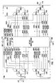
- Fig. 1 shows an optical switching node 400 for connection to other switching nodes in an optical network.
- the switching node 400 comprises a plurality of ports 402, 404, 406, 408 connected externally to a respective plurality of multi-wavelength optical fiber segments 412, 414, 416, 418.
- Optical fiber segments 412, 414, 416, 418 are bidirectional and serve both as ingress and egress links to neighbouring switching nodes (not shown).
- multiple optical fiber segments e.g., one for ingress and one for egress could connect the switching node 400 to each of its neighbours.
- Optical fiber segments 412, 414, 416, 418 preferably carry data to and from the neighbouring switching nodes.
- Optical fiber segments 412, 414, 416, 418 also preferably serve as control links between the neighbouring switching nodes by using dedicated supervisory wavelengths (known as an optical supervisory channel).
- dedicated supervisory wavelengths known as an optical supervisory channel.
- Other ways of establishing control links to the switching node include the use of dedicated electronic control lines.
- the switching node 400 can have any number of ports greater than or equal to two. Also, while optical fiber segments 412, 414, 416, 418 are intended to be connected between ports of neighbouring switching nodes, it should be understood that one or more of the optical fiber segments 412, 414, 416, 418 can be used for transporting individual or multiplexed optical channels to or from customer premises equipment. In this case, the switching node 400 would be referred to as an add/drop node.
- ports 402, 404, 406, 408 are connected to respective directional couplers 432, 434, 436, 438 by respective intermediate optical fiber segments 422, 424, 426, 428.
- Intermediate optical fiber segments 422, 424, 426, 428 are bidirectional and preferably carry both data and control signals to and from the inside of the switching node 400.
- the directional couplers 432, 434, 436, 438 are known components which couple two unidirectional multi-wavelength signals travelling in opposite directions to a single bidirectional multi-wavelength signal.
- each directional coupler 432, 434, 436, 438 retrieves incoming data and control signals carried on the respective intermediate optical fiber segment 422, 424, 426, 428 and feeds the incoming signals so retrieved to a respective optical demultiplexer 452, 454, 456, 458 along a respective intermediate optical fiber segment 442, 444, 446, 448.
- outgoing data and control signals are fed to the directional couplers 432, 434, 436, 438 by a respective optical multiplexer 552, 554, 556, 558 along a respective intermediate optical fiber segment 542, 544, 546, 548.
- Each directional coupler 432, 434, 436, 438 transfers the respective outgoing data and control signals onto the respective intermediate fiber optic segment 422, 424, 426, 428 connected to the respective port 402, 404, 406, 408.
- Each optical demultiplexer 452, 454, 456, 458 separates the multi-wavelength optical signal arriving on the respective intermediate optical fiber segment 442, 444, 446, 448 on the basis of wavelength to produce a respective set of individual optical signals appearing on a respective plurality of single-wavelength optical fiber segments 462A-D, 464A-D, 466A-D, 468A-D.
- Fig. 1 shows each of the optical demultiplexers 452, 454, 456, 458 as being associated with four single-wavelength optical fiber segments, it is to be understood that the number of segments emanating from an optical demultiplexer can correspond to the number of wavelengths in each multi-wavelength optical signal arriving at the respective optical demultiplexer along the respective intermediate optical fiber segment 442, 444, 446, 448.
- At least one of these will preferably be used for transporting control information and the remaining ones will preferably be used for transporting data to be switched.
- the transport of control information on a dedicated wavelength between two switching nodes is known as establishing an "out-of-band" control channel.
- an "in-band" control channel can be established by embedding a control-laden header within the data transported between two switching nodes, e.g., in a header portion.
- single-wavelength optical fiber segments 462A, 464A, 466A, 468A provide out-of-band control channels for carrying incoming control information from neighbouring switching nodes.
- Each single-wavelength optical fiber segment 462A, 464A, 466A, 468A is connected to a respective optoelectronic converter 472A, 474A, 476A, 478A.
- Each optoelectronic converter 472A, 474A, 476A, 478A converts the optical control signal on the respective single-wavelength optical fiber segment 462A, 464A, 466A, 468A into an electronic control signal on a respective input control line 482A, 484A, 486A, 488A.
- Input control lines 482A, 484A, 486A, 488A are connected to a controller 490.
- the remaining sets single-wavelength optical fiber segments 462B-D, 464B-D, 466B-D, 468B-D carry incoming data and each set is fed to a respective bank of controllable wavelength converters 472B-D, 474B-D, 476B-D, 478B-D.
- Each wavelength converter 472B-D, 474B-D, 476B-D, 478B-D is a device which translates the optical signal on the respective single-wavelength optical fiber segment 462B-D, 464B-D, 466B-D, 468B-D from its present wavelength onto a (possibly different) wavelength specified by a control signal sent by the controller 490 along a respective control line (not shown).
- wavelength conversion as performed by the wavelength converters 472B-D, 474B-D, 476B-D, 478B-D could be achieved via direct optical methods or by conversion into the electronic domain, followed by conversion back into the optical domain on another specified wavelength.
- each bank of wavelength converters 472B-D, 474B-D, 476B-D, 478B-D appear on a respective set of single-wavelength input optical fiber segments 462B'-D', 464B'-D', 466B'-D', 468B'-D' which are fed to respective input ports of an optical switch fabric 492.
- the optical switch fabric 492 also has a plurality of output ports connected to a respective plurality of single-wavelength output optical fiber segments 562B-D, 564B-D, 566B-D, 568B-D.
- the optical switch fabric 492 comprises circuitry for controllably establishing one-to-one optical connections between single-wavelength input optical fiber segments 462B'-D', 464B'-D', 466B'-D', 468B'-D' and single-wavelength output optical fiber segments 562B-D, 564B-D, 566B-D, 568B-D.
- the data connections are established on the basis of mapping instructions received from the controller 490 via a control line 494.
- the various intermediate optical fiber segments 442, 444, 446, 448, 542, 544, 546, 548 may accommodate differing numbers of wavelengths, the number of single-wavelength output optical fiber segments connected to the optical switch fabric 492 may differ from the number of single-wavelength input optical fiber segments connected thereto.
- the banks of wavelength converters could be connected to the single-wavelength output optical fiber segments 562B-D, 564B-D, 566B-D, 568B-D at the output of the optical switch fabric 492 rather than to the single-wavelength input optical fiber segments 462B'-D', 464B'-D', 466B'-D', 468B'-D' at the input of the optical switch fabric 492.
- a plurality of output control lines 582A, 584A, 586A, 588A emanating from the controller 490 form part of the respective out-of-band control channels linking the switching node 400 to neighbouring switching nodes.
- the output control lines 582A, 584A, 586A, 588A are respectively connected to a plurality of optoelectronic converters 572A, 574A, 576A, 578A.
- the optoelectronic converters 572A, 574A, 576A, 578A convert electronic control signals output by the controller 490 into optical signals appearing on respective single-wavelength optical fiber segments 562A, 564A, 566A, 568A.
- Each single-wavelength optical fiber segment 562A, 564A, 566A, 568A carrying outgoing control information from the controller 490 is connected to a respective one of the optical multiplexers 552, 554, 556, 558. Also leading to the optical multiplexers 552, 554, 556, 558 are respective sets of single-wavelength output optical fiber segments 562B-D, 564B-D, 566B-D, 568B-D carrying switched signals (i.e., outgoing data) from the optical switch fabric 492.
- the optical multiplexers 552, 554, 556, 558 combine the individual optical signals carried by respective groups of single-wavelength optical fiber segments 562A-D, 564A-D, 566A-D, 568A-D into respective multi-wavelength optical signals carried to respective directional couplers 432, 434, 436, 438 by respective intermediate optical fiber segments 542, 544, 546, 548.
- the controller 490 preferably comprises a processor 490A connected to a memory element 490B.
- the processor 490A is preferably a micro-processor running a software algorithm.
- the processor could be a digital signal processor or other programmable logic device.
- the memory element 490B stores wavelength availability information in the form of a wavelength availability table.
- Fig. 2A shows the structure of a wavelength availability table 700 in accordance with the preferred embodiment of the present invention.
- the wavelength availability table 700 comprises a PORT column 710, a WAVELENGTH column 720 and an AVAILABILITY column 730.
- the PORT column 710 contains one entry for each port in the switching node. In the case of the switching node 400 in Fig. 1, the number of ports, and therefore the number of entries in the PORT column 710 of the wavelength availability table 700, is equal to four.
- the ports are identified by their reference numerals from Fig. 1, namely 402, 404, 406 and 408.
- the WAVELENGTH column 720 For each row corresponding to a given port, there may be multiple entries in the WAVELENGTH column 720, depending on the number of wavelengths that can enter or exit the switching node through that port. For example, in the case of the switching node 400 in Fig. 1, there are six entries in the WAVELENGTH column 720 corresponding to each of the ports 402, 404, 406, 408. For each entry in the WAVELENGTH column 720, there is an entry in the AVAILABILITY column 730 indicating whether or not the corresponding wavelength is currently occupied on the corresponding port. A binary value is adequate for representing each entry in the AVAILABILITY column 730.
- the memory element 490B also stores topological information about the network. Specifically, the memory element 490B stores the identity of those switching nodes which are directly connected to switching node 400 via one of the optical fiber segments 412, 414, 416, 418. The memory element 490B also stores similar topological information about the rest of the network, which is transmitted to the switching node 400 by the neighbouring switching nodes.
- the processor 490A in the switching node 400 uses topological information stored in the memory element 490B to construct a topological tree of the entire network with the switching node 400 as the root. This tree is then used by the processor 490A to construct a routing table which is also stored in the memory element 490B.
- Fig. 2B illustrates the format of a routing table 600 in accordance with the preferred embodiment of the invention.
- the routing table 600 preferably contains four fields, namely a source switching node (SSN) field 610, a destination switching node (DSN) field 620, a traffic characteristic information (TCI) field 630 and a next hop switching node (NHSN) field 640.
- SSN source switching node
- DSN destination switching node
- TCI traffic characteristic information
- NHSN next hop switching node
- the entries in the SSN and DSN fields 610, 620 account for every possible combination of end switching nodes in the network.
- the TCI field 630 contains the traffic characteristic information received from the switching node identified by the entry in the DSN field 620 of the corresponding row in the routing table. In this way, the TCI field 630 identifies the signalling formats acceptable by the respective optical interface in each destination switching node.
- the switching node 400 will generally be one in a series of intermediate switching nodes located between source and destination.
- the next intermediate node along the route leading to the destination switching node is known as the next hop switching node and is identified in the NHSN field 640 of the routing table.
- the next hop switching node is a function of the source switching node, the destination switching node, the network topology and the position of the current switching node within that topology.
- the routing table is different for each switching node in the network and is basically static, changing only when the network undergoes a topological alteration.
- WR network-layer wavelength routing
- WD network-layer wavelength distribution
- Fig. 5 depicts an information propagation step 1010, an information storing step 1020 and an information processing step 1030.
- the propagation step 1010 consists of the controller 490 sending topology information and traffic characteristic information to neighbouring switching nodes via the appropriate control channel (either out-of-band or in-band).
- the topology information includes the identity of the switching node 400 and the identity of each switching node adjacent the switching node 400 and connected to one of its ports.
- the traffic characteristic information may consist of a listing of signalling types that are acceptable to each port. The contents of this listing may be governed by end user formatting requirements.
- the switching node 400 relays control information received from any neighbouring switching node to all other neighbouring switching nodes.
- the control information sent by the switching node 400 can be transmitted at regular intervals of, for instance, ten seconds or, alternatively, only when there is a change in the received control information.
- every switching node forwards not only its own control information but also that of its immediate neighbours, every switching node is recursively made aware of the topology of the entire network and of the acceptable signalling types associated with each switching node in the network.
- the storing step 1020 consists of the controller 490 storing, in the memory element 490B, its own topology and traffic characteristic information as well as that received from neighbouring switching nodes.
- the processing step 1030 consists of the controller 490 in the switching node 400 generating the routing table stored in the memory element 490B, either periodically or after a topology change, as a function of the network topology information and traffic characteristic information stored in the storing step 1020.
- the software in the processor of the switching node executes a next hop routing algorithm, for example the well-known Dijkstra algorithm. (See J. Moy , Network Working Group RFC 1583, pp. 142-160, hereby incorporated by reference herein). If the Dijkstra algorithm produces no suitable next hop switching node for a given row in the routing table 600, this fact can be signalled by leaving blank the corresponding entry in the NHSN and TCI fields 630, 640, respectively.
- the WD protocol is implemented by the processor in each switching node running an algorithm such as the one illustrated in the flowchart of Fig. 6.
- the inventive wavelength distribution (WD) protocol consists of the exchange and interpretation of several types of messages, including an INITIAL_CONNECTION_REQUEST message, a CONNECTION_REQUEST message, a CONNECTION_CONFIRM message and a CONNECTION_DENY message.
- the processor in a given switching node waits to receive a message.
- the processor verifies, at step 1620, whether it is an INITIAL_CONNECTION_REQUEST message.
- An INITIAL_CONNECTION_REQUEST message is typically generated by customer premises equipment connected to the source switching node, for example.
- the received message is indeed an INITIAL_CONNECTION_REQUEST message, then it will specify the source and destination switching nodes, as well as the signalling format (say, TCI s ) used by the interface connected to the source switching node.
- the processor verifies whether TCI s matches any one of the signalling formats accepted by the interface connected to the destination switching node. If there is no TCI match, then the source switching node customer is informed that a connection cannot be established.
- the processor looks up the entry in the NHSN field of the row of the routing table associated with the source and destination switching nodes and subsequently sends a CONNECTION_REQUEST message to the switching node identified by that entry.
- the CONNECTION_REQUEST message preferably contains a SSN parameter for identifying the source switching node and a DSN parameter for identifying the destination switching node.
- the intended recipient of the CONNECTION_REQUEST message is also known as the "next" switching node along the route between the source and destination nodes.
- the message found to be received at step 1620 might not be an INITIAL_CONNECTION_REQUEST message, but may be a CONNECTION_REQUEST message (such as the one sent by the source switching node after an INITIAL_CONNECTION_REQUEST message) .
- the CONNECTION_REQUEST message is assumed to be received by the current switching node from a "previous" switching node along the route between the source and destination switching nodes.
- step 1640 provides verifyication of whether there is a free wavelength between the previous switching node and the current switching node. If there is no such wavelength, then the processor causes a CONNECTION_DENY message to be sent to the previous switching node, as indicated at step 1650.
- step 1660 consists of storing this free wavelength in the memory element connected to the processor in the current switching node. This is followed by step 1670, at which it is verified whether the current switching node is in fact the destination switching node. If not, then, as indicated by step 1680, the CONNECTION_REQUEST message is forwarded to the next switching node along the route.
- step 1690 involves the establishment of a data connection through the optical switch fabric of the current switching node. This can be achieved by the controller 490 providing an appropriate mapping instruction to the optical switch fabric 492. This connection links the single-wavelength optical fiber associated with the free wavelength (as stored in the memory element after execution of step 1660) and the optical fiber segment leading to the customer premises equipment connected to the destination switching node.
- wavelength occupied by the customer premises equipment is different from the free wavelength stored in the memory element, then appropriate instructions must also be sent to the wavelength converter associated with the free wavelength. Furthermore, the wavelength availability table is updated to reflect that the "free" wavelength is no longer available on the corresponding port linking the current switching node with the previous switching node.
- step 1700 indicates that a CONNECTION_CONFIRM message is sent to the previous switching node, which is now optically connected to the current switching node by the free wavelength.
- the CONNECTION_CONFIRM message specifies the free wavelength.
- step 1620 if the received message is a CONNECTION_DENY message, then as indicated at step 1730, the action to be taken depends on whether the current switching node is the source switching node. If the current switching node is not the source switching node, then the CONNECTION_DENY message is backwarded to the previous switching node as indicated at step 1650. Thus, the CONNECTION_DENY message eventually reaches the source switching node where, according to step 1740, the customer is alerted to the fact that a connection cannot be established.
- the action to be taken again depends on whether the current switching node is the source switching node as indicated at step 1710. If the current switching node is indeed the source switching node, then a connection is established (step 1720) between the optical fiber segment connected to the customer premises equipment and the single-wavelength optical fiber segment carrying data between the source switching node and the next switching node.
- step 1690 a connection is established which joins the single-wavelength optical fiber segment carrying data between the current switching node and the previous and next switching nodes.
- the locally stored wavelength availability table is also updated to reflect the new wavelength occupancy on the optical fiber segment carrying data between the current switching node and the previous and next switching nodes. If necessary, wavelength conversion instructions are sent in either case to the appropriate wavelength converter. As shown at step 1700, a CONNECTION_CONFIRM message is subsequently sent to the previous switching node.
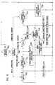
- FIG. 3 shows an optical network 800 comprising a plurality of switching nodes 802-824 connected in a meshed matrix pattern via a plurality of optical fiber segments 826-858.
- Switching node 802 is connected to customer premises equipment (CPE) 860 via an optical fiber segment 862 which uses a wavelength ⁇ S .
- the CPE 860 uses a signalling format which may be denoted TCI S .
- Switching node 824 is connected to CPE 864 via an optical fiber segment 866 which uses a wavelength ⁇ F .
- the CPE 864 accepts signalling formats which may be identified by the set ⁇ TCI F ⁇ .
- Fig. 7A shows part of a routing table 900 generated at switching node 802 corresponding to the row in which the source switching node is designated as switching node 802 and the destination switching node is designated as switching node 824.
- the entry in the TCI column 630 indicates that the CPE 864 connected to switching node 824 is capable of receiving data in the listed formats, namely OC-4, OC-32, OC-192 and Gigabit Ethernet (GBE).
- the entry in the NHSN column 640 indicates that the next hop switching node in the route joining switching nodes 802 and 824 is switching node 808.
- Fig. 7B shows an example row from a routing table 950 stored in the memory element of switching node 808.
- This row again corresponds to the source-destination combination involving switching nodes 802 and 824, respectively.
- the routing table 950 is generated from the perspective of switching node 808 and therefore the entries in the NHSN column 640 will be different from those in the routing table 900 stored in switching node 802.
- the entry in the NHSN column 640 specifies switching node 810.
- the corresponding entry in the NHSN column 640 in the routing tables stored in switching nodes 810, 816 and 818 can specify switching node 816, 818 and 824, respectively.
- switching node 802 and 824 consisting of optical fiber segments 830, 836, 842, 848 and 854 as indicated by the thick solid line in Fig. 3.
- potential routes exist between all other combinations of source switching node and destination switching node.
- switching node 802 compares the signalling format of CPE 860, namely TCI S , to the set of acceptable signalling formats associated with CPE 864, namely the set ⁇ TCI F ⁇ . If a TCI match is detected, then the processor in the source switching node 802 consults its routing table (Fig. 7A) and extracts the identity of the switching node in the NHSN field of the row corresponding to the particular source-destination switching node combination. In this case, the switching node so identified would be switching node 808. (It should be noted that if TCI S is not an element of the set ⁇ TCI F ⁇ , then the connection request is denied. As indicated in step 1740 of Fig. 6, the controller in the source switching node 802 may take action to alert the end user that the connection request has been denied.)
- the processor in the source switching node 802 then formulates a CONNECTION_REQUEST message for transmission to switching node 808 (step 1680).
- the CONNECTION_REQUEST message identified switching node 802 as the source switching node and switching node 824 as the destination switching node.
- the CONNECTION_REQUEST message is transmitted by the source switching node 802 to switching node 808 via the appropriate out-of-band or in-band control channel.
- switching node 808 consults its wavelength availability table to determine whether there is a free wavelength on the fiber optic segment 830 linking it to the previous switching node, in this case source switching node 802. Consequently, either a wavelength is found, in which case the wavelength request is further propagated along the route by forwarding a copy of the CONNECTION_REQUEST message to switching node 810 (step 1680), or a wavelength is not found, in which case the connection request is denied and a CONNECTION_DENY message is sent back to the source switching node 802 (step 1650). In this case, since switching node 808 is not the destination switching node 824, a connection is not yet established.
- the CONNECTION_DENY message is of a suitable format indicating that the connection request has been denied and the reasons therefor, in this case, an inability to find an available wavelength on fiber optic segment 830.
- the controller in the source switching node 802 may take action to alert the end user of CPE 860 that the connection request has been denied.
- Each of the switching nodes 810, 816, 818 runs the same algorithm and therefore performs essentially the same tasks as switching node 808. Hence, if wavelengths are available on each of fiber optic segments 836, 842 and 848, the CONNECTION_REQUEST message will eventually be received at the destination switching node 824. Similarly, a CONNECTION_DENY message returned to an one of the switching nodes 810, 816, 818 is relayed back to the source switching node 802, where action can be taken to alert the end user that a connection request has been denied.
- the CONNECTION_REQUEST message transmitted by the source switching node 802 will eventually reach the destination switching node 824 via "intermediate" switching nodes 808, 810, 816 and 818. Since it is identified by the DSN parameter in the CONNECTION_REQUEST message, the destination switching node 824 knows that it is the last switching node on the potential route leading from the source switching node 802. In the example scenario of Fig. 3, the final destination is CPE 864 which is connected to the destination switching node 824 via optical fiber segment 866 adapted to carry optical signals on wavelength ⁇ F . In response to the CONNECTION_REQUEST message, the processor in the destination switching node 824 attempts to find a free wavelength on optical fiber segment 854 connecting the destination switching node 824 with intermediate switching node 818.
- a data connection is established (step 1720). Specifically, the controller sends mapping instructions to its optical switch fabric for switching the optical signal on the single-wavelength input optical fiber segment associated with ⁇ I over to the optical fiber segment 866 leading to the customer premises equipment 864. In addition, the controller sends the value of the wavelength ⁇ F to the wavelength converter associated with the single-wavelength input optical fiber segment carrying the optical signal on wavelength ⁇ I . If ⁇ I is different from ⁇ F , that wavelength converter will be required to perform wavelength conversion. Furthermore, the destination switching node 824 updates its wavelength availability table with information about the newly established data connection. That is to say, the entry in the AVAILABILITY field 730 of the appropriate row is given a value indicating the fact that wavelength ⁇ I on optical fiber segment 854 is taken, i.e., unavailable.
- the WD protocol as described at step 1700 in Fig. 7 requires that the destination switching node 824 send a CONNECTION_CONFIRM message to the intermediate switching node 818.
- the CONNECTION_CONFIRM message specifies the wavelength ⁇ I , which is the wavelength (prior to wavelength conversion) associated with the single-wavelength input optical fiber segment connected through the optical switch fabric in the destination switching node 824.
- intermediate switching node 818 Upon receipt of the CONNECTION_CONFIRM message sent by the destination switching node 824, intermediate switching node 818 itself establishes a connection between the single-wavelength output optical fiber whose signal at wavelength ⁇ I is carried on optical fiber segment 854 and the single-wavelength input optical fiber 848 whose signal at the previously stored free wavelength (say, ⁇ J ) is carried on optical fiber segment 848. If ⁇ I does not equal ⁇ J , then the corresponding wavelength converter is instructed to perform the appropriate wavelength conversion. The controller in intermediate switching node 818 then updates its wavelength availability table and subsequently sends a CONNECTION_CONFIRM message to intermediate switching node 816. This message will specify ⁇ J (rather than ⁇ I or ⁇ F ).
- the controller in the source switching node 802 sends mapping instructions to its optical switch fabric with the aim of establishing a connection between the optical fiber segment 862 occupying wavelength ⁇ S connected to CPE 860 and the single-wavelength optical fiber segment whose signal is carried on a wavelength ⁇ K by optical fiber segment 830. If ⁇ K differs from ⁇ S , wavelength conversion commands are sent to the wavelength converter associated with optical fiber segment 862.
- the route between the source and destination switching nodes 802, 824 consisting of optical fiber segments 830, 836, 842, 848, 854 may occupy different wavelengths.
- the just described wavelength distribution (WD) protocol allows wavelengths to be assigned to specific optical fiber segments in a dynamic fashion each time a new connection is requested. Consequently, the available network bandwidth is used more efficiently and the time, effort and cost involved in configuring the switching nodes in the network are dramatically reduced.
- the client is connected to switching node 802 and that the server is connected to switching node 824.
- the client 802 is connected to CPE 860 via an optical fiber segment 862, while the server 824 is connected to a data base 864 via an optical fiber segment 866.
- the above-described WR protocol remains the mechanism by which the various switching nodes in the network exchange and process control information.
- the WD protocol is slightly modified.
- step 1630 in Fig. 6 may not be executable at the client switching node since the signalling type transmitted by the server may not be known. Therefore, this step must be postponed until a CONNECTION_REQUEST message is received at the server switching node, whereupon this step is performed by the server switching node.
- route selection is achieved by the switching nodes executing a routing control algorithm, it is possible for the source switching node or client to preselect the desired route through the network for particular combinations of end points.
- the NSHN entries in the routing table in each switching node can be pre-computed.
- Manual route pre-selection is also acceptable as there are advantages to be gained by having the wavelengths dynamically assigned along each segment in the route in accordance with the WD protocol.
- the WR protocol could simply be used for distributing and gathering traffic characteristic information, while omitting the processing step.
- Wavelength allocation for one direction of communication can follow the algorithm in the above source-destination scenario, while wavelength allocation for the reverse direction can follow the algorithm in the above-described client-server scenario.
- the invention extends to certain cases in which the signalling types at the end points do not match but are "compatible". For example, if the destination switching node accepts OC-48 signals but the source switching node transmits OC-12 signals, then either the end switching nodes or one of the intermediate switching nodes along the route between the two end switching nodes can be assigned the task of grooming the OC-12 signals so that they become OC-48 signals. In this case, OC-48 and OC-12 signalling types are said to be compatible.
- the WD protocol can be modified so that a CONNECTION_DENY message is sent if all wavelengths are unavailable or if TCI S is incompatible with every element of the set ⁇ TCI F ⁇ .
- compatibility may be determined by consulting a table of compatible pairs of signalling types which can be stored in the respective memory element.
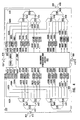
- FIG. 4 shows a switching node 900 in accordance with an alternative embodiment of the present invention.
- Switching node 900 is identical to switching node 400, except for certain differences which are now explained.
- Switching node 900 comprises groups of optoelectronic converters 902B-D, 904B-D, 906B-D, 908B-D connected between respective demultiplexers 452, 454, 456, 458 and a grooming processor and switch 992.
- Converters 902B-D, 904B-D, 906B-D, 908B-D are used for converting received optical data signals on respective single-wavelength input optical fibers 462B-D, 464B-D, 466B-D, 468B-D into electrical signals fed to the grooming processor 992.
- Analog-to-digital converters (not shown) are preferably provided between the optoelectronic converters 902B-D, 904B-D, 906B-D, 908B-D and the grooming processor and switch 992.
- the grooming processor and switch 992 is preferably a high-speed digital signal processor which is programmed to convert digital electronic signals from one signalling type to another.
- the grooming processor and switch 992 also provides a digital cross-connect facility for connecting each groomed electronic signal to any one of a plurality of electronic signal lines 962B-D, 964B-D, 966B-D, 968B-D.
- Groups of electronic signal lines 962B-D, 964B-D, 966B-D, 968B-D are connected to respective optical multiplexers 552, 554, 556, 558 via respective groups of optoelectronic converters 972B-D, 974B-D, 976B-D, 978B-D.
- the optoelectronic converters convert the respective electronic signals into optical signals at a wavelength controllable from the controller 490 via respective control lines (not shown). For this reason, wavelength converters are not explicitly required in the design of the switching node in Fig. 4, since their functionality is implicit in the optoelectronic converters 972B-D, 974B-D, 976B-D, 978B-D.
- the switching nodes in Fig. 1 and 4 and the WR and WD protocols governing their behaviour can be used to implement a reliable protection facility in a meshed network. More specifically, if a data connection is established over a particular fiber optic link and if that link fails, then a new data connection request can be initiated by the source switching node. Since each switching node participates in the WR protocol, the change in the topology of the network resulting from the broken link will automatically result in different values for the NHSN column in the respective routing tables.
- a new connection request can be programmed to occur after a failure is detected, which request is handled by the WD protocol of the present invention, resulting in a new and reliable route for the originally disrupted data connection.
- Further advantages of relying on the WR and WD protocols described herein include wavelength efficiency, since protection wavelengths need not be dedicated in advance, as well as independent re-routing for different wavelengths occupied by a single optical fiber segment. This latter feature is advantageous because it allows the protection of individual wavelengths wherever there is capacity in the network.
- an all-optical switching fabric similar to the switch fabric 492 in Fig. 1.
- the switch fabric can be made responsive to switching instructions for a particular input optical signal that vary as a function of time.
- This functionality can be useful in situations where the nature of the input optical signal is packet-based, with each packet having a header portion and a payload portion.
- the header may identify the source and destination switching nodes. Although different packets share the same wavelength and the same single-wavelength optical fiber segment, their associated headers may indicate an entirely different source and/or destination.
- the switching node could thus comprise a bank of optical taps (e.g., PIN diodes) connected to the single-wavelength input optical fiber segments. These taps would be connected to optoelectronic converters, which would all be connected to the controller. The header of each incoming packet could thus be read and processed by the controller.
- optical taps e.g., PIN diodes
- the wavelength routing (WR) protocol functions as previously described. Furthermore, once a data connection request is made, in which a respective source-destination pair is identified, a specific set of mapping instructions and wavelength conversion commands are generated using the wavelength distribution (WD) protocol, based on the network topology.
- an additional step is performed before mapping the single-wavelength input optical fiber segment to the single-wavelength output optical fiber segment in order to establish a particular data connection. Specifically, the header of each packet on the input optical fiber segment is examined. It is only if the source and destination specified in the header match the source-destination pair for which a connection has been prepared using the WD protocol that the previously derived mapping instructions and wavelength conversion commands are used.
- mappings it is also within the scope of the invention to allow multiple mappings to be associated with each single-wavelength input optical fiber segment, with a single mapping being applied for each packet, depending on the source and destination switching nodes specified in the header.
Abstract
Description
- The present invention relates to the field of optical switching in general and, more particularly, to optical switching nodes for use in an optical network. The invention also pertains to protocols governing the behaviour of the switching nodes.
- The development of high-capacity networks has been driven by the need to establish high-bandwidth data connections among remote sites, for instance, between clients and servers. Most often, the communications infrastructure for such a network is provided by one or more long-distance carriers serving the geographic region that encompasses the various remote sites. A carrier may lease fiber optic lines to customers wishing to establish high-capacity connections. Within the carrier's network, optical switching nodes are then configured to support the desired connections.
- Usually, a carrier leases its fiber optic lines with a view to long-term usage thereof. Thus, switch configurations established at the time of provisioning the high-capacity connections are expected to remain in place for a period of months or years. Therefore, the switches in the network can be configured manually with virtually no impact on cost or quality of service provided.
- However, it is not feasible to manually configure a large number of switches when dealing with a network whose size and/or topology are in constant evolution. Furthermore, the manual configuration of switches cannot accommodate situations in which the bandwidth or quality of service requirements of the traffic to be transported through the network is time-varying or if there is urgency in establishing new high-capacity connections through the network. Although it is desirable to provide switches which are automatically reconfigurable as a function of changes to the topology and traffic load of the network, such a capability is currently not available.
- Moreover, the most common approach to establishing end-to-end data connections in current optical networks relies on the utilization of the same wavelength, say λx, along a manually configured path throughout the network. This prevents the establishment of other data connections using λx as an end-to-end wavelength if part of the path corresponding to the new connection intersects part of the path corresponding to the original connection. This places a severe constraint on wavelength usage in a current optical network, with the effect of drastically reducing the overall bandwidth efficiency in the network.
- Thus, it is apparent that there is a need in the industry to provide an optical switching node which overcomes the above stated disadvantages.
- The invention can be described broadly as a switching node that includes an optical switch fabric, a wavelength conversion unit and a control unit. The optical switch fabric is connected to the control unit and is used for switching optical signals arriving on a set of input optical fiber segments over to a set of output optical fiber segments in accordance with mapping instructions received from the control unit. The wavelength conversion unit is connected to the optical switch fabric and is used for modifying the wavelengths occupied by incoming or switched optical signals in accordance with conversion commands received from the control unit.
- The control unit is used for exchanging control information with other switching nodes using a network layer protocol and generating the mapping instructions and the conversion commands based on this control information. This switching node allows the input and output wavelengths of an optical data signal to occupy different wavelengths, which provides many benefits, among which is included the benefit of increased wavelength efficiency in an optical network.
- Preferably, the control information is exchanged using a out-of-band control channel such as an optical supervisory channel.
- Preferably, the control unit includes a processor and a memory element accessible by the processor. The memory element preferably stores a routing table and a wavelength availability table. The routing table contains a next hop switching node field associated with every possible pair of terminal switching nodes. The wavelength availability table contains the identity of the switching nodes connected to any of the ports by a respective multi-wavelength fiber optic link and, for each wavelength, an indication of whether that wavelength is occupied or available.
- The switching node is most often connected to a previous switching node in a path identified by a first terminal switching node and a second terminal switching node. In such a scenario, the control unit is preferably operable to receive messages from the previous switching node.
- If the message is a so-called CONNECTION_REQUEST message, then the control unit will preferably access the wavelength availability table to identify an available wavelength on the link between the current and previous switching nodes, the available wavelength being associated with one of the input optical fiber segments.
- If the current switching node is the second terminal switching node, then the control unit will preferably generate mapping commands for establishing a connection, using the available wavelength, between the input optical fiber segment associated with the available wavelength and one of the output optical fiber segments; and send a CONNECTION_CONFIRM message to the previous switching node.
- Otherwise, if the current switching node is not the second terminal switching node, the control unit will preferably access the routing table to determine the contents of the next hop switching node field associated with the first and second terminal switching nodes; and forward the CONNECTION_REQUEST message to the switching node identified by the next hop switching node field.
- If, on the other hand, the message is a so-called CONNECTION_CONFIRM message, then the control unit will preferably generate mapping commands for establishing a connection using the available wavelength between the input optical fiber segment associated with the available wavelength and one of the output optical fiber segments; and send a CONNECTION_CONFIRM message to the previous switching node.
- In order to accommodate a packet-based architecture, in which incoming optical signals are formed of packets having a header and a payload, the switching node may include an additional conversion unit connected to the input optical fiber segments and to the control unit, for extracting the header of each packet. In this case, the mapping instructions and the conversion commands generated by the controller will further be dependent on the information contained in the header of each packet.
- In another embodiment, the switching node includes a first set of optoelectronic converters and a second set of optoelectronic converters. The first set of converters is used for converting input optical signals occupying respective wavelengths into electronic signals, while the second set of converters is used for converting output electronic signals into output optical signals occupying respective wavelengths.
- The switching node also includes a digital switch fabric connected to the optoelectronic converters, for switching the input electronic signals over to the output electronic signals in accordance with switching instructions. Finally, the switching node includes a control unit connected to the digital switch fabric and to the optoelectronic converters. The control unit exchanges control information with other switching nodes using a network layer protocol and generates the switching instructions based on the control information.
- In this embodiment, the switching node provides grooming functionality in the sense that the input electronic signals can be reformatted so that when these reformatted signals are switched and then converted into an optical format by the second set of converters, the resulting optical signal can be in a desired format. This improves compatibility among end user equipment in a network.
- The invention may be summarized at the network level as a method of establishing a data connection between first and second terminal switching nodes. The network is understood to include the terminal switching nodes as well as a group of other switching nodes interconnected by multi-wavelength optical links.
- The method includes a first step of identifying a path comprising a set of links and wavelengths for transporting data between the first and second terminal switching nodes via zero or more intermediate switching nodes.
- The method also includes the step of, at each intermediate switching node connected to a respective ingress link and a respective egress link in the identified path, switching the optical signals arriving on the respective ingress link over to the respective egress link and performing wavelength conversion if the wavelengths occupied on the respective ingress and egress links are different.
Advantageously, this allows a data connection to be established using different wavelengths along the way. - The invention can also be summarized as a wavelength distribution protocol for enabling a data connection to be established between a first terminal switching node and a second terminal switching node via zero or more intermediate switching nodes along a path in a network. The protocol is executed at the various switching nodes in the network.
- At each current switching node connected in the path between a previous switching node and/or a next switching node by respective optical links, the protocol includes the capability to receive messages from the previous or next switching node.
- If the message is a CONNECTION_REQUEST message, then if the current switching node is not the first terminal switching node, the protocol includes identifying and storing an available wavelength on the link between the current and previous switching nodes.
- Also, if the message is a CONNECTION_REQUEST message and if the current switching node is indeed the second terminal switching node, the protocol includes establishing a connection using the available wavelength and sending a CONNECTION_CONFIRM message to the previous switching node, otherwise forwarding the CONNECTION_REQUEST message to the next switching node.
- If, however, the message is a CONNECTION_CONFIRM message, then the protocol includes establishing a connection using the previously stored available wavelength and if the current switching node is not the first terminal switching node, sending a CONNECTION_CONFIRM message to the previous switching node.
- For the protocol to operate as intended, an initial CONNECTION_REQUEST message is assumed to be sent to the first terminal switching node upon initially requesting the data connection.
- By participating in this protocol, switching nodes automatically participate in the end-to-end establishment of data connections using dynamically assigned wavelengths, which improves overall bandwidth efficiency of the optical network and provides more flexible protection switching, which no longer requires the input and output wavelengths to be identical.
- These and other aspects and features of the present invention will become apparent to persons skilled in the art upon review of the following description of specific embodiments of the invention in conjunction with the accompanying drawings, in which:
- Fig. 1 illustrates in schematic form a switching node in accordance with the preferred embodiment of the present invention;
- Fig. 2A shows a possible structure of a wavelength availability table created by the controller in the switching node of Fig. 1;
- Fig. 2B shows a possible structure of a routing table created by the controller in the switching node of Fig. 1;
- Fig. 3 illustrates in schematic form an optical network and a route linking two switching nodes in the network;
- Fig. 4 illustrates in schematic form a switching node in accordance with an alternative embodiment of the present invention;
- Fig. 5 shows a flowchart illustrating an inventive wavelength routing protocol;
- Fig. 6 shows a flowchart illustrating an inventive wavelength distribution protocol; and
- Figs. 7A and 7B illustrate routing table entries for two switching nodes along the route in Fig. 3.
-
- Fig. 1 shows an
optical switching node 400 for connection to other switching nodes in an optical network. According to the preferred embodiment of the present invention, the switchingnode 400 comprises a plurality ofports optical fiber segments Optical fiber segments node 400 to each of its neighbours. -
Optical fiber segments Optical fiber segments - Although depicted as having four ports, the switching
node 400 can have any number of ports greater than or equal to two. Also, whileoptical fiber segments optical fiber segments node 400 would be referred to as an add/drop node. - Within the switching
node 400,ports directional couplers optical fiber segments optical fiber segments node 400. Thedirectional couplers - In one direction, each
directional coupler optical fiber segment optical demultiplexer optical fiber segment - In the opposite direction, outgoing data and control signals are fed to the
directional couplers optical multiplexer optical fiber segment directional coupler fiber optic segment respective port - Each
optical demultiplexer optical fiber segment optical fiber segments 462A-D, 464A-D, 466A-D, 468A-D. - Although Fig. 1 shows each of the
optical demultiplexers optical fiber segment - Among the plurality of single-wavelength optical fiber segments emanating from each demultiplexer, at least one of these will preferably be used for transporting control information and the remaining ones will preferably be used for transporting data to be switched. The transport of control information on a dedicated wavelength between two switching nodes is known as establishing an "out-of-band" control channel. Alternatively, an "in-band" control channel can be established by embedding a control-laden header within the data transported between two switching nodes, e.g., in a header portion.
- In the specific case of Fig. 1, single-wavelength
optical fiber segments optical fiber segment optoelectronic converter optoelectronic converter optical fiber segment input control line Input control lines controller 490. - The remaining sets single-wavelength
optical fiber segments 462B-D, 464B-D, 466B-D, 468B-D carry incoming data and each set is fed to a respective bank ofcontrollable wavelength converters 472B-D, 474B-D, 476B-D, 478B-D. Eachwavelength converter 472B-D, 474B-D, 476B-D, 478B-D is a device which translates the optical signal on the respective single-wavelengthoptical fiber segment 462B-D, 464B-D, 466B-D, 468B-D from its present wavelength onto a (possibly different) wavelength specified by a control signal sent by thecontroller 490 along a respective control line (not shown). - It should be appreciated that wavelength conversion as performed by the
wavelength converters 472B-D, 474B-D, 476B-D, 478B-D could be achieved via direct optical methods or by conversion into the electronic domain, followed by conversion back into the optical domain on another specified wavelength. - The signals converted by each bank of
wavelength converters 472B-D, 474B-D, 476B-D, 478B-D appear on a respective set of single-wavelength inputoptical fiber segments 462B'-D', 464B'-D', 466B'-D', 468B'-D' which are fed to respective input ports of anoptical switch fabric 492. - The
optical switch fabric 492 also has a plurality of output ports connected to a respective plurality of single-wavelength outputoptical fiber segments 562B-D, 564B-D, 566B-D, 568B-D. Theoptical switch fabric 492 comprises circuitry for controllably establishing one-to-one optical connections between single-wavelength inputoptical fiber segments 462B'-D', 464B'-D', 466B'-D', 468B'-D' and single-wavelength outputoptical fiber segments 562B-D, 564B-D, 566B-D, 568B-D. The data connections are established on the basis of mapping instructions received from thecontroller 490 via acontrol line 494. - Those skilled in the art will appreciate that because the various intermediate
optical fiber segments optical switch fabric 492 may differ from the number of single-wavelength input optical fiber segments connected thereto. - It will also be understood that the banks of wavelength converters could be connected to the single-wavelength output
optical fiber segments 562B-D, 564B-D, 566B-D, 568B-D at the output of theoptical switch fabric 492 rather than to the single-wavelength inputoptical fiber segments 462B'-D', 464B'-D', 466B'-D', 468B'-D' at the input of theoptical switch fabric 492. - A plurality of
output control lines controller 490 form part of the respective out-of-band control channels linking the switchingnode 400 to neighbouring switching nodes. Theoutput control lines optoelectronic converters optoelectronic converters controller 490 into optical signals appearing on respective single-wavelengthoptical fiber segments - Each single-wavelength
optical fiber segment controller 490 is connected to a respective one of theoptical multiplexers optical multiplexers optical fiber segments 562B-D, 564B-D, 566B-D, 568B-D carrying switched signals (i.e., outgoing data) from theoptical switch fabric 492. Theoptical multiplexers optical fiber segments 562A-D, 564A-D, 566A-D, 568A-D into respective multi-wavelength optical signals carried to respectivedirectional couplers optical fiber segments - The
controller 490 preferably comprises aprocessor 490A connected to amemory element 490B. Theprocessor 490A is preferably a micro-processor running a software algorithm. Alternatively, the processor could be a digital signal processor or other programmable logic device. - The
memory element 490B stores wavelength availability information in the form of a wavelength availability table. Fig. 2A shows the structure of a wavelength availability table 700 in accordance with the preferred embodiment of the present invention. The wavelength availability table 700 comprises aPORT column 710, aWAVELENGTH column 720 and anAVAILABILITY column 730. ThePORT column 710 contains one entry for each port in the switching node. In the case of the switchingnode 400 in Fig. 1, the number of ports, and therefore the number of entries in thePORT column 710 of the wavelength availability table 700, is equal to four. The ports are identified by their reference numerals from Fig. 1, namely 402, 404, 406 and 408. - For each row corresponding to a given port, there may be multiple entries in the
WAVELENGTH column 720, depending on the number of wavelengths that can enter or exit the switching node through that port. For example, in the case of the switchingnode 400 in Fig. 1, there are six entries in theWAVELENGTH column 720 corresponding to each of theports WAVELENGTH column 720, there is an entry in theAVAILABILITY column 730 indicating whether or not the corresponding wavelength is currently occupied on the corresponding port. A binary value is adequate for representing each entry in theAVAILABILITY column 730. - The
memory element 490B also stores topological information about the network. Specifically, thememory element 490B stores the identity of those switching nodes which are directly connected to switchingnode 400 via one of theoptical fiber segments memory element 490B also stores similar topological information about the rest of the network, which is transmitted to the switchingnode 400 by the neighbouring switching nodes. Theprocessor 490A in the switchingnode 400 uses topological information stored in thememory element 490B to construct a topological tree of the entire network with the switchingnode 400 as the root. This tree is then used by theprocessor 490A to construct a routing table which is also stored in thememory element 490B. - Fig. 2B illustrates the format of a routing table 600 in accordance with the preferred embodiment of the invention. The routing table 600 preferably contains four fields, namely a source switching node (SSN)
field 610, a destination switching node (DSN)field 620, a traffic characteristic information (TCI)field 630 and a next hop switching node (NHSN)field 640. - The entries in the SSN and
DSN fields TCI field 630 contains the traffic characteristic information received from the switching node identified by the entry in theDSN field 620 of the corresponding row in the routing table. In this way, theTCI field 630 identifies the signalling formats acceptable by the respective optical interface in each destination switching node. - Typically, it will not be possible to send data from a source switching node to a destination switching node without passing through at least one intermediate switching node. Thus, the switching
node 400 will generally be one in a series of intermediate switching nodes located between source and destination. The next intermediate node along the route leading to the destination switching node is known as the next hop switching node and is identified in theNHSN field 640 of the routing table. The next hop switching node is a function of the source switching node, the destination switching node, the network topology and the position of the current switching node within that topology. Thus, the routing table is different for each switching node in the network and is basically static, changing only when the network undergoes a topological alteration. - In operation, the manner in which control information is communicated and interpreted by the various switching nodes in the network is governed by a network-layer wavelength routing (WR) protocol. An end-to-end path for transferring data from a source switching node to a destination switching node along a path in a network can be established by having each switching node participate in a network-layer wavelength distribution (WD) protocol. Both protocols are now described.
- The WR protocol is implemented by having the processor in each switching node run an algorithm such as the one illustrated in the flowchart of Fig. 5. Specifically, Fig. 5 depicts an
information propagation step 1010, aninformation storing step 1020 and aninformation processing step 1030. - Firstly, the
propagation step 1010 consists of thecontroller 490 sending topology information and traffic characteristic information to neighbouring switching nodes via the appropriate control channel (either out-of-band or in-band). The topology information includes the identity of the switchingnode 400 and the identity of each switching node adjacent the switchingnode 400 and connected to one of its ports. The traffic characteristic information may consist of a listing of signalling types that are acceptable to each port. The contents of this listing may be governed by end user formatting requirements. - In addition, as another part of the
propagation step 1010, the switchingnode 400 relays control information received from any neighbouring switching node to all other neighbouring switching nodes. The control information sent by the switchingnode 400 can be transmitted at regular intervals of, for instance, ten seconds or, alternatively, only when there is a change in the received control information. - It is noted that because each switching node forwards not only its own control information but also that of its immediate neighbours, every switching node is recursively made aware of the topology of the entire network and of the acceptable signalling types associated with each switching node in the network.
- The storing
step 1020 consists of thecontroller 490 storing, in thememory element 490B, its own topology and traffic characteristic information as well as that received from neighbouring switching nodes. - Finally, the
processing step 1030 consists of thecontroller 490 in the switchingnode 400 generating the routing table stored in thememory element 490B, either periodically or after a topology change, as a function of the network topology information and traffic characteristic information stored in thestoring step 1020. With reference to the routing table shown in Fig. 2B, in order to fill theNHSN field 640 for a particular row in the routing table 600, the software in the processor of the switching node executes a next hop routing algorithm, for example the well-known Dijkstra algorithm. (See J. Moy, Network Working Group RFC 1583, pp. 142-160, hereby incorporated by reference herein). If the Dijkstra algorithm produces no suitable next hop switching node for a given row in the routing table 600, this fact can be signalled by leaving blank the corresponding entry in the NHSN andTCI fields - The WD protocol is implemented by the processor in each switching node running an algorithm such as the one illustrated in the flowchart of Fig. 6. The inventive wavelength distribution (WD) protocol consists of the exchange and interpretation of several types of messages, including an INITIAL_CONNECTION_REQUEST message, a CONNECTION_REQUEST message, a CONNECTION_CONFIRM message and a CONNECTION_DENY message.
- Referring to the flowchart in Fig. 6 and, more specifically, to step 1610, the processor in a given switching node waits to receive a message. Upon receipt of a message the processor verifies, at
step 1620, whether it is an INITIAL_CONNECTION_REQUEST message. An INITIAL_CONNECTION_REQUEST message is typically generated by customer premises equipment connected to the source switching node, for example. - If the received message is indeed an INITIAL_CONNECTION_REQUEST message, then it will specify the source and destination switching nodes, as well as the signalling format (say, TCIs) used by the interface connected to the source switching node. At
step 1630, the processor verifies whether TCIs matches any one of the signalling formats accepted by the interface connected to the destination switching node. If there is no TCI match, then the source switching node customer is informed that a connection cannot be established. - On the other hand, if there is a TCI match, then the processor looks up the entry in the NHSN field of the row of the routing table associated with the source and destination switching nodes and subsequently sends a CONNECTION_REQUEST message to the switching node identified by that entry. The CONNECTION_REQUEST message preferably contains a SSN parameter for identifying the source switching node and a DSN parameter for identifying the destination switching node. The intended recipient of the CONNECTION_REQUEST message is also known as the "next" switching node along the route between the source and destination nodes.
- The message found to be received at
step 1620 might not be an INITIAL_CONNECTION_REQUEST message, but may be a CONNECTION_REQUEST message (such as the one sent by the source switching node after an INITIAL_CONNECTION_REQUEST message) . The CONNECTION_REQUEST message is assumed to be received by the current switching node from a "previous" switching node along the route between the source and destination switching nodes. - In the event that a CONNECTION_REQUEST message was received,
step 1640 provides verifyication of whether there is a free wavelength between the previous switching node and the current switching node. If there is no such wavelength, then the processor causes a CONNECTION_DENY message to be sent to the previous switching node, as indicated atstep 1650. - On the other hand, if there is a free wavelength, then step 1660 consists of storing this free wavelength in the memory element connected to the processor in the current switching node. This is followed by
step 1670, at which it is verified whether the current switching node is in fact the destination switching node. If not, then, as indicated bystep 1680, the CONNECTION_REQUEST message is forwarded to the next switching node along the route. - If, however, the current switching node is indeed the destination switching node, then step 1690 involves the establishment of a data connection through the optical switch fabric of the current switching node. This can be achieved by the
controller 490 providing an appropriate mapping instruction to theoptical switch fabric 492. This connection links the single-wavelength optical fiber associated with the free wavelength (as stored in the memory element after execution of step 1660) and the optical fiber segment leading to the customer premises equipment connected to the destination switching node. - If the wavelength occupied by the customer premises equipment is different from the free wavelength stored in the memory element, then appropriate instructions must also be sent to the wavelength converter associated with the free wavelength. Furthermore, the wavelength availability table is updated to reflect that the "free" wavelength is no longer available on the corresponding port linking the current switching node with the previous switching node.
- After a connection has been established,
step 1700 indicates that a CONNECTION_CONFIRM message is sent to the previous switching node, which is now optically connected to the current switching node by the free wavelength. The CONNECTION_CONFIRM message specifies the free wavelength. - Returning now to step 1620, if the received message is a CONNECTION_DENY message, then as indicated at
step 1730, the action to be taken depends on whether the current switching node is the source switching node. If the current switching node is not the source switching node, then the CONNECTION_DENY message is backwarded to the previous switching node as indicated atstep 1650. Thus, the CONNECTION_DENY message eventually reaches the source switching node where, according to step 1740, the customer is alerted to the fact that a connection cannot be established. - Finally, if the message found to be received at
step 1620 is a CONNECTION_CONFIRM message, then the action to be taken again depends on whether the current switching node is the source switching node as indicated atstep 1710. If the current switching node is indeed the source switching node, then a connection is established (step 1720) between the optical fiber segment connected to the customer premises equipment and the single-wavelength optical fiber segment carrying data between the source switching node and the next switching node. - Otherwise (step 1690), a connection is established which joins the single-wavelength optical fiber segment carrying data between the current switching node and the previous and next switching nodes. In addition, the locally stored wavelength availability table is also updated to reflect the new wavelength occupancy on the optical fiber segment carrying data between the current switching node and the previous and next switching nodes. If necessary, wavelength conversion instructions are sent in either case to the appropriate wavelength converter. As shown at
step 1700, a CONNECTION_CONFIRM message is subsequently sent to the previous switching node. - An example illustrating how an end-to-end connection is prepared using the WD protocol is now described with reference to Fig. 3, which shows an
optical network 800 comprising a plurality of switching nodes 802-824 connected in a meshed matrix pattern via a plurality of optical fiber segments 826-858.Switching node 802 is connected to customer premises equipment (CPE) 860 via an optical fiber segment 862 which uses a wavelength λS. TheCPE 860 uses a signalling format which may be denoted TCIS.Switching node 824 is connected toCPE 864 via an optical fiber segment 866 which uses a wavelength λF. TheCPE 864 accepts signalling formats which may be identified by the set {TCIF}. - The switching nodes 802-824 participate in the inventive WR protocol. Thus, a routing table will be generated at each switching node. This routing table is different for each switching node but is static until the topology of the network changes. For purposes of illustration and without loss of generality, Fig. 7A shows part of a routing table 900 generated at switching
node 802 corresponding to the row in which the source switching node is designated as switchingnode 802 and the destination switching node is designated as switchingnode 824. Specifically, the entry in theTCI column 630 indicates that theCPE 864 connected to switchingnode 824 is capable of receiving data in the listed formats, namely OC-4, OC-32, OC-192 and Gigabit Ethernet (GBE). The entry in theNHSN column 640 indicates that the next hop switching node in the route joining switchingnodes node 808. - Similarly, Fig. 7B shows an example row from a routing table 950 stored in the memory element of switching
node 808. This row again corresponds to the source-destination combination involving switchingnodes node 808 and therefore the entries in theNHSN column 640 will be different from those in the routing table 900 stored in switchingnode 802. In the example of Fig. 7B, the entry in theNHSN column 640 specifies switchingnode 810. Similarly, the corresponding entry in theNHSN column 640 in the routing tables stored in switchingnodes node - Thus, a potential route exists between switching
node optical fiber segments - The messaging scheme of the WD protocol is now illustrated with continued reference to the network of Fig. 3 and the flowchart of Fig. 6. Firstly, the desire to establish an end-to-end data connection between
CPE 860 andCPE 864 is signalled to thesource switching node 802 in any suitable way. That is to say, an INITIAL_CONNECTION_REQUEST message is received by switchingnode 802. - In accordance with the WD protocol (at step 1630), switching
node 802 compares the signalling format ofCPE 860, namely TCIS, to the set of acceptable signalling formats associated withCPE 864, namely the set {TCIF}. If a TCI match is detected, then the processor in thesource switching node 802 consults its routing table (Fig. 7A) and extracts the identity of the switching node in the NHSN field of the row corresponding to the particular source-destination switching node combination. In this case, the switching node so identified would be switchingnode 808. (It should be noted that if TCIS is not an element of the set {TCIF}, then the connection request is denied. As indicated in step 1740 of Fig. 6, the controller in thesource switching node 802 may take action to alert the end user that the connection request has been denied.) - The processor in the
source switching node 802 then formulates a CONNECTION_REQUEST message for transmission to switching node 808 (step 1680). The CONNECTION_REQUEST message identified switchingnode 802 as the source switching node and switchingnode 824 as the destination switching node. The CONNECTION_REQUEST message is transmitted by thesource switching node 802 to switchingnode 808 via the appropriate out-of-band or in-band control channel. - In accordance with
step 1640 of Fig. 6, switchingnode 808 consults its wavelength availability table to determine whether there is a free wavelength on the fiber optic segment 830 linking it to the previous switching node, in this casesource switching node 802. Consequently, either a wavelength is found, in which case the wavelength request is further propagated along the route by forwarding a copy of the CONNECTION_REQUEST message to switching node 810 (step 1680), or a wavelength is not found, in which case the connection request is denied and a CONNECTION_DENY message is sent back to the source switching node 802 (step 1650). In this case, since switchingnode 808 is not thedestination switching node 824, a connection is not yet established. - If sent, the CONNECTION_DENY message is of a suitable format indicating that the connection request has been denied and the reasons therefor, in this case, an inability to find an available wavelength on fiber optic segment 830. According to
steps 1730 and 1740 of Fig. 6, upon receipt of a CONNECTION_DENY message, the controller in thesource switching node 802 may take action to alert the end user ofCPE 860 that the connection request has been denied. - Each of the switching
nodes node 808. Hence, if wavelengths are available on each offiber optic segments destination switching node 824. Similarly, a CONNECTION_DENY message returned to an one of the switchingnodes source switching node 802, where action can be taken to alert the end user that a connection request has been denied. - Assuming that TCIS belongs to the set {TCIF} and that a suitable wavelength path is available, the CONNECTION_REQUEST message transmitted by the
source switching node 802 will eventually reach thedestination switching node 824 via "intermediate" switchingnodes destination switching node 824 knows that it is the last switching node on the potential route leading from thesource switching node 802. In the example scenario of Fig. 3, the final destination isCPE 864 which is connected to thedestination switching node 824 via optical fiber segment 866 adapted to carry optical signals on wavelength λF. In response to the CONNECTION_REQUEST message, the processor in thedestination switching node 824 attempts to find a free wavelength on optical fiber segment 854 connecting thedestination switching node 824 withintermediate switching node 818. - If such a wavelength is found, say λI, then a data connection is established (step 1720). Specifically, the controller sends mapping instructions to its optical switch fabric for switching the optical signal on the single-wavelength input optical fiber segment associated with λI over to the optical fiber segment 866 leading to the
customer premises equipment 864. In addition, the controller sends the value of the wavelength λF to the wavelength converter associated with the single-wavelength input optical fiber segment carrying the optical signal on wavelength λI. If λI is different from λF, that wavelength converter will be required to perform wavelength conversion. Furthermore, thedestination switching node 824 updates its wavelength availability table with information about the newly established data connection. That is to say, the entry in theAVAILABILITY field 730 of the appropriate row is given a value indicating the fact that wavelength λI on optical fiber segment 854 is taken, i.e., unavailable. - After instructing its optical switch fabric to set up a data connection, the WD protocol as described at
step 1700 in Fig. 7 requires that thedestination switching node 824 send a CONNECTION_CONFIRM message to theintermediate switching node 818. The CONNECTION_CONFIRM message specifies the wavelength λI, which is the wavelength (prior to wavelength conversion) associated with the single-wavelength input optical fiber segment connected through the optical switch fabric in thedestination switching node 824. - Upon receipt of the CONNECTION_CONFIRM message sent by the
destination switching node 824,intermediate switching node 818 itself establishes a connection between the single-wavelength output optical fiber whose signal at wavelength λI is carried on optical fiber segment 854 and the single-wavelength input optical fiber 848 whose signal at the previously stored free wavelength (say, λJ) is carried on optical fiber segment 848. If λI does not equal λJ, then the corresponding wavelength converter is instructed to perform the appropriate wavelength conversion. The controller inintermediate switching node 818 then updates its wavelength availability table and subsequently sends a CONNECTION_CONFIRM message tointermediate switching node 816. This message will specify λJ (rather than λI or λF). - Backtracking of the CONNECTION_CONFIRM message continues until this message is received at the
source switching node 802. According to step 1720 of the algorithm described with reference to Fig. 7, the controller in thesource switching node 802 sends mapping instructions to its optical switch fabric with the aim of establishing a connection between the optical fiber segment 862 occupying wavelength λS connected toCPE 860 and the single-wavelength optical fiber segment whose signal is carried on a wavelength λK by optical fiber segment 830. If λK differs from λS, wavelength conversion commands are sent to the wavelength converter associated with optical fiber segment 862. - From the above, it is seen that the route between the source and
destination switching nodes optical fiber segments - While the above description of the WD protocol has dealt with the case in which a source switching node wishes to unilaterally send data to a destination switching node, the present invention also applies to the case in which one switching node wishes to extract data from another. In this reverse unidirectional situation, it is more appropriate to call the two end switching nodes "client" (wishing to receive data) and "server" (transmitting the data to the client) switching nodes.
- Considering the example network and proposed route shown in Fig. 3, it can be assumed that the client is connected to switching
node 802 and that the server is connected to switchingnode 824. Theclient 802 is connected toCPE 860 via an optical fiber segment 862, while theserver 824 is connected to adata base 864 via an optical fiber segment 866. The above-described WR protocol remains the mechanism by which the various switching nodes in the network exchange and process control information. However, to accommodate the transfer of data fromserver 824 to client 802 (which is in the opposite direction to the data flow in the previously described source-destination example), the WD protocol is slightly modified. - Specifically,
step 1630 in Fig. 6 (in which a TCI comparison is to be performed) may not be executable at the client switching node since the signalling type transmitted by the server may not be known. Therefore, this step must be postponed until a CONNECTION_REQUEST message is received at the server switching node, whereupon this step is performed by the server switching node. - It should also be understood that although route selection is achieved by the switching nodes executing a routing control algorithm, it is possible for the source switching node or client to preselect the desired route through the network for particular combinations of end points. In other words, the NSHN entries in the routing table in each switching node can be pre-computed. Manual route pre-selection is also acceptable as there are advantages to be gained by having the wavelengths dynamically assigned along each segment in the route in accordance with the WD protocol. Thus, the WR protocol could simply be used for distributing and gathering traffic characteristic information, while omitting the processing step.
- It is also within the scope of the invention to provide a bidirectional data connection between two end switching nodes. Wavelength allocation for one direction of communication can follow the algorithm in the above source-destination scenario, while wavelength allocation for the reverse direction can follow the algorithm in the above-described client-server scenario.
- Moreover, the invention extends to certain cases in which the signalling types at the end points do not match but are "compatible". For example, if the destination switching node accepts OC-48 signals but the source switching node transmits OC-12 signals, then either the end switching nodes or one of the intermediate switching nodes along the route between the two end switching nodes can be assigned the task of grooming the OC-12 signals so that they become OC-48 signals. In this case, OC-48 and OC-12 signalling types are said to be compatible.
- Accordingly, the WD protocol can be modified so that a CONNECTION_DENY message is sent if all wavelengths are unavailable or if TCIS is incompatible with every element of the set {TCIF}. Within each switching node, compatibility may be determined by consulting a table of compatible pairs of signalling types which can be stored in the respective memory element.
- In order to provide the desired grooming functionality, it is necessary to modify the design of the switching node. Fig. 4 shows a switching
node 900 in accordance with an alternative embodiment of the present invention.Switching node 900 is identical to switchingnode 400, except for certain differences which are now explained. -
Switching node 900 comprises groups ofoptoelectronic converters 902B-D, 904B-D, 906B-D, 908B-D connected betweenrespective demultiplexers switch 992.Converters 902B-D, 904B-D, 906B-D, 908B-D are used for converting received optical data signals on respective single-wavelength inputoptical fibers 462B-D, 464B-D, 466B-D, 468B-D into electrical signals fed to thegrooming processor 992. Analog-to-digital converters (not shown) are preferably provided between theoptoelectronic converters 902B-D, 904B-D, 906B-D, 908B-D and the grooming processor andswitch 992. - The grooming processor and switch 992 is preferably a high-speed digital signal processor which is programmed to convert digital electronic signals from one signalling type to another. The grooming processor and switch 992 also provides a digital cross-connect facility for connecting each groomed electronic signal to any one of a plurality of
electronic signal lines 962B-D, 964B-D, 966B-D, 968B-D. - Groups of
electronic signal lines 962B-D, 964B-D, 966B-D, 968B-D are connected to respectiveoptical multiplexers optoelectronic converters 972B-D, 974B-D, 976B-D, 978B-D. The optoelectronic converters convert the respective electronic signals into optical signals at a wavelength controllable from thecontroller 490 via respective control lines (not shown). For this reason, wavelength converters are not explicitly required in the design of the switching node in Fig. 4, since their functionality is implicit in theoptoelectronic converters 972B-D, 974B-D, 976B-D, 978B-D. - In accordance with another embodiment of the present invention, the switching nodes in Fig. 1 and 4 and the WR and WD protocols governing their behaviour can be used to implement a reliable protection facility in a meshed network. More specifically, if a data connection is established over a particular fiber optic link and if that link fails, then a new data connection request can be initiated by the source switching node. Since each switching node participates in the WR protocol, the change in the topology of the network resulting from the broken link will automatically result in different values for the NHSN column in the respective routing tables.
- Those skilled in the art will appreciate that a new connection request can be programmed to occur after a failure is detected, which request is handled by the WD protocol of the present invention, resulting in a new and reliable route for the originally disrupted data connection. Further advantages of relying on the WR and WD protocols described herein include wavelength efficiency, since protection wavelengths need not be dedicated in advance, as well as independent re-routing for different wavelengths occupied by a single optical fiber segment. This latter feature is advantageous because it allows the protection of individual wavelengths wherever there is capacity in the network.
- According to yet another alternative embodiment of the invention, there may be provided an all-optical switching fabric similar to the
switch fabric 492 in Fig. 1. However, instead of mapping each single-wavelength input optical fiber segment to one single-wavelength output optical fiber segment for the duration of a data connection, the switch fabric can be made responsive to switching instructions for a particular input optical signal that vary as a function of time. - This functionality can be useful in situations where the nature of the input optical signal is packet-based, with each packet having a header portion and a payload portion. The header may identify the source and destination switching nodes. Although different packets share the same wavelength and the same single-wavelength optical fiber segment, their associated headers may indicate an entirely different source and/or destination.
- In this alternative embodiment of the invention, the switching node could thus comprise a bank of optical taps (e.g., PIN diodes) connected to the single-wavelength input optical fiber segments. These taps would be connected to optoelectronic converters, which would all be connected to the controller. The header of each incoming packet could thus be read and processed by the controller.
- In operation, the wavelength routing (WR) protocol functions as previously described. Furthermore, once a data connection request is made, in which a respective source-destination pair is identified, a specific set of mapping instructions and wavelength conversion commands are generated using the wavelength distribution (WD) protocol, based on the network topology.
- In this case, however, an additional step is performed before mapping the single-wavelength input optical fiber segment to the single-wavelength output optical fiber segment in order to establish a particular data connection. Specifically, the header of each packet on the input optical fiber segment is examined. It is only if the source and destination specified in the header match the source-destination pair for which a connection has been prepared using the WD protocol that the previously derived mapping instructions and wavelength conversion commands are used.
- Of course, it is also within the scope of the invention to allow multiple mappings to be associated with each single-wavelength input optical fiber segment, with a single mapping being applied for each packet, depending on the source and destination switching nodes specified in the header.
- While preferred and alternative embodiments of the present invention have been described and illustrated, it will be understood by those skilled in the art that further variations and modifications are possible while remaining within the scope of the invention as defined in the appended claims.
Claims (29)
- A switching node, comprising:an optical switch fabric for switching optical signals arriving on a plurality of input optical fiber segments over to a plurality of output optical fiber segments in accordance with mapping instructions;wavelength conversion means connected to the optical switch fabric, for modifying the wavelengths occupied by incoming or switched optical signals in accordance with conversion commands; anda control unit connected to the optical switch fabric and to the wavelength conversion means, for exchanging control information with other switching nodes using a network layer protocol and generating said mapping instructions and said conversion commands based on said control information.
- A switching node as claimed in claim 1, wherein said control information is exchanged using an out-of-band control channel.
- A switching node as claimed in claim 1, wherein the out-of-band control channel is an optical supervisory channel.
- A switching node as claimed in claim 1, wherein said control information is exchanged using an in-band control channel.
- A switching node as claimed in claim 1, further comprising a plurality of ports for connecting the switching node to adjacent switching nodes via a respective fiber optic link and further comprising, for each port:an optical directional coupler connected to the respective port;an optical multiplexer connected between the respective optical directional coupler and a respective plurality of the output optical fibers; andan optical demultiplexer connected between the respective optical directional coupler and a respective plurality of the input optical fibers.
- A switching node as claimed in claim 5, further comprising:at least one additional input optical fiber segment connected to each optical demultiplexer for carrying control information from the switching node connected to the respective port;at least one additional output optical fiber segment connected to each optical multiplexer for carrying control information to the switching node connected to the respective port; andoptoelectronic conversion means connected between the control unit and the additional input and output optical fiber segments.
- A switching node as claimed in claim 5, wherein the control unit comprises a processor and a memory element accessible by the processor.
- A switching node as claimed in claim 7, wherein the memory element stores a routing table and a wavelength availability table, wherein the routing table contains a next hop switching node field associated with every possible pair of terminal switching nodes and wherein the wavelength availability table contains the identity of the switching nodes connected to any of the ports by a respective multi-wavelength fiber optic link and, for each wavelength, an indication of whether that wavelength is occupied or available.
- A switching node as claimed in claim 8, wherein the next hop switching node field is generated by the control unit executing a routing algorithm.
- A switching node as claimed in claim 9, wherein the routing algorithm is the Dijkstra algorithm.
- A switching node as claimed in claim 8, wherein the switching node is connected to a previous switching node in a path identified by a first terminal switching node and a second terminal switching node, and wherein the control unit is operable to:a) receive messages from the previous switching node;b) if the message is a CONNECTION_REQUEST message, then:access the wavelength availability table to identify an available wavelength on the link between the current and previous switching nodes, said available wavelength being associated with one of the input optical fiber segments; andif the current switching node is the second terminal switching node:otherwise:generate mapping commands for establishing a connection using said available wavelength between the input optical fiber segment associated with said available wavelength and one of the output optical fiber segments; andsend a CONNECTION_CONFIRM message to the previous switching node;access the routing table to determine the contents of the next hop switching node field associated with the first and second terminal switching nodes; andforward the CONNECTION_REQUEST message to the switching node identified by the next hop switching node field; andc) if the message is a CONNECTION_CONFIRM message, then:generate mapping commands for establishing a connection using said available wavelength between the input optical fiber segment associated with said available wavelength and one of the output optical fiber segments; andsend a CONNECTION_CONFIRM message to the previous switching node.
- A switching node as claimed in claim 11, wherein said conversion commands are sent to the wavelength conversion means if the available wavelength used by an input optical fiber segment differs from the wavelength associated with the output optical fiber segment to which the input optical fiber is connected by the optical switch fabric.
- A switching node as claimed in claim 1, wherein the control information includes topology information about the network and wherein the mapping instructions and conversion commands are automatically reconfigurable as a function of changes in the topology information.
- A switching node as claimed in claim 1, wherein each input optical signal consists of a sequence of packets, with each packet containing of a header and a payload, the switching node further comprising:means connected to the input optical fiber segments and to the control unit, for extracting the header of each packet;wherein the mapping instructions and the conversion commands are further dependent on the information contained in the header.
- A switching node, comprising:a first plurality of optoelectronic converters, for converting input optical signals occupying respective wavelengths into electronic signals;a second plurality of optoelectronic converters, for converting output electronic signals into output optical signals occupying respective wavelengths;a digital switch fabric connected to the optoelectronic converters, for switching the input electronic signals over to the output electronic signals in accordance with mapping instructions; anda control unit connected to the digital switch fabric and to the optoelectronic converters, for exchanging control information with other switching nodes using a network layer protocol and generating said mapping instructions based on said control information.
- A switching node as claimed in claim 15, wherein said control information is exchanged by means of an out-of-band control channel.
- A switching node as claimed in claim 15, wherein said control information is exchanged by means of an in-band control channel.
- A switching node as claimed in claim 15, further comprising a plurality of ports for connecting the switching node to adjacent switching nodes and further comprising, for each port:an optical directional coupler connected to the respective port;an optical multiplexer connected between the respective optical directional coupler and respective ones of the first plurality of optoelectronic converters; andan optical demultiplexer connected between the respective optical directional coupler and respective ones of the second plurality of optoelectronic converters.
- A switching node as claimed in claim 18, further comprising:at least one input optical fiber segment connected to each optical demultiplexer for carrying incoming control information;optoelectronic conversion means connected between the input optical fiber segments and the control unit;at least one output optical fiber segment connected to each optical multiplexer for carrying outgoing control information; andoptoelectronic conversion means connected between the control unit and the output optical fiber segments.
- A switching node as claimed in claim 15, wherein the control unit comprises means for re-formatting the input electronic signals prior to switching.
- A switching node as claimed in claim 15, wherein the control unit comprises means for re-formatting the output electronic signals after switching.
- A method of establishing a data connection between first and second terminal switching nodes in an optical network, the network comprising said terminal switching nodes and a plurality of other switching nodes interconnected by multi-wavelength optical links, the method comprising:identifying a path comprising a set of links and wavelengths for transporting data between the first and second terminal switching nodes via zero or more intermediate switching nodes; andat each intermediate switching node connected to a respective ingress link and a respective egress link in the identified path, switching the optical signals arriving on the respective ingress link over to the respective egress link and performing wavelength conversion if the wavelengths occupied on the respective ingress and egress links are different.
- A method as claimed in claim 22, wherein the step of identifying a path comprises:a) at each switching node, associating a respective next hop switching node with every possible pair of switching nodes;b) the first terminal switching node forwarding a data connection request message to the next hop switching node associated with the instant combination of the first and second terminal switching nodes;c) upon receipt of the connection request message, the next hop switching node reserving a wavelength on the link connecting the next hop switching node to the first terminal switching node;d) renaming the next hop switching node as the current switching node;e) if the current switching node does not correspond to the second terminal switching node, the current switching node forwarding the data connection request message to the next hop switching node corresponding to the instant combination of the two first and second terminal nodes;f) upon receipt of the connection request message, the next hop switching node reserving a wavelength on the link connecting the next hop switching node to the current terminal switching node;g) repeating step d), e) and f) until the current switching node corresponds to the second terminal switching node.
- A method as claimed in claim 23, wherein step a) comprises executing a routing algorithm based on topology information about the network.
- A method as claimed in claim 24, wherein said topology information is exchanged among the switching nodes using a control channel.
- A method as claimed in claim 25, wherein the control channel is an in-band control channel.
- A method as claimed in claim 25, wherein the control channel is an out-of-band control channel occupying at least one wavelength along each link.
- A method as claimed in claim 22, wherein switching the optical signals comprises:at the intermediate switching node connected to the second terminal switching node: switching the optical signal occupying the reserved wavelength on the respective ingress link over to the reserved wavelength on the respective egress link and forwarding a connection confirmation message to the switching node connected to the ingress link; andat every other intermediate switching node: upon receipt of a connection confirmation message, switching the optical signal occupying the reserved wavelength on the respective ingress link over to the reserved wavelength on the respective egress link and forwarding a connection confirmation message to the switching node connected to the ingress link.
- A wavelength distribution protocol for enabling the establishment of a data connection between a first terminal switching node and a second terminal switching node via zero or more intermediate switching nodes along a path in a network, wherein an initial CONNECTION_REQUEST message is sent to the first terminal switching node upon initially requesting said data connection, the protocol comprising, at each current switching node connected in said path between a previous switching node and/or a next switching node by respective optical links:receiving messages from the previous or next switching node;if the message is a CONNECTION_REQUEST message, then:if the current switching node is not the first terminal switching node, identifying and storing an available wavelength on the link between the current and previous switching nodes; andif the current switching node is the second terminal switching node, establishing a connection using the available wavelength and sending a CONNECTION_CONFIRM message to the previous switching node, otherwise forwarding the CONNECTION_REQUEST message to the next switching node; andif the message is a CONNECTION_CONFIRM message, then:establishing a connection using the previously stored available wavelength; andif the current switching node is not the first terminal switching node, sending a CONNECTION_CONFIRM message to the previous switching node.
Priority Applications (2)
| Application Number | Priority Date | Filing Date | Title |
|---|---|---|---|
| EP10184439.7A EP2268054A3 (en) | 1999-07-29 | 2000-07-28 | Optical switch and protocols for use therewith |
| EP10184456.1A EP2268055A3 (en) | 1999-07-29 | 2000-07-28 | Optical switch and protocols for use therewith |
Applications Claiming Priority (2)
| Application Number | Priority Date | Filing Date | Title |
|---|---|---|---|
| US362886 | 1999-07-29 | ||
| US09/362,886 US6529301B1 (en) | 1999-07-29 | 1999-07-29 | Optical switch and protocols for use therewith |
Publications (2)
| Publication Number | Publication Date |
|---|---|
| EP1073308A2 true EP1073308A2 (en) | 2001-01-31 |
| EP1073308A3 EP1073308A3 (en) | 2004-01-28 |
Family
ID=23427901
Family Applications (3)
| Application Number | Title | Priority Date | Filing Date |
|---|---|---|---|
| EP10184456.1A Withdrawn EP2268055A3 (en) | 1999-07-29 | 2000-07-28 | Optical switch and protocols for use therewith |
| EP10184439.7A Withdrawn EP2268054A3 (en) | 1999-07-29 | 2000-07-28 | Optical switch and protocols for use therewith |
| EP00306485A Ceased EP1073308A3 (en) | 1999-07-29 | 2000-07-28 | Optical switch and protocols for use therewith |
Family Applications Before (2)
| Application Number | Title | Priority Date | Filing Date |
|---|---|---|---|
| EP10184456.1A Withdrawn EP2268055A3 (en) | 1999-07-29 | 2000-07-28 | Optical switch and protocols for use therewith |
| EP10184439.7A Withdrawn EP2268054A3 (en) | 1999-07-29 | 2000-07-28 | Optical switch and protocols for use therewith |
Country Status (4)
| Country | Link |
|---|---|
| US (10) | US6529301B1 (en) |
| EP (3) | EP2268055A3 (en) |
| JP (1) | JP4380895B2 (en) |
| CA (1) | CA2314322C (en) |
Cited By (2)
| Publication number | Priority date | Publication date | Assignee | Title |
|---|---|---|---|---|
| WO2003077427A2 (en) * | 2002-03-12 | 2003-09-18 | Lastmile Ag | Device and method for optical data communication |
| EP1639757A1 (en) * | 2003-06-06 | 2006-03-29 | Intellambda Systems, Inc. | Optical network database and optical reroutable redundancy scheme |
Families Citing this family (66)
| Publication number | Priority date | Publication date | Assignee | Title |
|---|---|---|---|---|
| US6738354B1 (en) * | 2000-02-18 | 2004-05-18 | Nortel Networks Limited | Label selection for end-to-end label-switched traffic through a communications network |
| US7916723B2 (en) * | 2000-03-03 | 2011-03-29 | Adtran, Inc. | Automatic network topology identification by nodes in the network |
| US7545755B2 (en) * | 2000-03-03 | 2009-06-09 | Adtran Inc. | Routing switch detecting change in session identifier before reconfiguring routing table |
| JP2001268606A (en) * | 2000-03-21 | 2001-09-28 | Fujitsu Ltd | Optical node device and signal switching/connecting method |
| CA2348121A1 (en) * | 2000-05-30 | 2001-11-30 | Nortel Networks Limited | Optical switch with connection verification |
| US7606492B2 (en) * | 2000-10-04 | 2009-10-20 | Enablence Usa Fttx Networks Inc. | System and method for communicating optical signals upstream and downstream between a data service provider and subscribers |
| US20020114036A1 (en) * | 2001-02-22 | 2002-08-22 | Nasir Ghani | Optical switching in dense wavelength division multiplexing (DWDM) fiber access nodes |
| JP2002271354A (en) * | 2001-03-06 | 2002-09-20 | Fujitsu Ltd | Light path switching apparatus and light wavelength multiplex diversity communication system |
| US7050669B2 (en) * | 2001-04-30 | 2006-05-23 | Trex Enterprises Corp. | Optical cross connect switch with axial alignment beam |
| DE10131210B4 (en) * | 2001-06-28 | 2006-04-20 | Siemens Ag | Optical transmission system with bidirectional connection paths and method for establishing at least one bidirectional connection path |
| US7877014B2 (en) * | 2001-07-05 | 2011-01-25 | Enablence Technologies Inc. | Method and system for providing a return path for signals generated by legacy video service terminals in an optical network |
| US7593639B2 (en) * | 2001-08-03 | 2009-09-22 | Enablence Usa Fttx Networks Inc. | Method and system for providing a return path for signals generated by legacy terminals in an optical network |
| US7020394B2 (en) * | 2001-08-17 | 2006-03-28 | Quantum Bridge Communications, Inc. | Method and apparatus for path selection and wavelength assignment in an optical network |
| FI113313B (en) * | 2001-11-27 | 2004-03-31 | Elektrobit Oy | Method and apparatus for simulating a radio channel |
| US7583897B2 (en) * | 2002-01-08 | 2009-09-01 | Enablence Usa Fttx Networks Inc. | Optical network system and method for supporting upstream signals propagated according to a cable modem protocol |
| US6768827B2 (en) * | 2002-01-16 | 2004-07-27 | The Regents Of The University Of California | Integrated optical router |
| US7155126B2 (en) * | 2002-03-01 | 2006-12-26 | Uhuru Networks | Method and apparatus for dynamic bandwidth control in a broadcast optical communications network |
| US7623786B2 (en) * | 2002-05-20 | 2009-11-24 | Enablence Usa Fttx Networks, Inc. | System and method for communicating optical signals to multiple subscribers having various bandwidth demands connected to the same optical waveguide |
| US7152111B2 (en) | 2002-08-15 | 2006-12-19 | Digi International Inc. | Method and apparatus for a client connection manager |
| JP2004172783A (en) * | 2002-11-19 | 2004-06-17 | Fujitsu Ltd | System for verifying transmission propriety of route in wavelength division multiplex optical transmission network system |
| US20040223760A1 (en) * | 2003-02-28 | 2004-11-11 | Jocelyn Lauzon | Optical communications access network architecture and method |
| US7454141B2 (en) | 2003-03-14 | 2008-11-18 | Enablence Usa Fttx Networks Inc. | Method and system for providing a return path for signals generated by legacy terminals in an optical network |
| US7433597B2 (en) * | 2003-04-28 | 2008-10-07 | The Hong Kong Polytechnic University | Deflection routing address method for all-optical packet-switched networks with arbitrary topologies |
| US20050185967A1 (en) * | 2003-05-15 | 2005-08-25 | Fujitsu Limited | Optical repeating apparatus, optical network system, optical network design supporting apparatus and design supporting method |
| DE10324826A1 (en) * | 2003-05-30 | 2004-12-16 | Hako-Werke Gmbh | Floor cleaning machine |
| US20050076339A1 (en) * | 2003-10-03 | 2005-04-07 | Nortel Networks Limited | Method and apparatus for automated negotiation for resources on a switched underlay network |
| US20050076336A1 (en) * | 2003-10-03 | 2005-04-07 | Nortel Networks Limited | Method and apparatus for scheduling resources on a switched underlay network |
| JP3972066B2 (en) * | 2004-03-16 | 2007-09-05 | 大日精化工業株式会社 | Light control type optical path switching type data distribution apparatus and distribution method |
| GB0416107D0 (en) * | 2004-07-19 | 2004-08-18 | British Telecomm | Wavelength selection |
| GB0416110D0 (en) * | 2004-07-19 | 2004-08-18 | British Telecomm | Path establishment |
| US7599622B2 (en) | 2004-08-19 | 2009-10-06 | Enablence Usa Fttx Networks Inc. | System and method for communicating optical signals between a data service provider and subscribers |
| WO2006041784A2 (en) * | 2004-10-04 | 2006-04-20 | Wave7 Optics, Inc. | Minimizing channel change time for ip video |
| WO2006069172A2 (en) * | 2004-12-21 | 2006-06-29 | Wave7 Optics, Inc. | System and method for operating a wideband return channel in a bi-directional optical communication system |
| US20060187914A1 (en) * | 2005-02-18 | 2006-08-24 | Fujitsu Limited | Method and device for managing heterogeneous communication networks |
| US20070047959A1 (en) * | 2005-08-12 | 2007-03-01 | Wave7 Optics, Inc. | System and method for supporting communications between subcriber optical interfaces coupled to the same laser transceiver node in an optical network |
| US8600238B2 (en) * | 2005-11-01 | 2013-12-03 | Technology Advancement Group, Inc. | Method and system for bi-directional communication over a single optical fiber |
| US20080298805A1 (en) | 2007-05-30 | 2008-12-04 | Futurewei Technologies, Inc. | System and Method for Wavelength Conversion and Switching |
| US9246625B2 (en) * | 2008-04-25 | 2016-01-26 | Fujitsu Limited | Providing wavelength connectivity information to a network |
| US8670666B2 (en) * | 2009-04-28 | 2014-03-11 | Cisco Technology, Inc. | Channel validation in optical networks using multi-channel impairment evaluation |
| US8831424B2 (en) * | 2009-04-28 | 2014-09-09 | Cisco Technology, Inc. | Channel validation in optical networks using multi-channel impairment evaluation |
| US9485050B2 (en) * | 2009-12-08 | 2016-11-01 | Treq Labs, Inc. | Subchannel photonic routing, switching and protection with simplified upgrades of WDM optical networks |
| JP5411195B2 (en) * | 2011-03-30 | 2014-02-12 | 富士通テレコムネットワークス株式会社 | Optical packet switching system |
| JP5798807B2 (en) * | 2011-06-13 | 2015-10-21 | 富士通株式会社 | Optical communication apparatus and signal adjustment method |
| US9065565B2 (en) | 2013-02-11 | 2015-06-23 | Cisco Technology, Inc. | DWDM fast lightpath setup using network status information |
| US9444748B2 (en) | 2013-03-15 | 2016-09-13 | International Business Machines Corporation | Scalable flow and congestion control with OpenFlow |
| US9769074B2 (en) | 2013-03-15 | 2017-09-19 | International Business Machines Corporation | Network per-flow rate limiting |
| US9118984B2 (en) * | 2013-03-15 | 2015-08-25 | International Business Machines Corporation | Control plane for integrated switch wavelength division multiplexing |
| US9609086B2 (en) | 2013-03-15 | 2017-03-28 | International Business Machines Corporation | Virtual machine mobility using OpenFlow |
| US9407560B2 (en) | 2013-03-15 | 2016-08-02 | International Business Machines Corporation | Software defined network-based load balancing for physical and virtual networks |
| US9104643B2 (en) | 2013-03-15 | 2015-08-11 | International Business Machines Corporation | OpenFlow controller master-slave initialization protocol |
| US9596192B2 (en) | 2013-03-15 | 2017-03-14 | International Business Machines Corporation | Reliable link layer for control links between network controllers and switches |
| EP2797247A1 (en) | 2013-04-24 | 2014-10-29 | British Telecommunications Public Limited Company | Optical data transmission |
| GB2533745A (en) | 2013-10-11 | 2016-06-29 | British Telecomm | Optical data transmission method and apparatus |
| US9712899B2 (en) * | 2014-12-11 | 2017-07-18 | Alcatel Lucent | Hybrid optical switch for software-defined networking |
| US10028041B2 (en) | 2015-04-24 | 2018-07-17 | Rockley Photonics Limited | Optical switch architecture |
| US9900672B2 (en) * | 2015-04-24 | 2018-02-20 | Rockley Photonics Limited | Optoelectronic switch architectures |
| US9706276B2 (en) * | 2015-11-05 | 2017-07-11 | Rockley Photonics Limited | Optoelectronic switch |
| US10491973B2 (en) | 2015-04-24 | 2019-11-26 | Rockley Photonics Limited | Optoelectronic switch |
| CN108370279B (en) | 2015-09-29 | 2020-04-14 | 洛克利光子有限公司 | Photoelectric exchanger |
| US10750255B2 (en) * | 2016-04-22 | 2020-08-18 | Huawei Technologies Co., Ltd. | Segment routing for optical networks |
| US10178451B2 (en) * | 2016-07-21 | 2019-01-08 | Raytheon Company | Optical data switching circuitry |
| US11509747B2 (en) | 2018-06-21 | 2022-11-22 | British Telecommunications Public Limited Company | Path selection for content delivery network |
| US11153669B1 (en) | 2019-02-22 | 2021-10-19 | Level 3 Communications, Llc | Dynamic optical switching in a telecommunications network |
| US11122347B2 (en) * | 2019-07-01 | 2021-09-14 | Google Llc | Reconfigurable computing pods using optical networks with one-to-many optical switches |
| US11617192B2 (en) | 2019-09-30 | 2023-03-28 | Qualcomm Incorporated | Neighbor cell TCI signaling for interference coordination |
| JPWO2022039077A1 (en) * | 2020-08-19 | 2022-02-24 |
Family Cites Families (10)
| Publication number | Priority date | Publication date | Assignee | Title |
|---|---|---|---|---|
| IT1219054B (en) * | 1988-02-29 | 1990-04-24 | Cselt Centro Studi Lab Telecom | NODE FOR FAST SWITCHING NETWORK OF PACKAGE IN OPTICAL ELECTRIC TECHNOLOGY |
| JP2928046B2 (en) * | 1993-04-16 | 1999-07-28 | 日本電気株式会社 | Optical network and its fault recovery system |
| US5604735A (en) * | 1995-03-15 | 1997-02-18 | Finisar Corporation | High speed network switch |
| US5781537A (en) * | 1995-07-07 | 1998-07-14 | International Business Machines Corporation | Setting up, taking down and maintaining connections in a communications network |
| DE69634769T2 (en) * | 1996-02-16 | 2006-03-23 | Alcatel | Optical switch with synchronization |
| US6101013A (en) * | 1998-01-30 | 2000-08-08 | The United States Of America As Represented By The Administrator Of The National Aeronautics And Space Administration | Optical circuit switched protocol |
| US6038044A (en) * | 1998-02-20 | 2000-03-14 | Mci Communications Corporation | Ring/mesh optical network |
| US6111673A (en) * | 1998-07-17 | 2000-08-29 | Telcordia Technologies, Inc. | High-throughput, low-latency next generation internet networks using optical tag switching |
| US6219161B1 (en) * | 1999-01-25 | 2001-04-17 | Telcordia Technologies, Inc. | Optical layer survivability and security system |
| JP4316822B2 (en) * | 2001-05-18 | 2009-08-19 | 富士通株式会社 | Method for changing path path and switch device using the same |
-
1999
- 1999-07-29 US US09/362,886 patent/US6529301B1/en not_active Expired - Lifetime
-
2000
- 2000-07-21 CA CA002314322A patent/CA2314322C/en not_active Expired - Lifetime
- 2000-07-25 JP JP2000223503A patent/JP4380895B2/en not_active Expired - Fee Related
- 2000-07-28 EP EP10184456.1A patent/EP2268055A3/en not_active Withdrawn
- 2000-07-28 EP EP10184439.7A patent/EP2268054A3/en not_active Withdrawn
- 2000-07-28 EP EP00306485A patent/EP1073308A3/en not_active Ceased
-
2003
- 2003-02-10 US US10/360,680 patent/US8463123B2/en not_active Expired - Fee Related
-
2013
- 2013-03-12 US US13/797,226 patent/US20130266317A1/en not_active Abandoned
- 2013-03-12 US US13/797,255 patent/US20130202298A1/en not_active Abandoned
- 2013-12-23 US US14/139,145 patent/US20140186036A1/en not_active Abandoned
-
2014
- 2014-03-25 US US14/225,120 patent/US20160255426A1/en not_active Abandoned
- 2014-03-25 US US14/225,194 patent/US20140205287A1/en not_active Abandoned
- 2014-03-25 US US14/225,180 patent/US20140205290A1/en not_active Abandoned
- 2014-03-25 US US14/225,093 patent/US20160255424A1/en not_active Abandoned
- 2014-03-25 US US14/225,149 patent/US20160255427A1/en not_active Abandoned
Non-Patent Citations (1)
| Title |
|---|
| YUAN ET AL.: "Distributed Control in Optical WDM Networks", MILITARY COMMUNICATIONS CONFERENCE, 1996. MILCOM '96, CONFERENCE PROCEEDINGS, 21 October 1996 (1996-10-21) |
Cited By (4)
| Publication number | Priority date | Publication date | Assignee | Title |
|---|---|---|---|---|
| WO2003077427A2 (en) * | 2002-03-12 | 2003-09-18 | Lastmile Ag | Device and method for optical data communication |
| WO2003077427A3 (en) * | 2002-03-12 | 2003-11-20 | Lastmile Ag | Device and method for optical data communication |
| EP1639757A1 (en) * | 2003-06-06 | 2006-03-29 | Intellambda Systems, Inc. | Optical network database and optical reroutable redundancy scheme |
| EP1639757A4 (en) * | 2003-06-06 | 2011-03-16 | Dynamic Method Entpr Ltd | Optical network database and optical reroutable redundancy scheme |
Also Published As
| Publication number | Publication date |
|---|---|
| CA2314322A1 (en) | 2001-01-29 |
| JP4380895B2 (en) | 2009-12-09 |
| CA2314322C (en) | 2007-01-30 |
| US20130202298A1 (en) | 2013-08-08 |
| JP2001119734A (en) | 2001-04-27 |
| US20140205290A1 (en) | 2014-07-24 |
| EP2268054A3 (en) | 2013-05-15 |
| US20160255424A1 (en) | 2016-09-01 |
| US20140186036A1 (en) | 2014-07-03 |
| US20140205287A1 (en) | 2014-07-24 |
| EP2268054A2 (en) | 2010-12-29 |
| EP2268055A2 (en) | 2010-12-29 |
| US20160255427A1 (en) | 2016-09-01 |
| US20030161632A1 (en) | 2003-08-28 |
| US20130266317A1 (en) | 2013-10-10 |
| US6529301B1 (en) | 2003-03-04 |
| US20160255426A1 (en) | 2016-09-01 |
| US8463123B2 (en) | 2013-06-11 |
| EP2268055A3 (en) | 2013-05-15 |
| EP1073308A3 (en) | 2004-01-28 |
Similar Documents
| Publication | Publication Date | Title |
|---|---|---|
| CA2314322C (en) | Optical switch and protocols for use therewith | |
| EP0752795B1 (en) | Link reservation in communications networks | |
| US6535313B1 (en) | Dynamically assignable optical signal access control apparatus | |
| US7747165B2 (en) | Network operating system with topology autodiscovery | |
| JP2002521860A (en) | High-throughput, low-latency next-generation internet network using optical tag switching | |
| US8761601B2 (en) | 1:N sparing of router resources at geographically dispersed locations | |
| CA2343576A1 (en) | Supervisory control plane over wavelength routed networks | |
| JP2001186188A (en) | Remote communication network node having multiprotocal function, method for processing signal and remote communication network including multiprotocol node | |
| JP2003018200A (en) | Communication network, node device and path-setting method | |
| CN100525291C (en) | Link management method | |
| CA2388975C (en) | Minimum contention, distributed wavelength assignment in optical transport networks | |
| WO2012086559A1 (en) | Optical access system | |
| CN1610286B (en) | Equipment structure and operating method for control processing unit in optical network | |
| US6985443B2 (en) | Method and apparatus for alleviating traffic congestion in a computer network | |
| JP2004524749A (en) | Communication network | |
| JP2000184408A (en) | Optical network | |
| CA2390586A1 (en) | Network operating system with topology autodiscovery |
Legal Events
| Date | Code | Title | Description |
|---|---|---|---|
| PUAI | Public reference made under article 153(3) epc to a published international application that has entered the european phase |
Free format text: ORIGINAL CODE: 0009012 |
|
| AK | Designated contracting states |
Kind code of ref document: A2 Designated state(s): AT BE CH CY DE DK ES FI FR GB GR IE IT LI LU MC NL PT SE |
|
| AX | Request for extension of the european patent |
Free format text: AL;LT;LV;MK;RO;SI |
|
| RIN1 | Information on inventor provided before grant (corrected) |
Inventor name: WANG, GUO-QIANG |
|
| RIN1 | Information on inventor provided before grant (corrected) |
Inventor name: GUO, QIANG WANG |
|
| RAP1 | Party data changed (applicant data changed or rights of an application transferred) |
Owner name: NORTEL NETWORKS LIMITED |
|
| PUAL | Search report despatched |
Free format text: ORIGINAL CODE: 0009013 |
|
| AK | Designated contracting states |
Kind code of ref document: A3 Designated state(s): AT BE CH CY DE DK ES FI FR GB GR IE IT LI LU MC NL PT SE |
|
| AX | Request for extension of the european patent |
Extension state: AL LT LV MK RO SI |
|
| 17P | Request for examination filed |
Effective date: 20040702 |
|
| AKX | Designation fees paid |
Designated state(s): DE FR GB |
|
| 17Q | First examination report despatched |
Effective date: 20050503 |
|
| APBK | Appeal reference recorded |
Free format text: ORIGINAL CODE: EPIDOSNREFNE |
|
| APBN | Date of receipt of notice of appeal recorded |
Free format text: ORIGINAL CODE: EPIDOSNNOA2E |
|
| APBR | Date of receipt of statement of grounds of appeal recorded |
Free format text: ORIGINAL CODE: EPIDOSNNOA3E |
|
| APAF | Appeal reference modified |
Free format text: ORIGINAL CODE: EPIDOSCREFNE |
|
| RAP1 | Party data changed (applicant data changed or rights of an application transferred) |
Owner name: ROCKSTAR CONSORTIUM US LP |
|
| APBT | Appeal procedure closed |
Free format text: ORIGINAL CODE: EPIDOSNNOA9E |
|
| STAA | Information on the status of an ep patent application or granted ep patent |
Free format text: STATUS: THE APPLICATION HAS BEEN REFUSED |
|
| 18R | Application refused |
Effective date: 20160728 |