EP1072803A2 - Magnetic bearing device - Google Patents
Magnetic bearing device Download PDFInfo
- Publication number
- EP1072803A2 EP1072803A2 EP00306102A EP00306102A EP1072803A2 EP 1072803 A2 EP1072803 A2 EP 1072803A2 EP 00306102 A EP00306102 A EP 00306102A EP 00306102 A EP00306102 A EP 00306102A EP 1072803 A2 EP1072803 A2 EP 1072803A2
- Authority
- EP
- European Patent Office
- Prior art keywords
- radial position
- rotating member
- axial
- coils
- radial
- Prior art date
- Legal status (The legal status is an assumption and is not a legal conclusion. Google has not performed a legal analysis and makes no representation as to the accuracy of the status listed.)
- Withdrawn
Links
Images


Classifications
-
- F—MECHANICAL ENGINEERING; LIGHTING; HEATING; WEAPONS; BLASTING
- F16—ENGINEERING ELEMENTS AND UNITS; GENERAL MEASURES FOR PRODUCING AND MAINTAINING EFFECTIVE FUNCTIONING OF MACHINES OR INSTALLATIONS; THERMAL INSULATION IN GENERAL
- F16C—SHAFTS; FLEXIBLE SHAFTS; ELEMENTS OR CRANKSHAFT MECHANISMS; ROTARY BODIES OTHER THAN GEARING ELEMENTS; BEARINGS
- F16C32/00—Bearings not otherwise provided for
- F16C32/04—Bearings not otherwise provided for using magnetic or electric supporting means
- F16C32/0406—Magnetic bearings
- F16C32/044—Active magnetic bearings
- F16C32/0459—Details of the magnetic circuit
-
- F—MECHANICAL ENGINEERING; LIGHTING; HEATING; WEAPONS; BLASTING
- F16—ENGINEERING ELEMENTS AND UNITS; GENERAL MEASURES FOR PRODUCING AND MAINTAINING EFFECTIVE FUNCTIONING OF MACHINES OR INSTALLATIONS; THERMAL INSULATION IN GENERAL
- F16C—SHAFTS; FLEXIBLE SHAFTS; ELEMENTS OR CRANKSHAFT MECHANISMS; ROTARY BODIES OTHER THAN GEARING ELEMENTS; BEARINGS
- F16C32/00—Bearings not otherwise provided for
- F16C32/04—Bearings not otherwise provided for using magnetic or electric supporting means
- F16C32/0406—Magnetic bearings
- F16C32/044—Active magnetic bearings
- F16C32/0474—Active magnetic bearings for rotary movement
- F16C32/0487—Active magnetic bearings for rotary movement with active support of four degrees of freedom
Definitions
- the present invention relates generally to a magnetic bearing device and, more particularly, to a magnetic bearing device in which the need for detection of and control of the position of a rotating member in the axial direction is eliminated to reduce the number of component parts, and which, therefore, can be smaller in size and can have lower manufacturing cost and lower power consumption.
- Fig. 5 illustrates an example of a conventional magnetic bearing device 10 of a five axes control type.
- An upper radial electromagnet 1 in the arrangement shown in Fig. 5 is capable of adjusting the position in the radial direction (hereinafter referred to simply as "radial position") of an upper portion of an inner rotor 3 with an adjustment meter or the like (not shown) based on a radial position detected by an upper radial position detection sensor 2.
- a lower radial electromagnet 5 is capable of adjusting the radial position of a lower portion of the inner rotor 3 with an adjustment meter or the like (not shown) based on a radial position detected by a lower radial position detection sensor 6.
- a motor 7 is provided between the upper radial electromagnet 1 and the lower radial electromagnet 5 to cause the inner rotor 3 to rotate at a high speed in a state of floating by magnetic force.
- a disk 9 is fixed to a portion of the inner rotor 3 below the lower radial position detection sensor 6. The disk 9 is attracted upward by an upper axial electromagnet 11a and is attracted downward by a lower axial electromagnet 11b.
- An axial sensor 13 is provided in a lower portion of a cylindrical casing 15 so as to face the lower end of the inner rotor 3.
- the position in the axial direction (hereinafter referred to simply as "axial position") of the inner rotor 3 can be adjusted by balancing the attractions of the upper and lower axial electromagnets 11a and 11b with an adjustment meter or the like on the basis of the axial position detected by the axial sensor 13.
- the axial sensor 13 the upper axial electromagnet 11a and the lower axial electromagnet 11b are required for supporting the rotor at the predetermined axial position.
- the number of component parts of the magnetic bearing device 10 is thereby increased, so that it is difficult to reduce the manufacturing cost and size of the magnetic bearing device. Moreover, since electric power is consumed by the upper and lower axial electromagnets 11a and 11b, there is a limit to reduction of the power consumption.
- an object of the present invention is to provide a magnetic bearing device in which the need for detection of and control of the position of a rotating member in the axial direction is eliminated to reduce the number of component parts, and which, therefore, can be smaller in size and can have lower manufacturing cost and lower power consumption.
- a magnetic bearing device comprising: a rotating member floated and supported by magnetic force; at least one permanent magnet arranged on the rotating member; rotating means for rotating the rotating member by magnetic fields generated through a core on which motor coils are formed, and which is spaced apart from the permanent magnet in the radial direction so as to form a predetermined gap therebetween; at least one set of radial position detection means for detecting the radial position and/or the inclination of the rotating member; and at least one set of radial position adjustment means for adjusting the radial position and/or the inclination of the rotating member based on the radial position and/or the inclination detected by the radial position detection means, characterized in that the rotating member is supported at the desired axial position by axial direction components of magnetic attractions generated between the permanent magnet and the core.
- the rotating member rotates in a state of floating by magnetic force.
- the rotating member comprises an inner rotor and an outer rotor.
- the magnetic bearing device is assumed to comprise an electric motor and a generator capable of floating a rotating member by magnetic force.
- the rotating member is provided with at least one permanent magnet.
- the core on which the motor coils constituting the rotating means are formed is spaced apart from the permanent magnet so as to form a predetermined gap therebetween.
- the rotating means rotates the rotating member.
- the radial position detection means detects the radial position and/or the inclination of the rotating member.
- the radial position adjustment means adjusts the radial position and/or the inclination of the rotating member based on the radial position and/or the inclination detected by the radial position detection means.
- a radial position control is formed by one set of radial position detection means and one set of radial position adjustment means.
- a radial position control is formed by two sets of radial position detection means respectively provided in two places distanced apart from each other along the axial direction, and two sets of radial position adjustment means also provided in two places along the axial direction.
- the rotating member is supported at the desired axial position by axial direction components of magnetic attractions generated between the permanent magnet and the core.
- the need for detection of and control of the position of the rotating member in the axial direction can be eliminated. Accordingly, the number of component parts can be reduced, and the magnetic bearing device can be small in size and can have low manufacturing cost and low power consumption.
- an upper radial position detection sensor 2 an upper radial electromagnet 1, a motor 7, a lower radial electromagnet 5 and a lower radial position detection sensor 6 are mounted in this order on the circumferential surface of a stator 21 from an uppermost position to a lowermost position thereon.
- a shaft 23 is provided by being passed through a central portion of the stator 21.
- a stopper 24 is fixed to the lower end of the shaft 23, while an outer rotor 25 is fixed to the upper end of the shaft 23. The stopper 24 prevents the rotating member from coming off the stator 21.
- An outer rotor 25 has a hollow cylindrical shape such as to cover the upper radial position detection sensor 2, the upper radial electromagnet 1, the motor 7, the lower radial electromagnet 5, and the lower radial position detection sensor 6.
- the upper radial position detection sensor 2 (having the same construction as the lower radial position detection sensor 6) is formed by winding radial position detection coils 2c around projecting portions 2b extending from an iron core 2a, as shown in Fig. 2.
- the projecting portions 2b and the radial position detection coils 2c are formed in four circularly-distributed places such as to form magnetic pole pairs in X- and Y-directions.
- the projecting portions 2bx1 and the radial position detection coils 2cx1 are provided in the X-axis plus direction; the projecting portions 2bx2 and the radial position detection coils 2cx2, in the X-axis minus direction; the projecting portions 2by1 and the radial position detection coils 2cy1, in the Y-axis plus direction; and the projecting portions 2by2 and the radial position detection coils 2cy2, in the Y-axis minus direction.
- the upper radial electromagnet 1 (having the same construction as the lower radial electromagnet 5) is formed by winding radial position adjustment coils 1c around projecting portions 1b extending from an iron core 1a, as shown in Fig. 4.
- the projecting portions 1b and the radial position adjustment coils 1c are formed in four circularly-distributed places such as to form magnetic pole pairs in X- and Y-directions, respectively.
- the projecting portions 1bx1 and the radial position adjustment coils 1cx1 are provided in the X-axis plus direction; the projecting portions 1bx2 and the radial position adjustment coils 1cx2, in the X-axis minus direction; the projecting portions 1by1 and the radial position adjustment coils 1cy1, in the Y-axis plus direction; and the projecting portions 1by2 and the radial position adjustment coils 1cy2, in the Y-axis minus direction.
- the radial position detecting coils 2c of the upper radial position detection sensor 2, and the radial position adjustment coils 1c of the upper radial electromagnet 1 are provided in the same directions.
- the motor 7 is formed by winding motor coils 7c around projecting portions 7b extending from an iron core 7a, as shown in Fig. 3.
- the core of the motor 7 is formed by the iron core portion 7a and the projecting portions 7b.
- the projecting portions 7b and the motor coils 7c are formed in twelve places circularly arranged at regular intervals.
- an upper radial position detection target 32 is fixed circularly while being positioned so as to face the projecting portions 2b of the upper radial position detection sensor 2.
- a lower radial position detection target 36, an upper radial position adjustment target 31, and a lower radial position adjustment target 35 are fixed on the inner surface of the rotor 25 while being positioned so as to face projecting portions 6b of the lower radial position detection sensor 6, the projecting portions 1b of the upper radial electromagnet 1, and projecting portions 5b of the lower radial electromagnet 5, respectively.
- Each of the upper radial position detection target 32, the lower radial position detection target 36, the upper radial position adjustment target 31, and the lower radial position adjustment target 35 is formed a laminated piece of steel.
- a motor magnet 37 is fixed on the inner surface of the rotor 25 while being positioned so as to face the projecting portions 7b of the motor 7.
- the motor magnet 37 is magnetized so as to have a predetermined number of magnetic poles.
- An X-direction displacement of an upper portion of the outer rotor 25 is detected with the radial position detection coils 2cx1 and 2cx2, and an X-direction displacement of a lower portion of the outer rotor 25 is detected with the radial position detection coils 6cx1 and 6cx2. This detection is performed based on a change in the inductance between each sensor and the outer rotor 25.
- a Y-direction displacement of the upper portion of the outer rotor 25 is detected with the radial position detection coils 2cy1 and 2cy2, and a Y-direction displacement of the lower portion of the outer rotor 25 is detected with the radial position detection coils 6cy1 and 6cy2.
- the radial position adjustment coils 1cx1 and 1cx2 are excited through an adjustment meter or the like (not shown) on the basis of the detected X-direction displacements, while the radial position adjustment coils 1cy1 and 1cy2 are excited through an adjustment meter or the like (not shown) on the basis of the detected Y-direction displacements.
- the excited coils attract the outer rotor 25 to adjust the radial position of the upper portion of the outer rotor 25.
- the radial position adjustment of the lower portion of the outer rotor 25 is also performed in the same manner.
- the motor magnet 37 and the motor coils 7c drive and rotate the outer rotor 25 by the magnetic attractions generated between them, and also support the outer rotor 25 in the predetermined position in the axial direction by their magnetic attractions. This support is also effected when the outer rotor 25 is in a stationary state.
- the manufacturing cost and the size of the magnetic bearing device 20 can be reduced by reducing the number of component parts, as described above. Further, since the axial sensor 13, the upper axial electromagnet 11a and the lower axial electromagnet 11b are not necessary, electric power can be correspondingly saved.
- the present invention can also be applied to a magnetic bearing device using an integral bearingless motor constructed in such a manner that the motor coils 7c and radial position adjustment coils 1c or the radial position adjustment coils 5c are formed on one iron core. Also in such a case, the axial sensor 13 and other components can be removed.
- the magnetic forces generated by the motor coils 7c are unbalanced by the magnetic forces generated by the radial position adjustment coils 1c or the radial position adjustment coils 5c to magnetically adjust the radial position while producing a rotating force.
- the rotating member is supported at the desired axial position by axial direction components of magnetic attractions generated between the permanent magnet and the rotating means, thereby eliminating the need for detection of and control of the position of the rotating member in the axial direction. Consequently, the number of component parts can be reduced.
Abstract
Description
- The present invention relates generally to a magnetic bearing device and, more particularly, to a magnetic bearing device in which the need for detection of and control of the position of a rotating member in the axial direction is eliminated to reduce the number of component parts, and which, therefore, can be smaller in size and can have lower manufacturing cost and lower power consumption.
- Fig. 5 illustrates an example of a conventional magnetic bearing
device 10 of a five axes control type. An upperradial electromagnet 1 in the arrangement shown in Fig. 5 is capable of adjusting the position in the radial direction (hereinafter referred to simply as "radial position") of an upper portion of aninner rotor 3 with an adjustment meter or the like (not shown) based on a radial position detected by an upper radialposition detection sensor 2. On the other hand, a lowerradial electromagnet 5 is capable of adjusting the radial position of a lower portion of theinner rotor 3 with an adjustment meter or the like (not shown) based on a radial position detected by a lower radialposition detection sensor 6. - A
motor 7 is provided between the upperradial electromagnet 1 and the lowerradial electromagnet 5 to cause theinner rotor 3 to rotate at a high speed in a state of floating by magnetic force. A disk 9 is fixed to a portion of theinner rotor 3 below the lower radialposition detection sensor 6. The disk 9 is attracted upward by an upper axial electromagnet 11a and is attracted downward by a loweraxial electromagnet 11b. - An
axial sensor 13 is provided in a lower portion of acylindrical casing 15 so as to face the lower end of theinner rotor 3. The position in the axial direction (hereinafter referred to simply as "axial position") of theinner rotor 3 can be adjusted by balancing the attractions of the upper and loweraxial electromagnets 11a and 11b with an adjustment meter or the like on the basis of the axial position detected by theaxial sensor 13. - In the above-described conventional magnetic bearing
device 10, however, theaxial sensor 13, the upper axial electromagnet 11a and the loweraxial electromagnet 11b are required for supporting the rotor at the predetermined axial position. - The number of component parts of the magnetic bearing
device 10 is thereby increased, so that it is difficult to reduce the manufacturing cost and size of the magnetic bearing device. Moreover, since electric power is consumed by the upper and loweraxial electromagnets 11a and 11b, there is a limit to reduction of the power consumption. - The present invention has been made in view of the above-described problems of the conventional art, an object of the present invention is to provide a magnetic bearing device in which the need for detection of and control of the position of a rotating member in the axial direction is eliminated to reduce the number of component parts, and which, therefore, can be smaller in size and can have lower manufacturing cost and lower power consumption.
- To achieve the above-described object, according to the present invention, there is provided a magnetic bearing device comprising: a rotating member floated and supported by magnetic force; at least one permanent magnet arranged on the rotating member; rotating means for rotating the rotating member by magnetic fields generated through a core on which motor coils are formed, and which is spaced apart from the permanent magnet in the radial direction so as to form a predetermined gap therebetween; at least one set of radial position detection means for detecting the radial position and/or the inclination of the rotating member; and at least one set of radial position adjustment means for adjusting the radial position and/or the inclination of the rotating member based on the radial position and/or the inclination detected by the radial position detection means, characterized in that the rotating member is supported at the desired axial position by axial direction components of magnetic attractions generated between the permanent magnet and the core.
- The rotating member rotates in a state of floating by magnetic force. The rotating member comprises an inner rotor and an outer rotor. The magnetic bearing device is assumed to comprise an electric motor and a generator capable of floating a rotating member by magnetic force. The rotating member is provided with at least one permanent magnet. The core on which the motor coils constituting the rotating means are formed is spaced apart from the permanent magnet so as to form a predetermined gap therebetween. The rotating means rotates the rotating member.
- The radial position detection means detects the radial position and/or the inclination of the rotating member. The radial position adjustment means adjusts the radial position and/or the inclination of the rotating member based on the radial position and/or the inclination detected by the radial position detection means.
- In the case of three axes control, a radial position control is formed by one set of radial position detection means and one set of radial position adjustment means. In the case of five axes control, a radial position control is formed by two sets of radial position detection means respectively provided in two places distanced apart from each other along the axial direction, and two sets of radial position adjustment means also provided in two places along the axial direction.
- There is no particular limitation in the order in which the radial position detection means and the radial position adjustment means are arranged in the axial direction. The rotating member is supported at the desired axial position by axial direction components of magnetic attractions generated between the permanent magnet and the core.
- As described above, the need for detection of and control of the position of the rotating member in the axial direction can be eliminated. Accordingly, the number of component parts can be reduced, and the magnetic bearing device can be small in size and can have low manufacturing cost and low power consumption.
- Embodiments of the present invention will now be described by way of further example only and with reference to the accompanying drawings, in which:-
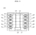
- Fig. 1 is a longitudinal sectional view of a magnetic bearing device which represents an embodiment of the present invention;
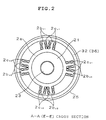
- Fig. 2 is a cross-sectional view taken along the lines A-A and E-E of Fig. 1;
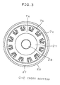
- Fig. 3 is a cross-sectional view taken along the line C-C of Fig. 1;
- Fig. 4 is a cross-sectional view taken along the lines B-B and D-D of Fig. 1; and
- Fig. 5 is a diagram showing an example of a conventional magnetic bearing device of a five axes control type.
-
- A preferred embodiment of the present invention will be described below with reference to Figs. 1 through 4, in which components identical or corresponding to those shown in Fig. 5 are indicated by the same reference symbols. The description for the corresponding components will not be repeated.
- Referring to Fig. 1, an upper radial
position detection sensor 2, an upperradial electromagnet 1, amotor 7, a lowerradial electromagnet 5 and a lower radialposition detection sensor 6 are mounted in this order on the circumferential surface of astator 21 from an uppermost position to a lowermost position thereon. Ashaft 23 is provided by being passed through a central portion of thestator 21. Astopper 24 is fixed to the lower end of theshaft 23, while anouter rotor 25 is fixed to the upper end of theshaft 23. Thestopper 24 prevents the rotating member from coming off thestator 21. - An
outer rotor 25 has a hollow cylindrical shape such as to cover the upper radialposition detection sensor 2, the upperradial electromagnet 1, themotor 7, the lowerradial electromagnet 5, and the lower radialposition detection sensor 6. - The upper radial position detection sensor 2 (having the same construction as the lower radial position detection sensor 6) is formed by winding radial position detection coils 2c around projecting portions 2b extending from an iron core 2a, as shown in Fig. 2. The projecting portions 2b and the radial position detection coils 2c are formed in four circularly-distributed places such as to form magnetic pole pairs in X- and Y-directions.
- That is, the projecting portions 2bx1 and the radial position detection coils 2cx1 are provided in the X-axis plus direction; the projecting portions 2bx2 and the radial position detection coils 2cx2, in the X-axis minus direction; the projecting portions 2by1 and the radial position detection coils 2cy1, in the Y-axis plus direction; and the projecting portions 2by2 and the radial position detection coils 2cy2, in the Y-axis minus direction.
- Also, the upper radial electromagnet 1 (having the same construction as the lower radial electromagnet 5) is formed by winding radial position adjustment coils 1c around projecting portions 1b extending from an iron core 1a, as shown in Fig. 4. The projecting portions 1b and the radial position adjustment coils 1c are formed in four circularly-distributed places such as to form magnetic pole pairs in X- and Y-directions, respectively.
- That is, the projecting portions 1bx1 and the radial position adjustment coils 1cx1 are provided in the X-axis plus direction; the projecting portions 1bx2 and the radial position adjustment coils 1cx2, in the X-axis minus direction; the projecting portions 1by1 and the radial position adjustment coils 1cy1, in the Y-axis plus direction; and the projecting portions 1by2 and the radial position adjustment coils 1cy2, in the Y-axis minus direction.
- The radial position detecting coils 2c of the upper radial
position detection sensor 2, and the radial position adjustment coils 1c of the upperradial electromagnet 1 are provided in the same directions. - The
motor 7 is formed by winding motor coils 7c around projecting portions 7b extending from aniron core 7a, as shown in Fig. 3. The core of themotor 7 is formed by theiron core portion 7a and the projecting portions 7b. The projecting portions 7b and the motor coils 7c are formed in twelve places circularly arranged at regular intervals. - On the inner surface of the
outer rotor 25, an upper radialposition detection target 32 is fixed circularly while being positioned so as to face the projecting portions 2b of the upper radialposition detection sensor 2. Similarly, a lower radialposition detection target 36, an upper radialposition adjustment target 31, and a lower radialposition adjustment target 35 are fixed on the inner surface of therotor 25 while being positioned so as to face projecting portions 6b of the lower radialposition detection sensor 6, the projecting portions 1b of the upperradial electromagnet 1, and projecting portions 5b of the lowerradial electromagnet 5, respectively. - Each of the upper radial
position detection target 32, the lower radialposition detection target 36, the upper radialposition adjustment target 31, and the lower radialposition adjustment target 35 is formed a laminated piece of steel. - A
motor magnet 37 is fixed on the inner surface of therotor 25 while being positioned so as to face the projecting portions 7b of themotor 7. Themotor magnet 37 is magnetized so as to have a predetermined number of magnetic poles. - The operation of the embodiment of the present invention will now be described.
- An X-direction displacement of an upper portion of the
outer rotor 25 is detected with the radial position detection coils 2cx1 and 2cx2, and an X-direction displacement of a lower portion of theouter rotor 25 is detected with the radial position detection coils 6cx1 and 6cx2. This detection is performed based on a change in the inductance between each sensor and theouter rotor 25. - Also, a Y-direction displacement of the upper portion of the
outer rotor 25 is detected with the radial position detection coils 2cy1 and 2cy2, and a Y-direction displacement of the lower portion of theouter rotor 25 is detected with the radial position detection coils 6cy1 and 6cy2. - The radial position adjustment coils 1cx1 and 1cx2 are excited through an adjustment meter or the like (not shown) on the basis of the detected X-direction displacements, while the radial position adjustment coils 1cy1 and 1cy2 are excited through an adjustment meter or the like (not shown) on the basis of the detected Y-direction displacements. The excited coils attract the
outer rotor 25 to adjust the radial position of the upper portion of theouter rotor 25. The radial position adjustment of the lower portion of theouter rotor 25 is also performed in the same manner. - The
motor magnet 37 and the motor coils 7c drive and rotate theouter rotor 25 by the magnetic attractions generated between them, and also support theouter rotor 25 in the predetermined position in the axial direction by their magnetic attractions. This support is also effected when theouter rotor 25 is in a stationary state. - In the above-described arrangement, there is no need for additional means for supporting the axial position of the
outer rotor 25 at the predetermined position, such as those shown in Fig. 5, i.e., theaxial sensor 13, the upper axial electromagnet 11a, the loweraxial electromagnet 11b, and the targets facing these components. - Therefore, the manufacturing cost and the size of the
magnetic bearing device 20 can be reduced by reducing the number of component parts, as described above. Further, since theaxial sensor 13, the upper axial electromagnet 11a and the loweraxial electromagnet 11b are not necessary, electric power can be correspondingly saved. - The present invention can also be applied to a magnetic bearing device using an integral bearingless motor constructed in such a manner that the motor coils 7c and radial position adjustment coils 1c or the radial position adjustment coils 5c are formed on one iron core. Also in such a case, the
axial sensor 13 and other components can be removed. - In the bearingless motor, the magnetic forces generated by the motor coils 7c are unbalanced by the magnetic forces generated by the radial position adjustment coils 1c or the radial position adjustment coils 5c to magnetically adjust the radial position while producing a rotating force.
- According to the present invention, as described above, the rotating member is supported at the desired axial position by axial direction components of magnetic attractions generated between the permanent magnet and the rotating means, thereby eliminating the need for detection of and control of the position of the rotating member in the axial direction. Consequently, the number of component parts can be reduced.
Claims (1)
- A magnetic bearing device comprising:a rotating member floated and supported by magnetic force;at least one permanent magnet arranged on the rotating member;rotating means for rotating the rotating member by magnetic fields generated through a core on which motor coils are provided, and which is spaced apart from the permanent magnet in a radial direction so as to form a predetermined gap therebetween;at least one set of radial position detection means for detecting the radial position and/or an inclination of the rotating member; andat least one set of radial position adjustment means for adjusting the radial position and/or the inclination of the rotating member based on the radial position and/or the inclination detected by the radial position detection means, whereinthe rotating member is supported at a desired axial position by axial direction components of magnetic attractions generated between the permanent magnet and the core.
Applications Claiming Priority (2)
| Application Number | Priority Date | Filing Date | Title |
|---|---|---|---|
| JP21096099 | 1999-07-26 | ||
| JP11210960A JP2001041237A (en) | 1999-07-26 | 1999-07-26 | Magnetic bearing device |
Publications (2)
| Publication Number | Publication Date |
|---|---|
| EP1072803A2 true EP1072803A2 (en) | 2001-01-31 |
| EP1072803A3 EP1072803A3 (en) | 2002-08-07 |
Family
ID=16597970
Family Applications (1)
| Application Number | Title | Priority Date | Filing Date |
|---|---|---|---|
| EP00306102A Withdrawn EP1072803A3 (en) | 1999-07-26 | 2000-07-18 | Magnetic bearing device |
Country Status (3)
| Country | Link |
|---|---|
| US (1) | US6362549B1 (en) |
| EP (1) | EP1072803A3 (en) |
| JP (1) | JP2001041237A (en) |
Cited By (2)
| Publication number | Priority date | Publication date | Assignee | Title |
|---|---|---|---|---|
| CN101769334A (en) * | 2008-12-31 | 2010-07-07 | 张玉宝 | Single degree of freedom magnetic suspension rotor support system as well as magnetic bearing and weight losing method |
| CN104728262A (en) * | 2015-01-21 | 2015-06-24 | 北京石油化工学院 | Outer-rotor radial spherical pure electromagnetic magnetic bearing |
Families Citing this family (5)
| Publication number | Priority date | Publication date | Assignee | Title |
|---|---|---|---|---|
| US8698367B2 (en) * | 2008-04-17 | 2014-04-15 | Synchrony, Inc. | High-speed permanent magnet motor and generator with low-loss metal rotor |
| JP2011520410A (en) | 2008-04-18 | 2011-07-14 | シンクロニー,インコーポレイテッド | Magnetic thrust bearings using integrated electronics. |
| US9583991B2 (en) * | 2009-06-24 | 2017-02-28 | Synchrony, Inc. | Systems, devices, and/or methods for managing magnetic bearings |
| EP2280471B1 (en) * | 2009-07-30 | 2019-08-07 | Levitronix GmbH | Electric rotary drive |
| EP2586121B1 (en) | 2010-06-23 | 2019-12-11 | Synchrony, Inc. | Split magnetic thrust bearing |
Citations (3)
| Publication number | Priority date | Publication date | Assignee | Title |
|---|---|---|---|---|
| US4779614A (en) * | 1987-04-09 | 1988-10-25 | Nimbus Medical, Inc. | Magnetically suspended rotor axial flow blood pump |
| US5285123A (en) * | 1992-04-06 | 1994-02-08 | Doryokuro Kakunenryo Kaihatsu Jigyodan | Turbo-generator |
| EP0939480A2 (en) * | 1998-02-25 | 1999-09-01 | Electric Boat Corporation | Permanent magnet synchronous machine with integrated magnetic bearings |
Family Cites Families (4)
| Publication number | Priority date | Publication date | Assignee | Title |
|---|---|---|---|---|
| JPH0646036B2 (en) * | 1982-11-19 | 1994-06-15 | セイコー電子工業株式会社 | Axial flow molecular pump |
| JP3463218B2 (en) * | 1993-12-24 | 2003-11-05 | 光洋精工株式会社 | Magnetic bearing device |
| JP3421904B2 (en) * | 1996-08-07 | 2003-06-30 | 光洋精工株式会社 | Magnetic bearing spindle device for machine tools |
| US5739609A (en) * | 1997-04-09 | 1998-04-14 | Koyo Seiko Co., Ltd. | Magnetic bearing apparatus |
-
1999
- 1999-07-26 JP JP11210960A patent/JP2001041237A/en active Pending
-
2000
- 2000-07-14 US US09/616,644 patent/US6362549B1/en not_active Expired - Fee Related
- 2000-07-18 EP EP00306102A patent/EP1072803A3/en not_active Withdrawn
Patent Citations (3)
| Publication number | Priority date | Publication date | Assignee | Title |
|---|---|---|---|---|
| US4779614A (en) * | 1987-04-09 | 1988-10-25 | Nimbus Medical, Inc. | Magnetically suspended rotor axial flow blood pump |
| US5285123A (en) * | 1992-04-06 | 1994-02-08 | Doryokuro Kakunenryo Kaihatsu Jigyodan | Turbo-generator |
| EP0939480A2 (en) * | 1998-02-25 | 1999-09-01 | Electric Boat Corporation | Permanent magnet synchronous machine with integrated magnetic bearings |
Cited By (4)
| Publication number | Priority date | Publication date | Assignee | Title |
|---|---|---|---|---|
| CN101769334A (en) * | 2008-12-31 | 2010-07-07 | 张玉宝 | Single degree of freedom magnetic suspension rotor support system as well as magnetic bearing and weight losing method |
| CN101769334B (en) * | 2008-12-31 | 2015-10-21 | 张玉宝 | A kind of single-degree-of-freedom magnetic suspension rotor support system and magnetic bearing and weight losing method |
| CN104728262A (en) * | 2015-01-21 | 2015-06-24 | 北京石油化工学院 | Outer-rotor radial spherical pure electromagnetic magnetic bearing |
| CN104728262B (en) * | 2015-01-21 | 2017-06-06 | 北京石油化工学院 | A kind of pure electromagnetism magnetic bearing of external rotor radial sphere |
Also Published As
| Publication number | Publication date |
|---|---|
| JP2001041237A (en) | 2001-02-13 |
| US6362549B1 (en) | 2002-03-26 |
| EP1072803A3 (en) | 2002-08-07 |
Similar Documents
| Publication | Publication Date | Title |
|---|---|---|
| US6727617B2 (en) | Method and apparatus for providing three axis magnetic bearing having permanent magnets mounted on radial pole stack | |
| EP2209186B1 (en) | Magnetically-levitated motor and pump | |
| KR100403857B1 (en) | Motor of magnetic lifting type | |
| EP2012019B1 (en) | Bearing apparatus and centrifugal compressor provided with same | |
| JP2008537872A (en) | Method for stabilizing a magnetically levitated object | |
| US7847453B2 (en) | Bearingless step motor | |
| JP2002354767A (en) | Magnetic levitation motor | |
| EP1655820A3 (en) | Integrated magnetic levitation and rotation system | |
| EP2422100B1 (en) | A magnetic bearing, a rotary stage, and a reflective electron beam lithography apparatus | |
| EP1857695B1 (en) | Ball bearing | |
| EP1072803A2 (en) | Magnetic bearing device | |
| JP3850195B2 (en) | Magnetic levitation motor | |
| WO2014007851A1 (en) | Active magnetic bearing assembly and arrangement of magnets therefor | |
| US20130207496A1 (en) | System and method for performing magnetic levitation in an energy storage flywheel | |
| JP4200775B2 (en) | Flywheel power storage device | |
| US20040174080A1 (en) | Magnetic bearing | |
| KR20110072896A (en) | Toroidally-wound self-bearing brushless dc motor | |
| US7719152B2 (en) | Magnetic levitation actuator | |
| JPS6399742A (en) | Magnetic bearing integrating type motor | |
| JP2004316756A (en) | Five-axis control magnetic bearing | |
| JPH10299772A (en) | Bearing device | |
| JP2020526166A (en) | Electromechanical system | |
| KR102544989B1 (en) | Eddy current levitation motor and system | |
| JP2005325988A (en) | Magnetic bearing | |
| JP2004286176A (en) | Magnetic bearing device |
Legal Events
| Date | Code | Title | Description |
|---|---|---|---|
| PUAI | Public reference made under article 153(3) epc to a published international application that has entered the european phase |
Free format text: ORIGINAL CODE: 0009012 |
|
| AK | Designated contracting states |
Kind code of ref document: A2 Designated state(s): AT BE CH CY DE DK ES FI FR GB GR IE IT LI LU MC NL PT SE |
|
| AX | Request for extension of the european patent |
Free format text: AL;LT;LV;MK;RO;SI |
|
| PUAL | Search report despatched |
Free format text: ORIGINAL CODE: 0009013 |
|
| AK | Designated contracting states |
Kind code of ref document: A3 Designated state(s): AT BE CH CY DE DK ES FI FR GB GR IE IT LI LU MC NL PT SE |
|
| AX | Request for extension of the european patent |
Free format text: AL;LT;LV;MK;RO;SI |
|
| 17P | Request for examination filed |
Effective date: 20030107 |
|
| AKX | Designation fees paid |
Designated state(s): DE FR GB |
|
| 17Q | First examination report despatched |
Effective date: 20040316 |
|
| STAA | Information on the status of an ep patent application or granted ep patent |
Free format text: STATUS: THE APPLICATION IS DEEMED TO BE WITHDRAWN |
|
| 18D | Application deemed to be withdrawn |
Effective date: 20040928 |