EP1069723A2 - Method for wireless differential communication using multiple transmitter antennas - Google Patents
Method for wireless differential communication using multiple transmitter antennas Download PDFInfo
- Publication number
- EP1069723A2 EP1069723A2 EP00305565A EP00305565A EP1069723A2 EP 1069723 A2 EP1069723 A2 EP 1069723A2 EP 00305565 A EP00305565 A EP 00305565A EP 00305565 A EP00305565 A EP 00305565A EP 1069723 A2 EP1069723 A2 EP 1069723A2
- Authority
- EP
- European Patent Office
- Prior art keywords
- matrix
- data
- matrices
- baseband signal
- transmission
- Prior art date
- Legal status (The legal status is an assumption and is not a legal conclusion. Google has not performed a legal analysis and makes no representation as to the accuracy of the status listed.)
- Granted
Links
Images


Classifications
-
- H—ELECTRICITY
- H04—ELECTRIC COMMUNICATION TECHNIQUE
- H04L—TRANSMISSION OF DIGITAL INFORMATION, e.g. TELEGRAPHIC COMMUNICATION
- H04L1/00—Arrangements for detecting or preventing errors in the information received
- H04L1/02—Arrangements for detecting or preventing errors in the information received by diversity reception
- H04L1/06—Arrangements for detecting or preventing errors in the information received by diversity reception using space diversity
- H04L1/0618—Space-time coding
- H04L1/0625—Transmitter arrangements
-
- H—ELECTRICITY
- H04—ELECTRIC COMMUNICATION TECHNIQUE
- H04L—TRANSMISSION OF DIGITAL INFORMATION, e.g. TELEGRAPHIC COMMUNICATION
- H04L1/00—Arrangements for detecting or preventing errors in the information received
- H04L1/02—Arrangements for detecting or preventing errors in the information received by diversity reception
- H04L1/06—Arrangements for detecting or preventing errors in the information received by diversity reception using space diversity
- H04L1/0612—Space-time modulation
Definitions
- the present invention relates to method for wireless communication; and more particularly, to differential wireless communication using multiple transmitter antennas.
- training intervals cut into the available time during which data may be transmitted.
- the length of this interval increases as the number of transmitter antennas is increased.
- the propagation coefficients can be treated as constant only over an average period of time referred to as the fading coherence interval.
- training should be repeated at least once per such interval.
- fading is very rapid in some environments, such as those in which a mobile station is operating within a rapidly moving vehicle.
- the time between fades may be too short for the communication system to learn the propagation coefficients belonging to even one transmitting antenna, much less those of a multiple antenna array.
- each message to be transmitted is transformed into a sequence of signals selected from a constellation of L possible signals, L a positive integer.
- each transmitted signal embodies a number of bits given by log L.
- log will denote the binary logarithm.
- Each of these symbols is, itself, a time sequence of complex amplitudes for transmission by the transmitting antenna or antennas. The transmissions by all of the antennas in the transmitting array are concerted. All of these transmissions (for a given signal) are made in the same sequence of T successive time units (which we refer to as symbol intervals), T a positive integer.
- a signal may be represented by a complex-valued matrix having T rows and M columns.
- Each column corresponds to a respective antenna of the transmitting array, and represents the sequence of complex amplitudes to be transmitted by the antenna.
- Each row corresponds to a particular one of the T symbol intervals, and describes the complex amplitude to be transmitted by each respective antenna during that interval.
- Such a set of complex amplitudes is referred to as a "symbol.”
- Each symbol is distributed in space (i.e., across the transmitting array), and each signal is composed of T symbols distributed in time.
- each signal matrix must have the property that all of its columns are orthonormal.
- P is the average power fed into each antenna.
- L signals there are L signals, and M columns per signal. Thus, over the entire constellation, there are L ⁇ M columns. Because there will typically be many signals in the constellation (constellation sizes in the hundreds of thousands, or even more, are desirable in at least some applications), L ⁇ M will typically be much greater than T. Well known mathematical properties dictate that there can be no more than T mutually orthonormal column vectors. Therefore, it will be unlikely that, given a randomly chosen pair of signal matrices, the columns of one such matrix will be orthogonal to the columns of the other.
- differential phase modulation Another technique that tends to mitigate the effects of fading is differential phase modulation, in which phase differences carry transmitted information.
- differential phase modulation is a known technique for single-antenna transmission and reception in fading environments, there are no known generalizations of this technique for use with an arbitrary number of antennas.
- the method of communication according to the present invention is a method of differential communication for a multiple transmitter array.
- a plurality of baseband signals are generated.
- Each baseband signal includes one or more sequences, in time, of complex numbers, each sequence to be transmitted from a respective antenna of the multiple transmitter antenna array.
- Each baseband signal is representable as a transmission matrix in which each column represents a respective antenna and each row represents a respective time segment.
- Each transmission matrix is generated based on input data and a previous transmission matrix representing a previously transmitted baseband signal.
- the baseband signals are modulated on a carrier to form transmit carrier-level signals, and the transmit carrier-level signals are transmitted by the multiple transmitter antenna array.
- Receive carrier-level signals are received by at least one antenna at the receiver end.
- Each of the receive carrier-level signals are formed from the transmit carrier-level signals passing through a channel.
- the receive carrier-level signals are demodulated to form a plurality of receive baseband signals.
- Each receive baseband signal includes one or more receive sequences, in time, of complex numbers.
- Each receive baseband signal is representable as a reception matrix in which each column represents a respective receiver antenna and each row represents a respective time segment.
- Each reception matrix depends on data encoded therein and a previous reception matrix representing a previously received receive baseband signal.
- the receive baseband signals are processed to obtain data represented thereby.
- Differential modulation has long been used in single-antenna unknown-channel links when the channel has a phase response that is approximately constant from one time sample to the next.
- Differential modulation encodes the transmitted information into phase differences from symbol to symbol.
- the receiver decodes the information in the current symbol by comparing its phase to the phase of the previous symbol.
- Differential modulation is widely used because many continuously fading channels change little between successive time samples. In fact, many continuously fading channels are approximately constant for a time interval often much larger than two samples.
- Differential modulation with a single antenna employs blocks of two time samples, since information is essentially transmitted by first providing a reference symbol and then a differentially phase-shifted symbol. Of course, after the starting symbol, each symbol acts as a reference for the next symbol, so signals essentially occupy two symbols but overlap by one symbol.
- the method according to the present invention applies such a scheme with M>1 transmitter antennas.
- Fig. 1 is a schematic block diagram of a communication system for transmitting and receiving signals in accordance with the invention.
- a baseband signal 10 input to a transmitting array of antennas 15.1-15.3 is transmitted to a receiving array of antennas 20.1, 20.2.
- N is the number of antennas in the receiving array, which may be 1 or greater.
- Fig. 1 is an example communication system, and that the present invention applies to a communication system with two or more transmitting antennas and any number of receiving antennas.
- t 1
- t 1
- t 1
- t 1
- Fig. 1 shows the t 'th such row being input, with each entry in the row input to a respective one of antennas 15.1-15.3.
- Each entry of the signal matrix represents a complex-valued baseband voltage level which, for transmission, is modulated onto the carrier frequency according to known methods.
- the antenna response is amplified and demodulated to baseband according to known methods.
- Receiver noise which is assumed to be statistically independent among the receivers and symbol periods, is represented in the figure as a component w t 1 added to the output of antenna 20.1 and a component w t 2 added to the output of antenna 20.2 at each time t .
- H be the matrix whose entries are h ij. .
- W represents the additive noise
- S is a matrix whose t , m entry represents a signal transmitted at time t and on transmitter m
- ⁇ is the signal-to-noise ratio.
- h ij are independent CN (0,1) random variables (where CN (0,1) is the complex-normal zero-mean unit-variance distribution), but the present invention is not restricted to this assumption.
- the signals ⁇ 1 , ..., ⁇ L are 2M ⁇ M matrices whose first halves are I M , and whose second halves are used to form the transmission matrix in our M -antenna differential modulation scheme.
- Each of the V l data matrices (and L signals) represents a different integer l .
- Fig. 2 schematically displays multiple-antenna differential modulation.
- each of the M columns of each transmission matrix S ⁇ (which are M ⁇ M matrices) represents a sequence of complex numbers transmitted on a respective one of the M antennas as functions of time for M symbols.
- the sequence or sequences of complex numbers form a baseband signal which is modulated on a carrier and transmitted by the multiple transmitter antenna array.
- the scaling factor ⁇ M normalizes the transmitted signal power, z ⁇ represents the ⁇ th integer data for transmission and ⁇ represents the order of transmission. Accordingly, the first and second data sequences z 1 and z 2 transmitted could be the same integer.
- a demodulator in a receiver receives receive carrier-level signals, each of which is formed from the transmit carrier-level signals transmitted from a multiple transmitter antenna array passing through a channel, using at least one receiver antenna.
- the demodulator demodulates the receive carrier-level signals to form a plurality of receive baseband signals, each receive baseband signal includes one or more receive sequences, in time, of complex numbers.
- Each receive sequence is a linear combination of the transmit sequences.
- Each receive baseband signal is representable as a reception matrix X ⁇ , where X ⁇ is an M ⁇ N matrix, in which each column represents a respective receiver antenna and each row represents a respective time segment.
- each reception matrix depends on data encoded therein and a previous reception matrix representing a previously received receive baseband signal.
- ⁇ m (A) is the mth singular value of matrix A.
- each reception matrix depends on a data matrix representing the data encoded therein pre-multiplied by the previous reception matrix. Equation (13) further states that each data matrix is correlated with a previous reception matrix and a current reception matrix, and that the data sequence corresponding to the data matrix having a highest correlation result is output as the data.
- the matrix of fading coefficients H does not appear in the fundamental differential receiver equation (13).
- this equation shows that the signal V z ⁇ appears to be transmitted through a channel with fading response X ⁇ - 1 , which is known to the receiver, and corrupted by noise with twice the variance. This corresponds to the well known result that standard single-antenna differential modulation suffers from approximately a 3 dB performance loss in effective SNR when the channel is unknown versus when it is known.
- Equation (13) demonstrates that our multiple-antenna differential setting appears to turn the original unknown-channel communication problem into a known channel problem. First the connection between known and unknown channels will be described.
- a larger product equates to a smaller error probability.
- Equation (24) says that minimizing the singular values of the correlations of the unknown-channel signals is equivalent to maximizing the singular values of the differences of the known-channel signals.
- a large ⁇ ll ' equates to small pairwise error probability (see equation 20a) when ⁇ is large and the channel is unknown.
- equation (19) states that large
- a constellation of good known-channel transmission matrices can be augmented with an identity matrix block to form a constellation of good unknown-channel matrix signals.
- a constellation of good unknown-channel signals of the form (4) has V l matrices that form a constellation of good known-channel signals.
- the identity block can be viewed as training from which the channel is learned before the second block carrying data is sent. Differential modulation, of course, lets the training and data blocks overlap.
- X ⁇ V z ⁇ X ⁇ -1 + ⁇ 2 W ' ⁇ .
- X ⁇ - 1 can be viewed as a known channel through which the data matrix V z ⁇ is sent. Demodulating z ⁇ using (16) results in the following: This estimate is exactly the maximum likelihood demodulator for the unknown channel (10):
- V comprises unitary matrices
- a group constellation is that the transmitter never has to explicitly multiply matrices, but only needs to compute (31) using a lookup table.
- Another advantage is simplified design. Good constellations are often found by searching over large candidate sets.
- Fig. 3 illustrates a schematic representation of M-antenna differential modulation according to the present invention when the constellation forms a group.
- the similarity transform does not effect the error performance of the constellation because it is equivalent to postmultiplying every signal ⁇ l by the unitary M ⁇ M matrix P and premultiplying ⁇ l by the unitary 2 M ⁇ 2 M matrix
- V is commutative is equivalent to assuming that all of its elements are diagonal matrices. If all the V l are diagonal, then the signals ⁇ l consist of two diagonal blocks (the first of which is identity). This implies that at any given time only one antenna is active. We call these signals diagonal .
- the value of l is determined by the data. It is important to note that the phase shifts are potentially different for each antenna.
- the search space can be reduced using the following rules:
- the performance of the constellations listed in the table of Fig. 4 was examined by sending the signals over a simulated continuously fading Rayleigh channel.
- the fading is assumed to be independent between antennas but correlated in time according to Jakes' model.
- the Jakes correlation function has its first zero at t ⁇ 153.
Abstract
Description
- The present invention relates to method for wireless communication; and more particularly, to differential wireless communication using multiple transmitter antennas.
- Fading is one of several physical phenomena that tend to increase error rates, or to reduce channel capacity, in wireless transmission systems. Fading is the result of destructive interference, at the receiver, between correlated signal portions that because of scattering have arrived over different-length paths. Multiple antenna arrays can be used in wireless communication to reduce error rates and increase transmission rates.
- In certain fading environments, the theoretical capacity of a multiple-antenna communication link increases linearly with the size of the transmitter or receiver array, this effect being determined by the array having the lesser number of antennas. This effect has been predicted for rich scattering environments in which fading is "flat." That is, the propagation coefficients that describe the effect of the physical transmission channel on the transmitted signal are approximately independent of frequency over the signal bandwidth. Flat fading can be achieved in practice for a particular environment if the bandwidth is not too great, or if it is restricted appropriately.
- Significantly, such a linear increase in capacity occurs only if the propagation coefficients between all pairs of transmitter and receiver antennas are known to the receiver. In practice, this condition can be met only if the receiver is trained, from time to time, by receiving known training signals from the transmitter.
- Communication methods that use such a training procedure are described, for example, in the co-pending U.S. Patent Application Serial No. 08/938,168, commonly assigned herewith, filed September 26, 1997 by B.M. Hochwald et al. under the title, "Multiple Antenna Communication System and Method Thereof."
- Other co-pending patent applications, commonly assigned herewith, that describe related subject matter are Serial No. 08/673,981, filed on July 1, 1996 by G.J. Foschini under the title "Wireless Communications System Having a Layered Space-Time Architecture Employing Multi-Element Antennas," Serial No. 09/060,657, filed on April 15, 1998 by G.J. Foschini and G.D. Golden under the title "Wireless Communications System Having a Space-Time Architecture Employing Multi-Element Antennas at Both the Transmitter and Receiver," and a patent application filed on July 10, 1998 by T.L. Marzetta under the title "Determining Channel Characteristics in a Space-Time Architecture Wireless Communication System Having Multi-Element Antennas."
- Unfortunately, training intervals cut into the available time during which data may be transmitted. The length of this interval increases as the number of transmitter antennas is increased. Moreover, the propagation coefficients can be treated as constant only over an average period of time referred to as the fading coherence interval. To be effective, training should be repeated at least once per such interval. However, fading is very rapid in some environments, such as those in which a mobile station is operating within a rapidly moving vehicle. For rapidly fading environments, the time between fades may be too short for the communication system to learn the propagation coefficients belonging to even one transmitting antenna, much less those of a multiple antenna array.
- Thus, there remains a need to more fully realize, in practice, the theoretical benefits of multiple antenna arrays in fading environments.
- In the co-pending U.S. Patent Application Serial No. 09/134,297, commonly assigned herewith, filed on August 14, 1998 by B.M. Hochwald et al. under the title, "Wireless Transmission Method for Antenna Arrays, Having Improved Resistance to Fading," there was described a new method of signal modulation. This new method, which we refer to as "Unitary Space-Time Modulation (USTM)," is robust against fading and receiver-induced noise in flat fading environments. Significantly, it does not require knowledge of the propagation coefficients, although in some implementations, such knowledge can be used to further improve performance.
- In USTM, each message to be transmitted is transformed into a sequence of signals selected from a constellation of L possible signals, L a positive integer. (Thus, each transmitted signal embodies a number of bits given by log L. In the present discussion, "log" will denote the binary logarithm.) Each of these symbols is, itself, a time sequence of complex amplitudes for transmission by the transmitting antenna or antennas. The transmissions by all of the antennas in the transmitting array are concerted. All of these transmissions (for a given signal) are made in the same sequence of T successive time units (which we refer to as symbol intervals), T a positive integer.
- Thus, a signal may be represented by a complex-valued matrix having T rows and M columns. Each column corresponds to a respective antenna of the transmitting array, and represents the sequence of complex amplitudes to be transmitted by the antenna. Each row corresponds to a particular one of the T symbol intervals, and describes the complex amplitude to be transmitted by each respective antenna during that interval. Such a set of complex amplitudes is referred to as a "symbol." Each symbol is distributed in space (i.e., across the transmitting array), and each signal is composed of T symbols distributed in time.
- Significantly, each signal matrix must have the property that all of its columns are orthonormal. (It should be noted in this regard that corresponding to a signal matrix Φ, the baseband signals provided to the transmitting array are represented by matrix S, where
- There are L signals, and M columns per signal. Thus, over the entire constellation, there are L×M columns. Because there will typically be many signals in the constellation (constellation sizes in the hundreds of thousands, or even more, are desirable in at least some applications), L×M will typically be much greater than T. Well known mathematical properties dictate that there can be no more than T mutually orthonormal column vectors. Therefore, it will be unlikely that, given a randomly chosen pair of signal matrices, the columns of one such matrix will be orthogonal to the columns of the other.
- If such orthogonality between the respective columns of signal pairs were possible, the probability of confusing one received signal for another would be reduced to its ideal minimum value. Given that this ideal condition is unattainable, it is desirable, instead, to design the signal constellation in such way that correlations between pairs of signal matrices, of a kind that tends to increase the error probability, are made as small as possible.
- U.S. Patent Application Serial No. 09/134,297, cited above, describes techniques for minimizing these correlations that are most useful when the number M of transmitting antennas is relatively small. Commonly assigned U.S. Patent Application Serial No. 09/206,843, filed on December 7, 1998, by B.M. Hochwald et al. under the title, "Wireless Transmission Method for Antenna Arrays Using Unitary Space-Time Signals," describes a more powerful technique that can readily generate signal constellations of low correlation when M, L, and T are relatively large, without demanding impractical amounts of computational resources.
- Another technique that tends to mitigate the effects of fading is differential phase modulation, in which phase differences carry transmitted information. Although differential phase modulation is a known technique for single-antenna transmission and reception in fading environments, there are no known generalizations of this technique for use with an arbitrary number of antennas.
- The method of communication according to the present invention is a method of differential communication for a multiple transmitter array. In the method, a plurality of baseband signals are generated. Each baseband signal includes one or more sequences, in time, of complex numbers, each sequence to be transmitted from a respective antenna of the multiple transmitter antenna array. Each baseband signal is representable as a transmission matrix in which each column represents a respective antenna and each row represents a respective time segment. Each transmission matrix is generated based on input data and a previous transmission matrix representing a previously transmitted baseband signal.
- The baseband signals are modulated on a carrier to form transmit carrier-level signals, and the transmit carrier-level signals are transmitted by the multiple transmitter antenna array.
- Receive carrier-level signals are received by at least one antenna at the receiver end. Each of the receive carrier-level signals are formed from the transmit carrier-level signals passing through a channel. The receive carrier-level signals are demodulated to form a plurality of receive baseband signals. Each receive baseband signal includes one or more receive sequences, in time, of complex numbers. Each receive baseband signal is representable as a reception matrix in which each column represents a respective receiver antenna and each row represents a respective time segment. Each reception matrix depends on data encoded therein and a previous reception matrix representing a previously received receive baseband signal. The receive baseband signals are processed to obtain data represented thereby.
- The present invention will become more fully understood from the detailed description given hereinbelow and the accompanying drawings which are given by way of illustration only, wherein like reference numerals designate corresponding parts in the various drawings, and wherein:
- Fig. 1 illustrates a schematic block diagram of a communication system for transmitting and receiving signals according to the differential communication method of the present invention;
- Fig. 2 illustrates a schematic representation of M-antenna differential modulation according to the present invention;
- Fig. 3 illustrates a schematic representation of M-antenna differential modulation according to the present invention when the constellation forms a group;
- Fig. 4 illustrates a table showing the results of searches for constellations for 2, 3, 4, and 5 transmitter antenna arrays;
- Fig. 5 illustrates the performance in terms of bit probability of error versus signal-to-noise ratio for the constellations of Fig. 4 when received by a single antenna, and wherein the data rate is 1; and
- Fig. 6 illustrates the performance in terms of bit probability of error versus signal-to-noise ratio for the constellations of Fig. 4 when received by a single antenna, and wherein the data rate is 2.
-
- Differential modulation has long been used in single-antenna unknown-channel links when the channel has a phase response that is approximately constant from one time sample to the next. Differential modulation encodes the transmitted information into phase differences from symbol to symbol. The receiver decodes the information in the current symbol by comparing its phase to the phase of the previous symbol. Differential modulation is widely used because many continuously fading channels change little between successive time samples. In fact, many continuously fading channels are approximately constant for a time interval often much larger than two samples.
- Differential modulation with a single antenna employs blocks of two time samples, since information is essentially transmitted by first providing a reference symbol and then a differentially phase-shifted symbol. Of course, after the starting symbol, each symbol acts as a reference for the next symbol, so signals essentially occupy two symbols but overlap by one symbol. The method according to the present invention applies such a scheme with M>1 transmitter antennas.
- Fig. 1 is a schematic block diagram of a communication system for transmitting and receiving signals in accordance with the invention. As shown, a baseband signal 10 input to a transmitting array of antennas 15.1-15.3 is transmitted to a receiving array of antennas 20.1, 20.2. Thus, in the communication system shown, M=3 and N=2. (N is the number of antennas in the receiving array, which may be 1 or greater.) It should be noted that although one array is identified here as transmitting and the other as receiving, the principles of the invention will apply to bidirectional as well as to a unidirectional communication system. Furthermore, it should be understood that Fig. 1 is an example communication system, and that the present invention applies to a communication system with two or more transmitting antennas and any number of receiving antennas.
- The physical transmission channel between the transmitting and receiving antennas is characterized by a set of M·N propagation coefficients hij, i=1, ..., M, j=1, ..., N, each a complex number characterizing the response at receiving antenna j due to transmissions from transmitting antenna i.
- At each value t of discrete time, t=1,..., one of the rows of signals s in the signal matrix is input to the transmitting array. Fig. 1 shows the t'th such row being input, with each entry in the row input to a respective one of antennas 15.1-15.3. Each entry of the signal matrix represents a complex-valued baseband voltage level which, for transmission, is modulated onto the carrier frequency according to known methods.
- At each receiving antenna 20.1, 20.2, the antenna response is amplified and demodulated to baseband according to known methods. Receiver noise, which is assumed to be statistically independent among the receivers and symbol periods, is represented in the figure as a component w t 1 added to the output of antenna 20.1 and a component w t 2 added to the output of antenna 20.2 at each time t. After demodulation to baseband, the output of the antenna array at time t is x tn , where n=1 for antenna 20.1 and n=2 for antenna 20.2. Let H be the matrix whose entries are hij.. If H can be treated as constant during the signal duration, then over that period, the response of the receiver array is given by
- As discussed above, in differential communication with one transmitter antenna, the data information is sent in the difference of the phases of two consecutive symbols. With multiple antennas, differential modulation is accomplished by overlapping 2M ×M matrix signals Φℓ for ℓ =0, ..., L-1, where L denotes the number of symbols needed to transmit data at a particular data rate.
- Φ0, ..., Φ L -1 must have the following structure to permit overlapping:where V ℓ1 and V ℓ2 are, for the moment, arbitrary M×M complex matrices. Furthermore, by establishing Φℓ so that

- Φℓ and Φℓϒℓ, (ℓ=0, ..., L-1) are indistinguishable for arbitrary unitary M×M matrices ϒℓ. Therefore freedom exists to "preprocess" each signal Φℓ to be sent by right-multiplying by a unitary matrix so that its first M×M matrix block equals the second matrix block of the previously (also possibly preprocessed) sent symbol, say Φℓ. After Φℓ is preprocessed, because its first block equals the second block of the signal already sent, only its (normalized) second block needs to be sent. For this overlapping to succeed, it is required that a unitary transformation exist between the first block of Φℓ and the second block of Φℓ '; i.e., for any ℓ and ℓ', the equation
- The most general and preferred set of V ℓ1 and V ℓ2 matrices that satisfy (3) is, in general, obtained by choosing V ℓ1 and V ℓ2 to be unitary. If V ℓ1 and V ℓ2 are unitary for all ℓ then (2) holds, and (3) has the unitary solutionwhere

- In equation (4), the signals Φ1, ..., Φ L , are 2M×M matrices whose first halves are IM , and whose second halves are used to form the transmission matrix in our M-antenna differential modulation scheme. A transmission data rate of R bits per channel use requires a constellation with
- Fig. 2 schematically displays multiple-antenna differential modulation. Here each of the M columns of each transmission matrix S τ (which are M×M matrices) represents a sequence of complex numbers transmitted on a respective one of the M antennas as functions of time for M symbols. The sequence or sequences of complex numbers form a baseband signal which is modulated on a carrier and transmitted by the multiple transmitter antenna array.
- The first transmission is a scaled version of Φ z1 ; that is, an identity matrix
- Next, we wish to send Φ z21 . To make the identity block of Φ z2 overlap with the last sent block Vz1 , we postmultiply Φ z2 by Φ z1 . The second block of Φ z2 then becomes Vz2Vz1 and, hence,
- Accordingly, when a data integer l is to be sent, the corresponding data matrix V ℓ is selected, and transmission matrix S τ is generated using equation (5).
- Next, reception of the above transmitted signals will be described. A demodulator in a receiver receives receive carrier-level signals, each of which is formed from the transmit carrier-level signals transmitted from a multiple transmitter antenna array passing through a channel, using at least one receiver antenna. The demodulator demodulates the receive carrier-level signals to form a plurality of receive baseband signals, each receive baseband signal includes one or more receive sequences, in time, of complex numbers. Each receive sequence is a linear combination of the transmit sequences. Each receive baseband signal is representable as a reception matrix X τ, where X τ is an M×N matrix, in which each column represents a respective receiver antenna and each row represents a respective time segment. As discussed in detail below, each reception matrix depends on data encoded therein and a previous reception matrix representing a previously received receive baseband signal.
- With N receiver antennas, the stream of reception matrices is:Demodulation requires looking at two successive matrices to form a matrix with 2M rows.
 Assume that the fading coefficients are constant across the 2M time samples represented in the rows of X. Then the relationship with the sent stream is
 where ∥A∥2 is the Frobenius norm of matrix A given by the equation
- Substituting the fundamental differential transmitter equation
- As demonstrated by equation (13), each reception matrix depends on a data matrix representing the data encoded therein pre-multiplied by the previous reception matrix. Equation (13) further states that each data matrix is correlated with a previous reception matrix and a current reception matrix, and that the data sequence corresponding to the data matrix having a highest correlation result is output as the data.
- Remarkably, the matrix of fading coefficients H does not appear in the fundamental differential receiver equation (13). In fact, formally, this equation shows that the signal Vz τ appears to be transmitted through a channel with fading response X τ-1 , which is known to the receiver, and corrupted by noise with twice the variance. This corresponds to the well known result that standard single-antenna differential modulation suffers from approximately a 3 dB performance loss in effective SNR when the channel is unknown versus when it is known.
- Next, the generation of constellations for differential communication according to the present invention will be described. Equation (13) demonstrates that our multiple-antenna differential setting appears to turn the original unknown-channel communication problem into a known channel problem. First the connection between known and unknown channels will be described.
- Consider signals that are M×M matrices. The action of the channel isand has pairwise probability of error Chernoff upper bound given by

Hence, good constellations Ψ1, ..., Ψ L have singular values - The Chernoff upper bound on mistaking signals Sl and Sl' when the channel is unknown iswhere dℓℓ'l to dℓℓ'M are singular values of the M×M matrices obeying
 where Ψℓ are unitary matrices taken from a constellation of known-channel signals. Then,
Equation (24) says that minimizing the singular values of the correlations of the unknown-channel signals is equivalent to maximizing the singular values of the differences of the known-channel signals. We now define a quantity ζℓℓ' which can be compared for different constellations. - As discussed above, the fundamental differential receiver equation (13) isThis estimate is exactly the maximum likelihood demodulator for the unknown channel (10):


- These connections imply that the differential scheme can use existing constellations and demodulation methods from the known channel.
- Next, structuring the set of L data matrices as a group or part of a group will be described. Let the set of data matrices V be the set of L distinct unitary matrices V={V 0, ..., V L-1} that forms a group. This assumption simplifies the transmission scheme and the constellation design.
- An internal composition rule is imposed on V. For any ℓ,ℓ'∈ {0,...,L - 1}, it is required that
By choosing the unitary matrix to have the block formit can be assumed, without loss of generality, that
Inverse element: Because V comprises unitary matrices, the matrix products V 1 V 0, V 1 V 1,...,V 1 V L-1 are all distinct. Since these products are all in V, they must simply be a permutation of the elements of V. In particular, there exists a solution to - Of the four requirements that a group must satisfy, only the requirement of internal composition resulted in a loss of generality. The remaining requirements are naturally satisfied. Consequently, to simplify generating a set of data matrices (i.e., a constellation) it is assumed that the set of data matrices are unitary matrices and form a group or part of a group.
- Differential modulation can now be written more succinctly by letting
- One advantage of a group constellation is that the transmitter never has to explicitly multiply matrices, but only needs to compute (31) using a lookup table. Another advantage is simplified design. Good constellations are often found by searching over large candidate sets. Computing ζ (see equation (25)) for a candidate constellation requires checking (L -1)L/2 correlations of the form
- The design of constellations can be further simplified by imposing the requirement that the product of any two data matrices of V commutes; namely, that the group V is commutative. Imposing commutativity has some appealing consequences. Since V 0,...,VL -1 are unitary, they are normal matrices, and can be written asThus, assuming V is commutative is equivalent to assuming that all of its elements are diagonal matrices. If all the V ℓ are diagonal, then the signals Φℓ consist of two diagonal blocks (the first of which is identity). This implies that at any given time only one antenna is active. We call these signals diagonal.

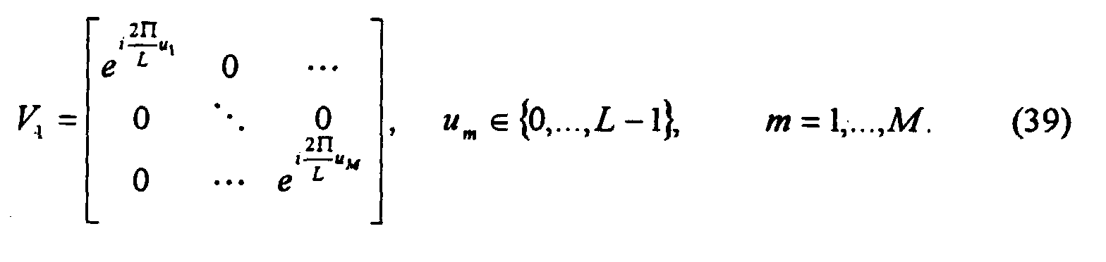
- A simple way to build the commutative group V with L elements is to make it cyclic. Then V ℓ is of the formWith this cyclic construction, the 2M×M signals Φℓ conform to a systematic design and are given by
 The ℓth signal in the constellation therefore has the form
 These signals have a very simple interpretation. At any time, only one transmitter antenna is active and transmitting either a reference symbol (which in differential modulation is actually the previously sent symbol) or a phase shifted symbol. Thus, within the τth block, antenna m transmits at time
- Signal matrices V ℓ with low pairwise probability of demodulation error form correlations (34) with singular values that are small for all ℓ' ≠ ℓ. The singular values of

- In general, if L is not prime, a finite commutative group of size L may be written as a cross product of cyclic groups. A corresponding signal construction that is multi-index and systematic may be defined. For example, choose a factorization of L as
- A special case of the multi-cyclic construction happens when
- Next, the performance of constellations of diagonal signals designed for M=1, ..., 5 transmitter antennas will be described. In the search for good constellations, some simplifying rules were employed that caused no loss of generality, regardless of the performance criterion used:
- 1) Because every antenna is statistically equivalent to every other, the ordering u 1 ≤ u 2 ≤ ... ≤ uM may be imposed.
- 2) um > 0 may be assumed, because if um = 0, then the mth antenna can only transmit the symbol 1 and is effectively rendered inoperative.
- 3) The constellation generated by u 1, ..., uM and αu 1,...,...,αuM are identical for all α relatively prime to L. From equation (40), it is seen that multiplication by α simply reorders the signals in increasing αℓ (mod L) instead of increasing ℓ.
-
- Constellations of differential unitary space-time signals can be designed with a maximin procedure: find the u 1,...,uM ∈ {0,...,L -1} that maximizeExplicit solutions to this procedure are not known, and an exhaustive computer search was conducted considering only single-index cyclic constructions K = 1. Candidates for the best set of u 1,...,uM ∈ {0,...,L -1} are generated exhaustively, tested for performance by computing ζ, and kept if they exceed the previously best candidate.

- The search space can be reduced using the following rules:
- a) Equation (52) does not change if um is replaced by L-um , and the search, therefore, may be restricted to um ∈ {0,..., L/2} (assuming L is even).
- b) If um shares a factor with L then there is an ℓ ∈ {1,...,L -1} for which um ℓ = 0 (mod L); this implies that ζ=0. Thus, the search can be restricted to um that are relatively prime to L.
- c) By Rule b), it can be assumed that u 1 is relatively prime to L. But
then there exists an α such that
- d) In equation (52), the product for ℓ and L -ℓ is the same; it is 1 for
-
- The table in Fig. 4 shows the results of our searches for constellations of
- Constellations with more than 2 RM signals, from which we would employ a subset, were not searched; however, better performing constellations could sometimes be generated in this way.
- The performance of the constellations listed in the table of Fig. 4 was examined by sending the signals over a simulated continuously fading Rayleigh channel. The fading is assumed to be independent between antennas but correlated in time according to Jakes' model. A typical physical scenario where such a model is appropriate is a base station antenna array communicating with a mobile. If we assume that the mobile is traveling at approximately 25 m/s (55 mph) and operating at 900 MHz, the Doppler shift is approximately fD = 75 Hz. The Jakes correlation between two fading coefficients t time samples apart is J 0(2πfDTst), where Ts is the sampling period and J 0 is the zero order Bessel function of the first kind. It was also assumed that Ts = 1/30,000 so TsfD = 0.0025. The Jakes correlation function has its first zero at t ≈ 153.
- Supposing that binary data are to be transmitted, bits have to be assigned to the constellation signals. It was observed that if,
- Figs. 5 and 6 show the bit error performance of M=2,3,4, and 5 transmitter antennas and one receiver antenna for R=1 and R=2, respectively. It is seen that the differential unitary space-time signals are especially effective at high SNR.
- An advantage of our diagonal signals is their simplicity. Because only one antenna transmits at any given time, one power amplifier can be switched among the antennas. But this amplifier must deliver M-times the power it would otherwise deliver if there were an array of M amplifiers simultaneously driving the other antennas. Consequently, this amplifier needs to have a larger linear operating range than an amplifier array would. Amplifiers with a large linear range are often expensive to design and build. It may therefore occasionally be desirable to have all M antennas transmitting simultaneously at lower power. In this case, the constellation is modified by post-multiplying the transmission matrices by M×M unitary matrices such as discrete Fourier transform matrices. This has the effect of smearing the transmitted symbol on any active antenna across all of the antennas. On the other hand, the entire constellation may be premultiplied by a common unitary matrix, smearing the symbols in time. Neither constellation modification affects its error performance in any way.
- The invention being thus described, it will be obvious that the same may be varied in many ways. Such variations are not to be regarded as a departure from the spirit and scope of the invention, and all such modifications are intended to be included within the scope of the following claims.
Claims (27)
- A method of wireless differential communication for a multiple transmitter antenna array, comprising:generating a plurality of baseband signals, each baseband signal including one or more sequences, in time, of complex numbers, each sequence to be transmitted from a respective antenna of said multiple transmitter antenna array, each baseband signal being representable as a transmission matrix in which each column corresponds to one of said sequences and represents a respective antenna and in which each row represents a respective time segment, each transmission matrix generated based on a previous transmission matrix representing a previously transmitted baseband signal and input data;modulating said baseband signals on a carrier to form carrier-level signals; andtransmitting said carrier-level signals from said multiple transmitter antenna array.
- The method of claim 1, wherein each transmission matrix is proportional to a matrix having orthonormal columns.
- The method of claim 1, further comprising:providing a set of data matrices, each data matrix corresponding to a different data sequence of a predetermined length such that said set of data matrices representing data sequences of said predetermined length; and whereinsaid generating step generates each transmission matrix from a selected one of said data matrices and said previous transmission matrix.
- The method of claim 3, wherein said generating step comprises:receiving said input data of said predetermined length;selecting a data matrix corresponding to said received input data; andpre-multiplying said previous transmission matrix by said selected data matrix to obtain a new transmission matrix.
- The method of claim 4, wherein each data matrix is proportional to a matrix having orthonormal columns.
- The method of claim 5, wherein said set of data matrices forms at least part of a group such that multiplying any two data matrices from said set of data matrices results in a matrix from said group.
- The method of claim 6, wherein said set of data matrices are derived from a generator matrix.
- The method of claim 7, wherein each of said data matrices is a power of said generator matrix.
- The method of claim 8, wherein said generator matrix is a diagonal matrix.
- The method of claim 5, wherein said set of data matrices is a set from a plurality of sets providing a highest transmission quality out of said plurality of sets.
- A method of wireless differential communication, comprising:receiving receive carrier-level signals, each of which is formed from said transmit carrier-level signals transmitted from a multiple transmitter antenna array passing through a channel, using at least one receiver antenna;demodulating said receive carrier-level signal sequence to form a plurality of receive baseband signals, each receive baseband signal including one or more receive sequences, in time, of complex numbers, each receive baseband signal being representable as a reception matrix in which each column corresponds to one of said receive sequences and represents a respective receiver antenna and in which each row represents a respective time segment, each reception matrix depending on data encoded therein and a previous reception matrix representing a previously received receive baseband signal; andprocessing said receive baseband signals to obtain data represented thereby.
- The method of claim 11, wherein said transmit carrier-level signals were formed from a plurality of transmit baseband signals, each transmit baseband signal including one or more transmit sequences, in time, of complex numbers, each transmit sequence having been transmitted from a respective antenna of said multiple transmitter antenna array, each transmit baseband signal being representable as a transmission matrix in which each column corresponds to one of said transmit sequences and represents a respective transmitter antenna and in which each row represents a respective time segment, each transmission matrix generated based on a transmission matrix representing a previously transmitted transmit baseband signal and input data.
- The method of claim 12, wherein each receive sequence is a linear combination of said transmit sequences.
- The method of claim 12, wherein each transmission matrix is proportional to a matrix having orthonormal columns.
- The method of claim 12, wherein each transmission matrix is generated from a data matrix selected from a set of data matrices and said transmission matrix representing a previously transmitted baseband signal, each data matrix corresponding to a different data sequence of a predetermined length such that said set of data matrices represent all possible data sequences of said predetermined length.
- The method of claim 15, wherein each transmission matrix is generated by pre-multiplying said transmission matrix representing a previously transmitted baseband signal by said selected data matrix to obtain a new transmission matrix, said selected data matrix corresponding to data of said predetermined length for transmission.
- The method of claim 11, wherein each reception matrix depends on one of a set of data matrices representing said data encoded therein pre-multiplied by said previous reception matrix, each data matrix in said set of data matrices corresponding to a different data sequence of a predetermined length such that said set of data matrices representing data sequences of said predetermined length.
- The method of claim 17, wherein each data matrix is proportional to a matrix having orthonormal columns.
- The method of claim 18, wherein said set of data matrices forms at least part of a group such that multiplying any two data matrices from said number of data matrices results in another data matrix in said set of data matrices.
- The method of claim 19, wherein said set of data matrices are derived from a generator matrix.
- The method claim 20, wherein each of said data matrices is a power of said generator matrix.
- The method of claim 21, wherein said generator matrix is a diagonal matrix.
- The method of claim 17, wherein said set of data matrices is a set from a plurality of sets providing a highest transmission quality out of said plurality of sets.
- The method of claim 17, wherein said processing step correlates each data matrix with said previous reception matrix and said reception matrix representing a current receive baseband signal, and outputs said data sequence corresponding to said data matrix having a highest correlation with said reception matrix.
- The method of claim 24, whereinsaid processing step calculates a correlation result according to the following equation,said processing step outputs said data sequence corresponding to said data matrix having a highest correlation result.
- The method of claim 17, wherein said receive baseband signals are related to each other as follows,
- A method of wireless differential communication, comprising:receiving receive carrier-level signals, each of which is formed from transmit carrier-level signals transmitted from a multiple transmitter antenna array passing through a channel, using at least one receiver antenna, said transmit carrier-level signals were formed from a plurality of transmit baseband signals, each transmit baseband signal including one or more transmit sequences, in time, of complex numbers, each transmit sequence having been transmitted from a respective antenna of said multiple transmitter antenna array, each transmit baseband signal being representable as a transmission matrix in which each column represents a respective transmitter antenna and each row represents a respective time segment, each transmission matrix generated based on a transmission matrix representing a previously transmitted transmit baseband signal and input data;demodulating said receive carrier-level signals to form a plurality of receive baseband signals; andprocessing said receive baseband signals to obtain data represented thereby.
Applications Claiming Priority (2)
| Application Number | Priority Date | Filing Date | Title |
|---|---|---|---|
| US09/356,387 US6724842B1 (en) | 1999-07-16 | 1999-07-16 | Method for wireless differential communication using multiple transmitter antennas |
| US356387 | 2003-01-31 |
Publications (3)
| Publication Number | Publication Date |
|---|---|
| EP1069723A2 true EP1069723A2 (en) | 2001-01-17 |
| EP1069723A3 EP1069723A3 (en) | 2005-08-03 |
| EP1069723B1 EP1069723B1 (en) | 2011-08-31 |
Family
ID=23401252
Family Applications (1)
| Application Number | Title | Priority Date | Filing Date |
|---|---|---|---|
| EP00305565A Expired - Lifetime EP1069723B1 (en) | 1999-07-16 | 2000-07-03 | Methods for wireless differential communication using multiple transmitter antennas |
Country Status (3)
| Country | Link |
|---|---|
| US (1) | US6724842B1 (en) |
| EP (1) | EP1069723B1 (en) |
| JP (1) | JP4657423B2 (en) |
Families Citing this family (17)
| Publication number | Priority date | Publication date | Assignee | Title |
|---|---|---|---|---|
| US7170954B2 (en) * | 1999-07-16 | 2007-01-30 | Lucent Technologies Inc. | Cayley-encodation of unitary matrices for differential communication |
| US6801579B1 (en) * | 2000-03-09 | 2004-10-05 | Lucent Technologies Inc. | Method and wireless communication using unitary space-time signal constellations |
| US6922447B1 (en) * | 2000-05-17 | 2005-07-26 | Nokia Corporation | Apparatus, and associated method, for forming a signal exhibiting space-time redundancy |
| EP1378088B1 (en) * | 2000-12-20 | 2007-07-04 | Nortel Networks Limited | Differential space-time block coding |
| US8290098B2 (en) * | 2001-03-30 | 2012-10-16 | Texas Instruments Incorporated | Closed loop multiple transmit, multiple receive antenna wireless communication system |
| KR100631177B1 (en) * | 2002-01-04 | 2006-10-04 | 노키아 코포레이션 | High rate transmission diversity transmission and reception |
| US7024166B2 (en) * | 2002-12-18 | 2006-04-04 | Qualcomm, Incorporated | Transmission diversity systems |
| EP1593225B1 (en) * | 2003-02-13 | 2007-04-25 | NTT DoCoMo, Inc. | Differential multiple-length transmit and reception diversity |
| KR100981580B1 (en) * | 2003-12-23 | 2010-09-10 | 삼성전자주식회사 | Differential Space-Time Block Codes Transceiver Apparatus For Up To 8 Transmit Antennas |
| US7570619B2 (en) * | 2004-02-13 | 2009-08-04 | Broadcom Corporation | Long training sequence method and device for wireless communications |
| KR100913873B1 (en) * | 2004-09-13 | 2009-08-26 | 삼성전자주식회사 | Apparatus and method for higher rate differential space-time block codes |
| KR100849328B1 (en) * | 2005-11-22 | 2008-07-29 | 삼성전자주식회사 | Apparatus and method for determining transmit/receive antenna in a communication system using multi antenna |
| WO2007108624A2 (en) * | 2006-03-17 | 2007-09-27 | Lg Electronics Inc. | Method for transforming data, and method for transmitting and receiving data using the same |
| US8184732B2 (en) * | 2007-05-01 | 2012-05-22 | Broadcom Corporation | Method and system for codebook design for pre-coding techniques |
| WO2008156700A2 (en) * | 2007-06-15 | 2008-12-24 | Worcester Polytechnic Institute | Precision location methods and systems |
| KR101525968B1 (en) | 2007-12-19 | 2015-06-10 | 팔콘 나노, 인코포레이티드. | Common wave and sideband mitigation communication systems and methods for increasing communication speeds, spectral efficiency and enabling other benefits |
| KR101659719B1 (en) * | 2008-07-08 | 2016-09-26 | 코닌클리케 필립스 엔.브이. | Methods and apparatus for determining relative positions of led lighting units |
Citations (1)
| Publication number | Priority date | Publication date | Assignee | Title |
|---|---|---|---|---|
| US5832044A (en) * | 1996-09-27 | 1998-11-03 | Elvino S. Sousa | Transmitter antenna diversity and fading-resistant modulation for wireless communication systems |
Family Cites Families (5)
| Publication number | Priority date | Publication date | Assignee | Title |
|---|---|---|---|---|
| US5109392A (en) * | 1989-05-11 | 1992-04-28 | Bell Telephone Laboratories, Inc. | Diversity receiver arrangement for digital signals |
| US5289499A (en) * | 1992-12-29 | 1994-02-22 | At&T Bell Laboratories | Diversity for direct-sequence spread spectrum systems |
| US6097771A (en) * | 1996-07-01 | 2000-08-01 | Lucent Technologies Inc. | Wireless communications system having a layered space-time architecture employing multi-element antennas |
| US6058105A (en) * | 1997-09-26 | 2000-05-02 | Lucent Technologies Inc. | Multiple antenna communication system and method thereof |
| US6363121B1 (en) * | 1998-12-07 | 2002-03-26 | Lucent Technologies Inc. | Wireless transmission method for antenna arrays using unitary space-time signals |
-
1999
- 1999-07-16 US US09/356,387 patent/US6724842B1/en not_active Expired - Lifetime
-
2000
- 2000-07-03 EP EP00305565A patent/EP1069723B1/en not_active Expired - Lifetime
- 2000-07-14 JP JP2000214304A patent/JP4657423B2/en not_active Expired - Fee Related
Patent Citations (1)
| Publication number | Priority date | Publication date | Assignee | Title |
|---|---|---|---|---|
| US5832044A (en) * | 1996-09-27 | 1998-11-03 | Elvino S. Sousa | Transmitter antenna diversity and fading-resistant modulation for wireless communication systems |
Non-Patent Citations (2)
| Title |
|---|
| HOCHWALD B M ET AL: "SPACE-TIME MODULATION SCHEME FOR UNKNOWN RAYLEIGH FADING ENVIRONMENTS" PROCEEDINGS OF THE ANNUAL ALLERTON CONFERENCE ON COMMUNICATION, CONTROL AND COMPUTING, 1998, pages 431-440, XP000914264 * |
| HUGHES B L: "Differential space-time modulation" WIRELESS COMMUNICATIONS AND NETWORKING CONFERENCE, 1999. WCNC. 1999 IEEE NEW ORLEANS, LA, USA 21-24 SEPT. 1999, PISCATAWAY, NJ, USA,IEEE, US, 21 September 1999 (1999-09-21), pages 145-149, XP010353768 ISBN: 0-7803-5668-3 * |
Also Published As
| Publication number | Publication date |
|---|---|
| JP2001094489A (en) | 2001-04-06 |
| EP1069723A3 (en) | 2005-08-03 |
| EP1069723B1 (en) | 2011-08-31 |
| US6724842B1 (en) | 2004-04-20 |
| JP4657423B2 (en) | 2011-03-23 |
Similar Documents
| Publication | Publication Date | Title |
|---|---|---|
| Hochwald et al. | Differential unitary space-time modulation | |
| US6363121B1 (en) | Wireless transmission method for antenna arrays using unitary space-time signals | |
| US11469929B2 (en) | Communication apparatus and communication method | |
| US6724842B1 (en) | Method for wireless differential communication using multiple transmitter antennas | |
| US7773685B2 (en) | Transmitting and receiving methods | |
| EP1538772A1 (en) | Apparatus and method for transmitting data using eigenvector selection in MIMO mobile communication systems | |
| US7430244B2 (en) | Constellation-rotating orthogonal space-time block coding technique | |
| EP0981209A2 (en) | Wireless transmission method for antenna arrays, having improved resistance to fading | |
| Xiao et al. | Space-time block coded differential spatial modulation | |
| US11233545B2 (en) | Method for wireless data communication and a communication apparatus | |
| CN101053174B (en) | Method and device for data processing in wireless communication system | |
| KR101124338B1 (en) | Mimo-based data transmission method | |
| US20070206697A1 (en) | Signal receiving method and signal receiving equipment for multiple input multiple output wireless communication system | |
| US7170954B2 (en) | Cayley-encodation of unitary matrices for differential communication | |
| EP1367760B1 (en) | Transmit/receive diversity wireless communication | |
| Varshney et al. | Space-time codes in wireless communications | |
| Dawi et al. | Performance of DSTM MIMO systems using a double extension of the Weyl group in time-varying Rayleigh channel | |
| Ji et al. | A new differential space-time modulation scheme based on weyl group | |
| Dawi et al. | Performance of DSTM MIMO Systems with 2, 4 and 8 Transmit Antennas Using Extensions of the Weyl Group | |
| Arteaga et al. | Index Coding and Signal Detection in Precoded MIMO-OFDM Systems | |
| Zhan et al. | Blockwise space-frequency code design for noncoherent MIMO OFDM systems | |
| CN102281127A (en) | Signal transmission method, system thereof, transmitter and receiver | |
| Tezcan et al. | Dual codebook antenna method for spatial multiplexing MIMO systems |
Legal Events
| Date | Code | Title | Description |
|---|---|---|---|
| PUAI | Public reference made under article 153(3) epc to a published international application that has entered the european phase |
Free format text: ORIGINAL CODE: 0009012 |
|
| AK | Designated contracting states |
Kind code of ref document: A2 Designated state(s): AT BE CH CY DE DK ES FI FR GB GR IE IT LI LU MC NL PT SE |
|
| AX | Request for extension of the european patent |
Free format text: AL;LT;LV;MK;RO;SI |
|
| PUAL | Search report despatched |
Free format text: ORIGINAL CODE: 0009013 |
|
| AK | Designated contracting states |
Kind code of ref document: A3 Designated state(s): AT BE CH CY DE DK ES FI FR GB GR IE IT LI LU MC NL PT SE |
|
| AX | Request for extension of the european patent |
Extension state: AL LT LV MK RO SI |
|
| 17P | Request for examination filed |
Effective date: 20051222 |
|
| AKX | Designation fees paid |
Designated state(s): DE FR GB |
|
| 17Q | First examination report despatched |
Effective date: 20061106 |
|
| RAP3 | Party data changed (applicant data changed or rights of an application transferred) |
Owner name: LUCENT TECHNOLOGIES INC. |
|
| GRAP | Despatch of communication of intention to grant a patent |
Free format text: ORIGINAL CODE: EPIDOSNIGR1 |
|
| RTI1 | Title (correction) |
Free format text: METHODS FOR WIRELESS DIFFERENTIAL COMMUNICATION USING MULTIPLE TRANSMITTER ANTENNAS |
|
| GRAJ | Information related to disapproval of communication of intention to grant by the applicant or resumption of examination proceedings by the epo deleted |
Free format text: ORIGINAL CODE: EPIDOSDIGR1 |
|
| GRAP | Despatch of communication of intention to grant a patent |
Free format text: ORIGINAL CODE: EPIDOSNIGR1 |
|
| RAP1 | Party data changed (applicant data changed or rights of an application transferred) |
Owner name: ALCATEL-LUCENT USA INC. |
|
| GRAS | Grant fee paid |
Free format text: ORIGINAL CODE: EPIDOSNIGR3 |
|
| GRAA | (expected) grant |
Free format text: ORIGINAL CODE: 0009210 |
|
| AK | Designated contracting states |
Kind code of ref document: B1 Designated state(s): DE FR GB |
|
| REG | Reference to a national code |
Ref country code: GB Ref legal event code: FG4D |
|
| REG | Reference to a national code |
Ref country code: DE Ref legal event code: R096 Ref document number: 60046398 Country of ref document: DE Effective date: 20111103 |
|
| PLBE | No opposition filed within time limit |
Free format text: ORIGINAL CODE: 0009261 |
|
| STAA | Information on the status of an ep patent application or granted ep patent |
Free format text: STATUS: NO OPPOSITION FILED WITHIN TIME LIMIT |
|
| 26N | No opposition filed |
Effective date: 20120601 |
|
| REG | Reference to a national code |
Ref country code: DE Ref legal event code: R097 Ref document number: 60046398 Country of ref document: DE Effective date: 20120601 |
|
| REG | Reference to a national code |
Ref country code: GB Ref legal event code: 732E Free format text: REGISTERED BETWEEN 20131024 AND 20131030 |
|
| REG | Reference to a national code |
Ref country code: FR Ref legal event code: GC Effective date: 20140715 |
|
| REG | Reference to a national code |
Ref country code: FR Ref legal event code: RG Effective date: 20141015 |
|
| REG | Reference to a national code |
Ref country code: FR Ref legal event code: PLFP Year of fee payment: 16 |
|
| REG | Reference to a national code |
Ref country code: FR Ref legal event code: PLFP Year of fee payment: 17 |
|
| PGFP | Annual fee paid to national office [announced via postgrant information from national office to epo] |
Ref country code: DE Payment date: 20160722 Year of fee payment: 17 Ref country code: GB Payment date: 20160721 Year of fee payment: 17 |
|
| PGFP | Annual fee paid to national office [announced via postgrant information from national office to epo] |
Ref country code: FR Payment date: 20160721 Year of fee payment: 17 |
|
| REG | Reference to a national code |
Ref country code: DE Ref legal event code: R119 Ref document number: 60046398 Country of ref document: DE |
|
| GBPC | Gb: european patent ceased through non-payment of renewal fee |
Effective date: 20170703 |
|
| REG | Reference to a national code |
Ref country code: FR Ref legal event code: ST Effective date: 20180330 |
|
| PG25 | Lapsed in a contracting state [announced via postgrant information from national office to epo] |
Ref country code: GB Free format text: LAPSE BECAUSE OF NON-PAYMENT OF DUE FEES Effective date: 20170703 Ref country code: DE Free format text: LAPSE BECAUSE OF NON-PAYMENT OF DUE FEES Effective date: 20180201 |
|
| PG25 | Lapsed in a contracting state [announced via postgrant information from national office to epo] |
Ref country code: FR Free format text: LAPSE BECAUSE OF NON-PAYMENT OF DUE FEES Effective date: 20170731 |
|
| REG | Reference to a national code |
Ref country code: DE Ref legal event code: R082 Ref document number: 60046398 Country of ref document: DE Representative=s name: BARKHOFF REIMANN VOSSIUS, DE Ref country code: DE Ref legal event code: R081 Ref document number: 60046398 Country of ref document: DE Owner name: WSOU INVESTMENTS, LLC, LOS ANGELES, US Free format text: FORMER OWNER: ALCATEL-LUCENT USA INC., MURRAY HILL, N.J., US |