EP1069484A2 - Developer amount indicating method, electrophotographic image forming apparatus and process cartridge - Google Patents
Developer amount indicating method, electrophotographic image forming apparatus and process cartridge Download PDFInfo
- Publication number
- EP1069484A2 EP1069484A2 EP00305884A EP00305884A EP1069484A2 EP 1069484 A2 EP1069484 A2 EP 1069484A2 EP 00305884 A EP00305884 A EP 00305884A EP 00305884 A EP00305884 A EP 00305884A EP 1069484 A2 EP1069484 A2 EP 1069484A2
- Authority
- EP
- European Patent Office
- Prior art keywords
- developer
- forming apparatus
- image forming
- indicating
- amount
- Prior art date
- Legal status (The legal status is an assumption and is not a legal conclusion. Google has not performed a legal analysis and makes no representation as to the accuracy of the status listed.)
- Granted
Links
Images


Classifications
-
- G—PHYSICS
- G03—PHOTOGRAPHY; CINEMATOGRAPHY; ANALOGOUS TECHNIQUES USING WAVES OTHER THAN OPTICAL WAVES; ELECTROGRAPHY; HOLOGRAPHY
- G03G—ELECTROGRAPHY; ELECTROPHOTOGRAPHY; MAGNETOGRAPHY
- G03G15/00—Apparatus for electrographic processes using a charge pattern
- G03G15/06—Apparatus for electrographic processes using a charge pattern for developing
- G03G15/08—Apparatus for electrographic processes using a charge pattern for developing using a solid developer, e.g. powder developer
-
- G—PHYSICS
- G03—PHOTOGRAPHY; CINEMATOGRAPHY; ANALOGOUS TECHNIQUES USING WAVES OTHER THAN OPTICAL WAVES; ELECTROGRAPHY; HOLOGRAPHY
- G03G—ELECTROGRAPHY; ELECTROPHOTOGRAPHY; MAGNETOGRAPHY
- G03G21/00—Arrangements not provided for by groups G03G13/00 - G03G19/00, e.g. cleaning, elimination of residual charge
- G03G21/16—Mechanical means for facilitating the maintenance of the apparatus, e.g. modular arrangements
- G03G21/18—Mechanical means for facilitating the maintenance of the apparatus, e.g. modular arrangements using a processing cartridge, whereby the process cartridge comprises at least two image processing means in a single unit
- G03G21/1875—Mechanical means for facilitating the maintenance of the apparatus, e.g. modular arrangements using a processing cartridge, whereby the process cartridge comprises at least two image processing means in a single unit provided with identifying means or means for storing process- or use parameters, e.g. lifetime of the cartridge
- G03G21/1878—Electronically readable memory
- G03G21/1889—Electronically readable memory for auto-setting of process parameters, lifetime, usage
-
- G—PHYSICS
- G03—PHOTOGRAPHY; CINEMATOGRAPHY; ANALOGOUS TECHNIQUES USING WAVES OTHER THAN OPTICAL WAVES; ELECTROGRAPHY; HOLOGRAPHY
- G03G—ELECTROGRAPHY; ELECTROPHOTOGRAPHY; MAGNETOGRAPHY
- G03G15/00—Apparatus for electrographic processes using a charge pattern
- G03G15/06—Apparatus for electrographic processes using a charge pattern for developing
- G03G15/08—Apparatus for electrographic processes using a charge pattern for developing using a solid developer, e.g. powder developer
- G03G15/0822—Arrangements for preparing, mixing, supplying or dispensing developer
- G03G15/0848—Arrangements for testing or measuring developer properties or quality, e.g. charge, size, flowability
- G03G15/0856—Detection or control means for the developer level
- G03G15/0858—Detection or control means for the developer level the level being measured by mechanical means
-
- G—PHYSICS
- G03—PHOTOGRAPHY; CINEMATOGRAPHY; ANALOGOUS TECHNIQUES USING WAVES OTHER THAN OPTICAL WAVES; ELECTROGRAPHY; HOLOGRAPHY
- G03G—ELECTROGRAPHY; ELECTROPHOTOGRAPHY; MAGNETOGRAPHY
- G03G21/00—Arrangements not provided for by groups G03G13/00 - G03G19/00, e.g. cleaning, elimination of residual charge
- G03G21/16—Mechanical means for facilitating the maintenance of the apparatus, e.g. modular arrangements
- G03G21/18—Mechanical means for facilitating the maintenance of the apparatus, e.g. modular arrangements using a processing cartridge, whereby the process cartridge comprises at least two image processing means in a single unit
- G03G21/1875—Mechanical means for facilitating the maintenance of the apparatus, e.g. modular arrangements using a processing cartridge, whereby the process cartridge comprises at least two image processing means in a single unit provided with identifying means or means for storing process- or use parameters, e.g. lifetime of the cartridge
- G03G21/1878—Electronically readable memory
- G03G21/1892—Electronically readable memory for presence detection, authentication
Definitions
- This invention relates to a developer amount indicating method, an electrophotographic image forming apparatus and a process cartridge.
- the electrophotographic image forming apparatus is an apparatus for forming an image on a recording medium by the use of the electrophotographic image forming process. It covers, for example, an electrophotographic copier, an electrophotographic printer (such as an LED printer or a laser beam printer), an electrophotographic facsimile apparatus and an electrophotographic word processor.
- the process cartridge refers to at least one of charging means, developing means and cleaning means as process means and an electrophotographic photosensitive member integrally made into a cartridge which is detachably mountable to the main body of the electrophotographic image forming apparatus.
- developing means as process means and an electrophotographic photosensitive member integrally made into a cartridge which is detachably mountable to the main body of the electrophotographic image forming apparatus.
- an electrophotographic image forming apparatus there has heretofore been adopted a process cartridge system whereby an electrophotographic photosensitive member and process means acting on the electrophotographic photosensitive member are integrally made into a cartridge which is detachably mountable to the main body of the electrophotographic image forming apparatus.
- this process cartridge system the maintenance of the apparatus can be done by a user himself without resorting to a serviceman and therefore, the operability of the apparatus can be markedly improved. So, this process cartridge system is widely used in electrophotographic image forming apparatus.
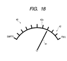
- a gauge corresponding to the amount of developer as shown, for example, in Fig. 18 of the accompanying drawings has been put into practical use.
- a developer remaining amount indicator 40 shown in Fig. 18 the user is informed of the remaining amount of developer by what portion of an indicating portion (gauge) 42 provided with a scale 42a from "Full” to "Empty” is pointed to by a pointer 41 moving in conformity with the remaining amount of developer.
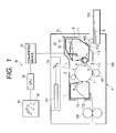
- Fig. 1 schematically shows the construction of an embodiment of an electrophotographic image forming apparatus according to the present invention.
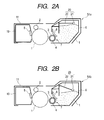
- Fig. 2A schematically shows the construction of an example of a high capacity process cartridge mountable in the electrophotographic image forming apparatus according to the present invention.
- Fig. 2B schematically shows the construction of an example of a low capacity process cartridge mountable in the electrophotographic image forming apparatus according to the present invention.
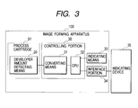
- Fig. 3 is a block diagram of an embodiment of the electrophotographic image forming apparatus according to the present invention.
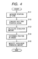
- Fig. 4 is a flowchart of an embodiment of the developer amount indicating operation of the present invention.
- Fig. 5 shows an embodiment of a developer amount indicating method according to the present invention.
- Fig. 6 shows a modification of the developer amount indicating method shown in Fig. 5.
- Fig. 7 schematically shows the construction of another embodiment of the electrophotographic image forming apparatus according to the present invention.
- Fig. 8 is a block diagram of another embodiment of the electrophotographic image forming apparatus according to the present invention.
- Fig. 9 is a flowchart of another embodiment of the developer amount indicating operation of the present invention.
- Figs. 10A and 10B show another embodiment of the developer amount indicating method according to the present invention, Fig. 10A showing a case where the high capacity process cartridge is mounted, and Fig. 10B showing a case where the low capacity process cartridge is mounted.
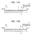
- Figs. 11A and 11B show a modification of the developer amount indicating method shown in Figs. 10A and 10B, Fig. 11A showing a case where the high capacity process cartridge is mounted, and Fig. 11B showing a case where the low capacity process cartridge is mounted.
- Figs. 12A and 12B show still another embodiment of the developer amount indicating method according to the present invention, Fig. 12A showing a case where the high capacity process cartridge is mounted, and Fig. 12B showing a case where the low capacity process cartridge is mounted.
- Figs. 13A and 13B show a modification of the developer amount indicating method shown in Figs. 12A and 12B, Fig. 13A showing a case where the high capacity process cartridge is mounted, and Fig. 13B showing a case where the low capacity process cartridge is mounted.
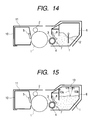
- Fig. 14 is a view for illustrating another embodiment of developer amount detecting means according to the present invention.
- Fig. 15 is a view for illustrating another embodiment of the developer amount detecting means according to the present invention.
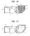
- Fig. 16 is a view for illustrating another embodiment of the developer amount detecting means according to the present invention.
- Fig. 17 is a view for illustrating end detecting means for the developer which can be provided in a developer container in accordance with the present invention.
- Fig. 18 shows an example of the developer amount indicating method according to the conventional art.
- a developer amount indicating method, an electrophotographic image forming apparatus and a process cartridge according to the present invention will hereinafter be described in greater detail with reference to the drawings.
- Embodiments which will hereinafter be described relate to a developer amount indicating method of successively detecting the remaining amount of developer in a developer container in the main body of an image forming apparatus capable of mounting a plurality of types of process cartridges differing in the fill amount of developer with respect to the developer container, and successively indicating the amount of developer in conformity with the types of the process cartridges, an electrophotographic image forming apparatus using the indicating method, and further a process cartridge detachably mountable with respect to the image forming apparatus.
- Fig. 1 is a schematic cross-sectional view showing a state in which a process cartridge 51 which will be described later is mounted in the main body 100 of the electrophotographic image forming apparatus.
- the electrophotographic image forming apparatus P (image forming apparatus) of the present embodiment has a drum-shaped electrophotographic photosensitive member (photosensitive drum) 1 rotatable in the direction indicated by the arrow, and an electrostatic latent image is formed on the surface of this photosensitive drum 1 by electrostatic latent image forming means. That is, the surface of the photosensitive drum 1 is uniformly charged in advance by a charging roller 2 as charging means. Subsequently, a laser beam L modulated in conformity with an image signal is outputted from a scanner unit 101 as exposing means having a laser and a polygon mirror correcting system lens. This lens beam L is reflected by a turn-back mirror 102 and applied onto the photosensitive drum 1. Thereby, an electrostatic latent image conforming to the application of the laser beam L is formed on the photosensitive drum 1. This electrostatic latent image is thereafter developed into a visible image, i.e., a toner image, by developing means 7.
- the developing means 7 has a developing roller 3 containing a stationary magnet 4 therein, and an elastic blade 8 for regulating the layer thickness of a developer carried on this developing roller 3.
- a developer container 6 as a developer containing portion is provided adjacent to the developing means 7.
- the developer stored in this developer container 6 is charged and borne and conveyed on the peripheral surface of the developing roller 3 with the rotation of this developing roller 3 indicated by the arrow.
- the developer adhering to the peripheral surface of the developing roller 3 has its layer thickness regulated by the elastic blade 8 and becomes a developer layer capable of developing.
- the electrostatic latent image on the photosensitive drum 1 is developed by the developer shifting from the developer layer conveyed with the rotation of the developing roller 3.
- a developing bias voltage comprising a DC voltage superimposed on an AC voltage is applied to the developing roller 3.
- the recording medium S contained in a recording medium containing cassette 103 is fed out by a recording medium supplying roller 103, conveying means 110, etc. in synchronism with the formation of the electrostatic latent image on the photosensitive drum 1. It is further conveyed to the opposed portion (transferring portion) of roller-shaped transferring means, i.e., a transferring roller 107, and the photosensitive drum 1 by a pair of registration rollers 111 in synchronism with the leading end of the toner image formed on the photosensitive drum 1. Then, the toner image is transferred onto the recording medium S by the transferring roller 107.
- roller-shaped transferring means i.e., a transferring roller 107
- the recording mediums S onto which the toner image has been transferred is conveyed to a fixing device 109, where the toner image is fixed on the recording medium S by heat and pressure and becomes a permanent image.
- the recording medium S on which the toner image is formed is discharged out of the image forming apparatus. Also, any developer residual on the photosensitive drum 1 is removed by cleaning means 5, and is contained in a removed developer container 10. The photosensitive drum 1 is then repetitively used for image formation.
- the process cartridge 51 is removably mounted in the main body 100 of the image forming apparatus through mounting means 112 as a mounting portion provided in the main body 100 of the image forming apparatus.
- the process cartridge 51 can be interchanged by a user himself when the developer stored in the developer container 6 has been depleted or when the photosensitive drum 1 has come to its life.
- the image forming apparatus has a developer amount detecting device for successively detecting the remaining amount of developer in the developer container 6. That is, the process cartridge 51 is provided with developer amount detecting means 20 for successively detecting the amount of developer remaining in the developer container 6, and the main body 100 of the image forming apparatus is provided with a controlling portion 30 for processing an electrical signal, i.e., developer amount information, outputted by the developer amount detecting means 20 in conformity with the amount of developer in the developer container 6.
- an electrical signal i.e., developer amount information
- the controlling portion 30 has converting means 31 for converting the developer amount information in the developer container 6 obtained by the developer amount detecting means 20 in the present embodiment which will be described later into an electrical signal, and a CPU (central processing unit) 32 for causing the remaining amount of developer to be successively indicated on developer amount indicating means 33 on the basis of that signal as will be described later.
- converting means 31 for converting the developer amount information in the developer container 6 obtained by the developer amount detecting means 20 in the present embodiment which will be described later into an electrical signal
- a CPU (central processing unit) 32 for causing the remaining amount of developer to be successively indicated on developer amount indicating means 33 on the basis of that signal as will be described later.
- developer amount detecting means 20 use can be made of any means that can successively detect the amount of developer remaining in the developer container 6.
- the developer amount detecting means 20 use is made of a method of detecting the position of contacting means 21 disposed on the surface of the upper portion of the developer contained in the developer container 6 by an arm 22 which is following means coupled to the contacting means 21. That is, with the consumption of the developer, the contacting means 21 is always disposed on the surface of the upper portion of the developer by gravity, and the position of the contacting means 21 is detected through the arm 22 pivotally moved following the movement of the contacting means 21.
- a high capacity cartridge 51a and a low capacity cartridge 51b are mounted in the main body 100 of the image forming apparatus as a plurality of types of process cartridges differing in the fill amount of developer stored in the developer container 6.
- the high capacity and low capacity process cartridges 51a and 51b are similar in construction to each other with the exception that they differ in the fill amount of developer stored in the developer container 6, i.e., the fill amount when they are new, the present invention is not restricted thereto, but the shape or the like of the housing of the developer container 6 may be changed as required.
- the amounts of developer stored in the respective process cartridges 51a and 51b when they are new are 500 g for the high capacity cartridge 51a and 300 g for the low capacity cartridge 51b. Also, the construction and setting of the developer amount detecting means 20 are entirely the same for both process cartridges 51a and 51b.
- Fig. 3 shows a block diagram of the present embodiment.
- the position of the contacting means 21 detected by the arm 22 of the developer amount detecting means 20 is converted into an electrical signal by converting means 31 and the electrical signal is sent to a CPU 32. Then, calculation is effected by the CPU 32 so that the electrical signal may become a signal conforming to the amount of developer in the developer container 6, and a signal for indicating the remaining amount of developer is sent to developer amount indicating means 33.
- the signal of the CPU 32 may be sent to an outside indicating device 35 through an interface portion 34 and indicated on the screen of the outside device.
- an outside indicating device 35 in an image forming apparatus connected, for example, to a personal computer network, mention may be made of the screen or the like of a host computer connected to the image forming apparatus.
- Fig. 4 shows a flowchart of the remaining amount indicating operation in the present embodiment.
- the position of the arm 22 is first detected by the developer amount detecting means 20 (S101). Next, the position of the arm 22 is converted into a position signal by the converting means 31 (S102). The position signal is sent to the CPU 32, by which the remaining amount of developer is calculated (S103). The position in a gauge indicated by a pointer is determined in conformity with the amount of developer thus found (S104). Thereafter, the remaining amount of developer is indicated on the indicating means (S105).
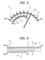
- Fig. 5 shows an example of the developer remaining amount indication 40 on the developer amount indicating means 33 in the present embodiment.
- gauges indicating portions
- graduations 43a for high capacity and graduations 44a for low capacity respectively, i.e., a gauge 43 for high capacity and a gauge 44 for low capacity, in order to indicate the remaining amounts of developer in the developer containers 6 of the high capacity cartridge 51a and the low capacity cartridge 51b as a plurality of types of process cartridges differing in the fill amount of developer in the developer container 6.
- the user reads the graduations 43a of the gauge 43 for high capacity when the process cartridge mounted in the main body 100 of the image forming apparatus is the high capacity cartridge 51a. Also, the user reads the graduations 44a of the gauge 44 for low capacity when the low capacity cartridge 51b is mounted.
- a pointer 41 moves in conformity with the movement of the surface of the upper portion of the developer in the developer container 6.
- the pointer 41 is controlled as follows by the CPU 32. First, the pointer 41 points to a portion A when the amount of developer is 500 g, and points to a portion B when the amount of developer is 300 g. Further, the pointer 41 points to a portion C when the developer is absent.
- the pointer 41 is indicated at the position of "Full" in the gauge 43 for high capacity, and can successively indicate the amount of developer until the developer runs short and the pointer 41 points to the position of "Empty".
- the pointer 41 is indicated at the position of "Full" in the gauge 44 for low capacity, and can successively indicate the amount of developer until the developer runs short and the pointer 41 points to the position of "Empty".
- Fig. 6 shows a modification of the present embodiment.
- a bar 45 points to positions in gauges 43 and 44 to thereby indicate the amounts of developer in the developer containers 6.
- the plurality of types of gauges 43 and 44 are indicated in conformity with the types of the process cartridges 51 and therefore, as in the case of the indicating method shown in Fig. 5, the effect of the present invention can be obtained.
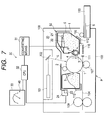
- Fig. 7 schematically shows the construction of another embodiment of the image forming apparatus capable of detachably mounting a process cartridge, and shows a state in which the process cartridge 52 of the present embodiment is mounted.
- the constructions of the process cartridge 52 and the image forming apparatus in the present embodiment are basically similar to those of Embodiment 1 and therefore, members similar in construction and function to those in Embodiment 1 are given similar reference numerals and need not be described in detail.
- the process cartridge 52 has, in addition to the construction of the process cartridges 51 described in Embodiment 1, a discriminating member 23 as an informing portion for indicating the type of the process cartridge 52 by the fill amount of developer contained in the developer container 6, i.e., the fill amount when the process cartridge 52 is new.
- the main body 100 of the image forming apparatus is provided with type detecting means 24 as a detecting portion.
- This type detecting means 24 in a state in which the process cartridge 52 is mounted in the main body 100 of the image forming apparatus, reads the fill amount of developer in the developer container 6 indicating by the discriminating member 23 provided on the process cartridge 52, i.e., information regarding the type of the process cartridge 52.
- the indication of the remaining amount of developer on the developer amount indicating means 33 is changed over in conformity with the fill amount of developer in the process cartridge 52 read by the type detecting means 24.
- the type detecting means 24 provided in the main body 100 of the image forming apparatus reads the content of the discriminating member 23 provided on the process cartridge 52, and sends to the CPU 32 information indicating that the process cartridge is a high capacity cartridge 52a or a low capacity cartridge 52b, for example, in the present embodiment, as the information regarding the fill amount of developer in the developer container 6.
- the CPU 32 discriminates the type of the mounted process cartridge 52 by the information sent thereto.
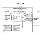
- Fig. 8 shows a block diagram of Embodiment 2.
- the developer amount detecting means 20 as a detecting signal outputting portion provided in the process cartridge 52 detects the amount of developer and delivers the developer amount information to the converting means 31 provided in the main body 100 of the image forming apparatus. This information is then converted into an electrical signal by the converting means 31, whereafter the electrical signal is inputted to the CPU 32. Also, the cartridge discrimination information of the cartridge discriminating member 23 provided on the process cartridge sends information indicative of the type of the cartridge to the CPU 32 through the type detecting means 24. The CPU 32 sends the signal of the developer amount indication 40 from both of the detection signal of the amount of developer and the signal indicative of the type of the cartridge 52 to the developer amount indicating means 33.
- the signal of the developer amount indication 40 may be sent to the outside indicating device 35 through the interface portion 34 and indicated on the screen of the outside indicating device.
- the discriminating member 23 provided on the process cartridge 52 and the type detecting means 24 provided in the main body 100 of the image forming apparatus mention may be made of a construction in which projections provided on the discriminating member 23 and of which the number and presence are varied by the type of the process cartridge 52 push a switch provided on the type detecting means 24. Besides this, use can be made of conventional means such as the reading of an optical signal, or providing an electrical memory as the discriminating member 23 on the process cartridge 52, and the type detecting means 24 in the main body 100 of the image forming apparatus reading information stored in this memory.
- Fig. 9 shows a flowchart of the remaining amount indicating operation in Embodiment 2.
- Embodiment 2 will hereinafter be described with reference to Fig. 9.
- a cartridge discriminating signal is first read (S201), and the capacity of the cartridge being mounted is determined (S202). After the capacity has been determined, the graduations for the indication of the remaining amount conforming to the capacity and the content of the indication are determined (S203).
- the position of the arm 22 is detected by the developer amount detecting means 20 (S204).
- the position of the arm 22 is converted into a position signal by the converting means 31 (S205).
- the position signal is sent to the CPU 32, by which the remaining amount of developer is calculated (S206).
- the position in the gauge indicated by the pointer is determined in conformity with the amount of developer thus found (S207). Thereafter, the graduations for the indication of the remaining amount and the content of the indication determined at S203 and the position in the gauge determined at S207 are combined together and the remaining amount of developer is indicated on the indicating means (S208).
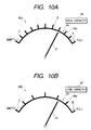
- Figs. 10A and 10B show specific examples of developer remaining amount indications 40a and 40b in the present embodiment.
- description will be made of cases where as a plurality of types of process cartridges 52 differing in the fill amount of developer in the developer container 6, as in Embodiment 1, a high capacity cartridge 52a of which the fill amount of developer in the developer container 6 is 500 g and a low capacity cartridge 52b of which the fill amount of developer in the developer container 6 is 300 g are mounted in the main body 100 of the image forming apparatus.
- Fig. 10A shows the developer remaining amount indication 40a when the process cartridge 52 mounted in the main body 100 of the image forming apparatus has been discriminated as being the high capacity cartridge 52a
- Fig. 10B shows the developer remaining amount indication 40b when the process cartridge 52 mounted in the main body 100 of the image forming apparatus has been discriminated as being the low capacity cartridge 52b.
- gauges (indicating portions) 43 and 44 for high capacity and low capacity, respectively, provided with graduations 43a and 44a from "Full" indicative of the fill amount of developer when the cartridges are new to "Empty" indicative of the absence of the developer are indicated.
- the gauges 43 and 44 are divided for 50 g each of developer by the graduations 43a and 44a, respectively, and the sizes of the wholes of the gauges 43 and 44 are the same. Accordingly, a graduation of the gauge is enlarged and indicated when the low capacity cartridge 52b is mounted.
- the pointer 41 moves in conformity with the movement of the surface of the upper portion of the developer in the developer container 6.
- the pointer 41 is controlled as follows by the CPU 32. First, the pointer 41 points to a position A in the gauge 43 for high capacity when the amount of developer is 500 g, and points to positions B in the gauges 43 and 44 for high capacity and low capacity, respectively, when the amount of developer is 300 g.
- the pointer 41 points to positions C in the gauges 43 and 44 for high capacity and low capacity, respectively, when the developer is absent.
- the indication is controlled by the CPU 32 so that the width of the variation of the pointer 41 pointing to the gauges 43 and 44 for high capacity and low capacity, respectively, by the amount of developer may differ depending on the type of the process cartridge 52 mounted in the main body 100 of the image forming apparatus.
- the type indications 46 and 47 of the process cartridges 52 such as "High Capacity” when the example, the high capacity cartridge 52a is mounted, and “Low Capacity” when the low capacity cartridge 52b is mounted may be effected.
- the colors of the gauges may be made to differ between the gauge 43 for high capacity and the gauge 44 for low capacity.
- Figs. 11A and 11B show a modification of the present embodiment.
- bars 45 point to positions in the gauges 43 and 44, and indicate the amounts of developer in the developer containers 6.
- an effect similar to that in the case of the indicating method shown in Figs. 10A and 10B can be obtained.
- the discriminating member 23 is provided on the process cartridge 52 and the type detecting means 24 is provided in the main body 100 of the image forming apparatus and the developer remaining amount indications 40a and 40b on the developer amount indicating means 33 are automatically changed over
- a system in which a manually operated changeover switch is provided on the main body 100 of the image forming apparatus and the user himself operates the switch to thereby change over the indication can also be adopted as the type detecting means 24.
- the process cartridge 52 has a discriminating member 23 indicative of the type of the process cartridge 52 by the fill amount of developer contained in the developer container 6, i.e., the fill amount when the process cartridge is new.
- type detecting means 24 is provided in the main body 100 of the image forming apparatus, and this type detecting means 24, in a state in which the process cartridge 52 is mounted in the main body 100 of the image forming apparatus, reads information regarding the type of the process cartridge 52 indicated by the discriminating member 23 provided on the process cartridge 52.
- the CPU 32 as controlling means changes over the developer remaining amount indications 40a and 40b as indicating portions automatically indicated on the developer amount indicating means 33 so as to conform to the type of the mounted process cartridge 52.
- the position pointed to by the pointer 41 in conformity with the amount of developer remaining in the process cartridge 52 is made the same, whereby the indication is made easy for the user to confirm the remaining amount of developer.
- Figs. 12A and 12B show a specific example of the developer amount indicating method in the present embodiment.
- description will be made of cases where as a plurality of types of process cartridges 52, as in Embodiment 2, a high capacity cartridge 52a of which the fill amount of developer in the developer container 6 is 500 g and a low capacity cartridge 52b of which the fill amount of developer is 300 g are mounted in the main body 100 of the image forming apparatus.
- Fig. 12A shows the developer remaining amount indication 40a when the process cartridge 52 mounted in the main body 100 of the image forming apparatus has been discriminated as being the high capacity cartridge 52a
- Fig. 12B shows the developer remaining amount indication 40b when the process cartridge 52 mounted in the main body 100 of the image forming apparatus has been discriminated as being the low capacity cartridge 52b.
- gauges 43 and 44 for high capacity and low capacity are indicated, respectively.
- the widths of graduations corresponding to the amounts of decrease in the developer are the same and the positions of "Empty" are the same. Accordingly, the gauge 43 for high capacity and the gauge 44 for low capacity differ in only the position of "Full" from each other.
- the pointer 41 moves in conformity with the movement of the surface of the upper portion of the developer in the developer container 6, and points to a position A in the gauge 43 for high capacity when the amount of developer is 500 g, and points to positions B in the gauges 43 and 44 for high capacity and low capacity, respectively, when the amount of developer is 300 g, and points to positions C in the gauges 43 and 44 for high capacity and low capacity, respectively, when the developer is absent.
- the CPU 32 discriminates the type of the mounted process cartridge 52, and automatically changes over the developer remaining amount indication 40 so that irrespective of the discriminated type of the process cartridge 52, the positions pointed to by the pointer 41 may become the same in conformity with the amount of developer.
- the type indications 46 and 47 of the process cartridge 52 such as "High Capacity” when the high capacity cartridge 52a has been mounted, and “Low Capacity” when the low capacity cartridge 52b has been mounted may be effected.
- the gauge 43 for high capacity and the gauge 44 for low capacity may be made to differ in the color of the gauge from each other.
- Figs. 13A and 13B show a modification of the present embodiment.
- bars 45 point to positions in the gauges 43 and 44, and indicate the amounts of developer in the developer containers 6.
- an effect similar to that in the case of the indicating method shown in Figs. 12A and 12B can be obtained.
- a discriminating member 23 is provided on the process cartridge 52 and type detecting means 24 is provided in the main body 100 of the image forming apparatus and the developer remaining amount indications 40a and 40b are automatically changed over by the developer amount indicating means 33
- a system in which a manually operated changeover switch is provided on the main body 100 of the image forming apparatus and the user himself operates the switch to thereby change over the indication can be adopted as the type detecting means 24.
- the developer amount indicating means 33 for indicating the developer remaining amount indications 40a and 40b may be an indicating portion such as an LCD display provided on the main body of the image forming apparatus, but for example, in an image forming apparatus connected to a personal computer network, it may be a system in which the developer remaining amount indications 40a and 40b are indicated on the screen of an outside device such as the screen of a host computer connected to the image forming apparatus. By doing so, the user can know the remaining amount of developer while operating the host computer.
- the present embodiment even when a plurality of types of process cartridges 52a and 52b differing in the fill amount of developer in the developer container 6 are mounted, it is possible to effect the indication of the amount of developer which is comprehensible to the user and particularly, the widths of graduations in the graduations 43a and 44b of the gauges 43 and 44 are equal to one another and therefore, the visual perceptibility of the remaining amount of developer is good even if the types of the process cartridges differ.
- the developer amount detecting means 20 use is made of a system in which the position of the contacting means 21 disposed on the surface of the upper portion of the developer in the developer container 6 and moving with the movement of the surface of the upper portion of the developer is detected by the arm 22 which is following means.
- the present invention is not restricted to this system, but as the developer amount detecting means 20 according to the present invention, use can be made of any means that can successively detect the amount of developer remaining in the developer container 6.
- an effect similar to that of the above-described Embodiments 1 to 3 can also be obtained when use is made of any one of the following systems:
- the developer amount detecting means 20 for successively detecting the amount of developer in the developer container 6, but more preferably, as shown in Fig. 17, an antenna rod, i.e., an electrode rod 9, as developer end detecting means extending by a predetermined length in the lengthwise direction of the developing sleeve 3 of the developing means 7 at a predetermined interval from the developing sleeve 3 is further provided outside the developer amount detecting means 20, and any change in the electrostatic capacity between the developing sleeve 3 and the electrode rod 9 can be detected to thereby detect the end of the developer.
- an antenna rod i.e., an electrode rod 9
- any change in the electrostatic capacity between the developing sleeve 3 and the electrode rod 9 can be detected to thereby detect the end of the developer.
- an indicating portion selected in conformity with the type of one of the plurality of types of cartridges which is mounted in the main body (100) of the electrophotographic image forming apparatus (P) is indicated, and the detected amount of developer in the cartridge mounted in the main body (100) of the electrophotographic image forming apparatus is successively indicated by the use of the indicating portion.
- a developer amount successively indicating method used in an electrophotographic image forming apparatus capable of detachably mounting a plurality of types of cartridges differing in the fill amount of developer (t)
- indicating portions conforming to the types of the cartridges are indicated correspondingly to the types
- the detected amount of developer in the cartridge mounted in the main body of the electrophotographic image forming apparatus is successively indicated by the use of the indicated indicating portions.
- the indicating portions have graduations (43a, 44a), and in the graduations (43a, 44a), a graduation indicates the same amount of developer, irrespective of the types of the cartridges (e.g. process cartridges 51a, 51b), and the intervals between adjacent ones of the graduations are equal.
- the indicating portions (gauges 43, 44, developer amount indication 40) differ in indicating color in conformity with the types of the cartridges.
- the indicating portions (gauges 43, 44, developer amount indication 40) have developer amount indicating areas from “Full” to “Empty", and the indicating method successively indicates the detected amount of developer in the cartridge mounted in the main body of the electrophotographic image forming apparatus from “Full” to "Empty".
- the indicating portions are indicated on the main body (100) of the electrophotographic image forming apparatus.
- the indicating portions are indicated on the display of a host computer connected to the main body (100) of the electrophotographic image forming apparatus.
- the type of the cartridge (51a, 51b) mounted in the main body (100) of the electrophotographic image forming apparatus is indicated.
- the cartridge is a process cartridge (51a, 51b) integrally having a developer supplying container (not shown) containing therein a developer to be supplied to the main body (100) of the electrophotographic image forming apparatus, or an electophotographic photosensitive member (1) and process means (at least one of charging means 2, cleaning means 5 and developing means 7) acting on the electrophotographic photosensitive member, and detachably mountable in the main body (100) of the electrophotographic image forming apparatus.
- a developer supplying container not shown
- process means at least one of charging means 2, cleaning means 5 and developing means
- the process means is at least one of the developing means 7 for developing the electrostatic latent image formed on the electrophotographic photosensitive member (1), the charging means (2) for charging the electrophotographic photosensitive member (1), and the cleaning means (5) for removing any developer residual on the electrophotographic photosensitive member (1).
- an informing portion (discriminating member 23) each cartridge has in conformity with its type is detected by a detecting portion (type detecting means 24) which the main body (100) of the electrophotographic image forming apparatus has.
- the indicating portions are selected and indicated on the basis of the result of the detection.
- An electrophotographic image forming apparatus (P) for forming an image on a recording medium (S) which is capable of detachably mounting a cartridge (e.g. process cartridge 51a, 51b) having a developer containing portion (developer container 6) containing therein a developer (t) to be used to develop an electrostatic latent image formed on an electrophotographic photosensitive member (1) has:
- An electrophotographic image forming apparatus for forming an image on a recording medium (S) which is capable of detachably mounting a cartridge (e.g. process cartridge 51a, 51b) having a developer containing portion (developer container 6) containing therein a developer (t) to be used to develop an electrostatic latent image formed on an electrophotographic photosensitive member (1) has:
- a process cartridge (51a, 51b) detachably mountable in the main body of an electrophotographic image forming apparatus has:
- the term "Full” indicates an amount corresponding to the initial fill amount of the developer in the developer container 6, or an amount intended as the initial fill amount, i.e., a maximum amount detectable by the developer amount detecting means 20, and the indication itself is not restricted thereto. Accordingly, as a matter of course, it is also possible to indicate, for example, numerical values indicative of the amounts of developer, percentages representative of the use rates, etc. on the gauges.
- the present invention is not restricted to successively detecting the amount of developer over the entire area of 100% to 0%, but design may be made such that the amount of developer is successively detected, for example, over an area of 50% to 0% (Empty).
- the term "Empty" indicates the detectable minimum amount of the developer in the developer container 6, i.e., such an amount that the developer container 6 is substantially empty, and includes also a state in which the developer is present in the developer container 6, but the amount of developer is small to such a degree that may spoil image dignity (development dignity).
- the present invention does not restrict the indication itself thereto, but as a matter of course, it is also possible to indicate, for example, numerical values indicative of the amounts of developer, percentages representative of the use rates, etc. on the gauges.
- a developer amount indicating method As described above, according to the present invention, there can be provided a developer amount indicating method, an electrophotographic image forming apparatus and a process cartridge which can comprehensibly indicate the amount of developer.
- a developer amount indicating method which can successively indicate the amount of developer in conformity with the types of the process cartridges, an electrophotographic image forming apparatus using the indicating method, and a process cartridge detachably mountable in the main body of the image forming apparatus.
Abstract
Description
- This invention relates to a developer amount indicating method, an electrophotographic image forming apparatus and a process cartridge.
- Here, the electrophotographic image forming apparatus is an apparatus for forming an image on a recording medium by the use of the electrophotographic image forming process. It covers, for example, an electrophotographic copier, an electrophotographic printer (such as an LED printer or a laser beam printer), an electrophotographic facsimile apparatus and an electrophotographic word processor.
- Also, the process cartridge refers to at least one of charging means, developing means and cleaning means as process means and an electrophotographic photosensitive member integrally made into a cartridge which is detachably mountable to the main body of the electrophotographic image forming apparatus. Or it refers to developing means as process means and an electrophotographic photosensitive member integrally made into a cartridge which is detachably mountable to the main body of the electrophotographic image forming apparatus.
- In an electrophotographic image forming apparatus, there has heretofore been adopted a process cartridge system whereby an electrophotographic photosensitive member and process means acting on the electrophotographic photosensitive member are integrally made into a cartridge which is detachably mountable to the main body of the electrophotographic image forming apparatus. According to this process cartridge system, the maintenance of the apparatus can be done by a user himself without resorting to a serviceman and therefore, the operability of the apparatus can be markedly improved. So, this process cartridge system is widely used in electrophotographic image forming apparatus.
- In the image forming apparatus of such a process cartridge type, as a standard for the user to effect the interchange of the process cartridge, there is the function of detecting that the remaining amount of developer in a developer container provided in the process cartridge has assumed a predetermined value or less, and informing the user of it.
- Also, in order to improve the convenience to the user, the function of successively detecting the remaining amount of developer and informing the user of the remaining amount of developer by a gauge corresponding to the amount of developer as shown, for example, in Fig. 18 of the accompanying drawings has been put into practical use. In a developer remaining
amount indicator 40 shown in Fig. 18, the user is informed of the remaining amount of developer by what portion of an indicating portion (gauge) 42 provided with ascale 42a from "Full" to "Empty" is pointed to by apointer 41 moving in conformity with the remaining amount of developer. - In recent years, a plurality of types of process cartridges differing in the amount of developer filling a developer container from one another have been prepared so that the user can select them. Image forming apparatuses capable of mounting such a plurality of types of process cartridges have been commercialized.
- Usually, when the amount of developer in a process cartridge is to be detected, the absolute amount of developer is detected. Therefore, there is conceivable the possibility that distinction cannot be made between a case where a new process cartridge small in the amount of developer filling a developer container (hereinafter referred to as the "low capacity process cartridge") has been mounted and a case where a process cartridge large in the amount of developer filling a developer container (hereinafter referred to as the "high capacity cartridge") and having become smaller in the amount of developer by consumption has been mounted.
- In the image forming apparatus on which such a plurality of types of process cartridges are mounted, when the user is informed of the remaining amount of developer by the conventional gauge system shown in Fig. 18, the following problems would occur to mind. When for example, the position of "Full" is adjusted so as to indicate the fullness of the small capacity cartridge with the developer, if the high capacity cartridge is mounted, the
pointer 41 continues to stay at the position of "Full" in thegauge 42 until the developer is consumed up to an amount corresponding to the fullness of the low capacity cartridge with the developer. Accordingly, the problem that in the meantime, the amount of developer cannot be indicated successively would occur to mind. - Also, when the position of "Full" shown in Fig. 18 is adjusted so as to indicate the fullness of the high capacity cartridge with the developer, if the low capacity cartridge is mounted, it would occur to mind that in spite of the cartridge being new, the
pointer 41 points to a position less than the "Full" in thegauge 42. - It is an object of the present invention to provide a developer amount indicating method, an electrophotographic image forming apparatus and a process cartridge which can comprehensibly indicate the amount of developer.
- It is another object of the present invention to provide, in an image forming apparatus capable of mounting a plurality of types of process cartridges differing in the fill amount of developer with respect to a developer containing portion, a developer amount indicating method capable of successively indicating the amount of developer in conformity with the types of the process cartridges, an electrophotographic image forming apparatus using the indicating method, and a process cartridge detachably mountable with respect to the main body of the image forming apparatus.
- It is another object of the present invention to provide a developer amount indicating method, an electrophotographic image forming apparatus and a process cartridge capable of successively effecting the indication of the amount of developer comprehensible to an operator even when a plurality of types of process cartridges differing in the fill amount of developer with respect to a developer containing portion are mounted.
- It is another object of the present invention to provide, in a plurality of types of process cartridges differing in the fill amount of developer in a developer containing portion, a developer amount indicating method, an electrophotographic image forming apparatus and a process cartridge capable of successively indicating the remaining amount of developer from "Full" to "Empty".
- It is another object of the present invention to provide a developer amount successively indicating method used in an electrophotographic image forming apparatus capable of detachably mounting a plurality of types of cartridges differing in the fill amount of developer, wherein an indicating portion selected in conformity with the type of one of the plurality of kinds of cartridges which is mounted in the main body of the electrophotographic image forming apparatus is indicated, and the detected amount of developer in the cartridge mounted in the main body of the electrophotographic image forming apparatus is successively indicated by the use of the indicating portion, an electrophotographic image forming apparatus using the indicating method, and a process cartridge detachably mounted in the electrophotographic image forming apparatus.
- It is another object of the present invention to provide a developer amount successively indicating method used in an electrophotographic image forming apparatus capable of delatachably mounting a plurality of types of cartridges differing in the fill amount of developer, wherein indicating portions conforming to the type of the cartridges are indicated correspondingly to the types, and the detected amount of developer in the cartridge mounted in the main body of the electrophotographic image forming apparatus is successively indicated by the use of the indicated indicating portions, an electrophotographic image forming apparatus using the indicating method, and a process cartridge detachably mountable in the electrophotographic image forming apparatus.
- These and other objects, features and advantages of the present invention will become more apparent upon consideration of the following description of the preferred embodiments of the present invention taken in conjunction with the accompanying drawings.
- Fig. 1 schematically shows the construction of an embodiment of an electrophotographic image forming apparatus according to the present invention.
- Fig. 2A schematically shows the construction of an example of a high capacity process cartridge mountable in the electrophotographic image forming apparatus according to the present invention.
- Fig. 2B schematically shows the construction of an example of a low capacity process cartridge mountable in the electrophotographic image forming apparatus according to the present invention.
- Fig. 3 is a block diagram of an embodiment of the electrophotographic image forming apparatus according to the present invention.
- Fig. 4 is a flowchart of an embodiment of the developer amount indicating operation of the present invention.
- Fig. 5 shows an embodiment of a developer amount indicating method according to the present invention.
- Fig. 6 shows a modification of the developer amount indicating method shown in Fig. 5.
- Fig. 7 schematically shows the construction of another embodiment of the electrophotographic image forming apparatus according to the present invention.
- Fig. 8 is a block diagram of another embodiment of the electrophotographic image forming apparatus according to the present invention.
- Fig. 9 is a flowchart of another embodiment of the developer amount indicating operation of the present invention.
- Figs. 10A and 10B show another embodiment of the developer amount indicating method according to the present invention, Fig. 10A showing a case where the high capacity process cartridge is mounted, and Fig. 10B showing a case where the low capacity process cartridge is mounted.
- Figs. 11A and 11B show a modification of the developer amount indicating method shown in Figs. 10A and 10B, Fig. 11A showing a case where the high capacity process cartridge is mounted, and Fig. 11B showing a case where the low capacity process cartridge is mounted.
- Figs. 12A and 12B show still another embodiment of the developer amount indicating method according to the present invention, Fig. 12A showing a case where the high capacity process cartridge is mounted, and Fig. 12B showing a case where the low capacity process cartridge is mounted.
- Figs. 13A and 13B show a modification of the developer amount indicating method shown in Figs. 12A and 12B, Fig. 13A showing a case where the high capacity process cartridge is mounted, and Fig. 13B showing a case where the low capacity process cartridge is mounted.
- Fig. 14 is a view for illustrating another embodiment of developer amount detecting means according to the present invention.
- Fig. 15 is a view for illustrating another embodiment of the developer amount detecting means according to the present invention.
- Fig. 16 is a view for illustrating another embodiment of the developer amount detecting means according to the present invention.
- Fig. 17 is a view for illustrating end detecting means for the developer which can be provided in a developer container in accordance with the present invention.
- Fig. 18 shows an example of the developer amount indicating method according to the conventional art.
- A developer amount indicating method, an electrophotographic image forming apparatus and a process cartridge according to the present invention will hereinafter be described in greater detail with reference to the drawings.
- Embodiments which will hereinafter be described relate to a developer amount indicating method of successively detecting the remaining amount of developer in a developer container in the main body of an image forming apparatus capable of mounting a plurality of types of process cartridges differing in the fill amount of developer with respect to the developer container, and successively indicating the amount of developer in conformity with the types of the process cartridges, an electrophotographic image forming apparatus using the indicating method, and further a process cartridge detachably mountable with respect to the image forming apparatus.
- Reference is first had to Fig. 1 to describe an embodiment of an electrophotographic image forming apparatus capable of mounting a process cartridge using an embodiment of the present invention. In the present embodiment, the electrophotographic image forming apparatus is a laser beam printer for forming an image on a recording medium S such as recording paper, an OHP sheet or cloth by the electrophotographic image forming process. Particularly, Fig. 1 is a schematic cross-sectional view showing a state in which a
process cartridge 51 which will be described later is mounted in themain body 100 of the electrophotographic image forming apparatus. - As shown in Fig. 1, the electrophotographic image forming apparatus P (image forming apparatus) of the present embodiment has a drum-shaped electrophotographic photosensitive member (photosensitive drum) 1 rotatable in the direction indicated by the arrow, and an electrostatic latent image is formed on the surface of this
photosensitive drum 1 by electrostatic latent image forming means. That is, the surface of thephotosensitive drum 1 is uniformly charged in advance by a chargingroller 2 as charging means. Subsequently, a laser beam L modulated in conformity with an image signal is outputted from ascanner unit 101 as exposing means having a laser and a polygon mirror correcting system lens. This lens beam L is reflected by a turn-back mirror 102 and applied onto thephotosensitive drum 1. Thereby, an electrostatic latent image conforming to the application of the laser beam L is formed on thephotosensitive drum 1. This electrostatic latent image is thereafter developed into a visible image, i.e., a toner image, by developingmeans 7. - That is, the developing
means 7 has a developingroller 3 containing astationary magnet 4 therein, and anelastic blade 8 for regulating the layer thickness of a developer carried on this developingroller 3. Also, adeveloper container 6 as a developer containing portion is provided adjacent to the developingmeans 7. The developer stored in thisdeveloper container 6 is charged and borne and conveyed on the peripheral surface of the developingroller 3 with the rotation of this developingroller 3 indicated by the arrow. Then, the developer adhering to the peripheral surface of the developingroller 3 has its layer thickness regulated by theelastic blade 8 and becomes a developer layer capable of developing. The electrostatic latent image on thephotosensitive drum 1 is developed by the developer shifting from the developer layer conveyed with the rotation of the developingroller 3. Usually, a developing bias voltage comprising a DC voltage superimposed on an AC voltage is applied to the developingroller 3. - On the other hand, the recording medium S contained in a recording
medium containing cassette 103 is fed out by a recordingmedium supplying roller 103, conveying means 110, etc. in synchronism with the formation of the electrostatic latent image on thephotosensitive drum 1. It is further conveyed to the opposed portion (transferring portion) of roller-shaped transferring means, i.e., a transferringroller 107, and thephotosensitive drum 1 by a pair ofregistration rollers 111 in synchronism with the leading end of the toner image formed on thephotosensitive drum 1. Then, the toner image is transferred onto the recording medium S by the transferringroller 107. - The recording mediums S onto which the toner image has been transferred is conveyed to a
fixing device 109, where the toner image is fixed on the recording medium S by heat and pressure and becomes a permanent image. - Thereafter, the recording medium S on which the toner image is formed is discharged out of the image forming apparatus. Also, any developer residual on the
photosensitive drum 1 is removed by cleaningmeans 5, and is contained in a removeddeveloper container 10. Thephotosensitive drum 1 is then repetitively used for image formation. - As shown in Fig. 1, in the present embodiment, the
photosensitive drum 1, the charging means (charging roller) 2, the developingmeans 7 provided with the developingroller 3 and theelastic blade 8, and the cleaning means 5 as process means acting on thephotosensitive drum 1, and further thedeveloper container 6 as the developer containing portion formed integrally with the developingmeans 7, and the removeddeveloper container 10 formed integrally with the cleaning means 5 are integrally coupled together by aframe member 11 and thereby made into aprocess cartridge 51. - Also, the
process cartridge 51 is removably mounted in themain body 100 of the image forming apparatus through mounting means 112 as a mounting portion provided in themain body 100 of the image forming apparatus. As previously described, theprocess cartridge 51 can be interchanged by a user himself when the developer stored in thedeveloper container 6 has been depleted or when thephotosensitive drum 1 has come to its life. - According to the present embodiment, the image forming apparatus has a developer amount detecting device for successively detecting the remaining amount of developer in the
developer container 6. That is, theprocess cartridge 51 is provided with developer amount detecting means 20 for successively detecting the amount of developer remaining in thedeveloper container 6, and themain body 100 of the image forming apparatus is provided with a controllingportion 30 for processing an electrical signal, i.e., developer amount information, outputted by the developer amount detecting means 20 in conformity with the amount of developer in thedeveloper container 6. - According to the present embodiment, the controlling
portion 30 has convertingmeans 31 for converting the developer amount information in thedeveloper container 6 obtained by the developer amount detecting means 20 in the present embodiment which will be described later into an electrical signal, and a CPU (central processing unit) 32 for causing the remaining amount of developer to be successively indicated on developer amount indicating means 33 on the basis of that signal as will be described later. - As the developer
amount detecting means 20, use can be made of any means that can successively detect the amount of developer remaining in thedeveloper container 6. - In the present embodiment, as shown in Fig. 1, as the developer
amount detecting means 20, use is made of a method of detecting the position of contactingmeans 21 disposed on the surface of the upper portion of the developer contained in thedeveloper container 6 by anarm 22 which is following means coupled to the contactingmeans 21. That is, with the consumption of the developer, the contactingmeans 21 is always disposed on the surface of the upper portion of the developer by gravity, and the position of the contactingmeans 21 is detected through thearm 22 pivotally moved following the movement of the contactingmeans 21. - Description will now be made of a method of successively detecting the amount of developer in the
developer container 6 and a method of indicating it, in the present embodiment. - In the present embodiment, description will be made of cases where as shown in Figs. 2A and 2B, two types of process cartridges, i.e., a
high capacity cartridge 51a and alow capacity cartridge 51b are mounted in themain body 100 of the image forming apparatus as a plurality of types of process cartridges differing in the fill amount of developer stored in thedeveloper container 6. - While the high capacity and low
capacity process cartridges developer container 6, i.e., the fill amount when they are new, the present invention is not restricted thereto, but the shape or the like of the housing of thedeveloper container 6 may be changed as required. - In the present embodiment, the amounts of developer stored in the
respective process cartridges high capacity cartridge 51a and 300 g for thelow capacity cartridge 51b. Also, the construction and setting of the developeramount detecting means 20 are entirely the same for bothprocess cartridges - Fig. 3 shows a block diagram of the present embodiment.
- According to the present embodiment, the position of the contacting means 21 detected by the
arm 22 of the developeramount detecting means 20 is converted into an electrical signal by convertingmeans 31 and the electrical signal is sent to aCPU 32. Then, calculation is effected by theCPU 32 so that the electrical signal may become a signal conforming to the amount of developer in thedeveloper container 6, and a signal for indicating the remaining amount of developer is sent to developeramount indicating means 33. - Also, as shown in Fig. 3, the signal of the
CPU 32 may be sent to anoutside indicating device 35 through aninterface portion 34 and indicated on the screen of the outside device. As a specific example of the outside device, in an image forming apparatus connected, for example, to a personal computer network, mention may be made of the screen or the like of a host computer connected to the image forming apparatus. - By doing so, the operator can know the remaining amount of developer while operating the host computer.
- Fig. 4 shows a flowchart of the remaining amount indicating operation in the present embodiment.
- The operation of the present embodiment will hereinafter be described with reference to Fig. 4.
- The position of the
arm 22 is first detected by the developer amount detecting means 20 (S101). Next, the position of thearm 22 is converted into a position signal by the converting means 31 (S102). The position signal is sent to theCPU 32, by which the remaining amount of developer is calculated (S103). The position in a gauge indicated by a pointer is determined in conformity with the amount of developer thus found (S104). Thereafter, the remaining amount of developer is indicated on the indicating means (S105). - Fig. 5 shows an example of the developer remaining
amount indication 40 on the developer amount indicating means 33 in the present embodiment. According to the present embodiment, there are indicated two types of gauges (indicating portions) provided withgraduations 43a for high capacity andgraduations 44a for low capacity, respectively, i.e., agauge 43 for high capacity and agauge 44 for low capacity, in order to indicate the remaining amounts of developer in thedeveloper containers 6 of thehigh capacity cartridge 51a and thelow capacity cartridge 51b as a plurality of types of process cartridges differing in the fill amount of developer in thedeveloper container 6. - The user reads the
graduations 43a of thegauge 43 for high capacity when the process cartridge mounted in themain body 100 of the image forming apparatus is thehigh capacity cartridge 51a. Also, the user reads thegraduations 44a of thegauge 44 for low capacity when thelow capacity cartridge 51b is mounted. - As shown in Fig. 5, a
pointer 41 moves in conformity with the movement of the surface of the upper portion of the developer in thedeveloper container 6. Thepointer 41 is controlled as follows by theCPU 32. First, thepointer 41 points to a portion A when the amount of developer is 500 g, and points to a portion B when the amount of developer is 300 g. Further, thepointer 41 points to a portion C when the developer is absent. - Accordingly, in a case where the
high capacity cartridge 51a is mounted in themain body 100 of the image forming apparatus, when the cartridge is new, thepointer 41 is indicated at the position of "Full" in thegauge 43 for high capacity, and can successively indicate the amount of developer until the developer runs short and thepointer 41 points to the position of "Empty". - Also, in a case where the
low capacity cartridge 51b is mounted in themain body 100 of the image forming apparatus, when the cartridge is new, thepointer 41 is indicated at the position of "Full" in thegauge 44 for low capacity, and can successively indicate the amount of developer until the developer runs short and thepointer 41 points to the position of "Empty". - Fig. 6 shows a modification of the present embodiment. In the embodiment shown in Fig. 6, instead of the
pointer 41 in Fig. 5, abar 45 points to positions ingauges developer containers 6. Again in such an indicating method, the plurality of types ofgauges 43 and 44 (graduations process cartridges 51 and therefore, as in the case of the indicating method shown in Fig. 5, the effect of the present invention can be obtained. - As described above, according to the present embodiment, even when the plurality of types of
process cartridges developer container 6 are mounted, it is possible to effect the indication of the amount of developer which is comprehensible to the user. - Fig. 7 schematically shows the construction of another embodiment of the image forming apparatus capable of detachably mounting a process cartridge, and shows a state in which the
process cartridge 52 of the present embodiment is mounted. The constructions of theprocess cartridge 52 and the image forming apparatus in the present embodiment are basically similar to those ofEmbodiment 1 and therefore, members similar in construction and function to those inEmbodiment 1 are given similar reference numerals and need not be described in detail. - According to the present embodiment, the
process cartridge 52 has, in addition to the construction of theprocess cartridges 51 described inEmbodiment 1, a discriminatingmember 23 as an informing portion for indicating the type of theprocess cartridge 52 by the fill amount of developer contained in thedeveloper container 6, i.e., the fill amount when theprocess cartridge 52 is new. Also, themain body 100 of the image forming apparatus is provided withtype detecting means 24 as a detecting portion. Thistype detecting means 24, in a state in which theprocess cartridge 52 is mounted in themain body 100 of the image forming apparatus, reads the fill amount of developer in thedeveloper container 6 indicating by the discriminatingmember 23 provided on theprocess cartridge 52, i.e., information regarding the type of theprocess cartridge 52. - According to the present embodiment, the indication of the remaining amount of developer on the developer amount indicating means 33 is changed over in conformity with the fill amount of developer in the
process cartridge 52 read by thetype detecting means 24. - That is, as shown in Fig. 7, the
type detecting means 24 provided in themain body 100 of the image forming apparatus reads the content of the discriminatingmember 23 provided on theprocess cartridge 52, and sends to theCPU 32 information indicating that the process cartridge is a high capacity cartridge 52a or a low capacity cartridge 52b, for example, in the present embodiment, as the information regarding the fill amount of developer in thedeveloper container 6. TheCPU 32 discriminates the type of the mountedprocess cartridge 52 by the information sent thereto. - Fig. 8 shows a block diagram of
Embodiment 2. - As in
Embodiment 1, the developer amount detecting means 20 as a detecting signal outputting portion provided in theprocess cartridge 52 detects the amount of developer and delivers the developer amount information to the converting means 31 provided in themain body 100 of the image forming apparatus. This information is then converted into an electrical signal by the convertingmeans 31, whereafter the electrical signal is inputted to theCPU 32. Also, the cartridge discrimination information of thecartridge discriminating member 23 provided on the process cartridge sends information indicative of the type of the cartridge to theCPU 32 through thetype detecting means 24. TheCPU 32 sends the signal of thedeveloper amount indication 40 from both of the detection signal of the amount of developer and the signal indicative of the type of thecartridge 52 to the developeramount indicating means 33. - Also, as in
Embodiment 1, the signal of thedeveloper amount indication 40, as shown in Fig. 8, may be sent to theoutside indicating device 35 through theinterface portion 34 and indicated on the screen of the outside indicating device. - As specific examples of the discriminating
member 23 provided on theprocess cartridge 52 and thetype detecting means 24 provided in themain body 100 of the image forming apparatus, mention may be made of a construction in which projections provided on the discriminatingmember 23 and of which the number and presence are varied by the type of theprocess cartridge 52 push a switch provided on thetype detecting means 24. Besides this, use can be made of conventional means such as the reading of an optical signal, or providing an electrical memory as the discriminatingmember 23 on theprocess cartridge 52, and thetype detecting means 24 in themain body 100 of the image forming apparatus reading information stored in this memory. - Fig. 9 shows a flowchart of the remaining amount indicating operation in
Embodiment 2. - The operation of
Embodiment 2 will hereinafter be described with reference to Fig. 9. - A cartridge discriminating signal is first read (S201), and the capacity of the cartridge being mounted is determined (S202). After the capacity has been determined, the graduations for the indication of the remaining amount conforming to the capacity and the content of the indication are determined (S203).
- Next, the position of the
arm 22 is detected by the developer amount detecting means 20 (S204). The position of thearm 22 is converted into a position signal by the converting means 31 (S205). The position signal is sent to theCPU 32, by which the remaining amount of developer is calculated (S206). The position in the gauge indicated by the pointer is determined in conformity with the amount of developer thus found (S207). Thereafter, the graduations for the indication of the remaining amount and the content of the indication determined at S203 and the position in the gauge determined at S207 are combined together and the remaining amount of developer is indicated on the indicating means (S208). - Figs. 10A and 10B show specific examples of developer remaining
amount indications process cartridges 52 differing in the fill amount of developer in thedeveloper container 6, as inEmbodiment 1, a high capacity cartridge 52a of which the fill amount of developer in thedeveloper container 6 is 500 g and a low capacity cartridge 52b of which the fill amount of developer in thedeveloper container 6 is 300 g are mounted in themain body 100 of the image forming apparatus. Fig. 10A shows the developer remainingamount indication 40a when theprocess cartridge 52 mounted in themain body 100 of the image forming apparatus has been discriminated as being the high capacity cartridge 52a, and Fig. 10B shows the developer remainingamount indication 40b when theprocess cartridge 52 mounted in themain body 100 of the image forming apparatus has been discriminated as being the low capacity cartridge 52b. - As shown in Figs. 10A and 10B, in a case where the high capacity cartridge 52a or the low capacity cartridge 52b is mounted in the
main body 100 of the image forming apparatus, gauges (indicating portions) 43 and 44 for high capacity and low capacity, respectively, provided withgraduations gauges graduations gauges - That is, the
pointer 41 moves in conformity with the movement of the surface of the upper portion of the developer in thedeveloper container 6. Thepointer 41 is controlled as follows by theCPU 32. First, thepointer 41 points to a position A in thegauge 43 for high capacity when the amount of developer is 500 g, and points to positions B in thegauges pointer 41 points to positions C in thegauges CPU 32 so that the width of the variation of thepointer 41 pointing to thegauges process cartridge 52 mounted in themain body 100 of the image forming apparatus. - By adopting the construction of the present embodiment, in a case where the high capacity cartridge 52a is mounted, "Full" in the
gauge 43 for high capacity is indicated when the cartridge is new, and the amount of developer can be successively indicated until the developer runs short and thepointer 41 points to the position of "Empty". Also, in a case where the low capacity cartridge 52b is mounted, "Full" in thegauge 44 for low capacity is indicated when the cartridge is new, and the amount of developer can be successively indicated until the developer runs short and thepointer 41 points to the position of "Empty". - Further, in order to make it easy for the user to discriminate between the types of the
process cartridges 52 being used, as shown in Figs. 10A and 10B, thetype indications process cartridges 52 such as "High Capacity" when the example, the high capacity cartridge 52a is mounted, and "Low Capacity" when the low capacity cartridge 52b is mounted may be effected. Also, the colors of the gauges may be made to differ between thegauge 43 for high capacity and thegauge 44 for low capacity. - Figs. 11A and 11B show a modification of the present embodiment. In this modification, instead of the
pointers 41 in Figs. 10A and 10B, bars 45 point to positions in thegauges developer containers 6. Again by such an indicating method, an effect similar to that in the case of the indicating method shown in Figs. 10A and 10B can be obtained. - While in the present embodiment, the discriminating
member 23 is provided on theprocess cartridge 52 and thetype detecting means 24 is provided in themain body 100 of the image forming apparatus and the developer remainingamount indications main body 100 of the image forming apparatus and the user himself operates the switch to thereby change over the indication can also be adopted as thetype detecting means 24. - As described above, according to the present embodiment, even when the plurality of types of process cartridges 52a and 52b differing in the fill amount of developer in the
developer container 6 are mounted, it is possible to effect the indication of the amount of developer which is comprehensible to the user. - The constructions of a process cartridge and an image forming apparatus in this embodiment are similar to those in
Embodiment 2 and therefore, members similar in construction and function to those inEmbodiment 2 are given similar reference numerals and need not be described in detail. - According to the present embodiment, as in
Embodiment 2, theprocess cartridge 52 has a discriminatingmember 23 indicative of the type of theprocess cartridge 52 by the fill amount of developer contained in thedeveloper container 6, i.e., the fill amount when the process cartridge is new. Also,type detecting means 24 is provided in themain body 100 of the image forming apparatus, and thistype detecting means 24, in a state in which theprocess cartridge 52 is mounted in themain body 100 of the image forming apparatus, reads information regarding the type of theprocess cartridge 52 indicated by the discriminatingmember 23 provided on theprocess cartridge 52. In accordance with the information read by thetype detecting means 24, theCPU 32 as controlling means changes over the developer remainingamount indications process cartridge 52. - Further in the present embodiment, even when the developer remaining
amount indications process cartridge 52 mounted in themain body 100 of the image forming apparatus, the position pointed to by thepointer 41 in conformity with the amount of developer remaining in theprocess cartridge 52 is made the same, whereby the indication is made easy for the user to confirm the remaining amount of developer. - Figs. 12A and 12B show a specific example of the developer amount indicating method in the present embodiment. In the present embodiment, description will be made of cases where as a plurality of types of
process cartridges 52, as inEmbodiment 2, a high capacity cartridge 52a of which the fill amount of developer in thedeveloper container 6 is 500 g and a low capacity cartridge 52b of which the fill amount of developer is 300 g are mounted in themain body 100 of the image forming apparatus. Fig. 12A shows the developer remainingamount indication 40a when theprocess cartridge 52 mounted in themain body 100 of the image forming apparatus has been discriminated as being the high capacity cartridge 52a, and Fig. 12B shows the developer remainingamount indication 40b when theprocess cartridge 52 mounted in themain body 100 of the image forming apparatus has been discriminated as being the low capacity cartridge 52b. - As shown in Figs. 12A and 12B, in the present embodiment, when the high capacity cartridge 52a or the low capacity cartridge 52b is mounted in the
main body 100 of the image forming apparatus, gauges 43 and 44 for high capacity and low capacity, respectively, provided withgraduations gauge 43 for high capacity and thegauge 44 for low capacity differ in only the position of "Full" from each other. - That is, the
pointer 41 moves in conformity with the movement of the surface of the upper portion of the developer in thedeveloper container 6, and points to a position A in thegauge 43 for high capacity when the amount of developer is 500 g, and points to positions B in thegauges gauges CPU 32 discriminates the type of the mountedprocess cartridge 52, and automatically changes over the developer remainingamount indication 40 so that irrespective of the discriminated type of theprocess cartridge 52, the positions pointed to by thepointer 41 may become the same in conformity with the amount of developer. - By adopting the construction of the present embodiment, in a case where the high capacity cartridge 52a is mounted, when the cartridge is new, "Full" in the
gauge 43 for high capacity is indicated, and the amount of developer can be successively indicated until the developer runs short and thepointer 41 points to the position of "Empty", and also in a case where the low capacity cartridge 52b is mounted, when the cartridge is new, "Full" in thegauge 44 for low capacity is indicated, and the amount of developer can be successively indicated until the developer runs short and thepointer 41 points to the position of "Empty". - Further, as in
Embodiment 2, in order to make it easy for the user to discriminate the type of theprocess cartridge 52 being used, as shown in Figs. 12A and 12B, thetype indications process cartridge 52 such as "High Capacity" when the high capacity cartridge 52a has been mounted, and "Low Capacity" when the low capacity cartridge 52b has been mounted may be effected. Also, thegauge 43 for high capacity and thegauge 44 for low capacity may be made to differ in the color of the gauge from each other. - Figs. 13A and 13B show a modification of the present embodiment. In this modification, instead of the
pointers 41 in Figs. 12A and 12B, bars 45 point to positions in thegauges developer containers 6. Again by such an indicating method, an effect similar to that in the case of the indicating method shown in Figs. 12A and 12B can be obtained. - While as in
Embodiment 2, a discriminatingmember 23 is provided on theprocess cartridge 52 andtype detecting means 24 is provided in themain body 100 of the image forming apparatus and the developer remainingamount indications main body 100 of the image forming apparatus and the user himself operates the switch to thereby change over the indication can be adopted as thetype detecting means 24. - Also, as in
Embodiments amount indications amount indications - As described above, according to the present embodiment, even when a plurality of types of process cartridges 52a and 52b differing in the fill amount of developer in the
developer container 6 are mounted, it is possible to effect the indication of the amount of developer which is comprehensible to the user and particularly, the widths of graduations in thegraduations 43a and 44b of thegauges - In the above-described
Embodiments 1 to 3, as the developeramount detecting means 20, use is made of a system in which the position of the contacting means 21 disposed on the surface of the upper portion of the developer in thedeveloper container 6 and moving with the movement of the surface of the upper portion of the developer is detected by thearm 22 which is following means. As previously described, however, the present invention is not restricted to this system, but as the developer amount detecting means 20 according to the present invention, use can be made of any means that can successively detect the amount of developer remaining in thedeveloper container 6. Specifically, an effect similar to that of the above-describedEmbodiments 1 to 3 can also be obtained when use is made of any one of the following systems: - (1) A system as shown in Fig. 14 wherein the
remaining amount of developer in the
developer container 6 is detected by detection any fluctuation in a force applied to the agitatingmember 12 for agitating and carrying the developer in thedeveloper container 6, or any fluctuation in torque when the developer is agitated and carried by rotation; - (2) A system in which the light emitting time of
the exposing means, i.e., a laser or an LED, for
forming an electrostatic latent image on the
photosensitive drum 1 is cumulated to thereby presume the consumed amount of developer, and the amount of developer is detected from the result; - (3) A system in which the amount of developer is
detected from the weight of developer remaining in the
developer container 6; - (4) A system as shown in Fig. 15 wherein
detecting light 13a is applied from a light emitting
and receiving
element 13 installed, for example, on the upper portion of thedeveloper container 6 to the surface of the developer, and the wavelength, the response time, the angle of incidence and the distance of travel in a substantially vertical direction of the reflected light 13b thereof are measured to thereby optically detect the position of the surface of the upper portion of the developer, or a system in which when a sound wave is used instead of detecting light, the height of the surface of the developer is measured from the frequency or the like of the reflected sound wave to thereby detect the remaining amount of developer; - (5) A system in which a coil is disposed in the
developer container 6 and the remaining amount of developer is detected by the utilization of the fact that magnetic permeability differs depending on the amount of developer passing through this coil; - (6) A system as shown in Fig. 16 wherein a
measuring
electrode member 14 provided with aninput side electrode 14a and anoutput side electrode 14b having at least a pair of portions juxtaposed at a predetermined interval is provided on such a portion which contacts with the developer in thedeveloper container 6 and the area of contact of which with the developer changes with a decrease in the amount of developer, for example, the inner side of thedeveloper container 6, and a voltage is applied to between theelectrodes main body 100 of the image forming apparatus through theinput side electrode 14a, and the electrostatic capacity of the measuringelectrode member 14 changed by the consumption of the developer through theoutput side electrode 14b is detected by the controllingportion 30 provided in themain body 100 of the image forming apparatus to thereby detect the amount of developer; and - (7) A system having the means described in
Embodiments 1 to 3 and a plurality of means described in items (1) to (6) above as the developer amount detecting means 20 to thereby successively detect the remaining amount of developer. -
- Also, as has hitherto been described, provision is made of the developer amount detecting means 20 for successively detecting the amount of developer in the
developer container 6, but more preferably, as shown in Fig. 17, an antenna rod, i.e., anelectrode rod 9, as developer end detecting means extending by a predetermined length in the lengthwise direction of the developingsleeve 3 of the developingmeans 7 at a predetermined interval from the developingsleeve 3 is further provided outside the developeramount detecting means 20, and any change in the electrostatic capacity between the developingsleeve 3 and theelectrode rod 9 can be detected to thereby detect the end of the developer. - The aforedescribed embodiments are summarized as follows.
- In a developer amount successively indicating method used in an electrophotographic image forming apparatus (P) capable of detachably mounting a plurality of types of cartridges (
e.g. process cartridges
an indicating portion (gauges 43, 44, developer amount indication 40) selected in conformity with the type of one of the plurality of types of cartridges which is mounted in the main body (100) of the electrophotographic image forming apparatus (P) is indicated, and the detected amount of developer in the cartridge mounted in the main body (100) of the electrophotographic image forming apparatus is successively indicated by the use of the indicating portion. - Also, another developer amount successively indicating method is as follows.
- In a developer amount successively indicating method used in an electrophotographic image forming apparatus capable of detachably mounting a plurality of types of cartridges differing in the fill amount of developer (t),
indicating portions conforming to the types of the cartridges are indicated correspondingly to the types, and the detected amount of developer in the cartridge mounted in the main body of the electrophotographic image forming apparatus is successively indicated by the use of the indicated indicating portions. - Here, the indicating portions (gauges 43, 44, developer amount indication 40) have graduations (43a, 44a), and in the graduations (43a, 44a), a graduation indicates the same amount of developer, irrespective of the types of the cartridges (
e.g. process cartridges - Also, the indicating portions (gauges 43, 44, developer amount indication 40) differ in indicating color in conformity with the types of the cartridges.
- The indicating portions (gauges 43, 44, developer amount indication 40) have developer amount indicating areas from "Full" to "Empty", and the indicating method successively indicates the detected amount of developer in the cartridge mounted in the main body of the electrophotographic image forming apparatus from "Full" to "Empty".
- Also, the indicating portions (gauges 43, 44, developer amount indication 40) are indicated on the main body (100) of the electrophotographic image forming apparatus.
- Or the indicating portions (gauges 43, 44, developer amount indication 40) are indicated on the display of a host computer connected to the main body (100) of the electrophotographic image forming apparatus.
- Further, in addition to the indicating portions (gauges 43, 44, developer amount indication 40), the type of the cartridge (51a, 51b) mounted in the main body (100) of the electrophotographic image forming apparatus is indicated.
- The cartridge is a process cartridge (51a, 51b) integrally having a developer supplying container (not shown) containing therein a developer to be supplied to the main body (100) of the electrophotographic image forming apparatus, or an electophotographic photosensitive member (1) and process means (at least one of charging means 2, cleaning means 5 and developing means 7) acting on the electrophotographic photosensitive member, and detachably mountable in the main body (100) of the electrophotographic image forming apparatus.
- As previously described, the process means is at least one of the developing
means 7 for developing the electrostatic latent image formed on the electrophotographic photosensitive member (1), the charging means (2) for charging the electrophotographic photosensitive member (1), and the cleaning means (5) for removing any developer residual on the electrophotographic photosensitive member (1). - Also, an informing portion (discriminating member 23) each cartridge has in conformity with its type is detected by a detecting portion (type detecting means 24) which the main body (100) of the electrophotographic image forming apparatus has. The indicating portions are selected and indicated on the basis of the result of the detection.
- Also, the construction of the aforedescribed electrophotographic image forming apparatus is as follows.
- An electrophotographic image forming apparatus (P) for forming an image on a recording medium (S) which is capable of detachably mounting a cartridge (
e.g. process cartridge - (a) a mounting portion (mounting means 112) for detachably mounting in the main body (100) of the electrophotographic image forming apparatus (P) a plurality of types of cartridges differing in the fill amount of the developer filling the developer containing portion, each of the cartridges having a detecting signal outputting portion (developer amount detecting means 20) for outputting a detecting signal for successively detecting the remaining amount of the developer (t) contained in the developer containing portion, and an informing portion (discriminating member 23) for informing the main body of the apparatus of the types of the cartridges; and
- (b) controlling means (CPU 32) for selecting an indicating portion (gauges 43, 44, developer amount indication 40) in conformity with the type of the cartridge mounted in the main body (100) of the electrophotographic image forming apparatus (P), on the basis of the information from the informing portion (discriminating member 23) of the cartridge mounted on the mounting portion (mounting means 112), and successively indicating the remaining amount of the developer (t) by the use of the selected indicating portion on the basis of the detecting signal produced from the detecting signal outputting portion (developer amount detecting means 20).
-
- Also, the construction of another electrophotographic image forming apparatus is as follows.
- An electrophotographic image forming apparatus for forming an image on a recording medium (S) which is capable of detachably mounting a cartridge (
e.g. process cartridge - (a) a mounting portion (mounting means 112) for detachably mounting in the main body (100) of the electrophotographic image forming apparatus (P) a plurality of types of cartridges differing in the fill amount of the developer filling the developer containing portion, each of the cartridges having a detecting signal outputting portion (developer amount detecting means) for outputting a detecting signal for successively detecting the remaining amount of the developer (t) contained in the developer containing portion; and
- (b) controlling means (CPU 32) for indicating indicating portions (gauges 43, 44, developer amount indication 40) conforming to the types of the cartridges correspondingly to the types, and successively indicating the detected amount of developer in the cartridge mounted on the mounting portion, by the use of the indicated indicating portions, on the basis of the detecting signal produced from the detecting signal outputting portion.
-
- Also, the construction of the process cartridge is as follows.
- A process cartridge (51a, 51b) detachably mountable in the main body of an electrophotographic image forming apparatus has:
- an electrophotographic photosensitive member (1);
- developing means (7) for developing an electrostatic latent image formed on the electrophotographic photosensitive member (1);
- a developer containing portion (developer container) containing therein a developer (t) to be used for the development of the electrostatic latent image in the developing means (7);
- a detecting signal outputting portion (developer amount detecting means 20) for outputting a detecting signal for successively detecting the remaining amount of the developer contained in the developer containing portion in the main body (100) of the electrophotographic image forming apparatus; and
- an informing portion (discriminating member 23) for informing the main body (100) of the apparatus of the type of the cartridge.
-
- In each of the above-described embodiments, the term "Full" indicates an amount corresponding to the initial fill amount of the developer in the
developer container 6, or an amount intended as the initial fill amount, i.e., a maximum amount detectable by the developeramount detecting means 20, and the indication itself is not restricted thereto. Accordingly, as a matter of course, it is also possible to indicate, for example, numerical values indicative of the amounts of developer, percentages representative of the use rates, etc. on the gauges. - Further, while in each of the above-described embodiments, the term "Full" has been described as indicating the initial fill amount of the developer in the
developer container 6, and it has been described that the amount of developer is successively indicated over the entire area from "Full" to "Empty", the present invention is not restricted thereto. For example, even in a case where there is adopted such a construction in which from a point of time at which a half of the developer in the developer container has been used to "Empty" is indicated, by applying the embodiments described inEmbodiments - Also, in each of the above-described embodiments, the term "Empty" indicates the detectable minimum amount of the developer in the
developer container 6, i.e., such an amount that thedeveloper container 6 is substantially empty, and includes also a state in which the developer is present in thedeveloper container 6, but the amount of developer is small to such a degree that may spoil image dignity (development dignity). The present invention does not restrict the indication itself thereto, but as a matter of course, it is also possible to indicate, for example, numerical values indicative of the amounts of developer, percentages representative of the use rates, etc. on the gauges. - As described above, according to the aforedescribed embodiments, even when a plurality of types of process cartridges differing in the fill amount of the developer with respect to the developer container are mounted, it is possible to effect the indication of the amount of developer which is comprehensible to the user. Particularly, in all of a plurality of types of process cartridges differing in the initial amount of developer filling the developer container, the remaining amount of developer can be successively indicated from "Full" to "Empty".
- As described above, according to the present invention, there can be provided a developer amount indicating method, an electrophotographic image forming apparatus and a process cartridge which can comprehensibly indicate the amount of developer.
- Also, according to the present invention, in an image forming apparatus capable of mounting a plurality of types of process cartridges differing in the fill amount of developer with respect to a developer containing portion, there can be provided a developer amount indicating method which can successively indicate the amount of developer in conformity with the types of the process cartridges, an electrophotographic image forming apparatus using the indicating method, and a process cartridge detachably mountable in the main body of the image forming apparatus.
- While the invention has been described with reference to structures disclosed herein, it is not confined to the details set forth and this application is intended to cover such modifications or changes as may come within the purposes of the improvements or the scope of the following claims.
Claims (41)
- A developer amount successively indicating method used in an electrophotographic image forming apparatus detachably mounting a plurality of types of process cartridges differing in a fill amount of a developer, characterized by indicating an indicating portion selected in conformity with a type of one of said plurality of types of cartridges which is mounted in a main body of said electrophotographic image forming apparatus, and successively indicating a detected amount of developer in the cartridge mounted in the main body of said electrophotographic image forming apparatus, by use of said indicating portion.
- A developer amount successively indicating method according to Claim 1, characterized in that an informing portion each of said cartridges has in conformity with its type is detected by a detecting portion the main body of said electrophotographic image forming apparatus has, and said indicating portion is selected and indicated based on a result of detection.
- A developer amount successively indicating method according to Claim 1 or 2, characterized in that said indicating portion has graduations, and in said graduations, a graduation indicates a same amount of developer, irrespective of the types of the cartridges, and intervals between adjacent ones of the graduations are equal.
- A developer amount successively indicating method according to any one of Claims 1, 2 or 3, characterized in that said indicating portion differs in indicating color in conformity with the types of the cartridges.
- A developer amount successively indicating method according to any one of Claims 1, 2, 3 or 4, characterized in that said indicating portion has developer amount indicating areas from "Full" to "Empty", and said indicating method successively indicates the detected amount of developer in the cartridge mounted in the main body of said electrophotographic image forming apparatus from "Full" to "Empty".
- A developer amount successively indicating method according to Claim 1, characterized in that said indicating portion is indicated on the main body of said electrophotographic image forming apparatus.
- A developer amount successively indicating method according to Claim 1, characterized in that said indicating portion is indicated on a display of a host computer connected to the main body of said electrophotographic image forming apparatus.
- A developer amount successively indicating method according to any one of Claims 1 to 7, characterized in that in addition to said indicating portion, the type of the cartridge mounted in the main body of said electrophotographic image forming apparatus is indicated.
- A developer amount successively indicating method according to Claim 1, characterized in that each of said cartridges is a process cartridge integrally having a developer supplying container containing therein a developer to be supplied to the main body of said electrophotographic image forming apparatus, or an electrophotographic photosensitive member and process means acting on said electrophotographic photosensitive member, and detachably mountable in the main body of said electrophotographic image forming apparatus.
- A developer amount successively indicating method according to Claim 9, characterized in that said process means is at least one of developing means for developing an electrostatic latent image formed on said electrophotographic photosensitive member, charging means for charging said electrophotographic photosensitive member, and cleaning means for removing any developer residual on said electrophotographic photosensitive member.
- A developer amount successively indicating method used in an electrophotographic image forming apparatus detachably mounting a plurality of types of cartridges differing in a fill amount of developer, characterized by indicating indicating portions conforming to the types of said cartridges correspondingly to said types, and successively indicating a detected amount of developer in the cartridge mounted in the main body of said electrophotographic image forming apparatus, by use of indicated indicating portions.
- A developer amount successively indicating method according to Claim 11, characterized in that said indicating portions have graduations, and in said graduations, a graduation indicates a same amount of developer, irrespective of the types of the cartridges, and intervals between adjacent ones of the graduations are equal.
- A developer amount successively indicating method according to Claim 11 or 12, characterized in that said indicating portions differ in indicating color in conformity with the types of the cartridges.
- A developer amount successively indicating method according to any one of Claims 11, 12 or 13, characterized in that said indicating portions have developer amount indicating areas from "Full" to "Empty", and said indicating method successively indicates the detected amount of developer in the cartridge mounted in the main body of said electrophotographic image forming apparatus from "Full" to "Empty".
- A developer amount successively indicating method according to Claim 11, characterized in that said indicating portions are indicated on the main body of said electrophotographic image forming apparatus.
- A developer amount successively indicating method according to Claim 11, characterized in that said indicating portions are indicated on a display of a host computer connected to the main body of said electrophotographic image forming apparatus.
- A developer amount successively indicating method according to Claim 11, characterized in that each of said cartridges is a process cartridge integrally having a developer supplying container containing therein a developer to be supplied to the main body of said electrophotographic image forming apparatus, or an electrophotographic photosensitive member and process means acting on said electrophotographic photosensitive member, and detachably mountable in the main body of said electrophotographic image forming apparatus.
- A developer amount successively indicating method according to Claim 17, characterized in that said process means is at least one of developing means for developing an electrostatic latent image formed on said electrophotographic photosensitive member, charging means for charging said electrophotographic photosensitive member, and cleaning means for removing any developer residual on said electrophotographic photosensitive member.
- An electrophotographic image forming apparatus for forming an image on a recording medium, said electrophotographic image forming apparatus detachably mounting a cartridge having a developer containing portion containing therein a developer to be used to develop an electrostatic latent image formed on an electrophotographic photosensitive member, said electrophotographic image forming apparatus characterized by:(a) a mounting portion for detachably mounting in a main body of said electrophotographic image forming apparatus a plurality of types of cartridges differing in a fill amount of the developer filling said developer containing portion, each of the cartridges having a detecting signal outputting portion for outputting a detecting signal for successively detecting a remaining amount of the developer contained in said developer containing portion, and an informing portion for informing the main body of said apparatus of the types of said cartridges; and(b) controlling means for selecting an indicating portion in conformity with the type of the cartridge mounted in the main body of said electrophotographic image forming apparatus, based on information from said informing portion of the cartridge mounted on said mounting portion, and successively indicating the remaining amount of said developer by use of the selected indicating portion based on the detecting signal produced from said detecting signal outputting portion.
- An electrophotographic image forming apparatus according to Claim 19, characterized in that said indicating portion has graduations, and in said graduations, a graduation indicates a same amount of developer, irrespective of the types of the cartridges, and intervals between adjacent ones of the graduations are equal.
- An electrophotographic image forming apparatus according to Claim 19 or 20, characterized in that said indicating portion differs in indicating color in conformity with the types of the cartridges.
- An electrophotographic image forming apparatus according to any one of Claims 19, 20 or 21, characterized in that said indicating portion has developer amount indicating areas from "Full" to "Empty", and said controlling means successively indicates the detected amount of developer in the cartridge mounted in the main body of said electrophotographic image forming apparatus from "Full" to "Empty".
- An electrophotographic image forming apparatus according to Claim 19, characterized in that said indicating portion is indicated on the main body of said electrophotographic image forming apparatus.
- An electrophotographic image forming apparatus according to Claim 19, characterized in that said indicating portion is indicated on a display of a host computer connected to the main body of said electrophotographic image forming apparatus.
- An electrophotographic image forming apparatus according to any one of Claims 19 to 24, characterized in that in addition to said indicating portion, the type of the cartridge mounted in the main body of said electrophotographic image forming apparatus is indicated.
- An electrophotographic image forming apparatus according to Claim 19, characterized in that each of said cartridges is a process cartridge integrally having a developer supplying container containing therein a developer to be supplied to the main body of said electrophotographic image forming apparatus, or the electrophotographic photosensitive member and process means acting on said electrophotographic photosensitive member, and detachably mountable in the main body of said electrophotographic image forming apparatus.
- An electrophotographic image forming apparatus according to Claim 26, characterized in that said process means is at least one of developing means for developing the electrostatic latent image formed on said electrophotographic photosensitive member, charging means for charging said electrophotographic photosensitive member, and cleaning means for removing any developer residual on said electrophotographic photosensitive member.
- An electrophotographic image forming apparatus for forming an image on a recording medium, said electrophotographic image forming apparatus detachably mounting a cartridge having a developer containing portion containing therein a developer to be used to develop an electrostatic latent image formed on an electrophotographic photosensitive member, said electrophotographic image forming apparatus characterized by:(a) a mounting portion for detachably mounting in a main body of said electrophotographic image forming apparatus a plurality of types of cartridges differing in a fill amount of the developer filling said developer containing portion, each of the cartridges having a detecting signal outputting portion for outputting a detecting signal for successively detecting a remaining amount of the developer contained in said developer containing portion; and(b) controlling means for indicating indicating portions conforming to the types of said cartridges correspondingly to said types, and successively indicating a detected amount of developer in the cartridge mounted on said mounting portion, by use of indicated indicating portions, based on the detecting signal produced from said detecting signal outputting portion.
- An electrophotographic image forming apparatus according to Claim 28, characterized in that said indicating portions have graduations, and in said graduations, a graduation indicates a same amount of developer, irrespective of the types of the cartridges, and intervals between adjacent ones of the graduations are equal.
- An electrophotographic image forming apparatus according to Claim 28 or 29, characterized in that said indicating portions differ in indicating color in conformity with the types of the cartridges.
- An electrophotographic image forming apparatus according to any one of Claims 28, 29 or 30, characterized in that said indicating portions have developer amount indicating areas from "Full" to "Empty", and said controlling means successively indicates the detected amount of developer in the cartridge mounted in the main body of said electrophotographic image forming apparatus from "Full" to "Empty".
- An electrophotographic image forming apparatus according to Claim 28, characterized in that said indicating portions are indicated on the main body of said electrophotographic image forming apparatus.
- An electrophotographic image forming apparatus according to Claim 28, characterized in that said indicating portions are indicated on a display of a host computer connected to the main body of said electrophotographic image forming apparatus.
- An electrophotographic image forming apparatus according to Claim 28, characterized in that each of said cartridges is a process cartridge integrally having a developer supplying container therein a developer to be supplied to the main body of said electrophotographic image forming apparatus, or the electrophotographic photosensitive member and process means acting on said electrophotographic photosensitive member, and detachably mountable in the main body of said electrophotographic image forming apparatus.
- An electrophotographic image forming apparatus according to Claim 34, characterized in that said process means is at least one of developing means for developing the electrostatic latent image formed on said electrophotographic photosensitive member, charging means for charging said electrophotographic photosensitive member, and cleaning means for removing any developer residual on said electrophotographic photosensitive member.
- A process cartridge detachably mountable in a main body of an electrophotographic image forming apparatus, said process cartridge characterized by:an electrophotographic photosensitive member;developing means for developing an electrostatic latent image formed on said electrophotographic photosensitive member;a developer containing portion for containing therein a developer to be used for a development of said electrostatic latent image in said developing means;a detecting signal outputting portion for outputting a detecting signal for successively detecting a remaining amount of the developer contained in said developer containing portion in the main body of said electrophotographic image forming apparatus; andan informing portion for informing the main body of said apparatus of a type of said process cartridge.
- A process cartridge according to Claim 36, characterised in that the type of said process cartridge informed of by said informing portion differs in a fill amount of the developer filling said developer containing portion.
- A process cartridge according to claim 36 or 37, characterised by having a developer in said developer container portion.
- An electrophotographic image forming apparatus including mounting means for receiving a selected one of a plurality of types of cartridge wherein each cartridge comprises a detection signal output for providing an output signal indicative of the remaining amount of toner in the cartridge, and identifying means for identifying the cartridge type, the image forming apparatus comprising:means for receiving said detection signal output from a cartridge mounted to the apparatus;means for identifying the type of the mounted cartridge control means for selecting a display in accordance with the identified cartridge type; andmeans for indicating the remaining toner amount on said selected display, on the basis of the received detection signal.
- A cartridge for mounting to an image-forming apparatus, comprising:a toner container for containing a developer material;means for providing an output signal in accordance with an amount of developer material contained in said toner container; andmeans for indicating the amount of developer material initially contained by said toner container prior to use.
- A data carrier carrying processor-implementable instructions for carrying out a method according to any of claims 1 to 18.
Applications Claiming Priority (4)
| Application Number | Priority Date | Filing Date | Title |
|---|---|---|---|
| JP19962699 | 1999-07-13 | ||
| JP19962699 | 1999-07-13 | ||
| JP2000190317A JP3363873B2 (en) | 1999-07-13 | 2000-06-23 | Method for sequentially displaying developer amount and electrophotographic image forming apparatus |
| JP2000190317 | 2000-06-23 |
Publications (3)
| Publication Number | Publication Date |
|---|---|
| EP1069484A2 true EP1069484A2 (en) | 2001-01-17 |
| EP1069484A3 EP1069484A3 (en) | 2002-02-27 |
| EP1069484B1 EP1069484B1 (en) | 2005-12-28 |
Family
ID=26511645
Family Applications (1)
| Application Number | Title | Priority Date | Filing Date |
|---|---|---|---|
| EP00305884A Expired - Lifetime EP1069484B1 (en) | 1999-07-13 | 2000-07-12 | Developer amount indicating method and electrophotographic image forming apparatus. |
Country Status (5)
| Country | Link |
|---|---|
| US (1) | US6330402B1 (en) |
| EP (1) | EP1069484B1 (en) |
| JP (1) | JP3363873B2 (en) |
| KR (1) | KR100367249B1 (en) |
| DE (1) | DE60025084T2 (en) |
Cited By (2)
| Publication number | Priority date | Publication date | Assignee | Title |
|---|---|---|---|---|
| CN101673072B (en) * | 2008-09-11 | 2012-04-25 | 株式会社理光 | Toner exhaustion detecting device, developing device, processing unit, and image forming device |
| EP3051360A3 (en) * | 2015-01-30 | 2016-12-28 | Canon Kabushiki Kaisha | Developer container, developing apparatus, process cartridge, apparatus main body, and image forming apparatus |
Families Citing this family (29)
| Publication number | Priority date | Publication date | Assignee | Title |
|---|---|---|---|---|
| US6912366B1 (en) * | 1999-08-31 | 2005-06-28 | Canon Kabushiki Kaisha | Image forming apparatus comprising means for detecting an amount of developer contained in a developer container, a memory for storing the amount detected by the detecting means, and control means for updating the information stored in the memory |
| JP2001255786A (en) * | 2000-01-07 | 2001-09-21 | Canon Inc | Electrophotographic image forming device |
| JP2002196647A (en) | 2000-12-22 | 2002-07-12 | Canon Inc | Process cartridge and image forming device |
| JP2002258720A (en) | 2001-03-05 | 2002-09-11 | Canon Inc | Electrophotographic image forming device and process cartridge |
| JP4819232B2 (en) | 2001-03-09 | 2011-11-24 | キヤノン株式会社 | Process cartridge and image forming apparatus provided with the same |
| JP3697168B2 (en) | 2001-03-09 | 2005-09-21 | キヤノン株式会社 | Process cartridge and electrophotographic image forming apparatus |
| JP4794751B2 (en) * | 2001-04-27 | 2011-10-19 | キヤノン株式会社 | Developer amount detection system and image forming apparatus |
| US6785479B2 (en) | 2001-12-28 | 2004-08-31 | Canon Kabushiki Kaisha | Image forming apparatus having a control section for detecting an amount of developer and an amount detection method of developer of image forming apparatus |
| JP2003241606A (en) | 2002-02-20 | 2003-08-29 | Canon Inc | Process cartridge and cleaning device |
| JP3548564B2 (en) * | 2002-11-08 | 2004-07-28 | キヤノン株式会社 | Developing roller assembly method |
| JP4363083B2 (en) * | 2003-05-23 | 2009-11-11 | セイコーエプソン株式会社 | Toner cartridge life management device and image forming apparatus |
| JP4362693B2 (en) * | 2003-05-23 | 2009-11-11 | セイコーエプソン株式会社 | Toner cartridge life management device |
| JP2005326725A (en) * | 2004-05-17 | 2005-11-24 | Fuji Xerox Co Ltd | Image forming apparatus with attached interchangeable unit, image forming system and control method for image forming apparatus |
| JP4729867B2 (en) * | 2004-05-17 | 2011-07-20 | 富士ゼロックス株式会社 | Image forming apparatus and image forming system equipped with exchange unit |
| JP4353025B2 (en) * | 2004-08-10 | 2009-10-28 | ブラザー工業株式会社 | Image forming apparatus and program |
| JP4310702B2 (en) | 2005-02-28 | 2009-08-12 | ブラザー工業株式会社 | Image forming apparatus |
| JP4348632B2 (en) | 2005-02-28 | 2009-10-21 | ブラザー工業株式会社 | Image forming apparatus and developing cartridge |
| JP4668758B2 (en) * | 2005-10-06 | 2011-04-13 | 株式会社リコー | Image forming apparatus, image forming apparatus control method, and control program |
| JP4925298B2 (en) * | 2007-01-25 | 2012-04-25 | 株式会社リコー | Powder supply apparatus and image forming apparatus |
| US8306445B2 (en) * | 2009-02-12 | 2012-11-06 | Brother Kogyo Kabushiki Kaisha | Image forming apparatus, image forming system, container for developing agent, and method of manufacturing container for developing agent |
| JP6142579B2 (en) * | 2013-03-07 | 2017-06-07 | ブラザー工業株式会社 | Image forming apparatus and image forming system |
| JP6855284B2 (en) | 2017-03-03 | 2021-04-07 | キヤノン株式会社 | Cartridge and image forming device |
| JP7025699B2 (en) * | 2018-03-20 | 2022-02-25 | ブラザー工業株式会社 | Information processing equipment and computer programs |
| JP7243378B2 (en) | 2019-03-28 | 2023-03-22 | ブラザー工業株式会社 | Computer program for information processing device, information processing device, and method performed by information processing device |
| JP7401844B2 (en) | 2019-09-18 | 2023-12-20 | ブラザー工業株式会社 | Computer program, management device, and management method |
| JP7323862B2 (en) | 2019-09-18 | 2023-08-09 | ブラザー工業株式会社 | Computer program, management device and management method |
| JP7363272B2 (en) * | 2019-09-25 | 2023-10-18 | 富士フイルムビジネスイノベーション株式会社 | Developer accommodation height detection device, replenishment device, and image forming device |
| JP7321866B2 (en) | 2019-09-30 | 2023-08-07 | キヤノン株式会社 | image forming device |
| JP2022184010A (en) * | 2021-05-31 | 2022-12-13 | キヤノン株式会社 | Image forming apparatus |
Citations (4)
| Publication number | Priority date | Publication date | Assignee | Title |
|---|---|---|---|---|
| JPH01180379A (en) * | 1988-01-12 | 1989-07-18 | Nec Corp | Printer device |
| US4987449A (en) * | 1988-12-05 | 1991-01-22 | Ricoh Company, Ltd. | Method of sensing a remaining amount of developer for a color image forming apparatus |
| EP0757303A2 (en) * | 1995-07-31 | 1997-02-05 | Canon Kabushiki Kaisha | A developing device holder, process cartridge, and electrophotographic image forming apparatus |
| US5802420A (en) * | 1997-05-12 | 1998-09-01 | Lexmark International, Inc. | Method and apparatus for predicting and displaying toner usage of a printer |
Family Cites Families (63)
| Publication number | Priority date | Publication date | Assignee | Title |
|---|---|---|---|---|
| JPH03101751A (en) | 1989-09-16 | 1991-04-26 | Canon Inc | Process cartridge |
| US5095335A (en) | 1989-09-19 | 1992-03-10 | Canon Kabushiki Kaisha | Copier with retractable charging unit to prevent damage to drum when removing process cartridge |
| US5223893A (en) | 1989-12-15 | 1993-06-29 | Canon Kabushiki Kaisha | Process cartridge detachably mountable to image forming apparatus |
| US5404198A (en) | 1989-12-15 | 1995-04-04 | Canon Kabushiki Kaisha | Process cartridge and image forming apparatus |
| US5623328A (en) | 1990-04-27 | 1997-04-22 | Canon Kabushiki Kaisha | Process cartridge and image forming system on which process cartridge is mountable |
| US5828928A (en) | 1990-04-27 | 1998-10-27 | Canon Kabushiki Kaisha | Process cartridge mountable in an image forming system and a method for assembling a cleaning device |
| DE69127392T2 (en) | 1990-04-27 | 1997-12-18 | Canon Kk | Work unit removable from an imaging device |
| DE69130380T2 (en) | 1990-07-13 | 1999-05-12 | Canon Kk | Work unit and imaging device with such a unit |
| US5294960A (en) | 1990-11-06 | 1994-03-15 | Canon Kabushiki Kaisha | Detachable two-frame process cartridge for an image forming apparatus |
| JP2899123B2 (en) | 1991-03-20 | 1999-06-02 | キヤノン株式会社 | Charging member, charging device, image forming apparatus provided with this charging device, and process unit detachable from this image forming device |
| JPH05134488A (en) | 1991-06-05 | 1993-05-28 | Canon Inc | Process cartridge, method for assembling process cartridge, and image forming device capable of being loaded with process cartridge |
| EP0543485B1 (en) | 1991-11-20 | 1997-12-03 | Canon Kabushiki Kaisha | Squeegee sheet adhering method, process cartridge and image forming apparatus |
| US5585895A (en) | 1991-12-19 | 1996-12-17 | Canon Kabushiki Kaisha | Developing device and process cartridge with it |
| JPH05224476A (en) | 1991-12-20 | 1993-09-03 | Canon Inc | Process cartridge and image forming device capable of loading the same |
| JP3005130B2 (en) | 1992-01-10 | 2000-01-31 | キヤノン株式会社 | Charging device, image forming apparatus, and process cartridge |
| EP0554114B1 (en) | 1992-01-30 | 1998-09-09 | Canon Kabushiki Kaisha | Charging member, charging device, process cartridge and image forming apparatus |
| JP3126532B2 (en) | 1992-02-10 | 2001-01-22 | キヤノン株式会社 | Cleaning device, process cartridge, and image forming apparatus |
| JPH06282122A (en) | 1992-04-16 | 1994-10-07 | Canon Inc | Blade member, method for attaching blade member, process cartridge, method for assembling process cartridge and image forming device |
| JPH0675439A (en) | 1992-06-30 | 1994-03-18 | Canon Inc | Process cartridge and image forming device |
| EP0813119B1 (en) | 1992-06-30 | 2001-04-11 | Canon Kabushiki Kaisha | Process cartridge and image forming system |
| DE69219119T2 (en) | 1992-06-30 | 1997-10-02 | Canon Kk | Process unit and imaging system for such a process unit |
| JP3270120B2 (en) | 1992-06-30 | 2002-04-02 | キヤノン株式会社 | Process cartridge and image forming apparatus |
| JPH0619230A (en) | 1992-06-30 | 1994-01-28 | Canon Inc | Process cartridge and image forming device |
| JP3270121B2 (en) | 1992-06-30 | 2002-04-02 | キヤノン株式会社 | Image forming device |
| JP3157610B2 (en) | 1992-06-30 | 2001-04-16 | キヤノン株式会社 | Process cartridge and image forming apparatus |
| MX9303563A (en) | 1992-09-04 | 1994-03-31 | Canon Kk | PROCESS CARTRIDGE, METHOD FOR ASSEMBLING A PROCESS CARTRIDGE AND IMAGE FORMING DEVICE. |
| JP3259985B2 (en) | 1992-09-04 | 2002-02-25 | キヤノン株式会社 | Process cartridge and image forming apparatus |
| EP0586044B1 (en) | 1992-09-04 | 1997-03-26 | Canon Kabushiki Kaisha | Process cartridge, method for assembling process cartridge and image forming apparatus |
| JPH06273987A (en) | 1993-03-23 | 1994-09-30 | Canon Inc | Process cartridge and image forming device |
| US5966566A (en) | 1993-03-24 | 1999-10-12 | Canon Kabushiki Kaisha | Recycle method for process cartridge and image forming apparatus |
| EP0625729B1 (en) | 1993-05-20 | 1998-11-04 | Canon Kabushiki Kaisha | A process cartridge |
| DE69428924T2 (en) | 1993-07-30 | 2002-04-04 | Canon Kk | Charging part, charging device and process cassette removable from an image forming device |
| US5581325A (en) | 1993-10-01 | 1996-12-03 | Canon Kabushiki Kaisha | Process cartridge having an electroconductive grounding member and an image forming apparatus using such a process cartridge |
| JP3267465B2 (en) | 1994-06-24 | 2002-03-18 | キヤノン株式会社 | Process cartridge and image forming apparatus |
| JPH08179625A (en) | 1994-12-21 | 1996-07-12 | Canon Inc | Process cartridge and image forming device |
| JP3471950B2 (en) | 1995-02-02 | 2003-12-02 | キヤノン株式会社 | Process cartridge and image forming apparatus |
| JP2875203B2 (en) | 1995-03-27 | 1999-03-31 | キヤノン株式会社 | Electrophotographic image forming apparatus, process cartridge, driving force transmitting component, and electrophotographic photosensitive drum |
| JP3294465B2 (en) | 1995-04-28 | 2002-06-24 | キヤノン株式会社 | Process cartridge and image forming apparatus |
| JP3774488B2 (en) | 1995-04-28 | 2006-05-17 | キヤノン株式会社 | Process cartridge and image forming apparatus |
| JP3154642B2 (en) | 1995-04-28 | 2001-04-09 | キヤノン株式会社 | Process cartridge, method for coupling toner developing frame and cleaning frame, and image forming apparatus |
| JP3268162B2 (en) | 1995-04-28 | 2002-03-25 | キヤノン株式会社 | Process cartridge and image forming apparatus |
| US5943528A (en) | 1995-04-28 | 1999-08-24 | Canon Kabushiki Kaisha | Toner accommodating container with a gripping cover feature usable with a process cartridge, a process cartridge using the same, and an apparatus using the process cartridge |
| JPH08314247A (en) | 1995-05-16 | 1996-11-29 | Canon Inc | Developing device, process cartridge and image forming device |
| JPH0916056A (en) | 1995-06-30 | 1997-01-17 | Canon Inc | Process cartridge and image forming device |
| JP3372719B2 (en) | 1995-07-11 | 2003-02-04 | キヤノン株式会社 | Process cartridge and image forming apparatus |
| CN1093946C (en) | 1995-07-21 | 2002-11-06 | 佳能株式会社 | Electrod assembly, developing device, processing card box and imaging equipment |
| US5768660A (en) | 1995-08-02 | 1998-06-16 | Canon Kabushiki Kaisha | Charging device and process cartridge |
| JP3492129B2 (en) | 1996-01-09 | 2004-02-03 | キヤノン株式会社 | Process cartridge, developing device, and electrophotographic image forming device |
| JPH09213407A (en) | 1996-01-31 | 1997-08-15 | Canon Inc | Connector, unit, process cartridge and electrophotographic image forming device |
| JP3372747B2 (en) | 1996-02-09 | 2003-02-04 | キヤノン株式会社 | Developing device |
| JP3337915B2 (en) | 1996-07-04 | 2002-10-28 | キヤノン株式会社 | Process cartridge, method of assembling process cartridge, and image forming apparatus |
| JP3397590B2 (en) | 1996-07-04 | 2003-04-14 | キヤノン株式会社 | Process cartridge assembling method, process cartridge, and electrophotographic image forming apparatus |
| JP3445069B2 (en) | 1996-07-24 | 2003-09-08 | キヤノン株式会社 | Developing unit, process cartridge, and image forming apparatus |
| JP3323749B2 (en) | 1996-08-01 | 2002-09-09 | キヤノン株式会社 | Magnetic sealing device, developing device, and image forming device |
| JP3492109B2 (en) | 1996-09-26 | 2004-02-03 | キヤノン株式会社 | Process cartridge and electrophotographic image forming apparatus |
| JP3969804B2 (en) | 1996-09-26 | 2007-09-05 | キヤノン株式会社 | Electrophotographic image forming apparatus |
| JPH10153938A (en) | 1996-09-26 | 1998-06-09 | Canon Inc | Electrophotographic image forming device and process cartridge |
| JP3327801B2 (en) | 1996-12-25 | 2002-09-24 | キヤノン株式会社 | Process cartridge, process cartridge assembling method, toner container assembling method, and electrophotographic image forming apparatus |
| JPH10222043A (en) | 1997-02-03 | 1998-08-21 | Canon Inc | Process cartridge and electrophotographic image forming device |
| JPH1124530A (en) * | 1997-07-04 | 1999-01-29 | Oki Data:Kk | Image forming device |
| JP3927661B2 (en) | 1997-09-12 | 2007-06-13 | キヤノン株式会社 | Developing device, process cartridge, and image forming apparatus |
| JP3290619B2 (en) | 1997-11-20 | 2002-06-10 | キヤノン株式会社 | Process cartridge and electrophotographic image forming apparatus |
| JP3530751B2 (en) * | 1998-10-09 | 2004-05-24 | キヤノン株式会社 | Process cartridge and electrophotographic image forming apparatus |
-
2000
- 2000-06-23 JP JP2000190317A patent/JP3363873B2/en not_active Expired - Fee Related
- 2000-07-10 US US09/613,280 patent/US6330402B1/en not_active Expired - Lifetime
- 2000-07-12 EP EP00305884A patent/EP1069484B1/en not_active Expired - Lifetime
- 2000-07-12 DE DE60025084T patent/DE60025084T2/en not_active Expired - Lifetime
- 2000-07-13 KR KR10-2000-0040106A patent/KR100367249B1/en not_active IP Right Cessation
Patent Citations (4)
| Publication number | Priority date | Publication date | Assignee | Title |
|---|---|---|---|---|
| JPH01180379A (en) * | 1988-01-12 | 1989-07-18 | Nec Corp | Printer device |
| US4987449A (en) * | 1988-12-05 | 1991-01-22 | Ricoh Company, Ltd. | Method of sensing a remaining amount of developer for a color image forming apparatus |
| EP0757303A2 (en) * | 1995-07-31 | 1997-02-05 | Canon Kabushiki Kaisha | A developing device holder, process cartridge, and electrophotographic image forming apparatus |
| US5802420A (en) * | 1997-05-12 | 1998-09-01 | Lexmark International, Inc. | Method and apparatus for predicting and displaying toner usage of a printer |
Non-Patent Citations (1)
| Title |
|---|
| PATENT ABSTRACTS OF JAPAN vol. 013, no. 462 (M-881), 19 October 1989 (1989-10-19) & JP 01 180379 A (NEC CORP), 18 July 1989 (1989-07-18) * |
Cited By (6)
| Publication number | Priority date | Publication date | Assignee | Title |
|---|---|---|---|---|
| CN101673072B (en) * | 2008-09-11 | 2012-04-25 | 株式会社理光 | Toner exhaustion detecting device, developing device, processing unit, and image forming device |
| EP3051360A3 (en) * | 2015-01-30 | 2016-12-28 | Canon Kabushiki Kaisha | Developer container, developing apparatus, process cartridge, apparatus main body, and image forming apparatus |
| US9857730B2 (en) | 2015-01-30 | 2018-01-02 | Canon Kabushiki Kaisha | Developer container, developing apparatus, process cartridge, apparatus main body, and image forming apparatus |
| US10228635B2 (en) | 2015-01-30 | 2019-03-12 | Canon Kabushiki Kaisha | Developer container, developing apparatus, process cartridge, apparatus main body, and image forming apparatus |
| CN110764383A (en) * | 2015-01-30 | 2020-02-07 | 佳能株式会社 | Developer container, process cartridge, apparatus main body, developing and image forming apparatus |
| CN110764383B (en) * | 2015-01-30 | 2022-06-07 | 佳能株式会社 | Developer container, process cartridge, apparatus main body, developing and image forming apparatus |
Also Published As
| Publication number | Publication date |
|---|---|
| JP2001083846A (en) | 2001-03-30 |
| JP3363873B2 (en) | 2003-01-08 |
| EP1069484B1 (en) | 2005-12-28 |
| US6330402B1 (en) | 2001-12-11 |
| DE60025084D1 (en) | 2006-02-02 |
| DE60025084T2 (en) | 2006-07-13 |
| EP1069484A3 (en) | 2002-02-27 |
| KR20010021074A (en) | 2001-03-15 |
| KR100367249B1 (en) | 2003-01-09 |
Similar Documents
| Publication | Publication Date | Title |
|---|---|---|
| EP1069484B1 (en) | Developer amount indicating method and electrophotographic image forming apparatus. | |
| US6587649B1 (en) | Image forming apparatus, cartridge detachably mountable to the image forming apparatus, developer remainder displaying method and system | |
| US6408143B2 (en) | Electrophotographic image forming apparatus | |
| US7110917B2 (en) | Abnormality determining method, and abnormality determining apparatus and image forming apparatus using same | |
| EP1109073B1 (en) | Use situation reporting system for reporting use situations of developer and other consumables in an image forming apparatus | |
| US6754454B1 (en) | Image forming apparatus capable of discriminating a service life of detachably mounted process unit | |
| US5802419A (en) | Image forming apparatus and process cartridge for image forming apparatus | |
| EP0506423A2 (en) | Toner quantity detecting system for an image recording apparatus, a method of detecting the quantity of toner and a developing device for the image recording apparatus | |
| JP2007233103A (en) | Image forming apparatus and developer remaining amount detecting method | |
| US20030012576A1 (en) | System and methods for reporting toner level in a partially sensed environment | |
| US6349184B2 (en) | Process cartridge with toner amount detector having different patterns according to fill amount | |
| JP3715897B2 (en) | Process cartridge and electrophotographic image forming apparatus | |
| JPH07181841A (en) | Image forming device | |
| JP2000338766A (en) | Developing device, processing cartridge, and electrophotographic image forming device | |
| JP7322383B2 (en) | Image forming apparatus, carrier deterioration determination method, and carrier deterioration determination program | |
| JP4617131B2 (en) | Image forming apparatus | |
| JP2007017754A (en) | Image forming apparatus, control method for image forming apparatus, process cartridge, and recording medium | |
| US6516159B1 (en) | Developer amount indicating method and electrophotographic image forming apparatus | |
| JPH10240085A (en) | Image forming device and process cartridge | |
| JP2599224B2 (en) | Toner remaining amount detection method | |
| JP2003323037A (en) | Detection system for amount of developer, image forming apparatus, process cartridge, and developing device | |
| JPH09190068A (en) | Image forming device, process cartridge, and developing device | |
| KR100509459B1 (en) | Printer | |
| JP2002328520A (en) | Image forming device and developer amount detecting system | |
| JP2009015050A (en) | Image forming apparatus, control method for image forming apparatus, control program for image forming apparatus, and computer-readable recording medium storing the same |
Legal Events
| Date | Code | Title | Description |
|---|---|---|---|
| PUAI | Public reference made under article 153(3) epc to a published international application that has entered the european phase |
Free format text: ORIGINAL CODE: 0009012 |
|
| AK | Designated contracting states |
Kind code of ref document: A2 Designated state(s): AT BE CH CY DE DK ES FI FR GB GR IE IT LI LU MC NL PT SE Kind code of ref document: A2 Designated state(s): CH DE FR GB IT LI |
|
| AX | Request for extension of the european patent |
Free format text: AL;LT;LV;MK;RO;SI |
|
| PUAL | Search report despatched |
Free format text: ORIGINAL CODE: 0009013 |
|
| AK | Designated contracting states |
Kind code of ref document: A3 Designated state(s): AT BE CH CY DE DK ES FI FR GB GR IE IT LI LU MC NL PT SE |
|
| AX | Request for extension of the european patent |
Free format text: AL;LT;LV;MK;RO;SI |
|
| 17P | Request for examination filed |
Effective date: 20020719 |
|
| AKX | Designation fees paid |
Free format text: CH DE FR GB IT LI |
|
| 17Q | First examination report despatched |
Effective date: 20040401 |
|
| GRAP | Despatch of communication of intention to grant a patent |
Free format text: ORIGINAL CODE: EPIDOSNIGR1 |
|
| RTI1 | Title (correction) |
Free format text: DEVELOPER AMOUNT INDICATING METHOD AND ELECTROPHOTOGRAPHIC IMAGE FORMING APPARATUS. |
|
| GRAS | Grant fee paid |
Free format text: ORIGINAL CODE: EPIDOSNIGR3 |
|
| GRAA | (expected) grant |
Free format text: ORIGINAL CODE: 0009210 |
|
| AK | Designated contracting states |
Kind code of ref document: B1 Designated state(s): CH DE FR GB IT LI |
|
| PG25 | Lapsed in a contracting state [announced via postgrant information from national office to epo] |
Ref country code: CH Free format text: LAPSE BECAUSE OF FAILURE TO SUBMIT A TRANSLATION OF THE DESCRIPTION OR TO PAY THE FEE WITHIN THE PRESCRIBED TIME-LIMIT Effective date: 20051228 Ref country code: LI Free format text: LAPSE BECAUSE OF FAILURE TO SUBMIT A TRANSLATION OF THE DESCRIPTION OR TO PAY THE FEE WITHIN THE PRESCRIBED TIME-LIMIT Effective date: 20051228 |
|
| REG | Reference to a national code |
Ref country code: GB Ref legal event code: FG4D |
|
| REG | Reference to a national code |
Ref country code: CH Ref legal event code: EP |
|
| REF | Corresponds to: |
Ref document number: 60025084 Country of ref document: DE Date of ref document: 20060202 Kind code of ref document: P |
|
| REG | Reference to a national code |
Ref country code: CH Ref legal event code: PL |
|
| ET | Fr: translation filed | ||
| PLBE | No opposition filed within time limit |
Free format text: ORIGINAL CODE: 0009261 |
|
| STAA | Information on the status of an ep patent application or granted ep patent |
Free format text: STATUS: NO OPPOSITION FILED WITHIN TIME LIMIT |
|
| 26N | No opposition filed |
Effective date: 20060929 |
|
| PGFP | Annual fee paid to national office [announced via postgrant information from national office to epo] |
Ref country code: FR Payment date: 20130726 Year of fee payment: 14 |
|
| PGFP | Annual fee paid to national office [announced via postgrant information from national office to epo] |
Ref country code: IT Payment date: 20130709 Year of fee payment: 14 |
|
| REG | Reference to a national code |
Ref country code: FR Ref legal event code: ST Effective date: 20150331 |
|
| PG25 | Lapsed in a contracting state [announced via postgrant information from national office to epo] |
Ref country code: IT Free format text: LAPSE BECAUSE OF NON-PAYMENT OF DUE FEES Effective date: 20140712 |
|
| PG25 | Lapsed in a contracting state [announced via postgrant information from national office to epo] |
Ref country code: FR Free format text: LAPSE BECAUSE OF NON-PAYMENT OF DUE FEES Effective date: 20140731 |
|
| PGFP | Annual fee paid to national office [announced via postgrant information from national office to epo] |
Ref country code: GB Payment date: 20170726 Year of fee payment: 18 Ref country code: DE Payment date: 20170731 Year of fee payment: 18 |
|
| REG | Reference to a national code |
Ref country code: DE Ref legal event code: R119 Ref document number: 60025084 Country of ref document: DE |
|
| GBPC | Gb: european patent ceased through non-payment of renewal fee |
Effective date: 20180712 |
|
| PG25 | Lapsed in a contracting state [announced via postgrant information from national office to epo] |
Ref country code: GB Free format text: LAPSE BECAUSE OF NON-PAYMENT OF DUE FEES Effective date: 20180712 Ref country code: DE Free format text: LAPSE BECAUSE OF NON-PAYMENT OF DUE FEES Effective date: 20190201 |