EP1069215A2 - Cold drawing apparatus - Google Patents
Cold drawing apparatus Download PDFInfo
- Publication number
- EP1069215A2 EP1069215A2 EP00306058A EP00306058A EP1069215A2 EP 1069215 A2 EP1069215 A2 EP 1069215A2 EP 00306058 A EP00306058 A EP 00306058A EP 00306058 A EP00306058 A EP 00306058A EP 1069215 A2 EP1069215 A2 EP 1069215A2
- Authority
- EP
- European Patent Office
- Prior art keywords
- filaments
- crests
- side walls
- troughs
- opposed
- Prior art date
- Legal status (The legal status is an assumption and is not a legal conclusion. Google has not performed a legal analysis and makes no representation as to the accuracy of the status listed.)
- Granted
Links
Images

Classifications
-
- D—TEXTILES; PAPER
- D01—NATURAL OR MAN-MADE THREADS OR FIBRES; SPINNING
- D01D—MECHANICAL METHODS OR APPARATUS IN THE MANUFACTURE OF ARTIFICIAL FILAMENTS, THREADS, FIBRES, BRISTLES OR RIBBONS
- D01D5/00—Formation of filaments, threads, or the like
- D01D5/08—Melt spinning methods
- D01D5/098—Melt spinning methods with simultaneous stretching
-
- D—TEXTILES; PAPER
- D04—BRAIDING; LACE-MAKING; KNITTING; TRIMMINGS; NON-WOVEN FABRICS
- D04H—MAKING TEXTILE FABRICS, e.g. FROM FIBRES OR FILAMENTARY MATERIAL; FABRICS MADE BY SUCH PROCESSES OR APPARATUS, e.g. FELTS, NON-WOVEN FABRICS; COTTON-WOOL; WADDING ; NON-WOVEN FABRICS FROM STAPLE FIBRES, FILAMENTS OR YARNS, BONDED WITH AT LEAST ONE WEB-LIKE MATERIAL DURING THEIR CONSOLIDATION
- D04H3/00—Non-woven fabrics formed wholly or mainly of yarns or like filamentary material of substantial length
- D04H3/08—Non-woven fabrics formed wholly or mainly of yarns or like filamentary material of substantial length characterised by the method of strengthening or consolidating
- D04H3/16—Non-woven fabrics formed wholly or mainly of yarns or like filamentary material of substantial length characterised by the method of strengthening or consolidating with bonds between thermoplastic filaments produced in association with filament formation, e.g. immediately following extrusion
-
- D—TEXTILES; PAPER
- D01—NATURAL OR MAN-MADE THREADS OR FIBRES; SPINNING
- D01D—MECHANICAL METHODS OR APPARATUS IN THE MANUFACTURE OF ARTIFICIAL FILAMENTS, THREADS, FIBRES, BRISTLES OR RIBBONS
- D01D5/00—Formation of filaments, threads, or the like
- D01D5/08—Melt spinning methods
- D01D5/098—Melt spinning methods with simultaneous stretching
- D01D5/0985—Melt spinning methods with simultaneous stretching by means of a flowing gas (e.g. melt-blowing)
-
- D—TEXTILES; PAPER
- D04—BRAIDING; LACE-MAKING; KNITTING; TRIMMINGS; NON-WOVEN FABRICS
- D04H—MAKING TEXTILE FABRICS, e.g. FROM FIBRES OR FILAMENTARY MATERIAL; FABRICS MADE BY SUCH PROCESSES OR APPARATUS, e.g. FELTS, NON-WOVEN FABRICS; COTTON-WOOL; WADDING ; NON-WOVEN FABRICS FROM STAPLE FIBRES, FILAMENTS OR YARNS, BONDED WITH AT LEAST ONE WEB-LIKE MATERIAL DURING THEIR CONSOLIDATION
- D04H3/00—Non-woven fabrics formed wholly or mainly of yarns or like filamentary material of substantial length
- D04H3/02—Non-woven fabrics formed wholly or mainly of yarns or like filamentary material of substantial length characterised by the method of forming fleeces or layers, e.g. reorientation of yarns or filaments
Landscapes
- Engineering & Computer Science (AREA)
- Textile Engineering (AREA)
- Mechanical Engineering (AREA)
- Nonwoven Fabrics (AREA)
- Spinning Methods And Devices For Manufacturing Artificial Fibers (AREA)
Abstract
Description
- This invention relates to a cold drawing apparatus adapted to, in a process for making a fibrous web, cool and draw a plurality of melt spun filaments.
- Japanese Patent Application Disclosure No. 1995-109658 describes a process for making a patterned fibrous web comprising a spinning step of discharging a plurality of continuous filaments from a spinning nozzle extending transversely of an apparatus onto a collecting conveyor travelling below the spinning nozzle to form the patterned fibrous web on the conveyor. An apparatus for static filamentation participates in the spinning step.
- The apparatus for static filamentation is adapted to charge the filaments with static electricity so that these charged filaments may be spaced one from another under a repulsion generated among them. The filaments may be charged with electricity over a desired width, for a desired period and at a desired voltage in accordance with a predetermined program to provide the fibrous web with a predetermined pattern.
- The process described in the Japanese Patent Application Disclosure No. 1995-109658 requires the apparatus for static filamentation adapted to a command from a programmed computer and thereupon to apply the filaments with voltage. Use of such apparatus for static filamentation correspondingly increases a manufacturing cost of the fibrous web.
- This invention aims to provide a cold drawing apparatus requiring no apparatus for static filamentation to charge the filaments with static electricity and thereby enabling a patterned fibrous web to be made at a relatively low cost.
- According to this invention, there is provided a cold drawing apparatus interposed in a system for making a fibrous web and having an inlet for a plurality of melt spun continuous filaments, an outlet for the filaments and a pair of side walls extending between the in- and outlets and opposed to and spaced from each other in a transverse direction orthogonal to a direction in which the filaments are fed to define a passage therebetween so that the filaments are cooled and drawn as the filaments pass through the passage defined between the opposed side walls, wherein: at least one of the opposed the walls is formed with a plurality of crests extending in the transverse direction at predetermined intervals and a plurality of troughs each extending between each pair of adjacent the crests.
- In one preferred embodiment of this invention, the crests are formed on both of the side walls at regular intervals in the transverse direction so that the crests on one of the side walls are respectively opposed to the crests on the other side walls and wherein the troughs are formed on both of the side walls at regular intervals in the transverse direction so that the troughs respectively extend in fan shapes and the troughs on one of the side walls are respectively opposed to the troughs on the other side wall.
- In another embodiment of this invention, a value corresponding to the minimum dimension of the passage defined between each pair of the opposed crests divided by the minimum dimension of the passage defined between each pair of the opposed troughs is in a range of 0.1 - 0.7.
- In still another embodiment of this invention, a dimension of the crest as measured in the transverse direction is in a range of 10 - 100 mm and a dimension of the trough as measured in the transverse direction is in a range of 10 - 100 mm.
- In further another embodiment of this invention, at least one of the side walls is formed with an air supply opening lying between the inlet and a region having the crests and troughs to supply compressed air toward the outlet.
- In further additional embodiment of this invention, the apparatus is adapted to be oscillated in the transverse direction.
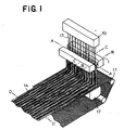
- Fig. 1 is a perspective diagram illustrating a system for making fibrous web including a perspective view of an apparatus according to this invention;
- Fig. 2 is a sectional view of the apparatus taken along line A - A in Fig. 1 partially eliminated;
- Fig. 3 is a sectional view of the apparatus taken along line B - B in Fig. 1;
- Fig. 4 is a sectional view of the apparatus taken along line c - c in Fig. 1; and
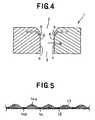
- Fig. 5 is a sectional view of the fibrous web made by the apparatus taken along line D - D in Fig. 1.
-
- Details of a cold drawing apparatus according to this invention will be more fully understood from the description given hereunder with reference to the accompanying drawings.
- Fig. 1 is a perspective diagram illustrating a system for making a
fibrous web 14 including a perspective view of acold drawing apparatus 1 according to this invention in which thefibrous web 14 and aconveyor 11 are partially eliminated. The system includes aspinning nozzle 10 adapted to discharge a plurality ofcontinuous filaments 13, acold drawing apparatus 1 adapted to cool and draw themelt spun filaments 13, anetlike collecting conveyor 11 adapted to collect thefilaments 13 thus cooled and drawn, and anair suction mechanism 12 lying below theconveyor 11 to establish an air stream sucked from an upper side toward a lower side of theconveyor 11. Thenozzle 10, theapparatus 1 and theconveyor 11 are spaced one from another by predetermined distances. Thenozzle 10 discharges a plurality offilaments 13 at a substantially constant rate and with a substantially uniform basis weight. - The
filaments 13 discharged from thenozzle 10 pass through theapparatus 1 in which thefilaments 13 are cooled and at the same time drawn before thesefilaments 13 leave theapparatus 1. Thefilaments 13 having left theapparatus 1 are collected on theconveyor 11 to formfibrous web 14 on theconveyor 11. Though not shown, thefilaments 13 are intertwined one with another by ejecting high pressure water streams to thefibrous web 14 on theconveyor 11 or by punching thefibrous web 14 with needles having barbs, or thefilaments 13 are heat-bonded one with another by subjecting thefibrous web 14 to hot blast or thefilaments 13 are bonded one to another by means of adhesive to form a desired nonwoven fabric. - Fig. 2 is a sectional view of the apparatus taken along a line A - A in Fig. 1 as partially eliminated and Figs. 3 and 4 are sectional views of the apparatus taken along lines B - B and C - C in Fig. 1, respectively. In Figs. 2, 3 and 4, illustration of the
filaments 13 is eliminated. Theapparatus 1 has aninlet 2 for thefilaments 13, anoutlet 3 for thefilaments 13,side walls 4 extending between theinlet 2 and theoutlet 3 transversely of the direction in which thefilaments 13 are discharged and opposed to each other, and an air supply opening 9 provided in the vicinity of theinlet 2 to supply compressed air toward theoutlet 3. - The
side walls 4 of theapparatus 1 definetherebetween passages 7, 8 for thefilaments 13. Theapparatus 1 cools thefilaments 13 by air stream supplied from the air supply opening 9 into thepassages 7, 8 and simultaneously stretches thefilaments 13 as thesefilaments 13 pass through thepassage 7, 8. - Each of the
side walls 4 of theapparatus 1 is formed with a plurality ofcrests 5 extending at regular intervals transversely of the direction in which thefilaments 13 are fed and a plurality oftroughs 6 extending at regular intervals also transversely of the aforesaid direction. Thecrests 5 on one of theside walls 4 are opposed to thecrests 5 on theother side wall 4 and thetroughs 6 on one of theside walls 4 are opposed to thetroughs 6 on theother side wall 4. Each of thecrests 5 is shaped in a semispherical projection having a cross-section describing a circular arc which is convex inwardly of thepassage 7. Each of thetroughs 6 extending in a fan shape between each pair of theadjacent crests 5. Thecrests 5 are round and therefore free from generation of a turbulence in the air stream flowing through thepassages 7. Accordingly, thecrests 5 are effective to prevent a stream of thefilaments 13 from being disturbed. - The minimum dimension L1 of the
passage 7 defined between each pair ofopposed crests 5 is smaller than the minimum dimension L2 of the passage 8 defined between each pair ofopposed troughs 6. An air pressure alternately rises and drops as air supplied from the supply opening 9 passes through thepassages 7 defined between the respectively opposedcrests 5 and the passages 8 defined between the respectively opposedtroughs 6. Specifically, the air pressure rises in thepassages 7 defined between the respectively opposedcrests 5 due to a pressure drag by thecrests 5 and drops in the passages 8 defined between the respectively opposedtroughs 6. A velocity of the air flow decreases in thepassages 7 defined between the respectively opposedcrests 5 in which the air pressure is relatively high and increases in the passages 8 defined between the respectively opposedtroughs 6 in which the air pressure is relatively low. - The amount of the
filaments 13 discharged from thenozzle 10 and passing through the passages 8 defined between the respectively opposedtroughs 6 is larger than the amount of thefilaments 13 passing through thepassages 7 defined between the respectively opposedcrests 5 since the velocity of air flow is higher in the passages 8 than in thepassages 7. Because of such difference in the velocity of air flow, thefilaments 13 are stretched at a higher stretch ratio as they pass through the passages 8 and thefilaments 13 are stretched at a lower stretch ratio as they pass thepassages 7. With a consequence, thefilaments 13 passing through the passages 8 have a fineness smaller than thefilaments 13 passing through thepassages 7. of thefilaments 13 collected on theconveyor 11, those having passed through the passages 8 defined between the respective opposedtroughs 6 present a density and a bulk higher than those having passed through thepassages 7 defined between the respectively opposedcrests 5. In this manner, the finishedfibrous web 14 is obtained which is formed with a pattern comprising a plurality of stripes extending longitudinally of thefibrous web 14. - In the
apparatus 1, a value corresponding to the mininun dimension L1 of thepassage 7 defined between each pair ofopposed crests 5 divided by the minimum dimension L2 of the passage defined between each pair ofopposed troughs 6 is preferably in a range of 0.1 - 0.7. The value less than 0.1 would lead to a problematic situation in which the dimension L1 of thepassage 7 defined between each pair ofopposed crests 5 is excessively smaller than the dimension L2 of the passage 8 defined between each pair ofopposed troughs 6. In this situation, thefilaments 13 would crowd in the passages 8 and thefilaments 13 passing through thepassages 7 defined between the respectively opposedcrests 5 would have a correspondingly small basis weight. As a result, regions of unacceptably low density may be generated in thefibrous web 14. The value exceeding 0.7, on the other hand, would unacceptably reduce a difference in the dimensions L1, L2 of thepassages 7, 8 and therefore correspondingly reduce a difference in the velocity of air flow in thesepassages 7, 8. consequently, the finishedfibrous web 14 as a whole would have a substantially uniform density and sometimes it would be impossible to form thefibrous web 14 with a desired pattern. - In the
apparatus 1, eachcrest 5 has its transverse dimension L3 preferably of 10 - 100 mm and eachtrough 6 has its transverse dimension L4 preferably of 10 - 100 mm. These dimensions L3, L4 less than 10 mm would, depending on a flow rate and a flow velocity of air supplied, lead to a situation in which the number of both thecrests 5 and thetroughs 6 are excessively increased and they are arranged at excessively close intervals. As a result, air streams flowing these passages would be apt to interfere one with another and to generate a turbulence in thepassages 7, 8 or a wake in the vicinity of theoutlet 3. These factors would disturb the stream of thefilaments 13 and make it impossible to form a distinct pattern on thefibrous web 14. The dimensions L3, L4 exceeding 100 mm, on the other hand, each pair ofadjacent crests 5 as well as each pair ofadjacent troughs 6 would be spaced from each other by a distance too large to form a finely striped pattern on thefibrous web 14. - If the dimension L3 of each
crest 5 is smaller than 10 mm and the dimension L4 of eachtrough 6 is larger than 100 mm, thefilaments 13 would crowd into the passages 8 defined between the respectively opposedtroughs 6 and thefilaments 13 passing through thepassages 7 defined between the respectively opposedcrests 5 would be of a correspondingly small basis weight. In a consequence, regions of excessively low density would be generated in thefibrous web 14. If the dimension L3 of eachcrest 5 exceeds 100 mm and the dimension L4 of eachtrough 6 is less than 10 mm, on the contrary, thefilaments 13 passing through thepassages 7 defined between the respectively opposedcrests 5 would have a basis weight correspondingly increased so far as the amount of thefilaments 13 discharged from thenozzle 10. The basis weight of thefilaments 13 passing through thepassages 7 would sometimes increase until a differential basis weight between thefilaments 13 passing through thepassages 7, 8 would substantially become zero and no distinct striped pattern would appear on thefibrous web 14. - It is possible without departing from the scope of this invention to oscillate the
apparatus 1 transversely thereof, i.e., in a direction indicated by a double-headed arrow X - X' in Fig. 2 so that thefibrous web 14 may be formed with a pattern comprising a plurality of stripes extending in a zigzag direction. Theapparatus 1 may be moved in any one of the directions indicated by the double-headed arrow X - X' to form a striped pattern extending obliquely to the longitudinal direction of thefibrous web 14. - Fig. 5 is a sectional view of the
fibrous web 14 taken along a line D - D in Fig. 1. Thefibrous web 14 hasregions 14a in which thefilaments 13 have relatively high density and bulk and regions 14b in which thefilaments 13 have relatively low density and bulk. Theregions 14a protrude upward with respect to the regions 14b and theseregions 14a, 14b both extending longitudinally of thefibrous web 14 define a striped pattern on thefibrous web 14. - It is possible without departing frog the scope of this invention to exploit the
cold drawing apparatus 1 in a manner that, instead of providing theair supply opening 9, an air suction mechanism is provided below theapparatus 1 and thereby an air flow is generated. A temperature of air supplied may be at a room temperature or a temperature lower than the room temperature. Each of thecrests 5 may be shaped so as to present not only the semicircular cross-section but also the other cross-sectional shape such as semi-ellipse, obelisk or triangle. - The
filaments 13 may be of thermoplastic synthetic resin such as polyolefine, polyester or polyamide. It is also possible to use elastomer made of thermoplastic synthetic resin. Such elastomer includes those made of polyolefine, polyester, polyamide and polyurethane. - The cold drawing apparatus apparatus according to this invention enables the patterned fibrous web to be made at a low cost without using an apparatus for static filamentation adapted to charge the filaments with static electricity.
- The dimensions of the passages defined between the respectively opposed crests and the passages between the respectively opposed troughs as well as the transverse dimensions of the crests and troughs may appropriately varied to obtain the fibrous web in which the filaments have a density and a bulk correspondingly varied. The fibrous web can be formed thereby optionally with a fine striped patter or a rough striped pattern.
Claims (6)
- A cold drawing apparatus interposed in a system for making a fibrous web and having an inlet for a plurality of melt spun continuous filaments, an outlet for said filaments and a pair of side walls extending between said in- and outlets and opposed to and spaced from each other in a transverse direction orthogonal to a direction in which said filaments are fed to define a passage therebetween so that said filaments are cooled and drawn as said filaments pass through said passage defined between said opposed side walls, wherein:
at least one of said opposed side walls is formed with a plurality of crests extending in said transverse direction at desired intervals and a plurality of troughs each extending between each pair of adjacent said crests. - The cold drawing apparatus according to Claim 1, wherein said crests are formed on both of said side walls at regular intervals in said transverse direction so that said crests on one of said side walls are respectively opposed to said crests on the other side walls and wherein said troughs are formed on both of said side walls at regular intervals in said transverse direction so that said troughs respectively extend in fan shapes and said troughs on one of said side walls are respectively opposed to said troughs on the other side wall.
- The cold drawing apparatus according to Claim 1, wherein a value corresponding to the minimum dimension of said passage defined between each pair of the opposed crests divided by the minimum dimension of said passage defined between each pair of the opposed troughs is in a range of 0.1 - 0.7.
- The cold drawing apparatus according to Claim 1, wherein a dimension of said crest as measured in said transverse direction is in a range of 10 - 100 mm and a dimension of said trough as measured in said transverse direction is in a range of 10 - 100 mm.
- The cold drawing apparatus according to Claim 1, wherein at least one of said side walls is formed with an air supply opening lying between said inlet and a region having said crests and troughs to supply compressed air toward said outlet.
- The cold drawing apparatus according to claim 1, wherein said apparatus is adapted to be oscillated in said transverse direction.
Applications Claiming Priority (2)
| Application Number | Priority Date | Filing Date | Title |
|---|---|---|---|
| JP20150199A JP3623402B2 (en) | 1999-07-15 | 1999-07-15 | Cooling and stretching equipment |
| JP20150199 | 1999-07-15 |
Publications (3)
| Publication Number | Publication Date |
|---|---|
| EP1069215A2 true EP1069215A2 (en) | 2001-01-17 |
| EP1069215A3 EP1069215A3 (en) | 2001-06-27 |
| EP1069215B1 EP1069215B1 (en) | 2005-01-19 |
Family
ID=16442110
Family Applications (1)
| Application Number | Title | Priority Date | Filing Date |
|---|---|---|---|
| EP00306058A Expired - Lifetime EP1069215B1 (en) | 1999-07-15 | 2000-07-17 | Cold drawing apparatus |
Country Status (12)
| Country | Link |
|---|---|
| US (1) | US6468063B1 (en) |
| EP (1) | EP1069215B1 (en) |
| JP (1) | JP3623402B2 (en) |
| KR (1) | KR100638683B1 (en) |
| CN (1) | CN1203222C (en) |
| AU (1) | AU767529B2 (en) |
| BR (1) | BR0007327A (en) |
| CA (1) | CA2313864C (en) |
| DE (1) | DE60017508T2 (en) |
| ID (1) | ID26542A (en) |
| MY (1) | MY122569A (en) |
| SG (1) | SG87134A1 (en) |
Cited By (1)
| Publication number | Priority date | Publication date | Assignee | Title |
|---|---|---|---|---|
| CN101831763A (en) * | 2010-05-27 | 2010-09-15 | 东莞市威骏不织布有限公司 | Non-woven fabric forming equipment |
Families Citing this family (6)
| Publication number | Priority date | Publication date | Assignee | Title |
|---|---|---|---|---|
| JP3658284B2 (en) * | 2000-07-05 | 2005-06-08 | ユニ・チャーム株式会社 | Nonwoven fabric manufacturing equipment |
| JP4889439B2 (en) * | 2006-10-23 | 2012-03-07 | 花王株式会社 | Elastic nonwoven fabric |
| US8246898B2 (en) * | 2007-03-19 | 2012-08-21 | Conrad John H | Method and apparatus for enhanced fiber bundle dispersion with a divergent fiber draw unit |
| CN101531455B (en) * | 2009-04-27 | 2011-06-08 | 中天科技光纤有限公司 | Optical fiber drawing cooling system |
| DE112016002637B4 (en) * | 2015-06-12 | 2022-03-24 | Reliance Industries Limited | ELECTROSTATIC MIXING DEVICE AND METHOD FOR MIXING FILAMENTS |
| WO2019187887A1 (en) * | 2018-03-29 | 2019-10-03 | 東レ株式会社 | Stretching device as well as manufacturing device and manufacturing method for fiber and fiber web |
Citations (3)
| Publication number | Priority date | Publication date | Assignee | Title |
|---|---|---|---|---|
| FR1402829A (en) * | 1962-05-16 | 1965-06-18 | Freudenberg Carl | Extrusion spinning process for fiber-based structures |
| US3554854A (en) * | 1962-02-03 | 1971-01-12 | Freudenberg Carl Kg | Non-woven fabric |
| US5853628A (en) * | 1996-09-12 | 1998-12-29 | Kimberly-Clark Worldwide, Inc. | Method of forming nonwoven fabric having a pore size gradient |
Family Cites Families (8)
| Publication number | Priority date | Publication date | Assignee | Title |
|---|---|---|---|---|
| US4064605A (en) * | 1975-08-28 | 1977-12-27 | Toyobo Co., Ltd. | Method for producing non-woven webs |
| GB2105641B (en) * | 1981-08-08 | 1985-06-26 | Bridon Int Finance | Manufacture of filamentary polymer tow |
| DE3503818C1 (en) * | 1985-02-05 | 1986-04-30 | Reifenhäuser GmbH & Co Maschinenfabrik, 5210 Troisdorf | Device for stretching monofilament bundles |
| KR930011946B1 (en) * | 1991-12-27 | 1993-12-22 | 주식회사 코오롱 | Method for preparation of the latent characteristic polyester fiber |
| DE4312419C2 (en) * | 1993-04-16 | 1996-02-22 | Reifenhaeuser Masch | Plant for the production of a spunbonded nonwoven web from aerodynamically stretched plastic filaments |
| JPH07109658A (en) | 1993-10-08 | 1995-04-25 | Toyobo Co Ltd | Nonwoven filament cloth having pattern and its production |
| DE4409940A1 (en) * | 1994-03-23 | 1995-10-12 | Hoechst Ag | Process for stretching filament bundles in the form of a thread curtain, device suitable therefor and its use for producing spunbonded nonwovens |
| GB2319745B (en) * | 1996-11-27 | 2001-01-10 | Du Pont | Spinning machine and conversion process |
-
1999
- 1999-07-15 JP JP20150199A patent/JP3623402B2/en not_active Expired - Fee Related
-
2000
- 2000-07-13 CA CA002313864A patent/CA2313864C/en not_active Expired - Fee Related
- 2000-07-14 BR BR0007327-0A patent/BR0007327A/en active Search and Examination
- 2000-07-14 MY MYPI20003230A patent/MY122569A/en unknown
- 2000-07-14 CN CNB001268147A patent/CN1203222C/en not_active Expired - Fee Related
- 2000-07-14 SG SG200003948A patent/SG87134A1/en unknown
- 2000-07-14 AU AU48624/00A patent/AU767529B2/en not_active Ceased
- 2000-07-14 KR KR1020000040534A patent/KR100638683B1/en not_active IP Right Cessation
- 2000-07-14 US US09/617,091 patent/US6468063B1/en not_active Expired - Fee Related
- 2000-07-14 ID IDP20000593D patent/ID26542A/en unknown
- 2000-07-17 EP EP00306058A patent/EP1069215B1/en not_active Expired - Lifetime
- 2000-07-17 DE DE60017508T patent/DE60017508T2/en not_active Expired - Lifetime
Patent Citations (3)
| Publication number | Priority date | Publication date | Assignee | Title |
|---|---|---|---|---|
| US3554854A (en) * | 1962-02-03 | 1971-01-12 | Freudenberg Carl Kg | Non-woven fabric |
| FR1402829A (en) * | 1962-05-16 | 1965-06-18 | Freudenberg Carl | Extrusion spinning process for fiber-based structures |
| US5853628A (en) * | 1996-09-12 | 1998-12-29 | Kimberly-Clark Worldwide, Inc. | Method of forming nonwoven fabric having a pore size gradient |
Cited By (1)
| Publication number | Priority date | Publication date | Assignee | Title |
|---|---|---|---|---|
| CN101831763A (en) * | 2010-05-27 | 2010-09-15 | 东莞市威骏不织布有限公司 | Non-woven fabric forming equipment |
Also Published As
| Publication number | Publication date |
|---|---|
| CN1282810A (en) | 2001-02-07 |
| KR100638683B1 (en) | 2006-10-27 |
| EP1069215B1 (en) | 2005-01-19 |
| KR20010049790A (en) | 2001-06-15 |
| US6468063B1 (en) | 2002-10-22 |
| CA2313864C (en) | 2003-11-25 |
| JP2001032161A (en) | 2001-02-06 |
| JP3623402B2 (en) | 2005-02-23 |
| AU767529B2 (en) | 2003-11-13 |
| EP1069215A3 (en) | 2001-06-27 |
| CA2313864A1 (en) | 2001-01-15 |
| ID26542A (en) | 2001-01-18 |
| BR0007327A (en) | 2001-12-04 |
| MY122569A (en) | 2006-04-29 |
| DE60017508T2 (en) | 2006-03-23 |
| DE60017508D1 (en) | 2005-02-24 |
| CN1203222C (en) | 2005-05-25 |
| SG87134A1 (en) | 2002-03-19 |
| AU4862400A (en) | 2001-01-18 |
Similar Documents
| Publication | Publication Date | Title |
|---|---|---|
| US3802817A (en) | Apparatus for producing non-woven fleeces | |
| CA1282921C (en) | Apparatus for making a spun-filament fleece | |
| CN1624215B (en) | Stabilized filament drawing device for a meltspinning apparatus and spun-bonded device | |
| EP2126178B1 (en) | Method and apparatus for enhanced fiber bundle dispersion with a divergent fiber draw unit | |
| JP4549541B2 (en) | Equipment for opening and distributing fiber bundles during the production of nonwoven webs | |
| CA2313864C (en) | Cold drawing apparatus | |
| CA1051840A (en) | Method and apparatus for the twin-wire air laying of fibrous pads | |
| EP1072697B1 (en) | Drawing unit | |
| IL155403A (en) | Installation for producing a spunbonded fabric web whereof the diffuser is distant from the drawing slot device | |
| US2676363A (en) | Method and apparatus for making fabrics | |
| WO2022147086A1 (en) | Meltblown system | |
| EP3428333B1 (en) | Device for manufacturing non-woven fabric and method for manufacturing non-woven fabric | |
| JPH02269859A (en) | Production of web of arranged fiber and device therefor | |
| JP2001207368A (en) | Apparatus and method for producing nonwoven fabric of filament | |
| CA2381684C (en) | Apparatus for making web comprising continuous fibers | |
| EP0094993B1 (en) | Apparatus for preparing a nonwoven web | |
| JPS6221896B2 (en) | ||
| JPH07268753A (en) | Production of web for broad nonwoven fabric | |
| JPH073604A (en) | Method for producing non-woven fabric and device therefor | |
| JPH05125648A (en) | Production of nonwoven web | |
| JPH05321116A (en) | Production of nonwoven fabric and apparatus therefor | |
| JPH09291455A (en) | Production of long-staple web | |
| JPH04163357A (en) | Production of nonwoven fabric |
Legal Events
| Date | Code | Title | Description |
|---|---|---|---|
| PUAI | Public reference made under article 153(3) epc to a published international application that has entered the european phase |
Free format text: ORIGINAL CODE: 0009012 |
|
| AK | Designated contracting states |
Kind code of ref document: A2 Designated state(s): DE FR GB IT NL SE |
|
| AX | Request for extension of the european patent |
Free format text: AL;LT;LV;MK;RO;SI |
|
| PUAL | Search report despatched |
Free format text: ORIGINAL CODE: 0009013 |
|
| AK | Designated contracting states |
Kind code of ref document: A3 Designated state(s): AT BE CH CY DE DK ES FI FR GB GR IE IT LI LU MC NL PT SE |
|
| AX | Request for extension of the european patent |
Free format text: AL;LT;LV;MK;RO;SI |
|
| 17P | Request for examination filed |
Effective date: 20011119 |
|
| AKX | Designation fees paid |
Free format text: DE FR GB IT NL SE |
|
| 17Q | First examination report despatched |
Effective date: 20040223 |
|
| RAP1 | Party data changed (applicant data changed or rights of an application transferred) |
Owner name: UNI-CHARM CORPORATION |
|
| GRAP | Despatch of communication of intention to grant a patent |
Free format text: ORIGINAL CODE: EPIDOSNIGR1 |
|
| GRAS | Grant fee paid |
Free format text: ORIGINAL CODE: EPIDOSNIGR3 |
|
| GRAA | (expected) grant |
Free format text: ORIGINAL CODE: 0009210 |
|
| AK | Designated contracting states |
Kind code of ref document: B1 Designated state(s): DE FR GB IT NL SE |
|
| REG | Reference to a national code |
Ref country code: GB Ref legal event code: FG4D |
|
| REF | Corresponds to: |
Ref document number: 60017508 Country of ref document: DE Date of ref document: 20050224 Kind code of ref document: P |
|
| REG | Reference to a national code |
Ref country code: SE Ref legal event code: TRGR |
|
| PLBE | No opposition filed within time limit |
Free format text: ORIGINAL CODE: 0009261 |
|
| STAA | Information on the status of an ep patent application or granted ep patent |
Free format text: STATUS: NO OPPOSITION FILED WITHIN TIME LIMIT |
|
| ET | Fr: translation filed | ||
| 26N | No opposition filed |
Effective date: 20051020 |
|
| PGFP | Annual fee paid to national office [announced via postgrant information from national office to epo] |
Ref country code: IT Payment date: 20060731 Year of fee payment: 7 |
|
| PG25 | Lapsed in a contracting state [announced via postgrant information from national office to epo] |
Ref country code: IT Free format text: LAPSE BECAUSE OF NON-PAYMENT OF DUE FEES Effective date: 20070717 |
|
| REG | Reference to a national code |
Ref country code: FR Ref legal event code: PLFP Year of fee payment: 17 |
|
| PGFP | Annual fee paid to national office [announced via postgrant information from national office to epo] |
Ref country code: FR Payment date: 20160613 Year of fee payment: 17 Ref country code: NL Payment date: 20160610 Year of fee payment: 17 |
|
| PGFP | Annual fee paid to national office [announced via postgrant information from national office to epo] |
Ref country code: GB Payment date: 20160713 Year of fee payment: 17 Ref country code: DE Payment date: 20160712 Year of fee payment: 17 |
|
| PGFP | Annual fee paid to national office [announced via postgrant information from national office to epo] |
Ref country code: SE Payment date: 20160712 Year of fee payment: 17 |
|
| REG | Reference to a national code |
Ref country code: DE Ref legal event code: R119 Ref document number: 60017508 Country of ref document: DE |
|
| REG | Reference to a national code |
Ref country code: NL Ref legal event code: MM Effective date: 20170801 |
|
| REG | Reference to a national code |
Ref country code: SE Ref legal event code: EUG |
|
| GBPC | Gb: european patent ceased through non-payment of renewal fee |
Effective date: 20170717 |
|
| REG | Reference to a national code |
Ref country code: FR Ref legal event code: ST Effective date: 20180330 |
|
| PG25 | Lapsed in a contracting state [announced via postgrant information from national office to epo] |
Ref country code: NL Free format text: LAPSE BECAUSE OF NON-PAYMENT OF DUE FEES Effective date: 20170801 Ref country code: SE Free format text: LAPSE BECAUSE OF NON-PAYMENT OF DUE FEES Effective date: 20170718 Ref country code: DE Free format text: LAPSE BECAUSE OF NON-PAYMENT OF DUE FEES Effective date: 20180201 Ref country code: GB Free format text: LAPSE BECAUSE OF NON-PAYMENT OF DUE FEES Effective date: 20170717 |
|
| PG25 | Lapsed in a contracting state [announced via postgrant information from national office to epo] |
Ref country code: FR Free format text: LAPSE BECAUSE OF NON-PAYMENT OF DUE FEES Effective date: 20170731 |