EP1067863B1 - Three-axis coil sensor - Google Patents
Three-axis coil sensor Download PDFInfo
- Publication number
- EP1067863B1 EP1067863B1 EP99914039A EP99914039A EP1067863B1 EP 1067863 B1 EP1067863 B1 EP 1067863B1 EP 99914039 A EP99914039 A EP 99914039A EP 99914039 A EP99914039 A EP 99914039A EP 1067863 B1 EP1067863 B1 EP 1067863B1
- Authority
- EP
- European Patent Office
- Prior art keywords
- transducers
- probe
- field
- patient
- reference field
- Prior art date
- Legal status (The legal status is an assumption and is not a legal conclusion. Google has not performed a legal analysis and makes no representation as to the accuracy of the status listed.)
- Expired - Lifetime
Links
- 239000000523 sample Substances 0.000 claims description 138
- 230000000712 assembly Effects 0.000 claims description 48
- 238000000429 assembly Methods 0.000 claims description 48
- 238000000034 method Methods 0.000 claims description 27
- 230000005291 magnetic effect Effects 0.000 claims description 18
- 239000000758 substrate Substances 0.000 claims description 16
- 230000005540 biological transmission Effects 0.000 claims description 6
- 238000004364 calculation method Methods 0.000 claims description 6
- 238000010438 heat treatment Methods 0.000 claims description 2
- 230000002093 peripheral effect Effects 0.000 claims 2
- 238000003384 imaging method Methods 0.000 description 9
- 239000010410 layer Substances 0.000 description 8
- 239000000463 material Substances 0.000 description 8
- 230000008901 benefit Effects 0.000 description 6
- 230000003287 optical effect Effects 0.000 description 6
- 239000000853 adhesive Substances 0.000 description 5
- 230000001070 adhesive effect Effects 0.000 description 5
- 238000005259 measurement Methods 0.000 description 5
- 210000000038 chest Anatomy 0.000 description 4
- 239000003550 marker Substances 0.000 description 4
- 230000005672 electromagnetic field Effects 0.000 description 3
- 230000005865 ionizing radiation Effects 0.000 description 3
- 230000003902 lesion Effects 0.000 description 3
- 229910052751 metal Inorganic materials 0.000 description 3
- 239000002184 metal Substances 0.000 description 3
- 230000035945 sensitivity Effects 0.000 description 3
- 230000005355 Hall effect Effects 0.000 description 2
- 230000000747 cardiac effect Effects 0.000 description 2
- 239000004020 conductor Substances 0.000 description 2
- 238000001816 cooling Methods 0.000 description 2
- 230000005294 ferromagnetic effect Effects 0.000 description 2
- 239000003302 ferromagnetic material Substances 0.000 description 2
- 238000002595 magnetic resonance imaging Methods 0.000 description 2
- 230000007246 mechanism Effects 0.000 description 2
- 150000002739 metals Chemical class 0.000 description 2
- 238000012544 monitoring process Methods 0.000 description 2
- 229920000642 polymer Polymers 0.000 description 2
- 210000001519 tissue Anatomy 0.000 description 2
- 244000261422 Lysimachia clethroides Species 0.000 description 1
- 239000004642 Polyimide Substances 0.000 description 1
- 210000001015 abdomen Anatomy 0.000 description 1
- 239000012790 adhesive layer Substances 0.000 description 1
- 239000002390 adhesive tape Substances 0.000 description 1
- 229910052782 aluminium Inorganic materials 0.000 description 1
- XAGFODPZIPBFFR-UHFFFAOYSA-N aluminium Chemical compound [Al] XAGFODPZIPBFFR-UHFFFAOYSA-N 0.000 description 1
- 210000003484 anatomy Anatomy 0.000 description 1
- 238000013459 approach Methods 0.000 description 1
- 238000001574 biopsy Methods 0.000 description 1
- 230000036760 body temperature Effects 0.000 description 1
- 210000000988 bone and bone Anatomy 0.000 description 1
- 210000004556 brain Anatomy 0.000 description 1
- 239000011248 coating agent Substances 0.000 description 1
- 238000000576 coating method Methods 0.000 description 1
- 238000007796 conventional method Methods 0.000 description 1
- 239000002826 coolant Substances 0.000 description 1
- 238000007428 craniotomy Methods 0.000 description 1
- 238000001514 detection method Methods 0.000 description 1
- 238000003745 diagnosis Methods 0.000 description 1
- 230000000694 effects Effects 0.000 description 1
- 230000005670 electromagnetic radiation Effects 0.000 description 1
- 238000002594 fluoroscopy Methods 0.000 description 1
- 230000004927 fusion Effects 0.000 description 1
- 238000009413 insulation Methods 0.000 description 1
- 238000012804 iterative process Methods 0.000 description 1
- 238000010030 laminating Methods 0.000 description 1
- 238000012830 laparoscopic surgical procedure Methods 0.000 description 1
- 238000013507 mapping Methods 0.000 description 1
- 230000000737 periodic effect Effects 0.000 description 1
- 229920001721 polyimide Polymers 0.000 description 1
- 230000002035 prolonged effect Effects 0.000 description 1
- 230000001737 promoting effect Effects 0.000 description 1
- 230000003252 repetitive effect Effects 0.000 description 1
- 230000000241 respiratory effect Effects 0.000 description 1
- 230000002441 reversible effect Effects 0.000 description 1
- 238000005070 sampling Methods 0.000 description 1
- 210000004872 soft tissue Anatomy 0.000 description 1
- 239000007787 solid Substances 0.000 description 1
- 238000012546 transfer Methods 0.000 description 1
- 230000017105 transposition Effects 0.000 description 1
- 238000002604 ultrasonography Methods 0.000 description 1
- XLYOFNOQVPJJNP-UHFFFAOYSA-N water Substances O XLYOFNOQVPJJNP-UHFFFAOYSA-N 0.000 description 1
- 238000004804 winding Methods 0.000 description 1
Images


Classifications
-
- H—ELECTRICITY
- H01—ELECTRIC ELEMENTS
- H01F—MAGNETS; INDUCTANCES; TRANSFORMERS; SELECTION OF MATERIALS FOR THEIR MAGNETIC PROPERTIES
- H01F5/00—Coils
-
- A—HUMAN NECESSITIES
- A61—MEDICAL OR VETERINARY SCIENCE; HYGIENE
- A61B—DIAGNOSIS; SURGERY; IDENTIFICATION
- A61B34/00—Computer-aided surgery; Manipulators or robots specially adapted for use in surgery
- A61B34/20—Surgical navigation systems; Devices for tracking or guiding surgical instruments, e.g. for frameless stereotaxis
-
- A—HUMAN NECESSITIES
- A61—MEDICAL OR VETERINARY SCIENCE; HYGIENE
- A61B—DIAGNOSIS; SURGERY; IDENTIFICATION
- A61B5/00—Measuring for diagnostic purposes; Identification of persons
- A61B5/06—Devices, other than using radiation, for detecting or locating foreign bodies ; determining position of probes within or on the body of the patient
- A61B5/061—Determining position of a probe within the body employing means separate from the probe, e.g. sensing internal probe position employing impedance electrodes on the surface of the body
- A61B5/062—Determining position of a probe within the body employing means separate from the probe, e.g. sensing internal probe position employing impedance electrodes on the surface of the body using magnetic field
-
- A—HUMAN NECESSITIES
- A61—MEDICAL OR VETERINARY SCIENCE; HYGIENE
- A61B—DIAGNOSIS; SURGERY; IDENTIFICATION
- A61B17/00—Surgical instruments, devices or methods, e.g. tourniquets
- A61B17/28—Surgical forceps
- A61B17/29—Forceps for use in minimally invasive surgery
- A61B2017/2901—Details of shaft
- A61B2017/2905—Details of shaft flexible
-
- A—HUMAN NECESSITIES
- A61—MEDICAL OR VETERINARY SCIENCE; HYGIENE
- A61B—DIAGNOSIS; SURGERY; IDENTIFICATION
- A61B34/00—Computer-aided surgery; Manipulators or robots specially adapted for use in surgery
- A61B34/20—Surgical navigation systems; Devices for tracking or guiding surgical instruments, e.g. for frameless stereotaxis
- A61B2034/2046—Tracking techniques
- A61B2034/2051—Electromagnetic tracking systems
-
- A—HUMAN NECESSITIES
- A61—MEDICAL OR VETERINARY SCIENCE; HYGIENE
- A61B—DIAGNOSIS; SURGERY; IDENTIFICATION
- A61B34/00—Computer-aided surgery; Manipulators or robots specially adapted for use in surgery
- A61B34/20—Surgical navigation systems; Devices for tracking or guiding surgical instruments, e.g. for frameless stereotaxis
- A61B2034/2072—Reference field transducer attached to an instrument or patient
-
- A—HUMAN NECESSITIES
- A61—MEDICAL OR VETERINARY SCIENCE; HYGIENE
- A61B—DIAGNOSIS; SURGERY; IDENTIFICATION
- A61B90/00—Instruments, implements or accessories specially adapted for surgery or diagnosis and not covered by any of the groups A61B1/00 - A61B50/00, e.g. for luxation treatment or for protecting wound edges
- A61B90/39—Markers, e.g. radio-opaque or breast lesions markers
- A61B2090/3983—Reference marker arrangements for use with image guided surgery
Definitions
- the present invention relates to systems for medical diagnosis and treatment, and specifically to using reference field transducers and medical probes with probe field transducers to detect the position, orientation, or both within the body of a patient.
- probes such as catheters
- cardiac catheterization and neurosurgery it is often necessary for the physician or surgeon to know the location of the distal end of the probe inside the body.
- imaging methods such as fluoroscopy and ultrasound are sometimes used for this purpose, they are not always practical or desirable.
- fluoroscopic systems are often undesirable because that they expose the patient and physician to substantial ionizing radiation.
- Systems such as those disclosed in the '091, '199, and '489 patents and in the '938 PCT application determine the disposition (i.e., position, orientation, or both) of a probe using one or more field transducers, such as a Hall effect devices, magnetoresistive devices, coils or other antennas carried on the probe.
- the transducers are typically located at or adjacent the distal end of the probe or at a precisely known location relative to the distal end of the probe.
- Such systems further utilize one or more reference field transducers disposed outside the body to provide an external frame of reference.
- the reference field transducers are operative to transmit or detect non-ionizing fields or field components such as magnetic field, electromagnetic radiation or acoustical energy such as ultrasonic vibration.
- the frame of reference of the external field transducers can be registered with the frame of reference of imaging data such as magnetic resonance imaging data, computerized axial tomographic ("CAT") data, or conventional x-ray imaging data, and hence the position and/or orientation data derived from the system can be displayed as a representation of the probe superimposed on an image of the patient's body.
- the physician can use this information to guide the probe to the desired location within the patient's body, and to monitor its location and orientation during treatment or measurement of the internal body structure.
- This arrangement greatly enhances the ability of the physician to navigate the distal end of the probe through bodily structures and offers significant advantages over conventional methods of navigating probes within the body by feel alone.
- transducer-based systems Because it does not require acquiring an optical image of the surrounding tissues for navigation purposes, it can be used with probes which are too small to accommodate optical elements. These transducer-based systems also avoid the difficulties associated with navigation of a probe by continuous imaging of the probe and patient during the procedure and avoids, for example, prolonged exposure to ionizing radiation inherent in fluoroscopic systems.
- Such systems typically utilize reference field transducers or coils which are provided in a fixed, immovable array, in locations such as on the ceiling of an operating room or rigidly fixed to operating or catheterization table.
- the coil mounting may interfere with free access by the physician to the patient.
- the aforementioned '938 publication describes a catheter system which uses a plurality of non-concentric coils adjacent to the distal end of the catheter. These coils generate signals in response to externally applied magnetic fields, which allow for the computation of six location and orientation coordinates, so that the disposition of the catheter is known without the need for simultaneous imaging.
- at least three such coils or radiators are arrayed in fixed locations outside the body, adjacent to the area of the body into which the catheter is introduced.
- three radiators are typically fixedly placed beneath the patient's thorax, in a fixed coplanar, triangular arrangement, with the centers of the coils from about 2 to 40 cm apart.
- the transducers or field radiating coils should desirably be positioned adjacent to the patient's head.
- the patient if often in a seated, upright position or else face-down.
- a triangular frame holding the three radiators as described above cannot be comfortably and stably positioned below the head.
- positioning the frame above or beside the head will generally interfere with the surgeon's manipulation of probes and surgical tools.
- WO97/29685 discloses an apparatus according to the preamble of claim 1.
- a system in accordance with this aspect of the invention desirably includes a probe having one or more probe field transducers mounted thereon.
- One or more reference field transducers as claimed in claim 1 are also provided.
- the term "field transducer" encompasses a device which can transmit a non-ionizing field such as a magnetic, electromagnetic, acoustic or optical field and also encompasses a device which can detect one or more components of such a field.
- the reference field transducers are independently movable with respect to one another and are locatable by the user in desired, user-selected, customizable positions with respect to the body of the patient.
- the system includes means for mounting the reference field transducers on the body of the patient.
- the reference field transducers are mechanically unattached to one another, so that each reference field transducer can be placed in any disposition desired by the user without mechanical constraints imposed by placement of the other reference field transducers.
- Calibration means are provided for determining the relative dispositions of the field transducers with respect to one another while the reference field transducers are located in the desired positions as, for example, while the reference field transducers are mounted on the patient's body.
- disposition refers to the position of the object, the orientation of the object, or both.
- relative disposition refers to the direction from one object to the other, the distance from one object to the other, or both, and also includes the orientation of each object in the frame of reference of the other object.
- the calibration means is arranged to fully determine all parameters of the relative disposition of the field transducers with respect to one another, so that the distances and directions from each field transducer to each other field transducer, and the orientations of all of the field transducers, are fully known.
- the system further includes transmission means to actuate the reference field transducers and probe field transducers so as to transmit one or more non-ionizing fields between the reference field transducers and the probe field transducer or transducers an detect each such transmitted field.
- transmission means to actuate the reference field transducers and probe field transducers so as to transmit one or more non-ionizing fields between the reference field transducers and the probe field transducer or transducers an detect each such transmitted field.
- the transmission means actuate the reference field transducers to transmit a magnetic or electromagnetic field
- the probe field transducer detects properties of the field received at the probe field transducer or transducers.
- Calculation means are also provided to determine the disposition of the probe in the frame of reference of the reference field transducers. This calculation proceeds from properties of the detected fields and from the relative dispositions of the reference field transducers with respect to one another.
- the reference field transducers are independently positionable on or near the patient, they can be placed in an optimum arrangement to provide good sensitivity and signal to noise ratio in the particular area of interest, where a probe must be located during a particular procedure. Also, location of the reference field transducers can be selected to provide unimpeded access for surgical or other medical procedures. As further explained below, the frame of reference defined by the reference field transducers can be registered with the frame of reference of a previously acquired image, and a representation of the probe can be displayed superposed on the previously acquired image. In preferred embodiments where the reference field transducers are mounted on the patient's body, the frame of reference defined by the reference field transducers moves with the patient.
- the calibration means and calculation means are arranged to redetermine the relative dispositions of the reference field transducers periodically and to redetermine the disposition of the probe based upon the redetermined relative dispositions of the reference field transducers.
- the system may operate cyclically, so that each cycle includes redetermination of the relative dispositions of the reference field transducers as well as determination of the probe disposition.
- the frame of reference of the reference field transducers is updated before each measurement of probe disposition.
- the reference field transducer disposition may be updated periodically.
- the calibration means may include one or more calibration field transducers mounted to one or more of the reference field transducers.
- one or more of the reference field transducers is provided in a reference assembly with one or more calibration field transducers.
- the calibration means is arranged to determine the relative dispositions of the reference field transducers by detecting non-ionizing fields transmitted to or from the calibration field transducers as, for example, field transmitted from the reference transducers of other reference assemblies.
- Methods according to this aspect of the invention desirably include the steps of providing a probe as aforesaid having one or more probe field transducers and positioning a plurality of reference field transducers as claimed in claim 1 positionable independently with respect to one another in desired, user-selected customizable positions with respect to the body of the patient.
- the relative dispositions of the reference field transducers with respect to one another are determined while the reference field transducers are located in their desired positions.
- the probe is then located by transmitting one or more non-ionizing fields between the probe field transducers and reference field transducers and detecting these fields.
- the relative disposition of the probe with respect to the reference field transducers is determined from the properties of the detected fields and from the relative dispositions of the reference field transducers with respect to one another. As discussed above in connection with the apparatus, the relative dispositions of the reference field transducers desirably are redetermined frequently.
- Still further aspects of the present invention include apparatus for generating or detecting non-ionizing fields transmitted to or from within the body of a patient.
- aspects according to this aspect of the invention includes a plurality of reference field transducers according to claim 1 and means for positioning each of the reference field transducers independently with respect to one another in desired, customizable positions in close proximity to the body of a medical patient.
- Apparatus according to this aspect of the present invention can be utilized in the systems and methods discussed above.
- the positioning means may incorporate means for securing each reference field transducer to the body of the patient as, for example, adhesive means or other fastening devices which can engage the body.
- a still further aspect of the present invention includes a kit incorporating a plurality of separate reference field transducers and means such as adhesives or other fastening devices for securing the reference field transducers to the body of the patient.
- a still further aspect of the present invention includes a reference field transducer assembly which incorporates a coil or other field transducer that generates heat during operation and a housing structure containing such coil. The assembly has a front surface which lies against the patient during operation and a rear surface. Means are provided in the housing for limiting heating of the front surface by heat generated in the coil.
- the housing may include thermal insulation disposed between the coil and the front surface and preferably also includes means for dissipating heat within the housing or through the rear surface.
- the present invention relates to magnetic field sensors used to detect the position and orientation of medical probes within the body of a patient.
- the sensors of the present invention are especially adapted for use as independently positionable reference transducer assemblies as claimed in claim 1.
- Such assemblies are, for example, those described in commonly-owned, co-pending International Application No. PCT/US97/02650 entitled “Independently Positionable Transducers for Location System” ("the '650 application”).
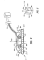
- a system in accordance with one embodiment of the invention is used in conjunction with an elongated probe in the form of a tube or catheter 20 having a proximal end 22 and a distal end 24.
- a probe body 28 incorporating a probe field transducer or position sensor 30 is physically connected to the distal end 24 of catheter 20.
- Probe field transducer 30 is preferably provided in the form of a sensor arranged to detect magnetic or electromagnetic fields.
- the probe field transducer 30 may be a multi-axis, solid-state position sensor of the type disclosed in the aforementioned U.S. Patent 5,558,091.
- Such a sensor incorporates a plurality of transducers sensitive to magnetic field components in mutually orthogonal directions.
- Suitable position sensors include coils as disclosed in the aforementioned U.S. Patent 5,391,199 and in International Publication WO 96/05768. Such coils may be provided as a single coil or as a plurality of orthogonal coils capable of detecting field components in orthogonal directions.
- Elongated probe or tube 20 is constructed and arranged to be navigable within the body of the patient to a desired location.
- tube 20 may have the structure of a conventional catheter, endoscope, laparoscope or the like.
- the size and shape of tube 20 will also depend upon the region of the body to be treated.
- the probe may incorporate essentially any device which can be inserted or advanced into the body to perform a medical procedure, such as for treatment, measurement or observation, and capturing tissue samples or other materials within the body.
- Tube 20 may also be constructed to accommodate a conventional intrabody medical instrument such a scissors or forceps, or other surgical tools operable from the proximal end or handle of the device.
- Such a surgical tool may be any conventional surgical tool of the type commonly used in endoscopic, arthroscopic or laparoscopic surgical procedures, or a conventional biopsy sampling device.
- a surgical tool may be any conventional surgical tool of the type commonly used in endoscopic, arthroscopic or laparoscopic surgical procedures, or a conventional biopsy sampling device.
- probe any instrument or device which can be inserted into the body may function as a probe, and hence the term "probe" should not be taken as limited to any specific configuration.
- each reference transducer assembly 50 includes a cylindrical coil 100 fabricated from fine gauge wire. Such a coil preferably includes approximately 2000 turns of wire to form a coil with a diameter of 76.2 or 101.6 mm (3 or 4 inches) of less, and a height of 6.4 mm (1 ⁇ 4 inch) or less. Coils such as these are currently sold as heater coils by Minco of Minneapolis, Minnesota. Each cylindrical coil is formed on a cylindrical bobbin 300 and defines a coil axis 302 concentric with the coil.
- Each reference assembly 50 further includes a housing incorporating a front panel 304 and a rear panel 306.
- Front panel 304 is provided with a cushioning layer 308 which in turn has an adhesive coating on its exposed front surface 310.
- Front panel 304 and hence its exposed, adhesive coated front surface 310 extend generally transverse to the coil axis 302.
- a layer of a peelable release film 311 may be removably positioned over surface 310. Layer 311 protects the adhesive on surface 310 during shipment and handling, but is removed during use of the assembly.
- the reference assembly can be provided with features such as elastic bands, straps, clamps or other devices for securing it to the body of a patient.
- the housing elements 304 and 306 can be provided with features such as holes or tie points for cooperation with user-supplied fastening devices such a sutures for holding the assembly in place.
- the fastening features can be provided directly on the reference field transducer or coil 100, as on bobbin 300, and the housing elements can be omitted.
- Rear surface 306 is provided with vents 312 to permit dissipation of heat generated during operation of coil 100.
- the rear panel can be equipped with fins, and can be fabricated from a highly heat conductive nonmagnetic material such as aluminum.
- the region within the housing surrounding coil 100 can be filled with a material having a high specific heat or with a fusable material adapted to melt and take up heat in latent heat of fusion, preferably at a temperature slightly above normal body temperature such as about 40-50°C.
- a plurality of calibration transducer sockets 314 are formed integrally with the housing at fixed positions relative to coil 100.
- each transducer assembly 50 has three sockets 314 disposed around the periphery of coil 100.
- the sockets are disposed desirably at spaced locations around the coil axis 302 and thus form vertices of a triangle in a plane perpendicular to coil axis 302.
- Each socket 304 is adapted to receive a calibration field transducer 316 and to hold the calibration field transducer in a predetermined position and orientation relative to the coil 100 of the same reference assembly 50.
- each calibration field transducer 316 desirably includes a set of three orthogonal transducer elements 318, 320 and 322 adapted to detect magnetic field components in three mutually orthogonal directions.
- the active transducer elements may be solid state transducers such as Hall-effect or magnetoresistive transducers. Alternatively, the active elements may be coils wound on mutually intersecting axes.
- the active elements 318, 320 and 322 are housed in an outer package or housing 324.
- Each socket 314 and/or the housings 324 of the calibration field transducers 316 and the sockets 314 may include conventional features such as snaps, pins, clasps and other features for mechanical fastening.
- the housing 324 of the calibration transducers may be adapted to fit closely within sockets 314, so that each housing is held in an accurate, repeatable position with respect to coil 100.
- the housings 324 of the calibration transducers 316 can be formed integrally with the coil housing elements 304 and 306, may be formed integrally with the coil bobbin 300 or may be otherwise attached permanently to the coil bobbin or housing.
- the reference field transducers or coils 100, and the calibration field transducers 316 of the various reference assemblies 50 are connected through leads 51 to a field transmitting and receiving device 80.
- reference assemblies 50 are removably detachable from leads 51 to allow easy replacement and/or disposal after use.
- Providing disposable reference assemblies is advantageous since resterilization of the transducers, which may cause damage to the sensitive transducers, can be eliminated.
- providing detachable transducers allows further customization by allowing interchangeability among different sized reference assemblies for different medical procedures and patient sizes.
- the various transducers on each reference assembly can be connected to the transmitting and receiving device 80 through wireless telemetry, as by RF or infrared telemetry.
- each reference assembly 50 may include a self-contained power supply such as a battery.
- Field transmitting and receiving device 80 is connected to a computer 85, which can consist of a microcomputer, work station, mainframe or other similar computing device, which in turn is connected to a display device, such as cathode ray tube (CRT) monitor 95.
- Field transmitting and receiving device 80 and computer 85 are arranged to cooperate with the probe field transducers 30 and coils reference field transducers 100 to transmit and receive non-ionizing fields, preferably electromagnetic fields, to determine the disposition of the probe 28 in the frame of reference of the reference field transducers 100.
- reference assemblies 50 are mounted to the patient at arbitrary, user selected dispositions by adhering the front surfaces 310 to the patient.
- the dispositions of the reference assemblies 50, and hence the dispositions of the reference field transducers 100 can be selected as desired by the physician or other person mounting the reference assemblies.
- the reference assemblies are mounted so as to place the various coils or reference transducers 100 in proximity to a region of interest within the patient, i.e., in proximity to a region where the distal tip of probe 28 is to be employed.
- the particular dispositions illustrated in Figs. 1 and 4 are intended merely for purposes of illustration and should not be taken as limiting the positions in which the reference field transducers can be placed.
- the reference assemblies can be placed in a generally coplanar arrangement on the patient's back, with the coil axes 302 extending generally parallel to one another so that the coil axes surround the center of the region of interest.
- the various field transducers can be placed in a generally U-shaped arrangement, as depicted in Fig. 4, so that the axes 302 of the reference transducers or coils 100 in all of the reference assemblies converge in the region of interest.
- the reference field transducers 100 When positioned on the patient, the reference field transducers 100 define an external frame of reference. Electromagnetic or magnetic fields can be transmitted between reference field transducers 100 and the transducer 30 on the probe, such that the disposition of the probe field transducer and probe 28 can be calculated from the characteristics of the fields, such as strength and direction, as detected by the probe field transducer.
- the reference field transducers 100 and the probe field transducer 30 cooperatively define a plurality of transmitter-receiver pairs. Each such pair includes one transmitter and one receiver as elements of the pair. One element of each such pair is disposed on the probe and the other element of each such pair is disposed in the frame of reference defined by the reference field transducers 100.
- each transmitter-receiver pair is disposed at a different position or orientation than the corresponding element of the other pairs.
- the system can deduce information relating to the disposition of the probe in the external frame of reference defined by the reference field transducers.
- the disposition information can include the position of the probe, the orientation of the probe, or both.
- the calculation relies upon the reference field transducers being positioned in known positions and orientations relative to one another.
- Calibration field transducers 316 cooperate with reference field transducers or coils 100 to provide the information necessary to calculate the position and orientation of the reference assemblies relative to one another.
- the coil 100 of each reference assembly 50 constitutes a single axis field transducer
- the calibration field transducers 316 of each reference assembly 50 represent a system of three three-axis transducers disposed at known locations with respect to one another.
- the three calibration transducers 316B, 316B2, and 316B3 of reference assembly 50B are at known locations relative to one another.
- the algorithm proceeds by treating the reference field transducer coil 100A as if it were a uniform radiator, and ignoring the effect of orientation of coil 100A on the field component magnitudes determined at calibration transducers 316B. Stated another way, in this initial stage coil 100A is treated as it is radiated a spherical field. Using this assumption, and the field component magnitudes detected calibration transducers 316B, the system arrives at an initial estimate of the position of coil 100A relative to reference assembly 50B.
- the system uses that initial estimate of position and the detected field component magnitudes at calibration transducers 316B to calculate orientation angles for coil 100A. Using the newly-calculated orientation angles, the system calculates a better estimate of position. The last two steps are repeated until new estimate of position matches the last previous estimate of position within a preselected tolerance. Stated another way, the system converges to the correct position and orientation angles. Further details of the algorithm are given in the '938 Publication. The same algorithm can be used to find the location of coil 100C with respect to reference assembly 50C.
- the position and orientation of coil 100B with respect to assembly 50C can be determined by monitoring signals from the three, three-axis calibration field transducers 316 on reference assembly 50C.
- the location of coil 100B with respect to reference assembly 50A can be determined from the signals generated by calibration field transducers 316A on reference assembly 50A while coil 100B is active.
- the disposition of coil 100C with respect to assemblies 50A and 50B can be determined.
- the system provides redundant information, including two independently determined sets of position and orientation parameters defining the relative dispositions of each pair of reference assemblies. This redundant information can be used in checking the values obtained and in arriving at an estimate for the true values which minimized the total error in the system.
- an estimate of the error for that pair can be obtained. Similar estimates can be obtained for the error in relative dispositions of other pairs of reference assemblies.
- the computer can select estimates of the true dispositions of the various reference assemblies which yield the lowest total error.
- the two estimates of relative disposition for each pair of reference assemblies can simply be averaged with one another.
- the system can be modified to use fewer calibration transducers and thereby eliminate some of the redundant information.
- the system can be modified to use fewer calibration transducers and thereby eliminate some of the redundant information.
- the reference field transducers comprise single-axis field transmission coils
- a system using only three, three-dimensional field receiving calibration transducers on only one reference assembly will allow determination of the relative positions and orientations of the three transmitting coils with respect to one another.
- the reference field transducers can function as calibration transducers. For example, if coil 100A is energized with an alternating current, the alternating field can be detected by reference field transducers 100B and 100C of the other reference assemblies. Those signals provide additional information which can be used in the calibration process.
- a fixed array of calibration field transducers is provided, such as calibration array 55 (Fig. 1) which includes a plurality of calibration field transducers 56 attached to field transmitting and receiving device 80 through leads 57. Because the transducers 56 of the calibration array are provided in fixed, known relationship with respect to one another, the individual positions of each of the reference field transducers with respect to the array transducers can be determined in accordance with the algorithms disclosed, for example, in the aforementioned '938 International Publication. Once the positions of reference field transducers 100 in the frame of reference of calibration array 55 have been determined, the dispositions of the reference field transducers relative to one another can be calculated directly. In this arrangement, the calibration field transducers can be omitted from the reference assemblies 50.
- the disposition of the probe in the external reference frame defined by the reference field transducers can be determined as set forth for instance in the '091 patent, by transmitting and receiving non-ionizing fields between the reference field transducers and the probe field transducers.
- the patient is positioned on the patient bed 60 and the reference assemblies 50 are independently positioned in desired arrangements on or near the patient.
- the external frame of reference is determined by use of the calibration and reference field transducer pairs. Namely, the field transmitting and receiving unit 80 and computer 85 actuate the reference field transducers or the calibration field transducers to transmit and receive fields as discussed above. Using the above described method, the computer 85 calculates the disposition of the reference field transducers 100 with respect to one another to determine the external reference frame.
- the distal end of the probe 28 is advanced into the patient towards the area of interest, carrying the probe field transducer 30.
- the field transmitting and receiving unit 80 and computer 85 then actuate the external field transducers 100 and probe field transducer 30 to transmit and receive fields.
- the probe field transducers 100 are field transmitters
- the probe field transducers will send signals representing the fields detected at the probe to the field transmit and receive unit.
- drive signals are sent to the probe field transducers.
- the computer 85 then deduces the disposition of the probe field transducer 30 and thus deduces the disposition of the probe itself in the external frame of reference defined by the reference field transducers 100.
- the step of finding the disposition of the probe field transducer 30 can be performed by known techniques such as those taught in the '091 Patent and in the '938 Publication.
- probe 28 and hence field transducer 30 are brought to several prominent points on the patient which are readily identifiable in the image as, for example, readily identifiable bone structures depicted in the image data.
- fiducial markers 71 can be fastened in place on the patient's body before the image is acquired, so that the fiducial markers are depicted in the image and are accessible to the probe.
- the data defining each prominent point or marker is supplied to the computer, as by positioning a cursor over the depiction of the point on display screen 95.
- the physician brings probe 28 into engagement with each prominent points or fiducial markers, he supplies a manual input to the computer, whereupon the computer records the current position of probe 28 in the reference frame of the field transducers 100 as the position of the prominent point or marker in that reference frame.
- Data defining the position of each such point or marker in the image frame of reference is combined with data of defining the same points in the frame of reference of field transducers 100 to arrive at a transposition vector relating the two frames of reference to one another.
- the contour of a rigid element in the patient's body as, for example, the patient's face can be traced with the probe tip and matched to the same contour in the image frame of reference.
- one or more registration marker field transducers 70 may be provided on fiducial markers which are attached to the patient prior to imaging. The system tracks disposition of the registration field transducers in the frame of reference of field transducers 100 in the same manner as it tracks disposition of the probe transducer 30, so that positions of the fiducial markers in the field transducer reference frame are known.
- the transducers define a reference frame that is fixed with respect to with the patient.
- the reference field transducers are mounted to rigid portions of the patient's body (such as on the head)
- the requirement that the patient be rigidly fixed in a given position to the patient bed is eliminated.
- the frame of reference defined by reference assemblies 50 and reference field transducers 100 is fixed to the patient and moves along with the patient. There is no need to recalibrate or reregister this frame of reference with respect to any fixed frame of reference.
- the system must recalibrate the position of the reference assemblies relative to one another.
- recalibration is performed by repeating the calibration steps discussed above including operation of the calibration field transducers and calculation of the relative dispositions of the reference assemblies.
- the recalibration can be performed periodically as, for example, every few seconds during operation. More preferably, recalibration is performed every time disposition of the probe 28 is determined.
- the system can operate cyclically.
- Each cycle includes a calibration stage, in which the relative dispositions of the reference assemblies and field transducers are established, and a measurement stage, in which the position and/or orientation of probe 28 is determined in the frame of reference of the reference assemblies and field transducers 100.
- They cycle may also include recalibration of registration information as, for example, location of one or more fiducial markers registration transducers 70. Even where the reference assemblies are mounted on a rigid portion of the body, periodic recalibration is desirable as an assurance against inadvertent movement of the reference assemblies.
- the various transducers are time-multiplexed.
- the various reference field transducers are actuated at different times during each calibration cycle.
- Other multiplexing schemes such as frequency-division and code division multiplexing schemes, can be used as well.
- all of the reference field transducers are arranged to transmit magnetic fields, whereas the calibration field transducers and probe field transducer are arranged to detect such fields.
- the reverse arrangement where the probe and calibration field transducers are transmitters and the reference field transducers are detectors, can also be employed.
- the calibration field transducers include some transmitters and some detectors, so that relative positions of the various reference assemblies 50 can be determined by transmitting fields between calibration transmitters on different transducer assemblies.
- a mixed-mode arrangement in which the reference and probe transducers employ one type of field, and the calibration transducers employ another type of field, can also be used.
- the calibration field transducers may be acoustic or optical transducers.
- the various field transducers can have more or fewer axes of sensitivity than those discussed above.
- the reference field transducers may be multi-axis field transducers, whereas the probe field transducer may be a single-axis filed transducer.
- the reference field transducers are multi-axis field transducers such as multiaxis coils
- the reference field transducers can also serve as calibration transducers. That is, the relative dispositions of the reference assemblies can be deduced solely by detecting signals transmitted between the reference field transducers on different assemblies.
- the probe field transducer or another movable field transducer, is used in place of the calibration transducers.
- the movable field transducer is inserted successively in the various calibration probe sockets 314 of each field assembly while each reference coil is actuated.
- the probe tip 28 may be moved from socket to socket.
- the probe sockets position the movable transducer at known locations on each reference assembly, and provided that the reference assemblies do not move relative to one another during the calibration step, this procedure yields the same information as simultaneous acquisition of multiple calibration probe signals in the embodiments described above.
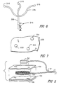
- a reference transducer assembly may include a coil or reference transducer 100' mounted between an upper or rear flexible layer 102 and a lower or front flexible layer 104.
- Double-sided adhesive tape 106 may be affixed to the bottom surface of lower layer 104 so that the entire coil assembly can be readily attached to the patient.
- One or more reference transducers 52 can be mounted on such an assembly, as on the upper layer 102.
- the reference transducers are mounted on the patient.
- the independently-positionable reference transducers also can be mounted at other locations near the patient.
- a common support arm 200 is provided to which is attached a number of flexible, goose neck arms 205 to which reference field transducers 210 are attached.
- An adjustable mounting mechanism 215 is provided for attachment of the coil carrying structure to the patient bed or other desirable location. The relative positions of the field transducers with respect to one another may be determined after they are positioned as described above. It should be appreciated that there are a number of other effective ways to attach the reference field transducers to a common support structure to allow independent movement of the transducers, such as by using bendable wire arms, arms with adjustable linkage mechanisms or other such adjustable frames.
- FIG. 7 A yet further embodiment of the present invention is shown in Fig. 7, in which a single sheet-like support 220 is provided to which reference field transducers 225 are attached.
- the sheet can be positioned over or under the patient and each of the transducers can be moved to a desired location by gathering excess material of the sheet.
- the flexible sheet can be formed of a stiff, yet sufficiently flexible material so as to allow the sheet to be bent into any desired positions to allow adjustment of the positions of the field transducers.
- Non-movable coil systems can interfere with the access of the surgeon.
- Non-movable coil systems generally cannot be positioned above the patient as they would block the lighting, and may not be positionable under the patient where a metal be would cause interference and not all beds can be replaced or retrofitted to eliminate this problem.
- high accuracy mapping volumes are too small to be useful if the coils cannot be moved from moment to moment.
- the present invention solves these problems since the reference field transducers can be positioned in a least obtrusive manner and can even be moved out of the way or to a new locale during the procedure. Moreover, the transducers can be moved closer to area of interest to provide better concentration of fields and better readings. The present invention further allows the use of even smaller reference transducers since there is no longer a need to provide large coils to generate fields over a large area to ensure broad coverage.
- the transducers can be disposable allowing easy replacement of damaged or contaminated transducers and the use of different size and types of transducers for different applications.
- a kit of such reference field transducers, with or without the calibration field transducers, can also be provided for the physician and may contain identical transducers or transducers of different sizes for different applications.
- the present invention can also be used in conjunction with the system disclosed in U.S. Application Serial No. 08/476,380, the disclosure of which is hereby incorporated by reference.
- feedback is used to adjust the currents supplied to the reference field transducers or coils to ensure that the sensor on the probe receive fields within a preselected range of magnitudes regardless of the location of the probe. This ensures that the sensor operates within its optimal range and allows the use of compact transmitters and sensors.
- the feedback techniques disclosed in the '380 application can be used with the present invention to adjust the strengths of the non-ionizing fields generated by the reference field transducers and/or the probe field transducer.
- the present invention may further be used in conjunction with the multiple probe system disclosed in the PCT application filed on even date herewith entitled "Medical Procedures And Apparatus Using Intrabody Probes" which claims the benefit of United States Provisional Applications No. 60/012,275, filed February 26, 1996; 60/011,721, filed February 15, 1996; and 60/031,824, filed November 26, 1996 and which is commonly assigned to the assignee of the present application.
- a medical probe such as a catheter is guided within the body of a patient by determining the relative dispositions of the probe relative to another probe, as by transmitting non-ionizing radiation to or from field transducers mounted on both probes.
- a site probe may be secured to a lesion within the body, and an instrument probe for treating the lesion may be guided to the lesion by monitoring relative positions of the probes.
- an instrument probe for treating the lesion may be guided to the lesion by monitoring relative positions of the probes.
- the independently movable reference field transducer arrangements of the present invention can therefore be used with the site probe/instrument probe system, with or without simultaneous patient imaging, to locate the dispositions of the probes in the frame of reference defined by the reference field transducers. So long as the dispositions of both probes are found in the same frame of reference, the relative disposition of the two probes can be determined.
- the relative dispositions can be determined properly even if the reference field transducers move relative to one another (as where the field transducers are mounted on soft tissue), provided that the system is recalibrated to update the dispositions of the field transducers relative to one another during each cycle or whenever movement occurs.
- the system can be calibrated at a particular point in the natural movement cycle (e.g., end inspiration or end expiration) and can be actuated to determine the location of a probe at the same point in the natural movement cycle.
- Such a system can also be used where superposition of the probe representation on a previously-acquired image is desired as, for example, where the image is an image acquired at the same point of the natural movement cycle.
- Superior signal-to-noise ratio performance is also achieved with the independently positionable reference field transducers of the present invention.
- a region of volume associated with the field transducers in which the signal-to-noise ratio of the assembly is optimized a so-called "optimal region"
- this optimal region will typically encompass a large area to account for all possible areas of interest. For example, a system using bed-mounted transducers may be required to locate the probe in the thorax of one patient and in the head of another patient.
- preferred embodiments of the present invention can provide enhanced signal-to-noise performance in comparison to a fixed transducer assembly using the same transducers in a large fixed array.
- the signal-to-noise performance of the system also depends on the properties of the probe transducer.
- the enhanced performance provided by preferred embodiments of the present invention can provide acceptable signal-to-noise performance with a less sensitive probe transducer, which in turn facilitates miniaturization of the probe transducer and probe.
- the benefit provided by the movable transducer assembly can permit use of smaller, cheaper and less obtrusive reference transducers while maintaining satisfactory performance.
- the reference field transducers can be positioned to provide optimum performance in that region without obstructing the physician's access to the patient.
- the reference assemblies can be placed on the back, top and right side of the head.
- Yet another advantage of the embodiments disclosed herein is the ability to provide adjustment of the reference field transducers if they are moved or if the initial positioning of the reference field transducers yields poor readings. Thus, the surgeon can relocate the reference assemblies, or even add additional reference assemblies, during a procedure.
- the method of using calibration field transducers for calibrating the relative positions of the reference transducers with respect to one another in accordance with the present invention can also be used to replace or augment the manner of determining the relative positions of the linked reference field transducers. Namely, instead of including a rotation measuring device, such as an optical encoder device, which allows the angle between transducer-carrying arms to be accurately determined so that the relative positions of reference field transducers are known, calibration field transducers can be used as disclosed herein.
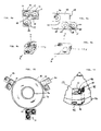
- a three-axis coil sensor is formed by providing three separate calibration coils 12, 14 and 16 on a single, solitary planar base panel 10.
- Base panel 10 can be formed from non-ferromagnetic materials such as polymers, non-ferromagnetic metals and other materials conventionally used in disposable medical devices.
- the base panel is formed from a polyimide.
- the base panel 2 is initially provided in a flat, planar configuration as shown in Fig. 8a.
- Calibration coils 4, 6, and 8 are then affixed to subpanels 13, 15 and 17 which in turn comprise base panel 2.
- the calibration coils are preferably constructed by winding fine gauge wire around a bobbin, removing the bobbin and laminating the remaining wire coil directly onto the base panel. Alternately, the bobbin can be left in place and affixed to the base panel with the coil.
- each calibration field transducer is therefore adapted to detect magnetic field components in three mutually orthogonal directions.
- coils 22, 24 and 26 are formed on subpanels 21, 23 and 25 forming base panel 20.
- the folding of the panel 20 along fold lines 27 and 28 again produces a 3-axis coil assembly where the three coils are mutually orthogonal to one another but with one of the coils being offset by a small distance from the other two coils, as shown in Fig. 8b.
- the present invention incorporates three, three-axis coil sensors 30, 31, 32 attached to the outer periphery 33 of a main planar substrate 36.
- a main coil 35 is provided on a main planar substrate 36.
- the main coil can be used like reference field transducer 100 described in the embodiment of Figs. 1-4.
- each base panel carrying each 3-axis sensor and the planar substrate 36 are formed as one single substrate, and appropriate fold lines are provided in the base panels and at the edge where the base panels attach to the outer periphery of the main planar substrate 36 to allow the calibration coils to be folded such that they are disposed orthogonal to one another along their x, y and z axes.
- each 3-axis sensor is positioned approximately 120 degrees apart from another spaced about the main coil 35.
- Main coil 35 is preferably fabricated from approximately 800 to 1600 turns and preferably 1550 turns of 27 gauge wire or less to form coil with a diameter of 76.2 mm (3 inches) or less, and preferably 58.9 mm (2.32 inches).
- Each individual calibration coil of each three-coil sensor 30, 31, 32 is preferably fabricated from approximately 1400 to 2200 turns, and preferably 2000 turns of 46 gauge wire to form a coil with an outside diameter of 12.7 mm (0.5 inches) or less, and preferably 8.1 mm (0.32 inches).
- the coils can be formed by other techniques such as printing the coils directly on the substrates.
- Lead wires (not shown) are provided to connect the coils to the appropriate electronics such as driver and amplifiers.
- the leads can constitute external wires, conductors within the substrates of conductors printed on the surface of the substrates.
- the reference transducer assembly of Fig. 10 which includes main coil 35 as well as calibration coils 30, 31, 32 attached to the same panel as the main coil, can replace the entire reference transducer assembly 50 of the embodiment described in Figs. 1-4.
- Fig. 11 is a fragmented view of a portion of a main coil and shows the placement of a 3-axis coil on a portion of the substrate carrying the main coil.
- the 3-axis coil assembly 40 is assembled in a manner similar to the assembly of the 3-axis coil sensor assembly shown in Figs. 8a and 8b.
- the three coil assembly is adapted to be inserted into recesses 41 and 42 provided on a main planar substrate 46.
- Recess 41 is adapted to accept any slightly protruding portions of coils 50 and 51 while recess 42 is formed to accept the outward protrusion of coil 52.
- main coil 45 is formed on the same substrate in which recesses 42 and 41 are formed; namely, substrate 46.
- the coil assemblies of the present invention are particularly adapted to be used in connection with the individually positionable transducer assemblies disclosed in the earlier embodiments.
- the coil sensor assemblies of Figs. 7b and 8b can be used as the calibration field transducers 316 and positioned within calibration transducer sockets 314 of Figs. 1-4.
Description
Claims (9)
- A foldable reference field transducer (50) assembly comprising:(a) a main coil (100) provided on a main planar substrate (36), said main planar substrate having an outer peripheral edge (33), and(b) one or more three-axis magnetic field sensing elements (30,31,32) each comprisingcharacterised in that at least a portion of said base panel is attached to said outer peripheral edge of said main planar substrate.(i) an initially planar base panel (2) having at least three element-carrying subpanels (13, 15, 17) separated from one another by one or more fold lines (17, 18) in said base panel, and(ii) three calibration elements (4, 6, 8) each positioned on a respective one of said element-carrying subpanels, whereby the folding of at least two of said subpanels at said fold lines allows said calibration elements to be positioned along three mutually orthogonal axes upon set-up of said three-axis sensors,
- A foldable reference field transducer assembly (50) as claimed in claim 1, wherein each of said base panels is initially coplanar with said main planar substrate prior to set-up of said three-axis sensors.
- A system for determining the disposition of a probe (20) within the body of a patient, comprising:wherein each said reference field transducer is a reference field transducer according to claim 1.(a) a probe (20) having one or more probe field transducers (30) mounted thereon;(b) a plurality of reference field transducers (50) independently movable with respect to one another and locatable in desired, customizable positions with respect to the body of the patient;(c) calibration means (316) for determining the relative dispositions of said field transducers with respect to one another while said reference field transducers are located in their desired positions;(d) transmission means (80) to actuate said reference field transducers and said one or more probe field transducers to transmit one or more non-ionizing fields and detect the transmitted field, so that each such field is transmitted by one element of a transmitter-receiver pair including a reference field transducer and a probe field transducer, and detected by the other element of such pair; and(e) calculation means (85) to determine the relative disposition of the probe with respect to said reference field transducers from properties of the detected fields and from the relative dispositions of said reference field transducers with respect to one another;
- A method for determining the disposition of a probe within the body of a patient, comprising the steps of:(a) providing a probe (20) having one or more probe field transducers (30) mounted thereon;(b) positioning a plurality of reference field transducers (50) according to claim 1 independently with respect to one another in desired, customizable positions with respect to the body of the patient;(c) determining the relative dispositions of said reference field transducers with respect to one another while said reference field transducers are located in their desired positions;(d) transmitting one or more non-ionizing fields between said probe field transducers and said reference field transducers and detecting each such transmitted field so that each such field is transmitted by one element of a transmitter-receiver pair including a reference field transducer and a probe field transducer, and detected by the other element of such pair; and(e) determining the relative disposition of the probe with respect to said reference field transducers from properties of the detected fields and from the relative dispositions of said reference field transducers with respect to one another.
- Apparatus for generating non-ionizing fields inside the body of a patient, comprising:(a) a plurality of reference field transducers (50) according to claim 1, and(b) means for positioning each of said reference field transducers independently with respect to one another to desired, customizable positions in close proximity to the body of the patient.
- A kit comprising a plurality of separate reference assemblies each including a field transducer (50) according to claim 1 for generating or detecting non-ionizing fields and means (310) for securing the transducer assembly to the body of a medical patient independently of the other reference assemblies.
- A reference transducer assembly for mounting on the body of a medical patient comprising a structure, a reference field transducer (50) according to claim 1 for generating or detecting non-ionizing fields mounted to said structure, means for holding one or more calibration field transducers adapted to generate or detect a non-ionizing field in a predetermined dispositions relative to the structure, and means (310) for securing the structure to the body of the patient.
- A reference transducer assembly for mounting on the body of a medical patient comprising a structure, a reference field transducer (50) according to claim 1 for generating or detecting non-ionizing fields mounted to said structure, means for securing the structure to the body of the patient, and means for limiting heating of the patient by the heat generated in said reference field transducer.
- An assembly as claimed in claim 8 wherein said reference field transducer (50) includes one or more coils (100).
Applications Claiming Priority (3)
| Application Number | Priority Date | Filing Date | Title |
|---|---|---|---|
| US7985898P | 1998-03-30 | 1998-03-30 | |
| US79858P | 1998-03-30 | ||
| PCT/US1999/006256 WO1999049783A1 (en) | 1998-03-30 | 1999-03-22 | Three-axis coil sensor |
Publications (2)
| Publication Number | Publication Date |
|---|---|
| EP1067863A1 EP1067863A1 (en) | 2001-01-17 |
| EP1067863B1 true EP1067863B1 (en) | 2005-12-07 |
Family
ID=22153250
Family Applications (1)
| Application Number | Title | Priority Date | Filing Date |
|---|---|---|---|
| EP99914039A Expired - Lifetime EP1067863B1 (en) | 1998-03-30 | 1999-03-22 | Three-axis coil sensor |
Country Status (9)
| Country | Link |
|---|---|
| US (1) | US6161032A (en) |
| EP (1) | EP1067863B1 (en) |
| JP (1) | JP4156195B2 (en) |
| AU (1) | AU3197699A (en) |
| CA (1) | CA2325540C (en) |
| DE (1) | DE69928783T2 (en) |
| ES (1) | ES2253882T3 (en) |
| IL (1) | IL138369A (en) |
| WO (1) | WO1999049783A1 (en) |
Cited By (1)
| Publication number | Priority date | Publication date | Assignee | Title |
|---|---|---|---|---|
| US10677857B2 (en) | 2017-12-15 | 2020-06-09 | Biosense Webster (Israel) Ltd. | Three-axial sensor including six single-axis sensors |
Families Citing this family (206)
| Publication number | Priority date | Publication date | Assignee | Title |
|---|---|---|---|---|
| FR2652928B1 (en) | 1989-10-05 | 1994-07-29 | Diadix Sa | INTERACTIVE LOCAL INTERVENTION SYSTEM WITHIN A AREA OF A NON-HOMOGENEOUS STRUCTURE. |
| ES2115776T3 (en) | 1992-08-14 | 1998-07-01 | British Telecomm | POSITION LOCATION SYSTEM. |
| US5803089A (en) | 1994-09-15 | 1998-09-08 | Visualization Technology, Inc. | Position tracking and imaging system for use in medical applications |
| US6226548B1 (en) | 1997-09-24 | 2001-05-01 | Surgical Navigation Technologies, Inc. | Percutaneous registration apparatus and method for use in computer-assisted surgical navigation |
| US6021343A (en) | 1997-11-20 | 2000-02-01 | Surgical Navigation Technologies | Image guided awl/tap/screwdriver |
| US6348058B1 (en) | 1997-12-12 | 2002-02-19 | Surgical Navigation Technologies, Inc. | Image guided spinal surgery guide, system, and method for use thereof |
| US20030036746A1 (en) | 2001-08-16 | 2003-02-20 | Avi Penner | Devices for intrabody delivery of molecules and systems and methods utilizing same |
| US6477400B1 (en) | 1998-08-20 | 2002-11-05 | Sofamor Danek Holdings, Inc. | Fluoroscopic image guided orthopaedic surgery system with intraoperative registration |
| EP1161691A2 (en) | 1998-12-23 | 2001-12-12 | Peter D. Jakab | Magnetic resonance scanner with electromagnetic position and orientation tracking device |
| US7575550B1 (en) | 1999-03-11 | 2009-08-18 | Biosense, Inc. | Position sensing based on ultrasound emission |
| US7590441B2 (en) | 1999-03-11 | 2009-09-15 | Biosense, Inc. | Invasive medical device with position sensing and display |
| US7558616B2 (en) * | 1999-03-11 | 2009-07-07 | Biosense, Inc. | Guidance of invasive medical procedures using implantable tags |
| US7549960B2 (en) * | 1999-03-11 | 2009-06-23 | Biosense, Inc. | Implantable and insertable passive tags |
| US7174201B2 (en) * | 1999-03-11 | 2007-02-06 | Biosense, Inc. | Position sensing system with integral location pad and position display |
| US6470207B1 (en) | 1999-03-23 | 2002-10-22 | Surgical Navigation Technologies, Inc. | Navigational guidance via computer-assisted fluoroscopic imaging |
| US6491699B1 (en) | 1999-04-20 | 2002-12-10 | Surgical Navigation Technologies, Inc. | Instrument guidance method and system for image guided surgery |
| US9572519B2 (en) * | 1999-05-18 | 2017-02-21 | Mediguide Ltd. | Method and apparatus for invasive device tracking using organ timing signal generated from MPS sensors |
| US7126450B2 (en) | 1999-06-21 | 2006-10-24 | Access Business Group International Llc | Inductively powered apparatus |
| US6825620B2 (en) | 1999-06-21 | 2004-11-30 | Access Business Group International Llc | Inductively coupled ballast circuit |
| US6626899B2 (en) | 1999-06-25 | 2003-09-30 | Nidus Medical, Llc | Apparatus and methods for treating tissue |
| US11331150B2 (en) | 1999-10-28 | 2022-05-17 | Medtronic Navigation, Inc. | Method and apparatus for surgical navigation |
| US6747539B1 (en) | 1999-10-28 | 2004-06-08 | Michael A. Martinelli | Patient-shielding and coil system |
| US6474341B1 (en) | 1999-10-28 | 2002-11-05 | Surgical Navigation Technologies, Inc. | Surgical communication and power system |
| AU1240801A (en) | 1999-10-28 | 2001-05-08 | Enterprise Medical Technology, Inc. | Coil structures and methods for generating magnetic fields |
| US6493573B1 (en) | 1999-10-28 | 2002-12-10 | Winchester Development Associates | Method and system for navigating a catheter probe in the presence of field-influencing objects |
| US7366562B2 (en) * | 2003-10-17 | 2008-04-29 | Medtronic Navigation, Inc. | Method and apparatus for surgical navigation |
| US8644907B2 (en) | 1999-10-28 | 2014-02-04 | Medtronic Navigaton, Inc. | Method and apparatus for surgical navigation |
| US6381485B1 (en) | 1999-10-28 | 2002-04-30 | Surgical Navigation Technologies, Inc. | Registration of human anatomy integrated for electromagnetic localization |
| US6499488B1 (en) | 1999-10-28 | 2002-12-31 | Winchester Development Associates | Surgical sensor |
| US8239001B2 (en) | 2003-10-17 | 2012-08-07 | Medtronic Navigation, Inc. | Method and apparatus for surgical navigation |
| WO2001064124A1 (en) | 2000-03-01 | 2001-09-07 | Surgical Navigation Technologies, Inc. | Multiple cannula image guided tool for image guided procedures |
| US6535756B1 (en) | 2000-04-07 | 2003-03-18 | Surgical Navigation Technologies, Inc. | Trajectory storage apparatus and method for surgical navigation system |
| US7085400B1 (en) | 2000-06-14 | 2006-08-01 | Surgical Navigation Technologies, Inc. | System and method for image based sensor calibration |
| US7809421B1 (en) * | 2000-07-20 | 2010-10-05 | Biosense, Inc. | Medical system calibration with static metal compensation |
| US6564158B1 (en) * | 2000-08-17 | 2003-05-13 | Holaday Industries, Inc. | Broadband electromagnetic field component measurement system |
| JP2004505748A (en) | 2000-08-23 | 2004-02-26 | ミクロニックス ピーティーワイ リミテッド | Catheter position display device and use thereof |
| US6820614B2 (en) | 2000-12-02 | 2004-11-23 | The Bonutti 2003 Trust -A | Tracheal intubination |
| US7210223B2 (en) | 2000-12-13 | 2007-05-01 | Image-Guided Neurologics, Inc. | Method of manufacturing a microcoil construction |
| US6792303B2 (en) * | 2001-05-11 | 2004-09-14 | Scimed Life Systems, Inc. | Apparatus for improved sensor accuracy |
| US6636757B1 (en) | 2001-06-04 | 2003-10-21 | Surgical Navigation Technologies, Inc. | Method and apparatus for electromagnetic navigation of a surgical probe near a metal object |
| US7383073B1 (en) * | 2001-10-16 | 2008-06-03 | Z-Kat Inc. | Digital minimally invasive surgery system |
| US6947786B2 (en) | 2002-02-28 | 2005-09-20 | Surgical Navigation Technologies, Inc. | Method and apparatus for perspective inversion |
| US11202676B2 (en) | 2002-03-06 | 2021-12-21 | Mako Surgical Corp. | Neural monitor-based dynamic haptics |
| US8010180B2 (en) | 2002-03-06 | 2011-08-30 | Mako Surgical Corp. | Haptic guidance system and method |
| US8996169B2 (en) | 2011-12-29 | 2015-03-31 | Mako Surgical Corp. | Neural monitor-based dynamic haptics |
| WO2003077101A2 (en) | 2002-03-06 | 2003-09-18 | Z-Kat, Inc. | System and method for using a haptic device in combination with a computer-assisted surgery system |
| US6990368B2 (en) | 2002-04-04 | 2006-01-24 | Surgical Navigation Technologies, Inc. | Method and apparatus for virtual digital subtraction angiography |
| US7998062B2 (en) | 2004-03-29 | 2011-08-16 | Superdimension, Ltd. | Endoscope structures and techniques for navigating to a target in branched structure |
| WO2004016178A2 (en) * | 2002-08-16 | 2004-02-26 | Orthosoft Inc. | Interface apparatus for passive tracking systems and method of use thereof |
| US20040068178A1 (en) * | 2002-09-17 | 2004-04-08 | Assaf Govari | High-gradient recursive locating system |
| WO2004046754A2 (en) * | 2002-11-14 | 2004-06-03 | General Electric Medical Systems Global Technology Company, Llc | Interchangeable localizing devices for use with tracking systems |
| US7599730B2 (en) | 2002-11-19 | 2009-10-06 | Medtronic Navigation, Inc. | Navigation system for cardiac therapies |
| US7697972B2 (en) | 2002-11-19 | 2010-04-13 | Medtronic Navigation, Inc. | Navigation system for cardiac therapies |
| US7660623B2 (en) | 2003-01-30 | 2010-02-09 | Medtronic Navigation, Inc. | Six degree of freedom alignment display for medical procedures |
| US7542791B2 (en) | 2003-01-30 | 2009-06-02 | Medtronic Navigation, Inc. | Method and apparatus for preplanning a surgical procedure |
| US7519413B1 (en) | 2003-02-20 | 2009-04-14 | S.A. Instruments, Inc. | Apparatus and method for measuring motion in a strong magnetic field |
| US7314448B2 (en) * | 2003-03-28 | 2008-01-01 | Scimed Life Systems, Inc. | Imaging transducer assembly |
| WO2004095044A1 (en) * | 2003-04-22 | 2004-11-04 | Philips Intellectual Property & Standards Gmbh | Multiscale localization procedure |
| AU2003902259A0 (en) * | 2003-05-13 | 2003-05-29 | Telezygology Inc. | Improved assembly system |
| US7090639B2 (en) * | 2003-05-29 | 2006-08-15 | Biosense, Inc. | Ultrasound catheter calibration system |
| US7158754B2 (en) | 2003-07-01 | 2007-01-02 | Ge Medical Systems Global Technology Company, Llc | Electromagnetic tracking system and method using a single-coil transmitter |
| JP2005052637A (en) * | 2003-07-18 | 2005-03-03 | Pentax Corp | Capsule type device and capsule type device driving control system |
| US20050027195A1 (en) * | 2003-08-01 | 2005-02-03 | Assaf Govari | Calibration data compression |
| US7313430B2 (en) * | 2003-08-28 | 2007-12-25 | Medtronic Navigation, Inc. | Method and apparatus for performing stereotactic surgery |
| GB0320787D0 (en) * | 2003-09-05 | 2003-10-08 | Depuy Int Ltd | Flexible image guided surgery marker |
| EP2113189B1 (en) | 2003-09-15 | 2013-09-04 | Covidien LP | System of accessories for use with bronchoscopes |
| EP2316328B1 (en) | 2003-09-15 | 2012-05-09 | Super Dimension Ltd. | Wrap-around holding device for use with bronchoscopes |
| US7835778B2 (en) | 2003-10-16 | 2010-11-16 | Medtronic Navigation, Inc. | Method and apparatus for surgical navigation of a multiple piece construct for implantation |
| US7840253B2 (en) | 2003-10-17 | 2010-11-23 | Medtronic Navigation, Inc. | Method and apparatus for surgical navigation |
| JP4150663B2 (en) * | 2003-12-25 | 2008-09-17 | オリンパス株式会社 | In-subject position detection system |
| US7966058B2 (en) * | 2003-12-31 | 2011-06-21 | General Electric Company | System and method for registering an image with a representation of a probe |
| US8764725B2 (en) | 2004-02-09 | 2014-07-01 | Covidien Lp | Directional anchoring mechanism, method and applications thereof |
| EP1720480A1 (en) | 2004-03-05 | 2006-11-15 | Hansen Medical, Inc. | Robotic catheter system |
| US7976539B2 (en) | 2004-03-05 | 2011-07-12 | Hansen Medical, Inc. | System and method for denaturing and fixing collagenous tissue |
| US20050209524A1 (en) * | 2004-03-10 | 2005-09-22 | General Electric Company | System and method for receiving and storing information pertaining to a patient |
| WO2005092188A1 (en) * | 2004-03-29 | 2005-10-06 | Olympus Corporation | System for detecting position in examinee |
| JP4054319B2 (en) * | 2004-03-29 | 2008-02-27 | オリンパス株式会社 | Power supply |
| JP4488294B2 (en) * | 2004-03-29 | 2010-06-23 | オリンパス株式会社 | In-subject position detection system |
| US20050228251A1 (en) * | 2004-03-30 | 2005-10-13 | General Electric Company | System and method for displaying a three-dimensional image of an organ or structure inside the body |
| US20050228252A1 (en) * | 2004-04-02 | 2005-10-13 | General Electric Company | Electrophysiology system and method |
| US20050222509A1 (en) * | 2004-04-02 | 2005-10-06 | General Electric Company | Electrophysiology system and method |
| US7567834B2 (en) | 2004-05-03 | 2009-07-28 | Medtronic Navigation, Inc. | Method and apparatus for implantation between two vertebral bodies |
| EP1758642A2 (en) * | 2004-06-01 | 2007-03-07 | Remon Medical Technologies Ltd. | System for evaluating heart performance |
| US20060064133A1 (en) | 2004-09-17 | 2006-03-23 | Cardiac Pacemakers, Inc. | System and method for deriving relative physiologic measurements using an external computing device |
| US20060084863A1 (en) * | 2004-10-15 | 2006-04-20 | Jacek Kluzik | Positional verification |
| EP1647236A1 (en) * | 2004-10-15 | 2006-04-19 | BrainLAB AG | Apparatus and method for the position checking of markers |
| US7813808B1 (en) | 2004-11-24 | 2010-10-12 | Remon Medical Technologies Ltd | Implanted sensor system with optimized operational and sensing parameters |
| US7684850B2 (en) * | 2005-01-07 | 2010-03-23 | Biosense Webster, Inc. | Reference catheter for impedance calibration |
| US7869865B2 (en) * | 2005-01-07 | 2011-01-11 | Biosense Webster, Inc. | Current-based position sensing |
| US7976518B2 (en) | 2005-01-13 | 2011-07-12 | Corpak Medsystems, Inc. | Tubing assembly and signal generator placement control device and method for use with catheter guidance systems |
| US20060241397A1 (en) * | 2005-02-22 | 2006-10-26 | Assaf Govari | Reference pad for position sensing |
| US7505816B2 (en) * | 2005-04-29 | 2009-03-17 | Medtronic, Inc. | Actively cooled external energy source, external charger, system of transcutaneous energy transfer, system of transcutaneous charging and method therefore |
| EP1906858B1 (en) | 2005-07-01 | 2016-11-16 | Hansen Medical, Inc. | Robotic catheter system |
| US7742815B2 (en) | 2005-09-09 | 2010-06-22 | Cardiac Pacemakers, Inc. | Using implanted sensors for feedback control of implanted medical devices |
| US7835784B2 (en) | 2005-09-21 | 2010-11-16 | Medtronic Navigation, Inc. | Method and apparatus for positioning a reference frame |
| WO2007047599A2 (en) * | 2005-10-18 | 2007-04-26 | Tursiop Technologies, Llc | Method and apparatus for high-gain magnetic resonance imaging |
| JP5451076B2 (en) * | 2005-12-15 | 2014-03-26 | コーニンクレッカ フィリップス エヌ ヴェ | Electromagnetic tracking method and apparatus for metal artifact compensation using a modular array of reference sensors. |
| US20070167741A1 (en) | 2005-12-30 | 2007-07-19 | Sherman Jason T | Apparatus and method for registering a bone of a patient with a computer assisted orthopaedic surgery system |
| US8862200B2 (en) | 2005-12-30 | 2014-10-14 | DePuy Synthes Products, LLC | Method for determining a position of a magnetic source |
| US7525309B2 (en) | 2005-12-30 | 2009-04-28 | Depuy Products, Inc. | Magnetic sensor array |
| US7816915B2 (en) * | 2006-01-06 | 2010-10-19 | Biosense Webster, Inc. | Miniature coils on core with printed circuit |
| US20070225595A1 (en) * | 2006-01-17 | 2007-09-27 | Don Malackowski | Hybrid navigation system for tracking the position of body tissue |
| US9168102B2 (en) | 2006-01-18 | 2015-10-27 | Medtronic Navigation, Inc. | Method and apparatus for providing a container to a sterile environment |
| US7471202B2 (en) | 2006-03-29 | 2008-12-30 | General Electric Co. | Conformal coil array for a medical tracking system |
| US7532997B2 (en) | 2006-04-17 | 2009-05-12 | General Electric Company | Electromagnetic tracking using a discretized numerical field model |
| US8112292B2 (en) | 2006-04-21 | 2012-02-07 | Medtronic Navigation, Inc. | Method and apparatus for optimizing a therapy |
| US20070265526A1 (en) * | 2006-05-11 | 2007-11-15 | Assaf Govari | Low-profile location pad |
| DE502006002064D1 (en) * | 2006-05-16 | 2008-12-24 | Brainlab Ag | Medical basin positioning and tracking device |
| WO2007136769A2 (en) | 2006-05-19 | 2007-11-29 | Mako Surgical Corp. | Method and apparatus for controlling a haptic device |
| DE102006029122A1 (en) * | 2006-06-22 | 2007-12-27 | Amedo Gmbh | System for determining the position of a medical instrument |
| US7955268B2 (en) | 2006-07-21 | 2011-06-07 | Cardiac Pacemakers, Inc. | Multiple sensor deployment |
| US8197494B2 (en) | 2006-09-08 | 2012-06-12 | Corpak Medsystems, Inc. | Medical device position guidance system with wireless connectivity between a noninvasive device and an invasive device |
| US8660635B2 (en) | 2006-09-29 | 2014-02-25 | Medtronic, Inc. | Method and apparatus for optimizing a computer assisted surgical procedure |
| US20080108991A1 (en) * | 2006-11-08 | 2008-05-08 | General Electric Company | Method and apparatus for performing pedicle screw fusion surgery |
| AU2007350982A1 (en) | 2006-11-10 | 2008-10-23 | Dorian Averbuch | Adaptive navigation technique for navigating a catheter through a body channel or cavity |
| DE102006059225A1 (en) * | 2006-12-13 | 2008-06-26 | Wittenstein Ag | Medical device for determining the position of intracorporeal implants |
| US8068648B2 (en) | 2006-12-21 | 2011-11-29 | Depuy Products, Inc. | Method and system for registering a bone of a patient with a computer assisted orthopaedic surgery system |
| US20080167639A1 (en) * | 2007-01-08 | 2008-07-10 | Superdimension Ltd. | Methods for localized intra-body treatment of tissue |
| US9549689B2 (en) | 2007-03-09 | 2017-01-24 | St. Jude Medical, Atrial Fibrillation Division, Inc. | System and method for correction of inhomogeneous fields |
| US10433929B2 (en) | 2007-03-09 | 2019-10-08 | St. Jude Medical, Atrial Fibrillation Division, Inc. | System and method for local deformable registration of a catheter navigation system to image data or a model |
| WO2009074872A2 (en) * | 2007-07-09 | 2009-06-18 | Superdimension, Ltd. | Patent breathing modeling |
| US8905920B2 (en) | 2007-09-27 | 2014-12-09 | Covidien Lp | Bronchoscope adapter and method |
| DE102007047021B4 (en) * | 2007-10-01 | 2011-07-28 | Siemens AG, 80333 | Arrangement for transmitting magnetic resonance signals |
| US8391952B2 (en) | 2007-10-11 | 2013-03-05 | General Electric Company | Coil arrangement for an electromagnetic tracking system |
| JP2010187708A (en) * | 2008-01-10 | 2010-09-02 | Univ Of Tokushima | Jaw movement measuring device and method for manufacturing sensor coil for use in the same |
| JP5211177B2 (en) | 2008-02-11 | 2013-06-12 | カーディアック ペースメイカーズ, インコーポレイテッド | Hemodynamic monitoring method for rhythm discrimination in the heart |
| WO2009102640A1 (en) | 2008-02-12 | 2009-08-20 | Cardiac Pacemakers, Inc. | Systems and methods for controlling wireless signal transfers between ultrasound-enabled medical devices |
| DE102008012342A1 (en) * | 2008-03-03 | 2009-09-10 | Siemens Aktiengesellschaft | medicine system |
| WO2009122273A2 (en) | 2008-04-03 | 2009-10-08 | Superdimension, Ltd. | Magnetic interference detection system and method |
| US9579161B2 (en) * | 2008-05-06 | 2017-02-28 | Medtronic Navigation, Inc. | Method and apparatus for tracking a patient |
| US8218846B2 (en) | 2008-05-15 | 2012-07-10 | Superdimension, Ltd. | Automatic pathway and waypoint generation and navigation method |
| EP2297673B1 (en) | 2008-06-03 | 2020-04-22 | Covidien LP | Feature-based registration method |
| US8218847B2 (en) * | 2008-06-06 | 2012-07-10 | Superdimension, Ltd. | Hybrid registration method |
| US8932207B2 (en) | 2008-07-10 | 2015-01-13 | Covidien Lp | Integrated multi-functional endoscopic tool |
| US8165658B2 (en) | 2008-09-26 | 2012-04-24 | Medtronic, Inc. | Method and apparatus for positioning a guide relative to a base |
| EP2334230A1 (en) | 2008-10-10 | 2011-06-22 | Cardiac Pacemakers, Inc. | Systems and methods for determining cardiac output using pulmonary artery pressure measurements |
| WO2010059291A1 (en) | 2008-11-19 | 2010-05-27 | Cardiac Pacemakers, Inc. | Assessment of pulmonary vascular resistance via pulmonary artery pressure |
| US8483800B2 (en) * | 2008-11-29 | 2013-07-09 | General Electric Company | Surgical navigation enabled imaging table environment |
| WO2010063117A1 (en) | 2008-12-02 | 2010-06-10 | Andre Novomir Hladio | Method and system for aligning a prosthesis during surgery using active sensors |
| US8175681B2 (en) | 2008-12-16 | 2012-05-08 | Medtronic Navigation Inc. | Combination of electromagnetic and electropotential localization |
| US8611984B2 (en) | 2009-04-08 | 2013-12-17 | Covidien Lp | Locatable catheter |
| US9254123B2 (en) | 2009-04-29 | 2016-02-09 | Hansen Medical, Inc. | Flexible and steerable elongate instruments with shape control and support elements |
| DE102009021025A1 (en) * | 2009-05-13 | 2010-11-25 | Siemens Aktiengesellschaft | Medical navigation system |
| US20110199077A1 (en) * | 2010-02-15 | 2011-08-18 | Gary Bergstrom | Ferrous object detector |
| US20110218940A1 (en) * | 2009-07-28 | 2011-09-08 | Recharge Power Llc | Parking Meter System |
| US20110028848A1 (en) * | 2009-07-31 | 2011-02-03 | Cem Shaquer | Methods and Apparatus for Detecting and Mapping Tissue Interfaces |
| US8494613B2 (en) | 2009-08-31 | 2013-07-23 | Medtronic, Inc. | Combination localization system |
| US8494614B2 (en) | 2009-08-31 | 2013-07-23 | Regents Of The University Of Minnesota | Combination localization system |
| US8207651B2 (en) | 2009-09-16 | 2012-06-26 | Tyco Healthcare Group Lp | Low energy or minimum disturbance method for measuring frequency response functions of ultrasonic surgical devices in determining optimum operating point |
| WO2011092594A2 (en) | 2010-02-01 | 2011-08-04 | Superdimension, Ltd. | Region-growing algorithm |
| US9107684B2 (en) * | 2010-03-05 | 2015-08-18 | Covidien Lp | System and method for transferring power to intrabody instruments |
| US8483802B2 (en) | 2010-03-25 | 2013-07-09 | Medtronic, Inc. | Method and apparatus for guiding an external needle to an implantable device |
| US9216257B2 (en) | 2010-03-25 | 2015-12-22 | Medtronic, Inc. | Method and apparatus for guiding an external needle to an implantable device |
| US8475407B2 (en) | 2010-03-25 | 2013-07-02 | Medtronic, Inc. | Method and apparatus for guiding an external needle to an implantable device |
| US9339601B2 (en) * | 2010-03-25 | 2016-05-17 | Medtronic, Inc. | Method and apparatus for guiding an external needle to an implantable device |
| JP5558902B2 (en) * | 2010-04-28 | 2014-07-23 | 日立コンシューマエレクトロニクス株式会社 | Motor function analyzer |
| WO2011159834A1 (en) | 2010-06-15 | 2011-12-22 | Superdimension, Ltd. | Locatable expandable working channel and method |
| US8657809B2 (en) * | 2010-09-29 | 2014-02-25 | Stryker Leibinger Gmbh & Co., Kg | Surgical navigation system |
| CN103402450A (en) | 2010-12-17 | 2013-11-20 | 阿韦尼尔医药公司 | Method and system for aligning a prosthesis during surgery |
| US20120191079A1 (en) | 2011-01-20 | 2012-07-26 | Hansen Medical, Inc. | System and method for endoluminal and translumenal therapy |
| WO2012149548A2 (en) * | 2011-04-29 | 2012-11-01 | The Johns Hopkins University | System and method for tracking and navigation |
| US20130030363A1 (en) | 2011-07-29 | 2013-01-31 | Hansen Medical, Inc. | Systems and methods utilizing shape sensing fibers |
| US9028441B2 (en) | 2011-09-08 | 2015-05-12 | Corpak Medsystems, Inc. | Apparatus and method used with guidance system for feeding and suctioning |
| EP2765946B1 (en) * | 2011-10-13 | 2015-08-12 | Brainlab AG | Medical tracking system comprising multi-functional sensor device |
| EP3335662B1 (en) * | 2011-10-13 | 2020-08-19 | Brainlab AG | Medical tracking system comprising two or more communicating sensor devices |
| US10238837B2 (en) | 2011-10-14 | 2019-03-26 | Intuitive Surgical Operations, Inc. | Catheters with control modes for interchangeable probes |
| US9387048B2 (en) | 2011-10-14 | 2016-07-12 | Intuitive Surgical Operations, Inc. | Catheter sensor systems |
| US9452276B2 (en) | 2011-10-14 | 2016-09-27 | Intuitive Surgical Operations, Inc. | Catheter with removable vision probe |
| US20130303944A1 (en) | 2012-05-14 | 2013-11-14 | Intuitive Surgical Operations, Inc. | Off-axis electromagnetic sensor |
| US9314188B2 (en) | 2012-04-12 | 2016-04-19 | Intellijoint Surgical Inc. | Computer-assisted joint replacement surgery and navigation systems |
| US20140148673A1 (en) | 2012-11-28 | 2014-05-29 | Hansen Medical, Inc. | Method of anchoring pullwire directly articulatable region in catheter |
| US9204820B2 (en) | 2012-12-31 | 2015-12-08 | Biosense Webster (Israel) Ltd. | Catheter with combined position and pressure sensing structures |
| US9204841B2 (en) | 2012-12-31 | 2015-12-08 | Biosense Webster (Israel) Ltd. | Catheter with serially connected sensing structures and methods of calibration and detection |
| US9468397B2 (en) | 2013-01-23 | 2016-10-18 | St. Jude Medical, Atrial Fibrillation Division, Inc. | Distributed location sensor |
| US20140277334A1 (en) | 2013-03-14 | 2014-09-18 | Hansen Medical, Inc. | Active drives for robotic catheter manipulators |
| US9326822B2 (en) | 2013-03-14 | 2016-05-03 | Hansen Medical, Inc. | Active drives for robotic catheter manipulators |
| US20140276936A1 (en) | 2013-03-15 | 2014-09-18 | Hansen Medical, Inc. | Active drive mechanism for simultaneous rotation and translation |
| US9408669B2 (en) | 2013-03-15 | 2016-08-09 | Hansen Medical, Inc. | Active drive mechanism with finite range of motion |
| US9247998B2 (en) | 2013-03-15 | 2016-02-02 | Intellijoint Surgical Inc. | System and method for intra-operative leg position measurement |
| CN105208911B (en) * | 2013-06-05 | 2017-08-18 | 切克-卡普有限公司 | The location estimation of imaging capsule in the gastrointestinal tract |
| DE102013211703A1 (en) * | 2013-06-20 | 2014-12-24 | Evonik Röhm Gmbh | Personalized detection system for detecting magnetic objects in the human organism |
| DE102013221026A1 (en) * | 2013-10-16 | 2015-04-16 | Fiagon Gmbh | Field generator and position detection system |
| DE102013222230A1 (en) | 2013-10-31 | 2015-04-30 | Fiagon Gmbh | Surgical instrument |
| US10046140B2 (en) | 2014-04-21 | 2018-08-14 | Hansen Medical, Inc. | Devices, systems, and methods for controlling active drive systems |
| US10952593B2 (en) | 2014-06-10 | 2021-03-23 | Covidien Lp | Bronchoscope adapter |
| US9403657B2 (en) | 2014-07-07 | 2016-08-02 | Precision, Inc. | Angular winding |
| EP3166490B1 (en) * | 2014-07-10 | 2022-11-16 | Given Imaging Ltd. | Sensor belt configured to localize an in-vivo device and method for localization |
| US10426555B2 (en) | 2015-06-03 | 2019-10-01 | Covidien Lp | Medical instrument with sensor for use in a system and method for electromagnetic navigation |
| US9962134B2 (en) | 2015-10-28 | 2018-05-08 | Medtronic Navigation, Inc. | Apparatus and method for maintaining image quality while minimizing X-ray dosage of a patient |
| FR3048512B1 (en) * | 2016-03-01 | 2018-03-23 | Commissariat A L'energie Atomique Et Aux Energies Alternatives | NMR SPECTROSCOPY SYSTEM |
| US10478254B2 (en) | 2016-05-16 | 2019-11-19 | Covidien Lp | System and method to access lung tissue |
| US10273114B2 (en) | 2016-07-01 | 2019-04-30 | Precision, Inc. | Multi-sided winding |
| US10463439B2 (en) | 2016-08-26 | 2019-11-05 | Auris Health, Inc. | Steerable catheter with shaft load distributions |
| US11241559B2 (en) | 2016-08-29 | 2022-02-08 | Auris Health, Inc. | Active drive for guidewire manipulation |
| US10615500B2 (en) | 2016-10-28 | 2020-04-07 | Covidien Lp | System and method for designing electromagnetic navigation antenna assemblies |
| US10418705B2 (en) | 2016-10-28 | 2019-09-17 | Covidien Lp | Electromagnetic navigation antenna assembly and electromagnetic navigation system including the same |
| US10722311B2 (en) | 2016-10-28 | 2020-07-28 | Covidien Lp | System and method for identifying a location and/or an orientation of an electromagnetic sensor based on a map |
| US10517505B2 (en) | 2016-10-28 | 2019-12-31 | Covidien Lp | Systems, methods, and computer-readable media for optimizing an electromagnetic navigation system |
| US10638952B2 (en) | 2016-10-28 | 2020-05-05 | Covidien Lp | Methods, systems, and computer-readable media for calibrating an electromagnetic navigation system |
| US10792106B2 (en) | 2016-10-28 | 2020-10-06 | Covidien Lp | System for calibrating an electromagnetic navigation system |
| US10751126B2 (en) | 2016-10-28 | 2020-08-25 | Covidien Lp | System and method for generating a map for electromagnetic navigation |
| US10446931B2 (en) | 2016-10-28 | 2019-10-15 | Covidien Lp | Electromagnetic navigation antenna assembly and electromagnetic navigation system including the same |
| US11219489B2 (en) | 2017-10-31 | 2022-01-11 | Covidien Lp | Devices and systems for providing sensors in parallel with medical tools |
| CN111315310B (en) * | 2017-11-08 | 2024-02-13 | 泰利福医疗公司 | Wireless medical equipment navigation system and method |
| EP3719749A1 (en) | 2019-04-03 | 2020-10-07 | Fiagon AG Medical Technologies | Registration method and setup |
| CN112842320B (en) * | 2019-11-28 | 2023-03-24 | 安翰科技(武汉)股份有限公司 | Swallowable device positioning system and method thereof |
Family Cites Families (13)
| Publication number | Priority date | Publication date | Assignee | Title |
|---|---|---|---|---|
| DD99880A1 (en) * | 1972-09-18 | 1973-08-20 | ||
| US4017858A (en) | 1973-07-30 | 1977-04-12 | Polhemus Navigation Sciences, Inc. | Apparatus for generating a nutating electromagnetic field |
| US4054881A (en) | 1976-04-26 | 1977-10-18 | The Austin Company | Remote object position locater |
| US4849692A (en) | 1986-10-09 | 1989-07-18 | Ascension Technology Corporation | Device for quantitatively measuring the relative position and orientation of two bodies in the presence of metals utilizing direct current magnetic fields |
| EP0419729A1 (en) * | 1989-09-29 | 1991-04-03 | Siemens Aktiengesellschaft | Position finding of a catheter by means of non-ionising fields |
| US5318025A (en) * | 1992-04-01 | 1994-06-07 | General Electric Company | Tracking system to monitor the position and orientation of a device using multiplexed magnetic resonance detection |
| ES2115776T3 (en) * | 1992-08-14 | 1998-07-01 | British Telecomm | POSITION LOCATION SYSTEM. |
| US5391199A (en) | 1993-07-20 | 1995-02-21 | Biosense, Inc. | Apparatus and method for treating cardiac arrhythmias |
| US5558091A (en) | 1993-10-06 | 1996-09-24 | Biosense, Inc. | Magnetic determination of position and orientation |
| CN1226960C (en) | 1994-08-19 | 2005-11-16 | 生物感觉有限公司 | Medical diagnosis, treatment and imaging systems |
| US5592939A (en) * | 1995-06-14 | 1997-01-14 | Martinelli; Michael A. | Method and system for navigating a catheter probe |
| US6618612B1 (en) * | 1996-02-15 | 2003-09-09 | Biosense, Inc. | Independently positionable transducers for location system |
| US6009878A (en) * | 1998-02-02 | 2000-01-04 | Medtronic, Inc. | System for locating implantable medical device |
-
1999
- 1999-03-22 EP EP99914039A patent/EP1067863B1/en not_active Expired - Lifetime
- 1999-03-22 CA CA002325540A patent/CA2325540C/en not_active Expired - Lifetime
- 1999-03-22 US US09/273,683 patent/US6161032A/en not_active Expired - Lifetime
- 1999-03-22 AU AU31976/99A patent/AU3197699A/en not_active Abandoned
- 1999-03-22 IL IL13836999A patent/IL138369A/en not_active IP Right Cessation
- 1999-03-22 WO PCT/US1999/006256 patent/WO1999049783A1/en active IP Right Grant
- 1999-03-22 JP JP2000540755A patent/JP4156195B2/en not_active Expired - Lifetime
- 1999-03-22 DE DE69928783T patent/DE69928783T2/en not_active Expired - Lifetime
- 1999-03-22 ES ES99914039T patent/ES2253882T3/en not_active Expired - Lifetime
Cited By (1)
| Publication number | Priority date | Publication date | Assignee | Title |
|---|---|---|---|---|
| US10677857B2 (en) | 2017-12-15 | 2020-06-09 | Biosense Webster (Israel) Ltd. | Three-axial sensor including six single-axis sensors |
Also Published As
| Publication number | Publication date |
|---|---|
| AU3197699A (en) | 1999-10-18 |
| WO1999049783A1 (en) | 1999-10-07 |
| IL138369A0 (en) | 2001-10-31 |
| CA2325540A1 (en) | 1999-10-07 |
| DE69928783D1 (en) | 2006-01-12 |
| EP1067863A1 (en) | 2001-01-17 |
| DE69928783T2 (en) | 2006-08-03 |
| IL138369A (en) | 2005-09-25 |
| JP2002509749A (en) | 2002-04-02 |
| ES2253882T3 (en) | 2006-06-01 |
| CA2325540C (en) | 2007-09-18 |
| JP4156195B2 (en) | 2008-09-24 |
| US6161032A (en) | 2000-12-12 |
Similar Documents
| Publication | Publication Date | Title |
|---|---|---|
| EP1067863B1 (en) | Three-axis coil sensor | |
| EP0891152B1 (en) | Independently positionable transducers for location system | |
| EP0883374B1 (en) | Movable transmit or receive coils for location system | |
| EP1400216B1 (en) | High-gradient recursive locating system | |
| US7366562B2 (en) | Method and apparatus for surgical navigation | |
| CA2528890C (en) | Current-based position sensing | |
| US9737235B2 (en) | System and method for image-guided navigation | |
| US20090209852A1 (en) | Systems and Methods for Treating a Patient Using Guided Radiation Therapy or Surgery | |
| US20220142718A1 (en) | System And Method For Navigating An Instrument | |
| JP2020168368A (en) | Medical instrument identification |
Legal Events
| Date | Code | Title | Description |
|---|---|---|---|
| PUAI | Public reference made under article 153(3) epc to a published international application that has entered the european phase |
Free format text: ORIGINAL CODE: 0009012 |
|
| 17P | Request for examination filed |
Effective date: 20001003 |
|
| AK | Designated contracting states |
Kind code of ref document: A1 Designated state(s): DE ES FR GB IT NL |
|
| 17Q | First examination report despatched |
Effective date: 20040909 |
|
| RAP1 | Party data changed (applicant data changed or rights of an application transferred) |
Owner name: BIOSENSE WEBSTER, INC. |
|
| GRAP | Despatch of communication of intention to grant a patent |
Free format text: ORIGINAL CODE: EPIDOSNIGR1 |
|
| GRAS | Grant fee paid |
Free format text: ORIGINAL CODE: EPIDOSNIGR3 |
|
| GRAA | (expected) grant |
Free format text: ORIGINAL CODE: 0009210 |
|
| AK | Designated contracting states |
Kind code of ref document: B1 Designated state(s): DE ES FR GB IT NL |
|
| REG | Reference to a national code |
Ref country code: GB Ref legal event code: FG4D |
|
| REF | Corresponds to: |
Ref document number: 69928783 Country of ref document: DE Date of ref document: 20060112 Kind code of ref document: P |
|
| REG | Reference to a national code |
Ref country code: ES Ref legal event code: FG2A Ref document number: 2253882 Country of ref document: ES Kind code of ref document: T3 |
|
| ET | Fr: translation filed | ||
| PLBE | No opposition filed within time limit |
Free format text: ORIGINAL CODE: 0009261 |
|
| STAA | Information on the status of an ep patent application or granted ep patent |
Free format text: STATUS: NO OPPOSITION FILED WITHIN TIME LIMIT |
|
| 26N | No opposition filed |
Effective date: 20060908 |
|
| REG | Reference to a national code |
Ref country code: FR Ref legal event code: PLFP Year of fee payment: 18 |
|
| REG | Reference to a national code |
Ref country code: FR Ref legal event code: PLFP Year of fee payment: 19 |
|
| PGFP | Annual fee paid to national office [announced via postgrant information from national office to epo] |
Ref country code: ES Payment date: 20170214 Year of fee payment: 19 |
|
| REG | Reference to a national code |
Ref country code: FR Ref legal event code: PLFP Year of fee payment: 20 |
|
| PGFP | Annual fee paid to national office [announced via postgrant information from national office to epo] |
Ref country code: NL Payment date: 20180314 Year of fee payment: 20 Ref country code: DE Payment date: 20180306 Year of fee payment: 20 Ref country code: GB Payment date: 20180321 Year of fee payment: 20 |
|
| PGFP | Annual fee paid to national office [announced via postgrant information from national office to epo] |
Ref country code: IT Payment date: 20180321 Year of fee payment: 20 Ref country code: FR Payment date: 20180222 Year of fee payment: 20 |
|
| REG | Reference to a national code |
Ref country code: DE Ref legal event code: R071 Ref document number: 69928783 Country of ref document: DE |
|
| REG | Reference to a national code |
Ref country code: NL Ref legal event code: MK Effective date: 20190321 |
|
| REG | Reference to a national code |
Ref country code: GB Ref legal event code: PE20 Expiry date: 20190321 |
|
| PG25 | Lapsed in a contracting state [announced via postgrant information from national office to epo] |
Ref country code: GB Free format text: LAPSE BECAUSE OF EXPIRATION OF PROTECTION Effective date: 20190321 |
|
| REG | Reference to a national code |
Ref country code: ES Ref legal event code: FD2A Effective date: 20190911 |
|
| PG25 | Lapsed in a contracting state [announced via postgrant information from national office to epo] |
Ref country code: ES Free format text: LAPSE BECAUSE OF NON-PAYMENT OF DUE FEES Effective date: 20180323 |