EP1067332A2 - Vehicle lamp - Google Patents
Vehicle lamp Download PDFInfo
- Publication number
- EP1067332A2 EP1067332A2 EP00114364A EP00114364A EP1067332A2 EP 1067332 A2 EP1067332 A2 EP 1067332A2 EP 00114364 A EP00114364 A EP 00114364A EP 00114364 A EP00114364 A EP 00114364A EP 1067332 A2 EP1067332 A2 EP 1067332A2
- Authority
- EP
- European Patent Office
- Prior art keywords
- light
- peltier element
- temperature
- vehicle lamp
- cooling side
- Prior art date
- Legal status (The legal status is an assumption and is not a legal conclusion. Google has not performed a legal analysis and makes no representation as to the accuracy of the status listed.)
- Withdrawn
Links
Images

Classifications
-
- F—MECHANICAL ENGINEERING; LIGHTING; HEATING; WEAPONS; BLASTING
- F21—LIGHTING
- F21V—FUNCTIONAL FEATURES OR DETAILS OF LIGHTING DEVICES OR SYSTEMS THEREOF; STRUCTURAL COMBINATIONS OF LIGHTING DEVICES WITH OTHER ARTICLES, NOT OTHERWISE PROVIDED FOR
- F21V29/00—Protecting lighting devices from thermal damage; Cooling or heating arrangements specially adapted for lighting devices or systems
-
- F—MECHANICAL ENGINEERING; LIGHTING; HEATING; WEAPONS; BLASTING
- F21—LIGHTING
- F21S—NON-PORTABLE LIGHTING DEVICES; SYSTEMS THEREOF; VEHICLE LIGHTING DEVICES SPECIALLY ADAPTED FOR VEHICLE EXTERIORS
- F21S43/00—Signalling devices specially adapted for vehicle exteriors, e.g. brake lamps, direction indicator lights or reversing lights
- F21S43/10—Signalling devices specially adapted for vehicle exteriors, e.g. brake lamps, direction indicator lights or reversing lights characterised by the light source
- F21S43/13—Signalling devices specially adapted for vehicle exteriors, e.g. brake lamps, direction indicator lights or reversing lights characterised by the light source characterised by the type of light source
- F21S43/14—Light emitting diodes [LED]
-
- F—MECHANICAL ENGINEERING; LIGHTING; HEATING; WEAPONS; BLASTING
- F21—LIGHTING
- F21S—NON-PORTABLE LIGHTING DEVICES; SYSTEMS THEREOF; VEHICLE LIGHTING DEVICES SPECIALLY ADAPTED FOR VEHICLE EXTERIORS
- F21S45/00—Arrangements within vehicle lighting devices specially adapted for vehicle exteriors, for purposes other than emission or distribution of light
- F21S45/40—Cooling of lighting devices
- F21S45/42—Forced cooling
-
- F—MECHANICAL ENGINEERING; LIGHTING; HEATING; WEAPONS; BLASTING
- F21—LIGHTING
- F21Y—INDEXING SCHEME ASSOCIATED WITH SUBCLASSES F21K, F21L, F21S and F21V, RELATING TO THE FORM OR THE KIND OF THE LIGHT SOURCES OR OF THE COLOUR OF THE LIGHT EMITTED
- F21Y2115/00—Light-generating elements of semiconductor light sources
- F21Y2115/10—Light-emitting diodes [LED]
-
- H—ELECTRICITY
- H01—ELECTRIC ELEMENTS
- H01L—SEMICONDUCTOR DEVICES NOT COVERED BY CLASS H10
- H01L25/00—Assemblies consisting of a plurality of individual semiconductor or other solid state devices ; Multistep manufacturing processes thereof
- H01L25/03—Assemblies consisting of a plurality of individual semiconductor or other solid state devices ; Multistep manufacturing processes thereof all the devices being of a type provided for in the same subgroup of groups H01L27/00 - H01L33/00, or in a single subclass of H10K, H10N, e.g. assemblies of rectifier diodes
- H01L25/04—Assemblies consisting of a plurality of individual semiconductor or other solid state devices ; Multistep manufacturing processes thereof all the devices being of a type provided for in the same subgroup of groups H01L27/00 - H01L33/00, or in a single subclass of H10K, H10N, e.g. assemblies of rectifier diodes the devices not having separate containers
- H01L25/075—Assemblies consisting of a plurality of individual semiconductor or other solid state devices ; Multistep manufacturing processes thereof all the devices being of a type provided for in the same subgroup of groups H01L27/00 - H01L33/00, or in a single subclass of H10K, H10N, e.g. assemblies of rectifier diodes the devices not having separate containers the devices being of a type provided for in group H01L33/00
- H01L25/0753—Assemblies consisting of a plurality of individual semiconductor or other solid state devices ; Multistep manufacturing processes thereof all the devices being of a type provided for in the same subgroup of groups H01L27/00 - H01L33/00, or in a single subclass of H10K, H10N, e.g. assemblies of rectifier diodes the devices not having separate containers the devices being of a type provided for in group H01L33/00 the devices being arranged next to each other
-
- H—ELECTRICITY
- H01—ELECTRIC ELEMENTS
- H01L—SEMICONDUCTOR DEVICES NOT COVERED BY CLASS H10
- H01L2924/00—Indexing scheme for arrangements or methods for connecting or disconnecting semiconductor or solid-state bodies as covered by H01L24/00
- H01L2924/0001—Technical content checked by a classifier
- H01L2924/0002—Not covered by any one of groups H01L24/00, H01L24/00 and H01L2224/00
-
- H—ELECTRICITY
- H01—ELECTRIC ELEMENTS
- H01L—SEMICONDUCTOR DEVICES NOT COVERED BY CLASS H10
- H01L33/00—Semiconductor devices with at least one potential-jump barrier or surface barrier specially adapted for light emission; Processes or apparatus specially adapted for the manufacture or treatment thereof or of parts thereof; Details thereof
- H01L33/48—Semiconductor devices with at least one potential-jump barrier or surface barrier specially adapted for light emission; Processes or apparatus specially adapted for the manufacture or treatment thereof or of parts thereof; Details thereof characterised by the semiconductor body packages
- H01L33/64—Heat extraction or cooling elements
- H01L33/645—Heat extraction or cooling elements the elements being electrically controlled, e.g. Peltier elements
Definitions
- the invention relates to a vehicle lamp, in particular a Signal light, with at least one light-emitting diode as light source, which are thermally conductively connected to a heat dissipation device
- Such a vehicle lamp is known from EP 0 202 335 B1. It has a printed circuit board with a matrix on the front with a variety of grouped in multiple rows and columns LEDs is arranged. At the back of the circuit board is a finned heat sink arranged as heat dissipation device, the one with the back of the circuit board over a thermally conductive Absorber is connected.
- the finned heat sink allows one certain reduction in the operating temperature of the on the circuit board located LEDs, however, has the disadvantage that the over the heat dissipated heat output from the ambient temperature is dependent and with increasing ambient temperature decreases. Especially in those that occur in vehicle lights high operating temperatures of up to 90 ° Celsius is therefore one effective cooling of the LEDs is practically no longer possible.
- the LEDs In order to operate continuously even at these high temperatures, the LEDs must be used are supplied with a correspondingly low operating current, so that the power loss occurring at the light emitting diodes accordingly is low. Because the light intensity of the LEDs is roughly proportional to their operating current is obtained when the Operating current but also a correspondingly low light output. For example, at an operating temperature of 80 ° C Operating current of the LEDs compared to an operating temperature from about 25 ° C to about half, which means the luminous intensity emitted by the light-emitting diodes also increases approximately reduced by half. In addition, LEDs also have another negative temperature coefficient, i.e. their light intensity decreases with increasing operating or junction temperature. So that the vehicle light even at high ambient temperatures required luminous intensity, the number of LEDs are chosen to be large enough. The vehicle lamp is therefore still comparatively expensive.
- a vehicle lamp is also known from DE 197 28 763 A1, where the light-emitting diodes are preceded by a PTC resistor (PTC thermistor) is, by means of which the operating current of the LEDs high ambient temperatures. This may cause medium and low ambient temperatures a greater light intensity can be achieved, however, the light intensity decreases at higher ones Ambient temperatures roughly proportional to the lowering of the Operating current of the LEDs.
- PTC thermistor PTC thermistor
- Another disadvantage is that change when changing the operating current of the LED Luminous color changes, which is particularly problematic with signal lights at which the wavelength of the emitted light is due statutory provisions in a fixed spectral range must lie. It is also disadvantageous that those in the PTC resistor implemented power loss also for heating the vehicle lamp contributes.
- the solution to this problem is that the heat dissipation device for cooling the light-emitting diode (s) as an active temperature control device is trained.
- the LEDs can then operate even at high ambient temperatures be cooled effectively, even cooling the LEDs are possible up to an operating temperature that is lower is than the ambient temperature.
- the number of LEDs can thus with the same light intensity compared to a conventional Vehicle light with passive heat sink significantly reduced be, i.e. LEDs can be saved.
- the invention Vehicle lights are therefore inexpensive to manufacture. Compared to a conventional vehicle lamp with passive Heatsink can also lower the operating current LEDs reduced and / or at high ambient temperatures be shifted to higher temperatures or even be dropped entirely.
- the vehicle lamp therefore has a largely from the Ambient temperature independent, constant light color. In advantageously results from the active Temperature control device reduced operating temperature of the LEDs but also a longer life of the LEDs and thus the entire vehicle light.
- the temperature control device at least one Peltier element with a cooling side and a heating side and if the LED (s) with the cooling side of the Peltier element is (are) thermally conductively connected.
- the result is a simple, compact temperature control device, which is also inexpensive to manufacture. If necessary, you can even several Peltier elements connected together in a stack be, whereby an even more effective cooling of the LED (s) can be achieved. Two are adjacent stacked Peltier elements the cooling side of one Peltier element with the heat side of the other, adjacent to it Peltier element connected.
- the temperature control device for regulating the Temperature of the LED (s) with a temperature control device has a temperature sensor.
- the operating temperature of the LEDs can then largely independent of the ambient temperature kept constant or at a predetermined temperature be limited.
- the Temperature control device may be completely switched off, whereby in a tempering device having a Peltier element the electrical energy for operating the Peltier element is saved can be.
- the light-emitting diode (s) connected to a power supply device that one a current control input connected to a temperature sensor temperature-dependent setting of the LED operating current having.
- the operating current can then be above a critical Temperature can be lowered.
- the vehicle lamp can thereby operated even higher ambient temperatures in continuous operation be without the LED (s) being thermally damaged (become).
- the LEDs are immediately after the Switching on the Peltier element before thermal overload protected when the cooling side of the Peltier element reaches its operating temperature has not yet reached.
- the current control input of the power supply device indirectly via a microprocessor with the temperature sensor is connected and if the microprocessor has a data memory is assigned in which for different temperature measurements of the temperature sensor a setpoint for the LED current is saved.
- the temperature readings can and the light-emitting diode currents associated with this, for example in the form of value combinations or in the form of characteristic curves in the Data storage must be stored. If necessary, for the individual LED current setpoints even several temperature values defining the temporal temperature profile are stored be so that when setting the LED current a temporal change in the temperature of the LEDs and / or Environment can be taken into account.
- the temperature dependent Adjustment of the light emitting diode current can be done, for example a transistor connected to an output of the microprocessor respectively.
- the vehicle lamp is then particularly inexpensive to manufacture.
- circuit parts such as the microprocessor, the data memory, at least one power transistor for adjustment of the LED current and / or at least one temperature sensor in hybrid technology with the circuit board or the cooling side of the Peltier element can be integrated.
- the semiconductor chips are expediently located LEDs each with their facing away from the emission sides Back preferably flat on the cooling side of the Peltier element or on the front of a Peltier element facing away from one connected on the back to the Peltier element in a heat-conducting manner Circuit board.
- the light emitting diodes can then cover a large area and thus be cooled particularly effectively.
- the cooling side and the Thermal side of the Pelt quarter element delimiting each other Isolation is provided and if this is preferably by a Cooling side with luminaire housing bordering the light-emitting diodes is.
- the LEDs are then inside the luminaire housing thermally connected to the cooling side of the Peltier element and through the wall of the lamp housing against the heat side of the Peltier element thermally insulated.
- the on the LEDs Loss of heat that occurs can then be better from the LEDs be dissipated.
- the wall of the Luminaire housing can be a lens and / or optical Have elements such as diffusing lenses.
- the vehicle light connection points to thermally conductive connection of the heating side of the Peltier element having a vehicle body.
- the on the heating side of the Peltier element emitted heat can then be thermally good conductive part of the vehicle body, for example a sheet metal part be derived.
- the outer contour of the vehicle lamp can on the Connection point to the vehicle body to be adapted to extensive heat transfer into the vehicle body enable.
- a vehicle lamp designated as a whole has 1 as Light sources several light emitting diodes 2, each with the Cooling side 3 of a cooling side 3 and a heating side 4 having Peltier element are thermally conductively connected.
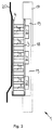
- Fig. 1 can be seen that the LEDs 2 in a matrix in several Rows and columns arranged on the cooling side 3 of the Peltier element are.
- the cooling side 3 and the heating side 4 of the Peltier element are each plate-shaped and consist of a thermally good conductive and electrically insulating material, for example Ceramics.
- a thermally good conductive and electrically insulating material for example Ceramics.
- Peltier cell 5 There are a large number between the cooling side 3 and the heating side 4 of semiconductor elements in several rows and columns side by side arranged, each forming a Peltier cell 5.
- the single ones Peltier cells 5 are each with their cold end with the LEDs 2 facing away from the cooling side 3 and with their warm end with the back of the cooling side 3 facing Heating side 4 thermally connected.
- the cooling side 3 and the heating side 4 each have their mutually facing flat sides conductor tracks, which as Power supply for the Peltier cells 5 serve.
- the Peltier element enables effective cooling of the LEDs 2, so that even at high ambient temperatures with a comparatively large continuous operating current can be supplied without to take thermal damage.
- the LEDs 2 light up even at high ambient temperatures, for example at ambient temperatures of over 80 ° Celcius with great light intensity, so that to achieve a predetermined total light intensity of the vehicle lamp only a correspondingly small number of LEDs 2 is required.
- a temperature control device is used to regulate the temperature of the light-emitting diodes 2 6 with one with the cooling side 3 of the Peltier element thermally conductively connected temperature sensor 7 is provided.
- the temperature control device 6 has a power transistor, the Peltier cells 5 with the connection 8 for the positive pole connects a DC power supply.
- the on the cooling side 3 of the Peltier element arranged temperature control device is for this via a first conductor 9 with the connection 8 for the positive pole and via a second conductor 10 and a cooling side 3 the heating side 4 connecting bridge 11 at a first power supply connection of the Peltier element connected.
- the other Power supply connection of the Peltier element is with a Terminal 12 for the negative pole of the DC power supply connected.
- the operating current is above a predetermined temperature of the Peltier element for regulating the temperature of the light-emitting diodes 2 set by means of the temperature control device 6. Below this predetermined temperature is a cooling of the LEDs 2 not required by means of the Peltier element and the Peltier element is then switched off.
- the port 8 is on the Ignition switch of the vehicle in which the vehicle lamp 1 installed, connected to the vehicle's DC power supply, such that the temperature control device 6 and the Peltier element are only activated when the vehicle ignition is switched on. At the vehicle ignition is off the circuit from the DC power supply to the Peltier element interrupted.
- LEDs 2 are not called too large Operating current is energized and thus thermally overloaded, the operating current of the LEDs 2 by means of a microprocessor 13 depending on the temperature of the cooling side 3 of the Peltier element is limited to a predetermined value.
- the Microprocessor 13 is on the one hand with a temperature sensor 14 and on the other hand with adjusting elements 15 for adjusting the LED current connected.
- a temperature sensor 14 is on the one hand with a temperature sensor 14 and on the other hand with adjusting elements 15 for adjusting the LED current connected.
- adjusting elements 15 for adjusting the LED current connected.
- everyone is LED 2 each assigned its own control element 15, the for example one connected in series with the LED 2 May have transistor.
- the microprocessor 13 is connected to a data memory 16, in which for different temperature measurements of the temperature sensor 14 each store a setpoint for the LED current is. Temperature values 14 are used to determine actual values for the temperature of the cooling side 3 of the Peltier element is detected and in read the microprocessor 13. Based on that in the data store 16 stored parameters are the actual temperature values a target value for the LED current assigned by appropriate control of the control elements 15 is set.
- the electrical circuit of the Peltier element closed, provided that the temperature at the Cooling side 3 a predetermined temperature limit, for example Can be 60 ° Celcius and due to the temperature resistance of the LEDs 2 is specified.
- the Temperature on the cooling side 3 then increases based on the Turn on the ignition switch existing starting temperature continuously until the specified temperature limit is reached becomes. Should the cooling performance of the Peltier element at high Ambient temperatures are not sufficient to open the cooling side 3 to cool down the specified temperature limit, that will Peltier element energized with the maximum operating current. At the Cooling side 3 will then face one after a while Ambient temperature lower temperature.
- the LEDs 2 become dependent energized by the respective temperature on the cooling side 3. there the LED current increases until the temperature on the cooling side 3 has reached the specified temperature limit. Below of the temperature limit, the LEDs 2 with a constant, independent of the temperature LED current operated.
- the lamp housing 17 On the cooling side 3 is a lamp housing 17 with a transparent Lens 18 arranged which the light emitting diodes 2nd covered.
- the lamp housing 17 has an inner cavity 19, in which the LEDs 2 between the cooling side 3 and the Lens 18 are arranged.
- the inner cavity 19 laterally boundary edge of the lamp housing 17 is with the cooling side 3 of the Peltier element tightly connected.
- the LEDs 2 are in the inner cavity 19 at a distance from the Housing walls of the lamp housing 17 arranged.
- the inner cavity 19 can, for example, be evacuated or, for example, with air or another thermally insulating gas.
- Fig. 3 it can be seen that the vehicle lamp 1 on the heating side 4 of the Peltier element with the sheet metal of the vehicle body Has 20 connected connection point. It can be clearly seen that the heating side 4 flat on the sheet metal of the vehicle body 20 is present. Thus, the heat given off on the heating side 3 can be Vehicle body 20 and are derived from there to the environment.
Abstract
Description
Die Erfindung betrifft eine Fahrzeugleuchte, insbesondere eine Signalleuchte, mit wenigstens einer Leuchtdiode als Lichtquelle, die mit einer Wärmeableitabrichtung thermisch leitend verbundenThe invention relates to a vehicle lamp, in particular a Signal light, with at least one light-emitting diode as light source, which are thermally conductively connected to a heat dissipation device
Eine derartige Fahrzeugleuchte ist aus EP 0 202 335 B1 bekannt. Sie weist eine Leiterplatte auf, auf deren Vorderseite eine Matrix mit einer Vielzahl von in mehreren Reihen und Spalten gruppierten Leuchtdioden angeordnet ist. An der Rückseite der Leiterplatte ist als Wärmeableiteinrichtung ein Lamellenkühlkörper angeordnet, der mit der Rückseite der Leiterplatte über einen wärmeleitenden Absorber verbunden ist. Der Lamellenkühlkörper ermöglicht zwar eine gewisse Absenkung der Betriebstemperatur der auf der Leiterplatte befindlichen Leuchtdioden, hat jedoch den Nachteil, daß die über den Kühlkörper abgeführte Wärmeleistung von der Umgebungstemperatur abhängig ist und mit zunehmender Umgebungstemperatur abnimmt. Insbesondere bei den bei Fahrzeugleuchten auftretenden hohen Betriebstemperaturen von bis zu 90° Celsius ist deshalb eine effektive Kühlung der Leuchtdioden praktisch nicht mehr möglich. Um dennoch auch bei diesen hohen Temperaturen einen Dauerbetrieb der Fahrzeugleuchte zu ermöglichen, müssen die Leuchtdioden mit einem entsprechend geringen Betriebsstrom bestromt werden, so daß die an den Leuchtdioden auftretende Verlustleistung entsprechend gering ist. Da die Lichtstärke der Leuchtdioden etwa proportional zu deren Betriebsstrom ist, ergibt sich bei Reduzierung des Betriebsstroms jedoch auch eine entsprechend geringe Lichtabgabe. So muß beispielsweise bei einer Betriebstemperatur von 80 °C der Betriebsstrom der Leuchtdioden gegenüber einer Betriebstemperatur von etwa 25 °C auf etwa die Hälfte abgesenkt werden, wodurch sich die von den Leuchtdioden abgegebene Lichtstärke ebenfalls etwa auf die Hälfte reduziert. Darüberhinaus haben Leuchtdioden aber auch noch einen negativen Temperaturkoeffizienten, d.h. ihre Lichtstärke nimmt mit zunehmender Betriebs- bzw. Sperrschichttemperatur ab. Damit die Fahrzeugleuchte auch bei hohen Umgebungstemperaturen eine geforderte Lichtstärke erreichen kann, muß deshalb die Anzahl der Leuchtdioden entsprechend groß gewählt werden. Die Fahrzeugleuchte ist deshalb noch vergleichsweise teuer.Such a vehicle lamp is known from EP 0 202 335 B1. It has a printed circuit board with a matrix on the front with a variety of grouped in multiple rows and columns LEDs is arranged. At the back of the circuit board is a finned heat sink arranged as heat dissipation device, the one with the back of the circuit board over a thermally conductive Absorber is connected. The finned heat sink allows one certain reduction in the operating temperature of the on the circuit board located LEDs, however, has the disadvantage that the over the heat dissipated heat output from the ambient temperature is dependent and with increasing ambient temperature decreases. Especially in those that occur in vehicle lights high operating temperatures of up to 90 ° Celsius is therefore one effective cooling of the LEDs is practically no longer possible. In order to operate continuously even at these high temperatures To enable the vehicle lamp, the LEDs must be used are supplied with a correspondingly low operating current, so that the power loss occurring at the light emitting diodes accordingly is low. Because the light intensity of the LEDs is roughly proportional to their operating current is obtained when the Operating current but also a correspondingly low light output. For example, at an operating temperature of 80 ° C Operating current of the LEDs compared to an operating temperature from about 25 ° C to about half, which means the luminous intensity emitted by the light-emitting diodes also increases approximately reduced by half. In addition, LEDs also have another negative temperature coefficient, i.e. their light intensity decreases with increasing operating or junction temperature. So that the vehicle light even at high ambient temperatures required luminous intensity, the number of LEDs are chosen to be large enough. The vehicle lamp is therefore still comparatively expensive.
Aus DE 197 28 763 A1 ist auch bereits eine Fahrzeugleuchte bekannt, bei der den Leuchtdioden ein PTC-Widerstand (Kaltleiter) vorgeschaltet ist, mittels dem der Betriebsstrom der Leuchtdioden bei hohen Umgebungstemperaturen abgesenkt wird. Dadurch kann zwar bei mittleren und geringen Umgebungstemperaturen eine größere Lichtstärke erreicht werden, jedoch nimmt die Lichtstärke bei höheren Umgebungstemperaturen etwa proportional zur Absenkung des Betriebsstroms der Leuchtdioden ab. Nachteilig ist außerdem, daß sich beim Verändern des Betriebsstroms der Leuchtdiode auch deren Leuchtfarbe ändert, was besonders bei Signalleuchten problematisch ist, bei denen die Wellenlänge des ausgesendeten Lichts aufgrund gesetzlicher Bestimmungen in einem fest vorgegebenen Spektralbereich liegen muß. Ungünstig ist außerdem, daß die in dem PTC-Widerstand umgesetzte Verlustleistung ebenfalls zur Erwärmung der Fahrzeugleuchte beiträgt.A vehicle lamp is also known from DE 197 28 763 A1, where the light-emitting diodes are preceded by a PTC resistor (PTC thermistor) is, by means of which the operating current of the LEDs high ambient temperatures. This may cause medium and low ambient temperatures a greater light intensity can be achieved, however, the light intensity decreases at higher ones Ambient temperatures roughly proportional to the lowering of the Operating current of the LEDs. Another disadvantage is that change when changing the operating current of the LED Luminous color changes, which is particularly problematic with signal lights at which the wavelength of the emitted light is due statutory provisions in a fixed spectral range must lie. It is also disadvantageous that those in the PTC resistor implemented power loss also for heating the vehicle lamp contributes.
Es besteht deshalb die Aufgabe, eine Fahrzeugleuchte der eingangs genannten Art zu schaffen, die auch bei hohen Umgebungstemperaturen eine ausreichend große Lichtstärke der Leuchtdiode(n) ermöglicht.There is therefore the task of a vehicle lamp at the beginning to create the type mentioned, even at high ambient temperatures A sufficiently large light intensity of the LED (s) enables.
Die Lösung dieser Aufgabe besteht darin, daß die Wärmeableiteinrichtung zur Kühlung der Leuchtdiode(n) als aktive Temperiereinrichtung ausgebildet ist.The solution to this problem is that the heat dissipation device for cooling the light-emitting diode (s) as an active temperature control device is trained.
Die Leuchtdioden können dann auch bei hohen Umgebungstemperaturen wirkungsvoll gekühlt werden, wobei sogar eine Kühlung der Leuchtdioden bis auf eine Betriebstemperatur möglich ist, die kleiner ist als die Umgebungstemperatur. In vorteilhafter Weise können deshalb die Leuchtdioden auch bei hohen Umgebungstemperaturen, beispielsweise bei Temperaturen über 80 °C, mit einem vergleichsweise hohen Dauerbetriebsstrom bestromt werden, so daß sie eine entsprechend hohe Lichtstärke abgeben. Die Anzahl der Leuchtdioden kann somit bei gleicher Lichtstärke gegenüber einer konventionellen Fahrzeugleuchte mit passivem Kühlkörper erheblich reduziert sein, d.h. es können Leuchtdioden eingespart werden. Die erfindungsgemäße Fahrzeugleuchte ist deshalb kostengünstig herstellbar. Gegenüber einer konventionellen Fahrzeugleuchte mit passivem Kühlkörper kann außerdem die Absenkung des Betriebsstromes der Leuchtdioden bei hohen Umgebungstemperaturen reduziert und/oder zu höheren Temperaturen verschoben sein oder sogar ganz entfallen. Die Fahrzeugleuchte weist deshalb eine weitestgehend von der Umgebungstemperatur unabhängige, konstante Leuchtfarbe auf. In vorteilhafter Weise ergibt sich aufgrund der durch die aktive Temperiereinrichtung reduzierte Betriebstemperatur der Leuchtdioden aber auch eine längere Lebensdauer der Leuchtdioden und somit der gesamten Fahrzeugleuchte.The LEDs can then operate even at high ambient temperatures be cooled effectively, even cooling the LEDs are possible up to an operating temperature that is lower is than the ambient temperature. Can advantageously therefore the LEDs even at high ambient temperatures, for example at temperatures above 80 ° C, with a comparative high continuous operating current are supplied with current, so that they are a emit a correspondingly high light intensity. The number of LEDs can thus with the same light intensity compared to a conventional Vehicle light with passive heat sink significantly reduced be, i.e. LEDs can be saved. The invention Vehicle lights are therefore inexpensive to manufacture. Compared to a conventional vehicle lamp with passive Heatsink can also lower the operating current LEDs reduced and / or at high ambient temperatures be shifted to higher temperatures or even be dropped entirely. The vehicle lamp therefore has a largely from the Ambient temperature independent, constant light color. In advantageously results from the active Temperature control device reduced operating temperature of the LEDs but also a longer life of the LEDs and thus the entire vehicle light.
Besonders vorteilhaft ist, wenn die Temperiereinrichtung wenigstens ein Peltierelement mit einer Kühlseite und einer Heizseite aufweist, und wenn die Leuchtdiode(n) mit der Kühlseite des Peltierelements thermisch leitend verbunden ist (sind). Dadurch ergibt sich eine einfach aufgebaute, kompakte Temperiereinrichtung, die außerdem kostengünstig herstellbar ist. Gegebenenfalls können sogar mehrere Peltierelemente zu einem Stapel miteinander verbunden sein, wodurch eine noch effektivere Kühlung der Leuchtdiode(n) erreicht werden kann. Dabei ist jeweils bei zwei benachbart übereinander geschichteten Peltierelementen die Kühlseite des einen Peltierelements mit der Wärmeseite des anderen, dazu benachbarten Peltierelements verbunden.It is particularly advantageous if the temperature control device at least one Peltier element with a cooling side and a heating side and if the LED (s) with the cooling side of the Peltier element is (are) thermally conductively connected. Thereby the result is a simple, compact temperature control device, which is also inexpensive to manufacture. If necessary, you can even several Peltier elements connected together in a stack be, whereby an even more effective cooling of the LED (s) can be achieved. Two are adjacent stacked Peltier elements the cooling side of one Peltier element with the heat side of the other, adjacent to it Peltier element connected.
Vorteilhaft ist, wenn die Temperiereinrichtung zur Regelung der Temperatur der Leuchtdiode(n) eine Temperatur-Regeleinrichtung mit einem Temperaturfühler aufweist. Die Betriebstemperatur der Leuchtdioden kann dann weitgehend unabhängig von der Umgebungstemperatur konstantgehalten oder auf eine vorgegebene Temperatur begrenzt werden. Bei niedrigen Umgebungstemperaturen kann die Temperiereinrichtung gegebenenfalls ganz abgeschaltet sein, wodurch bei einer ein Peltierelement aufweisenden Temperiereinrichtung die elektrische Energie zum Betreiben des Peltierelements eingespart werden kann.It is advantageous if the temperature control device for regulating the Temperature of the LED (s) with a temperature control device has a temperature sensor. The operating temperature of the LEDs can then largely independent of the ambient temperature kept constant or at a predetermined temperature be limited. At low ambient temperatures, the Temperature control device may be completely switched off, whereby in a tempering device having a Peltier element the electrical energy for operating the Peltier element is saved can be.
Bei einer Ausführungsform der Erfindung ist (sind) die Leuchtdiode(n) mit einer Stromversorgungseinrichtung verbunden, die einen an einem Temperatursensor angeschlossenen Stromsteuereingang zum temperaturabhängigen Einstellen des Leuchtdioden-Betriebsstromes aufweist. Der Betriebsstrom kann dann oberhalb einer kritischen Temperatur abgesenkt werden. Die Fahrzeugleuchte kann dadurch bei noch höheren Umgebungstemperaturen im Dauerbetrieb betrieben werden, ohne daß die Leuchtdiode(n) thermisch geschädigt wird (werden). Außerdem werden die Leuchtdioden unmittelbar nach dem Einschalten des Peltierelements vor thermischer Überlastung geschützt, wenn die Kühlseite des Peltierelements ihre Betriebstemperatur noch nicht erreicht hat.In one embodiment of the invention, the light-emitting diode (s) connected to a power supply device that one a current control input connected to a temperature sensor temperature-dependent setting of the LED operating current having. The operating current can then be above a critical Temperature can be lowered. The vehicle lamp can thereby operated even higher ambient temperatures in continuous operation be without the LED (s) being thermally damaged (become). In addition, the LEDs are immediately after the Switching on the Peltier element before thermal overload protected when the cooling side of the Peltier element reaches its operating temperature has not yet reached.
Vorteilhaft ist, wenn der Stromsteuereingang der Stromversorgungseinrichtung indirekt über einen Mikroprozessor mit dem Temperatursensor verbunden ist und wenn dem Mikroprozessor ein Datenspeicher zugeordnet ist, in welchem für unterschiedliche Temperaturmeßwerte des Temperatursensors jeweils ein Sollwert für den Leuchtdiodenstrom gespeichert ist. Dabei können die Temperaturmeßwerte und die diesem jeweils zugeordneten Leuchtdiodenströme beispielsweise in Form von Wertekombinationen oder in Form von Kennlinien in dem Datenspeicher abgelegt sein. Gegebenenfalls können für die einzelnen Leuchtdiodenstrom-Sollwerte jeweils sogar mehrere, ein zeitliches Temperaturprofil definierende Temperaturwerte gespeichert sein, so daß bei der Einstellung des Leuchtdiodenstromes eine zeitliche Veränderung der Temperatur der Leuchtdioden und/oder der Umgebung berücksichtigt werden kann. Die temperaturabhängige Einstellung des Leuchtdiodenstromes kann beispielsweise mittels eines mit einem Ausgang des Mikroprozessors verbundenen Transistors erfolgen.It is advantageous if the current control input of the power supply device indirectly via a microprocessor with the temperature sensor is connected and if the microprocessor has a data memory is assigned in which for different temperature measurements of the temperature sensor a setpoint for the LED current is saved. The temperature readings can and the light-emitting diode currents associated with this, for example in the form of value combinations or in the form of characteristic curves in the Data storage must be stored. If necessary, for the individual LED current setpoints even several temperature values defining the temporal temperature profile are stored be so that when setting the LED current a temporal change in the temperature of the LEDs and / or Environment can be taken into account. The temperature dependent Adjustment of the light emitting diode current can be done, for example a transistor connected to an output of the microprocessor respectively.
Vorteilhaft ist, wenn mehrere jeweils als Halbleiterchip ausgebildeten Leuchtdioden in Hybridtechnik mit der Kühlseite des Peltierelements und/oder einer damit in wärmeleitenden Kontakt stehenden Leiterplatten verbunden sind. Die Fahrzeugleuchte ist dann besonders kostengünstig herstellbar. Dabei können gegebenenfalls noch weitere für den Betrieb oder die Ansteuerung der Leuchtdioden vorgesehene Schaltungsteile, wie zum Beispiel der Mikroprozessor, der Datenspeicher, wenigstens ein Leistungstransistor zur Einstellung des Leuchtdiodenstromes und/oder wenigstens ein Temperaturfühler in Hybridtechnik mit der Leiterplatte oder der Kühlseite des Peltierelements integriert sein.It is advantageous if several are each designed as semiconductor chips Hybrid LEDs with the cooling side of the Peltier element and / or a thermally conductive contact therewith standing circuit boards are connected. The vehicle lamp is then particularly inexpensive to manufacture. Here, if necessary even more for the operation or control of the LEDs provided circuit parts, such as the microprocessor, the data memory, at least one power transistor for adjustment of the LED current and / or at least one temperature sensor in hybrid technology with the circuit board or the cooling side of the Peltier element can be integrated.
Zweckmäßigerweise liegen die als Halbleiterchip ausgebildeten Leuchtdioden jeweils mit ihrer der Abstrahlseiten abgewandten Rückseite vorzugsweise plan an der Kühlseite des Peltierelements oder an der dem Peltierelement abgewandten Vorderseite einer rückseitig mit dem Peltierelement wärmeleitend verbundenen Leiterplatte an. Die Leuchtdioden können dann großflächig und somit besonders wirkungsvoll gekühlt werden.The semiconductor chips are expediently located LEDs each with their facing away from the emission sides Back preferably flat on the cooling side of the Peltier element or on the front of a Peltier element facing away from one connected on the back to the Peltier element in a heat-conducting manner Circuit board. The light emitting diodes can then cover a large area and thus be cooled particularly effectively.
Besonders vorteilhaft ist, wenn eine die Kühlseite und die Heizseite des Peltiertelements gegeneinander abgrenzende, thermische Isolation vorgesehen ist und wenn diese vorzugsweise durch ein die Kühlseite mit den Leuchtdioden umgrenzendes Leuchtengehäuse gebildet ist. Die Leuchtdioden sind dann im inneren des Leuchtengehäuses thermisch mit der Kühlseite des Peltierelements verbunden und durch die Wandung des Leuchtengehäuses gegen die Wärmeseite des Peltierelements thermisch isoliert. Die an den Leuchtdioden auftretende Verlustwärme kann dann noch besser von den Leuchtdioden abgeführt werden. Die den Leuchtdioden zugewandte Wandung des Leuchtengehäuses kann eine Lichtscheibe und/oder optische Elemente, wie zum Beispiel Streulinsen, aufweisen.It is particularly advantageous if the cooling side and the Thermal side of the Pelt quarter element delimiting each other Isolation is provided and if this is preferably by a Cooling side with luminaire housing bordering the light-emitting diodes is. The LEDs are then inside the luminaire housing thermally connected to the cooling side of the Peltier element and through the wall of the lamp housing against the heat side of the Peltier element thermally insulated. The on the LEDs Loss of heat that occurs can then be better from the LEDs be dissipated. The wall of the Luminaire housing can be a lens and / or optical Have elements such as diffusing lenses.
Vorteilhaft ist, wenn die Fahrzeugleuchte Anschlußstellen zum thermisch leitenden Verbinden der Heizseite des Peltierelements mit einer Fahrzeugkarosserie aufweist. Die an der Heizseite des Peltierelements abgegebene Wärme kann dann in ein thermisch gut leitendes Teil der Fahrzeugkarosserie, beispielsweise ein Blechteil abgeleitet werden. Die Außenkontur der Fahrzeugleuchte kann an der Verbindungsstelle an die Fahrzeugkarosserie formangepaßt sein, um eine großflächige Wärmeeinleitung in die Fahrzeugkarosserie zu ermöglichen.It is advantageous if the vehicle light connection points to thermally conductive connection of the heating side of the Peltier element having a vehicle body. The on the heating side of the Peltier element emitted heat can then be thermally good conductive part of the vehicle body, for example a sheet metal part be derived. The outer contour of the vehicle lamp can on the Connection point to the vehicle body to be adapted to extensive heat transfer into the vehicle body enable.
Nachfolgend ist ein Ausführungsbeispiel der Erfindung anhand der Zeichnung näher erläuert. Es zeigen zum Teil stärker schematisiert:
- Fig. 1
- eine Aufsicht auf die Kühlseite eines Peltierelements einer Fahrzeugleuchte, wobei die an der Kühlseite matrixförmig angeordneten Leuchtdioden besonders gut erkennbar sind, und wobei das Layout der Leiterbahnen vereinfacht dargestellt ist
- Fig. 2
- eine Seitenansicht der in Fig. 1 gezeigten Fahrzeugleuchte und
- Fig. 3
- einen Querschnitt durch die an einer Fahrzeugkarosserie montierte Fahrzeugleuchte gemäß Fig. 1, wobei die Fahrzeugkarosserie nur teilweise dargestellt ist.
- Fig. 1
- a top view of the cooling side of a Peltier element of a vehicle lamp, the light-emitting diodes arranged in a matrix on the cooling side being particularly well recognizable, and the layout of the conductor tracks being shown in simplified form
- Fig. 2
- a side view of the vehicle lamp shown in Fig. 1 and
- Fig. 3
- a cross section through the vehicle lamp mounted on a vehicle body according to FIG. 1, the vehicle body being shown only partially.
Eine im ganzen mit 1 bezeichnete Fahrzeugleuchte weist als
Lichtquellen mehrere Leuchtdioden 2 auf, die jeweils mit der
Kühlseite 3 eines eine Kühlseite 3 und einer Heizseite 4
aufweisenden Peltierelement thermisch leitend verbunden sind. In
Fig. 1 ist erkennbar, daß die Leuchtdioden 2 matrixförmig in mehreren
Reihen und Spalten an der Kühlseite 3 des Peltierelements angeordnet
sind.A vehicle lamp designated as a whole has 1 as
Light sources several
Die Kühlseite 3 und die Heizseite 4 des Peltierelements sind jeweils
plattenförmig ausgebildet und bestehen aus einem thermisch gut
leitenden und elektrisch isolierenden Material, zum Beispiel aus
Keramik. In Fig. 2 ist erkennbar, daß die Kühlseite 3 und die
Heizseite 4 etwa parallel zueinander angeordnet sind.The
Zwischen der Kühlseite 3 und der Heizseite 4 sind eine Vielzahl
von Halbleiterelementen in mehreren Reihen und Spalten nebeneinander
angeordnet, die jeweils eine Peltierzelle 5 bilden. Die einzelnen
Peltierzellen 5 sind jeweils mit ihrem kalten Ende mit der den
Leuchtdioden 2 abgewandten Rückseite der Kühlseite 3 und mit ihrem
warmen Ende mit der der Kühlseite 3 zugewandten Rückseite der
Heizseite 4 thermisch leitend verbunden.There are a large number between the cooling
Die Kühlseite 3 und die Heizseite 4 weisen jeweils an ihren
einander zugewandten Flachseiten Leiterbahnen auf, die als
Stromzufuhr für die Peltierzellen 5 dienen. Das Peltierelement
ermöglicht eine wirkungsvolle Kühlung der Leuchtdioden 2, so daß
diese auch bei hohen Umgebungstemperaturen mit einem vergleichsweise
großen Dauer-Betriebsstrom bestromt werden können, ohne
thermisch Schaden zu nehmen. Die Leuchtdioden 2 leuchten dadurch
auch bei hohen Umgebungstemperaturen, beispielsweise bei Umgebungstemperaturen
von über 80° Celcius mit großer Lichtstärke, so daß
zum Erreichen einer vorgegebenen Gesamtlichtstärke der Fahrzeugleuchte
nur eine entsprechend kleine Anzahl Leuchtdioden 2
erforderlich ist.The
Zur Regelung der Temperatur der Leuchtdioden 2 ist eine Temperatur-Regeleinrichtung
6 mit einem mit der Kühlseite 3 des Peltierelements
thermisch leitend verbundene Temperaturfühler 7 vorgesehen.
Die Temperatur-Regeleinrichtung 6 hat einen Leistungstransistor,
der die Peltierzellen 5 mit dem Anschluß 8 für den positiven Pol
einer Gleichstromversorgung verbindet. Die an der Kühlseite 3 des
Peltierelements angeordnete Temperatur-Regeleinrichtung ist dazu
über eine erste Leiterbahn 9 mit dem Anschluß 8 für den Pluspol
und über eine zweite Leiterbahn 10 sowie eine die Kühlseite 3 mit
der Heizseite 4 verbindende Brücke 11 an einem ersten Stromversorgungsanschluß
des Peltierelements angeschlossen. Der andere
Stromversorgungsanschluß des Peltierelements ist mit einem
Anschluß 12 für den negativen Pol der Gleichstromversorgung
verbunden.A temperature control device is used to regulate the temperature of the light-emitting
Oberhalb einer vorgegebenen Temperatur wird der Betriebsstrom
des Peltierelements zum Regeln der Temperatur der Leuchtdioden 2
mittels der Temperatur-Regeleinrichtung 6 eingestellt. Unterhalb
dieser vorgegebenen Temperatur ist eine Kühlung der Leuchtdioden
2 mittels des Peltierelements nicht erforderlich und das Peltierelement
ist dann abgeschaltet. Der Anschluß 8 ist über den
Zündschalter des Fahrzeugs, in welches die Fahrzeugleuchte 1
eingebaut ist, mit der Gleichstromversorgung des Fahrzeugs verbunden,
derart, daß die Temperatur-Regeleinrichtung 6 und das Peltierelement
nur bei eingeschalteter Fahrzeugzündung aktiviert sind. Bei
abgeschalteter Fahrzeugzündung ist der Stromkreis von der
Gleichstromversorgung zum Peltierelement unterbrochen.The operating current is above a predetermined temperature
of the Peltier element for regulating the temperature of the light-emitting
Damit insbesondere nach dem Einschalten der Zündung beziehungsweise
der Stromversorgung des Fahrzeugs die bei hohen Umgebungstemperaturen
zunächst noch heißen Leuchtdioden 2 nicht mit einem zu großen
Betriebsstrom bestromt und somit thermisch überlastet werden,
wird der Betriebsstrom der Leuchtdioden 2 mittels eines Mikroprozessors
13 in Abhängigkeit von der Temperatur der Kühlseite 3
des Peltierelements auf einen vorgegebenen Wert begrenzt. Der
Mikroprozessor 13 ist dazu einerseits mit einem Temperatursensor
14 und andererseits mit Stellelementen 15 zum Einstellen des
Leuchtdiodenstroms verbunden. Wie in Fig. 1 erkennbar ist, ist jeder
Leuchtdiode 2 jeweils ein eigenes Stellelement 15 zugeordnet, das
beispielsweise einen mit der Leuchtdiode 2 in Reihe geschalteten
Transistor aufweisen kann.So especially after switching on the ignition respectively
the vehicle's power supply at high ambient temperatures
Initially,
Der Mikroprozessor 13 ist mit einem Datenspeicher 16 verbunden,
in welchem für unterschiedliche Temperaturmeßwerte des Temperatursensors
14 jeweils ein Sollwert für den Leuchtdiodenstrom gespeichert
ist. Mittels des Temperatursensors 14 werden jeweils Ist-Werte für
die Temperatur der Kühlseite 3 des Peltierelements erfaßt und in
den Mikroprozessor 13 eingelesen. Anhand der in dem Datenspeicher
16 abgelegten Kenngrößen wird den Temperatur-Ist-Werten jeweils
ein Soll-Wert für den Leuchtdiodenstrom zugeordnet, der durch
entsprechendes Ansteuern der Stellelemente 15 eingestellt wird.The
Beim Einschalten des Zündschalters des Fahrzeugs wird der Stromkreis
des Peltierelements geschlossen, sofern die Temperatur an der
Kühlseite 3 einen vorgegebenen Temperatur-Grenzwert, der beispielsweise
60° Celcius betragen kann und durch die Temperaturbelastbarkeit
der Leuchtdioden 2 vorgegeben ist, überschreitet. Die
Temperatur an der Kühlseite 3 nimmt dann ausgehend von der beim
Einschalten des Zündschalters vorhandenen Anfangstemperatur
kontinuierlich ab, bis der vorgegebene Temperaturgrenzwert erreicht
wird. Sollte die Kühlleistung des Peltierelements bei hohen
Umgebungstemperaturen nicht ausreichen, um die Kühlseite 3 auf
dem vorgegebenen Temperatur-Grenzwert abzukühlen, wird das
Peltierelement mit dem maximalen Betriebsstrom bestromt. An der
Kühlseite 3 stellt sich dann nach einiger Zeit eine gegenüber der
Umgebungstemperatur geringere Temperatur ein. When the vehicle's ignition switch is turned on, the electrical circuit
of the Peltier element closed, provided that the temperature at the
Cooling side 3 a predetermined temperature limit, for example
Can be 60 ° Celcius and due to the temperature resistance
of the
Während der Abkühlphase werden die Leuchtdioden 2 in Abhängigkeit
von der jeweiligen Temperatur an der Kühlseite 3 bestromt. Dabei
nimmt der Leuchtdiodenstrom zu, bis die Temperatur an der Kühlseite
3 den vorgegebenen Temperaturgrenzwert erreicht hat. Unterhalb
des Temperatur-Grenzwerts werden die Leuchtdioden 2 mit einem
konstanten, von der Temperatur unabhängigen Leuchtdiodenstrom
betrieben.During the cooling phase, the
In Fig. 1 und 3 ist erkennbar, daß an der Kühlseite 3 des
Peltierelements eine Vielzahl von Leuchtdioden 2 matrixförmig
nebeneinander angeordnet sind. Die Leuchtdioden 2 sind als SMD-Bauteile
ausgebildet, die jeweils an ihrer der Abstrahlseite
abgewandten Rückseite plan an der Oberfläche der Kühlseite
3 anliegen. Dadurch ergibt sich eine großflächige, thermisch
gut leitende Verbindung zwischen den Leuchtdioden 2 und der
Kühlseite 3. Erwähnt werden soll nach, daß die in Hybridtechnik
ausgebildete Kühlseite 3 weitere, in der Zeichnung nicht dargestellte
Bauelemente aufweisen kann.1 and 3 it can be seen that on the
An der Kühlseite 3 ist ein Leuchtengehäuse 17 mit einer transparenten
Lichtscheibe 18 angeordnet, welche die Leuchtdioden 2
überdeckt. Das Leuchtengehäuse 17 weist eine Innenhöhlung 19 auf,
in der die Leuchtdioden 2 zwischen der Kühlseite 3 und der
Lichtscheibe 18 angeordnet sind. Der die Innenhöhlung 19 seitlich
umgrenzende Rand des Leuchtengehäuses 17 ist mit der Kühlseite 3
des Peltierelements dicht verbunden. Durch das Leuchtengehäuse 17
ist die die Leuchtdioden 2 aufweisende Vorderseite der Kühlseite
3 des Peltierelements thermisch gegen dessen Heizseite 4 isoliert.
Die Leuchtdioden 2 sind in der Innenhöhlung 19 mit Abstand zu den
Gehäusewänden des Leuchtengehäuses 17 angeordnet. Die Innenhöhlung
19 kann beispielsweise evakuiert oder zum Beispiel mit Luft
oder einem anderen thermisch isolierenden Gas gefüllt sein.On the
In Fig. 3 ist erkennbar, daß die Fahrzeugleuchte 1 an der Heizseite
4 des Peltierelements eine mit dem Blech der Fahrzeugkarosserie
20 verbundene Anschlußstelle aufweist. Deutlich ist erkennbar, daß
die Heizseite 4 plan an dem Blech der Fahrzeugkarosserie 20
anliegt. Somit kann die an der Heizseite 3 abgegebene Wärme in die
Fahrzeugkarosserie 20 und von dort an die Umgebung abgeleitet werden.In Fig. 3 it can be seen that the
Claims (10)
Applications Claiming Priority (2)
| Application Number | Priority Date | Filing Date | Title |
|---|---|---|---|
| DE19932051A DE19932051A1 (en) | 1999-07-09 | 1999-07-09 | Vehicle light |
| DE19932051 | 1999-07-09 |
Publications (2)
| Publication Number | Publication Date |
|---|---|
| EP1067332A2 true EP1067332A2 (en) | 2001-01-10 |
| EP1067332A3 EP1067332A3 (en) | 2001-10-10 |
Family
ID=7914218
Family Applications (1)
| Application Number | Title | Priority Date | Filing Date |
|---|---|---|---|
| EP00114364A Withdrawn EP1067332A3 (en) | 1999-07-09 | 2000-07-05 | Vehicle lamp |
Country Status (2)
| Country | Link |
|---|---|
| EP (1) | EP1067332A3 (en) |
| DE (1) | DE19932051A1 (en) |
Cited By (13)
| Publication number | Priority date | Publication date | Assignee | Title |
|---|---|---|---|---|
| EP1408476A1 (en) * | 2002-10-10 | 2004-04-14 | Barco N.V. | Light emission display arrangements |
| EP1408475A1 (en) * | 2002-10-11 | 2004-04-14 | Barco N.V. | Light emission display arrangements |
| WO2004038290A1 (en) * | 2002-10-28 | 2004-05-06 | Dialight Corporation | Led illuminated lamp with thermoelectric heat management |
| WO2005062089A1 (en) * | 2003-12-02 | 2005-07-07 | 3M Innovative Properties Company | Solid state light device |
| WO2006033998A1 (en) * | 2004-09-16 | 2006-03-30 | Magna International Inc. | Thermal management system for solid state automotive lighting |
| WO2006066532A1 (en) * | 2004-12-22 | 2006-06-29 | Patent-Treuhand- Gesellschaft Für Elektrische Glühlampen Mbh | Lighting device comprising at least one light-emitting diode and vehicle headlight |
| US7157838B2 (en) | 2002-10-10 | 2007-01-02 | Barco N.V. | Light emission display arrangements |
| US7163327B2 (en) | 2002-12-02 | 2007-01-16 | 3M Innovative Properties Company | Illumination system using a plurality of light sources |
| US7189983B2 (en) | 2003-12-02 | 2007-03-13 | 3M Innovative Properties Company | LED modifying apparatus and method |
| WO2009024134A1 (en) * | 2007-08-20 | 2009-02-26 | Schmidt & Haensch Gmbh & Co. | Method and device for the exact and controlled effective wavelength adjustment of the emitted radiation of a light-emitting diode |
| EP2483920A2 (en) * | 2009-09-28 | 2012-08-08 | Dialight Corporation | Apparatus for using heat pipes in controlling temperature of an led light unit |
| US8240885B2 (en) | 2008-11-18 | 2012-08-14 | Abl Ip Holding Llc | Thermal management of LED lighting systems |
| DE102004047685B4 (en) * | 2004-09-30 | 2015-09-24 | Volkswagen Ag | Method for controlling a vehicle light source and control unit for a vehicle light source |
Families Citing this family (10)
| Publication number | Priority date | Publication date | Assignee | Title |
|---|---|---|---|---|
| DE10130809A1 (en) * | 2001-06-26 | 2003-01-02 | Hella Kg Hueck & Co | Headlights for vehicles |
| CA2480390A1 (en) * | 2002-03-26 | 2003-10-02 | Enfis Limited | Cooled light emitting apparatus |
| DE10313246A1 (en) * | 2003-03-25 | 2004-10-21 | Sitronic Gesellschaft für elektrotechnische Ausrüstung mbH. & Co. KG | Automotive lamp module |
| DE10319363A1 (en) * | 2003-04-29 | 2004-11-18 | Volkswagen Ag | Car headlamp etc. with control of dew protection device and housing in which dew protection device contains Peltier element, forming cooling surface in housing |
| DE102004013680A1 (en) * | 2004-03-18 | 2005-10-20 | Siemens Ag | Light source for imaging unit |
| DE102004025624A1 (en) * | 2004-05-25 | 2005-12-15 | Hella Kgaa Hueck & Co. | Headlamp with heat exchanger for cooling bulbs |
| DE102004025623A1 (en) * | 2004-05-25 | 2005-12-15 | Hella Kgaa Hueck & Co. | Headlight for a motor vehicle |
| DE102004028987A1 (en) * | 2004-06-16 | 2006-01-05 | Volkswagen Ag | Illumination unit controlling method for motor vehicle, involves increasing or decreasing duty cycle of pulse width modulation when ambient temperature increases or decreases, for adjusting light emission within maximum and minimum values |
| DE102009019272B4 (en) * | 2009-04-28 | 2012-02-16 | Imm Photonics Gmbh | Temperature-stabilized collimator light source |
| DE102017124455A1 (en) | 2017-10-19 | 2019-04-25 | Osram Opto Semiconductors Gmbh | Optoelectronic component with an effect element |
Citations (2)
| Publication number | Priority date | Publication date | Assignee | Title |
|---|---|---|---|---|
| EP0202335B1 (en) | 1984-11-15 | 1989-10-25 | Japan Traffic Management Technology Association | Signal light unit having heat dissipating function |
| DE19728763A1 (en) | 1997-07-07 | 1999-01-14 | Reitter & Schefenacker Gmbh | Circuit device for protecting current-operated lamps, in particular LEDs, for signal or lighting purposes |
Family Cites Families (9)
| Publication number | Priority date | Publication date | Assignee | Title |
|---|---|---|---|---|
| US3309565A (en) * | 1959-12-14 | 1967-03-14 | Mc Graw Edison Co | Light output of fluorescent lamps automatically held constant by means of peltier type coolers |
| US5156999A (en) * | 1990-06-08 | 1992-10-20 | Wai-Hon Lee | Packaging method for semiconductor laser/detector devices |
| US5528474A (en) * | 1994-07-18 | 1996-06-18 | Grote Industries, Inc. | Led array vehicle lamp |
| DE19528459C2 (en) * | 1995-08-03 | 2001-08-23 | Garufo Gmbh | Cooling for a light unit equipped with LEDs |
| US5612593A (en) * | 1995-08-30 | 1997-03-18 | Rockwell International | Fluorescent tube thermal management system utilizing thermal electric cooler units |
| US5936353A (en) * | 1996-04-03 | 1999-08-10 | Pressco Technology Inc. | High-density solid-state lighting array for machine vision applications |
| US5890794A (en) * | 1996-04-03 | 1999-04-06 | Abtahi; Homayoon | Lighting units |
| JP3180701B2 (en) * | 1997-02-07 | 2001-06-25 | 日本電気株式会社 | Semiconductor laser device |
| EP1140626B1 (en) * | 1998-12-21 | 2003-03-05 | AlliedSignal Inc. | Ir diode based high intensity light |
-
1999
- 1999-07-09 DE DE19932051A patent/DE19932051A1/en not_active Withdrawn
-
2000
- 2000-07-05 EP EP00114364A patent/EP1067332A3/en not_active Withdrawn
Patent Citations (2)
| Publication number | Priority date | Publication date | Assignee | Title |
|---|---|---|---|---|
| EP0202335B1 (en) | 1984-11-15 | 1989-10-25 | Japan Traffic Management Technology Association | Signal light unit having heat dissipating function |
| DE19728763A1 (en) | 1997-07-07 | 1999-01-14 | Reitter & Schefenacker Gmbh | Circuit device for protecting current-operated lamps, in particular LEDs, for signal or lighting purposes |
Cited By (21)
| Publication number | Priority date | Publication date | Assignee | Title |
|---|---|---|---|---|
| US7157838B2 (en) | 2002-10-10 | 2007-01-02 | Barco N.V. | Light emission display arrangements |
| EP1408476A1 (en) * | 2002-10-10 | 2004-04-14 | Barco N.V. | Light emission display arrangements |
| EP1408475A1 (en) * | 2002-10-11 | 2004-04-14 | Barco N.V. | Light emission display arrangements |
| WO2004038290A1 (en) * | 2002-10-28 | 2004-05-06 | Dialight Corporation | Led illuminated lamp with thermoelectric heat management |
| US7510303B2 (en) | 2002-10-28 | 2009-03-31 | Dialight Corporation | LED illuminated lamp with thermoelectric heat management |
| US7163327B2 (en) | 2002-12-02 | 2007-01-16 | 3M Innovative Properties Company | Illumination system using a plurality of light sources |
| WO2005062089A1 (en) * | 2003-12-02 | 2005-07-07 | 3M Innovative Properties Company | Solid state light device |
| US7189983B2 (en) | 2003-12-02 | 2007-03-13 | 3M Innovative Properties Company | LED modifying apparatus and method |
| US7202490B2 (en) | 2003-12-02 | 2007-04-10 | 3M Innovative Properties Company | LED modifying apparatus and method |
| US7202489B2 (en) | 2003-12-02 | 2007-04-10 | 3M Innovative Properties Company | LED modifying apparatus and method |
| US7250611B2 (en) | 2003-12-02 | 2007-07-31 | 3M Innovative Properties Company | LED curing apparatus and method |
| WO2006033998A1 (en) * | 2004-09-16 | 2006-03-30 | Magna International Inc. | Thermal management system for solid state automotive lighting |
| US7575354B2 (en) | 2004-09-16 | 2009-08-18 | Magna International Inc. | Thermal management system for solid state automotive lighting |
| DE102004047685B4 (en) * | 2004-09-30 | 2015-09-24 | Volkswagen Ag | Method for controlling a vehicle light source and control unit for a vehicle light source |
| WO2006066532A1 (en) * | 2004-12-22 | 2006-06-29 | Patent-Treuhand- Gesellschaft Für Elektrische Glühlampen Mbh | Lighting device comprising at least one light-emitting diode and vehicle headlight |
| US9578716B2 (en) | 2006-06-30 | 2017-02-21 | Dialight Corporation | Apparatus for using heat pipes in controlling temperature of an LED light unit |
| WO2009024134A1 (en) * | 2007-08-20 | 2009-02-26 | Schmidt & Haensch Gmbh & Co. | Method and device for the exact and controlled effective wavelength adjustment of the emitted radiation of a light-emitting diode |
| US8240885B2 (en) | 2008-11-18 | 2012-08-14 | Abl Ip Holding Llc | Thermal management of LED lighting systems |
| EP2483920A2 (en) * | 2009-09-28 | 2012-08-08 | Dialight Corporation | Apparatus for using heat pipes in controlling temperature of an led light unit |
| EP2483920A4 (en) * | 2009-09-28 | 2014-01-22 | Dialight Corp | Apparatus for using heat pipes in controlling temperature of an led light unit |
| AU2010298662B2 (en) * | 2009-09-28 | 2015-07-09 | Dialight Corporation | Apparatus for using heat pipes in controlling temperature of an LED light unit |
Also Published As
| Publication number | Publication date |
|---|---|
| EP1067332A3 (en) | 2001-10-10 |
| DE19932051A1 (en) | 2001-01-11 |
Similar Documents
| Publication | Publication Date | Title |
|---|---|---|
| EP1067332A2 (en) | Vehicle lamp | |
| EP0662209B1 (en) | Thermoelectric heating or cooling device | |
| DE2737345C2 (en) | Semiconductor laser device with a Peltier element | |
| DE102010030639B4 (en) | Lighting device with movable converter element | |
| EP1771891B1 (en) | Light emitting component and illumination module | |
| EP1995514B1 (en) | Lighting unit | |
| DE60305060T2 (en) | LED LAMP WITH THERMOELECTRIC HEAT CONTROL | |
| DE19528459C2 (en) | Cooling for a light unit equipped with LEDs | |
| DE10110835B4 (en) | Lighting arrangement with a plurality of LED modules on a heat sink surface | |
| EP3167224B1 (en) | Semiconductor lamp | |
| DE102004060890A1 (en) | Motor vehicle headlight element | |
| EP1777755A1 (en) | Light-emitting element with at least one light-emitting crystal | |
| DE102011006725A1 (en) | headlamp unit | |
| DE102005018175A1 (en) | LED module and LED lighting device with several LED modules | |
| EP1792117A1 (en) | Vehicle headlight | |
| DE102014222701A1 (en) | Ultraviolet irradiation head and ultraviolet irradiation device | |
| DE102015118984B4 (en) | light source | |
| WO2009121330A2 (en) | Illumination device | |
| DE19957452A1 (en) | Electrical additional heat exchanger for motor vehicles has positive temperature coefficient (PTC) heating elements and sensors in thermal contact with the cooling fins | |
| DE102004053680B4 (en) | lighting | |
| DE102009022071A1 (en) | Heat sink for a lighting device | |
| EP3740042B1 (en) | Assembly and method for operating a semiconductor element and light | |
| DE102008010784B3 (en) | Heat removal technology polyvalent heat transfer device for at least one semiconductor device and associated test and operating method | |
| DE212013000109U1 (en) | Surrounding window for a lighting module | |
| DE102004036931B4 (en) | Automobile headlight |
Legal Events
| Date | Code | Title | Description |
|---|---|---|---|
| PUAI | Public reference made under article 153(3) epc to a published international application that has entered the european phase |
Free format text: ORIGINAL CODE: 0009012 |
|
| AK | Designated contracting states |
Kind code of ref document: A2 Designated state(s): AT BE CH CY DE DK ES FI FR GB GR IE IT LI LU MC NL PT SE |
|
| AX | Request for extension of the european patent |
Free format text: AL;LT;LV;MK;RO;SI |
|
| PUAL | Search report despatched |
Free format text: ORIGINAL CODE: 0009013 |
|
| AK | Designated contracting states |
Kind code of ref document: A3 Designated state(s): AT BE CH CY DE DK ES FI FR GB GR IE IT LI LU MC NL PT SE |
|
| AX | Request for extension of the european patent |
Free format text: AL;LT;LV;MK;RO;SI |
|
| RIC1 | Information provided on ipc code assigned before grant |
Free format text: 7F 21V 29/00 A, 7H 01L 33/00 B, 7F 21Y 101:02 Z, 7F 21W 101:14 Z |
|
| AKX | Designation fees paid | ||
| REG | Reference to a national code |
Ref country code: DE Ref legal event code: 8566 |
|
| STAA | Information on the status of an ep patent application or granted ep patent |
Free format text: STATUS: THE APPLICATION IS DEEMED TO BE WITHDRAWN |
|
| 18D | Application deemed to be withdrawn |
Effective date: 20020411 |