EP1066793A2 - Motion analysis system - Google Patents
Motion analysis system Download PDFInfo
- Publication number
- EP1066793A2 EP1066793A2 EP00305626A EP00305626A EP1066793A2 EP 1066793 A2 EP1066793 A2 EP 1066793A2 EP 00305626 A EP00305626 A EP 00305626A EP 00305626 A EP00305626 A EP 00305626A EP 1066793 A2 EP1066793 A2 EP 1066793A2
- Authority
- EP
- European Patent Office
- Prior art keywords
- acceleration
- selected direction
- accelerometers
- velocity
- datum plane
- Prior art date
- Legal status (The legal status is an assumption and is not a legal conclusion. Google has not performed a legal analysis and makes no representation as to the accuracy of the status listed.)
- Granted
Links
Images


Classifications
-
- G—PHYSICS
- G01—MEASURING; TESTING
- G01P—MEASURING LINEAR OR ANGULAR SPEED, ACCELERATION, DECELERATION, OR SHOCK; INDICATING PRESENCE, ABSENCE, OR DIRECTION, OF MOVEMENT
- G01P1/00—Details of instruments
- G01P1/12—Recording devices
- G01P1/127—Recording devices for acceleration values
-
- A—HUMAN NECESSITIES
- A61—MEDICAL OR VETERINARY SCIENCE; HYGIENE
- A61B—DIAGNOSIS; SURGERY; IDENTIFICATION
- A61B5/00—Measuring for diagnostic purposes; Identification of persons
- A61B5/103—Detecting, measuring or recording devices for testing the shape, pattern, colour, size or movement of the body or parts thereof, for diagnostic purposes
- A61B5/11—Measuring movement of the entire body or parts thereof, e.g. head or hand tremor, mobility of a limb
- A61B5/112—Gait analysis
-
- A—HUMAN NECESSITIES
- A63—SPORTS; GAMES; AMUSEMENTS
- A63B—APPARATUS FOR PHYSICAL TRAINING, GYMNASTICS, SWIMMING, CLIMBING, OR FENCING; BALL GAMES; TRAINING EQUIPMENT
- A63B69/00—Training appliances or apparatus for special sports
- A63B69/0028—Training appliances or apparatus for special sports for running, jogging or speed-walking
-
- G—PHYSICS
- G01—MEASURING; TESTING
- G01C—MEASURING DISTANCES, LEVELS OR BEARINGS; SURVEYING; NAVIGATION; GYROSCOPIC INSTRUMENTS; PHOTOGRAMMETRY OR VIDEOGRAMMETRY
- G01C22/00—Measuring distance traversed on the ground by vehicles, persons, animals or other moving solid bodies, e.g. using odometers, using pedometers
- G01C22/006—Pedometers
-
- G—PHYSICS
- G01—MEASURING; TESTING
- G01P—MEASURING LINEAR OR ANGULAR SPEED, ACCELERATION, DECELERATION, OR SHOCK; INDICATING PRESENCE, ABSENCE, OR DIRECTION, OF MOVEMENT
- G01P15/00—Measuring acceleration; Measuring deceleration; Measuring shock, i.e. sudden change of acceleration
- G01P15/18—Measuring acceleration; Measuring deceleration; Measuring shock, i.e. sudden change of acceleration in two or more dimensions
-
- A—HUMAN NECESSITIES
- A61—MEDICAL OR VETERINARY SCIENCE; HYGIENE
- A61B—DIAGNOSIS; SURGERY; IDENTIFICATION
- A61B2562/00—Details of sensors; Constructional details of sensor housings or probes; Accessories for sensors
- A61B2562/02—Details of sensors specially adapted for in-vivo measurements
- A61B2562/0219—Inertial sensors, e.g. accelerometers, gyroscopes, tilt switches
-
- A—HUMAN NECESSITIES
- A61—MEDICAL OR VETERINARY SCIENCE; HYGIENE
- A61F—FILTERS IMPLANTABLE INTO BLOOD VESSELS; PROSTHESES; DEVICES PROVIDING PATENCY TO, OR PREVENTING COLLAPSING OF, TUBULAR STRUCTURES OF THE BODY, e.g. STENTS; ORTHOPAEDIC, NURSING OR CONTRACEPTIVE DEVICES; FOMENTATION; TREATMENT OR PROTECTION OF EYES OR EARS; BANDAGES, DRESSINGS OR ABSORBENT PADS; FIRST-AID KITS
- A61F2/00—Filters implantable into blood vessels; Prostheses, i.e. artificial substitutes or replacements for parts of the body; Appliances for connecting them with the body; Devices providing patency to, or preventing collapsing of, tubular structures of the body, e.g. stents
- A61F2/50—Prostheses not implantable in the body
- A61F2/76—Means for assembling, fitting or testing prostheses, e.g. for measuring or balancing, e.g. alignment means
- A61F2002/7615—Measuring means
- A61F2002/764—Measuring means for measuring acceleration
-
- A—HUMAN NECESSITIES
- A63—SPORTS; GAMES; AMUSEMENTS
- A63B—APPARATUS FOR PHYSICAL TRAINING, GYMNASTICS, SWIMMING, CLIMBING, OR FENCING; BALL GAMES; TRAINING EQUIPMENT
- A63B2220/00—Measuring of physical parameters relating to sporting activity
- A63B2220/40—Acceleration
Definitions
- the invention relates to a method and apparatus for measuring gait kinematics such as, for example, acceleration, velocity and position of gait based on foot movement analysis.
- gait i.e. human or animal
- the measurement and characterization of gait is performed by a wide range of methods.
- the measurement and analysis possibilities found in a well equipped bio-mechanical lab.
- the equipment in these labs typically includes automated 3D optical measurement systems, force plates and physiological output indicators.
- the output from these transducers are fed into a central computer that enables a wide range of analysis and display possibilities.
- the simplified analysis performed with a ruler, stopwatch and trained clinical observations is performed with a ruler, stopwatch and trained clinical observations.
- gait kinematic properties range from: (i) personal interest, (ii) training and performance considerations of the serious athlete, (iii) rehabilitation of the disabled or (iv) for the design and analysis of footwear.
- U.S. patent no. 3,355,942 discloses a pedometer that counts strides based on compression cycles in a bellows under the heel and then estimates distance based on average stride length.
- the invention described in U.S. patent no. 4,741,001 uses a spirit-biased pendulum to count strides.
- the pedometer disclosed in U.S. patent no. 4,649,552 uses a step sensor sealed into an insole to count strides.
- the pedometer of U.S. patent no. 4,651,446 counts strides by detecting flexion of the instep.
- Other counting pedometers include those under U.S. patent no.'s 5,117,444, 5,065,414, 4,855,942, 4,510,704, 4,460,823, 4,371,945, 4,322,609, 4,053,755, 3,818,194 and 3,635,399.
- pedometers are simply different methods of stride counting and do not address the problem of varying stride length.
- a pedometer listed under U.S. patent no. 4,371,945 uses ultrasonic emitters and sensors on alternate legs to measure the maximum distance between legs during each stride. While this is a significant improvement, this is only suitable for simple, low-speed gait patterns (no flight stage) and requires two sets of transducers; one on each leg.
- U.S. patent no. 5,097,706 describes a device for taking measurements of various components of the movement of a horse.
- the device carries six accelerometers disposed to measure accelerations along the x, y and z axis.
- Another U.S. patent no. 5,724,265 teaches a device that measures distance traveled, speed and height jumped of a person while running or walking.
- the device includes accelerometers and rotational sensors.
- German Patent 4,222,373 The broad concept of using accelerometers for determining the velocity and distance traveled, for example by athletes, is also described in German Patent 4,222,373.
- This patent describes the use of an accelerometer and integration to determine velocity and route or position.
- This device apparently processes acceleration data continuously and thus has an accumulated error from drift so that in very short period of time, the resulting data contains significant inaccuracies.
- the inventor indicates that this device is useful for skiers, surfers, sailors, cyclists, etc. and thus is not related to a striding device or for measuring the kinematics of striding and would not be effective for that purpose.
- the Russian Patents 862074 and 885879 both by Volkov describe the attempts to overcome accumulated error in acceleration measuring devices by using a bar generator in combination with a summator and integrator. This described device does not make use of updated reference points and is thus also prone to accumulated drift.
- the purpose of the device described herein is to provide a means to measure and display several gait parameters (that may include instantaneous and average accelerations and velocities as well as total distance traveled) by means of a simple, low-cost, portable device that can accommodate a wide variety of gaits and varying stride length.
- the device can be used for human or animal study.
- the present invention measures various results about each individual stride rather than assuming a given fixed length. With suitable signal processing, the device can accurately determine velocity and distance traveled.
- the present invention can be modified to give many other useful indicators to the user such as pronation angles and impact forces. Because it is based on acceleration measurements and analysis, it inherently contains data that correlate directly to impact forces. When integrated, the acceleration data yields both instantaneous and average velocity. A second integration of these signals yields distance information such as, for example, total distance traveled, stride length and height of foot off the ground. Other relevant pieces of information include stride rate (ie. cadence) and peak foot velocity.
- the invention also has the potential to measure biomechanic parameters such as force of impact and gait sway and can be used for off-angle feet.
- the present invention relates to a method of determining gait kinematics for a subject in each of a plurality of strides comprised during each stride defining a fresh datum plane, determining angles between a pair of accelerometers and said datum plane, said pair of accelerometers being adapted to measure acceleration in two directions, the two directions being separated by a known angle of greater than 0/, and being adapted to measure acceleration in a plane of motion substantially perpendicular to said datum plane, measuring acceleration in said plane of motion in said two directions, converting said accelerations to provide determination of a gait kinematic result for each said stride.
- the two directions are preferably separated by an angle of between about 45/ to 135/ and more preferably are substantially mutually perpendicular to facilitate determination of the gait kinematic result.
- the gait kinematic result can be, for example, details of foot motion, acceleration in a selected direction, velocity in a selected direction or distance in a selected direction.
- the selected direction is preferably either, parallel to the datum plane and in said plane of motion or perpendicular to said datum plane and in said plane of motion.
- the gait kinematic result can be integrated to provide further gait kinematic results.
- acceleration in a selected direction can be integrated to determine velocity in a selected direction.
- velocity in a selected direction can be integrated to determine distance traveled in a selected direction.
- the fresh datum plane is preferably defined when the pair of accelerometers are at a selected position relative to the datum plane. In particular, preferably, it can be determined that the pair of accelerometers are in the selected position by monitoring for foot impact with a surface just prior to the stance phase of the gait.
- the impact is defined by, for example, a rapid deceleration as determined by the pair of accelerometers or by a switch etc. actuated by impact.
- the fresh datum plane is defined at impact plus 0.1 seconds, which is an estimate of the time, in a normal running stride, when the a sole plane of the foot is at rest on a surface in the stance phase of the gait.
- the angle between the accelerometers and the datum plane is reset to its original selected value.
- the original selected value defines the angle between one of the accelerometers and the datum plane, when the foot is at rest or in the stance phase. For example, where one of the accelerometers is positioned parallel to the datum plane during stance phase, the original selected value will be zero.
- the duration of a stride can be determined in any suitable way.
- the stride is determined to be the activity between when the pair of accelerometers are at a selected position relative to the datum plane.
- the beginning and end of a stride are determined by observation of impact between the foot and a surface.
- the method includes further steps for correcting for drift error.
- the subject's mass is determined and used to determine impact force.
- the method includes measuring acceleration in a lateral direction out of the plane of motion and converting said accelerations measured by the pair of accelerometers and the lateral accelerometer to provide determination of a gait kinematic result.
- the present invention also relates to a device for measuring gait kinematics
- a device for measuring gait kinematics comprising means for mounting a pair of accelerometers in a fixed relationship to a datum plane defining surface and said pair of accelerometers being adapted to measure acceleration in two directions, the two directions being separated by a known angle of greater than 0/, means defining a datum plane for each stride for which said gait kinematics is measured as a plane occupied by said datum plane defining surface when said datum plane defining surface is in a substantially stationary position in a stance phase of said stride, means for determining angular orientation of said accelerometers to said datum plane, means for determining a gait kinematic result based on measurements of acceleration by said pair of accelerometers and said determined angular orientation of said accelerometers to said datum plane.
- the two directions are preferably separated by an angle of between about 45/ to 135/ and more preferably are substantially mutually perpendicular to facilitate determination of the gait kinematic result.
- the gait kinematic result can be, for example, details of foot motion, acceleration in a selected direction, velocity in a selected direction or distance in a selected direction.
- the selected direction is preferably either, parallel to the datum plane and in said plane of motion or perpendicular to said datum plane and in said plane of motion.
- the device can preferably include a means for adjusting for drift error correction.
- a suitable means for drift error correction can include a system for determining the mean signal of any particular gait signal and applying the mean signal to the particular gait signal prior to integration to determine further gait kinematic result.
- the means for adjusting for drift error correction is a system for using known physical limits of the derived signal such as, for example, velocity to account for drift.
- said means for determining angular orientation of said accelerometers to said datum plane comprises of a pair of spaced substantially parallel accelerometers mounted in fixed relation to said datum plane defining surface and means for calculating angular orientation based on differences in accelerations measured by said pair of spaced substantially parallel accelerometers.
- a lateral accelerometer is mounted in a fixed and known relationship to the pair of accelerometers and adapted to measure acceleration in a third direction selected to be different than the two directions and out of the plane of motion.
- the lateral accelerometer is substantially perpendicular to the pair of accelerometers.
- the device can include a means for converting the acceleration measurements from the pair of accelerometers and the lateral accelerometer with angular orientation information to determine a gait kinematic result.
- the present invention also relates to a method of determining gait kinematics comprised during each stride defining a datum plane, determining angles between a pair of accelerometers and said datum plane, said pair of accelerometers being adapted to measure acceleration in two directions, the two directions being separated by a known angle of greater than 0/ and being adapted to measure acceleration in a plane of motion substantially perpendicular to said datum plane, measuring acceleration in said plane of motion in said two directions, converting said accelerations to provide determination of a gait kinematic result for each said stride and adjusting for drift error correction in said gait kinematic result.
- the two directions are preferably separated by an angle of between about 45/ to 135/ and more preferably are substantially mutually perpendicular to facilitate determination of the gait kinematic result.
- the step of adjusting for drift error correction can be carried out in various ways.
- the adjusting step is made prior to the step of converting to provide a gait kinematic result while, in another embodiment, the adjusting is conducted after the step of converting. Adjusting can be made by data modification such as in the determination of the accelerations or the gait kinematic result or by modification of the determined gait kinematic result, such as by employing known limitations in the derived signal to adjust for the drift error correction.
- the adjusting step can provide correction which reduces or removes the drift error.
- the method further comprises one or more integration steps to derive further gait kinematic results from the gait kinematic result. Adjusting for drift error correction can be conducted in any or all of the these integration steps.
- the gait kinematic result is acceleration in a selected direction and the method further comprises integrating said acceleration in said selected direction to determine velocity in said selected direction.
- adjusting for drift error correction can be made by determining a mean acceleration in said selected direction and removing the mean acceleration from the acceleration in said selected direction prior to integrating to determine velocity in said selected direction. This adjusting step can be done in each stride. Mean values from one stride can be used for drift error correction in a subsequent stride.
- the method can further comprise integrating said velocity in a selected direction to determine distance traveled in a selected direction and, if desired, drift error correction can be made by determining a mean velocity in said selected direction and removing the mean velocity from the velocity in said selected direction prior to integrating to determine distance traveled in a selected direction.
- the datum plane is preferably defined when the pair of accelerometers are at a selected position relative to the datum plane. In particular, preferably, it can be determined that the pair of accelerometers are in the selected position by monitoring for foot impact with a surface just prior to the stance phase of the gait.
- the impact is defined by, for example, a rapid deceleration as determined by the pair of accelerometers or by a switch etc. actuated by impact.
- the fresh datum plane is defined at impact plus 0.1 seconds, which is an estimate of the time, in a normal running stride, when the a sole plane of the foot is at rest on a surface in the stance phase of the gait.
- the angle between the accelerometers and the datum plane is reset to its original selected value.
- the original selected value defines the angle between one of the accelerometers and the datum plane, when the foot is at rest or in the stance phase. For example, where one of the accelerometers is positioned parallel to the datum plane during stance phase, the original selected value will be zero.
- the datum plane resetting can alternatively use gait speed or foot plant duration information to modify the fresh datum plane selection.
- the method further comprises converting said accelerations to provide acceleration substantially parallel to the datum plane and integrating said acceleration substantially parallel to the datum plane to define stride velocity and, if desired, drift error correction can be made by determining a mean horizontal acceleration and removing the mean acceleration substantially parallel to the datum plane from the acceleration substantially parallel to the datum plane prior to integrating to determine stride velocity.
- the method further comprises integrating said velocity in a selected direction to define distance in said selected direction.
- Drift error correction can be made by determining a mean velocity in a selected direction and removing the mean velocity in a selected direction from the velocity in a selected direction prior to integrating to determine distance in a selected direction.
- Preferably said velocity in a selected direction is averaged over a plurality of strides to provide average velocity.
- the step of adjusting for drift error correction employs known limitations in the derived signal.
- the gait kinematics for velocity substantially parallel to the datum plane are determined and the velocity is adjusted such that no velocity value is negative, as velocity values are limited to a value greater than or equal to zero.
- said datum plane is defined by the position of a sole plane when said sole plane is at rest on a surface in a stance phase of said gait and wherein said pair of accelerometers are positioned in fixed relationship to said sole plane.
- said step of determining angles of a pair accelerometers is based on measurements of a pair of spaced substantially parallel accelerometers positioned at a selected angle to said sole plane.
- the method determines the gait kinematics in each of a plurality of strides and a fresh datum plane is defined for each stride.
- the present invention also relates to a device for measuring gait kinematics
- a device for measuring gait kinematics comprising means for mounting pair(s) of accelerometers in a fixed relationship to a datum plane defining surface and said pair of accelerometers being adapted to measure acceleration in two directions, the two directions being separated by a known angle of greater than 0/, means defining a datum plane measured as a plane occupied by said datum plane defining surface when said datum plane defining surface is in a substantially stationary position in a stance phase of said stride, means for determining angular orientation of said accelerometers to said datum plane, means for determining a gait kinematic result based on measurements of acceleration by said pair of accelerometers and said determined angular orientation of said accelerometers to said datum plane and means for adjusting for drift error correction.
- the two directions are preferably separated by an angle of between about 45/ to 135/ and more preferably are substantially mutually perpendicular to facilitate determination of the gait kinematic result.
- the gait kinematic result can be, for example, details of foot motion, acceleration in a selected direction, velocity in a selected direction or distance in a selected direction.
- the selected direction is preferably either, parallel to the datum plane and in said plane of motion or perpendicular to said datum plane and in said plane of motion.
- the means for adjusting for drift error correction can include a system for determining the mean signal of any particular gait signal and applying the mean signal to a selected signal prior to integration to determine further gait kinematics.
- the means for adjusting for drift error correction is a system for using known physical limits of the derived signal such as, for example, velocity to account for drift.
- said means for determining angular orientation of said accelerometers to said datum plane comprises of a pair of spaced substantially parallel accelerometers mounted in fixed relation to said datum plane defining surface and means for calculating angular orientation based on differences in accelerations measured by said pair of spaced substantially parallel accelerometers.
- said device further comprises means for converting the accelerations in two directions to obtain acceleration in said selected direction.
- said device further comprises means for converting the acceleration in said selected direction to velocity in said selected direction or to distance in said selected direction by means of integration.
- a device for measuring gait kinematics of a stride in a subject having an foot comprising means for mounting a pair of accelerometers in a fixed relationship to a datum plane defining surface and said pair of accelerometers being adapted to measure acceleration in two substantially parallel directions about an axis of rotation defined by movement of the foot, means defining a datum plane measured as a plane occupied by said datum plane defining surface when said datum plane defining surface is in a stationary position in a stance phase of said stride, and means for calculating angular orientation based on differences in accelerations measured by said pair of accelerometers.
- the axis of rotation is substantially parallel to the subject's sagittal plane and to the datum plane defining surface and, in a particularly preferred embodiment, is that axis about which the foot pronates.
- a method of determining pronation characteristics of a foot during a stride comprising during each stride defining a datum plane, determining angular acceleration about an axis about which a foot pronates, converting the angular acceleration relative to the datum plane to determine an angle of pronation for the foot.
- Figure 1 shows various stages of gait in a runner (two complete gait cycles are shown).
- the foot plants on the ground or supporting surface and comes to a complete rest in what is known as the stance phase of gait cycle as indicated at Points A in Figure 1.
- the foot then begins to accelerate as indicated at B in Figure 1 as the toe prepares to take off.
- the swing phase indicated at C follows as the leg passes through the air. Following this, the foot decelerates as it prepares to strike the ground as indicated at D and then repeats the cycle.
- These accelerations, decelerations and stoppings are utilized in the present invention to determine gait kinematics as will be described below.
- the information to permit gait kinematic investigations is obtained via suitable sensors preferably acceleration sensors (accelerometers) 12 and 14 and a tilt sensor 16 and this information is fed to a suitable computer 2 that performs calculations transferred from the data from the accelerometers into the information format for delivery system 3 and displayed in the selected format (see Figure 6).
- suitable sensors preferably acceleration sensors (accelerometers) 12 and 14 and a tilt sensor 16 and this information is fed to a suitable computer 2 that performs calculations transferred from the data from the accelerometers into the information format for delivery system 3 and displayed in the selected format (see Figure 6).
- the information may be transferred directly as represented by the arrow 4 or transferred by a transmitter 5 and then picked up by a receiver 6 in the display unit.
- accelerometers 12 and 14 are mounted on the heel counter of shoe 10. While the accelerometers can be disposed at any known and fixed position relative to each other to measure acceleration in two directions. Preferably, accelerometers 12 and 14 are mutually substantially perpendicular to facilitate data generation.
- a tilt sensor 16 (see Figure 6) is also mounted on the heel counter of shoe 10. Accelerometers 12 and 14 and tilt sensor 16 are in fixed position relative to a datum plane defining surface, which in the illustrated embodiment is a plane 11 defined by the sole of the shoe 10 as will be described below.
- the accelerometers are preferably (but not necessarily) orthogonally mounted as shown such that in the neutral standing position one is oriented vertically and one horizontally ( Figure 2).
- the vertical accelerometer 14 is referred to as the normal accelerometer and the horizontal accelerometer 12 is referred to as the tangential accelerometer.
- These accelerometers measure the accelerations of the foot as the leg traverses through a plane parallel to the sagittal plane. While it is preferred to align these with one accelerometer (e.g. accelerometer 12) substantially parallel to the sale plane 11 and the other 14 substantially perpendicular thereto this is not essential.
- the tilt angle is the angle between a datum plane 100 which ( Figure 3a), as will be described below is defined by a surface represented by the sole plane 11 of the foot or shoe 10.
- the sole plane 11 has a fixed orientation relative to the two accelerometers 12 and 14, (i.e. the sole of the shoe 10 defines a plane and the position of the sole on the shoe 10 in the stance position of the gait defines the datum plane 100 for the next stride).
- the angle is the instantaneous angle between the plane 11 defined by the sole and the previously defined datum plane 100 for that particular stride (see Figure 3a).
- the accelerometers 12 and 14 measure the accelerations a t and a n in their respective directions as depicted in Figure 3a. Knowing the foot angle at any point in time, these accelerations may be resolved into their components in the selected direction, but normally are resolved to a direction substantially parallel to the direction of the plane 100 (referred to below as the horizontal direction as it will generally be approximately horizontal) and then added together (with vectors) yielding the net acceleration in the horizontal direction (see Figure 3b).
- Figures 4a, b, c show typical data gathered over several gait cycles for the two mutually perpendicular accelerometers 12 and 14 and tilt sensor 16 versus time in second(s). This includes data collected by the tangential accelerometer (Figure 4a), by the normal accelerometer 14 ( Figure 4b) and finally, Figure 4c shows the angle of foot tilt through the gait cycles.
- the net horizontal acceleration a x shown in Figure 5a, is integrated to yield the foot velocity as a function of time ( Figure 5b). This velocity is averaged over several studies (three studies or cycles in this example) to yield the mean speed of travel shown as a straight line in Figure 5c.
- the mean velocity of the walker/runner, over the given time interval, corresponds with the calculated mean horizontal foot velocity during the same time period.
- gait kinematic results may also be easily derived from the measured data. These include, but are not limited to, stride rate, stride length, total distance traveled as well as angular velocities and accelerations.
- the gait speedometer shown in Figure 6 includes two linear accelerometers and an inclinometer or tilt sensor 16 all amounted on the ankle or shoe 10 in fixed relation to the datum plane defining surface or sole 11.
- the required characteristics of the accelerometers and inclinometer/tilt sensor will be described and specific prototype selections that have been tested or considered are listed below.
- the accelerometers used in the development work of this invention are manufactured by Analog Devices (part no.'s ADXL50 and ADXL150/250). These accelerometers make use of micro-machining techniques to build the transducer into a silicon chip. This accounts for the small size, lower power consumption and accuracy of the devices.
- the invention described herein is not limited to the above mentioned accelerometer family.
- Other accelerometers are currently produced or are under development by different manufacturers and could be considered for this purpose.
- other accelerometer technologies are candidates for this invention including strain-gauge and piezo-electric types.
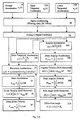
- Full implementation of the gait speedometer includes signal measurement 20, signal conditioning 22 which includes processing components such as amplifiers, filters and signal processing 24.
- a signal path or flow diagram shown in Figure 7 outlines the process. Signals emerge from the three primary transducers (normal and tangential accelerometers and inclinometer) and pass through signal conditions 22 which includes signal conditioning 26, by applying zero adjustments, gains, filters, etc. and analog to digital conversion 28. These signals from the accelerometers 12 and 14 are then combined using the angle to determine a gait kinematic result such as, for example, acceleration in a selected direction, velocity in a selected direction or distance in a selected direction. The simplest calculation is that for acceleration in a selected direction such as net horizontal acceleration 34. From acceleration in a selected direction instantaneous foot velocity i.e. horizontal velocity 36 and mean velocity 38 may be determined.
- the instantaneous foot velocity may if desired be transmitted via a wireless transmitter/receiver pair 5, 6 or signal wires 4 to a calculation/display unit 3 (such as a wristwatch sized device, portable calculation device or desktop computer) to store and display various velocity parameters along with many other gait indications (see Figure 6).
- a wireless transmitter/receiver pair 5, 6 or signal wires 4 to a calculation/display unit 3 (such as a wristwatch sized device, portable calculation device or desktop computer) to store and display various velocity parameters along with many other gait indications (see Figure 6).
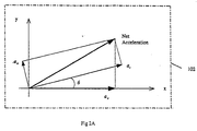
- Accelerometers are placed on the foot in essentially the same manner as described above so that the normal accelerations, a n , tangential accelerations, a t , and angular accelerations, ⁇ , preferably about the intersection 104 of the tangential and normal acceleration vectors a t and a n respectively can be simultaneously measured (see Figure 1A).
- the normal accelerometer measures 14 acceleration perpendicular to the base or sole 11 of the foot or shoe 10 which as above described provides the datum plane 100 defining surface 11 that defines the datum plane 100 for each stride when the sole 11 is at rest in the stance phase A of each stride.
- the tangential accelerometer 12 is sensitive to accelerations parallel to the base or sole 11 of the foot or shoe 10.
- Three accelerometers are mounted on a small aluminum bracket 200 fastened via a leveling wing 202 by two screws 204 to the heel counter of a shoe 10 as shown in Figure 3A.
- the upper and lower accelerometers 12A and 12B provide a pair of spaced substantially parallel accelerometers that measure tangential accelerations, while the middle normal accelerometer 14 measures the normal acceleration.
- the angular acceleration is determined by taking the difference of the accelerations generated by the upper and lower accelerometers divided by the distance between them (shown in Figure 3A by the distance r ). It is preferred that these accelerometers 12A and 12B be equally spaced from accelerometer 14, but this is not essential.
- the net tangential acceleration of the foot preferably is taken as the average of the upper and lower tangential accelerometers.
- This data is delivered to a computer 2 that then determines the acceleration, velocity arid other information which may be delivered to the use, for example, by audio or visual means such as an earphone or digital or analogue visual display or any other suitable means schematically indicated at 3.
- Suitable accelerometers are those made by Analog Devices (type ADXL50AH). An analog signal generated by such an accelerometer can be converted to a digital signal in a converter 28 ( Figure 15A).
- Typical normal and tangential accelerations for strides (4 in this example) of a subject jogging at 3 m/s (7 mph) are shown in Figure 4A.
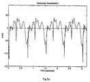
- a close-up of a tangential signal from the first stride shown in Figure 4A is shown in Figure 5A.
- the initial sharp spike corresponds to foot impact.
- the flatter section of the signal in the segment immediately following impact is the stance phase of the gait.
- the negative dip in the acceleration just after toe-off corresponds to the heel being raised as the knee flexes.
- the positive acceleration during the middle portion of the swing phase corresponds to the foot accelerating forward. During the latter portion of the swing phase, as the foot is slowed down in preparation for contact with the ground, there is a period of negative acceleration.
- Stride beginning and ending locations were found from the impact spikes when the subject's foot struck the ground.
- An algorithm based on finding a local maximum after the acceleration crosses a variable threshold value was used to find the impact spikes.
- the foot decelerates to a low speed before striking the ground but does not actually reach zero velocity until just slightly after impact.
- a location of approximately 0.1 seconds after foot strike was chosen to denote the beginning of a stride since this is approximately where the foot velocity is zero. This position is used to determine the datum plane 100 which corresponds with the plane of the sole 11 at this point in time. The time of 0.1 seconds works well for a normal human run. However, adjustments may be required where the gait is a walk or sprint.
- the measurement of the angular acceleration is accomplished by taking the difference between two parallel tangential accelerometers 12A and 12B.
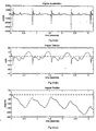
- a preferred method to convert drift is to first determine the mean angular acceleration ⁇ mean as indicated at 302 and to remove zero offset drift from ⁇ and ⁇ by subtracting each signal's mean for each individual stride before integrating as indicated at 304 in Figure 15A to define angular velocity ⁇ .
- the mean angular velocity ⁇ mean is determined as indicated at 306 in Figure 15A and then used to compute the angle as indicated at 308 and the position of the datum plane 100 using the offset o (0.1 seconds) described above as indicated at 310.
- Figure 7A shows the foot angle that results from the zeroing and integrating method on the data from Figure 6Aa (the zeroing and integrating is applied twice; once in the conversion of ⁇ and ⁇ and once again in going from ⁇ to). It is seen that it compares well with the independent from the infrared camera system that was used to film the subject.
- the indicated signal levels of the accelerometers can be adjusted to zero. This will correct for temperature drift and individual sensor biases.
- the indicated sensor angle in this orientation is used as a reference shoe angle that is used in conjunction with foot angle reset.
- the foot angle is set to the starting reference shoe angle for each new stride.
- Components of the tangential and normal acceleration are preferably combined using the foot tilt angle to find the horizontal acceleration, a x .
- a x ( a t1 +a t2 ) 2 cos ( ) - a n sin()
- the resulting horizontal acceleration is shown in Figure 8A.
- An integration of a x yields velocity v x parallel to plane 100 (or with appropriate changes any other selected direction) as a function of time, as shown in Figure 9A. It is seen that this signal also has low frequency drift. To correct the drift, zero offset was removed from the net horizontal acceleration since the horizontal velocity is zero at the beginning and end of each cycle.
- Figure 10A compares the velocities computed from the camera system and the velocities from using the zeroing and integrating algorithm on the acceleration data. Excellent agreement is seen in the form of the two curves. The final mean velocities agree to within a few percent.
- the mean tangential acceleration as indicated at 350 and generate a mean velocity as indicated by steps 34, 35, 36, and 38 described above and also shown in Figure 15A.
- Figure 16A shows a controlled experiment where the speed of a treadmill was selectively increased and the jogging speed of the runner measured using the present invention.
- the stopped line shows treadmill speed while the other plot is the results using the present invention. It is apparent that the results obtained using the present invention correlate very well with the actual speeds of the treadmill.
- the device and method described hereinbefore in this section assumes that during normal gait a subject's leg primarily swings through a plane parallel to that subject's sagittal plane.
- the plane parallel is defined herein as the sagittal plane. While this assumption works well for most subjects, in some the foot is not aligned in this plane during all or a portion of leg swing. Thus, although the foot moves through the desired plane, the foot is off-angled either inwardly (sometimes called medially rotated or "pigeon-toed") or outwardly of the sagittal plane (sometimes called laterally rotated or "duck walk").
- These foot alignments will cause an error in the measurements of the accelerometers.
- the accelerometers will only measure a portion of the actual acceleration and, therefore, the measured acceleration will be less than the actual acceleration.
- an additional accelerometer can be used, termed herein as the lateral accelerometer, which measures in a direction that is out of the plane of motion and, preferably, substantially perpendicular to the accelerometers currently used (12 and 14 in Figure 2).
- the lateral accelerometer would be aligned in the z-direction.
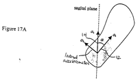
- the acceleration derived from the lateral accelerometer a L . If we consider a plan view of the shoe in movement through the sagittal plane where:
- the value of the sagittal acceleration (positive or negative) can be determined from the sign of a t .
- the sagittal acceleration in this model is treated as the tangential acceleration in the 2-D model and can by used with the normal acceleration to determine further gait kinematic results.
- the normal acceleration can be combined with the lateral acceleration first and then combined with the tangential acceleration.
- a device is useful for determining the degree of pronation in a person's gait.
- a person's foot sometimes rolls when viewed from the front or rear. This is termed pronation.
- the angle ⁇ between a plane parallel to the sagittal plane and the angular orientation of a person's foot is measured.
- the angular acceleration in this transverse plane can be recorded and then double integrated. This angular acceleration can be measured using a pair of parallel spaced accelerometers positioned to record acceleration in a plane perpendicular to the sagittal plane.
- Drift may be present in the signal. This drift can be removed by resetting the angle ⁇ at each foot impact. Where the determination of an absolute angle measurement is not required, resetting pronation foot angle ⁇ may not be necessary. In this case, it may be desirable to obtain an indication of the amplitude of the roll angle by noting the minimum and maximum roll angles during each stride.
- This method permits a runner, for example, to test out various running styles, running shoes and running surfaces and be able to determine in real time which factor most largely affects the impact forces.
- the invention may be used for many applications other than those described above including general kinematic measurements in one, two or three dimensions depending on the number and position of the accelerometers and angle measurement devices.
- the invention may be used in robotic controls, linkage and trajectory analysis, for example.
- the invention finds specific application in the biomedical field in prosthetics and as gait speedometers for walkers, runners or other athletes. Note that the use of this device is not limited to human applications.
- a primary advantage of the described invention is that all calculated gait parameters are available as a function of time. This opens up a wide range of real-time post-processing possibilities for use in scientific analysis and control operations.
- the accelerometers, etc. mounted on the counter of the shoe 10 they may be mounted at any appropriate location in fixed relation to the datum plane defining surface 11 or other such means. For example, they could be mounted to the shoe laces, pinned to the side of the shoe, built into the sole of the shoe or strapped to the foot.
Abstract
Description
- The present application is a continuation-in-part of United States patent application serial no. 08/949,472, filed October 14, 1997.
- The invention relates to a method and apparatus for measuring gait kinematics such as, for example, acceleration, velocity and position of gait based on foot movement analysis.
- The measurement and characterization of gait (i.e. human or animal) is performed by a wide range of methods. At one end of the scale is the measurement and analysis possibilities found in a well equipped bio-mechanical lab. The equipment in these labs typically includes automated 3D optical measurement systems, force plates and physiological output indicators. The output from these transducers are fed into a central computer that enables a wide range of analysis and display possibilities. At the other end of the spectrum is the simplified analysis performed with a ruler, stopwatch and trained clinical observations.
- The reasons determining gait kinematic properties (such as acceleration, velocity and position) range from: (i) personal interest, (ii) training and performance considerations of the serious athlete, (iii) rehabilitation of the disabled or (iv) for the design and analysis of footwear.
- From an athletic point of view, runners, joggers and walkers often like to know how far they have journeyed and how fast they have traveled, but have had only limited cumbersome ways to measure distance and speed. Distance can be measured after the fact with a calibrated bicycle or automobile or by traveling on a known premeasured route. For determining one's speed, a simple approach is to travel a known, fixed distance on a track or road and then record the length of time required to cover the distance. This method suffers from several limitations including (i) limited walking/running routes, (ii) speed indication at measured intervals only and (iii) only an average velocity is determined over the given distance.
- There are a number of portable pedometers that attempt to tackle the problem of measuring both distance and velocity. However, they have failed to gain wide spread use, because these devices are essentially limited to stride counting. Distance and speed can only be estimated if stride length consistency is assumed. This approach is inaccurate because an individual's stride length changes considerably from day to day or even within one session due to changes in terrain, fatigue, interval training, or other factors.
- U.S. patent no. 3,355,942 discloses a pedometer that counts strides based on compression cycles in a bellows under the heel and then estimates distance based on average stride length. The invention described in U.S. patent no. 4,741,001 uses a spirit-biased pendulum to count strides. The pedometer disclosed in U.S. patent no. 4,649,552 uses a step sensor sealed into an insole to count strides. The pedometer of U.S. patent no. 4,651,446 counts strides by detecting flexion of the instep. Other counting pedometers include those under U.S. patent no.'s 5,117,444, 5,065,414, 4,855,942, 4,510,704, 4,460,823, 4,371,945, 4,322,609, 4,053,755, 3,818,194 and 3,635,399.
- The majority of the patented pedometers are simply different methods of stride counting and do not address the problem of varying stride length. However, a pedometer listed under U.S. patent no. 4,371,945 uses ultrasonic emitters and sensors on alternate legs to measure the maximum distance between legs during each stride. While this is a significant improvement, this is only suitable for simple, low-speed gait patterns (no flight stage) and requires two sets of transducers; one on each leg.
- U.S. patent no. 5,097,706 describes a device for taking measurements of various components of the movement of a horse. The device carries six accelerometers disposed to measure accelerations along the x, y and z axis.
- Another U.S. patent no. 5,724,265 teaches a device that measures distance traveled, speed and height jumped of a person while running or walking. The device includes accelerometers and rotational sensors.
- The broad concept of using accelerometers for determining the velocity and distance traveled, for example by athletes, is also described in German Patent 4,222,373. This patent describes the use of an accelerometer and integration to determine velocity and route or position. This device apparently processes acceleration data continuously and thus has an accumulated error from drift so that in very short period of time, the resulting data contains significant inaccuracies. The inventor indicates that this device is useful for skiers, surfers, sailors, cyclists, etc. and thus is not related to a striding device or for measuring the kinematics of striding and would not be effective for that purpose.
- The Russian Patents 862074 and 885879 both by Volkov describe the attempts to overcome accumulated error in acceleration measuring devices by using a bar generator in combination with a summator and integrator. This described device does not make use of updated reference points and is thus also prone to accumulated drift.
- A paper entitled "Estimation of Speed and Inclination of Walking Using Neural Networks" by Aminian et al., Published in the IEEE, Transactions on Instrumentations and Measurements; Volume 44 #3, June 1995, describes a portable data logger designed to record body accelerations during walking and uses three orthogonal accelerometers placed on the waistbelt to measure forward, vertical and heel acceleration. By means of neural networks, it correlates the recorded signals to the desired gait velocity and angle of incline. The generality of this method is questionable and no other gait information is produced.
- The purpose of the device described herein is to provide a means to measure and display several gait parameters (that may include instantaneous and average accelerations and velocities as well as total distance traveled) by means of a simple, low-cost, portable device that can accommodate a wide variety of gaits and varying stride length. The device can be used for human or animal study.
- The present invention measures various results about each individual stride rather than assuming a given fixed length. With suitable signal processing, the device can accurately determine velocity and distance traveled. The present invention can be modified to give many other useful indicators to the user such as pronation angles and impact forces. Because it is based on acceleration measurements and analysis, it inherently contains data that correlate directly to impact forces. When integrated, the acceleration data yields both instantaneous and average velocity. A second integration of these signals yields distance information such as, for example, total distance traveled, stride length and height of foot off the ground. Other relevant pieces of information include stride rate (ie. cadence) and peak foot velocity. The invention also has the potential to measure biomechanic parameters such as force of impact and gait sway and can be used for off-angle feet.
- In broad terms, the present invention relates to a method of determining gait kinematics for a subject in each of a plurality of strides comprised during each stride defining a fresh datum plane, determining angles between a pair of accelerometers and said datum plane, said pair of accelerometers being adapted to measure acceleration in two directions, the two directions being separated by a known angle of greater than 0/, and being adapted to measure acceleration in a plane of motion substantially perpendicular to said datum plane, measuring acceleration in said plane of motion in said two directions, converting said accelerations to provide determination of a gait kinematic result for each said stride.
- The two directions are preferably separated by an angle of between about 45/ to 135/ and more preferably are substantially mutually perpendicular to facilitate determination of the gait kinematic result.
- The gait kinematic result can be, for example, details of foot motion, acceleration in a selected direction, velocity in a selected direction or distance in a selected direction. The selected direction is preferably either, parallel to the datum plane and in said plane of motion or perpendicular to said datum plane and in said plane of motion.
- The gait kinematic result can be integrated to provide further gait kinematic results. As an example, acceleration in a selected direction can be integrated to determine velocity in a selected direction. In addition, velocity in a selected direction can be integrated to determine distance traveled in a selected direction.
- The fresh datum plane is preferably defined when the pair of accelerometers are at a selected position relative to the datum plane. In particular, preferably, it can be determined that the pair of accelerometers are in the selected position by monitoring for foot impact with a surface just prior to the stance phase of the gait. The impact is defined by, for example, a rapid deceleration as determined by the pair of accelerometers or by a switch etc. actuated by impact. In one embodiment, the fresh datum plane is defined at impact plus 0.1 seconds, which is an estimate of the time, in a normal running stride, when the a sole plane of the foot is at rest on a surface in the stance phase of the gait. At this point, the angle between the accelerometers and the datum plane is reset to its original selected value. The original selected value defines the angle between one of the accelerometers and the datum plane, when the foot is at rest or in the stance phase. For example, where one of the accelerometers is positioned parallel to the datum plane during stance phase, the original selected value will be zero.
- The duration of a stride (ie. when a stride begins and ends) can be determined in any suitable way. In one embodiment, the stride is determined to be the activity between when the pair of accelerometers are at a selected position relative to the datum plane. In a preferred embodiment, the beginning and end of a stride are determined by observation of impact between the foot and a surface.
- Preferably, the method includes further steps for correcting for drift error.
- In one embodiment, the subject's mass is determined and used to determine impact force.
- In another embodiment, the method includes measuring acceleration in a lateral direction out of the plane of motion and converting said accelerations measured by the pair of accelerometers and the lateral accelerometer to provide determination of a gait kinematic result.
- Broadly the present invention also relates to a device for measuring gait kinematics comprising means for mounting a pair of accelerometers in a fixed relationship to a datum plane defining surface and said pair of accelerometers being adapted to measure acceleration in two directions, the two directions being separated by a known angle of greater than 0/, means defining a datum plane for each stride for which said gait kinematics is measured as a plane occupied by said datum plane defining surface when said datum plane defining surface is in a substantially stationary position in a stance phase of said stride, means for determining angular orientation of said accelerometers to said datum plane, means for determining a gait kinematic result based on measurements of acceleration by said pair of accelerometers and said determined angular orientation of said accelerometers to said datum plane.
- The two directions are preferably separated by an angle of between about 45/ to 135/ and more preferably are substantially mutually perpendicular to facilitate determination of the gait kinematic result.
- The gait kinematic result can be, for example, details of foot motion, acceleration in a selected direction, velocity in a selected direction or distance in a selected direction. The selected direction is preferably either, parallel to the datum plane and in said plane of motion or perpendicular to said datum plane and in said plane of motion.
- The device can preferably include a means for adjusting for drift error correction. A suitable means for drift error correction can include a system for determining the mean signal of any particular gait signal and applying the mean signal to the particular gait signal prior to integration to determine further gait kinematic result. In another embodiment, the means for adjusting for drift error correction is a system for using known physical limits of the derived signal such as, for example, velocity to account for drift.
- Preferably said means for determining angular orientation of said accelerometers to said datum plane comprises of a pair of spaced substantially parallel accelerometers mounted in fixed relation to said datum plane defining surface and means for calculating angular orientation based on differences in accelerations measured by said pair of spaced substantially parallel accelerometers.
- In one embodiment, useful for gait kinematic studies of off-angle feet, a lateral accelerometer is mounted in a fixed and known relationship to the pair of accelerometers and adapted to measure acceleration in a third direction selected to be different than the two directions and out of the plane of motion. Preferably, the lateral accelerometer is substantially perpendicular to the pair of accelerometers. The device can include a means for converting the acceleration measurements from the pair of accelerometers and the lateral accelerometer with angular orientation information to determine a gait kinematic result.
- In broad terms, the present invention also relates to a method of determining gait kinematics comprised during each stride defining a datum plane, determining angles between a pair of accelerometers and said datum plane, said pair of accelerometers being adapted to measure acceleration in two directions, the two directions being separated by a known angle of greater than 0/ and being adapted to measure acceleration in a plane of motion substantially perpendicular to said datum plane, measuring acceleration in said plane of motion in said two directions, converting said accelerations to provide determination of a gait kinematic result for each said stride and adjusting for drift error correction in said gait kinematic result.
- The two directions are preferably separated by an angle of between about 45/ to 135/ and more preferably are substantially mutually perpendicular to facilitate determination of the gait kinematic result.
- The gait kinematic result can be, for example, details of foot motion, acceleration in a selected direction, velocity in a selected direction or distance in a selected direction. The selected direction is preferably either, parallel to the datum plane and in said plane of motion or perpendicular to said datum plane and in said plane of motion.
- The step of adjusting for drift error correction can be carried out in various ways. In one embodiment, the adjusting step is made prior to the step of converting to provide a gait kinematic result while, in another embodiment, the adjusting is conducted after the step of converting. Adjusting can be made by data modification such as in the determination of the accelerations or the gait kinematic result or by modification of the determined gait kinematic result, such as by employing known limitations in the derived signal to adjust for the drift error correction. The adjusting step can provide correction which reduces or removes the drift error.
- In one embodiment, the method further comprises one or more integration steps to derive further gait kinematic results from the gait kinematic result. Adjusting for drift error correction can be conducted in any or all of the these integration steps. As an example, in one embodiment, the gait kinematic result is acceleration in a selected direction and the method further comprises integrating said acceleration in said selected direction to determine velocity in said selected direction. In such an embodiment, adjusting for drift error correction can be made by determining a mean acceleration in said selected direction and removing the mean acceleration from the acceleration in said selected direction prior to integrating to determine velocity in said selected direction. This adjusting step can be done in each stride. Mean values from one stride can be used for drift error correction in a subsequent stride.
- The method can further comprise integrating said velocity in a selected direction to determine distance traveled in a selected direction and, if desired, drift error correction can be made by determining a mean velocity in said selected direction and removing the mean velocity from the velocity in said selected direction prior to integrating to determine distance traveled in a selected direction.
- The datum plane, is preferably defined when the pair of accelerometers are at a selected position relative to the datum plane. In particular, preferably, it can be determined that the pair of accelerometers are in the selected position by monitoring for foot impact with a surface just prior to the stance phase of the gait. The impact is defined by, for example, a rapid deceleration as determined by the pair of accelerometers or by a switch etc. actuated by impact. In one embodiment, the fresh datum plane is defined at impact plus 0.1 seconds, which is an estimate of the time, in a normal running stride, when the a sole plane of the foot is at rest on a surface in the stance phase of the gait. At this point, the angle between the accelerometers and the datum plane is reset to its original selected value. The original selected value defines the angle between one of the accelerometers and the datum plane, when the foot is at rest or in the stance phase. For example, where one of the accelerometers is positioned parallel to the datum plane during stance phase, the original selected value will be zero. The datum plane resetting can alternatively use gait speed or foot plant duration information to modify the fresh datum plane selection.
- In another embodiment, the method further comprises converting said accelerations to provide acceleration substantially parallel to the datum plane and integrating said acceleration substantially parallel to the datum plane to define stride velocity and, if desired, drift error correction can be made by determining a mean horizontal acceleration and removing the mean acceleration substantially parallel to the datum plane from the acceleration substantially parallel to the datum plane prior to integrating to determine stride velocity.
- In one embodiment, the method further comprises integrating said velocity in a selected direction to define distance in said selected direction. Drift error correction can be made by determining a mean velocity in a selected direction and removing the mean velocity in a selected direction from the velocity in a selected direction prior to integrating to determine distance in a selected direction.
- Preferably said velocity in a selected direction is averaged over a plurality of strides to provide average velocity.
- In another embodiment, the step of adjusting for drift error correction employs known limitations in the derived signal. As an example, in a preferred embodiment the gait kinematics for velocity substantially parallel to the datum plane are determined and the velocity is adjusted such that no velocity value is negative, as velocity values are limited to a value greater than or equal to zero.
- Preferably said datum plane is defined by the position of a sole plane when said sole plane is at rest on a surface in a stance phase of said gait and wherein said pair of accelerometers are positioned in fixed relationship to said sole plane.
- Preferably said step of determining angles of a pair accelerometers is based on measurements of a pair of spaced substantially parallel accelerometers positioned at a selected angle to said sole plane.
- In one embodiment, the method determines the gait kinematics in each of a plurality of strides and a fresh datum plane is defined for each stride.
- Broadly the present invention also relates to a device for measuring gait kinematics comprising means for mounting pair(s) of accelerometers in a fixed relationship to a datum plane defining surface and said pair of accelerometers being adapted to measure acceleration in two directions, the two directions being separated by a known angle of greater than 0/, means defining a datum plane measured as a plane occupied by said datum plane defining surface when said datum plane defining surface is in a substantially stationary position in a stance phase of said stride, means for determining angular orientation of said accelerometers to said datum plane, means for determining a gait kinematic result based on measurements of acceleration by said pair of accelerometers and said determined angular orientation of said accelerometers to said datum plane and means for adjusting for drift error correction.
- The two directions are preferably separated by an angle of between about 45/ to 135/ and more preferably are substantially mutually perpendicular to facilitate determination of the gait kinematic result.
- The gait kinematic result can be, for example, details of foot motion, acceleration in a selected direction, velocity in a selected direction or distance in a selected direction. The selected direction is preferably either, parallel to the datum plane and in said plane of motion or perpendicular to said datum plane and in said plane of motion.
- The means for adjusting for drift error correction can include a system for determining the mean signal of any particular gait signal and applying the mean signal to a selected signal prior to integration to determine further gait kinematics. In another embodiment, the means for adjusting for drift error correction is a system for using known physical limits of the derived signal such as, for example, velocity to account for drift.
- Preferably said means for determining angular orientation of said accelerometers to said datum plane comprises of a pair of spaced substantially parallel accelerometers mounted in fixed relation to said datum plane defining surface and means for calculating angular orientation based on differences in accelerations measured by said pair of spaced substantially parallel accelerometers.
- Preferably said device further comprises means for converting the accelerations in two directions to obtain acceleration in said selected direction.
- Preferably said device further comprises means for converting the acceleration in said selected direction to velocity in said selected direction or to distance in said selected direction by means of integration.
- In accordance with another broad aspect fo the present invention, there is provided a device for measuring gait kinematics of a stride in a subject having an foot comprising means for mounting a pair of accelerometers in a fixed relationship to a datum plane defining surface and said pair of accelerometers being adapted to measure acceleration in two substantially parallel directions about an axis of rotation defined by movement of the foot, means defining a datum plane measured as a plane occupied by said datum plane defining surface when said datum plane defining surface is in a stationary position in a stance phase of said stride, and means for calculating angular orientation based on differences in accelerations measured by said pair of accelerometers.
- Preferably the axis of rotation is substantially parallel to the subject's sagittal plane and to the datum plane defining surface and, in a particularly preferred embodiment, is that axis about which the foot pronates.
- In accordance with another broad aspect, a method of determining pronation characteristics of a foot during a stride is provided comprising during each stride defining a datum plane, determining angular acceleration about an axis about which a foot pronates, converting the angular acceleration relative to the datum plane to determine an angle of pronation for the foot.
- Further features, objects and advantages will be evident from the following detailed description of the preferred embodiments of the present invention taken in conjunction with the accompanying drawings in which;
- Figure 1 is a schematic illustration of leg movement during walking or running.
- Figure 2 shows a shoe with accelerometers mounted thereon.
- Figure 3a and 3b the various angles and movement vectors of the shoe.
- Figures 4a, 4b and 4c are graphs of tangential acceleration, normal acceleration and angle of tilt of the foot respectively versus time.
- Figure 5a, 5b and 5c are plots of horizontal acceleration, foot velocity and speed of travel respectively versus time.
- Figure 6 is a more detailed illustration of the accelerometers mounted on the shoe, and schematically illustrating their connection to a computer.
- Figure 7 is a flow diagram of one mode of operation of the computer.
- Figure 1A shows the relationship of the normal, tangential and angular acceleration vectors and the shoe angle.
- Figure 2A shows how the vectors combine to produce the net acceleration vector.
- Figure 3A is a view similar to Figure 6 but showing a preferred arrangement.
- Figures 4Aa, 4Ab and 4Ac are plots of upper tangential acceleration, lower tangential acceleration and normal acceleration respectively versus time.
- Figure 5A is a plot of foot acceleration during a single step.
- Figures 6Aa, 6Ab and 6Ac are plots of angular acceleration, angular velocity and angular position respectively versus time.
- Figure 7A illustrates the accuracy of determined foot angle over time.
- Figure 8A is a plot of horizontal acceleration versus time.
- Figure 9A is a plot of drifting velocity versus time.
- Figure 10A is a plot of foot velocity versus time.
- Figure 11A and 13A are plots of angle of foot tilt versus time.
- Figure 12A and 14A are plots of horizontal foot velocity versus time.
- Figure 15A is a flow diagram similar to that shown in Figure 7.
- Figure 16A is a plot of velocity versus time showing correlation of the invention at different stride velocities.
- Figure 17A illustrates the determination of acceleration in a plane parallel to the sagittal plane.
- Figure 18A illustrates the foot pronation angle for a person.
-
- Figure 1 shows various stages of gait in a runner (two complete gait cycles are shown). The foot plants on the ground or supporting surface and comes to a complete rest in what is known as the stance phase of gait cycle as indicated at Points A in Figure 1. The foot then begins to accelerate as indicated at B in Figure 1 as the toe prepares to take off. The swing phase indicated at C follows as the leg passes through the air. Following this, the foot decelerates as it prepares to strike the ground as indicated at D and then repeats the cycle. These accelerations, decelerations and stoppings are utilized in the present invention to determine gait kinematics as will be described below.
- The fact that the foot plants and it becomes at rest or stationary during the stance phase A is used to provide a datum position to define a datum plane for each stride of the gait thereby eliminating accumulated error that would be adherent in the process if it wasn't iterated commencing at each stance phase A.
- The information to permit gait kinematic investigations is obtained via suitable sensors preferably acceleration sensors (accelerometers) 12 and 14 and a
tilt sensor 16 and this information is fed to asuitable computer 2 that performs calculations transferred from the data from the accelerometers into the information format fordelivery system 3 and displayed in the selected format (see Figure 6). - The information may be transferred directly as represented by the
arrow 4 or transferred by atransmitter 5 and then picked up by areceiver 6 in the display unit. - Two
accelerometers shoe 10. While the accelerometers can be disposed at any known and fixed position relative to each other to measure acceleration in two directions. Preferably,accelerometers shoe 10.Accelerometers tilt sensor 16 are in fixed position relative to a datum plane defining surface, which in the illustrated embodiment is aplane 11 defined by the sole of theshoe 10 as will be described below. The accelerometers are preferably (but not necessarily) orthogonally mounted as shown such that in the neutral standing position one is oriented vertically and one horizontally (Figure 2). Thevertical accelerometer 14 is referred to as the normal accelerometer and thehorizontal accelerometer 12 is referred to as the tangential accelerometer. These accelerometers measure the accelerations of the foot as the leg traverses through a plane parallel to the sagittal plane. While it is preferred to align these with one accelerometer (e.g. accelerometer 12) substantially parallel to thesale plane 11 and the other 14 substantially perpendicular thereto this is not essential. - The tilt angle is the angle between a
datum plane 100 which (Figure 3a), as will be described below is defined by a surface represented by thesole plane 11 of the foot orshoe 10. Thesole plane 11 has a fixed orientation relative to the twoaccelerometers shoe 10 defines a plane and the position of the sole on theshoe 10 in the stance position of the gait defines thedatum plane 100 for the next stride). The angle is the instantaneous angle between theplane 11 defined by the sole and the previously defineddatum plane 100 for that particular stride (see Figure 3a). - As the
shoe 10 is tilted during the stride, theaccelerometers - Since the accelerometers are mounted in the plane of motion 102 (see Figure 3b) the net acceleration is also parallel to the plane of
motion 102, i.e. the direction in which the stride is taken. This gait kinematic result for horizontal acceleration can be calculated by the following equation: - ax =
- acceleration in horizontal direction
- at =
- acceleration of
tangential accelerometer 12 - an =
- acceleration of
normal accelerometer 14 - =
- angle of tilt of accelerometer 12 (i.e. sole 11 of
shoe 10 with respect to plane 100 which in normal operation will represent the ground or surface on which the stride is taking place.) - Figures 4a, b, c show typical data gathered over several gait cycles for the two mutually
perpendicular accelerometers tilt sensor 16 versus time in second(s). This includes data collected by the tangential accelerometer (Figure 4a), by the normal accelerometer 14 (Figure 4b) and finally, Figure 4c shows the angle of foot tilt through the gait cycles. - The net horizontal acceleration ax , shown in Figure 5a, is integrated to yield the foot velocity as a function of time (Figure 5b). This velocity is averaged over several studies (three studies or cycles in this example) to yield the mean speed of travel shown as a straight line in Figure 5c. The mean velocity of the walker/runner, over the given time interval, corresponds with the calculated mean horizontal foot velocity during the same time period.
- Other gait kinematic results may also be easily derived from the measured data. These include, but are not limited to, stride rate, stride length, total distance traveled as well as angular velocities and accelerations.
- As above described, the gait speedometer shown in Figure 6 includes two linear accelerometers and an inclinometer or
tilt sensor 16 all amounted on the ankle orshoe 10 in fixed relation to the datum plane defining surface or sole 11. The required characteristics of the accelerometers and inclinometer/tilt sensor will be described and specific prototype selections that have been tested or considered are listed below. -
- The accelerometer transducers are mounted on the foot or shoe. It is necessary that they must not interfere or influence natural gait; this requires that they are small and lightweight.
- The device may be battery powered; this requires that the primary components and associated circuits possess low-power consumption characteristics.
- Human and many animal gaits are a very low frequency phenomenon; the accelerometers used in this device must be able to measure down to these frequencies.
- The accelerometer cluster is mounted on the foot or shoe and will thus be subjected to large impact forces and abuse. It is necessary that the accelerometers be rugged and durable to be able to survive in this environment.
- The linearity, repeatability and noise levels must be such that the accuracy of measurement is acceptable for the application.
- The accelerometers used in the development work of this invention are manufactured by Analog Devices (part no.'s ADXL50 and ADXL150/250). These accelerometers make use of micro-machining techniques to build the transducer into a silicon chip. This accounts for the small size, lower power consumption and accuracy of the devices.
- The invention described herein is not limited to the above mentioned accelerometer family. Other accelerometers are currently produced or are under development by different manufacturers and could be considered for this purpose. As well, other accelerometer technologies are candidates for this invention including strain-gauge and piezo-electric types.
-
- The transducer is mounted on the foot or shoe. It is necessary that it must not interfere or influence natural gait; this requires that it be small and lightweight.
- The device may be battery powered; this requires that the primary components and associated circuits possess low-power consumption characteristics.
- The transducer cluster is mounted on the foot or shoe and will thus be subjected to large impact forces and abuse. It is necessary that the inclinometers or tilt sensors be rugged and durable to be able to survive in this environment.
- The linearity, repeatability and noise levels must be such that the accuracy of measurement is acceptable for the application.
- To be able to determine the foot angle, many approaches are possible. It is possible to measure the foot angle directly by means of a tilt sensor or other suitable device. It is possible to measure the foot's angular velocity by means of a rate gyro or other suitable device and then integrate the signal once to determine the foot angle. It is possible to measure the foot's angular acceleration by means of an angular rotation accelerometer or other suitable device and then integrate the signal twice to determine the foot angle.
- Signal processing a pair of spaced parallel accelerometers to extract tilt information from the foot's angular acceleration, will be described in more detail herein below as it is the preferred system for determining the angle.
- Full implementation of the gait speedometer includes
signal measurement 20,signal conditioning 22 which includes processing components such as amplifiers, filters andsignal processing 24. A signal path or flow diagram shown in Figure 7 outlines the process. Signals emerge from the three primary transducers (normal and tangential accelerometers and inclinometer) and pass throughsignal conditions 22 which includessignal conditioning 26, by applying zero adjustments, gains, filters, etc. and analog todigital conversion 28. These signals from theaccelerometers horizontal acceleration 34. From acceleration in a selected direction instantaneous foot velocity i.e.horizontal velocity 36 andmean velocity 38 may be determined. - Once the instantaneous foot velocity has been determined 36, it may if desired be transmitted via a wireless transmitter/
receiver pair signal wires 4 to a calculation/display unit 3 (such as a wristwatch sized device, portable calculation device or desktop computer) to store and display various velocity parameters along with many other gait indications (see Figure 6). - A second embodiment of the invention is shown and will be described with reference to Figures 1A to 16A inclusive. Like reference numerals are used to indicate like parts in all embodiments.
- Accelerometers are placed on the foot in essentially the same manner as described above so that the normal accelerations, an , tangential accelerations, at , and angular accelerations, □, preferably about the
intersection 104 of the tangential and normal acceleration vectors at and an respectively can be simultaneously measured (see Figure 1A). The normal accelerometer measures 14 acceleration perpendicular to the base or sole 11 of the foot orshoe 10 which as above described provides thedatum plane 100 definingsurface 11 that defines thedatum plane 100 for each stride when the sole 11 is at rest in the stance phase A of each stride. Thetangential accelerometer 12 is sensitive to accelerations parallel to the base or sole 11 of the foot orshoe 10. The absolute direction of these accelerations vary continuously as the foot moves through a gait cycle. The measured angular acceleration is integrated twice to yield the foot angle . This angle is then used to resolve the normal and tangential accelerations into a net horizontal acceleration as shown in Figure 2A. The horizontal acceleration is then integrated to find the velocity of the foot as a function of time. The subject's mean speed of travel is determined by averaging the foot velocity over an integer number of foot strides. - The term horizontal or net horizontal acceleration velocity etc. is used for convenience as though the vector is horizontal i.e. parallel with a
horizontal datum plane 100. This vector will normally be parallel to thedatum plane 100 and the plane ofmotion 104. It also will be apparent that these vectors may be resolved into any selected plane or direction i.e. horizontal, vertical or somewhere in between. - It was chosen to place accelerometers on the foot because the foot follows a regular pattern of acceleration and deceleration as the foot travels through the air and comes to rest on the ground for each stride as indicated by the segments A, B, C and D of the stride in Figure 1. The small stationary period of time when the foot rests on the ground provides a useful point of reference for each stride and is used to define the
datum plane 100 for each stride. With this method, each stride is independently measured and thus there is no accumulating error if the measurement were interconnected. It makes no assumptions regarding stride length, gait type (walking, jogging or running) and it accounts for the flight phase of a running gait. - Three accelerometers (two tangential 12A and 12B and a normal 14) are mounted on a
small aluminum bracket 200 fastened via a levelingwing 202 by twoscrews 204 to the heel counter of ashoe 10 as shown in Figure 3A. The upper andlower accelerometers normal accelerometer 14 measures the normal acceleration. The angular acceleration is determined by taking the difference of the accelerations generated by the upper and lower accelerometers divided by the distance between them (shown in Figure 3A by the distance r). It is preferred that theseaccelerometers accelerometer 14, but this is not essential. The net tangential acceleration of the foot preferably is taken as the average of the upper and lower tangential accelerometers. This data is delivered to acomputer 2 that then determines the acceleration, velocity arid other information which may be delivered to the use, for example, by audio or visual means such as an earphone or digital or analogue visual display or any other suitable means schematically indicated at 3. - Suitable accelerometers are those made by Analog Devices (type ADXL50AH). An analog signal generated by such an accelerometer can be converted to a digital signal in a converter 28 (Figure 15A).
- Typical normal and tangential accelerations for strides (4 in this example) of a subject jogging at 3 m/s (7 mph) are shown in Figure 4A. A close-up of a tangential signal from the first stride shown in Figure 4A is shown in Figure 5A. The initial sharp spike corresponds to foot impact. The flatter section of the signal in the segment immediately following impact, is the stance phase of the gait. The negative dip in the acceleration just after toe-off corresponds to the heel being raised as the knee flexes. The positive acceleration during the middle portion of the swing phase corresponds to the foot accelerating forward. During the latter portion of the swing phase, as the foot is slowed down in preparation for contact with the ground, there is a period of negative acceleration.
- Stride beginning and ending locations were found from the impact spikes when the subject's foot struck the ground. An algorithm based on finding a local maximum after the acceleration crosses a variable threshold value was used to find the impact spikes. The foot decelerates to a low speed before striking the ground but does not actually reach zero velocity until just slightly after impact. A location of approximately 0.1 seconds after foot strike was chosen to denote the beginning of a stride since this is approximately where the foot velocity is zero. This position is used to determine the
datum plane 100 which corresponds with the plane of the sole 11 at this point in time. The time of 0.1 seconds works well for a normal human run. However, adjustments may be required where the gait is a walk or sprint. - It is preferred to measure angular acceleration and then integrate twice to determine the foot angle . The measurement of the angular acceleration is accomplished by taking the difference between two parallel
tangential accelerometers - After dividing the sequence into strides, the foot's angular position is determined. Coordinates are chosen so that the tilt is considered zero when the foot is in the zero velocity position i.e. the stance phase of the gait selected at 0.1 seconds after the foot strike i.e. a 0.1 second offset, and positive when the toe was pointed upwards as shown in Figure 1A. The foot's angular acceleration is found by subtracting the upper tangential acceleration, at1 , from the lower tangential acceleration, at2 . The angular acceleration is radians/sec2, □ , is calculated by dividing by the distance between the two accelerometers as indicated at 300 in Figure 15A.
- The resulting angular acceleration, from the data shown in Figure 4A, is shown in Figure 6Aa. This data was then integrated using an accumulating sum and the resulting angular velocity, ω (in radians/sec) as shown in Figure 6Ab. This result was once again integrated to produce the foot angle, , shown in Figure 6Ac. Note how the very noisy and non-descript appearing signal in Figure 6Aa is transformed into a very regular, smoothed function in Figure 6Ac. Low frequency drift is evident in the foot angle signal.
- A preferred method to convert drift is to first determine the mean angular acceleration □ mean as indicated at 302 and to remove zero offset drift from □ and ω by subtracting each signal's mean for each individual stride before integrating as indicated at 304 in Figure 15A to define angular velocity ω.
- The mean angular velocity ωmean is determined as indicated at 306 in Figure 15A and then used to compute the angle as indicated at 308 and the position of the
datum plane 100 using the offset o (0.1 seconds) described above as indicated at 310. - Figure 7A shows the foot angle that results from the zeroing and integrating method on the data from Figure 6Aa (the zeroing and integrating is applied twice; once in the conversion of □ and ω and once again in going from ω to). It is seen that it compares well with the independent from the infrared camera system that was used to film the subject.
- When the accelerometers are stationary and in a preferred configuration (ie. on the heel or on the laces), the indicated signal levels of the accelerometers can be adjusted to zero. This will correct for temperature drift and individual sensor biases.
- When the sensor cluster is attached at some other angle on the shoe, the indicated sensor angle in this orientation is used as a reference shoe angle that is used in conjunction with foot angle reset. In particular, instead of resetting the foot angle to zero on every foot strike, as is done in the heel mount position, the foot angle is set to the starting reference shoe angle for each new stride.
- Components of the tangential and normal acceleration are preferably combined using the foot tilt angle to find the horizontal acceleration, ax .
- A further improvement in results is usually achieved by using the assumption that the minimum foot velocity is zero. This suggests that if any part of the entire velocity curve dips below zero there has been some small error somewhere. If the error has not corrupted the shape of the curve, it can be corrected by simply shifting the entire curve up so that the new minimum is exactly zero.
- Generally, when the two parallel accelerometers are used to determine □, it is preferred to use the average of these two measurements to determine the mean, in this example the mean tangential acceleration, as indicated at 350 and generate a mean velocity as indicated by
steps - For the sake of coherence, all of the figures that have been shown so far have been of the same trial, a 3m/s jog. Figures 11A and 12A show the critical parameters, namely the foot angle, , and foot velocity, vx , for a 1.3 m/s walk, while Figures 13A and 14A show the same for a 3.8 m/s run respectively. In these figures, the calculated values from the method described herein are compared to video camera analysis of the same parameters. It is observed that there is excellent overall agreement between the foot angle and foot velocity for these cases.
- Figure 16A shows a controlled experiment where the speed of a treadmill was selectively increased and the jogging speed of the runner measured using the present invention. The stopped line shows treadmill speed while the other plot is the results using the present invention. It is apparent that the results obtained using the present invention correlate very well with the actual speeds of the treadmill.
- The device and method described hereinbefore in this section assumes that during normal gait a subject's leg primarily swings through a plane parallel to that subject's sagittal plane. For ease of reference, the plane parallel is defined herein as the sagittal plane. While this assumption works well for most subjects, in some the foot is not aligned in this plane during all or a portion of leg swing. Thus, although the foot moves through the desired plane, the foot is off-angled either inwardly (sometimes called medially rotated or "pigeon-toed") or outwardly of the sagittal plane (sometimes called laterally rotated or "duck walk"). These foot alignments will cause an error in the measurements of the accelerometers. In particular, the accelerometers will only measure a portion of the actual acceleration and, therefore, the measured acceleration will be less than the actual acceleration.
- To correct for the problem of off-angled feet, an additional accelerometer can be used, termed herein as the lateral accelerometer, which measures in a direction that is out of the plane of motion and, preferably, substantially perpendicular to the accelerometers currently used (12 and 14 in Figure 2). With reference to Figure 3b, the lateral accelerometer would be aligned in the z-direction. Referring to Figure 17A, the acceleration derived from the lateral accelerometer a L. If we consider a plan view of the shoe in movement through the sagittal plane where:
- a t = tangential acceleration
- a L = lateral acceleration
- a s = sagittal plane acceleration
- α = angle from sagittal plane.
-
- The acceleration in the sagittal plane, a s can be computed from
t L - The value of the sagittal acceleration (positive or negative) can be determined from the sign of a t. The angle, α, can be found from
- A device according to the present invention is useful for determining the degree of pronation in a person's gait. Referring to Figure 18A, a person's foot sometimes rolls when viewed from the front or rear. This is termed pronation. In assessing the degree of pronation of a person, the angle γ between a plane parallel to the sagittal plane and the angular orientation of a person's foot is measured. To be able to measure this angle, the angular acceleration in this transverse plane can be recorded and then double integrated. This angular acceleration can be measured using a pair of parallel spaced accelerometers positioned to record acceleration in a plane perpendicular to the sagittal plane.
- Alternately, the angular acceleration can be determined by a dedicated angular accelerometer. Alternatively, an angular rate sensor could be used to measure angular velocity and this signal could be integrated to indicate the desired angle, γ. Alternatively, a direct means of angle measurement could alternately be used for this purpose.
- Drift may be present in the signal. This drift can be removed by resetting the angle γ at each foot impact. Where the determination of an absolute angle measurement is not required, resetting pronation foot angle γ may not be necessary. In this case, it may be desirable to obtain an indication of the amplitude of the roll angle by noting the minimum and maximum roll angles during each stride.
- Many running injuries are caused from excessive forces imparted to the body during the foot-strike portion of the gait. This includes shin splints, stress fractures and various joint problems. When a person has these problems, it is often suggested that it is something in their running style (stride length, heel vs. mid-strike landing), current running shoes or running surface that is the culprit. Remedies are suggested and sometimes temporary success is found, only to return again. The difficulty with this type of problem is in its diagnosis and, in particular, how to determine which of these potential contributing factors is the problem. There are no low-cost measurement tools to determine the impact forces.
- It is well known that force and acceleration are directly related to each other from Newton's first law
- In a method according to the present invention, all necessary information is available to determine the acceleration of interest.
- To compare impact forces over a variety of scenarios, it is not necessary to have an absolute force measurement, but instead a relative force measurement will suffice. In particular, if it is determined that one uncalibrated force is some level, F0, one can observe how this level changes with any of the various factors (stride length, landing position, running shoes, surface, length of run, etc).
- This method permits a runner, for example, to test out various running styles, running shoes and running surfaces and be able to determine in real time which factor most largely affects the impact forces.
- It will be apparent that the invention may be used for many applications other than those described above including general kinematic measurements in one, two or three dimensions depending on the number and position of the accelerometers and angle measurement devices. Thus the invention may be used in robotic controls, linkage and trajectory analysis, for example. Clearly, the invention finds specific application in the biomedical field in prosthetics and as gait speedometers for walkers, runners or other athletes. Note that the use of this device is not limited to human applications.
- A primary advantage of the described invention, is that all calculated gait parameters are available as a function of time. This opens up a wide range of real-time post-processing possibilities for use in scientific analysis and control operations.
- While the disclosure has described the accelerometers, etc. mounted on the counter of the
shoe 10 they may be mounted at any appropriate location in fixed relation to the datumplane defining surface 11 or other such means. For example, they could be mounted to the shoe laces, pinned to the side of the shoe, built into the sole of the shoe or strapped to the foot. - Having described the invention, modifications will be evident to those skilled in the art without departing from the spirit of the invention as described above.
Claims (52)
- A method of determining gait kinematics for a subject in each of a plurality of strides comprised during each stride defining a fresh datum plane, determining angles between a pair of accelerometers and said datum plane, said pair of accelerometers being adapted to measure acceleration in two directions, the two directions being separated by a known angle of greater than 0/, and being adapted to measure acceleration in a plane of motion substantially perpendicular to said datum plane, measuring acceleration in said plane of motion in said two directions, converting said accelerations to provide determination of a gait kinematic result for each said stride.
- The method as defined in claim 1 wherein the two directions are substantially mutually perpendicular.
- The method as defined in claim 1 wherein the gait kinematic result is selected from the group consisting of acceleration in a selected direction, velocity in a selected direction or distance in a selected direction.
- The method as defined in claim 3 wherein the selected direction is parallel to the datum plane and in said plane of motion.
- The method as defined in claim 3 wherein the selected direction is perpendicular to said datum plane and in said plane of motion.
- The method as defined in claim 3 further comprising integrating the acceleration in a selected direction to determine velocity in a selected direction.
- The method as defined in claim 3 further comprising integrating velocity in a selected direction to define distance traveled in a selected direction.
- The method as defined in claim 1 wherein the fresh datum plane is preferably defined when the pair of accelerometers are at a selected position relative to the datum plane.
- The method as defined in claim 8 wherein the pair of accelerometers are in the selected position as indicated by foot impact with a surface just prior to a stance phase of the gait.
- The method as defined in claim 9 wherein the fresh datum plane is defined at foot impact plus 0.1 seconds
- The method of claim 1 wherein the gait kinematic result is horizontal acceleration and the method further comprising integrating said horizontal acceleration to define stride velocity.
- The method of claim 1 wherein the gait kinematic result is velocity in a selected direction and the method further comprises integrating said velocity in a selected direction to define distance in said selected direction.
- The method as defined in claim 1 further comprising adjusting for drift error correction.
- The method as defined in claim 1 further comprising determining the subject's mass and using the mass to determine impact force.
- The method as defined in claim 1 further comprising measuring acceleration in a lateral direction out of the plane of motion and converting said accelerations measured by the pair of accelerometers and the lateral accelerometer to provide acceleration in a selected direction.
- The method as defined in claim 15 wherein the lateral direction is substantially perpendicular to each of the pair of accelerometers.
- A device for measuring gait kinematics comprising means for mounting a pair of accelerometers in a fixed relationship to a datum plane defining surface, said pair of accelerometers being adapted to measure acceleration in two directions, the two directions being separated by a known angle of greater than 0/, means defining a datum plane for each stride for which said gait kinematics is measured as a plane occupied by said datum plane defining surface when said datum plane defining surface is in a stationary position in a stance phase of said stride, means for determining angular orientation of said accelerometers to said datum plane, means for determining a gait kinematic result based on measurements of acceleration by said pair of accelerometers and said determined angular orientation of said accelerometers to said datum plane.
- The device of claim 17 wherein the two directions are substantially mutually perpendicular.
- The device of claim 17 wherein the gait kinematic result is selected from the group consisting of acceleration in a selected direction, velocity in a selected direction or distance in a selected direction.
- The device of claim 19 wherein the selected direction is parallel to the datum plane and in said plane of motion.
- The device of claim 17 further comprising a means for adjusting for drift error correction.
- The device of claim 17 wherein the means for determining angular orientation of said accelerometers to said datum plane comprises of a pair of spaced substantially parallel accelerometers mounted in fixed relation to said datum plane defining surface and means for calculating angular orientation based on differences in accelerations measured by said pair of spaced substantially parallel accelerometers.
- The device of claim 17 wherein the pair of accelerometers is adapted to measure the acceleration in a plane of motion, and the device further comprising a lateral accelerometer mounted in a fixed and known relationship to the pair of mutually perpendicular accelerometers and adapted to measure acceleration in a third direction selected to be out of the plane of motion.
- The device of claim 23 wherein the lateral accelerometer is substantially perpendicular to the pair of accelerometers.
- A method of determining gait kinematics comprised during each stride defining a datum plane, determining angles between a pair of accelerometers and said datum plane, said pair of accelerometers being adapted to measure acceleration in two directions, the two directions being separated by a known angle of greater than 0/ and being adapted to measure acceleration in a plane of motion substantially perpendicular to said datum plane, measuring acceleration in said plane of motion in said two directions, converting said accelerations to provide determination of a gait kinematic result for each said stride and adjusting for drift error correction in said gait kinematic result.
- The method of claim 25 wherein the pair of accelerometers are substantially mutually perpendicular.
- The method of claim 25 wherein the gait kinematic result is selected from the group consisting of acceleration in a selected direction, velocity in a selected direction or distance in a selected direction.
- The method of claim 25 wherein the adjusting step is made prior to the step of converting to provide the gait kinematic result.
- The method of claim 25 wherein the adjusting step is conducted after the step of converting to provide the gait kinematic result.
- The method of claim 25 wherein the step of adjusting includes employing known limitations in the gait kinematic result.
- The method of claim 30 wherein any velocity in a selected direction results are adjusted to remove any negative velocity results therefrom.
- The method of claim 25 further comprising an integration step to derive further gait kinematic results from the gait kinematic result and adjusting for drift error correction in the integration steps.
- The method of claim 25 wherein the gait kinematic result is acceleration in said selected direction and the method further comprises integrating the acceleration in a selected direction to define velocity in said selected direction.
- The method of claim 33 further comprising determining a mean acceleration in said selected direction and removing the mean acceleration from the acceleration in said selected direction prior to integrating to determine velocity in said selected direction.
- The method of claim 34 conducted for each of a plurality of strides.
- The method of claim 34 wherein the mean acceleration in a selected direction is obtained from a previously determined gait kinematic result.
- The method of claim 25 wherein the gait kinematic result is velocity in a selected direction and the method further comprises integrating said velocity in a selected direction to define distance traveled in a selected direction.
- The method of claim 37 further comprising determining a mean velocity in said selected direction and removing the mean velocity from the velocity in said selected direction prior to integrating to determine distance traveled in a selected direction.
- The method of claim 25 wherein the gait kinematic result is horizontal acceleration and the method further comprising integrating said horizontal acceleration to define stride velocity.
- The method of claim 39 further comprising determining a mean horizontal acceleration and removing the mean horizontal acceleration from the horizontal acceleration prior to integrating to determine stride velocity.
- The method of claim 25 wherein the gait kinematic result is velocity in a selected direction and the method further comprises integrating said velocity in a selected direction to define distance in said selected direction.
- The method of claim 41 further comprising determining a mean velocity in a selected direction and removing the mean velocity in a selected direction from the velocity in a selected direction prior to integrating to determine distance in a selected direction.
- A device for measuring gait kinematics comprising means for mounting a pair of accelerometers in a fixed relationship to a datum plane defining surface and said pair of accelerometers being adapted to measure acceleration in two directions, the two directions being separated by a known angle of greater than 0/, means defining a datum plane measured as a plane occupied by said datum plane defining surface when said datum plane defining surface is in a stationary position in a stance phase of said stride, means for determining angular orientation of said accelerometers to said datum plane, means for determining a gait kinematic result based on measurements of acceleration by said pair of accelerometers and said determined angular orientation of said accelerometers to said datum plane and means for adjusting for drift error correction.
- The device of claim 43 wherein the two directions are substantially mutually perpendicular.
- The device of claim 43 wherein the gait kinematic result is selected from the group consisting of acceleration in a selected direction, velocity in a selected direction or distance in a selected direction.
- The device of claim 43 wherein the selected direction is parallel to the datum plane and in said plane of motion.
- The device of claim 43 wherein the means for adjusting for drift error correction is a system for determining the mean signal of any particular gait signal and applying the mean signal to the particular signal prior to integration to determine further gait kinematic results.
- The device of claim 43 wherein the means for adjusting for drift error correction is a system for using known physical limits of the derived signal to account for drift.
- A device for measuring gait kinematics of a stride in a subject having a foot, the device comprising means for mounting a pair of accelerometers in a fixed relationship to a datum plane defining surface, said pair of accelerometers being adapted to measure acceleration in two substantially parallel directions about an axis of rotation defined by movement of the foot, means defining a datum plane measured as a plane occupied by said datum plane defining surface when said datum plane defining surface is in a stationary position in a stance phase of said stride, and means for calculating angular orientation based on differences in accelerations measured by said pair of accelerometers.
- The device of claim 49 wherein the axis of the foot is substantially parallel to the subject's sagittal plane and with the datum plane defining surface.
- The device of claim 49 wherein the axis of rotation is that about which is defined pronation.
- A method of determining pronation characteristics of a foot during a stride comprising during each stride defining a datum plane, determining angular acceleration about an axis about which a foot pronates, converting the angular acceleration relative to the datum plane to determine an angle of pronation for the foot.
Applications Claiming Priority (2)
| Application Number | Priority Date | Filing Date | Title |
|---|---|---|---|
| US347305 | 1989-05-04 | ||
| US09/347,305 US6301964B1 (en) | 1997-10-14 | 1999-07-06 | Motion analysis system |
Publications (3)
| Publication Number | Publication Date |
|---|---|
| EP1066793A2 true EP1066793A2 (en) | 2001-01-10 |
| EP1066793A3 EP1066793A3 (en) | 2003-01-29 |
| EP1066793B1 EP1066793B1 (en) | 2008-08-20 |
Family
ID=23363172
Family Applications (1)
| Application Number | Title | Priority Date | Filing Date |
|---|---|---|---|
| EP00305626A Expired - Lifetime EP1066793B1 (en) | 1999-07-06 | 2000-07-04 | Motion analysis system |
Country Status (5)
| Country | Link |
|---|---|
| US (2) | US6301964B1 (en) |
| EP (1) | EP1066793B1 (en) |
| AT (1) | ATE405212T1 (en) |
| CA (1) | CA2312640C (en) |
| DE (1) | DE60039944D1 (en) |
Cited By (20)
| Publication number | Priority date | Publication date | Assignee | Title |
|---|---|---|---|---|
| EP1253404A2 (en) | 2001-04-23 | 2002-10-30 | Quentin Ladetto | Pedestrian navigation method and apparatus operative in a dead reckoning mode |
| DE10230446A1 (en) * | 2002-07-06 | 2004-01-15 | Deutsche Telekom Ag | Biometric access control procedures |
| WO2005091113A2 (en) | 2004-03-12 | 2005-09-29 | Vectronix Ag | Apparatus and method of determining 3d pedestrian motion by using projection planes |
| WO2007017471A1 (en) * | 2005-08-08 | 2007-02-15 | Csem Centre Suisse D'electronique Et De Microtechnique Sa Recherche Et Développement | Method and device for determining the speed of a runner |
| EP1754521A1 (en) * | 2005-08-16 | 2007-02-21 | CSEM Centre Suisse d'Electronique et de Microtechnique SA Recherche et Développement | Method and apparatus for determination of the efficiency of a running style |
| US7279009B2 (en) | 2000-03-29 | 2007-10-09 | Massachusetts Institute Of Technology | Speed-adaptive and patient-adaptive prosthetic knee |
| US7421369B2 (en) * | 2005-06-09 | 2008-09-02 | Sony Corporation | Activity recognition apparatus, method and program |
| EP2005887A1 (en) | 2007-06-23 | 2008-12-24 | Tanita Corporation | Gait assessment system |
| EP2014226A1 (en) | 2007-07-12 | 2009-01-14 | Polar Electro Oy | Portable apparatus |
| US7691154B2 (en) | 2004-05-07 | 2010-04-06 | össur hf | Systems and methods of controlling pressure within a prosthetic knee |
| US7774156B2 (en) * | 2007-07-12 | 2010-08-10 | Polar Electro Oy | Portable apparatus for monitoring user speed and/or distance traveled |
| US8617254B2 (en) | 2004-03-10 | 2013-12-31 | Ossur Hf | Control system and method for a prosthetic knee |
| FR2996112A1 (en) * | 2012-10-03 | 2014-04-04 | Assist Publ Hopitaux De Paris | Analyzing device for analyzing movements of foot of person for e.g. detecting asymmetry of walk, has connector for connecting inclinometer and microcontroller, for transmitting values measured by inclinometer to microcontroller |
| EP2016568B1 (en) * | 2006-04-20 | 2014-06-11 | Nike International Ltd. | Footwear products including data transmission capabilities |
| WO2015075307A1 (en) * | 2013-11-19 | 2015-05-28 | RLab Ab Oy | Method and system for exercise monitoring |
| CN108634960A (en) * | 2018-05-11 | 2018-10-12 | 浙江大学 | A kind of gait online test method for ectoskeleton wearer |
| US10251762B2 (en) | 2011-05-03 | 2019-04-09 | Victhom Laboratory Inc. | Impedance simulating motion controller for orthotic and prosthetic applications |
| US10290235B2 (en) | 2005-02-02 | 2019-05-14 | össur hf | Rehabilitation using a prosthetic device |
| CN111000567A (en) * | 2019-12-26 | 2020-04-14 | 浙江福祉医疗器械有限公司 | Human body walking state identification method for wearable device and wearable device |
| US10758778B1 (en) * | 2011-04-14 | 2020-09-01 | Thomas Chu-Shan Chuang | Stride change detection and correction |
Families Citing this family (265)
| Publication number | Priority date | Publication date | Assignee | Title |
|---|---|---|---|---|
| US7949488B2 (en) * | 1994-11-21 | 2011-05-24 | Nike, Inc. | Movement monitoring systems and associated methods |
| US6301964B1 (en) * | 1997-10-14 | 2001-10-16 | Dyhastream Innovations Inc. | Motion analysis system |
| US6390996B1 (en) * | 1998-11-09 | 2002-05-21 | The Johns Hopkins University | CPR chest compression monitor |
| IL130818A (en) | 1999-07-06 | 2005-07-25 | Intercure Ltd | Interventive-diagnostic device |
| US7127370B2 (en) * | 2000-01-07 | 2006-10-24 | Nocwatch International Inc. | Attitude indicator and activity monitoring device |
| US6522266B1 (en) * | 2000-05-17 | 2003-02-18 | Honeywell, Inc. | Navigation system, method and software for foot travel |
| US6836744B1 (en) * | 2000-08-18 | 2004-12-28 | Fareid A. Asphahani | Portable system for analyzing human gait |
| US7171331B2 (en) * | 2001-12-17 | 2007-01-30 | Phatrat Technology, Llc | Shoes employing monitoring devices, and associated methods |
| AU2002255568B8 (en) | 2001-02-20 | 2014-01-09 | Adidas Ag | Modular personal network systems and methods |
| US8452259B2 (en) | 2001-02-20 | 2013-05-28 | Adidas Ag | Modular personal network systems and methods |
| GB0106037D0 (en) * | 2001-03-12 | 2001-05-02 | Univ Strathclyde | Activity monitor |
| US20020133251A1 (en) * | 2001-03-15 | 2002-09-19 | International Business Machines Corporation, | Dynamic techniques for custom-fit knee replacments |
| US7540342B1 (en) | 2002-03-21 | 2009-06-02 | Robert John Ein | Virtual walker apparatus |
| US7496636B2 (en) * | 2002-06-19 | 2009-02-24 | International Business Machines Corporation | Method and system for resolving Universal Resource Locators (URLs) from script code |
| US6842991B2 (en) * | 2002-07-31 | 2005-01-18 | Robert W. Levi | Gyro aided magnetic compass |
| US6813582B2 (en) * | 2002-07-31 | 2004-11-02 | Point Research Corporation | Navigation device for personnel on foot |
| EP1538970B1 (en) | 2002-08-09 | 2020-06-17 | Intercure Ltd. | Generalized metronome for modification of biorhythmic activity |
| US7736394B2 (en) | 2002-08-22 | 2010-06-15 | Victhom Human Bionics Inc. | Actuated prosthesis for amputees |
| US7314490B2 (en) * | 2002-08-22 | 2008-01-01 | Victhom Human Bionics Inc. | Actuated leg prosthesis for above-knee amputees |
| DE10240608A1 (en) * | 2002-09-03 | 2004-03-18 | Lobo, Rocque, Prof. Dr. | Device for training the leg motor, arm motor and body motor |
| US7103471B2 (en) | 2002-09-20 | 2006-09-05 | Honeywell International Inc. | Multi-mode navigation device and method |
| US8672852B2 (en) * | 2002-12-13 | 2014-03-18 | Intercure Ltd. | Apparatus and method for beneficial modification of biorhythmic activity |
| US7480512B2 (en) | 2004-01-16 | 2009-01-20 | Bones In Motion, Inc. | Wireless device, program products and methods of using a wireless device to deliver services |
| US6859547B2 (en) * | 2003-01-25 | 2005-02-22 | The Mostert Group | Methods and computer-readable medium for tracking motion |
| US20050177802A1 (en) * | 2003-01-25 | 2005-08-11 | Mostert Paul S. | Methods and computer-readable medium for navigating between a plurality of discrete images |
| US8074559B2 (en) | 2007-02-06 | 2011-12-13 | Deka Products Limited Partnership | Dynamic support apparatus and system |
| US8956421B2 (en) | 2007-02-06 | 2015-02-17 | Deka Products Limited Partnership | Dynamic support apparatus and system |
| EP1616196A4 (en) | 2003-04-03 | 2009-05-20 | Univ Virginia | Method and system for the derivation of human gait characteristics and detecting falls passively from floor vibrations |
| US20040243148A1 (en) * | 2003-04-08 | 2004-12-02 | Wasielewski Ray C. | Use of micro- and miniature position sensing devices for use in TKA and THA |
| US7387611B2 (en) * | 2003-04-10 | 2008-06-17 | Matsushita Electric Industrial Co., Ltd. | Physical movement analyzer and physical movement analyzing method |
| US7198071B2 (en) * | 2003-05-02 | 2007-04-03 | Össur Engineering, Inc. | Systems and methods of loading fluid in a prosthetic knee |
| US6880258B2 (en) * | 2003-08-26 | 2005-04-19 | Horizon Hobby | Digital inclinometer and related methods |
| US20070068244A1 (en) * | 2003-10-17 | 2007-03-29 | M.B.T.L. Limited | Measuring forces in athletics |
| US7107180B2 (en) * | 2003-11-14 | 2006-09-12 | Ossur Hf | Method and system for determining an activity level in an individual |
| US7815689B2 (en) | 2003-11-18 | 2010-10-19 | Victhom Human Bionics Inc. | Instrumented prosthetic foot |
| US20050107889A1 (en) | 2003-11-18 | 2005-05-19 | Stephane Bedard | Instrumented prosthetic foot |
| JP2005156641A (en) * | 2003-11-20 | 2005-06-16 | Sony Corp | Playback mode control device and method |
| US20060184280A1 (en) * | 2005-02-16 | 2006-08-17 | Magnus Oddsson | System and method of synchronizing mechatronic devices |
| US7637959B2 (en) | 2004-02-12 | 2009-12-29 | össur hf | Systems and methods for adjusting the angle of a prosthetic ankle based on a measured surface angle |
| WO2005079712A2 (en) * | 2004-02-12 | 2005-09-01 | össur hf | System and method for motion-controlled foot unit |
| BE1015914A6 (en) * | 2004-02-24 | 2005-11-08 | Verhaert New Products & Servic | Device for determining the path made by any person on foot. |
| US20050195094A1 (en) * | 2004-03-05 | 2005-09-08 | White Russell W. | System and method for utilizing a bicycle computer to monitor athletic performance |
| JP2007528277A (en) | 2004-03-09 | 2007-10-11 | ハートレート・ゲームズ、インコーポレイテッド | Interactive exercise system with users |
| US20050283257A1 (en) * | 2004-03-10 | 2005-12-22 | Bisbee Charles R Iii | Control system and method for a prosthetic knee |
| US7447565B2 (en) * | 2004-05-06 | 2008-11-04 | John Cerwin | Electronic alignment system |
| WO2005115242A2 (en) * | 2004-05-24 | 2005-12-08 | Equusys, Incorporated | Animal instrumentation |
| BRPI0511360A (en) * | 2004-06-21 | 2008-03-25 | Equestron Llc | process and apparatus for assessing an animal's health and performance |
| AU2005264165A1 (en) | 2004-07-23 | 2006-01-26 | Intercure Ltd. | Apparatus and method for breathing pattern determination using a non-contact microphone |
| US7487043B2 (en) | 2004-08-30 | 2009-02-03 | Adams Phillip M | Relative positioning system |
| US7535368B2 (en) * | 2004-09-10 | 2009-05-19 | General Electric Company | System and method for measuring and reporting changes in walking speed |
| JP4591918B2 (en) * | 2004-11-01 | 2010-12-01 | 株式会社タニタ | Body movement measuring device |
| DE102004054220A1 (en) * | 2004-11-02 | 2006-05-11 | Hasomed Hard- und Software für die Medizin GmbH | Patient shoe inertial sensor attachment system has holder on U shaped stirrup held round heel by tensioned straps |
| US7583819B2 (en) * | 2004-11-05 | 2009-09-01 | Kyprianos Papademetriou | Digital signal processing methods, systems and computer program products that identify threshold positions and values |
| US8014896B2 (en) * | 2004-12-14 | 2011-09-06 | Honda Motor Co., Ltd. | Legged mobile robot and control program |
| US7254516B2 (en) | 2004-12-17 | 2007-08-07 | Nike, Inc. | Multi-sensor monitoring of athletic performance |
| CA2863933C (en) | 2004-12-22 | 2018-08-07 | Ossur Hf | Systems and methods for processing limb motion |
| DE102005004086A1 (en) | 2005-01-21 | 2006-07-27 | Xybermind Gmbh | Device and method for detecting movement |
| ITGE20050008A1 (en) * | 2005-02-08 | 2006-08-09 | Scienza Ind Tecnologia S R L | METHOD AND APPARATUS FOR MONITORING HUMAN BODY MOVEMENTS IN SPORTS AND MEDICAL AREA. |
| US8801802B2 (en) | 2005-02-16 | 2014-08-12 | össur hf | System and method for data communication with a mechatronic device |
| EP2818187A3 (en) | 2005-02-18 | 2015-04-15 | Zimmer, Inc. | Smart joint implant sensors |
| SE528516C2 (en) | 2005-04-19 | 2006-12-05 | Lisa Gramnaes | Combined active and passive leg prosthesis system and a method for performing a movement cycle with such a system |
| EP1877981A4 (en) * | 2005-05-02 | 2009-12-16 | Univ Virginia | Systems, devices, and methods for interpreting movement |
| ITMO20050166A1 (en) * | 2005-06-29 | 2006-12-30 | Infriccioli Amedeo | PROCEDURE FOR THE ACQUISITION, TREATMENT AND TRANSMISSION OF DATA LINKED TO HUMAN ENERGY CONSUMPTION DURING THE ACTIVITY OF QUOTIDIANA AND OR SPORTS PRETICA AND ITS DEVICE. |
| US20070054778A1 (en) * | 2005-08-29 | 2007-03-08 | Blanarovich Adrian M | Apparatus and system for measuring and communicating physical activity data |
| WO2007027808A2 (en) | 2005-09-01 | 2007-03-08 | össur hf | System and method for determining terrain transitions |
| US7531006B2 (en) | 2005-09-01 | 2009-05-12 | össur hf | Sensing system and method for motion-controlled foot unit |
| US8048172B2 (en) * | 2005-09-01 | 2011-11-01 | össur hf | Actuator assembly for prosthetic or orthotic joint |
| US7237446B2 (en) * | 2005-09-16 | 2007-07-03 | Raymond Chan | System and method for measuring gait kinematics information |
| US20070113674A1 (en) * | 2005-11-09 | 2007-05-24 | Rodriguez Hugo E | Systems of measuring, recording and evaluating the deformation and/or wear of structures and positioning with respect of their axis |
| US8055469B2 (en) * | 2006-03-03 | 2011-11-08 | Garmin Switzerland Gmbh | Method and apparatus for determining the attachment position of a motion sensing apparatus |
| US7467060B2 (en) * | 2006-03-03 | 2008-12-16 | Garmin Ltd. | Method and apparatus for estimating a motion parameter |
| KR100782502B1 (en) * | 2006-03-09 | 2007-12-05 | 삼성전자주식회사 | Apparatus and method for preventing loss of shoes using personal area network and shoes having loss prevention function |
| DE102006018545B4 (en) * | 2006-04-21 | 2009-12-31 | Andrea Wimmer | Pedometer for four-legged friends |
| US9390229B1 (en) | 2006-04-26 | 2016-07-12 | Dp Technologies, Inc. | Method and apparatus for a health phone |
| US8902154B1 (en) | 2006-07-11 | 2014-12-02 | Dp Technologies, Inc. | Method and apparatus for utilizing motion user interface |
| US7601126B2 (en) * | 2006-07-21 | 2009-10-13 | The Curators Of The University Of Missouri | Lameness evaluation systems and methods |
| WO2008030405A2 (en) * | 2006-09-06 | 2008-03-13 | Individual Monitoring Systems, Inc | Fully ambulatory, self-contained gait monitor |
| US7886618B2 (en) * | 2006-09-11 | 2011-02-15 | Orthocare Innovations Llc | Lower-limb prosthesis force and moment transducer |
| US8924248B2 (en) * | 2006-09-26 | 2014-12-30 | Fitbit, Inc. | System and method for activating a device based on a record of physical activity |
| US7768415B2 (en) | 2006-09-28 | 2010-08-03 | Nike, Inc. | Sensor device with persistent low power beacon |
| US8128410B2 (en) * | 2006-09-29 | 2012-03-06 | Nike, Inc. | Multi-mode acceleration-based athleticism measurement system |
| US7653508B1 (en) | 2006-12-22 | 2010-01-26 | Dp Technologies, Inc. | Human activity monitoring device |
| WO2008080231A1 (en) | 2007-01-05 | 2008-07-10 | Victhom Human Bionics Inc. | Joint actuation mechanism for a prosthetic and/or orthotic device having a compliant transmission |
| EP2120801B1 (en) | 2007-01-19 | 2018-04-11 | Victhom Laboratory Inc. | Reactive layer control system for prosthetic and orthotic devices |
| US8620353B1 (en) | 2007-01-26 | 2013-12-31 | Dp Technologies, Inc. | Automatic sharing and publication of multimedia from a mobile device |
| US8979943B2 (en) | 2007-02-06 | 2015-03-17 | Deka Products Limited Partnership | Arm prosthetic device |
| US10426638B2 (en) | 2007-02-06 | 2019-10-01 | Deka Products Limited Partnership | Arm prosthetic device |
| WO2010120402A1 (en) | 2009-04-13 | 2010-10-21 | Deka Products Limited Partnership | System and apparatus for orientation control |
| US9114030B2 (en) | 2007-02-06 | 2015-08-25 | Deka Products Limited Partnership | System for control of a prosthetic device |
| US8821587B2 (en) * | 2007-02-06 | 2014-09-02 | Deka Products Limited Partnership | Apparatus for control of a prosthetic |
| US8864845B2 (en) * | 2007-02-06 | 2014-10-21 | DEKA Limited Partnership | System for control of a prosthetic device |
| CA2679633C (en) * | 2007-02-06 | 2017-07-11 | Christopher C. Langenfeld | Arm prosthetic device |
| US11779476B2 (en) | 2007-02-06 | 2023-10-10 | Deka Products Limited Partnership | Arm prosthetic device |
| EP2114295B1 (en) * | 2007-02-06 | 2015-07-01 | DEKA Products Limited Partnership | Dynamic support apparatus |
| US8449624B2 (en) * | 2007-02-06 | 2013-05-28 | Deka Products Limited Partnership | Arm prosthetic device |
| US8949070B1 (en) | 2007-02-08 | 2015-02-03 | Dp Technologies, Inc. | Human activity monitoring device with activity identification |
| US7753861B1 (en) | 2007-04-04 | 2010-07-13 | Dp Technologies, Inc. | Chest strap having human activity monitoring device |
| FI121289B (en) | 2007-04-13 | 2010-09-15 | Vti Technologies Oy | Method and apparatus for measuring a moving person's forward movement |
| JP4842885B2 (en) | 2007-05-23 | 2011-12-21 | トヨタ自動車株式会社 | In-vehicle device control system and vehicle |
| FI122712B (en) * | 2007-07-11 | 2012-06-15 | Vti Technologies Oy | Method and apparatus for measuring the forward movement of a moving person |
| US8555282B1 (en) | 2007-07-27 | 2013-10-08 | Dp Technologies, Inc. | Optimizing preemptive operating system with motion sensing |
| US7647196B2 (en) * | 2007-08-08 | 2010-01-12 | Dp Technologies, Inc. | Human activity monitoring device with distance calculation |
| US8360904B2 (en) | 2007-08-17 | 2013-01-29 | Adidas International Marketing Bv | Sports electronic training system with sport ball, and applications thereof |
| US8221290B2 (en) | 2007-08-17 | 2012-07-17 | Adidas International Marketing B.V. | Sports electronic training system with electronic gaming features, and applications thereof |
| US8702430B2 (en) | 2007-08-17 | 2014-04-22 | Adidas International Marketing B.V. | Sports electronic training system, and applications thereof |
| US20090099812A1 (en) * | 2007-10-11 | 2009-04-16 | Philippe Kahn | Method and Apparatus for Position-Context Based Actions |
| JP5131908B2 (en) * | 2007-11-30 | 2013-01-30 | 任天堂株式会社 | Step count calculation program, step count calculation device, step count calculation system, and step count calculation method |
| DE102007063160A1 (en) * | 2007-12-29 | 2009-07-09 | Puma Aktiengesellschaft Rudolf Dassler Sport | Method for influencing the pronation behavior of a shoe |
| PT103933A (en) * | 2008-01-17 | 2009-07-17 | Univ Do Porto | PORTABLE DEVICE AND METHOD FOR MEASURING AND CALCULATING DYNAMIC PARAMETERS OF PEDESTRIAN LOCOMOTION |
| US8852128B2 (en) * | 2008-03-12 | 2014-10-07 | University Of Cincinnati | Computer system and method for assessing dynamic bone quality |
| CN102036626B (en) | 2008-03-24 | 2014-07-02 | 奥瑟Hf公司 | Transfemoral prosthetic systems and methods for operating the same |
| US8224575B2 (en) * | 2008-04-08 | 2012-07-17 | Ensco, Inc. | Method and computer-readable storage medium with instructions for processing data in an internal navigation system |
| US8320578B2 (en) * | 2008-04-30 | 2012-11-27 | Dp Technologies, Inc. | Headset |
| US8285344B2 (en) * | 2008-05-21 | 2012-10-09 | DP Technlogies, Inc. | Method and apparatus for adjusting audio for a user environment |
| US8029566B2 (en) * | 2008-06-02 | 2011-10-04 | Zimmer, Inc. | Implant sensors |
| US8996332B2 (en) | 2008-06-24 | 2015-03-31 | Dp Technologies, Inc. | Program setting adjustments based on activity identification |
| WO2010006340A1 (en) * | 2008-07-11 | 2010-01-14 | Orthocare Innovations Llc | Robotic prosthesis alignment device and alignment surrogate device |
| US8187182B2 (en) | 2008-08-29 | 2012-05-29 | Dp Technologies, Inc. | Sensor fusion for activity identification |
| US9409052B2 (en) | 2008-10-03 | 2016-08-09 | Adidas Ag | Program products, methods, and systems for providing location-aware fitness monitoring services |
| US8872646B2 (en) * | 2008-10-08 | 2014-10-28 | Dp Technologies, Inc. | Method and system for waking up a device due to motion |
| EP2186478A1 (en) * | 2008-11-14 | 2010-05-19 | HASOMED Hard- und Software für Medizin GmbH | Method and device for analysing the human movement cycle |
| US8880377B2 (en) | 2008-12-22 | 2014-11-04 | Polar Electro Oy | Overall motion determination |
| US8979774B2 (en) * | 2009-01-13 | 2015-03-17 | Robert Bosch Gmbh | Activity monitoring device and method |
| US9267862B1 (en) * | 2009-02-18 | 2016-02-23 | Sensr Monitoring Technologies Llc | Sensor and monitoring system for structural monitoring |
| US20100250179A1 (en) * | 2009-03-27 | 2010-09-30 | Thomas Mariano | Method and apparatus for measuring and estimating subject motion in variable signal reception environments |
| US9529437B2 (en) * | 2009-05-26 | 2016-12-27 | Dp Technologies, Inc. | Method and apparatus for a motion state aware device |
| DE102009028072A1 (en) * | 2009-07-29 | 2011-02-10 | Robert Bosch Gmbh | Calibrating method for calibrating step counter fixed at e.g. belt of chronic sick patient for detecting movement of patient, during movement conditions in medical area, involves determining phase angle between for determining signal |
| FR2948802B1 (en) | 2009-07-29 | 2014-12-05 | Movea | SYSTEM AND METHOD FOR COUNTING ELEMENTARY DISPLACEMENT OF A PERSON |
| US20110035185A1 (en) * | 2009-08-10 | 2011-02-10 | Thorsten Habel | Sensor-based Tracking of Variable Locomotion |
| US8744783B2 (en) * | 2009-08-27 | 2014-06-03 | The United States Of America As Represented By The Secretary Of The Navy | System and method for measuring power generated during legged locomotion |
| JP5504810B2 (en) * | 2009-10-06 | 2014-05-28 | オムロンヘルスケア株式会社 | Walking posture determination device, control program, and control method |
| FR2951628B1 (en) * | 2009-10-22 | 2012-07-13 | Genourob | IMPROVEMENTS IN THE DEVICE FOR DETECTING AND FOLLOWING A TOTAL OR PARTIAL LESION OF CROSS LIGAMENT BEFORE THE KNEE, BY COMPARISON BETWEEN THE TWO MEMBERS |
| US9068844B2 (en) | 2010-01-08 | 2015-06-30 | Dp Technologies, Inc. | Method and apparatus for an integrated personal navigation system |
| US8825435B2 (en) * | 2010-02-19 | 2014-09-02 | Itrack, Llc | Intertial tracking system with provision for position correction |
| JP5115673B2 (en) * | 2010-03-16 | 2013-01-09 | 株式会社村田製作所 | Walking shoes |
| US9844447B2 (en) | 2010-04-09 | 2017-12-19 | Deka Products Limited Partnership | System and apparatus for robotic device and methods of using thereof |
| US20110254689A1 (en) * | 2010-04-14 | 2011-10-20 | Carl Snyder | Door alarm and method of use |
| US20150342513A1 (en) * | 2010-07-01 | 2015-12-03 | Industrial Technology Research Institute | System and Method for Analyzing Biomechanics |
| US10289753B2 (en) | 2010-07-07 | 2019-05-14 | Simon Fraser University | Methods and systems for guidance of human locomotion |
| US9940682B2 (en) | 2010-08-11 | 2018-04-10 | Nike, Inc. | Athletic activity user experience and environment |
| EP2422698A1 (en) | 2010-08-26 | 2012-02-29 | Nederlandse Organisatie voor toegepast -natuurwetenschappelijk onderzoek TNO | Method and system for determining the walking or running speed of a person |
| US9030294B2 (en) | 2010-09-20 | 2015-05-12 | Pulsar Informatics, Inc. | Systems and methods for collecting biometrically verified actigraphy data |
| US8738323B2 (en) | 2010-09-30 | 2014-05-27 | Fitbit, Inc. | Methods and systems for metrics analysis and interactive rendering, including events having combined activity and location information |
| US8775120B2 (en) | 2010-09-30 | 2014-07-08 | Fitbit, Inc. | Method of data synthesis |
| US8738321B2 (en) | 2010-09-30 | 2014-05-27 | Fitbit, Inc. | Methods and systems for classification of geographic locations for tracked activity |
| US11243093B2 (en) | 2010-09-30 | 2022-02-08 | Fitbit, Inc. | Methods, systems and devices for generating real-time activity data updates to display devices |
| US9390427B2 (en) | 2010-09-30 | 2016-07-12 | Fitbit, Inc. | Methods, systems and devices for automatic linking of activity tracking devices to user devices |
| US9253168B2 (en) | 2012-04-26 | 2016-02-02 | Fitbit, Inc. | Secure pairing of devices via pairing facilitator-intermediary device |
| US8954291B2 (en) | 2010-09-30 | 2015-02-10 | Fitbit, Inc. | Alarm setting and interfacing with gesture contact interfacing controls |
| US9188460B2 (en) | 2010-09-30 | 2015-11-17 | Fitbit, Inc. | Methods, systems and devices for generating real-time activity data updates to display devices |
| US9241635B2 (en) | 2010-09-30 | 2016-01-26 | Fitbit, Inc. | Portable monitoring devices for processing applications and processing analysis of physiological conditions of a user associated with the portable monitoring device |
| US8762102B2 (en) | 2010-09-30 | 2014-06-24 | Fitbit, Inc. | Methods and systems for generation and rendering interactive events having combined activity and location information |
| US9167991B2 (en) | 2010-09-30 | 2015-10-27 | Fitbit, Inc. | Portable monitoring devices and methods of operating same |
| US8694282B2 (en) | 2010-09-30 | 2014-04-08 | Fitbit, Inc. | Methods and systems for geo-location optimized tracking and updating for events having combined activity and location information |
| US8762101B2 (en) | 2010-09-30 | 2014-06-24 | Fitbit, Inc. | Methods and systems for identification of event data having combined activity and location information of portable monitoring devices |
| US8712724B2 (en) | 2010-09-30 | 2014-04-29 | Fitbit, Inc. | Calendar integration methods and systems for presentation of events having combined activity and location information |
| US10983945B2 (en) | 2010-09-30 | 2021-04-20 | Fitbit, Inc. | Method of data synthesis |
| US8954290B2 (en) | 2010-09-30 | 2015-02-10 | Fitbit, Inc. | Motion-activated display of messages on an activity monitoring device |
| US8620617B2 (en) | 2010-09-30 | 2013-12-31 | Fitbit, Inc. | Methods and systems for interactive goal setting and recommender using events having combined activity and location information |
| US8781791B2 (en) | 2010-09-30 | 2014-07-15 | Fitbit, Inc. | Touchscreen with dynamically-defined areas having different scanning modes |
| US9148483B1 (en) | 2010-09-30 | 2015-09-29 | Fitbit, Inc. | Tracking user physical activity with multiple devices |
| US8751194B2 (en) | 2010-09-30 | 2014-06-10 | Fitbit, Inc. | Power consumption management of display in portable device based on prediction of user input |
| US10004406B2 (en) | 2010-09-30 | 2018-06-26 | Fitbit, Inc. | Portable monitoring devices for processing applications and processing analysis of physiological conditions of a user associated with the portable monitoring device |
| US8812259B2 (en) | 2010-09-30 | 2014-08-19 | Fitbit, Inc. | Alarm setting and interfacing with gesture contact interfacing controls |
| US8768648B2 (en) | 2010-09-30 | 2014-07-01 | Fitbit, Inc. | Selection of display power mode based on sensor data |
| US8805646B2 (en) | 2010-09-30 | 2014-08-12 | Fitbit, Inc. | Methods, systems and devices for linking user devices to activity tracking devices |
| US8849610B2 (en) | 2010-09-30 | 2014-09-30 | Fitbit, Inc. | Tracking user physical activity with multiple devices |
| US9310909B2 (en) | 2010-09-30 | 2016-04-12 | Fitbit, Inc. | Methods, systems and devices for physical contact activated display and navigation |
| US8744804B2 (en) | 2010-09-30 | 2014-06-03 | Fitbit, Inc. | Methods, systems and devices for automatic linking of activity tracking devices to user devices |
| US8744803B2 (en) | 2010-09-30 | 2014-06-03 | Fitbit, Inc. | Methods, systems and devices for activity tracking device data synchronization with computing devices |
| US8615377B1 (en) | 2010-09-30 | 2013-12-24 | Fitbit, Inc. | Methods and systems for processing social interactive data and sharing of tracked activity associated with locations |
| US9202111B2 (en) | 2011-01-09 | 2015-12-01 | Fitbit, Inc. | Fitness monitoring device with user engagement metric functionality |
| US8475367B1 (en) | 2011-01-09 | 2013-07-02 | Fitbit, Inc. | Biometric monitoring device having a body weight sensor, and methods of operating same |
| JP2014504943A (en) | 2011-02-07 | 2014-02-27 | ニュー バランス アスレティック シュー,インコーポレーテッド | System and method for monitoring athletic performance |
| US10363453B2 (en) | 2011-02-07 | 2019-07-30 | New Balance Athletics, Inc. | Systems and methods for monitoring athletic and physiological performance |
| US9095251B2 (en) * | 2011-02-16 | 2015-08-04 | Bryce Benjamin Purks | Circuits, systems, and methods for monitoring and coaching a person's sideways spacing foot placement and roll, shoe life, and other running/walking characteristics |
| US8573982B1 (en) | 2011-03-18 | 2013-11-05 | Thomas C. Chuang | Athletic performance and technique monitoring |
| US8738925B1 (en) | 2013-01-07 | 2014-05-27 | Fitbit, Inc. | Wireless portable biometric device syncing |
| US9186091B2 (en) | 2011-07-11 | 2015-11-17 | Litecure, Llc | Systems and methods of analyzing stance of animals |
| US9082208B2 (en) * | 2011-07-12 | 2015-07-14 | Spirit Aerosystems, Inc. | System and method for locating and displaying aircraft information |
| EP2556795A1 (en) | 2011-08-09 | 2013-02-13 | Nederlandse Organisatie voor toegepast -natuurwetenschappelijk onderzoek TNO | Method and system for feedback on running style |
| US9374659B1 (en) | 2011-09-13 | 2016-06-21 | Dp Technologies, Inc. | Method and apparatus to utilize location data to enhance safety |
| US9140717B2 (en) | 2011-09-20 | 2015-09-22 | The Regents Of The University Of Michigan | Apparatus and method for identifying and analyzing the free flight dynamics of a body |
| US8898033B2 (en) * | 2011-10-12 | 2014-11-25 | GM Global Technology Operations LLC | Vehicle stability systems and methods |
| US9532877B2 (en) | 2011-11-11 | 2017-01-03 | Springactive, Inc. | Robotic device and method of using a parallel mechanism |
| US10543109B2 (en) | 2011-11-11 | 2020-01-28 | Össur Iceland Ehf | Prosthetic device and method with compliant linking member and actuating linking member |
| US9339691B2 (en) | 2012-01-05 | 2016-05-17 | Icon Health & Fitness, Inc. | System and method for controlling an exercise device |
| US9017419B1 (en) | 2012-03-09 | 2015-04-28 | össur hf | Linear actuator |
| US9044346B2 (en) | 2012-03-29 | 2015-06-02 | össur hf | Powered prosthetic hip joint |
| US9186549B2 (en) * | 2012-04-04 | 2015-11-17 | Icon Health & Fitness, Inc. | Systems, methods, and devices for gathering and transmitting exercise related data |
| US9737261B2 (en) | 2012-04-13 | 2017-08-22 | Adidas Ag | Wearable athletic activity monitoring systems |
| US9257054B2 (en) | 2012-04-13 | 2016-02-09 | Adidas Ag | Sport ball athletic activity monitoring methods and systems |
| US9504414B2 (en) | 2012-04-13 | 2016-11-29 | Adidas Ag | Wearable athletic activity monitoring methods and systems |
| US10922383B2 (en) | 2012-04-13 | 2021-02-16 | Adidas Ag | Athletic activity monitoring methods and systems |
| US8827721B2 (en) | 2012-06-08 | 2014-09-09 | Zoll Medical Corporation | Method of measuring abdominal thrusts for clinical use and training |
| US9641239B2 (en) | 2012-06-22 | 2017-05-02 | Fitbit, Inc. | Adaptive data transfer using bluetooth |
| US8983637B2 (en) | 2012-07-30 | 2015-03-17 | Mapmyfitness, Inc. | Determining authenticity of reported fitness-related activities |
| US9032794B2 (en) | 2012-08-09 | 2015-05-19 | The Regents Of The University Of Michigan | Pitcher training apparatus and method using a ball with an embedded inertial measurement unit |
| US10042893B2 (en) | 2012-10-31 | 2018-08-07 | Under Armour, Inc. | System and method for personal and peer performance ranking of outdoor activities |
| WO2014089238A1 (en) * | 2012-12-04 | 2014-06-12 | Mapmyfitness, Inc. | Gait analysis system and method |
| WO2014089331A1 (en) | 2012-12-06 | 2014-06-12 | Ossur Hf | Electrical stimulation for orthopedic devices |
| WO2014090263A1 (en) | 2012-12-12 | 2014-06-19 | Puma SE | Method for determining the distance covered by a person |
| US9039614B2 (en) | 2013-01-15 | 2015-05-26 | Fitbit, Inc. | Methods, systems and devices for measuring fingertip heart rate |
| US8827906B2 (en) | 2013-01-15 | 2014-09-09 | Fitbit, Inc. | Methods, systems and devices for measuring fingertip heart rate |
| US9728059B2 (en) | 2013-01-15 | 2017-08-08 | Fitbit, Inc. | Sedentary period detection utilizing a wearable electronic device |
| US9295413B2 (en) | 2013-01-17 | 2016-03-29 | Garmin Switzerland Gmbh | Fitness monitor |
| US9561118B2 (en) | 2013-02-26 | 2017-02-07 | össur hf | Prosthetic foot with enhanced stability and elastic energy return |
| US9500464B2 (en) | 2013-03-12 | 2016-11-22 | Adidas Ag | Methods of determining performance information for individuals and sports objects |
| WO2014153158A1 (en) | 2013-03-14 | 2014-09-25 | Icon Health & Fitness, Inc. | Strength training apparatus with flywheel and related methods |
| WO2014159114A1 (en) | 2013-03-14 | 2014-10-02 | össur hf | Prosthetic ankle: a method of controlling based on adaptation to speed |
| EP2783630A1 (en) | 2013-03-27 | 2014-10-01 | ETH Zurich | Human motion analysis method and device |
| US9213889B2 (en) * | 2013-03-28 | 2015-12-15 | The Regents Of The University Of Michigan | Athlete speed prediction method using data from attached inertial measurement unit |
| US9504407B2 (en) * | 2013-05-21 | 2016-11-29 | Chin Keong Lam | Method and system for processing runner data |
| US9063164B1 (en) | 2013-10-02 | 2015-06-23 | Fitbit, Inc. | Collaborative activity-data acquisition |
| US9220443B2 (en) | 2013-10-31 | 2015-12-29 | Zoll Medical Corporation | CPR chest compression monitor for infants |
| EP3623020A1 (en) | 2013-12-26 | 2020-03-18 | Icon Health & Fitness, Inc. | Magnetic resistance mechanism in a cable machine |
| US9031812B2 (en) | 2014-02-27 | 2015-05-12 | Fitbit, Inc. | Notifications on a user device based on activity detected by an activity monitoring device |
| US10433612B2 (en) | 2014-03-10 | 2019-10-08 | Icon Health & Fitness, Inc. | Pressure sensor to quantify work |
| EP2924675A1 (en) | 2014-03-26 | 2015-09-30 | Spinnosport Oy | Educational gadget, system and method for teaching correct exercise or its correct trajectory |
| US9449365B2 (en) | 2014-04-11 | 2016-09-20 | Fitbit, Inc. | Personalized scaling of graphical indicators |
| US9449409B2 (en) | 2014-04-11 | 2016-09-20 | Fitbit, Inc. | Graphical indicators in analog clock format |
| EP3128958B1 (en) | 2014-04-11 | 2019-08-07 | Össur HF | Prosthetic foot with removable flexible members |
| US9288298B2 (en) | 2014-05-06 | 2016-03-15 | Fitbit, Inc. | Notifications regarding interesting or unusual activity detected from an activity monitoring device |
| US9849361B2 (en) | 2014-05-14 | 2017-12-26 | Adidas Ag | Sports ball athletic activity monitoring methods and systems |
| US10523053B2 (en) | 2014-05-23 | 2019-12-31 | Adidas Ag | Sport ball inductive charging methods and systems |
| US9990333B1 (en) | 2014-05-28 | 2018-06-05 | University Of South Florida | Systems and methods for synchronizing the kinematics of uncoupled, dissimilar rotational systems |
| CN106470739B (en) | 2014-06-09 | 2019-06-21 | 爱康保健健身有限公司 | It is incorporated to the funicular system of treadmill |
| WO2015195965A1 (en) | 2014-06-20 | 2015-12-23 | Icon Health & Fitness, Inc. | Post workout massage device |
| US9710711B2 (en) | 2014-06-26 | 2017-07-18 | Adidas Ag | Athletic activity heads up display systems and methods |
| US10378921B2 (en) * | 2014-07-11 | 2019-08-13 | Sixense Enterprises Inc. | Method and apparatus for correcting magnetic tracking error with inertial measurement |
| WO2016085403A1 (en) | 2014-11-27 | 2016-06-02 | Razer (Asia-Pacific) Pte. Ltd. | Step counter devices and step counting methods |
| US11562417B2 (en) | 2014-12-22 | 2023-01-24 | Adidas Ag | Retail store motion sensor systems and methods |
| US20160220866A1 (en) | 2015-01-29 | 2016-08-04 | Ambiorun | Training device for determining timing of next training session |
| US10391361B2 (en) | 2015-02-27 | 2019-08-27 | Icon Health & Fitness, Inc. | Simulating real-world terrain on an exercise device |
| US20160253891A1 (en) * | 2015-02-27 | 2016-09-01 | Elwha Llc | Device that determines that a subject may contact a sensed object and that warns of the potential contact |
| CN104757976B (en) * | 2015-04-16 | 2017-07-21 | 大连理工大学 | A kind of Human Body Gait Analysis method and system based on Multi-sensor Fusion |
| US10973735B2 (en) | 2015-04-29 | 2021-04-13 | Zoll Medical Corporation | Chest compression devices for augmented CPR |
| US9836118B2 (en) | 2015-06-16 | 2017-12-05 | Wilson Steele | Method and system for analyzing a movement of a person |
| US9409053B1 (en) | 2015-07-13 | 2016-08-09 | Bml Productions, Inc. | Exercise data collection system |
| EP3349697A1 (en) | 2015-09-18 | 2018-07-25 | Össur Iceland EHF | Magnetic locking mechanism for prosthetic or orthotic joints |
| US10299702B2 (en) * | 2015-11-11 | 2019-05-28 | Zwift, Inc. | Devices and methods for determining step characteristics |
| DK179074B1 (en) * | 2016-02-25 | 2017-10-09 | Ebeltoft Løbeklinik & Bevægelaboratorium V/Finn Christian Simonsen | Indicator for measuring foot movement relative to adjacent bodily structure |
| US11047706B2 (en) * | 2016-02-01 | 2021-06-29 | One Two Free Inc. | Pedometer with accelerometer and foot motion distinguishing method |
| EP3205269B1 (en) * | 2016-02-12 | 2024-01-03 | Tata Consultancy Services Limited | System and method for analyzing gait and postural balance of a person |
| US10080530B2 (en) | 2016-02-19 | 2018-09-25 | Fitbit, Inc. | Periodic inactivity alerts and achievement messages |
| US11357290B2 (en) | 2016-03-15 | 2022-06-14 | Nike, Inc. | Active footwear sensor calibration |
| US11064768B2 (en) | 2016-03-15 | 2021-07-20 | Nike, Inc. | Foot presence signal processing using velocity |
| US11026481B2 (en) | 2016-03-15 | 2021-06-08 | Nike, Inc. | Foot presence signal processing using velocity |
| CN109152445B (en) | 2016-03-15 | 2020-10-30 | 耐克创新有限合伙公司 | Capacitive foot presence sensing for footwear |
| US10625137B2 (en) | 2016-03-18 | 2020-04-21 | Icon Health & Fitness, Inc. | Coordinated displays in an exercise device |
| US10493349B2 (en) | 2016-03-18 | 2019-12-03 | Icon Health & Fitness, Inc. | Display on exercise device |
| US10272317B2 (en) | 2016-03-18 | 2019-04-30 | Icon Health & Fitness, Inc. | Lighted pace feature in a treadmill |
| US11202579B2 (en) | 2016-08-08 | 2021-12-21 | Zoll Medical Corporation | Wrist-worn device for coordinating patient care |
| US10671705B2 (en) | 2016-09-28 | 2020-06-02 | Icon Health & Fitness, Inc. | Customizing recipe recommendations |
| US10492986B2 (en) | 2016-09-30 | 2019-12-03 | Zoll Medical Corporation | Wearable sensor devices and systems for patient care |
| RU2654600C1 (en) * | 2017-01-10 | 2018-05-21 | Федеральное государственное бюджетное образовательное учреждение высшего образования "Поволжский государственный технологический университет" | Method for detecting asymmetry of movements |
| CN107280126A (en) * | 2017-07-13 | 2017-10-24 | 上海斐讯数据通信技术有限公司 | A kind of intelligent timing running shoes and intelligent timing running shoes clocking method |
| CN109282806B (en) * | 2017-07-20 | 2024-03-22 | 罗伯特·博世有限公司 | Method, apparatus and storage medium for determining pedestrian position |
| JP6926804B2 (en) * | 2017-08-08 | 2021-08-25 | 富士通株式会社 | Tetrapod failure detector, quadruped failure detection method and quadruped failure detection program |
| WO2019079620A1 (en) | 2017-10-19 | 2019-04-25 | Nike Innovate C.V. | Article with at least two layers |
| US11350853B2 (en) | 2018-10-02 | 2022-06-07 | Under Armour, Inc. | Gait coaching in fitness tracking systems |
| JP7124965B2 (en) * | 2019-05-29 | 2022-08-24 | 日本電気株式会社 | Information processing device, walking environment determination device, walking environment determination system, information processing method, and storage medium |
| USD939986S1 (en) | 2019-10-28 | 2022-01-04 | Pure Global Brands, Inc. | Counter for a bar on a seesaw |
| JP7375522B2 (en) * | 2019-12-20 | 2023-11-08 | セイコーエプソン株式会社 | Sensor units, electronic devices and mobile objects |
| CN113890431A (en) * | 2021-09-30 | 2022-01-04 | 浙江众邦机电科技有限公司 | Cloth feeding motor control method and system for sewing machine, sewing machine and storage medium |
Citations (1)
| Publication number | Priority date | Publication date | Assignee | Title |
|---|---|---|---|---|
| US5955667A (en) * | 1996-10-11 | 1999-09-21 | Governors Of The University Of Alberta | Motion analysis system |
Family Cites Families (18)
| Publication number | Priority date | Publication date | Assignee | Title |
|---|---|---|---|---|
| US3797010A (en) | 1972-07-31 | 1974-03-12 | R Adler | Jogging computer |
| US4371945A (en) | 1980-12-01 | 1983-02-01 | Lawrence Joseph Karr | Electronic pedometer |
| US4578769A (en) | 1983-02-09 | 1986-03-25 | Nike, Inc. | Device for determining the speed, distance traversed, elapsed time and calories expended by a person while running |
| DE3505521A1 (en) | 1985-02-18 | 1986-08-21 | Puma-Sportschuhfabriken Rudolf Dassler Kg, 8522 Herzogenaurach | APPENDIX FOR DETERMINING THE MOVEMENT PROCESSES OF RUNNING DISCIPLINES |
| US4768152A (en) | 1986-02-21 | 1988-08-30 | Honeywell, Inc. | Oil well bore hole surveying by kinematic navigation |
| CA1278677C (en) * | 1987-12-24 | 1991-01-08 | Martti Kvist | Foot testing method |
| FR2648234B1 (en) | 1989-06-09 | 1991-08-30 | Persival Ass | DEVICE FOR TAKING MEASUREMENTS OF VARIOUS ELEMENTS CONSTITUTING THE MOVEMENT OF A MOBILE |
| FI92972C (en) * | 1991-04-16 | 1995-02-10 | Karhu Titan Oy | Procedure and apparatus for selecting the insole and / or shoe that adjusts the foot position |
| DE4222373A1 (en) | 1992-07-08 | 1994-01-13 | Gerhard Ruppenthal | Distance and speed meter for sportsmen - derives speed and distance by integration of measured acceleration using sensor without external source |
| US5524637A (en) | 1994-06-29 | 1996-06-11 | Erickson; Jon W. | Interactive system for measuring physiological exertion |
| US5583776A (en) | 1995-03-16 | 1996-12-10 | Point Research Corporation | Dead reckoning navigational system using accelerometer to measure foot impacts |
| US6122960A (en) | 1995-12-12 | 2000-09-26 | Acceleron Technologies, Llc. | System and method for measuring movement of objects |
| US5724265A (en) | 1995-12-12 | 1998-03-03 | Hutchings; Lawrence J. | System and method for measuring movement of objects |
| US5899963A (en) | 1995-12-12 | 1999-05-04 | Acceleron Technologies, Llc | System and method for measuring movement of objects |
| DE69621950T2 (en) | 1995-12-28 | 2003-02-20 | Magellan Dis Inc | IMPROVED VEHICLE NAVIGATION SYSTEM AND METHOD BY MEANS OF A MULTI-AXIS ACCELERATION SENSOR |
| US6301964B1 (en) * | 1997-10-14 | 2001-10-16 | Dyhastream Innovations Inc. | Motion analysis system |
| US6073086A (en) | 1998-01-14 | 2000-06-06 | Silicon Pie, Inc. | Time of motion, speed, and trajectory height measuring device |
| DE69921040T2 (en) | 1998-02-25 | 2006-03-09 | Koninklijke Philips Electronics N.V. | METHOD AND SYSTEM FOR MEASUREMENT OF PERFORMANCE DURING EXERCISE ACTIVITY |
-
1999
- 1999-07-06 US US09/347,305 patent/US6301964B1/en not_active Expired - Lifetime
-
2000
- 2000-06-28 CA CA2312640A patent/CA2312640C/en not_active Expired - Lifetime
- 2000-07-04 EP EP00305626A patent/EP1066793B1/en not_active Expired - Lifetime
- 2000-07-04 DE DE60039944T patent/DE60039944D1/en not_active Expired - Lifetime
- 2000-07-04 AT AT00305626T patent/ATE405212T1/en not_active IP Right Cessation
-
2001
- 2001-07-26 US US09/916,744 patent/US6513381B2/en not_active Expired - Lifetime
Patent Citations (1)
| Publication number | Priority date | Publication date | Assignee | Title |
|---|---|---|---|---|
| US5955667A (en) * | 1996-10-11 | 1999-09-21 | Governors Of The University Of Alberta | Motion analysis system |
Cited By (28)
| Publication number | Priority date | Publication date | Assignee | Title |
|---|---|---|---|---|
| US7279009B2 (en) | 2000-03-29 | 2007-10-09 | Massachusetts Institute Of Technology | Speed-adaptive and patient-adaptive prosthetic knee |
| EP1253404A3 (en) * | 2001-04-23 | 2009-02-18 | Ecole Polytechnique Federale De Lausanne (Epfl) | Pedestrian navigation method and apparatus operative in a dead reckoning mode |
| EP1253404A2 (en) | 2001-04-23 | 2002-10-30 | Quentin Ladetto | Pedestrian navigation method and apparatus operative in a dead reckoning mode |
| DE10230446A1 (en) * | 2002-07-06 | 2004-01-15 | Deutsche Telekom Ag | Biometric access control procedures |
| EP1525563A1 (en) * | 2002-07-06 | 2005-04-27 | Deutsche Telekom AG | Biometric physical access control method |
| US8617254B2 (en) | 2004-03-10 | 2013-12-31 | Ossur Hf | Control system and method for a prosthetic knee |
| WO2005091113A2 (en) | 2004-03-12 | 2005-09-29 | Vectronix Ag | Apparatus and method of determining 3d pedestrian motion by using projection planes |
| WO2005091113A3 (en) * | 2004-03-12 | 2006-08-24 | Vectronix Ag | Apparatus and method of determining 3d pedestrian motion by using projection planes |
| US7747409B2 (en) | 2004-03-12 | 2010-06-29 | Vectronix Ag | Pedestrian navigation apparatus and method |
| US7691154B2 (en) | 2004-05-07 | 2010-04-06 | össur hf | Systems and methods of controlling pressure within a prosthetic knee |
| US10290235B2 (en) | 2005-02-02 | 2019-05-14 | össur hf | Rehabilitation using a prosthetic device |
| US7421369B2 (en) * | 2005-06-09 | 2008-09-02 | Sony Corporation | Activity recognition apparatus, method and program |
| WO2007017471A1 (en) * | 2005-08-08 | 2007-02-15 | Csem Centre Suisse D'electronique Et De Microtechnique Sa Recherche Et Développement | Method and device for determining the speed of a runner |
| EP1754521A1 (en) * | 2005-08-16 | 2007-02-21 | CSEM Centre Suisse d'Electronique et de Microtechnique SA Recherche et Développement | Method and apparatus for determination of the efficiency of a running style |
| EP2016568B1 (en) * | 2006-04-20 | 2014-06-11 | Nike International Ltd. | Footwear products including data transmission capabilities |
| EP2005887A1 (en) | 2007-06-23 | 2008-12-24 | Tanita Corporation | Gait assessment system |
| US7752011B2 (en) | 2007-07-12 | 2010-07-06 | Polar Electro Oy | Portable apparatus for determining a user's physiological data with filtered speed data |
| US7774156B2 (en) * | 2007-07-12 | 2010-08-10 | Polar Electro Oy | Portable apparatus for monitoring user speed and/or distance traveled |
| EP2014226A1 (en) | 2007-07-12 | 2009-01-14 | Polar Electro Oy | Portable apparatus |
| US10758778B1 (en) * | 2011-04-14 | 2020-09-01 | Thomas Chu-Shan Chuang | Stride change detection and correction |
| US10251762B2 (en) | 2011-05-03 | 2019-04-09 | Victhom Laboratory Inc. | Impedance simulating motion controller for orthotic and prosthetic applications |
| US11185429B2 (en) | 2011-05-03 | 2021-11-30 | Victhom Laboratory Inc. | Impedance simulating motion controller for orthotic and prosthetic applications |
| FR2996112A1 (en) * | 2012-10-03 | 2014-04-04 | Assist Publ Hopitaux De Paris | Analyzing device for analyzing movements of foot of person for e.g. detecting asymmetry of walk, has connector for connecting inclinometer and microcontroller, for transmitting values measured by inclinometer to microcontroller |
| WO2015075307A1 (en) * | 2013-11-19 | 2015-05-28 | RLab Ab Oy | Method and system for exercise monitoring |
| CN108634960A (en) * | 2018-05-11 | 2018-10-12 | 浙江大学 | A kind of gait online test method for ectoskeleton wearer |
| CN108634960B (en) * | 2018-05-11 | 2019-11-22 | 浙江大学 | A kind of gait online test method for ectoskeleton wearer |
| CN111000567A (en) * | 2019-12-26 | 2020-04-14 | 浙江福祉医疗器械有限公司 | Human body walking state identification method for wearable device and wearable device |
| CN111000567B (en) * | 2019-12-26 | 2021-07-20 | 浙江福祉科创有限公司 | Human body walking state identification method for wearable device and wearable device |
Also Published As
| Publication number | Publication date |
|---|---|
| EP1066793B1 (en) | 2008-08-20 |
| EP1066793A3 (en) | 2003-01-29 |
| US6301964B1 (en) | 2001-10-16 |
| DE60039944D1 (en) | 2008-10-02 |
| CA2312640A1 (en) | 2001-01-06 |
| CA2312640C (en) | 2011-02-22 |
| US20020040601A1 (en) | 2002-04-11 |
| ATE405212T1 (en) | 2008-09-15 |
| US6513381B2 (en) | 2003-02-04 |
Similar Documents
| Publication | Publication Date | Title |
|---|---|---|
| CA2312640C (en) | Motion analysis system | |
| US5955667A (en) | Motion analysis system | |
| US11426630B1 (en) | Stride change detection and correction | |
| Sabatini et al. | Assessment of walking features from foot inertial sensing | |
| US10143887B1 (en) | Athletic peformance and technique monitoring | |
| US6305221B1 (en) | Rotational sensor system | |
| US9592013B2 (en) | Method for determining an instant velocity of a user and for improving estimation of heart rate | |
| US7912672B2 (en) | Method and device for evaluating displacement signals | |
| JP4286328B2 (en) | Method and system for measuring performance during exercise and athletic shoes for use in the system | |
| Chew et al. | Estimating running spatial and temporal parameters using an inertial sensor | |
| CA2615211C (en) | Method and device for measuring the progress of a moving person | |
| US20080214360A1 (en) | Method and apparatus for estimating a motion parameter | |
| CN101910846A (en) | The method and apparatus that is used for the attachment position of definite motion sensing apparatus | |
| JP2018126360A (en) | Motion analysis system, motion analysis apparatus, motion analysis program, and motion analysis method | |
| Tumkur et al. | Modeling human walking for step detection and stride determination by 3-axis accelerometer readings in pedometer | |
| US20160100801A1 (en) | Detachable Wireless Motion System for Human Kinematic Analysis | |
| US20170151463A1 (en) | Method and apparatus for optimizing running performance of an individual | |
| JP6586173B2 (en) | Walking state detection device and walking state detection program | |
| KR101926170B1 (en) | Motion sensing method and apparatus for gait-monitoring | |
| EP2889853A1 (en) | A method for optimizing running performance for an individual | |
| US20200107750A1 (en) | Method and system for assessing human movements | |
| Chew et al. | Investigating running gait using a shoe-integrated wireless inertial sensor | |
| WO2018087654A1 (en) | A method and system for determining the power developed by a runner | |
| KR101073626B1 (en) | Distance and Speed Measurement System for a Walker and Runner | |
| Sabatini | Wearable sensor systems in biomechanics: assessment of unrestrained walking features |
Legal Events
| Date | Code | Title | Description |
|---|---|---|---|
| PUAI | Public reference made under article 153(3) epc to a published international application that has entered the european phase |
Free format text: ORIGINAL CODE: 0009012 |
|
| AK | Designated contracting states |
Kind code of ref document: A2 Designated state(s): AT BE CH CY DE DK ES FI FR GB GR IE IT LI LU MC NL PT SE |
|
| AX | Request for extension of the european patent |
Free format text: AL;LT;LV;MK;RO;SI |
|
| PUAL | Search report despatched |
Free format text: ORIGINAL CODE: 0009013 |
|
| AK | Designated contracting states |
Designated state(s): AT BE CH CY DE DK ES FI FR GB GR IE IT LI LU MC NL PT SE |
|
| AX | Request for extension of the european patent |
Extension state: AL LT LV MK RO SI |
|
| RIC1 | Information provided on ipc code assigned before grant |
Ipc: 7A 61B 5/11 A Ipc: 7A 61B 5/103 B |
|
| 17P | Request for examination filed |
Effective date: 20030630 |
|
| AKX | Designation fees paid |
Designated state(s): AT BE CH CY DE DK ES FI FR GB GR IE IT LI LU MC NL PT SE |
|
| 17Q | First examination report despatched |
Effective date: 20040624 |
|
| RAP1 | Party data changed (applicant data changed or rights of an application transferred) |
Owner name: GARMIN LTD. |
|
| GRAP | Despatch of communication of intention to grant a patent |
Free format text: ORIGINAL CODE: EPIDOSNIGR1 |
|
| GRAS | Grant fee paid |
Free format text: ORIGINAL CODE: EPIDOSNIGR3 |
|
| GRAA | (expected) grant |
Free format text: ORIGINAL CODE: 0009210 |
|
| AK | Designated contracting states |
Kind code of ref document: B1 Designated state(s): AT BE CH CY DE DK ES FI FR GB GR IE IT LI LU MC NL PT SE |
|
| REG | Reference to a national code |
Ref country code: GB Ref legal event code: FG4D |
|
| REG | Reference to a national code |
Ref country code: CH Ref legal event code: EP |
|
| REG | Reference to a national code |
Ref country code: IE Ref legal event code: FG4D |
|
| REF | Corresponds to: |
Ref document number: 60039944 Country of ref document: DE Date of ref document: 20081002 Kind code of ref document: P |
|
| PG25 | Lapsed in a contracting state [announced via postgrant information from national office to epo] |
Ref country code: ES Free format text: LAPSE BECAUSE OF FAILURE TO SUBMIT A TRANSLATION OF THE DESCRIPTION OR TO PAY THE FEE WITHIN THE PRESCRIBED TIME-LIMIT Effective date: 20081201 Ref country code: NL Free format text: LAPSE BECAUSE OF FAILURE TO SUBMIT A TRANSLATION OF THE DESCRIPTION OR TO PAY THE FEE WITHIN THE PRESCRIBED TIME-LIMIT Effective date: 20080820 |
|
| PG25 | Lapsed in a contracting state [announced via postgrant information from national office to epo] |
Ref country code: AT Free format text: LAPSE BECAUSE OF FAILURE TO SUBMIT A TRANSLATION OF THE DESCRIPTION OR TO PAY THE FEE WITHIN THE PRESCRIBED TIME-LIMIT Effective date: 20080820 |
|
| PG25 | Lapsed in a contracting state [announced via postgrant information from national office to epo] |
Ref country code: DK Free format text: LAPSE BECAUSE OF FAILURE TO SUBMIT A TRANSLATION OF THE DESCRIPTION OR TO PAY THE FEE WITHIN THE PRESCRIBED TIME-LIMIT Effective date: 20080820 |
|
| PG25 | Lapsed in a contracting state [announced via postgrant information from national office to epo] |
Ref country code: PT Free format text: LAPSE BECAUSE OF FAILURE TO SUBMIT A TRANSLATION OF THE DESCRIPTION OR TO PAY THE FEE WITHIN THE PRESCRIBED TIME-LIMIT Effective date: 20090120 |
|
| PLBE | No opposition filed within time limit |
Free format text: ORIGINAL CODE: 0009261 |
|
| STAA | Information on the status of an ep patent application or granted ep patent |
Free format text: STATUS: NO OPPOSITION FILED WITHIN TIME LIMIT |
|
| 26N | No opposition filed |
Effective date: 20090525 |
|
| PG25 | Lapsed in a contracting state [announced via postgrant information from national office to epo] |
Ref country code: IT Free format text: LAPSE BECAUSE OF FAILURE TO SUBMIT A TRANSLATION OF THE DESCRIPTION OR TO PAY THE FEE WITHIN THE PRESCRIBED TIME-LIMIT Effective date: 20080820 |
|
| PG25 | Lapsed in a contracting state [announced via postgrant information from national office to epo] |
Ref country code: SE Free format text: LAPSE BECAUSE OF FAILURE TO SUBMIT A TRANSLATION OF THE DESCRIPTION OR TO PAY THE FEE WITHIN THE PRESCRIBED TIME-LIMIT Effective date: 20081120 |
|
| PG25 | Lapsed in a contracting state [announced via postgrant information from national office to epo] |
Ref country code: MC Free format text: LAPSE BECAUSE OF NON-PAYMENT OF DUE FEES Effective date: 20090731 |
|
| REG | Reference to a national code |
Ref country code: CH Ref legal event code: PL |
|
| PG25 | Lapsed in a contracting state [announced via postgrant information from national office to epo] |
Ref country code: CH Free format text: LAPSE BECAUSE OF NON-PAYMENT OF DUE FEES Effective date: 20090731 Ref country code: LI Free format text: LAPSE BECAUSE OF NON-PAYMENT OF DUE FEES Effective date: 20090731 |
|
| PG25 | Lapsed in a contracting state [announced via postgrant information from national office to epo] |
Ref country code: IE Free format text: LAPSE BECAUSE OF NON-PAYMENT OF DUE FEES Effective date: 20090704 |
|
| PG25 | Lapsed in a contracting state [announced via postgrant information from national office to epo] |
Ref country code: GR Free format text: LAPSE BECAUSE OF FAILURE TO SUBMIT A TRANSLATION OF THE DESCRIPTION OR TO PAY THE FEE WITHIN THE PRESCRIBED TIME-LIMIT Effective date: 20081121 |
|
| PG25 | Lapsed in a contracting state [announced via postgrant information from national office to epo] |
Ref country code: LU Free format text: LAPSE BECAUSE OF NON-PAYMENT OF DUE FEES Effective date: 20090704 |
|
| PG25 | Lapsed in a contracting state [announced via postgrant information from national office to epo] |
Ref country code: CY Free format text: LAPSE BECAUSE OF FAILURE TO SUBMIT A TRANSLATION OF THE DESCRIPTION OR TO PAY THE FEE WITHIN THE PRESCRIBED TIME-LIMIT Effective date: 20080820 |
|
| REG | Reference to a national code |
Ref country code: DE Ref legal event code: R082 Ref document number: 60039944 Country of ref document: DE Representative=s name: UEXKUELL & STOLBERG, DE Ref country code: DE Ref legal event code: R082 Ref document number: 60039944 Country of ref document: DE Representative=s name: UEXKUELL & STOLBERG PARTNERSCHAFT VON PATENT- , DE Ref country code: DE Ref legal event code: R082 Ref document number: 60039944 Country of ref document: DE Representative=s name: BIRD & BIRD LLP, DE |
|
| REG | Reference to a national code |
Ref country code: FR Ref legal event code: CD Owner name: GARMIN SWITZERLAND GMBH, CH Effective date: 20150915 Ref country code: FR Ref legal event code: CA Effective date: 20150915 |
|
| REG | Reference to a national code |
Ref country code: DE Ref legal event code: R081 Ref document number: 60039944 Country of ref document: DE Owner name: GARMIN SWITZERLAND GMBH, CH Free format text: FORMER OWNER: GARMIN LTD., GEORGE TOWN, KY |
|
| REG | Reference to a national code |
Ref country code: FR Ref legal event code: PLFP Year of fee payment: 17 |
|
| REG | Reference to a national code |
Ref country code: DE Ref legal event code: R082 Ref document number: 60039944 Country of ref document: DE Representative=s name: BIRD & BIRD LLP, DE |
|
| REG | Reference to a national code |
Ref country code: FR Ref legal event code: PLFP Year of fee payment: 18 |
|
| REG | Reference to a national code |
Ref country code: FR Ref legal event code: PLFP Year of fee payment: 19 |
|
| PGFP | Annual fee paid to national office [announced via postgrant information from national office to epo] |
Ref country code: BE Payment date: 20190617 Year of fee payment: 20 Ref country code: FR Payment date: 20190619 Year of fee payment: 20 |
|
| PGFP | Annual fee paid to national office [announced via postgrant information from national office to epo] |
Ref country code: FI Payment date: 20190709 Year of fee payment: 20 Ref country code: DE Payment date: 20190618 Year of fee payment: 20 |
|
| PGFP | Annual fee paid to national office [announced via postgrant information from national office to epo] |
Ref country code: GB Payment date: 20190703 Year of fee payment: 20 |
|
| REG | Reference to a national code |
Ref country code: DE Ref legal event code: R071 Ref document number: 60039944 Country of ref document: DE |
|
| REG | Reference to a national code |
Ref country code: GB Ref legal event code: PE20 Expiry date: 20200703 |
|
| REG | Reference to a national code |
Ref country code: FI Ref legal event code: MAE |
|
| REG | Reference to a national code |
Ref country code: BE Ref legal event code: MK Effective date: 20200704 |
|
| PG25 | Lapsed in a contracting state [announced via postgrant information from national office to epo] |
Ref country code: GB Free format text: LAPSE BECAUSE OF EXPIRATION OF PROTECTION Effective date: 20200703 |