EP1065686A2 - Kit for multi-configurable control panel design for office equipment - Google Patents
Kit for multi-configurable control panel design for office equipment Download PDFInfo
- Publication number
- EP1065686A2 EP1065686A2 EP00109623A EP00109623A EP1065686A2 EP 1065686 A2 EP1065686 A2 EP 1065686A2 EP 00109623 A EP00109623 A EP 00109623A EP 00109623 A EP00109623 A EP 00109623A EP 1065686 A2 EP1065686 A2 EP 1065686A2
- Authority
- EP
- European Patent Office
- Prior art keywords
- cover
- control panel
- key
- machine
- switches
- Prior art date
- Legal status (The legal status is an assumption and is not a legal conclusion. Google has not performed a legal analysis and makes no representation as to the accuracy of the status listed.)
- Granted
Links
Images

Classifications
-
- H—ELECTRICITY
- H01—ELECTRIC ELEMENTS
- H01H—ELECTRIC SWITCHES; RELAYS; SELECTORS; EMERGENCY PROTECTIVE DEVICES
- H01H13/00—Switches having rectilinearly-movable operating part or parts adapted for pushing or pulling in one direction only, e.g. push-button switch
- H01H13/70—Switches having rectilinearly-movable operating part or parts adapted for pushing or pulling in one direction only, e.g. push-button switch having a plurality of operating members associated with different sets of contacts, e.g. keyboard
-
- H—ELECTRICITY
- H01—ELECTRIC ELEMENTS
- H01H—ELECTRIC SWITCHES; RELAYS; SELECTORS; EMERGENCY PROTECTIVE DEVICES
- H01H2217/00—Facilitation of operation; Human engineering
- H01H2217/022—Part of keyboard not operable
-
- H—ELECTRICITY
- H01—ELECTRIC ELEMENTS
- H01H—ELECTRIC SWITCHES; RELAYS; SELECTORS; EMERGENCY PROTECTIVE DEVICES
- H01H2219/00—Legends
- H01H2219/054—Optical elements
- H01H2219/062—Light conductor
-
- H—ELECTRICITY
- H01—ELECTRIC ELEMENTS
- H01H—ELECTRIC SWITCHES; RELAYS; SELECTORS; EMERGENCY PROTECTIVE DEVICES
- H01H2223/00—Casings
- H01H2223/01—Mounting on appliance
- H01H2223/012—Snap mounting
-
- H—ELECTRICITY
- H01—ELECTRIC ELEMENTS
- H01H—ELECTRIC SWITCHES; RELAYS; SELECTORS; EMERGENCY PROTECTIVE DEVICES
- H01H2229/00—Manufacturing
- H01H2229/022—Modular assembly
-
- H—ELECTRICITY
- H01—ELECTRIC ELEMENTS
- H01H—ELECTRIC SWITCHES; RELAYS; SELECTORS; EMERGENCY PROTECTIVE DEVICES
- H01H2231/00—Applications
- H01H2231/016—Control panel; Graphic display; Programme control
-
- Y—GENERAL TAGGING OF NEW TECHNOLOGICAL DEVELOPMENTS; GENERAL TAGGING OF CROSS-SECTIONAL TECHNOLOGIES SPANNING OVER SEVERAL SECTIONS OF THE IPC; TECHNICAL SUBJECTS COVERED BY FORMER USPC CROSS-REFERENCE ART COLLECTIONS [XRACs] AND DIGESTS
- Y10—TECHNICAL SUBJECTS COVERED BY FORMER USPC
- Y10T—TECHNICAL SUBJECTS COVERED BY FORMER US CLASSIFICATION
- Y10T29/00—Metal working
- Y10T29/49—Method of mechanical manufacture
- Y10T29/49002—Electrical device making
- Y10T29/49105—Switch making
Definitions
- This invention relates to office equipment, and more particularly to a technique for configuring a universally configurable piece of office equipment to a particular product configuration wherein certain features or performance capabilities are added or disabled, by providing a particular control panel cover for each product configuration and a universal control panel assembly.
- Office equipment such as printers, scanners, copiers and facsimile machines are in common use. Recently, new types of office equipment have been introduced, which combine functions of various machines into a single piece of equipment.
- These multi-purpose machines include, for example, the "OfficeJet” series of machines marketed by Hewlett-Packard Company, which includes functions of a printer and a facsimile machine, and as well those functions of a scanner and a copier. This invention will be described in the exemplary context of such multi-purpose machines, although the invention is not limited in application to such machines.
- Localization refers to the process of having the product text messages in the local language into which the product is to be sold and ultimately used.
- the product is built with any messages to be displayed on a product display stored in memory in the various languages.
- the machine is set up to use the particular language for displayed messages, and to provide the messages in the appropriate language for any text messages appearing on the machine housing including control panels.
- the control panel may have a "Start" keycap which needs to be labeled in the appropriate language. A label is placed on the control panel in the appropriate language during the localization process.
- Another technique is to provide a snap-on cover for the control panel of the machine, the cover having the requisite language text already included on the cover.
- Manufacturers of office machines can construct a particular type of machine to have a range of performance and operational features or options, i.e. a universal machine, which can be configured as different product models.
- Configuration refers to the adaptation of the product to add or remove performance and/or features from the universal machine to meet customer needs.
- the factory typically made certain quantities of the product having the various options; i.e. the configuration was done at the factory. This has the disadvantage of added inventory for the various product configurations, and added cost in product manufacture, since different product configurations are built, as compared to building only a single universal machine.
- a method for late point configuration of a multi-configurable office machine comprising the following steps:
- control panel further has one or more indicator light sources for providing one or more indicator functions.
- the first cover type further includes an opaque structure have one or more regions transparent to light emitted from corresponding light sources.
- the second cover type includes an opaque structure for blocking light from one or more of the light sources when installed on the control panel.
- a multi-configurable office machine which includes a control panel subassembly having a plurality of user-activated key-switches for controlling functions of the office machine.
- a first control panel cover is adapted for installation on the control panel subassembly, the first cover comprising a first cover structure providing user access to a first set of the key-switches when the first cover is installed on the control panel subassembly.
- a second control panel cover is adapted for installation on the control panel subassembly, the second cover comprising a second cover structure providing user access to a second set of the key-switches when the second cover is installed on the control panel subassembly.
- An exemplary embodiment of the invention is described with reference to configuring a multi-purpose office machine, which includes a control panel subassembly and a control panel cover which snap fits onto the subassembly.
- the control panel subassembly includes various key-switch controls and light indicators.
- the key-switch controls allow the user to control various functions of the machine, and input commands and data.
- the light indicators convey information to the user, such as status of various functions and warning/error indications.
- the configuration process typically requires that a second product configured from the generic product and with a lesser number of features have less access to key-switch controls and light indicators than a first product with a greater number of features.
- the solution was for the factory to make certain quantities of product having the various options, i.e. the configuration was done in the factory, and this required having a different control panel assembly for each type of product.
- the generic or universal machine is constructed with a generic control panel subassembly, which has all the keycaps and light-pipe circuitry and electronics needed for all configurations of all products. Configuration is achieved by installing a custom control panel cover for a particular configuration onto the generic control panel assembly. If a particular key-switch or light-pipe is not needed for a particular configuration, then the custom cover does not provide a keycap for the key-switch or light-pipe for the light source, but instead covers it over. By having keycaps and light-pipes snap into the custom cover, or alternatively into the generic control panel subassembly, late point configuration is made possible.
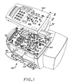
- FIG. 1 is an isometric view of an exemplary multi-function office machine 50 embodying this invention.
- This machine in a generic platform provides scanning, printing, copying and faxing functions.
- a document feed guide 52 is provided at the top rear side of the machine, for feeding documents to be scanned or faxed.
- An input paper/media tray 54 is provided at the lower front side of the machine.
- An output tray is provided by pull-out wire loop 56, to receive output from the machine.
- the functions of the machine are controlled by the control panel subassembly 60 which includes a circuit board (not visible in FIG. 1) which carries machine controllers such as a microprocessor, memory and the like.
- the control panel subassembly 60 includes a top housing structure 62 which cooperates with the circuit board to provide structural support and protection for the various key-switches, display and light indicators which are electrically and mechanically coupled to the circuit board.
- the subassembly 60 includes an LCD panel 64 which displays information to the user.
- Keycap array 68 includes exemplary keycap 68A and is a telephone-type keypad allowing the user to enter information and to dial telephone numbers for the faxing function.
- the functions of the other key-switches/keycaps and indicator lights are as follows, for this exemplary embodiment.
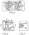
- the machine 50 further includes a control panel cover 150 for assembly to the control panel 60.
- the control panel cover 150 snap fits onto the control panel, as illustrated in FIGS. 2 and 3.
- one edge fastener 152 of the cover 150 is shown, which is received in a corresponding receptor 110 of the control panel 60.
- the fastener includes four barbed tabs arranged concentrically about a center axis, including tabs 152A, 152B and 152C, formed integrally with the cover 150, e.g. from injection molded plastic.
- the diameter of the fastener 152 is slightly larger than the opening 110A, which is defined by chamfered walls 110B.
- the fastener 152 comes into contact with the chamfered wall, and the barbed ends of the tabs (e.g. tabs 152A-152C) are compressed, bending inwardly, allowing insertion of the fastener into the opening 110A.
- the underside of the chamfered wall 110B forms a shoulder 110C against which the barbed ends expand and abut against, as shown in FIG. 3, holding the cover in place.
- a protruding tab 152D controls the depth of insertion of the fastener 152 into the receptor 110, and its length cooperates with the length of the tabs 152A, 152B to securely hold the cover in place. Seven of the fasteners 152 are employed in this embodiment, at the corners and other locations of the cover, and engage with corresponding receptors in the control panel assembly 60.
- the user-activated functions are selected by activation of membrane switches comprising the control panel subassembly 60.
- membrane switches comprising the control panel subassembly 60.
- the user-activated make-break circuits are referred to herein as "key-switches.”
- the user actuates the key-switches through keycaps, the keycaps being pressed by the user to apply force to the underlying membrane key-switch on the control panel subassembly.
- keycaps reside with the control panel assembly 60 and protrude above the surface of the structure 62 by a sufficient distance to extend through corresponding openings formed in the panel cover 150, to be accessible for manual activation by the machine user.
- this type of keycap include the keycap 68A, the power keycap 86 and the start keycap 104.
- Other keycaps reside with the cover. Examples of this type include the one touch speed dial keycaps comprising array 200 (FIG. 8) which contact the key-switch array 70, the copy quality reduce/enlarge keycap 156 (FIG. 8) which contacts key-switch 96, and the scan keycap 202 (FIG. 8) which contacts key-switch 106.
- keycaps for a selected group or set of the key-switches can be omitted from the panel cover, so that the corresponding key-switches on the subassembly 60 are not accessible to the machine user with the panel cover in place.
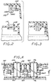
- FIGS. 4 and 5 illustrate one exemplary technique for holding keycaps in the panel cover 150 to provide a cover-mounted means to actuate the membrane key-switch on the control panel subassembly 60.
- FIG. 4 shows the two key-switches 94 and 96 mounted in the control panel 60.
- Corresponding keycaps 154, 156 are supported by the cover 150 for movement to engage the key-switches 94, 96. While movement is permitted to engage the key-switches, the keycaps are constrained by mounting structures from becoming disassembled from the cover.
- the keycaps 154, 156 protrude through respective openings 158, 160 in the cover 150, with side walls 162, 164 defining the openings.
- the side walls 162, 164 have a slight taper, as do the keycaps 154, 156.
- Integrally formed with the keycaps into a keycap array 170 are living hinges 154A, 156A, which extend between the keycaps and a frame portion 172 of the structure 170.
- the array 170 can be formed from a plastic material through injection molding processes.
- the keycaps 154, 156 are respectively formed of crossed ribs structures 154B, 154C and 156B, 156C (FIG. 5).
- the array 170 is aligned to the underside of the cover 150 by attachment pins 180A, 182A extending from bosses 180, 182, and by fastener 184 protruding from the undersurface of the cover and engaging receptacle 186 of the keycap array 170.
- the living hinges such as hinges 154A, 156A allow the keycaps to be depressed downwardly into engagement with the key-switches 94, 96.
- FIGS. 6 and 7 illustrate a light pipe arrangement for conducting light emitted from a light source such as an LED mounted on the control panel through an opening formed in the cover.
- a light pipe structure 190 is attached to the cover by a barbed tab 194 protruding from the underside of the cover, and the light pipe has a tip extending into hole 192 formed in the cover.
- the indicator light 92 generates light energy which is passed into the light pipe and through the cover hole, and is visible to a user.
- the light pipe structure 190 can be fabricated of a transparent plastic material. The attachment of the light pipe structure 190 to the cover 150 is by a snap fit.
- FIG. 8 is a top plan view of the control panel cover 150 in the condition when it is not assembled to the machine 50.
- This particular cover is adapted for a first machine configuration, wherein all the key-switches and indicator lights on the control panel assembly are available to the user once the cover is attached to the control panel assembly.
- the cover carries a speed dial keycap array 200, which enables the user to actuate the speed dial key-switches 70 on the control panel assembly, as well as the keycaps 154, 156 described above, and keycap 202.
- the keycap 202 is for making contact with the key-switch 106 on the control panel subassembly.
- the cover 150 configures the machine 50 to a configuration in which a first set of user-accessible function key/switches and light indicators available on the control panel 60 are fully functional after assembling the cover onto the control panel assembly.
- the first set provides a configuration of full functionality of all user-accessible machine functions.
- FIG. 9 illustrates an exemplary second control panel cover 150' which is adapted for a second machine configuration.
- This cover is fabricated without the keycap array 200, and without corresponding openings formed in the cover.
- the cover 150' is fabricated without openings for the keycaps 154, 156 and 202 of the cover 150.
- the alternative cover can omit a light indicator function by not providing an opening through which light from an indicator light is passed to the user.
- the second cover 150' can omit the light indicator opening for indicator light 92 as well as the light pipe structure 190 of the cover 150, so that light from light source 92 is not visible to the user once the cover is installed, even though the light source can be fully functional.
- the cover 150' configures the machine 50 to a second configuration wherein a second set of switches is available to the user, and the functions provided by key-switches 94, 96, 106, as well as speed dial key-switches 70 are not available to the user.
- first and second cover embodiments are exemplary as to the number and functions of the key, switch or indicator light functions which can be omitted from a particular configuration.
- particular embodiments can employ three or more different covers, all for assembly to a common control panel, for providing the capability of providing three or more different product configurations.
- the respective panel covers 150, 150' are fabricated of a thermoplastic material using an injection molding process.
- other fabrication techniques could alternatively be employed.
- the configuration process can be enhanced by some type of electronic part configuration, wherein the particular machine is programmed electronically to a particular configuration and certain functions are disabled from operation for a given configuration.
- This electronic configurability can disable certain function, e.g. disable from operation a switch function or an indicator light.
- a control panel cover selection will also be used in accordance with the invention to provide late point configuration of the generic machine.
Abstract
Description
- This invention relates to office equipment, and more particularly to a technique for configuring a universally configurable piece of office equipment to a particular product configuration wherein certain features or performance capabilities are added or disabled, by providing a particular control panel cover for each product configuration and a universal control panel assembly.
- Office equipment such as printers, scanners, copiers and facsimile machines are in common use. Recently, new types of office equipment have been introduced, which combine functions of various machines into a single piece of equipment. These multi-purpose machines include, for example, the "OfficeJet" series of machines marketed by Hewlett-Packard Company, which includes functions of a printer and a facsimile machine, and as well those functions of a scanner and a copier. This invention will be described in the exemplary context of such multi-purpose machines, although the invention is not limited in application to such machines.
- Manufacturers of office machines for today's globalized marketplace will typically manufacture one machine for many different countries. The product is then localized for a given country or language requirement. Localization refers to the process of having the product text messages in the local language into which the product is to be sold and ultimately used. Typically the product is built with any messages to be displayed on a product display stored in memory in the various languages. During the localization process, the machine is set up to use the particular language for displayed messages, and to provide the messages in the appropriate language for any text messages appearing on the machine housing including control panels. Thus, for example, the control panel may have a "Start" keycap which needs to be labeled in the appropriate language. A label is placed on the control panel in the appropriate language during the localization process. This of course is time consuming and adds to the cost of production, and would cause a need for a different control panel for each language. Another technique is to provide a snap-on cover for the control panel of the machine, the cover having the requisite language text already included on the cover.
- Manufacturers of office machines, such as the multi-purpose equipment, can construct a particular type of machine to have a range of performance and operational features or options, i.e. a universal machine, which can be configured as different product models. Configuration refers to the adaptation of the product to add or remove performance and/or features from the universal machine to meet customer needs. In the past, the factory typically made certain quantities of the product having the various options; i.e. the configuration was done at the factory. This has the disadvantage of added inventory for the various product configurations, and added cost in product manufacture, since different product configurations are built, as compared to building only a single universal machine.
- A method is described for late point configuration of a multi-configurable office machine, comprising the following steps:
- providing the multi-configurable office machine having a control panel with a plurality of user-activated key-switches for controlling functions of the office machine;
- providing a plurality of types of covers for assembly to the control panel, wherein a first cover type provides user access to a first set of the key-switches when the cover is installed on the control panel, and a second cover type provides user access to a second set of the key-switches when the cover is installed on the control panel;
- selecting one of the plurality of types of covers for configuring the machine to a configuration type having functions provided by the corresponding set of key-switches; and
- installing a cover of the selected type on the control panel to configure the machine to the configuration type.
-
- In accordance with a further aspect, the control panel further has one or more indicator light sources for providing one or more indicator functions. The first cover type further includes an opaque structure have one or more regions transparent to light emitted from corresponding light sources. The second cover type includes an opaque structure for blocking light from one or more of the light sources when installed on the control panel.
- In accordance with another aspect of the invention, a multi-configurable office machine is described, which includes a control panel subassembly having a plurality of user-activated key-switches for controlling functions of the office machine. A first control panel cover is adapted for installation on the control panel subassembly, the first cover comprising a first cover structure providing user access to a first set of the key-switches when the first cover is installed on the control panel subassembly. A second control panel cover is adapted for installation on the control panel subassembly, the second cover comprising a second cover structure providing user access to a second set of the key-switches when the second cover is installed on the control panel subassembly. Thus, by installing a selected one of the panel covers, different groups of the key-switches are accessible to the user, thereby configuring the machine to a first configuration or a second configuration.
- These and other features and advantages of the present invention will become more apparent from the following detailed description of an exemplary embodiment thereof, as illustrated in the accompanying drawings, in which:
- FIG. 1 is an isometric view of a multi-purpose office machine embodying the invention, showing a first control panel cover in exploded view relative to the control panel subassembly.
- FIG. 2 is a cross-sectional exploded view of a portion of the control panel cover and the control panel subassembly, taken along line 2-2 of FIG. 1.
- FIG. 3 is a cross-sectional view of the portion of the control panel cover and the control panel subassembly of FIG. 2, showing the elements snap-fitted into assembled position.
- FIG. 4 is a cross-sectional view taken along line 4-4 of FIG. 1.
- FIG. 5 is a bottom view of a portion of the structure illustrated in FIG. 4.
- FIG. 6 is a cross-sectional view taken along line 6-6 of FIG. 1.
- FIG. 7 is a bottom view of a portion of the structure illustrated in FIG. 6.
- FIG. 8 is a top plan view of a first control panel cover for assembly to the control panel subassembly of the machine of FIG. 1.
- FIG. 9 is a top plan view of a second control panel cover for assembly to the control panel subassembly of the machine of FIG. 1.
-
- An exemplary embodiment of the invention is described with reference to configuring a multi-purpose office machine, which includes a control panel subassembly and a control panel cover which snap fits onto the subassembly. The control panel subassembly includes various key-switch controls and light indicators. The key-switch controls allow the user to control various functions of the machine, and input commands and data. The light indicators convey information to the user, such as status of various functions and warning/error indications. The configuration process typically requires that a second product configured from the generic product and with a lesser number of features have less access to key-switch controls and light indicators than a first product with a greater number of features. In the past, the solution was for the factory to make certain quantities of product having the various options, i.e. the configuration was done in the factory, and this required having a different control panel assembly for each type of product.
- In accordance with the invention, the generic or universal machine is constructed with a generic control panel subassembly, which has all the keycaps and light-pipe circuitry and electronics needed for all configurations of all products. Configuration is achieved by installing a custom control panel cover for a particular configuration onto the generic control panel assembly. If a particular key-switch or light-pipe is not needed for a particular configuration, then the custom cover does not provide a keycap for the key-switch or light-pipe for the light source, but instead covers it over. By having keycaps and light-pipes snap into the custom cover, or alternatively into the generic control panel subassembly, late point configuration is made possible. Also, by having one generic control panel assembly which is used on multiple products, production volume for the generic panel assembly is increased, and cost is therefore reduced. At the same time, the need to design control panel subassemblies for the various product options is eliminated. Moreover, configuration can be accomplished after factory assembly of the machine, e.g. after shipment to a distribution center location, a retail establishment, or even by the user.
- FIG. 1 is an isometric view of an exemplary
multi-function office machine 50 embodying this invention. This machine in a generic platform provides scanning, printing, copying and faxing functions. Adocument feed guide 52 is provided at the top rear side of the machine, for feeding documents to be scanned or faxed. An input paper/media tray 54 is provided at the lower front side of the machine. An output tray is provided by pull-outwire loop 56, to receive output from the machine. The functions of the machine are controlled by thecontrol panel subassembly 60 which includes a circuit board (not visible in FIG. 1) which carries machine controllers such as a microprocessor, memory and the like. Thecontrol panel subassembly 60 includes a top housing structure 62 which cooperates with the circuit board to provide structural support and protection for the various key-switches, display and light indicators which are electrically and mechanically coupled to the circuit board. Thus, for example, thesubassembly 60 includes an LCD panel 64 which displays information to the user.Keycap array 68 includesexemplary keycap 68A and is a telephone-type keypad allowing the user to enter information and to dial telephone numbers for the faxing function. The functions of the other key-switches/keycaps and indicator lights are as follows, for this exemplary embodiment. - 70
- Speed Dialing, One-touch key-switches
- 72
- Indicator light - warning/error light
- 74
- Indicator light - Telephone line hookup
- 76
- Menu function keycaps
- 78
- Right keycap
- 80
- Left keycap
- 82
- Enter
- 84
- Lighter/darker
- 86
- Power keycap (on/off)
- 87
- Indicator light - power on
- 88
- Speed Dial (facsimile function)
- 90
- Auto answer (facsimile function)
- 92
- Indicator light - auto answer active
- 94
- Copy quality (photocopy function)
- 96
- Reduce/enlarge (photocopy function)
- 98
- Redial/pause (facsimile function)
- 100
- Color resolution (facsimile function)
- 102
- Color copy (photocopy function)
- 104
- Start
- 106
- Scan
- 108
- Black copy
- The
machine 50 further includes acontrol panel cover 150 for assembly to thecontrol panel 60. Thecontrol panel cover 150 snap fits onto the control panel, as illustrated in FIGS. 2 and 3. Here, oneedge fastener 152 of thecover 150 is shown, which is received in acorresponding receptor 110 of thecontrol panel 60. The fastener includes four barbed tabs arranged concentrically about a center axis, includingtabs cover 150, e.g. from injection molded plastic. The diameter of thefastener 152 is slightly larger than theopening 110A, which is defined bychamfered walls 110B. As the cover is pushed onto the control panel, thefastener 152 comes into contact with the chamfered wall, and the barbed ends of the tabs (e.g. tabs 152A-152C) are compressed, bending inwardly, allowing insertion of the fastener into theopening 110A. The underside of the chamferedwall 110B forms a shoulder 110C against which the barbed ends expand and abut against, as shown in FIG. 3, holding the cover in place. A protrudingtab 152D controls the depth of insertion of thefastener 152 into thereceptor 110, and its length cooperates with the length of thetabs 152A, 152B to securely hold the cover in place. Seven of thefasteners 152 are employed in this embodiment, at the corners and other locations of the cover, and engage with corresponding receptors in thecontrol panel assembly 60. - In accordance with an aspect of the invention, different panel covers are provided to configure the
machine 50 to different configurations. - In this exemplary embodiment, the user-activated functions are selected by activation of membrane switches comprising the
control panel subassembly 60. Of course, the invention is not limited to use of membrane switches as a make-break circuitry, and other circuitry could alternatively be employed. The user-activated make-break circuits are referred to herein as "key-switches." In this exemplary embodiment, the user actuates the key-switches through keycaps, the keycaps being pressed by the user to apply force to the underlying membrane key-switch on the control panel subassembly. - It is noted that some of the keycaps reside with the
control panel assembly 60 and protrude above the surface of the structure 62 by a sufficient distance to extend through corresponding openings formed in thepanel cover 150, to be accessible for manual activation by the machine user. Examples of this type of keycap include thekeycap 68A, the power keycap 86 and thestart keycap 104. Other keycaps reside with the cover. Examples of this type include the one touch speed dial keycaps comprising array 200 (FIG. 8) which contact the key-switch array 70, the copy quality reduce/enlarge keycap 156 (FIG. 8) which contacts key-switch 96, and the scan keycap 202 (FIG. 8) which contacts key-switch 106. Alternatively, for a different control panel embodiment, keycaps for a selected group or set of the key-switches can be omitted from the panel cover, so that the corresponding key-switches on thesubassembly 60 are not accessible to the machine user with the panel cover in place. - FIGS. 4 and 5 illustrate one exemplary technique for holding keycaps in the
panel cover 150 to provide a cover-mounted means to actuate the membrane key-switch on thecontrol panel subassembly 60. FIG. 4 shows the two key-switches control panel 60.Corresponding keycaps cover 150 for movement to engage the key-switches keycaps respective openings cover 150, withside walls 162, 164 defining the openings. In this exemplary embodiment, theside walls 162, 164 have a slight taper, as do thekeycaps hinges 154A, 156A, which extend between the keycaps and a frame portion 172 of the structure 170. The array 170 can be formed from a plastic material through injection molding processes. Thekeycaps ribs structures cover 150 byattachment pins 180A, 182A extending frombosses 180, 182, and byfastener 184 protruding from the undersurface of the cover and engagingreceptacle 186 of the keycap array 170. The living hinges such as hinges 154A, 156A allow the keycaps to be depressed downwardly into engagement with the key-switches - One or more of the indicator lights such as 72 or 87 are visible in the
panel cover 150 through a corresponding opening. For an alternate panel cover for a different configuration, the cover opening for one or more of these indicator lights can be omitted, so that the indicator light is covered over and not visible to the machine user. FIGS. 6 and 7 illustrate a light pipe arrangement for conducting light emitted from a light source such as an LED mounted on the control panel through an opening formed in the cover. Here alight pipe structure 190 is attached to the cover by a barbed tab 194 protruding from the underside of the cover, and the light pipe has a tip extending intohole 192 formed in the cover. Theindicator light 92 generates light energy which is passed into the light pipe and through the cover hole, and is visible to a user. Thelight pipe structure 190 can be fabricated of a transparent plastic material. The attachment of thelight pipe structure 190 to thecover 150 is by a snap fit. - FIG. 8 is a top plan view of the
control panel cover 150 in the condition when it is not assembled to themachine 50. This particular cover is adapted for a first machine configuration, wherein all the key-switches and indicator lights on the control panel assembly are available to the user once the cover is attached to the control panel assembly. Thus, in this example, the cover carries a speeddial keycap array 200, which enables the user to actuate the speed dial key-switches 70 on the control panel assembly, as well as thekeycaps keycap 202. Thekeycap 202 is for making contact with the key-switch 106 on the control panel subassembly. Thus, thecover 150 configures themachine 50 to a configuration in which a first set of user-accessible function key/switches and light indicators available on thecontrol panel 60 are fully functional after assembling the cover onto the control panel assembly. In this example, the first set provides a configuration of full functionality of all user-accessible machine functions. - FIG. 9 illustrates an exemplary second control panel cover 150' which is adapted for a second machine configuration. This cover is fabricated without the
keycap array 200, and without corresponding openings formed in the cover. Similarly, the cover 150' is fabricated without openings for thekeycaps cover 150. Further, the alternative cover can omit a light indicator function by not providing an opening through which light from an indicator light is passed to the user. For example, the second cover 150' can omit the light indicator opening for indicator light 92 as well as thelight pipe structure 190 of thecover 150, so that light fromlight source 92 is not visible to the user once the cover is installed, even though the light source can be fully functional. Thus, the cover 150' configures themachine 50 to a second configuration wherein a second set of switches is available to the user, and the functions provided by key-switches switches 70 are not available to the user. - The foregoing first and second cover embodiments are exemplary as to the number and functions of the key, switch or indicator light functions which can be omitted from a particular configuration. In addition, particular embodiments can employ three or more different covers, all for assembly to a common control panel, for providing the capability of providing three or more different product configurations.
- In an exemplary embodiment, the respective panel covers 150, 150' are fabricated of a thermoplastic material using an injection molding process. Of course, other fabrication techniques could alternatively be employed.
- In some embodiments, the configuration process can be enhanced by some type of electronic part configuration, wherein the particular machine is programmed electronically to a particular configuration and certain functions are disabled from operation for a given configuration. This electronic configurability can disable certain function, e.g. disable from operation a switch function or an indicator light. In addition to such electronic configurability, a control panel cover selection will also be used in accordance with the invention to provide late point configuration of the generic machine.
- It is understood that the above-described embodiments are merely illustrative of the possible specific embodiments which may represent principles of the present invention. Other arrangements may readily be devised in accordance with these principles by those skilled in the art without departing from the scope and spirit of the invention.
Claims (13)
- A method for late point configuration of a multi-configurable office machine (50), comprising the following steps:providing the multi-configurable office machine (50) having a control panel (60) with a plurality of user-activated key-switches for controlling functions of the office machine;providing a plurality of types of covers (150, 150') for assembly to the control panel, wherein a first cover type (150) provides user access to a first set of said key-switches when the cover is installed on the control panel, and a second cover type (150') provides user access to a second set of said key-switches when the cover is installed on the control panel;selecting one of said plurality of types of covers for configuring the machine to a configuration type having functions provided by the corresponding set of key-switches; andinstalling a cover of said selected type on said control panel to configure the machine to said configuration type.
- A method according to Claim 1 wherein the control panel (60) further has one or more indicator light sources (72, 87,92) for providing one or more indicator functions, said first cover type (150) further includes an opaque structure having one or more regions transparent to light emitted from corresponding light sources, and said second cover type (150') includes an opaque structure for blocking light from one or more of said light sources when installed on said control panel.
- A method according to any preceding claim, wherein the step of installing said cover of said selected type includes engaging a plurality of fasteners (152) fabricated integrally with said cover with a corresponding plurality of fastener receptacles (110) on said control panel.
- A method according to any preceding claim, wherein the step of providing the multi-configurable office machine includes:assembling the office machine at a factory location, wherein the office machine fabrication is essentially completed except for installation of a cover on said control panel; andshipping the assembled office machine from said factory location to a distribution location,
and wherein the step of installing said cover includes installing the cover at said distribution location. - A method according to any of Claims 1-3, wherein the step of providing the multi-configurable office machine includes:assembling the office machine at a factory location, wherein the office machine fabrication is essentially completed except for installation of a cover on said control panel; andshipping the assembled office machine from said factory location to a retail establishment location,
and wherein the step of installing said cover includes installing the cover at said retail establishment location. - A method according to any of Claims 1-3, wherein the step of providing the multi-configurable office machine includes:assembling the office machine at a factory location, wherein the office machine fabrication is essentially completed except for installation of a cover on said control panel; andshipping the assembled office machine from said factory location to an end user location of said office machine,
and wherein the step of installing said cover includes installing the cover at the end user location. - A method according to any preceding claim, wherein the step of providing a plurality of types of cover includes:providing the first cover type (150) having a first cover carrying at least one keycap (154), said at least one keycap for engaging a corresponding key-switch on the control panel when installed on the control panel;providing the second cover type (150') without at least one keycap corresponding to said at least one keycap (154) of said first cover type, wherein the corresponding key-switch on the control panel is not accessible to the user when the second cover type is installed on the control panel.
- A multi-configurable office machine (50), comprising:a control panel subassembly (60) having a plurality of user-activated key-switches for controlling functions of the office machine;a first control panel cover (150) for installation on the control panel subassembly, the first cover comprising a first cover structure providing user access to a first set of said key-switches when the first cover is installed on the control panel subassembly; anda second control panel cover (150') for installation on the control panel subassembly, the second cover comprising a second cover structure providing user access to a second set of said key-switches when the second cover is installed on the control panel subassembly;
wherein a selected one of said plurality of types of covers configures the machine to a configuration type having functions provided by the corresponding set of key-switches. - A machine according to Claim 8 wherein:the control panel subassembly further comprises one or more indicator light sources (72, 87, 92) for providing one or more indicator functions;said first cover structure (150) is an opaque structure having one or more regions transparent to light emitted from corresponding light sources when installed on the control panel subassembly; andsaid second cover structure (150') includes an opaque structure for blocking light from one or more of said light sources when installed on said control panel subassembly.
- A machine according to Claim 8 or Claim 9, wherein the functions of the office machine including facsimile machine functions, document scanning functions and document copying functions.
- A machine according to any of Claims 8-10, wherein:said first control panel cover (150) includes at least one keycap (154) carried by said first cover structure, said at least one keycap for engaging a corresponding key-switch (94) on the control panel when installed on the control panel;said second control panel cover (150') is devoid of at least one keycap corresponding to said at least one keycap (154) of said first cover, wherein the corresponding key-switch (94) on the control panel is not accessible to the user when the second panel cover is installed on the control panel.
- A kit for configuring an office machine (5) to a particular one of a plurality of functional configurations, comprising:a control panel subassembly (60) having a plurality of user-activated key-switches for controlling functions of the office machine;a first control panel cover (150) for installation on the control panel subassembly, the first cover comprising a first cover structure providing user access to a first set of said key-switches when the first cover is installed on the control panel subassembly; anda second control panel cover (150') for installation on the control panel subassembly, the second cover comprising a second cover structure providing user access to a second set of said key-switches when the second cover is installed on the control panel subassembly;
wherein a selected one of said plurality of types of covers is for configuring the machine to a configuration type having functions provided by the corresponding set of key-switches. - A kit according to Claim 12 wherein:the control panel subassembly (60) further comprises one or more indicator light sources (72, 87, 92) for providing one or more indicator functions;said first cover structure (150) is an opaque structure having one or more regions transparent to light emitted from corresponding light sources when installed on the control panel subassembly; andsaid second cover structure (150') includes an opaque structure for blocking light from one or more of said light sources when installed on said control panel subassembly.
Applications Claiming Priority (2)
| Application Number | Priority Date | Filing Date | Title |
|---|---|---|---|
| US345198 | 1999-06-30 | ||
| US09/345,198 US6111207A (en) | 1999-06-30 | 1999-06-30 | Kit for multi-configurable control panel design for office equipment |
Publications (3)
| Publication Number | Publication Date |
|---|---|
| EP1065686A2 true EP1065686A2 (en) | 2001-01-03 |
| EP1065686A3 EP1065686A3 (en) | 2002-07-17 |
| EP1065686B1 EP1065686B1 (en) | 2004-07-28 |
Family
ID=23353998
Family Applications (1)
| Application Number | Title | Priority Date | Filing Date |
|---|---|---|---|
| EP00109623A Expired - Lifetime EP1065686B1 (en) | 1999-06-30 | 2000-05-05 | Kit for multi-configurable control panel design for office equipment |
Country Status (3)
| Country | Link |
|---|---|
| US (1) | US6111207A (en) |
| EP (1) | EP1065686B1 (en) |
| DE (1) | DE60012431T2 (en) |
Families Citing this family (12)
| Publication number | Priority date | Publication date | Assignee | Title |
|---|---|---|---|---|
| US6669085B1 (en) * | 2002-08-07 | 2003-12-30 | Hewlett-Packard Development Company, L.P. | Making language localization and telecommunications settings in a multi-function device through image scanning |
| DE10260161A1 (en) * | 2002-12-20 | 2004-07-08 | BSH Bosch und Siemens Hausgeräte GmbH | Display device for household appliances |
| US20050007613A1 (en) * | 2003-07-09 | 2005-01-13 | Fritz Terry M. | Imaging system control panel method and apparatus |
| WO2005084201A2 (en) * | 2004-02-25 | 2005-09-15 | Control4 Corporation | A system for remotely controlling an electrical switching device |
| ITTV20040158A1 (en) * | 2004-12-30 | 2005-03-30 | Nice Spa | REMOTE CONTROLLER. |
| JP2006295885A (en) * | 2005-03-14 | 2006-10-26 | Seiko Epson Corp | Operation panel, its manufacturing method, and electronic control device |
| DE102006013937A1 (en) * | 2006-03-16 | 2007-09-27 | Prettl Appliance Systems Gmbh | Control panel assembly for household machines and method for producing a control panel assembly |
| US7715208B2 (en) * | 2006-09-08 | 2010-05-11 | Intel Corporation | Configurable multi-faceted input/output panel |
| US8178802B2 (en) | 2008-07-31 | 2012-05-15 | Electrolux Home Products, Inc. | Unitized appliance control panel assembly and components of the assembly |
| JP5433599B2 (en) * | 2011-02-16 | 2014-03-05 | 京セラドキュメントソリューションズ株式会社 | Image forming apparatus |
| US10470956B2 (en) | 2014-07-25 | 2019-11-12 | Huntleigh Technology Limited | System and method to physically and electronically configure an air mattress system for multiple users |
| CN107331322A (en) * | 2017-03-29 | 2017-11-07 | 宁波方太厨具有限公司 | A kind of operation display interface structure of household electrical appliance |
Citations (3)
| Publication number | Priority date | Publication date | Assignee | Title |
|---|---|---|---|---|
| US4078257A (en) * | 1976-08-23 | 1978-03-07 | Hewlett-Packard Company | Calculator apparatus with electronically alterable key symbols |
| US4092527A (en) * | 1977-01-31 | 1978-05-30 | Texas Instruments Incorporated | Calculator with interchangeable keyset |
| US4119839A (en) * | 1976-11-30 | 1978-10-10 | W & G Instruments, Inc. | Keyboard mask for general-purpose calculator |
Family Cites Families (5)
| Publication number | Priority date | Publication date | Assignee | Title |
|---|---|---|---|---|
| US4066850A (en) * | 1976-06-04 | 1978-01-03 | Ncr Corporation | Keyboard switch assembly having interchangeable cover plate, indicating layer and actuator switch assembly in any operative combination |
| US4158130A (en) * | 1977-05-09 | 1979-06-12 | Ncr Corporation | Interchangeable auxiliary keyboard |
| GB8524843D0 (en) * | 1985-10-09 | 1985-11-13 | Philips Electronic Associated | Telephone instrument |
| JP2715889B2 (en) * | 1993-12-24 | 1998-02-18 | 日本電気株式会社 | Printer with facsimile function |
| US5798715A (en) * | 1996-06-28 | 1998-08-25 | Saperstone; Dorothy Luhr | Method and device for accessing remote control functions |
-
1999
- 1999-06-30 US US09/345,198 patent/US6111207A/en not_active Expired - Fee Related
-
2000
- 2000-05-05 DE DE60012431T patent/DE60012431T2/en not_active Expired - Fee Related
- 2000-05-05 EP EP00109623A patent/EP1065686B1/en not_active Expired - Lifetime
Patent Citations (3)
| Publication number | Priority date | Publication date | Assignee | Title |
|---|---|---|---|---|
| US4078257A (en) * | 1976-08-23 | 1978-03-07 | Hewlett-Packard Company | Calculator apparatus with electronically alterable key symbols |
| US4119839A (en) * | 1976-11-30 | 1978-10-10 | W & G Instruments, Inc. | Keyboard mask for general-purpose calculator |
| US4092527A (en) * | 1977-01-31 | 1978-05-30 | Texas Instruments Incorporated | Calculator with interchangeable keyset |
Also Published As
| Publication number | Publication date |
|---|---|
| EP1065686A3 (en) | 2002-07-17 |
| DE60012431D1 (en) | 2004-09-02 |
| EP1065686B1 (en) | 2004-07-28 |
| US6111207A (en) | 2000-08-29 |
| DE60012431T2 (en) | 2005-08-18 |
Similar Documents
| Publication | Publication Date | Title |
|---|---|---|
| US6111207A (en) | Kit for multi-configurable control panel design for office equipment | |
| US5151696A (en) | Multi-function keyboard for remote control apparatus | |
| JP4610004B2 (en) | Push button mechanism, operation panel, and image forming apparatus | |
| US5763841A (en) | Membrane type keyboard with improved multiple key arrangement | |
| EP2149892B1 (en) | Miniature switch | |
| WO1998029886A1 (en) | Virtual touch screen switch | |
| US7014330B2 (en) | Lighted switch device | |
| US7456369B2 (en) | Push button mechanism, operation panel, and image forming apparatus | |
| EP1208575B1 (en) | Gimbal mounted multifunction button | |
| JP2006295885A (en) | Operation panel, its manufacturing method, and electronic control device | |
| JP5546073B2 (en) | Multi-function control interface | |
| US5826708A (en) | Backlighted dome switch assembly | |
| US5610797A (en) | Control panel apparatus for electronic devices | |
| US5075686A (en) | Switch input device | |
| JP2001155573A (en) | Switch | |
| JP4850888B2 (en) | Button key structure and electronic device | |
| JP3948021B2 (en) | Tact switch | |
| JP2007042431A (en) | Mounting structure of operation button and image forming device equipped with the same | |
| JP2001236164A (en) | Key structure | |
| CN113366392A (en) | Input device and image forming apparatus | |
| JP2000299567A (en) | Fitting structure for push-button train | |
| JP2005339876A (en) | Operation panel | |
| JP2023176907A (en) | Switching device and electronic music instrument | |
| CN117153133A (en) | Button device and electronic equipment | |
| JP2003140805A (en) | Control panel button structure for electronic equipment device |
Legal Events
| Date | Code | Title | Description |
|---|---|---|---|
| PUAI | Public reference made under article 153(3) epc to a published international application that has entered the european phase |
Free format text: ORIGINAL CODE: 0009012 |
|
| AK | Designated contracting states |
Kind code of ref document: A2 Designated state(s): AT BE CH CY DE DK ES FI FR GB GR IE IT LI LU MC NL PT SE |
|
| AX | Request for extension of the european patent |
Free format text: AL;LT;LV;MK;RO;SI |
|
| RAP1 | Party data changed (applicant data changed or rights of an application transferred) |
Owner name: HEWLETT-PACKARD COMPANY, A DELAWARE CORPORATION |
|
| PUAL | Search report despatched |
Free format text: ORIGINAL CODE: 0009013 |
|
| AK | Designated contracting states |
Kind code of ref document: A3 Designated state(s): AT BE CH CY DE DK ES FI FR GB GR IE IT LI LU MC NL PT SE |
|
| AX | Request for extension of the european patent |
Free format text: AL;LT;LV;MK;RO;SI |
|
| 17P | Request for examination filed |
Effective date: 20021009 |
|
| 17Q | First examination report despatched |
Effective date: 20021206 |
|
| AKX | Designation fees paid |
Designated state(s): DE FR GB |
|
| GRAP | Despatch of communication of intention to grant a patent |
Free format text: ORIGINAL CODE: EPIDOSNIGR1 |
|
| GRAS | Grant fee paid |
Free format text: ORIGINAL CODE: EPIDOSNIGR3 |
|
| GRAA | (expected) grant |
Free format text: ORIGINAL CODE: 0009210 |
|
| AK | Designated contracting states |
Kind code of ref document: B1 Designated state(s): DE FR GB |
|
| REG | Reference to a national code |
Ref country code: GB Ref legal event code: FG4D |
|
| REG | Reference to a national code |
Ref country code: IE Ref legal event code: FG4D |
|
| REF | Corresponds to: |
Ref document number: 60012431 Country of ref document: DE Date of ref document: 20040902 Kind code of ref document: P |
|
| ET | Fr: translation filed | ||
| PLBE | No opposition filed within time limit |
Free format text: ORIGINAL CODE: 0009261 |
|
| STAA | Information on the status of an ep patent application or granted ep patent |
Free format text: STATUS: NO OPPOSITION FILED WITHIN TIME LIMIT |
|
| 26N | No opposition filed |
Effective date: 20050429 |
|
| PGFP | Annual fee paid to national office [announced via postgrant information from national office to epo] |
Ref country code: FR Payment date: 20070517 Year of fee payment: 8 |
|
| PGFP | Annual fee paid to national office [announced via postgrant information from national office to epo] |
Ref country code: DE Payment date: 20080630 Year of fee payment: 9 |
|
| PGFP | Annual fee paid to national office [announced via postgrant information from national office to epo] |
Ref country code: GB Payment date: 20080529 Year of fee payment: 9 |
|
| REG | Reference to a national code |
Ref country code: FR Ref legal event code: ST Effective date: 20090119 |
|
| PG25 | Lapsed in a contracting state [announced via postgrant information from national office to epo] |
Ref country code: FR Free format text: LAPSE BECAUSE OF NON-PAYMENT OF DUE FEES Effective date: 20080602 |
|
| GBPC | Gb: european patent ceased through non-payment of renewal fee |
Effective date: 20090505 |
|
| PG25 | Lapsed in a contracting state [announced via postgrant information from national office to epo] |
Ref country code: GB Free format text: LAPSE BECAUSE OF NON-PAYMENT OF DUE FEES Effective date: 20090505 |
|
| PG25 | Lapsed in a contracting state [announced via postgrant information from national office to epo] |
Ref country code: DE Free format text: LAPSE BECAUSE OF NON-PAYMENT OF DUE FEES Effective date: 20091201 |