EP1065504A1 - Automatic multi-reactor apparatus and method for assessing catalysts with on-line analysis without liquid/gas separation - Google Patents
Automatic multi-reactor apparatus and method for assessing catalysts with on-line analysis without liquid/gas separation Download PDFInfo
- Publication number
- EP1065504A1 EP1065504A1 EP00401455A EP00401455A EP1065504A1 EP 1065504 A1 EP1065504 A1 EP 1065504A1 EP 00401455 A EP00401455 A EP 00401455A EP 00401455 A EP00401455 A EP 00401455A EP 1065504 A1 EP1065504 A1 EP 1065504A1
- Authority
- EP
- European Patent Office
- Prior art keywords
- reactors
- effluent
- analysis
- reaction
- distribution
- Prior art date
- Legal status (The legal status is an assumption and is not a legal conclusion. Google has not performed a legal analysis and makes no representation as to the accuracy of the status listed.)
- Withdrawn
Links
Images


Classifications
-
- G—PHYSICS
- G01—MEASURING; TESTING
- G01N—INVESTIGATING OR ANALYSING MATERIALS BY DETERMINING THEIR CHEMICAL OR PHYSICAL PROPERTIES
- G01N31/00—Investigating or analysing non-biological materials by the use of the chemical methods specified in the subgroup; Apparatus specially adapted for such methods
- G01N31/10—Investigating or analysing non-biological materials by the use of the chemical methods specified in the subgroup; Apparatus specially adapted for such methods using catalysis
-
- Y—GENERAL TAGGING OF NEW TECHNOLOGICAL DEVELOPMENTS; GENERAL TAGGING OF CROSS-SECTIONAL TECHNOLOGIES SPANNING OVER SEVERAL SECTIONS OF THE IPC; TECHNICAL SUBJECTS COVERED BY FORMER USPC CROSS-REFERENCE ART COLLECTIONS [XRACs] AND DIGESTS
- Y10—TECHNICAL SUBJECTS COVERED BY FORMER USPC
- Y10T—TECHNICAL SUBJECTS COVERED BY FORMER US CLASSIFICATION
- Y10T436/00—Chemistry: analytical and immunological testing
- Y10T436/24—Nuclear magnetic resonance, electron spin resonance or other spin effects or mass spectrometry
Definitions
- the present invention relates to an automatic test apparatus multi chemical reaction reactors in the possible presence of a catalyst.
- This apparatus operating under high pressure and high temperature includes an online product analysis system reaction and an elaborate automation system. Rapid assessment and simultaneous several sets of operating conditions thus allows to acquire data on the progress of the reaction and on the performance of solid catalysts.
- the online analysis is carried out on all the products leaving the reactors without prior separation of these into two liquid fractions and carbonated. This is possible thanks to precise temperature control and total and partial pressures of the products leaving the reactors, that allows the fitting. It is possible, with this apparatus, to carry out catalytic tests with hydrocarbon molecules whose number of carbon atoms can vary within a wide range (from 1 to 20 per example).
- the advanced automation of the assembly makes it possible to carry out simultaneous cycles of all reactors without operator intervention.
- the solid catalysts are used in the form of beads, of extrudates or powder of variable particle size.
- the quantities of catalysts used in these pilot plants are generally between a few grams to a few tens or hundreds of grams. These quantities are relatively large and can constitute a limitation on the use of these pilot installations.
- the quantities of catalytic solid available for testing are quite often reduced (less than one gram) and the number of variants solid catalyst can be important. It follows that all available samples are not necessarily tested.
- reactors The most isothermal possible operation is sought for reactors. In general, this is achieved by placing the reactor in an oven consisting of several independently regulated temperature zones (document US-5770154).
- the dimensions of the reactors also make the object of much attention.
- the length to diameter of the catalytic bed is mostly chosen between 50 and 200 to ensure correct flow of reagents and products through the catalyst, failing which limiting phenomena of diffusion or back mixing disturb measurement of rates progress and performance of the catalyst.
- Catalysts generally require before the reaction phase proper, an activation phase that transforms one or more of their constituents as a truly active element for catalysis. he can be a reduction of oxide under hydrogen in the case of catalysts supported metal or sulfurization in the presence of a sulfur precursor for metal sulfide catalysts. In conventional pilot plants with large dead volumes and significant thermal inertia due to the size ovens, this activation phase is generally long (typically from several hours to several tens of hours).
- the nature of the reagent used depends on the intended application. It could be a pure hydrocarbon such as normal hexane, normal heptane, or cyclo hexane or more or less petroleum cuts heavy or heavier or wider, such as petrol, diesel or distillates from the distillation of crude oils.
- the quantities of reagent consumed depend of course on the size of the reactor and the operating time. But more often than not, performance is calculated from the production of input-output material balances taking place over relatively long periods (from a few hours to several tens of hours). These durations are necessary to collect in sufficient quantity (several liters to several tens of liters) products to establish an accurate material balance.
- the use of molecule pure hydrocarbon, of high manufacturing cost, is not always possible under these conditions.
- the catalyst is likely to know some deactivation.
- the activity of the catalyst is not the same between the start and the end of the material balance, the performances calculated in fine only reflect an average behavior of the catalyst far from the actual evolution of performance over time.
- the distribution means may include at least two input channels and two output channels, at least one conduit in closed loop divided into four sections by four elements shutter ordered; each of said four channels can communicate with a single section so that the entry lanes are linked to two opposite sections and the exit routes linked to the other two sections.
- the distribution means can comprise two conduits in loop and the output channels can communicate with each other two by two so as to constitute a distribution device with four input channels and two exit routes.
- Reactors can have an internal diameter between 0.5 and 3 cm, preferably between 1 and 2 cm, a length between 10 and 50 cm, preferably between 15 and 25 cm.
- the temperature and pressure of the effluents can be controlled between the reactor output and the means of measurement and analysis, including distribution means, so that said effluent is gaseous.
- the method and apparatus according to the invention can advantageously be applied to compare the characteristics of different catalysts used in each of the reactors and / or for determine the optimal conditions for using a catalyst for a determined reaction by varying the parameters of the reaction in each of the reactors.
- Each of the gaseous reagent injection systems (2a to 2d) consists of a pressure regulator-regulator, a safety valve, a pressure sensor and a mass flow regulator.
- the gaseous reactant is most often hydrogen.
- the pressure regulator allows to maintain a constant pressure at the inlet of the reactor (variable between 0 and 1.8 10 7 Pa in relative) from the available supply pressure.
- the flow range provided by the mass regulator extends from 5 to 500 l / h with a relative accuracy of 1%.
- These regulators can be, for example, the 5850E models marketed by the BROOKS brand.
- the liquid reagent is injected into each reactor by means of a pump (1a to 1d) which can be of the piston type with a total volume of at least 500 cm 3 such as, for example, pumps 500D of the brand ISCO.
- a pump (1a to 1d) which can be of the piston type with a total volume of at least 500 cm 3 such as, for example, pumps 500D of the brand ISCO.
- This type of pump makes it possible to inject very smoothly at high pressure and with great precision very small liquid flow rates (between 0.05 and 100 cm 3 / h). If the viscosity at room temperature of the reagent is not sufficient to ensure correct injection, this pump will be fitted with a system allowing it to be heated to moderate temperature (50 to 120 ° C).
- the feed pot 10 of the pump 1a (or 1b, 1c, 1d) and the lines of circulation of the reagent between the charge pot 10, the pump and the reactor must be heated for the liquid reagents of insufficient viscosity at room temperature.
- the liquid and gaseous reactants are mixed upstream of the reactor.
- the reactors used or micro-reactors have an internal diameter between 0.5 and 3 cm, preferably between 1 and 2 cm for a length between 10 and 50 cm, preferably between 15 and 25 cm. They are positioned vertically in an oven. Meaning flow of reagents can be ascending or descending. These reactors are made of refractory steel (for example of the Inconel type 625).
- the cylindrical catalyst bed is located in their central part, it contains between 0.1 and 10 g of catalyst. This bed is preceded by a bed of inert material (eg silicon carbide) likewise particle size as the catalyst whose utility is to ensure the preheating and vaporization of reagents.
- These reactors are equipped axially of thermocouples of small diameter (for example 0.5 mm) to measure the temperature at different points along the axis longitudinal.
- the heating furnace of these reactors consists of at least two (preferably four) independent zones relative to the temperature regulation.
- the first zone corresponds to the zone of preheating and vaporization of the reagents, the second in a catalytic bed.
- the presence of different individually regulated zones guarantees a isothermal operation of the reactor along its longitudinal axis.
- the system (4a to 4d) located at the outlet of each of the reactors is consisting of a pre-expansion element and an injection (11a to 11d) to controlled flow of diluent gas in the various product streams reaction (e.g. hydrogen or helium).
- the elements (4a to 4d), the distribution means, or selection system, (5) and the lines circulation of products connecting the reactors (3a to 3d) to the analyzer (6) are maintained at pressure and temperature so that the effluent is gas for a good analysis of the constituents.
- the element of pre-relaxation low internal volume overflow type lowers the pressure of the mixture of reaction products.
- Pressure relief atmospheric reaction effluents is provided by the complete expansion (7a) and (7b) located respectively after the valve selection (5) and the analyzer (6).
- the means of distribution has as much of inputs that there are reactors and two outputs 12 and 11, one towards the analyzer, the other towards an evacuation after expansion.
- a reactive mixture of hydrogen and paraffinic hydrocarbons containing 11 to 16 carbon atoms (at a rate of 5 moles of hydrogen per mole of hydrocarbons) is transformed at 380 ° C and 100 bars with a rate of conversion to lighter hydrocarbons of about 50%.
- the pressure is pre-expanded to 60 bars, the temperature maintained at 230 ° C and diluent gas is injected at the outlet of the reactor.
- the volume flow of this injection is 20 times greater than the flow of hydrogen mixed at the inlet of the reactor with reactive hydrocarbons. Under these conditions, the quality of the chromatographic analysis is correct. All of the reaction products remain in the gaseous state and the sample injected into the chromatographic analyzer is representative reaction products.
- the distribution means (5) comprise a set of valves which allows switching of the flows leaving the reactors towards the analyzer (6) or to a direct expansion system at atmospheric pressure (7a). AT a given instant in the course of the measurement cycles, the output channel of a reactor is switched to track 12 of the analyzer, the other tracks then being switched together towards track 11 towards complete expansion direct.
- These distribution means 5 are illustrated by FIGS. 4a, 4b, 4c, and 4d.
- Figure 4a explains the principle of the selector valve, which can be 2, 4, 6, ..., 2n, input channels and two output channels.
- the two ways of outputs are referenced 20 and 21. In the case shown here, that is 6 channels of inputs, these are referenced A, B, C, D, E, and F.
- the reference 22 designates a sealing element of a conduit, for example a needle cooperating with a conical seat, activated by a piston-type operator pneumatic or hydraulic.
- the design of this valve is based on one, or more closed loop conduits (23, 24, 25); Each loop is divided into four sections of conduits: 23a, 23b, 23c, 23d; 24a, 24b, 24c, 24d; 25a, 25b, 25c, 25d.
- Each section is delimited by a closure element 22.
- valve selection will include at least two loops, the conduits of outputs are connected together, for example by conduits 26, 27, as shown in Figure 4a.
- a selection valve of this type allows the use of elements shutter 22, for example from the brand NOVA SWISS, which can withstand both high pressure and high temperature, as this is the case downstream of the reactors.
- all of the conduits can be designed to constitute a minimum dead volume, which is essential for the quality of the measurements and comparisons between reaction cycles.
- FIG. 4b shows a side view of a selection valve comprising a casing 30 containing a block 31 in which the passage conduits of the effluent has been drilled.
- References 32a, b, c and d ( Figure 4c) denote pneumatic operators who actuate the shutter elements and sealing of the different sections of conduits.
- Space 34 is full of a thermal insulating material.
- FIG. 4b represents a valve with two duct loops, i.e. according to the description above, at four input channels (for reactors 3a, 3b, 3c and 3d) and two input channels exit. Note the staggered arrangement of the pneumatic operators so that the distance between the two planes containing the two loops of ducts is minimal. Thus, the length of the internal conduits (26, 27) is reduced, which decreases the dead volumes.
- Figure 4c is a section along the plane AA ( Figure 4b).
- the fourth sections of conduits are made by four non-opening holes made in block 31.
- the inlet openings (35a, b, c, d) are machined from so as to receive the needle rod of the closure element and gaskets and seal packings.
- the linings waterproofing can be chosen in PEEK (polyetheretherketone).
- Holes 36 and 37 in block 31 are used to place heating and / or control elements.
- References 38 and 39 indicate the conduits connecting the sections of loops at the two outputs of the selection valve.
- FIG. 4d is a view of the section CC through the plane containing the second loop of conduits.
- the structure is identical to that of the first loop illustrated in Figure 4c, except that the elements sealing and sealing are arranged in another direction (at 90 degrees) so that operators 33a, b, c d are staggered by compared to operators 32a, b, c, d.
- the complete expansion systems (7a) and (7b) can be, for example, models of the TESCOM brand dome outlet.
- the analyzer (6) allows detailed analysis of the reaction products chemical.
- This analyzer is equipped with a sampling valve sample these products.
- This valve for example brand VALCO, is placed under the same temperature and pressure conditions as the systems (4a to 4d) and (5).
- This analyzer can be a gas chromatograph, i.e. one or more capillary chromatographic columns or not separating the products of reaction by difference in retention time.
- This analyzer can be by example a 5890 model of HEWLETT PACKARD brand or GC2000 brand THERMO QUEST.
- the command and control system (8) manages all of the regulations temperature, pressure, flow, valves and various actuators. This system is built around an S7-400 PLC of the SIEMENS brand and a Intelligence FIX-DEMACS supervision software.
- This control system 8 allows complete cycles of parallel measurement of reactors. Typically these cycles take place completely independently in several successive phases: test pressure of the assembly, purging with an inert gas, activation of the catalyst if necessary, reaction with performance measurement and finally purge of the installation before shutdown.
- An example of a cycle is shown in the figure 2. The course of the cycle is identified by the change in temperature T of the reactor as a function of time H. The circuit is purged with nitrogen from 0 to 0.5 H. The catalyst is activated by injecting a flow rate of 1 l / h at the pressure of 90 b of hydrogen from 0.5 to 5 hours.
- reaction continues for 5 hours at 9 p.m., according to the temperature levels indicated in Figure 2, with injection of a charge nC7 at 1 cm3 / h and hydrogen at 2 l / h. during this cycle of measurement steps M are carried out at regular intervals.
- reaction products are expanded at the reactor outlet to 5.0 10 6 Pa.
- a dilution hydrogen flow rate of 40 l / h is injected at the outlet of each reactor and the temperature of the zones crossed by these reaction products between the reactor output and the analyzer is maintained at 240 ° C.
- analyzes are carried out on each reactors every 6 hours for 180 hours, making a total of more than 120 analyzes.
- the analyzer used is a phase chromatograph gas fitted with a 50 m PONA apolar capillary column length and 0.2 mm in diameter and a flame ionization detector. The areas of the chromatographic peaks are used to calculate the concentrations in the different reaction products (normal hexadecane, isomers of normal hexadecane and hydrocarbons plus light). The conversion of normal hexadecane is calculated from these data.
- the performances are measured for 4 successive stages of increasing temperature: 320, 340, 360 and 370 ° C.
- the duration of each level is 2 hours.
- a 5 th and final temperature hold is performed at 320 ° C so as to judge the eventual deactivation of the catalysts.
- Analyzes are carried out 1 hour 30 minutes after the start of each temperature level.
- the reaction phase is preceded by a sulfurization identical to that of Example 1.
- the settings for temperature, pressure and flow rate of diluent gas at the outlet of the reactors are identical to those of Example 1.
- the activity is represented by the conversion level of the normal reagent hexadecane for a given temperature.
- Selectivities for isomerization reactions of normal hexadecane to iso hexadecane and cracking of normal hexadecane into lighter hydrocarbons are calculated by dividing the yields of isomerization products and cracked products by conversion.
- the apparatus and the method according to the invention therefore makes it possible to rapidly assess, in parallel and with high precision several catalytic solids.
Abstract
Description
La présente invention concerne un appareillage automatique de test multi réacteurs de réaction chimique en présence éventuelle d'un catalyseur. Cet appareillage fonctionnant sous forte pression et haute température, comprend un système d'analyse en ligne des produits de la réaction et un système élaboré d'automatisation. L'évaluation rapide et simultanée de plusieurs jeux de conditions opératoires permet ainsi d'acquérir des données sur l'avancement de la réaction et sur les performances de catalyseurs solides.The present invention relates to an automatic test apparatus multi chemical reaction reactors in the possible presence of a catalyst. This apparatus operating under high pressure and high temperature, includes an online product analysis system reaction and an elaborate automation system. Rapid assessment and simultaneous several sets of operating conditions thus allows to acquire data on the progress of the reaction and on the performance of solid catalysts.
L'analyse en ligne est réalisée sur la totalité des produits sortant des réacteurs sans séparation préalable de ceux-ci en deux fractions liquide et gazeuse. Ceci est possible grâce au contrôle précis de la température et des pressions totales et partielles des produits sortant des réacteurs, que permet l'appareillage. Il est possible, avec cet appareillage, de réaliser des tests catalytiques avec des molécules hydrocarbonées dont le nombre d'atomes de carbone peut varier dans une large gamme (de 1 à 20 par exemple). L'automatisation poussée de l'ensemble permet de réaliser des cycles simultanés de tous les réacteurs sans intervention de l'opérateur.The online analysis is carried out on all the products leaving the reactors without prior separation of these into two liquid fractions and carbonated. This is possible thanks to precise temperature control and total and partial pressures of the products leaving the reactors, that allows the fitting. It is possible, with this apparatus, to carry out catalytic tests with hydrocarbon molecules whose number of carbon atoms can vary within a wide range (from 1 to 20 per example). The advanced automation of the assembly makes it possible to carry out simultaneous cycles of all reactors without operator intervention.
Le développement des procédés industriels de raffinage et de pétrochimie nécessite d'acquérir des données sur les réactions chimiques qui s'y déroulent. Lorsque ces réactions sont catalysées, la recherche et le développement des catalyseurs requis nécessitent d'évaluer les performances de ces derniers. Au laboratoire, ces acquisitions de données et évaluation sont effectuées dans des installations pilotes qui reproduisent à petite échelle les conditions du fonctionnement industriel. The development of industrial refining and petrochemical requires acquiring data on chemical reactions that take place there. When these reactions are catalyzed, research and development of the required catalysts requires assessing the performance of the latter. In the laboratory, these data acquisitions and evaluation are carried out in pilot plants which reproduce on a small scale the conditions of industrial operation.
Il existe de nombreux types d'appareillage permettant de mesurer le degré d'avancement de réactions chimiques ou l'activité de catalyseurs solides. Dans le domaine du raffinage pétrolier et de la pétrochimie, l'étendue des conditions opératoires dans lesquelles s'effectuent ces mesures est la suivante :
- pression comprise entre 1 105 et 3 107 Pa,
- température comprise entre température ambiante et 800°C,
- débits de réactif liquide et/ou gazeux exprimés sous forme de débit volumique horaire par unité de volume de réacteur ou de catalyseur (VVH) compris entre 0,01 et 100 h-1 et par le rapport des débits molaires de gaz (le plus souvent de l'hydrogène) et l'hydrocarbure réactif liquide (H2/HC) compris entre 0,01 et 50.
- pressure between 1 10 5 and 3 10 7 Pa,
- temperature between ambient temperature and 800 ° C,
- liquid and / or gaseous reactant flow rates expressed as hourly volume flow rate per unit of reactor or catalyst volume (VVH) of between 0.01 and 100 h -1 and by the ratio of molar gas flow rates (most often hydrogen) and the liquid reactive hydrocarbon (H 2 / HC) between 0.01 and 50.
Le choix plus précis des conditions opératoires dépend du type de procédé ou de catalyseur considéré. Il peut s'agir, par exemple, de l'une des applications industrielles suivantes : le reformage, l'isomérisation, l'hydrocraquage, l'hydrotraitement, l'hydrogénation sélective, la transformation des aromatiques, ou encore l'oxydation.The more precise choice of operating conditions depends on the type of process or catalyst considered. It could be, for example, one the following industrial applications: reforming, isomerization, hydrocracking, hydrotreatment, selective hydrogenation, transformation of aromatics, or oxidation.
Les catalyseurs solides sont mis en oeuvre sous forme de billes, d'extrudés ou de poudre de granulométrie variable. Les quantités de catalyseurs utilisées dans ces installations pilotes sont généralement comprises entre quelques grammes à quelques dizaines ou centaines de grammes. Ces quantités sont relativement importantes et peuvent constituer une limitation à l'utilisation de ces installations pilotes. En particulier, lors de la recherche ou du développement d'un nouveau catalyseur, les quantités de solide catalytique disponibles pour test sont assez souvent réduites (inférieures au gramme) et le nombre de variantes de solide catalytique peut être important. Il résulte que tous les échantillons disponibles ne sont pas nécessairement testés. The solid catalysts are used in the form of beads, of extrudates or powder of variable particle size. The quantities of catalysts used in these pilot plants are generally between a few grams to a few tens or hundreds of grams. These quantities are relatively large and can constitute a limitation on the use of these pilot installations. In particular, when researching or developing a new catalyst, the quantities of catalytic solid available for testing are quite often reduced (less than one gram) and the number of variants solid catalyst can be important. It follows that all available samples are not necessarily tested.
Le fonctionnement le plus isotherme possible est recherché pour les réacteurs. En général, ceci est obtenu en plaçant le réacteur dans un four constitué de plusieurs zones régulées indépendamment en température (document US-5770154). Les dimensions des réacteurs font également l'objet de beaucoup d'attentions. En particulier, le rapport longueur sur diamètre du lit catalytique est choisi la plupart du temps compris entre 50 et 200 pour garantir un écoulement correct des réactifs et des produits au travers du catalyseur, faute de quoi des phénomènes limitants de diffusion ou de rétro mélange perturbent la mesure des taux d'avancements et de performances du catalyseur.The most isothermal possible operation is sought for reactors. In general, this is achieved by placing the reactor in an oven consisting of several independently regulated temperature zones (document US-5770154). The dimensions of the reactors also make the object of much attention. In particular, the length to diameter of the catalytic bed is mostly chosen between 50 and 200 to ensure correct flow of reagents and products through the catalyst, failing which limiting phenomena of diffusion or back mixing disturb measurement of rates progress and performance of the catalyst.
Les catalyseurs requièrent généralement avant la phase de réaction proprement dite, une phase d'activation qui transforme un ou plusieurs de leurs constituants en élément réellement actif pour la catalyse. Il peut s'agir d'une réduction d'oxyde sous hydrogène dans le cas des catalyseurs métalliques supportés ou encore d'une sulfuration en présence d'un précurseur soufré pour les catalyseurs à base de sulfures métalliques. Dans les installations pilotes classiques qui présentent de grands volumes morts et une inertie thermique importante en raison de la taille des fours, cette phase d'activation est généralement longue (typiquement de plusieurs heures à plusieurs dizaines d'heures).Catalysts generally require before the reaction phase proper, an activation phase that transforms one or more of their constituents as a truly active element for catalysis. he can be a reduction of oxide under hydrogen in the case of catalysts supported metal or sulfurization in the presence of a sulfur precursor for metal sulfide catalysts. In conventional pilot plants with large dead volumes and significant thermal inertia due to the size ovens, this activation phase is generally long (typically from several hours to several tens of hours).
La nature du réactif utilisé (le plus souvent un hydrocarbure ou un mélange d'hydrocarbures) dépend de l'application envisagée. Il peut s'agir d'un hydrocarbure pur comme par exemple du normal hexane, du normal heptane, ou le cyclo hexane ou encore de coupes pétrolières plus ou moins lourdes ou plus ou larges comme par exemple les essences, les gazoles ou distillats issus de la distillation des pétroles bruts. Les quantités de réactif consommées dépendent bien sûr de la dimension du réacteur et de la durée de fonctionnement. Mais le plus souvent, les performances sont calculées à partir de la réalisation de bilans matière entrée-sortie se déroulant sur des périodes relativement longues (de quelques heures à plusieurs dizaines d'heures). Ces durées sont nécessaires pour recueillir en quantité suffisante (plusieurs litres à plusieurs dizaines de litres) les produits pour établir un bilan matière précis. L'utilisation de molécule hydrocarbonée pure, de coût de fabrication élevé, n'est pas toujours possible dans ces conditions.The nature of the reagent used (most often a hydrocarbon or a mixture of hydrocarbons) depends on the intended application. It could be a pure hydrocarbon such as normal hexane, normal heptane, or cyclo hexane or more or less petroleum cuts heavy or heavier or wider, such as petrol, diesel or distillates from the distillation of crude oils. The quantities of reagent consumed depend of course on the size of the reactor and the operating time. But more often than not, performance is calculated from the production of input-output material balances taking place over relatively long periods (from a few hours to several tens of hours). These durations are necessary to collect in sufficient quantity (several liters to several tens of liters) products to establish an accurate material balance. The use of molecule pure hydrocarbon, of high manufacturing cost, is not always possible under these conditions.
Par ailleurs, durant le déroulement de la période d'évaluation du bilan matière qui peut être longue, le catalyseur est susceptible de connaítre une certaine deactivation. L'activité du catalyseur n'étant pas la même entre le début et la fin du bilan matière, les performances calculées in fine ne reflètent que d'un comportement moyen du catalyseur éloigné de l'évolution réelle des performances en fonction du temps.Furthermore, during the course of the balance sheet evaluation period material which can be long, the catalyst is likely to know some deactivation. The activity of the catalyst is not the same between the start and the end of the material balance, the performances calculated in fine only reflect an average behavior of the catalyst far from the actual evolution of performance over time.
Les effluents sortant des réacteurs sont classiquement séparés par détente et refroidissement en deux phases : liquide et gazeuse dont les caractéristiques et compositions sont analysées séparément. Ces opérations de séparation et d'analyses séparées induisent inévitablement des pertes en produits qui diminuent la précision du bilan matière global. Dans certains cas, l'analyse de la totalité des produits n'est pas réalisable en une seule fois sur un analyseur chromatographique unique. Il peut être alors possible de réaliser une analyse en ligne avant séparation liquide/gaz conjointement à une analyse de la fraction gazeuse prélevée après séparation. Ceci permet d'établir des bilans matière précis dans ce cas (document US-5266270).The effluents leaving the reactors are conventionally separated by expansion and cooling in two phases: liquid and gaseous whose characteristics and compositions are analyzed separately. These separation operations and separate analyzes inevitably lead to losses in products which reduce the accuracy of the overall material balance. In some cases, the analysis of all the products is not feasible all at once on a single chromatographic analyzer. he can then be possible to perform an online analysis before separation liquid / gas together with an analysis of the gas fraction sampled after separation. This makes it possible to establish precise material balances in this case (document US-5266270).
L'automatisation des installations pilotes classiques reste assez souvent peu développée. La dimension de ces installations et la prise en compte des règles de sécurité liée à un fonctionnement automatique rendent cette automatisation complexe et onéreuse. En particulier, les conditions opératoires fixant la sévérité à laquelle se déroule la réaction (température ou débit volumique de réactif) sont le plus souvent fixées manuellement par l'opérateur de l'installation.Automation of conventional pilot plants remains fairly often poorly developed. The size of these facilities and the safety rules account linked to automatic operation make this automation complex and expensive. In particular, operating conditions determining the severity of the reaction (temperature or volume flow of reagent) are most often fixed manually by the installation operator.
En résumé, les installations pilotes classiques couramment utilisées pour mesurer l'avancement de réaction chimique et les performances de catalyseurs présentent un certain nombre d'inconvénients, parmi lesquels on peut citer :
- la nécessité de disposer de grande quantité de catalyseur et de réactif,
- la longue durée de mise en régime et d'établissement de bilan matière nécessaire à la détermination des performances,
- les performances reflètent d'un fonctionnement moyen du catalyseur sur une période relativement longue,
- la fréquence de mesure des performances est relativement faible,
- l'automatisation complète du fonctionnement est difficile et onéreuse à réaliser.
- the need to have a large quantity of catalyst and reagent,
- the long period of setting in regime and establishment of material balance necessary for the determination of performances,
- the performances reflect an average operation of the catalyst over a relatively long period,
- the frequency of performance measurement is relatively low,
- full automation of operation is difficult and expensive to achieve.
Ces désavantages font que les installations pilotes classiques sont assez mal adaptées à la sélection rapide et précise ("screening"), parmi de nombreux solides catalytiques, des solides les plus intéressants pour le développement d'un nouveau catalyseur ou l'étude d'une nouvelle réaction.These disadvantages mean that conventional pilot installations are poorly suited to rapid and precise selection ("screening"), among many catalytic solids, the most interesting solids for development of a new catalyst or the study of a new reaction.
Ainsi, la présente invention concerne un appareillage pour effectuer des mesures sur un effluent résultant d'une réaction chimique ayant lieu dans un réacteur contenant un catalyseur. L'appareillage comporte en combinaison:
- au moins deux réacteurs,
- des moyens d'injection d'au moins une charge dans chacun des réacteurs,
- des moyens de distribution pour diriger l'effluent issu d'un des réacteurs vers des moyens d'analyse et de mesure, pendant que les autres effluents issus des autres réacteurs sont dirigés vers une évacuation,
- des moyens de régulation de la pression et de la température dudit effluent dans le circuit compris entre l'aval des réacteurs et l'amont des moyens d'analyse, y compris lesdits moyens de distribution,
- des moyens de contrôle et de commande automatiques de la réaction chimique dans lesdits réacteurs et du cycle d'analyse et de mesure sur l'effluent produit par ladite réaction.
- at least two reactors,
- means for injecting at least one charge into each of the reactors,
- distribution means for directing the effluent from one of the reactors to analysis and measurement means, while the other effluents from the other reactors are directed to an outlet,
- means for regulating the pressure and the temperature of said effluent in the circuit between the downstream of the reactors and the upstream of the analysis means, including said distribution means,
- means for automatic control and command of the chemical reaction in said reactors and of the analysis and measurement cycle on the effluent produced by said reaction.
Dans l'appareillage, les moyens de distribution peuvent comporter au moins deux voies d'entrée et deux voies de sorties, au moins un conduit en boucle fermée divisée en quatre tronçons par quatre éléments d'obturation commandés; chacune desdites quatre voies peut communiquer avec un seul tronçon de façon que les voies d'entrée soient liées à deux tronçons opposés et les voies de sortie liées aux deux autres tronçons.In the apparatus, the distribution means may include at least two input channels and two output channels, at least one conduit in closed loop divided into four sections by four elements shutter ordered; each of said four channels can communicate with a single section so that the entry lanes are linked to two opposite sections and the exit routes linked to the other two sections.
L'appareillage peut comporter quatre réacteurs.The apparatus can comprise four reactors.
Les moyens de distribution peuvent comporter deux conduits en boucle et les voies de sortie peuvent communiquer entre elles deux à deux de façon à constituer un dispositif de distribution à quatre voies d'entrées et deux voies de sorties.The distribution means can comprise two conduits in loop and the output channels can communicate with each other two by two so as to constitute a distribution device with four input channels and two exit routes.
Les réacteurs peuvent avoir un diamètre interne compris entre 0,5 et 3 cm, de préférence entre 1 et 2 cm, une longueur comprise entre 10 et 50 cm, de préférence entre 15 et 25 cm. Reactors can have an internal diameter between 0.5 and 3 cm, preferably between 1 and 2 cm, a length between 10 and 50 cm, preferably between 15 and 25 cm.
L'invention concerne également une méthode d'analyse et de mesure sur un effluent produit par une réaction chimique ayant lieu dans un réacteur contenant un catalyseur, dans laquelle on effectue les étapes suivantes:
- on dispose d'au moins deux réacteurs,
- on injecte au moins une charge dans chacun des réacteurs,
- on effectue une régulation de la température de chaque réacteur,
- on dirige alternativement les effluents issus des réacteurs vers des moyens de mesure et d'analyse par des moyens de distribution,
- on contrôle le déroulement des cycles de réaction, d'analyse et de mesure à l'aide de moyens de contrôle et de commande automatiques.
- we have at least two reactors,
- at least one charge is injected into each of the reactors,
- the temperature of each reactor is regulated,
- the effluents from the reactors are directed in turn to measurement and analysis means by distribution means,
- the progress of the reaction, analysis and measurement cycles is monitored using automatic monitoring and control means.
On peut contrôler la température et la pression des effluents entre la sortie des réacteurs et les moyens de mesure et d'analyse, y compris les moyens de distribution, de façon que ledit effluent soit gazeux.The temperature and pressure of the effluents can be controlled between the reactor output and the means of measurement and analysis, including distribution means, so that said effluent is gaseous.
La méthode et l'appareillage selon l'invention peuvent avantageusement être appliqués pour comparer les caractéristiques de catalyseurs différents employés dans chacun des réacteurs et/ou pour déterminer les conditions optimales de mise en oeuvre d'un catalyseur pour une réaction déterminée en faisant varier les paramètres de la réaction dans chacun des réacteurs.The method and apparatus according to the invention can advantageously be applied to compare the characteristics of different catalysts used in each of the reactors and / or for determine the optimal conditions for using a catalyst for a determined reaction by varying the parameters of the reaction in each of the reactors.
On peut notamment citer les avantages suivants de l'appareillage et de la méthode selon l'invention :
- la mesure automatique d'avancements de réactions chimiques et de performances catalytiques en parallèle sur plusieurs réacteurs,
- l'utilisation de quantité faibles de catalyseur compatible avec une sélection rapide sur un grand nombre d'échantillons,
- une mise en oeuvre isotherme du catalyseur dans les réacteurs,
- la possibilité d'assurer le contrôle des températures et pressions partielles des effluents réacteur pour en permettre l'analyse unique et complète sans séparation en plusieurs fractions,
- la mesure ponctuelle et fréquente des performances réactionnelles et catalytiques,
- une plus grande précision dans la détermination des performances,
- le déroulement complet des cycles de fonctionnement sans intervention de l'opérateur.
- automatic measurement of progress in chemical reactions and catalytic performance in parallel on several reactors,
- the use of small quantities of catalyst compatible with rapid selection on a large number of samples,
- isothermal use of the catalyst in the reactors,
- the possibility of ensuring the control of the temperatures and partial pressures of the reactor effluents to allow a single and complete analysis thereof without separation into several fractions,
- punctual and frequent measurement of reaction and catalytic performance,
- greater precision in determining performance,
- the complete running of the operating cycles without operator intervention.
La présente invention sera mieux comprise et ses avantages apparaítront plus clairement à la lecture de la description qui suit, illustrée par les figures ci-après annexées, parmi lesquelles:
- La figure 1 représente le schéma de principe d'un appareil selon l'invention.
- La figure 2 montre un exemple de diagramme de fonctionnement d'un réacteur.
- La figure 3 illustre le fonctionnement optimisé d'un l'appareil à quatre réacteurs.
- Les figures 4a, 4b,
4c et 4d représentent le principe d'une vanne de sélection de l'appareillage selon l'invention.
- Figure 1 shows the block diagram of an apparatus according to the invention.
- Figure 2 shows an example of a reactor operating diagram.
- FIG. 3 illustrates the optimized operation of a device with four reactors.
- Figures 4a, 4b, 4c and 4d show the principle of a device selection valve according to the invention.
L'appareillage selon l'invention, dont un exemple de schéma de principe pour quatre ensembles de réaction (indice a, b, c et d) est donné en figure 1, est constitué par les différents sous ensembles suivants :
- un système d'injection des réactifs gazeux (2a à 2d) et liquide (1a à
1d) connecté à chacun des réacteurs 3a, 3b, 3c
et 3d, - une section réactionnelle (3a à 3d) comprenant plusieurs micro-réacteurs et leur système de chauffage,
- un système de pré-détente et d'injection de gaz diluant (4a à 4d) en sortie de chacun des réacteurs,
- des moyens de distribution (5) des effluents sortant de chacun des réacteurs,
- un système analytique (6) avec prélèvement en ligne de l'échantillon à analyser et détente complète (7b).
- un automate de contrôle/commande (8) gérant l'ensemble.
- a system for injecting the gaseous (2a to 2d) and liquid (1a to 1d) reactants connected to each of the
reactors - a reaction section (3a to 3d) comprising several micro-reactors and their heating system,
- a pre-expansion and diluent gas injection system (4a to 4d) at the outlet of each of the reactors,
- means of distribution (5) of the effluents leaving each of the reactors,
- an analytical system (6) with online sampling of the sample to be analyzed and complete expansion (7b).
- a control / command automaton (8) managing the assembly.
Chacun des systèmes d'injection de réactif gazeux (2a à 2d) est constitué d'un détendeur-régulateur de pression, d'une soupape de sécurité, d'un capteur de pression et d'un régulateur de débit massique. Le réactif gazeux est le plus souvent de l'hydrogène. Le détendeur-régulateur de pression permet de maintenir une pression constante à l'entrée du réacteur (variable entre 0 et 1,8 107 Pa en relatif) à partir de la pression d'alimentation disponible. La gamme de débit assuré par le régulateur massique s'étend de 5 à 500 l/h avec une précision relative de 1 %. Ces régulateurs peuvent être, par exemple, les modèles 5850E commercialisés par la marque BROOKS.Each of the gaseous reagent injection systems (2a to 2d) consists of a pressure regulator-regulator, a safety valve, a pressure sensor and a mass flow regulator. The gaseous reactant is most often hydrogen. The pressure regulator allows to maintain a constant pressure at the inlet of the reactor (variable between 0 and 1.8 10 7 Pa in relative) from the available supply pressure. The flow range provided by the mass regulator extends from 5 to 500 l / h with a relative accuracy of 1%. These regulators can be, for example, the 5850E models marketed by the BROOKS brand.
Le réactif liquide est injecté dans chaque réacteur au moyen d'une
pompe (1a à 1d) qui peut être de type piston d'un volume total d'au moins
500 cm3 comme par exemple les pompes modèle 500D de la marque ISCO.
Ce type de pompe permet d'injecter sans à-coup à forte pression et avec
une grande précision de très petits débits de liquide (compris entre 0,05
et 100 cm3/h). Si la viscosité à température ambiante du réactif n'est pas
suffisante pour assurer une injection correcte, cette pompe sera être
équipée d'un système permettant son chauffage à température modérée
(50 à 120 °C). De la même manière, le pot d'alimentation 10 de la pompe
1a (ou 1b, 1c, 1d) et les lignes de circulation du réactif entre le pot de
charge 10, la pompe et le réacteur doivent être chauffés pour les réactifs
liquides de viscosité insuffisante à la température ambiante. Le mélange
des réactifs liquides et gazeux s'effectue en amont du réacteur.The liquid reagent is injected into each reactor by means of a pump (1a to 1d) which can be of the piston type with a total volume of at least 500 cm 3 such as, for example, pumps 500D of the brand ISCO. This type of pump makes it possible to inject very smoothly at high pressure and with great precision very small liquid flow rates (between 0.05 and 100 cm 3 / h). If the viscosity at room temperature of the reagent is not sufficient to ensure correct injection, this pump will be fitted with a system allowing it to be heated to moderate temperature (50 to 120 ° C). In the same way, the
Dans le cas où l'activation du catalyseur requièrent la présence d'un composé chimique particulier, il est possible d'alimenter la pompe d'injection du réactif liquide à partir d'un autre pot d'alimentation contenant ce composé dissous dans un solvant.In the event that the activation of the catalyst requires the presence of a particular chemical compound, it is possible to supply the pump injecting the liquid reagent from another feed pot containing this compound dissolved in a solvent.
Les réacteurs utilisés ou micro-réacteurs ont un diamètre interne compris entre 0,5 et 3 cm, préférentiellement entre 1 et 2 cm pour une longueur comprise entre 10 et 50 cm, préférentiellement entre 15 et 25 cm. Ils sont positionnés verticalement dans un four. Le sens d'écoulement des réactifs peut être ascendant ou descendant. Ces réacteurs sont constitués d'acier réfractaire (par exemple de type Inconel 625). Le lit cylindrique de catalyseur est situé dans leur partie centrale, il contient entre 0,1 et 10 g de catalyseur. Ce lit est précédé d'un lit de matériau inerte (par exemple carbure de silicium) de même granulométrie que le catalyseur dont l'utilité est d'assurer le préchauffage et la vaporisation des réactifs. Ces réacteurs sont équipés axialement de thermocouples de petit diamètre (par exemple 0,5 mm) permettant de mesurer la température en différents points selon l'axe longitudinal. Le four chauffant de ces réacteurs est constitué d'au moins deux (préférentiellement quatre) zones indépendantes relativement à la régulation de température. La première zone correspond à la zone de préchauffage et de vaporisation des réactifs, la seconde au lit catalytique. La présence de différentes zones régulées individuellement garantit un fonctionnement isotherme du réacteur selon son axe longitudinal. The reactors used or micro-reactors have an internal diameter between 0.5 and 3 cm, preferably between 1 and 2 cm for a length between 10 and 50 cm, preferably between 15 and 25 cm. They are positioned vertically in an oven. Meaning flow of reagents can be ascending or descending. These reactors are made of refractory steel (for example of the Inconel type 625). The cylindrical catalyst bed is located in their central part, it contains between 0.1 and 10 g of catalyst. This bed is preceded by a bed of inert material (eg silicon carbide) likewise particle size as the catalyst whose utility is to ensure the preheating and vaporization of reagents. These reactors are equipped axially of thermocouples of small diameter (for example 0.5 mm) to measure the temperature at different points along the axis longitudinal. The heating furnace of these reactors consists of at least two (preferably four) independent zones relative to the temperature regulation. The first zone corresponds to the zone of preheating and vaporization of the reagents, the second in a catalytic bed. The presence of different individually regulated zones guarantees a isothermal operation of the reactor along its longitudinal axis.
Le système (4a à 4d) situé en sortie de chacun des réacteurs est
constitué d'un élément de pré-détente et d'une injection (11a à 11d) à
débit contrôlé de gaz diluant dans les différents flux de produits de
réaction (par exemple de l'hydrogène ou de l'hélium). Les éléments (4a à
4d), les moyens de distribution, ou système de sélection, (5) et les lignes
de circulation des produits reliant les réacteurs (3a à 3d) à l'analyseur (6)
sont maintenus en pression et en température de façon que l'effluent soit
gazeux pour une bonne analyse des constituants. L'élément de pré-détente
de type déverseur à volume interne faible permet d'abaisser la
pression du mélange de produits réactionnels. La détente à pression
atmosphérique des effluents réactionnels est assurée par les système de
détente complète (7a) et (7b) situés respectivement après la vanne de
sélection (5) et l'analyseur (6). Les moyens de distribution a autant
d'entrées qu'il y a de réacteurs et deux sorties 12 et 11, l'une vers
l'analyseur, l'autre vers une évacuation après détente.The system (4a to 4d) located at the outlet of each of the reactors is
consisting of a pre-expansion element and an injection (11a to 11d) to
controlled flow of diluent gas in the various product streams
reaction (e.g. hydrogen or helium). The elements (4a to
4d), the distribution means, or selection system, (5) and the lines
circulation of products connecting the reactors (3a to 3d) to the analyzer (6)
are maintained at pressure and temperature so that the effluent is
gas for a good analysis of the constituents. The element of pre-relaxation
low internal volume overflow type lowers the
pressure of the mixture of reaction products. Pressure relief
atmospheric reaction effluents is provided by the
complete expansion (7a) and (7b) located respectively after the valve
selection (5) and the analyzer (6). The means of distribution has as much
of inputs that there are reactors and two
Il est important de maintenir les produits de réaction à l'état totalement gazeux pour en permettre une analyse correcte. En effet, la présence de gouttelette de liquide dans l'échantillon de ces produits qui est injecté dans l'analyseur modifie fortement les concentrations relatives des différents produits. L'échantillon analysé n'est plus alors représentatif du mélange de produits réactionnels.It is important to maintain the reaction products in the state totally gaseous to allow a correct analysis. Indeed, the presence of liquid droplets in the sample of these products which is injected into the analyzer greatly changes the relative concentrations of different products. The analyzed sample is no longer representative of the mixture of reaction products.
C'est par le contrôle et le réglage de la température, de la pression
totale (par le biais de la pré-détente) et des pressions partielles (par le
biais du rapport de dilution, injection 11a-11d) que cela est rendu
possible. Il faut noter que la conception des moyens de distribution
interdit, ou limite pratiquement les fuites internes et les volumes morts
internes qui risquent de fausser les analyses en cours de cycle de
réaction, surtout dans les conditions de haute température et haute
pression.It is by controlling and adjusting the temperature, the pressure
total (through pre-expansion) and partial pressures (through
bias of the dilution ratio,
Un exemple de réglage de ces paramètres est décrit ci-après. Un mélange réactif d'hydrogène et d'hydrocarbures paraffiniques contenant de 11 à 16 atomes de carbones (à raison de 5 moles d'hydrogène par mole d'hydrocarbures) est transformé à 380°C et 100 bars avec un taux de conversion en hydrocarbures plus légers d'environ 50%. En sortie du réacteur la pression est pré-détendue à 60 bars, la température maintenue à 230°C et du gaz diluant est injecté en sortie du réacteur. Le débit volumique de cette injection est 20 fois supérieur au débit d'hydrogène mélangé à l'entrée du réacteur aux hydrocarbures réactifs. Dans ces conditions, la qualité de l'analyse chromatographique est correcte. La totalité des produits réactionnels restent à l'état gazeux et l'échantillon injecté dans l'analyseur chromatographique est représentatif des produits de réaction.An example of setting these parameters is described below. A reactive mixture of hydrogen and paraffinic hydrocarbons containing 11 to 16 carbon atoms (at a rate of 5 moles of hydrogen per mole of hydrocarbons) is transformed at 380 ° C and 100 bars with a rate of conversion to lighter hydrocarbons of about 50%. At the end of reactor the pressure is pre-expanded to 60 bars, the temperature maintained at 230 ° C and diluent gas is injected at the outlet of the reactor. The volume flow of this injection is 20 times greater than the flow of hydrogen mixed at the inlet of the reactor with reactive hydrocarbons. Under these conditions, the quality of the chromatographic analysis is correct. All of the reaction products remain in the gaseous state and the sample injected into the chromatographic analyzer is representative reaction products.
Les moyens de distribution (5) comportent un ensemble de vannes qui
permet la commutation des flux sortant des réacteurs vers l'analyseur (6)
ou vers un système de détente directe à pression atmosphérique (7a). A
un instant donné du déroulement des cycles de mesure , la voie de sortie
d'un réacteur est commutée sur la voie 12 de l'analyseur, les autres voies
étant alors commutées ensembles vers la voie 11 vers la détente complète
directe. Ces moyens de distribution 5 sont illustrés par les figures 4a, 4b,
4c, et 4d.The distribution means (5) comprise a set of valves which
allows switching of the flows leaving the reactors towards the analyzer (6)
or to a direct expansion system at atmospheric pressure (7a). AT
a given instant in the course of the measurement cycles, the output channel
of a reactor is switched to track 12 of the analyzer, the other tracks
then being switched together towards
La figure 4a explique le principe de la vanne de sélection, qui peut être
à 2, 4, 6, ..., 2n, voies d'entrée et à deux voies de sortie. Les deux voies de
sorties sont référencées 20 et 21. Dans le cas représenté ici, soit à 6 voies
d'entrées, celles-ci sont référencées A, B, C, D, E, et F. La référence 22
désigne un élément d'obturation d'un conduit, par exemple un pointeau
coopérant avec un siège conique, activé par un opérateur de type piston
pneumatique ou hydraulique. La conception de la présente vanne est
basée sur un, ou plusieurs conduits en boucle fermée (23, 24, 25); Chaque
boucle est divisée en quatre tronçons de conduits: 23a, 23b, 23c, 23d; 24a,
24b, 24c, 24d; 25a, 25b, 25c, 25d. Chaque tronçon est délimité par un
élément d'obturation 22. Sur chacune des boucles 23, 24, ou 25, il y a
deux conduits pour les deux voies d'entrée A, B, ou C, D, ou E, F. Ces
deux conduits d'entrées débouchent chacun sur deux tronçons opposés,
23a, 23c; 24a, 24c; 25a, 25c. Les deux autres tronçons communiquent
chacun directement à une des deux voies de sortie 20, 21.Figure 4a explains the principle of the selector valve, which can be
2, 4, 6, ..., 2n, input channels and two output channels. The two ways of
outputs are referenced 20 and 21. In the case shown here, that is 6 channels
of inputs, these are referenced A, B, C, D, E, and F. The
Ainsi, en considérant le cas le plus simple d'une telle vanne à une seule boucle (deux voies d'entrée), en commandant l'un ou l'autre des éléments d'obturation (22) qui encadrent un conduit d'entrée, on peut sélectionner la communication de cette entrée vers l'une ou l'autre des deux sorties.So, considering the simplest case of such a single valve loop (two input channels), by controlling one or the other of the elements shutter (22) that frame an inlet duct, you can select the communication of this input to one or other of the two outputs.
Si l'appareillage de mesure comporte plus de deux réacteurs, la vanne
de sélection comportera au moins deux boucles dont les conduits de
sorties sont reliés entre eux, par exemple par les conduits 26, 27, comme
représentés sur la figure 4a.If the measuring equipment has more than two reactors, the valve
selection will include at least two loops, the conduits of
outputs are connected together, for example by
Une vanne de sélection de ce type permet d'utiliser des éléments d'obturation 22, par exemple de la marque NOVA SWISS, pouvant résister à la fois à la haute pression et à la haute température, comme cela est le cas en aval des réacteurs.A selection valve of this type allows the use of elements shutter 22, for example from the brand NOVA SWISS, which can withstand both high pressure and high temperature, as this is the case downstream of the reactors.
De plus, l'ensemble des conduits peut être dessiné pour constituer un volume mort minimal, ce qui est primordial pour la qualité des mesures et des comparaisons entre les cycles de réaction.In addition, all of the conduits can be designed to constitute a minimum dead volume, which is essential for the quality of the measurements and comparisons between reaction cycles.
La figure 4b montre en vue de coté une vanne de sélection comportant
un carter 30 contenant un bloc 31 dans lequel les conduits de passage de
l'effluent ont été percés. Les références 32a, b, c et d (figure 4c) désignent
les opérateurs pneumatiques qui actionnent les éléments d'obturation et
d'étanchéité des différents tronçons de conduits. L'espace 34 est rempli
d'un matériau isolant thermique. La figure 4b représente une vanne à
deux boucles de conduits, c'est à dire selon la description ci-dessus, à
quatre voies d'entrée (pour les réacteurs 3a, 3b, 3c et 3d) et deux voies de
sortie. On note la disposition en quinconce des opérateurs pneumatiques
de façon que la distance entre les deux plans contenant les deux boucles
de conduits soit minimale. Ainsi, la longueur des conduits internes (26,
27) est réduite, ce qui diminue les volumes morts.Figure 4b shows a side view of a selection valve comprising
a
La figure 4c est une coupe selon le plan AA (figure 4b). Les quatre
tronçons de conduits sont réalisés par quatre perçages non débouchant
effectués dans le bloc 31. Les orifices d'entrées (35a, b, c, d) sont usinés de
manière à recevoir la tige pointeau de l'élément d'obturation et
d'étanchéité et les garnitures de joints du type presse-étoupe. Pour une
tenue à des températures moyennes d'environ 250°C, les garnitures
d'étanchéité peuvent être choisies en PEEK (polyetheretherketone).Figure 4c is a section along the plane AA (Figure 4b). The fourth
sections of conduits are made by four non-opening holes
made in
Des perçages 36 et 37 dans le bloc 31 sont utilisés pour placer des
éléments de chauffage et/ou de régulation.
Les références 38 et 39 indiquent les conduits reliant les tronçons de
boucles aux deux sorties de la vanne de sélection.
La figure 4d est une vue de la coupe CC par le plan contenant la
deuxième boucle de conduits. La structure est identique à celle de la
première boucle illustrée par la figure 4c, si ce n'est que les éléments
d'obturation et d'étanchéité sont disposés selon une autre direction (à 90
degrés) de façon que les opérateurs 33a, b, c d soient en quinconce par
rapport aux opérateurs 32a, b, c, d.FIG. 4d is a view of the section CC through the plane containing the
second loop of conduits. The structure is identical to that of the
first loop illustrated in Figure 4c, except that the elements
sealing and sealing are arranged in another direction (at 90
degrees) so that
Les systèmes de détente complète (7a) et (7b) (figure 1) peuvent être, par exemple, des modèles du type déverseur à dôme de marque TESCOM. The complete expansion systems (7a) and (7b) (FIG. 1) can be, for example, models of the TESCOM brand dome outlet.
L'analyseur (6) permet l'analyse détaillée des produits de la réaction chimique. Cet analyseur est équipé d'une vanne de prélèvement d'échantillon de ces produits. Cette vanne, par exemple de marque VALCO, est placée dans les mêmes conditions de température et pression que les systèmes (4a à 4d) et (5). Cet analyseur peut être un chromatographe en phase gaz, c'est-à-dire équipé d'une ou plusieurs colonnes chromatographiques capillaires ou non séparant les produits de réaction par différence de temps de rétention. Cet analyseur peut être par exemple un modèle 5890 de marque HEWLETT PACKARD ou encore GC2000 de marque THERMO QUEST.The analyzer (6) allows detailed analysis of the reaction products chemical. This analyzer is equipped with a sampling valve sample these products. This valve, for example brand VALCO, is placed under the same temperature and pressure conditions as the systems (4a to 4d) and (5). This analyzer can be a gas chromatograph, i.e. one or more capillary chromatographic columns or not separating the products of reaction by difference in retention time. This analyzer can be by example a 5890 model of HEWLETT PACKARD brand or GC2000 brand THERMO QUEST.
Le système de contrôle commande (8) gère l'ensemble des régulations de température, pression, débit, vannes et actionneurs divers. Ce système est bâti autour d'un automate S7-400 de marque SIEMENS et d'un logiciel de supervision FIX-DEMACS d'Intellution.The command and control system (8) manages all of the regulations temperature, pressure, flow, valves and various actuators. This system is built around an S7-400 PLC of the SIEMENS brand and a Intelligence FIX-DEMACS supervision software.
Ce système de contrôle 8 permet de réaliser des cycles complets de
mesure en parallèle des réacteurs. Typiquement ces cycles se déroulent
de façon complètement autonome selon plusieurs phases successives : test
pression de l'ensemble, purge par un gaz inerte, activation du catalyseur
si nécessaire, réaction avec mesure des performances et finalement purge
de l'installation avant arrêt. Un exemple de cycle est montré sur la figure
2. Le déroulement du cycle est repéré par l'évolution de la température T
du réacteur en fonction du temps H. Le circuit est purgé à l'azote de 0 à
0,5 H. Le catalyseur est activé par l'injection d'un débit de 1 l/h à la
pression de 90 b d'hydrogène de 0,5 à 5 H. La réaction se poursuit de 5 H
à 21 H, selon les paliers de température indiqués sur la figure 2, avec
l'injection d'une charge nC7 à 1 cm3/h et de l'hydrogène à 2 l/h. Pendant
ce cycle des étapes de mesures M sont effectuées à intervalle régulier. This
Le déroulement des cycles de chacun des réacteurs est simultané, ce qui permet d'effectuer plusieurs tests au lieu d'un. Un exemple de combinaison de ces cycles est donné sur la figure 3. Les effluents de chacun des réacteurs Ra, Rb, Rc, Rd sont analysés tour à tour pendant les étapes Ma, Mb, Mc, Md. On remarque donc, que malgré la durée de chaque cycle d'essai, la possibilité de sélectionner un réacteur l'un après l'autre pour effectuer une mesure sur l'effluent, permet d'effectuer quatre tests (dans le cas présent) pratiquement dans la même durée.The progress of the cycles of each of the reactors is simultaneous, which which allows you to perform several tests instead of one. An example of combination of these cycles is given in Figure 3. The effluents from each of the reactors Ra, Rb, Rc, Rd are analyzed in turn during the stages Ma, Mb, Mc, Md. We therefore notice that, despite the duration of the possibility of selecting a reactor one after each test cycle the other to make a measurement on the effluent, makes it possible to carry out four tests (in this case) practically in the same duration.
1) Un catalyseur d'hydroconversion référencé A contient comme phase active métallique du Ni et du Mo et comme phase acide une zéolithe de structure Y. Quatre échantillons (1,2 g) de ce catalyseur sont placés dans les réacteurs de l'appareillage selon l'invention. Du normal hexadécane additivé par 0,4 % poids de composé soufré diméthyldisulfure et de l'hydrogène sont utilisés comme réactifs. Les conditions opératoires retenues identiques pour chacun des réacteurs sont les suivantes :
- pression entrée : 1,5 107 Pa
- débit de réactif nC16H34 : 0,745 g/h
- débit réactif gaz H2 : 0,80 l/h
- température : 340 °C
- inlet pressure: 1.5 10 7 Pa
- reagent flow rate nC 16 H 34 : 0.745 g / h
- H 2 gas reactive flow: 0.80 l / h
- temperature: 340 ° C
Les produits de réactions sont détendus en sortie de réacteur à 5,0 106 Pa. Un débit d'hydrogène de dilution de 40 l/h est injecté en sortie de chaque réacteur et la température des zones traversées par ces produits de réaction entre la sortie des réacteurs et l'analyseur est maintenue à 240°C. The reaction products are expanded at the reactor outlet to 5.0 10 6 Pa. A dilution hydrogen flow rate of 40 l / h is injected at the outlet of each reactor and the temperature of the zones crossed by these reaction products between the reactor output and the analyzer is maintained at 240 ° C.
Au préalable à la phase de réaction proprement dite, une phase d'activation dite sulfuration des catalyseurs est réalisée. Ce traitement consiste à injecter dans le réacteur le composé soufré diméthyldisulfure dissous (1,0% poids) dans du normal heptane. Les autres conditions de ce traitement sont les suivantes :
- pression entrée : 6,0 106 Pa
- débit nC7H16/C2H6S2 : 0,650 g/h
- débit réactif gaz H2 : 0,60 l/h
- température : 350°C
- durée : 2 h
- inlet pressure: 6.0 10 6 Pa
- flow rate nC 7 H 16 / C 2 H 6 S 2 : 0.650 g / h
- reactive gas flow H 2 : 0.60 l / h
- temperature: 350 ° C
- duration: 2 h
Pendant la phase de réaction, des analyses sont réalisées sur chacun des réacteurs toutes les 6 heures pendant 180 heures, ce qui fait au total plus de 120 analyses. L'analyseur utilisé est un chromatographe en phase gaz équipé d'une colonne capillaire apolaire de type PONA de 50 m de longueur et 0,2 mm de diamètre et d'un détecteur à ionisation de flamme. Les aires des pics chromatographiques sont utilisées pour calculées les concentrations dans les différents produits de réaction (normal hexadécane, isomères du normal hexadécane et hydrocarbures plus légers). La conversion du normal hexadécane est calculée à partir de ces données.During the reaction phase, analyzes are carried out on each reactors every 6 hours for 180 hours, making a total of more than 120 analyzes. The analyzer used is a phase chromatograph gas fitted with a 50 m PONA apolar capillary column length and 0.2 mm in diameter and a flame ionization detector. The areas of the chromatographic peaks are used to calculate the concentrations in the different reaction products (normal hexadecane, isomers of normal hexadecane and hydrocarbons plus light). The conversion of normal hexadecane is calculated from these data.
Les résultats obtenus sur l'ensemble des mesures et exprimés sous
forme de valeurs moyennes sont les suivants :

Ces mesures, effectuées dans les quatre réacteurs avec les mêmes conditions et le même catalyseur, permettent d'apprécier la précision globale de l'appareillage en terme de répétabilité. La précision relative d'une valeur de conversion fournie par l'appareillage selon l'invention est voisine de 1 à 2 % (rapport entre l'écart type et la conversion moyenne).These measurements, carried out in the four reactors with the same conditions and the same catalyst, allow to appreciate the precision overall apparatus in terms of repeatability. Relative precision of a conversion value provided by the apparatus according to the invention is close to 1 to 2% (ratio between the standard deviation and the average conversion).
2) Trois catalyseurs d'hydroconversion référencé B, C et D contiennent tous comme phase active hydrogénante du Ni et du Mo et comme phase acide une zéolithe de structure Y mais dans des proportions différentes de celles du catalyseur A. On cherche à faire une évaluation rapide de ces quatre échantillons en terme d'activité et de sélectivité globale. Pour ce faire, le réactif choisi et du normal hexadécane additivé par 0,4% poids de composé soufré diméthyldisulfure C2H6S2. Les quatre réacteurs de l'installation sont chargés avec chacun 1,2 g de ces catalyseurs. Les conditions opératoires retenues pour chacun des réacteurs sont les suivantes :
- pression entrée : 9,5 106 Pa
- débit de réactif nC16H34 : 0,745 g/h
- débit réactif gaz H2 : 0,80 l/h
- inlet pressure: 9.5 10 6 Pa
- reagent flow rate nC 16 H 34 : 0.745 g / h
- H 2 gas reactive flow: 0.80 l / h
Les performances sont mesurées pour 4 paliers successifs de
température croissante : 320, 340, 360 et 370°C. La durée de chacun des
paliers est de 2 h. Un 5ème et dernier palier de température est effectué à
320°C de manière à juger de la deactivation éventuelle des catalyseurs.
Des analyses sont réalisées 1h30 après le début de chaque palier de
température.The performances are measured for 4 successive stages of increasing temperature: 320, 340, 360 and 370 ° C. The duration of each level is 2 hours. A 5 th and final temperature hold is performed at 320 ° C so as to judge the eventual deactivation of the catalysts. Analyzes are carried out 1
La phase de réaction est précédée d'une sulfuration identique à celle de l'exemple 1. Les réglages de température, pression et débit de gaz diluant en sortie des réacteurs sont identiques à ceux de l'exemple 1. The reaction phase is preceded by a sulfurization identical to that of Example 1. The settings for temperature, pressure and flow rate of diluent gas at the outlet of the reactors are identical to those of Example 1.
L'ensemble de ces conditions de fonctionnement est programmé dans l'automate. Les cycles correspondants sont voisins des exemples montrés en figures 2 et 3. La durée totale d'un cycle est d'un peu moins de 24h. Pendant ce temps, il n'y a pas d'intervention de l'opérateur.All of these operating conditions are programmed in the automaton. The corresponding cycles are close to the examples shown in Figures 2 and 3. The total duration of a cycle is just under 24 hours. During this time, there is no operator intervention.
Les résultats obtenus sont indiqués dans le tableau suivant :
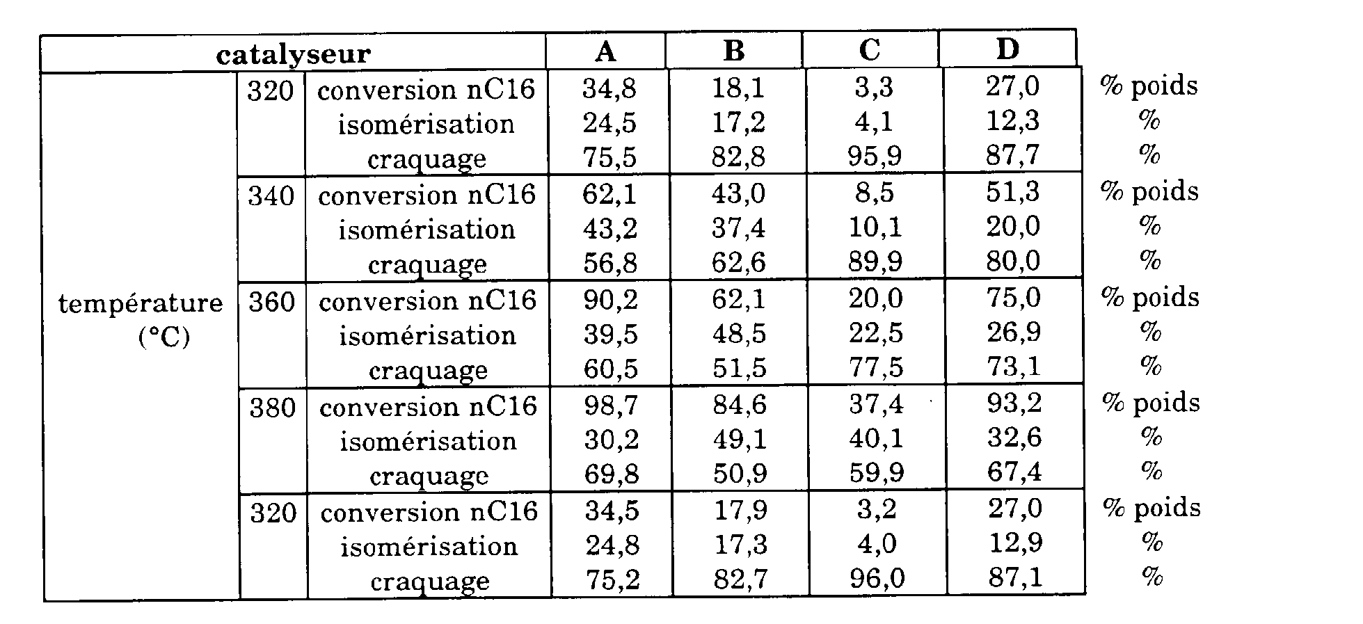
L'activité est représentée par le niveau de conversion du réactif normal hexadécane pour une température donnée. Les sélectivités pour les réactions d'isomérisation du normal hexadécane en iso hexadécane et de craquage du normal hexadécane en hydrocarbure plus légers sont calculées en divisant les rendements en produits d'isomérisation et en produits de craquage par la conversion.The activity is represented by the conversion level of the normal reagent hexadecane for a given temperature. Selectivities for isomerization reactions of normal hexadecane to iso hexadecane and cracking of normal hexadecane into lighter hydrocarbons are calculated by dividing the yields of isomerization products and cracked products by conversion.
Les résultats montrent clairement qu'il existe des écarts importants entre ces solides catalytiques. L'échantillon A se révèle être le plus actif quelque soit la température, alors que l'échantillon C est le plus sélectif. La précision relative établie dans l'exemple 1 est largement suffisante pour établir les écarts observés.The results clearly show that there are significant differences between these catalytic solids. Sample A proves to be the most active whatever the temperature, while sample C is the most selective. The relative precision established in example 1 is largely sufficient to establish the differences observed.
Appliqué à la sélection de solides catalytiques, l'appareillage et la méthode selon l'invention permet donc d'évaluer rapidement, en parallèle et avec une précision élevée plusieurs solides catalytiques.Applied to the selection of catalytic solids, the apparatus and the method according to the invention therefore makes it possible to rapidly assess, in parallel and with high precision several catalytic solids.
Claims (9)
Applications Claiming Priority (2)
| Application Number | Priority Date | Filing Date | Title |
|---|---|---|---|
| FR9908281A FR2795512B1 (en) | 1999-06-28 | 1999-06-28 | AUTOMATIC MULTI-REACTOR METHOD AND DEVICE FOR EVALUATING CATALYSTS WITH IN-LINE ANALYSIS WITHOUT LIQUID / GAS SEPARATION |
| FR9908281 | 1999-06-28 |
Publications (1)
| Publication Number | Publication Date |
|---|---|
| EP1065504A1 true EP1065504A1 (en) | 2001-01-03 |
Family
ID=9547415
Family Applications (1)
| Application Number | Title | Priority Date | Filing Date |
|---|---|---|---|
| EP00401455A Withdrawn EP1065504A1 (en) | 1999-06-28 | 2000-05-25 | Automatic multi-reactor apparatus and method for assessing catalysts with on-line analysis without liquid/gas separation |
Country Status (4)
| Country | Link |
|---|---|
| US (1) | US6548305B1 (en) |
| EP (1) | EP1065504A1 (en) |
| CA (1) | CA2312520A1 (en) |
| FR (1) | FR2795512B1 (en) |
Cited By (2)
| Publication number | Priority date | Publication date | Assignee | Title |
|---|---|---|---|---|
| WO2002092220A1 (en) * | 2001-05-11 | 2002-11-21 | Avantium International B.V. | Reactor assembly |
| FR2919058A1 (en) * | 2007-07-17 | 2009-01-23 | Inst Francais Du Petrole | METHOD AND INSTALLATION FOR TESTING CATALYSTS |
Families Citing this family (12)
| Publication number | Priority date | Publication date | Assignee | Title |
|---|---|---|---|---|
| US6901334B2 (en) * | 2001-12-17 | 2005-05-31 | Rohm And Haas Company | Methods and systems for high throughput analysis |
| US7141217B2 (en) * | 2002-12-05 | 2006-11-28 | Uop Llc | Elevated pressure apparatus and method for generating a plurality of isolated effluents |
| US20040131515A1 (en) * | 2003-01-03 | 2004-07-08 | Alexanian Ara J. | Material heat treatment system and method statement regarding federally sponsored research or development |
| US7267987B2 (en) * | 2003-01-06 | 2007-09-11 | Uop Llc | Process and assembly for simultaneously evaluating a plurality of catalysts |
| US7435598B2 (en) * | 2003-11-10 | 2008-10-14 | Exxonmobil Chemical Patents Inc. | Catalyst testing apparatus and process |
| DE102011109454A1 (en) | 2011-08-04 | 2013-02-07 | Hte Aktiengesellschaft | Process for treating product fluid streams |
| CN102539618B (en) * | 2012-01-10 | 2015-02-25 | 北京昊诚油气科技有限公司 | Multi-channel high-throughput catalyst evaluation device and evaluation method |
| HUE030188T2 (en) * | 2013-01-22 | 2017-04-28 | Covestro Deutschland Ag | Method for manufacturing aromatic amines |
| US20140335626A1 (en) * | 2013-05-10 | 2014-11-13 | Cdti | Test Bench Gas Flow Control System and Method |
| CN106770891A (en) * | 2016-12-30 | 2017-05-31 | 神华集团有限责任公司 | Catalyst test apparatus and evaluation method |
| CN107941986B (en) * | 2017-10-19 | 2020-05-29 | 浙江大学 | Device for evaluating catalytic performance of catalyst |
| US11346826B2 (en) * | 2019-09-30 | 2022-05-31 | Saudi Arabian Oil Company | System and apparatus for testing and/or evaluating an industrial catalyst |
Citations (3)
| Publication number | Priority date | Publication date | Assignee | Title |
|---|---|---|---|---|
| US4099923A (en) * | 1977-01-17 | 1978-07-11 | The Standard Oil Company | Automatic catalytic screening unit |
| JPS61292054A (en) * | 1985-06-19 | 1986-12-22 | Jgc Corp | Automatic reaction analyzing instrument |
| US5266270A (en) * | 1985-06-17 | 1993-11-30 | Institut Francais Du Petrole | On-line test and analysis process and equipment making it possible to establish a material balance of a chemical reaction |
Family Cites Families (3)
| Publication number | Priority date | Publication date | Assignee | Title |
|---|---|---|---|---|
| US3431077A (en) * | 1966-07-18 | 1969-03-04 | Joseph D Danforth | Analytical apparatus |
| US5356756A (en) * | 1992-10-26 | 1994-10-18 | The United States Of America As Represented By The Secretary Of Commerce | Application of microsubstrates for materials processing |
| US6063633A (en) * | 1996-02-28 | 2000-05-16 | The University Of Houston | Catalyst testing process and apparatus |
-
1999
- 1999-06-28 FR FR9908281A patent/FR2795512B1/en not_active Expired - Fee Related
-
2000
- 2000-05-25 EP EP00401455A patent/EP1065504A1/en not_active Withdrawn
- 2000-06-23 CA CA002312520A patent/CA2312520A1/en not_active Abandoned
- 2000-06-28 US US09/604,736 patent/US6548305B1/en not_active Expired - Lifetime
Patent Citations (3)
| Publication number | Priority date | Publication date | Assignee | Title |
|---|---|---|---|---|
| US4099923A (en) * | 1977-01-17 | 1978-07-11 | The Standard Oil Company | Automatic catalytic screening unit |
| US5266270A (en) * | 1985-06-17 | 1993-11-30 | Institut Francais Du Petrole | On-line test and analysis process and equipment making it possible to establish a material balance of a chemical reaction |
| JPS61292054A (en) * | 1985-06-19 | 1986-12-22 | Jgc Corp | Automatic reaction analyzing instrument |
Non-Patent Citations (1)
| Title |
|---|
| PATENT ABSTRACTS OF JAPAN vol. 011, no. 156 (P - 578) 21 May 1987 (1987-05-21) * |
Cited By (5)
| Publication number | Priority date | Publication date | Assignee | Title |
|---|---|---|---|---|
| WO2002092220A1 (en) * | 2001-05-11 | 2002-11-21 | Avantium International B.V. | Reactor assembly |
| US7625526B2 (en) | 2001-05-11 | 2009-12-01 | Avantium International B.V. | Reactor assembly |
| EP2263790A3 (en) * | 2001-05-11 | 2011-01-05 | Avantium International B.V. | Reactor assembly |
| FR2919058A1 (en) * | 2007-07-17 | 2009-01-23 | Inst Francais Du Petrole | METHOD AND INSTALLATION FOR TESTING CATALYSTS |
| WO2009016278A1 (en) * | 2007-07-17 | 2009-02-05 | Ifp | Catalyst testing method and unit |
Also Published As
| Publication number | Publication date |
|---|---|
| FR2795512A1 (en) | 2000-12-29 |
| US6548305B1 (en) | 2003-04-15 |
| FR2795512B1 (en) | 2001-08-03 |
| CA2312520A1 (en) | 2000-12-28 |
Similar Documents
| Publication | Publication Date | Title |
|---|---|---|
| EP1072886A1 (en) | Automatic multi-reactor apparatus and method for assessing catalysts with a heavy hydrocarbonaceous feedstock | |
| EP1065504A1 (en) | Automatic multi-reactor apparatus and method for assessing catalysts with on-line analysis without liquid/gas separation | |
| Laudenschleger et al. | Identifying the nature of the active sites in methanol synthesis over Cu/ZnO/Al2O3 catalysts | |
| US6867047B2 (en) | Method and apparatus for preventing nitrogen interference in pyro-electrochemical methods | |
| JP4688817B2 (en) | Apparatus and method for controlling the pressure and flow rate of parallel reactors | |
| EP2263790B1 (en) | Reactor assembly | |
| CN111936844A (en) | Method for analyzing process streams | |
| EP0206905B1 (en) | On line test and analysis method and apparatus to obtain a material balance of a chemical reaction | |
| EP1064992A1 (en) | Distributor for multi-reactors | |
| US7435598B2 (en) | Catalyst testing apparatus and process | |
| US4135881A (en) | Method and apparatus for determining the thermal cracking behavior of hydrocarbon feeds for cracking furnaces | |
| Liu et al. | Identification of coke precursors in heptane reforming with a multioutlet fixed-bed reactor and a novel vibrational microbalance | |
| EP1319951A2 (en) | Methods and systems for high throughput analysis | |
| Petrov | Problems and challenges about accelerated testing of the catalytic activity of catalysts | |
| EP3102321B1 (en) | Device for evaluation of at least one performance criterion of heterogeneous catalysts | |
| US7373259B2 (en) | Method and apparatus for performing chemical reactions in a plurality of samples | |
| Mills et al. | A novel reactor for high-throughput screening of gas–solid catalyzed reactions | |
| FR2529472A1 (en) | NEW TYPE OF CATALYTIC TEST MICROUNITIS WITH SAMPLE VALVE SAMPLING SYSTEM | |
| Van Staden | Analytical continuous flow systems. Where two worlds collide! From gravimetry and test tubes to flow systems to FIA to SIA to PAT and from Orsat to control room to PAT to TAP | |
| US3207585A (en) | Analysis by quantitative combustion | |
| WO2004020084A1 (en) | Combinatorial catalytic reactor | |
| Rashid | Automated lab-reactor experimenting in CO2 hydrogenation | |
| FR2922645A1 (en) | Sampling system for liquid hydrocarbon effluent in petrochemical industry, has three valves placed in series and equipped with pneumatic or electric control system, where system implements opening and closing sequences of valves | |
| Burkhardt | Determination and modeling of the influence of the fluid-dynamics in hydro-treating bench scale plants | |
| EP1146334A1 (en) | Apparatus and method for testing samples of a solid material |
Legal Events
| Date | Code | Title | Description |
|---|---|---|---|
| PUAI | Public reference made under article 153(3) epc to a published international application that has entered the european phase |
Free format text: ORIGINAL CODE: 0009012 |
|
| AK | Designated contracting states |
Kind code of ref document: A1 Designated state(s): DE IT NL |
|
| AX | Request for extension of the european patent |
Free format text: AL;LT;LV;MK;RO;SI |
|
| 17P | Request for examination filed |
Effective date: 20010703 |
|
| AKX | Designation fees paid |
Free format text: DE IT NL |
|
| GRAP | Despatch of communication of intention to grant a patent |
Free format text: ORIGINAL CODE: EPIDOSNIGR1 |
|
| STAA | Information on the status of an ep patent application or granted ep patent |
Free format text: STATUS: THE APPLICATION IS DEEMED TO BE WITHDRAWN |
|
| 18D | Application deemed to be withdrawn |
Effective date: 20040504 |