EP1062823B1 - System and device for accessing services of a mobile communication network directly or via an ip network - Google Patents
System and device for accessing services of a mobile communication network directly or via an ip network Download PDFInfo
- Publication number
- EP1062823B1 EP1062823B1 EP99910577A EP99910577A EP1062823B1 EP 1062823 B1 EP1062823 B1 EP 1062823B1 EP 99910577 A EP99910577 A EP 99910577A EP 99910577 A EP99910577 A EP 99910577A EP 1062823 B1 EP1062823 B1 EP 1062823B1
- Authority
- EP
- European Patent Office
- Prior art keywords
- mobile station
- mobile
- communication network
- network
- communication
- Prior art date
- Legal status (The legal status is an assumption and is not a legal conclusion. Google has not performed a legal analysis and makes no representation as to the accuracy of the status listed.)
- Revoked
Links
Images


Classifications
-
- H—ELECTRICITY
- H04—ELECTRIC COMMUNICATION TECHNIQUE
- H04L—TRANSMISSION OF DIGITAL INFORMATION, e.g. TELEGRAPHIC COMMUNICATION
- H04L67/00—Network arrangements or protocols for supporting network services or applications
- H04L67/01—Protocols
- H04L67/08—Protocols specially adapted for terminal emulation, e.g. Telnet
-
- H—ELECTRICITY
- H04—ELECTRIC COMMUNICATION TECHNIQUE
- H04M—TELEPHONIC COMMUNICATION
- H04M1/00—Substation equipment, e.g. for use by subscribers
- H04M1/72—Mobile telephones; Cordless telephones, i.e. devices for establishing wireless links to base stations without route selection
- H04M1/725—Cordless telephones
-
- H—ELECTRICITY
- H04—ELECTRIC COMMUNICATION TECHNIQUE
- H04Q—SELECTING
- H04Q3/00—Selecting arrangements
- H04Q3/58—Arrangements providing connection between main exchange and sub-exchange or satellite
- H04Q3/62—Arrangements providing connection between main exchange and sub-exchange or satellite for connecting to private branch exchanges
-
- H—ELECTRICITY
- H04—ELECTRIC COMMUNICATION TECHNIQUE
- H04Q—SELECTING
- H04Q3/00—Selecting arrangements
- H04Q3/64—Distributing or queueing
- H04Q3/66—Traffic distributors
-
- H—ELECTRICITY
- H04—ELECTRIC COMMUNICATION TECHNIQUE
- H04M—TELEPHONIC COMMUNICATION
- H04M1/00—Substation equipment, e.g. for use by subscribers
- H04M1/253—Telephone sets using digital voice transmission
- H04M1/2535—Telephone sets using digital voice transmission adapted for voice communication over an Internet Protocol [IP] network
-
- H—ELECTRICITY
- H04—ELECTRIC COMMUNICATION TECHNIQUE
- H04M—TELEPHONIC COMMUNICATION
- H04M1/00—Substation equipment, e.g. for use by subscribers
- H04M1/60—Substation equipment, e.g. for use by subscribers including speech amplifiers
- H04M1/6033—Substation equipment, e.g. for use by subscribers including speech amplifiers for providing handsfree use or a loudspeaker mode in telephone sets
- H04M1/6041—Portable telephones adapted for handsfree use
-
- H—ELECTRICITY
- H04—ELECTRIC COMMUNICATION TECHNIQUE
- H04M—TELEPHONIC COMMUNICATION
- H04M2250/00—Details of telephonic subscriber devices
- H04M2250/02—Details of telephonic subscriber devices including a Bluetooth interface
-
- H—ELECTRICITY
- H04—ELECTRIC COMMUNICATION TECHNIQUE
- H04W—WIRELESS COMMUNICATION NETWORKS
- H04W4/00—Services specially adapted for wireless communication networks; Facilities therefor
- H04W4/16—Communication-related supplementary services, e.g. call-transfer or call-hold
-
- H—ELECTRICITY
- H04—ELECTRIC COMMUNICATION TECHNIQUE
- H04W—WIRELESS COMMUNICATION NETWORKS
- H04W88/00—Devices specially adapted for wireless communication networks, e.g. terminals, base stations or access point devices
- H04W88/02—Terminal devices
- H04W88/06—Terminal devices adapted for operation in multiple networks or having at least two operational modes, e.g. multi-mode terminals
-
- H—ELECTRICITY
- H04—ELECTRIC COMMUNICATION TECHNIQUE
- H04W—WIRELESS COMMUNICATION NETWORKS
- H04W92/00—Interfaces specially adapted for wireless communication networks
- H04W92/02—Inter-networking arrangements
Definitions
- the present invention relates to mobile communication systems and particularly to a system for transferring information between a mobile station and a mobile communication network.
- a conventional realisation of an above mentioned type of office communication system comprises a company telephone exchange for providing telephone services and telephones connected to it over twisted-pair connections and a separate local area network (LAN) in which applications for advanced telecommunication services have been implemented and which has the intelligence to run them.
- the local network is connected to the telephone exchange using a telecommunication server (Telephony Server) which supports the traditional subscriber server architecture in which subscribers are subscribers' computers connected to the local network. For example call-, data-, facsimile-, electronic mail- and speech mail services are connected within an office utilising the telecommunication server.
- users can also e.g. control telephone services using their computer terminals connected to the local network.
- the whole integrated office communication system is connected to public telephone network through the telephone exchange.
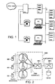
- FIG 1 presents an example of a prior known office communication system in which users' telephones TP (TelePhone) have been connected by wire connections and a local area network (LAN) has been connected over a telecommunication server TS (Tele Server) into a telephone exchange PBX (Private Branch Exchange) which is connected to a public telephone network PSTN/ISDN (PSTN, Public Switched Telephone Network, ISDN, Integrated Services Digital Network).
- TP TransmissionPhone
- PBX Private Branch Exchange
- PSTN/ISDN PSTN, Public Switched Telephone Network, ISDN, Integrated Services Digital Network
- LAN local area network
- servers executing various services such as data base server DBS (Data Base Server), voice server VS (Voice Server) and electrical mail server EMS (Electrical Mail Server) and on the other hand the users' computers PC (Personal Computer).
- DBS Data Base Server
- voice server VS Voice Server
- EMS Electrical mail server
- the network of small base stations would be already a third overlapping telecommunication network within the same office, and accordingly it is clear that in a preferable solution, which the present invention is aiming at, also the arrangement supporting radio communication stations should be realised using essentially the same means and telecommunication networks than the rest of the transfer of information in the office.
- EP 766490 discloses an integrated data transfer system including a cellular network (GSM) and a wireless LAN (Hiperlan).
- GSM cellular network
- Hiperlan wireless LAN
- the connection between the networks is controlled by a gateway computer located in each wireless LAN.
- the gateway computer operates like a base station controller (BSC).
- BSC base station controller
- the gateway computer carries out protocol conversions between the cellular network protocol and the LAN protocol.
- GSM Global System for Mobile Communications
- the invention can be used in connection with any functionally equivalent mobile communication network, such as the NMT (Nordic Mobile Telephone), the AMPS (Advanced Mobile Phone Service), the DECT (Digital European Cordless Telecommunications), the DCS1800 (Digital Cellular System for 1800 MHz), etc. Neither is the selection of the access network essential as regards the present invention.
- the solution can correspondingly be applied in connection with other fixed and wireless access techniques, such as the WLAN (Wireless Local Area Network), the Ethernet, the ATM (Asyncronous Transfer Mode), the WATM (Wireless Asyncronous Transfer Mode), the HIPERLAN, the LPRF (Low Power RF), etc.
- WLAN Wireless Local Area Network
- Ethernet Ethernet
- ATM Advanced Transfer Mode
- WATM Wired Asyncronous Transfer Mode
- HIPERLAN the LPRF (Low Power RF)
- LPRF Low Power RF
- Figures 2 to 8 illustrate a first embodiment in which a virtual mobile station is established in operator's equipment
- Figure 9 onwards illustrate a second embodiment in which the virtual mobile station is in the user's equipment.
- the block diagram in Figure 2 illustrates the basic elements of the GSM system.
- Mobile stations MS are in connection with base stations BTS using radio communication.
- the base stations BTS are further, through a so-called Abis interface, connected to a base station controller BSC, which controls and manages several base stations.
- the entity formed by several base stations BST and a single base station controller BSC controlling them are called a base station system BSS.
- the base station controller BSC manages radiocommunication channels, as well as handovers.
- the base station controller BSC is, through the so-called A interface, in connection with a mobile services switching centre (MSC), which co-ordinates the establishment of connections to and from mobile stations.
- MSC mobile services switching centre
- a connection can further be established to a subscriber not operating under the mobile communication network.
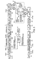
- the block diagram in Figure 3 illustrates in more detail the transmission and reception functions of a mobile station in accordance with the GSM system.
- the first phase of a transmission sequence is analogue speech digitation 201 and coding 202.
- a sample is taken by an A/D converter 201 at a frequency of 8 kHz and a speech-coding algorithm assumes that the incoming signal is of 13-bit linear PCM.
- the samples provided by the A/D converter are segmented to 160-sample speech frames, whereupon the duration of each speech frame is 20 ms.
- the speech coder 202 processes the 20-ms speech frames, in other words, 20 ms of speech is taken into a buffer before the coding begins.
- the coding operations are carried out frame-specifically or as their sub-frames (as blocks of 40 samples). As a result of the coding of the speech coder 202, one frame produces 260 bits.
- the signalling and logical messages come directly from a control unit 219, that controls the mobile station's blocks, to the block coding block 203a and, naturally, no speech coding is carried out for these data message.
- the signalling and logical messages received at the reception are taken from a channel-decoding block 215 to the control unit 219.
- block coding 203a a bit sequence is connected to the end of the frame by means of which transport errors can be detected at the reception.
- convolution coding 203b the redundancy of the speech frame is increased. Thus, a total of 456 bits are transmitted per one 20-ms frame.
- These 456 bits are interleaved 204 and the interleaving 204 also has two phases.
- the purpose of interleaving is to spread the transfer errors, which normally occur as error bursts, evenly over the entire transmitted data, whereupon channel decoding is more effective. After de-interleaving, the error burst turns into separate error bits, which can be corrected in channel decoding.
- the next phase in the transmission sequence is data encryption 205. Encryption 205 is implemented by means of an algorithm, which is one of the most closely guarded secrets of the GSM. By means of encryption, unauthorised listening of calls which is possible in analogue networks, is prevented.
- the burst to be transmitted is formed 206 by adding thereto a training period, tail bits and a protection period.
- the burst to be transmitted is taken to a GMSK modulator 207, which modulates the burst for transmission.
- the GMSK modulation method (Gaussian Minimum Shift Keying) is a digital, standard-amplitude modulation method, wherein information is included in the changes of a phase.
- a transmitter 226 mixes the modulated burst through one or more intermediate sequences for 900 megahertz and transmits it through an antenna to a radio interface.
- the transmitter 226 is one of three radio frequency blocks 30.
- a receiver 228 is the first bock on the reception side reversing the operations of the transmitter 226.
- the third RF block is a synthesiser 227, which takes care of the formation of frequencies.
- the GSM system has frequency hopping in use, wherein the transmission and reception frequencies change in every TDMA frame. Frequency hopping improves the quality of the connection, but set strict requirements on the synthesiser 227.
- the synthesiser 227 must be able to switch from one frequency to another very rapidly; in less than a millisecond.
- a linear detection is made 212, eg, by a channel equaliser of the received samples the aim being to find out the transmitted bit sequence.
- decryption 213 and de-interleaving 214 are carried out, channel decoding 215 is implemented for the detected bits and the error sum is checked by cyclic redundancy check (CRC).
- CRC cyclic redundancy check
- the aim is to correct the bit errors due to the transfer of the burst.
- the 260-bit long speech frame, subsequent to channel decoding 215, contains the transmitted parameters describing speech by means of which a speech decoder 216 forms digital samples of the speech signal. The samples are D/A converted 217 for a speaker 32 for reproduction.
- the main unit controlling the mobile station is the control unit 219, which essentially controls the blocks described above, co-ordinates their functions and controls the timing.
- the block diagram in Figure 4 illustrates an arrangement, according to an embodiment of the present invention, for using the services of a mobile communication network through an IP access protocol.
- An interworking unit 40 (IWU) has been connected to a mobile communication system's mobile services switching centre 31, whose interface towards the mobile services switching centre corresponds to a normal interface of a base station controller BSC, ie, the A interface and, towards the IP network, it corresponds to a normal interface between the IP network and an IP terminal.
- the IWU is a new network element according to the present invention, which comprises necessary means for interlinking the functionalities of the mobile communication system and the IP network.
- the element AP presents the IP network's connection point.
- the interworking unit 40 comprises a first functional block 41, which comprises means for emulating the base station controller of the mobile communication system towards the mobile services switching centre.
- the IWU also comprises a second functional block 42, which comprises means for functioning as an IP host towards the Internet or a corresponding telecommunications network, such as the ISDN, AMT, etc.
- a mobile station comprises means for switching to an access network; the mobile station, presented in Figure 4, is coupled to the LAN 32, for example, by connecting the mobile station to a personal computer coupled to a subscriber's LAN using a cable, an infrared connection or a radio transmitterreceiver pair.
- the manner in which the mobile station is coupled to the network point is not essential as regards the invention. Later, it is possible that mobile stations will be equipped with sufficient IP functionality, whereupon no separate terminal is required.
- the mobile station switches to a fixed access point of a local area network.
- the access point can also be some other access point, for example, that of a wireless local area network, as we will later demonstrate.
- the mobile station can make a decision on switching to the access network after noticing, for example, that it is in the subscription area of a wireless access network.
- the mobile station When the mobile station is connected to the network through a terminal, the mobile station will detect the switching or unswitching, for example, from an indicator 37B of an indication signal of the selected core of a multicore cable or of an information access service (IAS) statutory for equipment in accordance with the IrDA standard.
- IAS information access service
- the mobile station In connection with switching to the local area network, the mobile station transfers the dynamic data relating to the state of the mobile station and the calls in progress to the interworking unit through the IP network. After this, the mobile station's traditional radio frequency parts switch off and the mobile station changes over to communicate with the interworking unit 40 through the IP network.
- said arrangement means that, for example, blocks 233, 201, 202, 216, 217, 219 and 232 are maintained and the rest of the blocks are switched off, whereupon the mobile station transmits and receives speech coded in accordance with the 13Kbps GSM specification.
- a mobile station 34 When operating in the GSM system, a mobile station 34 signals with a mobile services switching centre 31 over a base station controller.
- the interworking unit 40 is not an element that only carries out protocol conversions; it also contains a functional unit 43 for maintaining virtual terminals.
- the mobile station 34 When changing over to the IP mode, the mobile station 34 transfers the dynamic data relating to the state of the mobile station and the calls in progress to a virtual terminal vMS 35 to be established in the interworking unit 40. These data are maintained in a state machine, which is located in the virtual terminal.
- the state machine means a functional entity that describes the allowed changes in the state relating to the functioning of the mobile station and the related messages according to the protocol. The functionality part described by the state machine maintains the data on the possible changes in the state relating to said protocol layer, the instantaneous state, the data structures relating to the change in the state, etc.
- a state machine in connection with the GSM means the mobile station's functionality part, which controls the functionalities relating to the mobile station's GSM Layer 3 protocol (NULL, current switched on, switched to a base station, etc.)
- this state machine of the upper most level maintains a partial state machine for the mobile station's every connection, whereupon the state of the connection can be, for example, NULL, call initiated, call proceeding, active, etc.
- the simplified block diagram presented in Figure 6 illustrates an implementation of the mobile station's functionality and the division of its hierarchy in connection with the establishment of a virtual terminal.
- the interworking unit 40 has been connected to the mobile services switching centre 31 through a fixed network of the GSM system, whereupon the bottom layer of the protocol stack of the mobile services switching centre 31 and the interworking unit 40 is a transport protocol 315, 411 of a fixed network 50 of the GSM system.
- the block 41 of the interworking unit comprises layers 412 required for emulating a network sub-system.
- a block 42 of the interworking unit comprises protocols MAC 421, IP 422 and UDP 423 relating to IP communication.
- Corresponding protocols 341, 342, 343 are found in the protocol stack of the mobile station 34 that operates in the network mode.
- the protocol stack of the virtual terminal 43 comprises the GSM functionality entity described by a state machine 431, which comprises at least a radio resource (RR), mobility management (MM) and call management (CM).
- RR radio resource
- MM mobility management
- CM call management
- RR radio resource
- MM mobility management
- CM call management
- a protocol 432 GSM over IP
- a corresponding protocol 344 is found in the mobile station operating in the network mode, which also comprises the necessary applications for processing the basic services (speech, short message, telecopy) of a mobile communication system.
- maintaining the state machine in the virtual terminal 35 is an application-specific solution, because the virtual terminal must maintain data on the state of the connection in the direction of both the mobile communication system and the mobile station 34.
- the signalling of the virtual terminal can be controlled in the direction of both the mobile communication network and the mobile station. It should be noted that due to the state machine maintained by the virtual terminal, the signalling to be implemented in different directions is independent of the protocol, in other words, the changing of the protocol in either direction does not interrupt the functioning of the virtual terminal.
- the interworking unit requires the data stored in a subscriber identity module: the SIM card.
- the SIM card is an intelligent card, wherein the identification information on both the subscriber and the terminal, as well as an information field containing various types of data defined by the GSM standard and provided by the subscriber, have been stored.
- the SIM card we refer to the pages 67-71, 444-492 and 561 of the above-mentioned Mouly-Pautet's GSM guide.
- the most important part of the data contained in the SIM card can be kept as static information, whereupon corresponding information can be kept stored in the memory of the interworking unit.
- the IWU 40 starts the virtual terminal 35, which emulates the functioning of the actual mobile station 34 towards the mobile communication system. It receives signals of the mobile communication system through the first functional block 41of the interworking unit and, on the basis of the status data it maintains, it carries out signalling towards the mobile communication system. It receives, through the second functional block 42 of the interworking unit, the data in accordance with the IP transmitted by the actual terminal, compares the message to the status data it maintains and, on the basis of it, generates a signal required at the time in question for being transmitted by the mobile communication system.
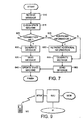
- the flow diagram presented Figure 7 illustrates the functioning of a virtual terminal on the basis of a message arrived from a mobile communication system.
- the virtual terminal 35 receives a message through the first functional block 41 of the interworking unit.
- the virtual terminal compares the checked message to the state machine it maintains and, on the basis of it, defines the message required for changing over to the next state.
- the virtual terminal defines whether a connection to the mobile station 34 that operates in the network mode is required for generating the next signal or whether the required data are included in the subscriber information stored in the interworking unit.
- the virtual terminal If a connection to the mobile station is necessary, the virtual terminal generates the message relating to said function (point 630) and sends it through the IP network to the mobile station 34 (point 635). At the same time, it updates the state of the process in question to the signalling state maintained by it (point 640). If no connection the mobile station 34 is required and the virtual terminal concludes that the necessary signal can be managed by itself, the virtual terminal checks whether the subscriber information stored in the interworking unit is required for the reply or whether the reply message can directly be generated on the basis of the status data (point 625). If additional information is required, the virtual terminal retrieves it from the interworking unit's database (point 650) and, on the basis of it, generates a message to be transmitted to the mobile communication system (point 655).
- the virtual terminal If no additional information is required, the virtual terminal generates a message in accordance with the mobile communication system's protocol defined on the basis of the status data (point 655). In point 660, the message generated by the virtual terminal is transmitted to the mobile services switching centre through the first functional block 41 of the interworking unit. At the same time, the virtual terminal updates the state of the process in question in the state machine it maintains (point 640).
- One way of managing a connection between the interworking unit and the mobile station is to convert the GSM signalling into packets in accordance with the IP and to transfer the signalling to the mobile station in the GSM format.
- signalling between the mobile station and the mobile services switching centre includes a lot of signalling relating to the use of a radio resource the transfer of which in the arrangement according to the invention is unnecessary.
- a connection over an IP link should preferably be managed by simplifying said protocol during network operation.
- This kind of protocol can be established, for example, by selecting a group of AT commands, which are transported over a UDP/TCP protocol layer or by using methods in accordance with the H.323 protocol family standardised by the ITU-T.
- a simple, manufacturer-specific protocol can also be defined.
- the implementation of said protocol can be illustrated by giving an example of the functions, which are separated from one another between a mobile station that operates in the network mode and an interworking unit. These include, for example, the functions 1.1. - 1.7. listed in the first column of Table 1. The second column of Table 1 contains a functional description of messages, which are separated from one another by means of a protocol according to the invention.
- a mobile station When a subscriber wants to make a call through a mobile communication network (1.1), a mobile station makes a request for a call and receives the message of the making of the call given by an interworking unit, before the transfer of the data relating to the call begins.
- the subscriber receives a call (1.2)
- the mobile station receives the message of the incoming call from the interworking unit and informs the interworking unit of the reception of the call before the transfer of the data relating to the call begins.
- the mobile station When either the subscriber or the other party wants to cut off the call (1.3), the mobile station gives or receives a request to cut off the call.
- both the mobile station and the interworking unit should be able to distinguish whether it is a question of the transfer of speech (1.4), a short message (1.5) or telecopied data (1.6).
- the message 1.7 contains the status data on the calls in progress, which are transported when the virtual terminal is taken into use or when the use of the virtual terminal is terminated as described above.
- the above-mentioned command group is one possible way of implementation. For example, making a call can be arranged so that the mobile station identifies, on the basis of the first speech packets, that it is a question of call in which case not even a separate call phase is required.
- the virtual mobile station unit can be automatically adapted to cut off the call when the reception of the call packet from the mobile station stops.
- the Mobile IP is a protocol, which is currently being standardised. For its more detailed description, we refer to the Intemet Engineering Task Force (IETF) instructions Request For Comments (RFC) 2002.
- the Mobile IP describes the home agent (HA) of a network element to be connected to the home network of a mobile subscriber. When the subscriber moves away from the home network, the HA maintains the data on the subscriber's address and routes the data packets, assigned to the mobile subscriber, to the address at which the subscriber is registered at that particular moment. Thanks to this, the data packets are routed to the subscriber's new address without a significant number of them being lost due to the transfer.
- IETF Intemet Engineering Task Force
- RRC Request For Comments
- connection between the mobile station that operates in the IP mode and the interworking unit can be maintained due to the Mobile IP, whereupon a virtual mobile station that operates within the interworking unit seems to remain in the same cell as for the mobile communication network, when it operates through the same home network's home agent.
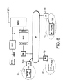
- the block diagram in Figure 8 illustrates an arrangement according to the invention presented above.
- the mobile communication system containing an interworking unit has been connected, through the interworking unit, to an IP network.
- Different access networks 71, 72 and 73 reached through routers 710, 711, 721, 731 of the IP network, provide the mobile communication system's mobile station with IP access points 712, 722, 732.
- the IP network is formed of a large number of MAC-level access networks many of which support the subscriber's mobility in the access network in question (eg, 802.11 and WATM).
- the Mobile IP enables mobility between the IP access protocols, for example, between two separate WLANs or between an Ethernet and a WLAN.
- a mobile communication system for example GSM, enables mobility over the Mobile IP between mobile communication networks.
- GSM Global System for Mobile communications
- an arrangement according the present invention produces an extended functionality that supports mobility between a mobile communication network and an IP network, and the subscriber is provided with an opportunity to preferably maintain a flexible and uninterrupted connection within an extremely wide service area.
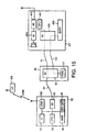
- FIG. 9 illustrates an architecture for a system according to an embodiment of the invention.
- the system comprises a mobile station MS, a mobile communication network MOB e.g. Public Land Mobile Network (PLMN), and a communication network IP, all connected by virtue of an inter-working unit IWU.
- Interfacing the IWU and the MS is a base transceiver emulator BTSE.
- the mobile station MS is a generic terminal product portfolio consisting of full-featured cellular phone that supports services of mobile communication network. When no access to the communication network IP is available, the MS transfers information (such as speech and data) through the MOB in a normal way as explained with Fig 2.
- FIG 10 is a block diagram illustrating the modules of a mobile station MS.
- a Central Processing Unit 401 controls the blocks responsible for the mobile station's different functions: a Memory (MEM) 402, a Radio Frequency block (RF) 403, a User Interface (Ul) 404 and an Interface Unit (IU) 405.
- the microprocessor's operating instructions, i.e. program and the mobile station's basic menus have been stored in the mobile station in advance, e.g. during the manufacturing process, in the memory 402.
- the microprocessor uses the RF block 403 for transmitting and receiving messages on the radio path and communicates with the user by the UI 404.
- the Interface Unit 405 is the link to a data processing entity, and it is controlled by the CPU 401.
- the data processing entity may be an integrated data processor or external data processing equipment.
- FIG 11 illustrates the functionalities of a mobile station MS according to the invention, represented with layers 1 to 3 of the 7 OSI reference model.
- LayErs are data communication protocols whose purpose is to provide a link between 2 communicating devices, and are known to a person skilled in the art.
- the illustrated layers are physical layer (layer 1) 51, data link layer (layer 2) 52 and network layer (layer 3) 53.
- Network layer 53 of the mobile station MS provides call control management 531 (including supplementary services 532 and short message services 533). This layer also provides mobile management 534 and radio resource management 535.
- MUX 536 which "switches" to a second branch of layer 2 to demand services of the data link (FBUS Ctrl 523) and physical layer (FBUS 522) when the mobile station MS is connected to the communication network through IWU.
- the network demands the services of the data link layer 52 (data link 521 and control 522) and the physical layer 51 of the first branch, to allow the mobile station MS to perform and report its measurements about the surrounding GSM network (neighbouring BTSs) and thus comply with GSM requirements.
- the MS With e.g. a serial cable, any RF interface or infrared link and with an appropriate software to a PC, the MS enables through the second branch connection to mobile communications network and other telephony entities within the communication network IP.
- the communication system IP may be one of several kinds, such as a data communication network, internet, intranet, LAN, WAN, ATM packet network.
- IWU acts as a gateway between system entities.
- An embodiment of the IWU is shown in Figure 12 which illustrates the Wireless Intemet Office (WIO) concept.
- WIO allows a MS 63 subscriber to utilise communication networks 62, such as private intranets to carry services of cellular network 61 when within coverage area.
- the IWU comprises several network elements, including an intranet mobile cluster GSM/IP Gateway 601, an intranet location register (ILR) 602, a WIO gatekeeper 63 and a WIO A-gateway 604.
- ILR intranet location register
- Information such as data and/or speech may be transferred from the mobile station 63 to the IP local area network 62 by two routes, each of which includes a BTS emulator BTSE.
- the mobile station 63 In a first mode, the mobile station 63 is connected to the local area network 62 via a personal base unit 64 (PBU), which itself comprises a BTS emulator BTSE.
- PBU personal base unit 64
- the mobile station 63 forms part of a mobile cluster.
- the information is transmitted to the local area network via a GSM BTS 65 dedicated to that cluster, and an IMC GSM/IP Gateway 601.
- the BTS transmits the signal over the A bis interface, and the IMC Gateway 601 performs a protocol transform from GSM to H.323, so that the signal can be transmitted over the IP local area network.
- the wireless intranet office architecture uses the H.323 protocol for the signalling and data connections inside the inter-working unit).
- the basic access interfaces to the cellular network are the air interface, the A-interface, the MAP protocol, the ISUP/TUP interface and the DSS.1 interface.
- the A-interface is an interface to mobile switching centre and the MAP interface is an interface to HLR/VLR.
- ISUP/TUP interface connects switching centres, while the DSS.1 interface resides in between of the BSX and switching center.
- the air interface connecting mobile terminals to the network can be any RF interface or infrared link.
- Candidate RF interfaces include e.g. Low Power RF (LPRF), 802.11, wireless LAN (WLAN) WATM and HIPERLAN.
- the air interface can also be replaced with a physical connection (e.g. RS-232 serial cable or Universal Serial Bus (USB).
- the GSM network sees this new access network as a BSS entity. New network entities are added to the access network to modify/de-modify cellular signalling.
- System design principle is to fulfil ITU-T's recommendation H.323 and enhances it with mobility extensions.
- the WIO A-gateway 604 looks like a base station controller to the MSC 611.
- a local area network 71 is provided with an internet mobile cluster IMC 72, an LPRF cell 74 and a landline connection 75.
- the IMC comprises a plurality of mobile stations, a BTS (private GSM BTS) and a server in the form of an IMC GSM/IP gateway.
- the BTS interface between the BTS and IMC GSM/IP gateway is a GSM A-bis interface.
- the IMC GSM/IP gateway is responsible for signalling conversions between the GSM and H.323 protocols.
- the low power RF cell 74 comprises a personal base unit which has a virtual BTS and a low power transceiver, and associated mobile stations with corresponding low power RF transceivers.
- the PBU is directly connected to the WIO network.
- the PBU provides conversions between the GSM and H.323 protocols. These conversions can be seen as a bridge between cellular phone and H.323 features, which support WIO location management and mobility features.
- the landline connection comprises a landline terminal 751 hardwired to a personal base unit 752, which in tum is hardwired to the local area network.
- a WIO gatekeeper 76 which is responsible for the connection of mobile stations to within and outside the network. For example it might route a call from the server to an external system such as PSTN or it could provide connection to the IP network 87.
- the local area network is further provided with an A-intranet gateway 791 and an intranet location register 792.
- the main function of the Intranet Location Register is to store mobility management information and call statistics of the subscribers configured into the Wireless Intranet Office system. Roaming of visitors are controlled by the mobile switching centre. For visitors only temporary information will be stored into the Intranet Location Register.
- the ILR has a MAP interface to cellular system network home location network (not shown here).
- the A-Intranet Gateway 791 in this embodiment makes protocol conversion to and from IP protocol at the A-interface, and makes the cellular and Intranet location area associations. It has an operation and management software entity which operates as an administrative server gateway for corresponding agents in intranet Mobile Clusters.
- the A-Intranet Gateway operates as a firewall between public telecommunication network and private Intranet solutions.
- Intranet Mobile Cluster is simulating BSC in a local environment. It consists of minimum set of BTS functionality with reduced physical construction. Intranet Mobile Cluster is a BTS and a BTS driver software package for Windows NT including rate adaptation, an O&M agent software package and a GSM/IP Telephony Gateway entity. Intranet Mobile Cluster provides inter-working with data services and facsimile as a direct access to IP network, and it may provide local call routing capability within its radio coverage.
- the purpose of the GSM/IP Telephony Gateway is to reflect the characteristics of an Internet telephony endpoint to an Intranet Mobile Station, and the reverse, in a transparent fashion.
- the GSM/IP Telephony Gateway provides appropriate format translation of signalling and speech, i.e., audio format translations between GSM 06.10, 06.20, 06.60, J-STD-007 and G.711, G.723 and transformation of communications procedures.
- the Gateway performs call setup and clearing on both the Intemet telephony side and the Wireless Intranet Office side.
- the MS-IP (WIO) Gatekeeper 76,603 provides mobility and call management services, and certain radio resource management functions.
- the MS-IP Gatekeeper provides the following services:
- the MS-IP Gatekeeper authenticates all the network entities, i.e., Intranet Mobile Stations, Intranet Mobile Clusters, A-Intranet Gateways, IP Telephony Gateways, Intranet Location Registers, H.323 terminals, which have access to the system.
- Intranet Mobile Station authentication and registration is based on automatic Gatekeeper discovery procedure. In other cases, it's based on manual Gatekeeper registration procedure.
- Connection ciphering Part of the Gatekeeper's authentication procedure is connecition ciphering service. It provides key distribution, identification and encryption/decryption services to the Gatekeeper and other entities in the system. Service has an option to select ciphering, hashing, key distribution and signature algorithms independently. Key distribution is based on public key cryptography and message ciphering is based on secret key cryptography.
- the MS-IP Gatekeeper performs E.164 to transport address association and translation. This is done using directory service in the Intranet Locatioin Register which is updated during mobility management procedures, i.e., during TMSI reallocation, authentication, identification, IMSI detach, abort, and location updating.
- the MS-IP Gatekeeper can be configured to route call control signalling to the cellular system network or to the local call management entity within the Gatekeeper.
- the MS-IP Gatekeeper maintains also list of ongoing calls and collects call statistics. This information is stored into the Intranet Location Register by the Gatekeeper, and can be used e.g. for billing purposes.
- the MS-IP Gatekeeper must be able to handle signalling and resource management procedures (BSSMAP resources) specified in GSM recommendation 08.08.
- the MS-IP Gatekeeper uses status inquiry to poll the entity at a certain interval.
- the MS-IP Gatekeeper entity of this embodiment can be a software package for an operating system fulfilling e.g. ITUT's H.323 Gatekeeper specifications, extended with certain mobility management capabilities according to GSM 04.08.
- a preferred embodiment for a Personal Base Unit (PBU) 74 is a PC Card type of radio card for a desktop PC with a piece of software enabling wireless access to IP network. It provides LPRF cordless and wireless LAN - on 2.4 GHz band - dual-mode access exploiting an unlicensed radio spectrum. In cordless, "unlicensed" mode lower layers will be replaced with new ones, but signalling above them remains the cellular one. It also enables intelligent roaming of terminals between different radio frequency bands, i.e. between cellular and unlicensed bands as will be explained later.
- the BTSE is the element in the interface between the MS and the IWU.
- the BTSE is a PBU.
- the PBU and the MS are connected by a radio frequency (preferably LPRF) or infrared connection. Also, they may be indirectly connected, for example via a connection device such as a mobile station cradle, desk-stand or charger.
- FIG 14 illustrates the architecture of a personal base unit according to an embodiment of the present invention.
- PBU comprises a phone driver implementing the physical and data link layers 81 and 82 (FBUS 811 and FBUS Ctrl 821).
- the network layer 83 of the PBU comprises a PBU control/IMC core control 832 and an H.323 protocol entity 833 which provide protocol conversion between GSM and H.323. The conversions are needed for GSM layer 3 signalling messages while the speech is carried as GSM coded in the whole in this intranet office network.
- the PBU further comprises TCP/IP entity 821 and a local area network adapter driver for the 823 for interfacing with the local area network.
- the PBU control 832 comprises a virtual BTS 834 i.e. a base station emulator BTSE for communicating with the network layer 53 (ref: Fig.5) of a mobile station MS.
- the mobile station MS When the mobile station MS is outside the wireless intranet office environment, it operates as a normal GSM phone.
- the MUX 536 does not couple the radio resource management entity 533 with the second branch 523, 512. Voice and signalling is transmitted via the data link layer 52 and physical layer 51 over the first (GSM) branch to the cellular air interface.
- GSM first
- the mobile station MS if the mobile station MS is within the wireless intranet office, but forms part of an intranet mobile cluster, this same path is taken to the cellular air interface and the information and signalling is transmitted to the GSM BTS of that cluster.
- a PBU for example by an RF 232 serial cable or RF interface
- information such as voice, data, fax, SMS etc., is transmitted over the local area network.
- FIG 15 shows a way of connecting mobile station MS according to the invention to a terminal equipment TE incorporating the PBU.
- the connection is carried out by means of a connection device 100.
- the connection device 90 in this example can be a cradle such as a desktop stand or desktop charger.
- the connection device is described by means of a charger called intelligent charger 90.
- the intelligent charger 90 is connected releasably to terminal device TE with physical conducting wire 91 and interface unit 92. Using same interface unit 92 and conducting wire 93 the intelligent charger 90 is also connected releaseably to mobile station MS when mobile station MS has been installed to intelligent charger 90.
- Conducting wires 91 and 93 form a bus for communication between terminal device TE and mobile station MS via intelligent charger 90.
- the connections illustrated by conducting wires 91 and 93 may as well implemented in other ways, e.g. by infrared connection or by electrical connectors or the connection device 90 may be integrated into the terminal device TE.
- Terminal device TE may be e.g. a PC prior known from office environment or a workstation, which comprises among other things processor 95, memory 96 and network interface unit 97 (NI, Network Interface) for connecting terminal device TE to local area network (LAN).
- NI Network Interface
- the processor 95 handles the control in the terminal device TE for establishing a connection to the mobile station MS and after an established connection.
- Such control operations can be implemented as application software 98, which is executed by the processor.
- Interface 92 of intelligent charger 90 also includes means for arranging the charging voltage from power supply PWR to battery 413 of mobile station MS via conducting wire 100. If the connection device 90 has no own power source, it can get and transfer power to the mobile station from the terminal device TE.
- MS When mobile station MS is connected to a terminal device TE in a way characteristic of the invention, e.g. using interconnecting cable or infrared, or any RF connection, MS operates in a different mode. Switching between the two modes is detected by both terminal device TE and mobile station MS and, depending on the switching method used, switching can be detected in a number of methods. When e.g. multi-core interconnecting cable is used, one of the cores can be allocated for the indication signal. If e.g. in terminal device TE said indication signal is connected to operating voltage (e.g. + 5 V), mobile station MS detects the switching in of mobile station MS by monitoring the voltage level of the indication signal e.g. using a level detector.
- operating voltage e.g. + 5 V
- Level detector transfers the information to processor 401 controlling the system, controlled by which mobile station MS and terminal device TE go over to using wired information transfer connection.
- terminal device TE can detect connecting to mobile station MS by monitoring an indication signal of same type, the signal level of which a program installed in terminal device TE polls in interface unit 99 at certain, predetermined intervals. Because said computer program executed in processor 95 and memory 96 can be run in the background, it does not have an essential effect in the other operation of terminal device TE.
- the processor of terminal device TE detects the disconnection from interface unit 99 and processor 401 of mobile station MS from interface units 411 using the detector.
- the connection can also be switched off manually from the user interface of terminal device TE or from the user interface of mobile station MS.
- connection between mobile station MS and terminal device TE is realized using an wireless connection
- IAS-service means a handshake operation between a device (in this application mobile station MS) and a server (in this application terminal device TE) in which a device can ask a server about services available.
- LSAP ID Link Service Access Point
- infrared connection When infrared connection is used, disconnection of connection is detected using infrared transceivers. If the connecltion is established using low-power transceiver units operating on radio frequency, the establishing and disconnection of a connection takes place according to same type of principle.
- the processor 95 (executing the application software 98) of terminal device TE is monitoring the establishment of the connection.
- the processor 95 checks periodically whether mobile station MS has been installed to intelligent charger 90 or not.
- the detecting of the establishment of the connection can be carried out by mobile station MS. In both alternatives this can easily be done e.g. by monitoring the voltage of a pin of a connector as was described above in relation to the embodiment without a separate connection device 90.
- mobile station MS sends an information message to terminal device TE, in which it informs about the connection to intelligent charger 90.
- the terminal device TE may acknowledge receipt of this message.
- the MUX 536 demands the service of the second (LAN) branch layers 1 and 2, and layer 3 of the mobile station MS is seen to communicate with the BTS emulator BTSE 834 of the PBU. That is, the information (eg. speech) and GSM layer 3 signalling messages are redirected to the second branch interface.
- the field strength of the BTSE 914 will be greater than that of other BTSs in the GSM network. Consequently handover is made to the BTSE 834. After this, the handover signalling relating to this BTSE 834 is handled from the MUX through the second branch.
- the MUX When handover has been made, the MUX handles all messages and forwards them to the new host cell through the RS 232 interface etc and "talks" to the other BTSs (as is conventional in GSM) over the first branch.
- General broadcast traffic is also seen by the mobile station MS, for example from layers 1 and 2 to the MUX and from there through the mobile station/PBU interface to the BTSE 834.
- the parameters in the BTSE 834 within the IMC core are set in such a manner that the terminal is forced to remain clamped to this virtual GSM cell. This avoids possible handovers to any other GSM cells the mobile station might hear.
- the operation of the MUX can also be explained as follows.
- the MUX communicates with the new BTS in a similar way to as it does to other BTSs to which it is not connected.
- the mobile station notices that the field strength of the new BTS relating to this new interface is more powerful than the field strength of other BTSs, and hence makes the handover to this BTS.
- signalling relating to the new BTS are handled by the MUX through the new interface, and "talks" over the GSM radio link with the other BTSs.
- General broadcast traffic is also sent to the new mobile station, for example from the lower stage to the MUX and from there through the new interface to the virtual BTS.
- the mobile station MS when the mobile station MS changes over to the network mode, it is no longer necessary to perform e.g. all RR-specific signalling and signalling for maintaining the connections can be carried out elsewhere.
- the mobile station when changing over to the IP mode, the mobile station transfers the dynamic data relating to the state of the mobile station and the calls in progress to a virtual terminal vMS, which is established in the PBU.
- This data is maintained in a state machine, which is located in the virtual terminal.
- the state machine means a functional entity that describes the allowed changes in the state relating to the functioning of the mobile station and the related messages according to the protocol.
- the functionality described by the state machine maintains the data on the possible changes in the state relating to said protocol layer, the instantaneous state, the data structures relating to the change in the state, etc.
- a state machine in connection with the GSM means the mobile station's functionality related to the mobile station's GSM Layer 3 protocol (NULL, current switched on, switched to a base station, etc.)
- said state machine in the higher level maintains a partial state machine for the mobile station's every connection, whereupon the state of the connection can be, for example, NULL, call initiated, call proceeding, active, etc.
- the protocol stack of the virtual terminal vMS in PBU illustrated in Fig. 16 comprises the GSM functionality described by a state machine 105, which comprises at least a radio resource (RR), mobility management (MM) and call management (CM), i.e. functions related to protocol layer 3 (ref: 53) in Fig 11. Above this, there is an additional protocol 106 relating to communication between the PBU and the mobile station operating in the network mode. This will be discussed later in more detail.
- RR radio resource
- MM mobility management
- CM call management
- the PBU When the PBU has the use of the data of the state machine; the PBU starts the virtual terminal vMS, which emulates the functioning of the actual mobile station MS towards the mobile communication system. It receives signals from the mobile communication network and, on the basis of the status data it maintains, it carries out signalling towards the mobile communication system, either independently, or according to the information it requests from the mobile station in network mode. It should be noted that since the state machine during network mode is maintained by the virtual terminal, the signalling to be implemented in different directions is independent, which means that changing of the protocol in either direction does not interrupt the functioning of the virtual terminal.
- the virtual terminal may function as illustrated in the flow chart of Figure 7.
- a preferred option is to incorporate a state of the art low power radio frequency transceiver 102 into the PBU (ref Fig. 11) for transceiving information to and from external user terminal (UT) 103 with the simplified commands as described earlier.
- PBU radio frequency transceiver 102
- UT external user terminal
- Such user terminal could be chosen to match the current needs of the user, and could comprise e.g. of a combination of a virtual terminal, wireless headset and a wrist user interface as illustrated in figure 17.
- Fig. 17 services of the mobile communication network MOB are utilised through a communication network IP accessed with a PC as a terminal device.
- Said terminal device is acting as a PBU, and has therefore an incorporated LPRF server.
- the user has a Wireless headset WH connected over an air interface using LPRF remote audio protocol, and a wrist watch user interface WUl similarly connected over the air interface using LPRF remote user interface protocol.
- the phone indicates that LPRF LAN access is available.
- the subsrciber so wishes, he/she can e.g. plug the handset into an intelligent charger as described before, and thus enable "handsetless operation" using merely wrist Ul and a wireless headset.
- the traditional terminal is inactive and the virtual terminal acts as a mobile station towards the mobile communication network.
- the traffic between the lightweight terminal and the virtual terminal is carried out through LPRF connection using the specific protocol layer as described earlier.
- LPRF Low-power wireless local area network
- While in office he/she can walk around the LPRF coverage area and use GSM services without the handset.
- When leaving the office he/she can enter normal cellular operation by just taking his/her handset along and even continue the ongoing call.
- the invention thus facilitates a completely wearable communications device in office environment with the user identified as the same mobile subscriber as outside office with handset.
- the phone numbers, user setting, personalised features etc. will remain in both operating modes.
Abstract
Description
- The present invention relates to mobile communication systems and particularly to a system for transferring information between a mobile station and a mobile communication network.
- In modem office work it is necessary to provide the employees with versatile information transfer connections which can transfer speech, facsimile messages, electronic mail and other data - usually in digital form. Transfer of information is needed inside an office or corresponding working environment for communication between employees, for transfer of information between branch offices of an enterprise, which offices can be in other towns or even in other countries, and for communication between the office and "outside world". In this text and all of the following text "office" stands for an environment with several users, which users "belong together", and which office physicaity covers a reasonably limited area. There has been a trend in the telecommunication branch toward integrated systems in which various forms of telecommunication can be controlled as one entity.
- A conventional realisation of an above mentioned type of office communication system comprises a company telephone exchange for providing telephone services and telephones connected to it over twisted-pair connections and a separate local area network (LAN) in which applications for advanced telecommunication services have been implemented and which has the intelligence to run them. The local network is connected to the telephone exchange using a telecommunication server (Telephony Server) which supports the traditional subscriber server architecture in which subscribers are subscribers' computers connected to the local network. For example call-, data-, facsimile-, electronic mail- and speech mail services are connected within an office utilising the telecommunication server. In an integrated system users can also e.g. control telephone services using their computer terminals connected to the local network. The whole integrated office communication system is connected to public telephone network through the telephone exchange.
- Figure 1 presents an example of a prior known office communication system in which users' telephones TP (TelePhone) have been connected by wire connections and a local area network (LAN) has been connected over a telecommunication server TS (Tele Server) into a telephone exchange PBX (Private Branch Exchange) which is connected to a public telephone network PSTN/ISDN (PSTN, Public Switched Telephone Network, ISDN, Integrated Services Digital Network). To the local area network (LAN) have been connected on one hand servers executing various services such as data base server DBS (Data Base Server), voice server VS (Voice Server) and electrical mail server EMS (Electrical Mail Server) and on the other hand the users' computers PC (Personal Computer). It can be regarded as a problem with this kind of realisation that even if a user's telephone TP and computer PC usually are on the same table next to each other separate wire connections must be laid to the user's working room for them, on one hand from the telephone exchange PBX and on the other hand from the telecommunication server TS of the LAN. Building and maintenance of two overlapping telecommunication networks naturally causes cost.
- The problem of overlapping telecommunication networks is increased by portable mobile stations utilising radio connection coming rapidly more popular. Many persons working in an office need, because of their mobile work, a mobile station and often also a portable facsimile device and/or a combined portable computer/mobile station. In order to be able to use the devices based on radio connection also inside buildings, the constructions of which attenuate radio signals, it has been suggested that mobile radio networks should be supplemented with small base stations individual for offices or even for rooms, which base stations would be connected either directly or over wired telephone network to the central systems of mobile communication network. The network of small base stations would be already a third overlapping telecommunication network within the same office, and accordingly it is clear that in a preferable solution, which the present invention is aiming at, also the arrangement supporting radio communication stations should be realised using essentially the same means and telecommunication networks than the rest of the transfer of information in the office.
- A challenge of its own to telecommunication systems is issued by the fact that work is done more and more in small-office or domestic environment, which is described by the concept SOHO (Small Office, Home Office). Even here advanced office communication services are often needed and it is particularly preferable if such a flexible system is available which can be utilised even both in the office and at home. The present systems which require overlapping connections for the utilization of mobile communication services, conventional telephone services and fast data transfer services are very inflexible for working in a small-or home office. In addition to above, the following kinds of solutions connected with integrated telecommunication systems are known from prior art.
- If an integrated office communication system is realised utilising traditional technique, separate wired connections must be laid into a user's working room on one hand from telephone exchange PBX (Figure 1) and on the other hand from telecommunication server TS of local area network (LAN). In order to contact a subscriber through different exchanges and servers one has to use several numbers and addresses. To manage a number of addresses for each user complicates things both for subscribers themselves, as well as to the people trying to contact them. In earlier applications according to prior art a solution to these problems have not actually been striven for.
- D1: EP 766490 discloses an integrated data transfer system including a cellular network (GSM) and a wireless LAN (Hiperlan). The connection between the networks is controlled by a gateway computer located in each wireless LAN. In view of the cellular network, the gateway computer operates like a base station controller (BSC). The gateway computer carries out protocol conversions between the cellular network protocol and the LAN protocol.
- Now it has been invented an improved integrated office communication system. As different aspects of the invention a system, a mobile station emulator, a mobile station and a method are introduced, which are characterized in what is disclosed in the independent claims.
- Some embodiments of the invention are disclosed in the dependent claims.
- Embodiments of the present invention will now be described, by way of example, with reference to the accompanying drawings, of which:
- Figure 1 presents an example of a prior known office communication system
- Figure 2 is a block diagram illustrating the basic elements of the GSM system;
- Figure 3 is a block diagram illustrating in more detail the transmission and reception functions of a GSM mobile station;
- Figure 4 is a block diagram illustrating a system according to the invention;
- Figure 5 is a block diagram illustrating the structure of an interworking unit;
- Figure 6 is a block diagram illustrating the functionality of a mobile station in connection with the implementation of a virtual terminal;
- Figure 7 is a flow diagram presenting the operation of the virtual terminal on the basis of a message that has arrived from a mobile communication system;
- Figure 8 is a block diagram illustrating a system architecture according to an embodiment of the present invention;
- Figure 9 illustrates the basic elements of a communication system according to an embodiment of the present invention.
- Figure 10 illustrates the modules of a mobile station;
- Figure 11 illustrates the protocol stack of a mobile station MS;
- Figure 12 illustrates a Wireless Internet Office (WIO) concept;
- Figure 13 illustrates an example of a general WIO network architecture;
- Figure 14 illustrates the architecture of a personal base unit according to an embodinnent of the present invention;
- Figure 15 illustrates a way of connecting mobile station MS according to the invention to terminal equipment TE incorporating a personal base unit (PBU);
- Figure 16 illustrates the protocol stack of a virtual terminal vMS in the PBU; and
- Figure 17 illustrates a configuration of a preferred embodiment of the invention.
- The embodiments of the invention will be described using the terms and elements of a digital mobile communication network GSM (Global System for Mobile Communications). It is appreciated that the invention can be used in connection with any functionally equivalent mobile communication network, such as the NMT (Nordic Mobile Telephone), the AMPS (Advanced Mobile Phone Service), the DECT (Digital European Cordless Telecommunications), the DCS1800 (Digital Cellular System for 1800 MHz), etc. Neither is the selection of the access network essential as regards the present invention. The solution can correspondingly be applied in connection with other fixed and wireless access techniques, such as the WLAN (Wireless Local Area Network), the Ethernet, the ATM (Asyncronous Transfer Mode), the WATM (Wireless Asyncronous Transfer Mode), the HIPERLAN, the LPRF (Low Power RF), etc.
- Figures 2 to 8 illustrate a first embodiment in which a virtual mobile station is established in operator's equipment, and Figure 9 onwards illustrate a second embodiment in which the virtual mobile station is in the user's equipment.
- The block diagram in Figure 2 illustrates the basic elements of the GSM system. Mobile stations MS are in connection with base stations BTS using radio communication. The base stations BTS are further, through a so-called Abis interface, connected to a base station controller BSC, which controls and manages several base stations. The entity formed by several base stations BST and a single base station controller BSC controlling them are called a base station system BSS. Particularly, the base station controller BSC manages radiocommunication channels, as well as handovers. On the other hand, the base station controller BSC is, through the so-called A interface, in connection with a mobile services switching centre (MSC), which co-ordinates the establishment of connections to and from mobile stations. Through the mobile services switching centre MSC, a connection can further be established to a subscriber not operating under the mobile communication network.
- The block diagram in Figure 3 illustrates in more detail the transmission and reception functions of a mobile station in accordance with the GSM system. The first phase of a transmission sequence is
analogue speech digitation 201 andcoding 202. A sample is taken by an A/D converter 201 at a frequency of 8 kHz and a speech-coding algorithm assumes that the incoming signal is of 13-bit linear PCM. The samples provided by the A/D converter are segmented to 160-sample speech frames, whereupon the duration of each speech frame is 20 ms. Thespeech coder 202 processes the 20-ms speech frames, in other words, 20 ms of speech is taken into a buffer before the coding begins. The coding operations are carried out frame-specifically or as their sub-frames (as blocks of 40 samples). As a result of the coding of thespeech coder 202, one frame produces 260 bits. - After
speech coding 202, channel coding 203 is carried out in two phases whereupon, first, some (50 most important) of the bits (260 bits) are protected by ablock code 203a (= CRC, 3 bits) and, then, these and the next most important bits (132) are further protected by aconvolution code 203b (coding ratio ½) ((50+3+132+4)*2=378), and some of the bits are taken unprotected (78). As illustrated in Figure 3, the signalling and logical messages come directly from acontrol unit 219, that controls the mobile station's blocks, to theblock coding block 203a and, naturally, no speech coding is carried out for these data message. Correspondingly, the signalling and logical messages received at the reception are taken from a channel-decoding block 215 to thecontrol unit 219. Inblock coding 203a, a bit sequence is connected to the end of the frame by means of which transport errors can be detected at the reception. Inconvolution coding 203b, the redundancy of the speech frame is increased. Thus, a total of 456 bits are transmitted per one 20-ms frame. - These 456 bits are interleaved 204 and the interleaving 204 also has two phases. First, the order of the frame bits is mixed 204a and the mixed bits are divided into eight blocks of the same size. These blocks are further divided 204b into eight successive TDMA frames, whereupon the 456 interleaved bits are transmitted in eight timeslots on the radio path (57 bits in each). The purpose of interleaving is to spread the transfer errors, which normally occur as error bursts, evenly over the entire transmitted data, whereupon channel decoding is more effective. After de-interleaving, the error burst turns into separate error bits, which can be corrected in channel decoding. The next phase in the transmission sequence is
data encryption 205.Encryption 205 is implemented by means of an algorithm, which is one of the most closely guarded secrets of the GSM. By means of encryption, unauthorised listening of calls which is possible in analogue networks, is prevented. - Of the encrypted data, the burst to be transmitted is formed 206 by adding thereto a training period, tail bits and a protection period. The burst to be transmitted is taken to a
GMSK modulator 207, which modulates the burst for transmission. The GMSK modulation method (Gaussian Minimum Shift Keying) is a digital, standard-amplitude modulation method, wherein information is included in the changes of a phase. Atransmitter 226 mixes the modulated burst through one or more intermediate sequences for 900 megahertz and transmits it through an antenna to a radio interface. Thetransmitter 226 is one of three radio frequency blocks 30. Areceiver 228 is the first bock on the reception side reversing the operations of thetransmitter 226. The third RF block is asynthesiser 227, which takes care of the formation of frequencies. The GSM system has frequency hopping in use, wherein the transmission and reception frequencies change in every TDMA frame. Frequency hopping improves the quality of the connection, but set strict requirements on thesynthesiser 227. Thesynthesiser 227 must be able to switch from one frequency to another very rapidly; in less than a millisecond. - At the reception, the transmission operations are reversed. After a RF receiver 28 and a
demodulator 211, a linear detection is made 212, eg, by a channel equaliser of the received samples the aim being to find out the transmitted bit sequence. After detection,decryption 213 and de-interleaving 214 are carried out,channel decoding 215 is implemented for the detected bits and the error sum is checked by cyclic redundancy check (CRC). Inchannel decoding 215, the aim is to correct the bit errors due to the transfer of the burst. The 260-bit long speech frame, subsequent tochannel decoding 215, contains the transmitted parameters describing speech by means of which aspeech decoder 216 forms digital samples of the speech signal. The samples are D/A converted 217 for aspeaker 32 for reproduction. In the transmitter/receiver, the main unit controlling the mobile station is thecontrol unit 219, which essentially controls the blocks described above, co-ordinates their functions and controls the timing. - The block diagram in Figure 4 illustrates an arrangement, according to an embodiment of the present invention, for using the services of a mobile communication network through an IP access protocol. An interworking unit 40 (IWU) has been connected to a mobile communication system's mobile
services switching centre 31, whose interface towards the mobile services switching centre corresponds to a normal interface of a base station controller BSC, ie, the A interface and, towards the IP network, it corresponds to a normal interface between the IP network and an IP terminal. The IWU is a new network element according to the present invention, which comprises necessary means for interlinking the functionalities of the mobile communication system and the IP network. The element AP presents the IP network's connection point. - The structure of the
interworking unit 40 has been Illustrated by means of the block diagram in Figure 5. Theinterworking unit 40 comprises a firstfunctional block 41, which comprises means for emulating the base station controller of the mobile communication system towards the mobile services switching centre. The IWU also comprises a secondfunctional block 42, which comprises means for functioning as an IP host towards the Internet or a corresponding telecommunications network, such as the ISDN, AMT, etc. There is thirdfunctional block 43 between the first and the second functional blocks, which comprises means for establishing one or more virtual terminals. We will later discuss the generation and operation of virtual terminals in more detail. - With reference to Figure 4, the company's local
area network LAN 32 is connected to a public IP network through anIP router 33. In a system, according to the invention, a mobile station comprises means for switching to an access network; the mobile station, presented in Figure 4, is coupled to theLAN 32, for example, by connecting the mobile station to a personal computer coupled to a subscriber's LAN using a cable, an infrared connection or a radio transmitterreceiver pair. The manner in which the mobile station is coupled to the network point is not essential as regards the invention. Later, it is possible that mobile stations will be equipped with sufficient IP functionality, whereupon no separate terminal is required. In the example presented in Figure 4, the mobile station switches to a fixed access point of a local area network. The access point can also be some other access point, for example, that of a wireless local area network, as we will later demonstrate. - By means of its control unit, the mobile station can make a decision on switching to the access network after noticing, for example, that it is in the subscription area of a wireless access network. When the mobile station is connected to the network through a terminal, the mobile station will detect the switching or unswitching, for example, from an indicator 37B of an indication signal of the selected core of a multicore cable or of an information access service (IAS) statutory for equipment in accordance with the IrDA standard.
- In connection with switching to the local area network, the mobile station transfers the dynamic data relating to the state of the mobile station and the calls in progress to the interworking unit through the IP network. After this, the mobile station's traditional radio frequency parts switch off and the mobile station changes over to communicate with the
interworking unit 40 through the IP network. With reference to Figure 3, said arrangement means that, for example, blocks 233, 201, 202, 216, 217, 219 and 232 are maintained and the rest of the blocks are switched off, whereupon the mobile station transmits and receives speech coded in accordance with the 13Kbps GSM specification. When operating in the GSM system, amobile station 34 signals with a mobileservices switching centre 31 over a base station controller. When themobile station 34 changes over to the network mode, it no longer continues said signalling and signalling is transported to be carried out elsewhere for maintaining the connections. Therefore, theinterworking unit 40 is not an element that only carries out protocol conversions; it also contains afunctional unit 43 for maintaining virtual terminals. - When changing over to the IP mode, the
mobile station 34 transfers the dynamic data relating to the state of the mobile station and the calls in progress to avirtual terminal vMS 35 to be established in theinterworking unit 40. These data are maintained in a state machine, which is located in the virtual terminal. In this context, the state machine means a functional entity that describes the allowed changes in the state relating to the functioning of the mobile station and the related messages according to the protocol. The functionality part described by the state machine maintains the data on the possible changes in the state relating to said protocol layer, the instantaneous state, the data structures relating to the change in the state, etc. Thus, a state machine in connection with the GSM means the mobile station's functionality part, which controls the functionalities relating to the mobile station'sGSM Layer 3 protocol (NULL, current switched on, switched to a base station, etc.) In addition, this state machine of the upper most level maintains a partial state machine for the mobile station's every connection, whereupon the state of the connection can be, for example, NULL, call initiated, call proceeding, active, etc. - The simplified block diagram presented in Figure 6 illustrates an implementation of the mobile station's functionality and the division of its hierarchy in connection with the establishment of a virtual terminal. The
interworking unit 40 has been connected to the mobileservices switching centre 31 through a fixed network of the GSM system, whereupon the bottom layer of the protocol stack of the mobileservices switching centre 31 and theinterworking unit 40 is atransport protocol network 50 of the GSM system. In addition to the above-mentionedtransport protocol 411, theblock 41 of the interworking unit compriseslayers 412 required for emulating a network sub-system. Ablock 42 of the interworking unit comprisesprotocols MAC 421,IP 422 andUDP 423 relating to IP communication. Correspondingprotocols mobile station 34 that operates in the network mode. The protocol stack of thevirtual terminal 43 comprises the GSM functionality entity described by astate machine 431, which comprises at least a radio resource (RR), mobility management (MM) and call management (CM). Above this, there is a protocol 432 (GSM over IP) relating to communication between the interworking unit and the mobile station operating in the network mode. This will be discussed later in more detail. Acorresponding protocol 344 is found in the mobile station operating in the network mode, which also comprises the necessary applications for processing the basic services (speech, short message, telecopy) of a mobile communication system. - Typically, maintaining the state machine in the
virtual terminal 35 is an application-specific solution, because the virtual terminal must maintain data on the state of the connection in the direction of both the mobile communication system and themobile station 34. On the basis of the status data maintained in the virtual terminal, the signalling of the virtual terminal can be controlled in the direction of both the mobile communication network and the mobile station. It should be noted that due to the state machine maintained by the virtual terminal, the signalling to be implemented in different directions is independent of the protocol, in other words, the changing of the protocol in either direction does not interrupt the functioning of the virtual terminal. - To enable the functioning of the virtual terminal, in addition to the mobile station status data the interworking unit requires the data stored in a subscriber identity module: the SIM card. The SIM card is an intelligent card, wherein the identification information on both the subscriber and the terminal, as well as an information field containing various types of data defined by the GSM standard and provided by the subscriber, have been stored. For a more detailed description of the SIM card, we refer to the pages 67-71, 444-492 and 561 of the above-mentioned Mouly-Pautet's GSM guide. As regards the present invention, the most important part of the data contained in the SIM card can be kept as static information, whereupon corresponding information can be kept stored in the memory of the interworking unit.
- When the interworking unit has the use of the data of both the state machine and the SIM card, the
IWU 40 starts thevirtual terminal 35, which emulates the functioning of the actualmobile station 34 towards the mobile communication system. It receives signals of the mobile communication system through the first functional block 41of the interworking unit and, on the basis of the status data it maintains, it carries out signalling towards the mobile communication system. It receives, through the secondfunctional block 42 of the interworking unit, the data in accordance with the IP transmitted by the actual terminal, compares the message to the status data it maintains and, on the basis of it, generates a signal required at the time in question for being transmitted by the mobile communication system. - The flow diagram presented Figure 7 illustrates the functioning of a virtual terminal on the basis of a message arrived from a mobile communication system. In
point 610, thevirtual terminal 35 receives a message through the firstfunctional block 41 of the interworking unit. Inpoint 615, the virtual terminal compares the checked message to the state machine it maintains and, on the basis of it, defines the message required for changing over to the next state. Inpoint 620, the virtual terminal defines whether a connection to themobile station 34 that operates in the network mode is required for generating the next signal or whether the required data are included in the subscriber information stored in the interworking unit. If a connection to the mobile station is necessary, the virtual terminal generates the message relating to said function (point 630) and sends it through the IP network to the mobile station 34 (point 635). At the same time, it updates the state of the process in question to the signalling state maintained by it (point 640). If no connection themobile station 34 is required and the virtual terminal concludes that the necessary signal can be managed by itself, the virtual terminal checks whether the subscriber information stored in the interworking unit is required for the reply or whether the reply message can directly be generated on the basis of the status data (point 625). If additional information is required, the virtual terminal retrieves it from the interworking unit's database (point 650) and, on the basis of it, generates a message to be transmitted to the mobile communication system (point 655). If no additional information is required, the virtual terminal generates a message in accordance with the mobile communication system's protocol defined on the basis of the status data (point 655). Inpoint 660, the message generated by the virtual terminal is transmitted to the mobile services switching centre through the firstfunctional block 41 of the interworking unit. At the same time, the virtual terminal updates the state of the process in question in the state machine it maintains (point 640). - One way of managing a connection between the interworking unit and the mobile station is to convert the GSM signalling into packets in accordance with the IP and to transfer the signalling to the mobile station in the GSM format. As can be concluded on the basis of Figure 3, signalling between the mobile station and the mobile services switching centre includes a lot of signalling relating to the use of a radio resource the transfer of which in the arrangement according to the invention is unnecessary. Hence, a connection over an IP link should preferably be managed by simplifying said protocol during network operation. This kind of protocol can be established, for example, by selecting a group of AT commands, which are transported over a UDP/TCP protocol layer or by using methods in accordance with the H.323 protocol family standardised by the ITU-T. For the establishment of a connection, a simple, manufacturer-specific protocol can also be defined.
- The implementation of said protocol can be illustrated by giving an example of the functions, which are separated from one another between a mobile station that operates in the network mode and an interworking unit. These include, for example, the functions 1.1. - 1.7. listed in the first column of Table 1. The second column of Table 1 contains a functional description of messages, which are separated from one another by means of a protocol according to the invention.
Table 1 Reference Function Messages 1.1 Making of Call Request to Call MS->IWU Resetting of Request to Call IWU->MS 1.2 Reception of Call Indication of Call IWU->MS Resetting of Indication of Call MS->IWU 1.3 Speech Transport of Coded Speech Over UDP 1.4 Ringing Out Request for Switching Off/indication 1.5 SMS SMS Transmission/Reception Over UDP or TCP 1.6 FAX Telecopy Transmission/Reception Over UDP or TCP 1.7 Handover Handover Message Transmission/Reception (State Machine) - When a subscriber wants to make a call through a mobile communication network (1.1), a mobile station makes a request for a call and receives the message of the making of the call given by an interworking unit, before the transfer of the data relating to the call begins. When the subscriber receives a call (1.2), the mobile station receives the message of the incoming call from the interworking unit and informs the interworking unit of the reception of the call before the transfer of the data relating to the call begins. When either the subscriber or the other party wants to cut off the call (1.3), the mobile station gives or receives a request to cut off the call. On the basis of the protocol, both the mobile station and the interworking unit should be able to distinguish whether it is a question of the transfer of speech (1.4), a short message (1.5) or telecopied data (1.6). The message 1.7 contains the status data on the calls in progress, which are transported when the virtual terminal is taken into use or when the use of the virtual terminal is terminated as described above. The above-mentioned command group is one possible way of implementation. For example, making a call can be arranged so that the mobile station identifies, on the basis of the first speech packets, that it is a question of call in which case not even a separate call phase is required. Correspondingly, the virtual mobile station unit can be automatically adapted to cut off the call when the reception of the call packet from the mobile station stops. With a simple command group, it is possible to implement adequate functions by means of which the mobile station that operates in the network mode can utilise the mobile communication network's services through an IP network connection.
- The simplified arrangement presented above illustrated the functionality of both an interworking unit according to the invention and a virtual terminal to be established therein, as well as their connection to a mobile station operating in the network mode. By connecting the Mobile IP to the arrangement presented above for utilising the functions of a mobile communication network through the interworking unit functioning as an IP terminal, in accordance with Figure 8, we can present a system that provides the subscriber with an opportunity to utilise the services of one's own mobile communication system anywhere, where an Internet connection is possible, independent of the available access technique.
- The Mobile IP is a protocol, which is currently being standardised. For its more detailed description, we refer to the Intemet Engineering Task Force (IETF) instructions Request For Comments (RFC) 2002. The Mobile IP describes the home agent (HA) of a network element to be connected to the home network of a mobile subscriber. When the subscriber moves away from the home network, the HA maintains the data on the subscriber's address and routes the data packets, assigned to the mobile subscriber, to the address at which the subscriber is registered at that particular moment. Thanks to this, the data packets are routed to the subscriber's new address without a significant number of them being lost due to the transfer. The connection between the mobile station that operates in the IP mode and the interworking unit can be maintained due to the Mobile IP, whereupon a virtual mobile station that operates within the interworking unit seems to remain in the same cell as for the mobile communication network, when it operates through the same home network's home agent.
- The block diagram in Figure 8 illustrates an arrangement according to the invention presented above. The mobile communication system containing an interworking unit, according to the present invention, has been connected, through the interworking unit, to an IP network.
Different access networks routers IP access points - Figure 9 illustrates an architecture for a system according to an embodiment of the invention. The system comprises a mobile station MS, a mobile communication network MOB e.g. Public Land Mobile Network (PLMN), and a communication network IP, all connected by virtue of an inter-working unit IWU. Interfacing the IWU and the MS is a base transceiver emulator BTSE. These elements will next be explained with more detail.
- The mobile station MS is a generic terminal product portfolio consisting of full-featured cellular phone that supports services of mobile communication network. When no access to the communication network IP is available, the MS transfers information (such as speech and data) through the MOB in a normal way as explained with Fig 2.
- Figure 10 is a block diagram illustrating the modules of a mobile station MS. A
Central Processing Unit 401 controls the blocks responsible for the mobile station's different functions: a Memory (MEM) 402, a Radio Frequency block (RF) 403, a User Interface (Ul) 404 and an Interface Unit (IU) 405. The microprocessor's operating instructions, i.e. program and the mobile station's basic menus have been stored in the mobile station in advance, e.g. during the manufacturing process, in thememory 402. In accordance with its program, the microprocessor uses the RF block 403 for transmitting and receiving messages on the radio path and communicates with the user by theUI 404. TheInterface Unit 405 is the link to a data processing entity, and it is controlled by theCPU 401. The data processing entity may be an integrated data processor or external data processing equipment. - Figure 11 illustrates the functionalities of a mobile station MS according to the invention, represented with layers 1 to 3 of the 7 OSI reference model. LayErs are data communication protocols whose purpose is to provide a link between 2 communicating devices, and are known to a person skilled in the art. The illustrated layers are physical layer (layer 1) 51, data link layer (layer 2) 52 and network layer (layer 3) 53.
Network layer 53 of the mobile station MS provides call control management 531 (includingsupplementary services 532 and short message services 533). This layer also providesmobile management 534 andradio resource management 535. Further, it comprises aMUX 536 which "switches" to a second branch oflayer 2 to demand services of the data link (FBUS Ctrl 523) and physical layer (FBUS 522) when the mobile station MS is connected to the communication network through IWU. In any event, the network demands the services of the data link layer 52 (data link 521 and control 522) and thephysical layer 51 of the first branch, to allow the mobile station MS to perform and report its measurements about the surrounding GSM network (neighbouring BTSs) and thus comply with GSM requirements. - With e.g. a serial cable, any RF interface or infrared link and with an appropriate software to a PC, the MS enables through the second branch connection to mobile communications network and other telephony entities within the communication network IP. The communication system IP may be one of several kinds, such as a data communication network, internet, intranet, LAN, WAN, ATM packet network.
- As mentioned earlier, IWU acts as a gateway between system entities. An embodiment of the IWU is shown in Figure 12 which illustrates the Wireless Intemet Office (WIO) concept. WIO allows a
MS 63 subscriber to utilisecommunication networks 62, such as private intranets to carry services ofcellular network 61 when within coverage area. In WIO, the IWU comprises several network elements, including an intranet mobile cluster GSM/IP Gateway 601, an intranet location register (ILR) 602, aWIO gatekeeper 63 and aWIO A-gateway 604. - Information such as data and/or speech may be transferred from the
mobile station 63 to the IPlocal area network 62 by two routes, each of which includes a BTS emulator BTSE. In a first mode, themobile station 63 is connected to thelocal area network 62 via a personal base unit 64 (PBU), which itself comprises a BTS emulator BTSE. - In a second mode, the
mobile station 63 forms part of a mobile cluster. In this case, the information is transmitted to the local area network via aGSM BTS 65 dedicated to that cluster, and an IMC GSM/IP Gateway 601. The BTS transmits the signal over the A bis interface, and theIMC Gateway 601 performs a protocol transform from GSM to H.323, so that the signal can be transmitted over the IP local area network. (As can be seen from this figure, the wireless intranet office architecture uses the H.323 protocol for the signalling and data connections inside the inter-working unit). - The basic access interfaces to the cellular network are the air interface, the A-interface, the MAP protocol, the ISUP/TUP interface and the DSS.1 interface.
- The A-interface is an interface to mobile switching centre and the MAP interface is an interface to HLR/VLR. ISUP/TUP interface connects switching centres, while the DSS.1 interface resides in between of the BSX and switching center. The air interface connecting mobile terminals to the network can be any RF interface or infrared link. Candidate RF interfaces include e.g. Low Power RF (LPRF), 802.11, wireless LAN (WLAN) WATM and HIPERLAN. The air interface can also be replaced with a physical connection (e.g. RS-232 serial cable or Universal Serial Bus (USB). The GSM network sees this new access network as a BSS entity. New network entities are added to the access network to modify/de-modify cellular signalling. System design principle is to fulfil ITU-T's recommendation H.323 and enhances it with mobility extensions.
- The
WIO A-gateway 604 looks like a base station controller to theMSC 611. - An example of a general WIO network architecture is shown in figure 13. A
local area network 71 is provided with an internetmobile cluster IMC 72, anLPRF cell 74 and alandline connection 75. The IMC comprises a plurality of mobile stations, a BTS (private GSM BTS) and a server in the form of an IMC GSM/IP gateway. The BTS interface between the BTS and IMC GSM/IP gateway is a GSM A-bis interface. The IMC GSM/IP gateway is responsible for signalling conversions between the GSM and H.323 protocols. The lowpower RF cell 74 comprises a personal base unit which has a virtual BTS and a low power transceiver, and associated mobile stations with corresponding low power RF transceivers. The PBU is directly connected to the WIO network. To provide the mobile stations with access to the GSM network, the PBU provides conversions between the GSM and H.323 protocols. These conversions can be seen as a bridge between cellular phone and H.323 features, which support WIO location management and mobility features. The landline connection comprises a landline terminal 751 hardwired to a personal base unit 752, which in tum is hardwired to the local area network. - Also connected to the local area network are a
WIO gatekeeper 76, which is responsible for the connection of mobile stations to within and outside the network. For example it might route a call from the server to an external system such as PSTN or it could provide connection to the IP network 87. The local area network is further provided with anA-intranet gateway 791 and anintranet location register 792. - In this embodiment the main function of the Intranet Location Register is to store mobility management information and call statistics of the subscribers configured into the Wireless Intranet Office system. Roaming of visitors are controlled by the mobile switching centre. For visitors only temporary information will be stored into the Intranet Location Register. The ILR has a MAP interface to cellular system network home location network (not shown here).
- The
A-Intranet Gateway 791 in this embodiment makes protocol conversion to and from IP protocol at the A-interface, and makes the cellular and Intranet location area associations. It has an operation and management software entity which operates as an administrative server gateway for corresponding agents in intranet Mobile Clusters. The A-Intranet Gateway operates as a firewall between public telecommunication network and private Intranet solutions. - The Intranet Mobile Cluster is simulating BSC in a local environment. It consists of minimum set of BTS functionality with reduced physical construction. Intranet Mobile Cluster is a BTS and a BTS driver software package for Windows NT including rate adaptation, an O&M agent software package and a GSM/IP Telephony Gateway entity. Intranet Mobile Cluster provides inter-working with data services and facsimile as a direct access to IP network, and it may provide local call routing capability within its radio coverage.
- The purpose of the GSM/IP Telephony Gateway is to reflect the characteristics of an Internet telephony endpoint to an Intranet Mobile Station, and the reverse, in a transparent fashion. The GSM/IP Telephony Gateway provides appropriate format translation of signalling and speech, i.e., audio format translations between GSM 06.10, 06.20, 06.60, J-STD-007 and G.711, G.723 and transformation of communications procedures. The Gateway performs call setup and clearing on both the Intemet telephony side and the Wireless Intranet Office side.
- The MS-IP (WIO) Gatekeeper 76,603 provides mobility and call management services, and certain radio resource management functions.
- The MS-IP Gatekeeper provides the following services:
- Registration control - The MS-IP Gatekeeper authenticates all the network entities, i.e., Intranet Mobile Stations, Intranet Mobile Clusters, A-Intranet Gateways, IP Telephony Gateways, Intranet Location Registers, H.323 terminals, which have access to the system. In case of Intranet Mobile Station, authentication and registration is based on automatic Gatekeeper discovery procedure. In other cases, it's based on manual Gatekeeper registration procedure.
- Connection ciphering - Part of the Gatekeeper's authentication procedure is connecition ciphering service. It provides key distribution, identification and encryption/decryption services to the Gatekeeper and other entities in the system. Service has an option to select ciphering, hashing, key distribution and signature algorithms independently. Key distribution is based on public key cryptography and message ciphering is based on secret key cryptography.
- Address translation - The MS-IP Gatekeeper performs E.164 to transport address association and translation. This is done using directory service in the Intranet Locatioin Register which is updated during mobility management procedures, i.e., during TMSI reallocation, authentication, identification, IMSI detach, abort, and location updating.
- Call control signalling - The MS-IP Gatekeeper can be configured to route call control signalling to the cellular system network or to the local call management entity within the Gatekeeper.
- Call management - The MS-IP Gatekeeper maintains also list of ongoing calls and collects call statistics. This information is stored into the Intranet Location Register by the Gatekeeper, and can be used e.g. for billing purposes.
- Cellular procedures - The MS-IP Gatekeeper must be able to handle signalling and resource management procedures (BSSMAP resources) specified in GSM recommendation 08.08.
- Status control - In order for the MS-IP Gatekeeper to determine if the registered entity is turned off, or has otherwise entered a failure mode, the MS-IP Gatekeeper uses status inquiry to poll the entity at a certain interval.
- The MS-IP Gatekeeper entity of this embodiment can be a software package for an operating system fulfilling e.g. ITUT's H.323 Gatekeeper specifications, extended with certain mobility management capabilities according to GSM 04.08.
- A preferred embodiment for a Personal Base Unit (PBU) 74 is a PC Card type of radio card for a desktop PC with a piece of software enabling wireless access to IP network. It provides LPRF cordless and wireless LAN - on 2.4 GHz band - dual-mode access exploiting an unlicensed radio spectrum. In cordless, "unlicensed" mode lower layers will be replaced with new ones, but signalling above them remains the cellular one. It also enables intelligent roaming of terminals between different radio frequency bands, i.e. between cellular and unlicensed bands as will be explained later.
- Referring back to Fig 9, the BTSE is the element in the interface between the MS and the IWU. In this embodiment of the invention, the BTSE is a PBU. The PBU and the MS are connected by a radio frequency (preferably LPRF) or infrared connection. Also, they may be indirectly connected, for example via a connection device such as a mobile station cradle, desk-stand or charger.
- Figure 14 illustrates the architecture of a personal base unit according to an embodiment of the present invention. PBU comprises a phone driver implementing the physical and data link layers 81 and 82 (FBUS 811 and FBUS Ctrl 821). The network layer 83 of the PBU comprises a PBU control/
IMC core control 832 and an H.323protocol entity 833 which provide protocol conversion between GSM and H.323. The conversions are needed forGSM layer 3 signalling messages while the speech is carried as GSM coded in the whole in this intranet office network. The PBU further comprises TCP/IP entity 821 and a local area network adapter driver for the 823 for interfacing with the local area network. ThePBU control 832 comprises avirtual BTS 834 i.e. a base station emulator BTSE for communicating with the network layer 53 (ref: Fig.5) of a mobile station MS. - When the mobile station MS is outside the wireless intranet office environment, it operates as a normal GSM phone. The
MUX 536 does not couple the radioresource management entity 533 with thesecond branch physical layer 51 over the first (GSM) branch to the cellular air interface. Also, if the mobile station MS is within the wireless intranet office, but forms part of an intranet mobile cluster, this same path is taken to the cellular air interface and the information and signalling is transmitted to the GSM BTS of that cluster. However, when the mobile station MS is connected to a PBU (for example by anRF 232 serial cable or RF interface) information such as voice, data, fax, SMS etc., is transmitted over the local area network. - Figure 15 shows a way of connecting mobile station MS according to the invention to a terminal equipment TE incorporating the PBU. In this embodiment the connection is carried out by means of a
connection device 100. It is appreciated, that any connection method mentioned earlier is possible as well. Theconnection device 90 in this example can be a cradle such as a desktop stand or desktop charger. Here, by way of example, the connection device is described by means of a charger calledintelligent charger 90. Theintelligent charger 90 is connected releasably to terminal device TE withphysical conducting wire 91 andinterface unit 92. Usingsame interface unit 92 and conductingwire 93 theintelligent charger 90 is also connected releaseably to mobile station MS when mobile station MS has been installed tointelligent charger 90. Conductingwires intelligent charger 90. The connections illustrated by conductingwires connection device 90 may be integrated into the terminal device TE. Terminal device TE may be e.g. a PC prior known from office environment or a workstation, which comprises amongother things processor 95,memory 96 and network interface unit 97 (NI, Network Interface) for connecting terminal device TE to local area network (LAN). - The
processor 95 handles the control in the terminal device TE for establishing a connection to the mobile station MS and after an established connection. Such control operations can be implemented asapplication software 98, which is executed by the processor.Interface 92 ofintelligent charger 90 also includes means for arranging the charging voltage from power supply PWR to battery 413 of mobile station MS via conductingwire 100. If theconnection device 90 has no own power source, it can get and transfer power to the mobile station from the terminal device TE. - When mobile station MS is connected to a terminal device TE in a way characteristic of the invention, e.g. using interconnecting cable or infrared, or any RF connection, MS operates in a different mode. Switching between the two modes is detected by both terminal device TE and mobile station MS and, depending on the switching method used, switching can be detected in a number of methods. When e.g. multi-core interconnecting cable is used, one of the cores can be allocated for the indication signal. If e.g. in terminal device TE said indication signal is connected to operating voltage (e.g. + 5 V), mobile station MS detects the switching in of mobile station MS by monitoring the voltage level of the indication signal e.g. using a level detector. Level detector transfers the information to
processor 401 controlling the system, controlled by which mobile station MS and terminal device TE go over to using wired information transfer connection. In a corresponding way terminal device TE can detect connecting to mobile station MS by monitoring an indication signal of same type, the signal level of which a program installed in terminal device TE polls in interface unit 99 at certain, predetermined intervals. Because said computer program executed inprocessor 95 andmemory 96 can be run in the background, it does not have an essential effect in the other operation of terminal device TE. When the cable between mobile station MS and terminal device TE is disconnected, the processor of terminal device TE detects the disconnection from interface unit 99 andprocessor 401 of mobile station MS frominterface units 411 using the detector. The connection can also be switched off manually from the user interface of terminal device TE or from the user interface of mobile station MS. - If the connection between mobile station MS and terminal device TE is realized using an wireless connection, there also is a number of ways for detecting the connection. When the common IrDA (infrared Data Association) protocol is used, connecting is detected e.g. based upon IAS (Information Access Service) -service, obligatory for devices according to IrDA standard, using a detector. IAS-service means a handshake operation between a device (in this application mobile station MS) and a server (in this application terminal device TE) in which a device can ask a server about services available. The most important information transferred at handshake is LSAP ID (Link Service Access Point), which defines the connection point at which the required service is available. It is this information that is required for a successful establishing of a contact. When infrared connection is used, disconnection of connection is detected using infrared transceivers. If the connecltion is established using low-power transceiver units operating on radio frequency, the establishing and disconnection of a connection takes place according to same type of principle.
- If the connection between mobile terminal MS and terminal device TE is established using
intelligent charger 90, the processor 95 (executing the application software 98) of terminal device TE is monitoring the establishment of the connection. Theprocessor 95 checks periodically whether mobile station MS has been installed tointelligent charger 90 or not. Alternatively the detecting of the establishment of the connection can be carried out by mobile station MS. In both alternatives this can easily be done e.g. by monitoring the voltage of a pin of a connector as was described above in relation to the embodiment without aseparate connection device 90. After the connection has been established, mobile station MS sends an information message to terminal device TE, in which it informs about the connection tointelligent charger 90. The terminal device TE may acknowledge receipt of this message. - In these cases, the
MUX 536 demands the service of the second (LAN)branch layers 1 and 2, andlayer 3 of the mobile station MS is seen to communicate with theBTS emulator BTSE 834 of the PBU. That is, the information (eg. speech) andGSM layer 3 signalling messages are redirected to the second branch interface. As the mobile station MS and the PBU are linked, the field strength of the BTSE 914 will be greater than that of other BTSs in the GSM network. Consequently handover is made to theBTSE 834. After this, the handover signalling relating to thisBTSE 834 is handled from the MUX through the second branch. When handover has been made, the MUX handles all messages and forwards them to the new host cell through theRS 232 interface etc and "talks" to the other BTSs (as is conventional in GSM) over the first branch. General broadcast traffic is also seen by the mobile station MS, for example fromlayers 1 and 2 to the MUX and from there through the mobile station/PBU interface to theBTSE 834. - The parameters in the
BTSE 834 within the IMC core are set in such a manner that the terminal is forced to remain clamped to this virtual GSM cell. This avoids possible handovers to any other GSM cells the mobile station might hear. - The operation of the MUX can also be explained as follows. When the mobile station changes to network mode, the MUX communicates with the new BTS in a similar way to as it does to other BTSs to which it is not connected. In this phase, the mobile station notices that the field strength of the new BTS relating to this new interface is more powerful than the field strength of other BTSs, and hence makes the handover to this BTS. After the handover, signalling relating to the new BTS are handled by the MUX through the new interface, and "talks" over the GSM radio link with the other BTSs. General broadcast traffic is also sent to the new mobile station, for example from the lower stage to the MUX and from there through the new interface to the virtual BTS.
- As explained earlier, when the mobile station MS changes over to the network mode, it is no longer necessary to perform e.g. all RR-specific signalling and signalling for maintaining the connections can be carried out elsewhere. To aacomodate this, when changing over to the IP mode, the mobile station transfers the dynamic data relating to the state of the mobile station and the calls in progress to a virtual terminal vMS, which is established in the PBU.
- This data is maintained in a state machine, which is located in the virtual terminal. In this context, the state machine means a functional entity that describes the allowed changes in the state relating to the functioning of the mobile station and the related messages according to the protocol. The functionality described by the state machine maintains the data on the possible changes in the state relating to said protocol layer, the instantaneous state, the data structures relating to the change in the state, etc. Thus, a state machine in connection with the GSM means the mobile station's functionality related to the mobile station's
GSM Layer 3 protocol (NULL, current switched on, switched to a base station, etc.) In addition, said state machine in the higher level maintains a partial state machine for the mobile station's every connection, whereupon the state of the connection can be, for example, NULL, call initiated, call proceeding, active, etc. - The protocol stack of the virtual terminal vMS in PBU illustrated in Fig. 16 comprises the GSM functionality described by a
state machine 105, which comprises at least a radio resource (RR), mobility management (MM) and call management (CM), i.e. functions related to protocol layer 3 (ref: 53) in Fig 11. Above this, there is anadditional protocol 106 relating to communication between the PBU and the mobile station operating in the network mode. This will be discussed later in more detail. - When the PBU has the use of the data of the state machine; the PBU starts the virtual terminal vMS, which emulates the functioning of the actual mobile station MS towards the mobile communication system. It receives signals from the mobile communication network and, on the basis of the status data it maintains, it carries out signalling towards the mobile communication system, either independently, or according to the information it requests from the mobile station in network mode. It should be noted that since the state machine during network mode is maintained by the virtual terminal, the signalling to be implemented in different directions is independent, which means that changing of the protocol in either direction does not interrupt the functioning of the virtual terminal.
- The virtual terminal may function as illustrated in the flow chart of Figure 7.
- As the connection to the IP it set up and the virtual terminal is established, the use of the mobile station in the network mode differs very much from the original. One good solution is a multi-mode terminal device capable of adjusting its operations according to the operating mode. Another preferred solution is to make use of the more simple configuration needed for operation in network mode by facilitating routing of information to another terminal device, which is more accommodating for the conditions the subscriber currently is. A preferred option is to incorporate a state of the art low power
radio frequency transceiver 102 into the PBU (ref Fig. 11) for transceiving information to and from external user terminal (UT) 103 with the simplified commands as described earlier. Such user terminal could be chosen to match the current needs of the user, and could comprise e.g. of a combination of a virtual terminal, wireless headset and a wrist user interface as illustrated in figure 17. - In Fig. 17 services of the mobile communication network MOB are utilised through a communication network IP accessed with a PC as a terminal device. Said terminal device is acting as a PBU, and has therefore an incorporated LPRF server. The user has a Wireless headset WH connected over an air interface using LPRF remote audio protocol, and a wrist watch user interface WUl similarly connected over the air interface using LPRF remote user interface protocol. When a user enters the office carrying his traditional mobile station handset, the phone indicates that LPRF LAN access is available. When the subsrciber so wishes, he/she can e.g. plug the handset into an intelligent charger as described before, and thus enable "handsetless operation" using merely wrist Ul and a wireless headset. In such an operation, the traditional terminal is inactive and the virtual terminal acts as a mobile station towards the mobile communication network. The traffic between the lightweight terminal and the virtual terminal is carried out through LPRF connection using the specific protocol layer as described earlier. While in office, he/she can walk around the LPRF coverage area and use GSM services without the handset. When leaving the office he/she can enter normal cellular operation by just taking his/her handset along and even continue the ongoing call. The invention thus facilitates a completely wearable communications device in office environment with the user identified as the same mobile subscriber as outside office with handset. The phone numbers, user setting, personalised features etc. will remain in both operating modes.
- The implementation and embodiments of the present invention have been presented with the help of examples. It is obvious to a person skilled in the art that the present invention is not restricted to details of the embodiments presented above, and that the invention can also be implemented in another form without deviating from the characteristics of the invention. The embodiments presented above should be considered illustrative, but not restricting. Thus, the possibilities of implementing and using the invention are only restricted by the enclosed claims. Consequently, the various options of implementing the invention as determined by the claims, including the equivalent implementations, also belong to the scope of the invention.
Claims (24)
- A system for transferring information between a mobile station (MS) and a mobile communication network (MOB), the system comprising:the mobile station (MS);the mobile communication network (MOB);a communication network (IP) for interfacing the mobile station and the mobile communication network;wherein the communication network (IP) is arranged to comprise a mobile station emulator (vMS, 43) when the mobile station (MS) is coupled to said communication network (IP);said emulator comprising:means for receiving call transfer information from the mobile station (MS) and for forwarding it over a communication network (IP) to the mobile communication network (MOB), upon coupling of the mobile station to the communication network; andmeans for maintaining the call transfer information to be used while the mobile station (MS) remains coupled to the communication network and switches to an access protocol (IP) of the communication network.
- A system as claimed in claim 1, wherein the mobile station emulator is established in an interworking unit (IWU) of the communication network (IP).
- A system as claimed in claim 1, wherein the communication network (IP) comprises an interface device for interfacing with the mobile station, and the mobile station emulator is established in the interface device.
- A system as claimed in claim 1, further comprising a user terminal (UT) and wherein the mobile communication network (MOB) comprises means for communicating with the user terminal (UT).
- A system as claimed in claim 1, the system further comprising:a base transceiver station emulator (BTSE) for interfacing the mobile station (MS) and the communication network (IP); wherein:the mobile station (MS) is arranged to transfer to the base transceiver station emulator (BTSE) call status data relating to a communication between the mobile station (MS) and the mobile communication system (MOB), as a response to the mobile station beginning to communicate with the base transceiver station emulator (BTSE); andthe base transceiver station emulator (BTSE) is arranged to transfer to the mobile station (MS) call status data relating to a communication between the mobile station and the mobile communication system, as a response to the mobile station proceeding to end communicating with the base transceiver station emulator (BTSE).
- A system as claimed in claim 5, wherein the base transceiver station emulator (BTSE) is, as a response to the mobile station (MS) beginning to access the base transceiver station emulator (BTSE), arranged to establish a virtual terminal (vMS) which, on the basis of the received mobile station call status data will begin to emulate the operation of the mobile station (MS) towards the mobile communication network (MOB).
- A system as claimed in claim 5, wherein the base transceiver station emulator is a Personal Base Unit (PBU), and the mobile station (MS) communicates with the base transceiver station emulator (BTSE) through a low power radio frequency (LPRF) connection.
- A system as clai med in claim 5, wherein the mobile station (MS) is connected to the base transceiver station emulator (BTSE; TE) by wire connection (90,91,93) that further comprises a cradle (90) for the mobile station, and a low power radio frequency transceiver (97) for low power radio frequency connection of a further user terminal (UT).
- A system as claimed in claim 5, wherein the user terminal comprises a wrist user interface and an audio headset.
- A system as claimed in claim 1, wherein the mobile communication network further comprises:a mobile services switching center (MSC);base station systems (BSS) connected to the mobile services switching center (MSC); and whereina plurality of mobile stations (MS) are arranged to establish a first communication connection and to communicate with the mobile services switching centre (MSC) through a base station system (BSS) using radio communication by using a specified signalling protocol (GSM) in said first communication connection, whereina mobile station (MS, 219) has been arranged to maintain call status data, during said first communication connection, relating to its communication with the mobile services switching centre and that the mobile communication system comprisesa data transmission network (IP), wherein data have been arranged for being transported in a specified data network protocol format,means (AP, 33) for connecting the mobile station (MS) for communication to said data transmission network (IP) for establishing a second communication connection implemented through the data transmission network to the mobile services switching centre,means (219) for switching said communication connection between said first and second communication connection,an interworking unit (IWU), which has been connected between the mobile services switching centre (MSC) and said data transmission network (IP) for transmitting the mobile station's calls between the mobile station (MS) and the mobile services switching centre (MSC) during said second communication connection, and which has been arranged to maintain call status data, during said second communication connection, relating to the mobile station's communication with the mobile services switching centre, and thatthe mobile station (MS) has been arranged to transfer to the inter-working unit and the interworking unit (IWU) has been arranged to receive from the mobile station said call status data, when the communication connection switches from the first to the second communication connection, andthe interworking unit (IWU) has been arranged to transfer to the mobile station and the mobile station (MS) has been arranged to receive from the interworking unit said call status data, when the communication connection switches from the second to the first communication connection.
- A system as claimed in claim 10, wherein the interworking unit has been adapted, as a response to the reception of said call status data, to establish a mobile station-specific virtual terminal (35).
- A system as claimed in claim 10, wherein the data transmission network is a network using the Intemet Protocol as the data transmission format.
- A system as claimed in claim 10, wherein said switching of the communication connection between the first and the second communication connection is carried out during the call.
- A system as claimed in claim 10, wherein data transmission between the mobile station that has established the IP connection and the inter-working unit is implemented through a manufacturer-specific protocol included in communication in accordance with the IP.
- A system as claimed in claim 10, wherein the mobile station has been adapted, as a response to being disconnected from the IP network, to switch to the mobile communication network by carrying out the updating of the location.
- A system as claimed in claim 10, wherein said mobile station status data comprises the information on the mobile station's operating state at least as for the following functionalities: radio resource, mobility management and call management (RR, MM, CM).
- A mobile station emulator for interfacing a mobile station (MS) and a mobile communication network (MOB), the emulator comprising:means for receiving call transfer information from the mobile station (MS) and for forwarding it over a communication network (IP) to the mobile communication network (MOB), upon coupling of the mobile station to the communication network; andmeans for maintaining the call transfer information to be used while the mobile station (MS) remains coupled to the communication network and switches to an access protocol (IP) of the communication network.
- A mobile station emulator as claimed in claim 17, further comprising means for transmitting the call transfer information to the mobile station as it prepares to decouple from the communication network.
- A mobile station emulator as claimed in claim 17, further comprising
means for receiving call status data from the mobile station upon coupling of the mobile station to the communication network; and
means for maintaining the call status data while the mobile station remains coupled to the communication network. - A mobile station, comprising:means for interfacing a mobile station emulator (IWU; vMS) for a connection to a mobile communication network (MOB);means for transferring call transfer information to the mobile station emulator for maintaining and for further forwarding of said information over a communication network (IP) to the mobile communication network, upon coupling of the mobile station to the communication network.
- A mobile station as claimed in claim 20, further comprising:means for receiving call status data relating to communication between the mobile station and the mobile communication system from the mobile station emulator when entering from the communication network to the mobile communication system.
- A method for transferring information between a mobile station (MS) and a mobile communication network (MOB), wherein a communication network (IP) is interfaced between the mobile station and the mobile communication network, the method comprising:establishing a connection from the mobile station (MS) to a mobile station emulator (IWU; vMS) comprised by the communication network (IP);transferring call transfer information to said mobile station emulator (IWU; vMS) from the mobile station (MS) and forwarding the call transfer information over the communication network (IP) to the mobile communication network (MOB), upon coupling of the mobile station to the communication network; andmaintaining the call transfer information in said mobile station emulator (IWU; vMS) while the mobile station (MS) remains coupled to the communication network (IP).
- A method as claimed in claim 22, further comprising:transmitting call status data from the mobile station to said mobile station emulator when the communication connection changes from between the mobile station and the mobile communication network to between the mobile station and the communication network.
- A method as claimed in claim 22, further comprising:transmitting call status data from said mobile station emulator to the mobile station when the communication connection changes from between the mobile station and the communication network to between the mobile station and the mobile communication network.
Applications Claiming Priority (9)
| Application Number | Priority Date | Filing Date | Title |
|---|---|---|---|
| GB9805736 | 1998-03-18 | ||
| GBGB9805736.7A GB9805736D0 (en) | 1998-03-18 | 1998-03-18 | A system for transferring a call and a mobile station |
| FI980623A FI106174B (en) | 1998-03-19 | 1998-03-19 | Path determination of services in a mobile telephone network |
| GB9805843A GB2336069A (en) | 1998-03-18 | 1998-03-19 | Base station emulator |
| GB9805843 | 1998-03-19 | ||
| FI980623 | 1998-03-19 | ||
| FI981995 | 1998-09-16 | ||
| FI981995A FI107979B (en) | 1998-03-18 | 1998-09-16 | A system and device for utilizing mobile network services |
| PCT/IB1999/000557 WO1999048312A1 (en) | 1998-03-18 | 1999-03-18 | System and device for accessing services of a mobile communication network directly or via an ip network |
Publications (2)
| Publication Number | Publication Date |
|---|---|
| EP1062823A1 EP1062823A1 (en) | 2000-12-27 |
| EP1062823B1 true EP1062823B1 (en) | 2006-05-17 |
Family
ID=27444261
Family Applications (2)
| Application Number | Title | Priority Date | Filing Date |
|---|---|---|---|
| EP99910577A Revoked EP1062823B1 (en) | 1998-03-18 | 1999-03-18 | System and device for accessing services of a mobile communication network directly or via an ip network |
| EP99909130A Expired - Lifetime EP1064805B1 (en) | 1998-03-18 | 1999-03-18 | A dual mode terminal for accessing a cellular network directly or via a wireless intranet |
Family Applications After (1)
| Application Number | Title | Priority Date | Filing Date |
|---|---|---|---|
| EP99909130A Expired - Lifetime EP1064805B1 (en) | 1998-03-18 | 1999-03-18 | A dual mode terminal for accessing a cellular network directly or via a wireless intranet |
Country Status (10)
| Country | Link |
|---|---|
| US (3) | US6853851B1 (en) |
| EP (2) | EP1062823B1 (en) |
| JP (1) | JP4245803B2 (en) |
| CN (1) | CN100377607C (en) |
| AT (1) | ATE326817T1 (en) |
| AU (2) | AU2950299A (en) |
| DE (1) | DE69931356T2 (en) |
| ES (2) | ES2264255T3 (en) |
| FI (1) | FI107979B (en) |
| WO (2) | WO1999048315A1 (en) |
Cited By (3)
| Publication number | Priority date | Publication date | Assignee | Title |
|---|---|---|---|---|
| DE102007006537A1 (en) | 2007-02-09 | 2008-08-21 | Topexpert Gmbh | Interactive information and communication system has mobile communications system to transfer digital information between communication server and wireless mobile terminal on local wireless communications network |
| DE202007019508U1 (en) | 2007-02-09 | 2013-04-23 | Topexpert Gmbh | Interactive information and communication system |
| DE102021129730A1 (en) | 2021-11-15 | 2023-05-17 | Ingo Stuckmann | computer network system |
Families Citing this family (220)
| Publication number | Priority date | Publication date | Assignee | Title |
|---|---|---|---|---|
| FI107979B (en) * | 1998-03-18 | 2001-10-31 | Nokia Mobile Phones Ltd | A system and device for utilizing mobile network services |
| US7020680B2 (en) * | 1998-03-19 | 2006-03-28 | Isochron, Llc | System and method for monitoring and control of beverage dispensing equipment |
| US20060161473A1 (en) * | 1998-03-19 | 2006-07-20 | Defosse Erin M | Remote data acquisition, transmission and analysis system including handheld wireless equipment |
| US8631093B2 (en) * | 1998-03-19 | 2014-01-14 | Crane Merchandising Systems, Inc. | Remote data acquisition, transmission and analysis system including handheld wireless equipment |
| US20070050465A1 (en) * | 1998-03-19 | 2007-03-01 | Canter James M | Packet capture agent for use in field assets employing shared bus architecture |
| US6219694B1 (en) | 1998-05-29 | 2001-04-17 | Research In Motion Limited | System and method for pushing information from a host system to a mobile data communication device having a shared electronic address |
| FI982490A0 (en) * | 1998-11-18 | 1998-11-18 | Nokia Corp | Procedures and systems for communication |
| SE514264C2 (en) * | 1999-05-07 | 2001-01-29 | Ericsson Telefon Ab L M | A communication system |
| SE513976C2 (en) * | 1999-06-02 | 2000-12-04 | Telia Ab | Procedure and arrangement for access controlled interim storage for mobile information services |
| GB9913102D0 (en) * | 1999-06-04 | 1999-08-04 | Nokia Telecommunications Oy | An element for a communications system |
| US7058076B1 (en) * | 1999-07-08 | 2006-06-06 | Lucent Technologies Inc. | Internet protocol (IP)-based wireless infrastructure network |
| AU5191299A (en) | 1999-08-12 | 2001-03-13 | Elad Barkan | Add-on base station for cellular network expansion |
| AU7346800A (en) | 1999-09-02 | 2001-03-26 | Automated Business Companies | Communication and proximity authorization systems |
| WO2001020928A1 (en) * | 1999-09-17 | 2001-03-22 | The Regents Of The University Of California | Power- and bandwidth-adaptive in-home wireless communications system with power-grid-powered agents and battery-powered clients |
| US6526034B1 (en) * | 1999-09-21 | 2003-02-25 | Tantivy Communications, Inc. | Dual mode subscriber unit for short range, high rate and long range, lower rate data communications |
| DE19946537A1 (en) * | 1999-09-28 | 2001-04-05 | Deutsche Telekom Mobil | Procedure for billing internet services via mobile radio |
| DE19946539B4 (en) | 1999-09-28 | 2010-04-29 | T-Mobile Deutschland Gmbh | Method for billing Internet shops via mobile communications |
| US6606485B1 (en) * | 1999-10-06 | 2003-08-12 | Qualcomm, Incorporated | Candidate system search and soft handoff between frequencies in a multi-carrier mobile communication system |
| US6477378B1 (en) * | 1999-10-19 | 2002-11-05 | Nokia Mobile Phones, Ltd. | Method and apparatus to limit frequency bands used by a low power radio frequency device |
| SE523293C2 (en) * | 1999-11-03 | 2004-04-06 | Ericsson Telefon Ab L M | Multiband Antenna |
| US7139557B2 (en) | 1999-11-15 | 2006-11-21 | Pango Networks, Inc. | Systems, devices and methods for providing services in a proximity-base environment |
| US6760601B1 (en) * | 1999-11-29 | 2004-07-06 | Nokia Corporation | Apparatus for providing information services to a telecommunication device user |
| FI19992593A (en) | 1999-12-02 | 2001-06-03 | Nokia Networks Oy | Call routing in a telecommunications system |
| US6477529B1 (en) * | 1999-12-06 | 2002-11-05 | Research In Motion Limited | Apparatus and method for dynamically limiting information sent to a viewing device |
| US7492248B1 (en) | 2000-01-14 | 2009-02-17 | Symbol Technologies, Inc. | Multi-tier wireless communications architecture, applications and methods |
| AU2001247819A1 (en) | 2000-03-27 | 2001-10-08 | Transcept Opencell, Inc. | Multi-protocol distributed wireless system architecture |
| US6804232B1 (en) | 2000-03-27 | 2004-10-12 | Bbnt Solutions Llc | Personal area network with automatic attachment and detachment |
| US6967941B2 (en) | 2000-05-02 | 2005-11-22 | At&T Corp. | System and method for inter-domain mobility management |
| US6714797B1 (en) * | 2000-05-17 | 2004-03-30 | Nokia Corporation | System and method for the transfer of digital data to a mobile device |
| US9756168B1 (en) * | 2000-06-09 | 2017-09-05 | Sanjay K Rao | Multifunction mobile devices and appliance control |
| US7812856B2 (en) | 2000-10-26 | 2010-10-12 | Front Row Technologies, Llc | Providing multiple perspectives of a venue activity to electronic wireless hand held devices |
| US7630721B2 (en) | 2000-06-27 | 2009-12-08 | Ortiz & Associates Consulting, Llc | Systems, methods and apparatuses for brokering data between wireless devices and data rendering devices |
| US6704545B1 (en) | 2000-07-19 | 2004-03-09 | Adc Telecommunications, Inc. | Point-to-multipoint digital radio frequency transport |
| US6859652B2 (en) * | 2000-08-02 | 2005-02-22 | Mobile Satellite Ventures, Lp | Integrated or autonomous system and method of satellite-terrestrial frequency reuse using signal attenuation and/or blockage, dynamic assignment of frequencies and/or hysteresis |
| JP3639200B2 (en) * | 2000-09-08 | 2005-04-20 | 株式会社東芝 | COMMUNICATION SYSTEM, MOBILE TERMINAL DEVICE, GATEWAY DEVICE, ADDRESS ALLOCATION METHOD, AND SEARCH SERVICE METHOD |
| WO2002025967A1 (en) * | 2000-09-22 | 2002-03-28 | Widcomm Inc. | Wireless network and method for providing improved handoff performance |
| EP1191798A1 (en) * | 2000-09-26 | 2002-03-27 | Lite Vision Corporation | System for communicating among vehicles and a communication control center |
| EP1207708B1 (en) * | 2000-11-17 | 2004-10-27 | Telefonaktiebolaget LM Ericsson (publ) | A mobile communication network |
| FI110902B (en) | 2000-12-15 | 2003-04-15 | Nokia Corp | Arranging packet data connections in an office system |
| FI110901B (en) * | 2000-12-15 | 2003-04-15 | Nokia Corp | Organization of internal data connections in an office system |
| JP3682767B2 (en) * | 2000-12-20 | 2005-08-10 | 株式会社エヌ・ティ・ティ・ドコモ | Transfer control system, transfer control method, and transfer control terminal |
| WO2002052798A2 (en) | 2000-12-22 | 2002-07-04 | Research In Motion Limited | Wireless router system and method |
| FI111775B (en) * | 2000-12-29 | 2003-09-15 | Nokia Corp | Providing a telecommunications service on a multi-network wireless communications system |
| DE10105583A1 (en) * | 2001-02-07 | 2002-08-29 | Siemens Ag | Method and communication system for controlling a user interface of a mobile communication terminal |
| FI20010297A0 (en) | 2001-02-16 | 2001-02-16 | Vesa Juhani Hukkanen | Procedure and apparatus system for carrying out communication |
| US20030119480A1 (en) * | 2001-02-26 | 2003-06-26 | Jahangir Mohammed | Apparatus and method for provisioning an unlicensed wireless communications base station for operation within a licensed wireless communications system |
| US7308263B2 (en) * | 2001-02-26 | 2007-12-11 | Kineto Wireless, Inc. | Apparatus for supporting the handover of a telecommunication session between a licensed wireless system and an unlicensed wireless system |
| FR2821510B1 (en) * | 2001-02-27 | 2003-06-27 | Samuel Gelrubin | CLOSE RADIO TRANSMISSION TELEPHONY, TO NETWORK TRANSMISSION, ESPECIALLY INTERNET |
| US6757269B2 (en) * | 2001-02-27 | 2004-06-29 | Motorola, Inc. | Mobile wireless router |
| US7706336B2 (en) * | 2001-02-28 | 2010-04-27 | Motorola, Inc. | Mobile station architectures for circuit and packet modes and methods therefor |
| CN1432233A (en) * | 2001-03-30 | 2003-07-23 | 株式会社鹰山 | Radio LAN system and radio LAN system controlling method and control program |
| US20030012169A1 (en) * | 2001-03-30 | 2003-01-16 | Sunao Takatori | Wireless lan system and control method and control and control program of wireless lan system |
| DE10122086A1 (en) * | 2001-05-07 | 2002-11-21 | Siemens Ag | Data communications equipment |
| US7039033B2 (en) * | 2001-05-07 | 2006-05-02 | Ixi Mobile (Israel) Ltd. | System, device and computer readable medium for providing a managed wireless network using short-range radio signals |
| EP1257132A1 (en) * | 2001-05-08 | 2002-11-13 | Telefonaktiebolaget L M Ericsson (Publ) | Apparatus for integrating mobile telephones as terminals of a private communication system |
| US7307963B2 (en) * | 2001-08-03 | 2007-12-11 | At&T Corp. | Architecture and method for using IEEE 802.11-like wireless LAN system to emulate private land mobile radio system (PLMRS) radio service |
| US7738407B2 (en) * | 2001-08-03 | 2010-06-15 | At&T Intellectual Property Ii, L.P. | Method and apparatus for delivering IPP2T (IP-push-to-talk) wireless LAN mobile radio service |
| US7295532B2 (en) | 2001-08-17 | 2007-11-13 | Ixi Mobile (R & D), Ltd. | System, device and computer readable medium for providing networking services on a mobile device |
| US7016334B2 (en) | 2001-08-17 | 2006-03-21 | Ixi Mobile ( Israel) Ltd. | Device, system, method and computer readable medium for fast recovery of IP address change |
| DE10142007C1 (en) * | 2001-08-28 | 2003-04-03 | Siemens Ag | Arrangement for the wireless connection of terminal devices to a communication system |
| US6636175B2 (en) * | 2001-09-14 | 2003-10-21 | Paul Grady Russell | Method and apparatus for acquiring a remote position |
| US7317699B2 (en) | 2001-10-26 | 2008-01-08 | Research In Motion Limited | System and method for controlling configuration settings for mobile communication devices and services |
| US6957045B2 (en) | 2001-10-26 | 2005-10-18 | Ixi Mobile (Israel) Ltd. | Device, system, computer readable medium and method for providing status information of devices in a short distance wireless network |
| US6845097B2 (en) | 2001-11-21 | 2005-01-18 | Ixi Mobile (Israel) Ltd. | Device, system, method and computer readable medium for pairing of devices in a short distance wireless network |
| EP1318644A1 (en) * | 2001-12-04 | 2003-06-11 | Ascom Systec AG | Voice transmission over high bitrate data networks |
| AU2002350336A1 (en) | 2001-12-07 | 2003-06-17 | Research In Motion Limited | System and method of managing information distribution to mobile stations |
| US20030108062A1 (en) * | 2001-12-10 | 2003-06-12 | Prathima Agrawal | Unitary, multiple-interface terminal operating with different transmission protocols over a common frequency range |
| US7013112B2 (en) | 2001-12-18 | 2006-03-14 | Ixi Mobile (Israel) Ltd. | Method, system and computer readable medium for making a business decision in response to information from a short distance wireless network |
| US7016648B2 (en) | 2001-12-18 | 2006-03-21 | Ixi Mobile (Israel) Ltd. | Method, system and computer readable medium for downloading a software component to a device in a short distance wireless network |
| US7336602B2 (en) * | 2002-01-29 | 2008-02-26 | Intel Corporation | Apparatus and method for wireless/wired communications interface |
| ITTO20020100A1 (en) | 2002-02-06 | 2003-08-06 | Telecom Italia Lab Spa | SYSTEM FOR THE IDENTITY MANAGEMENT OF MOBILE STATIONS IN ROAMINGFRA RADIOMOBILE NETWORKS. |
| US20030163541A1 (en) * | 2002-02-25 | 2003-08-28 | Austin James F. | System and method for distributing information |
| SE0200696D0 (en) * | 2002-03-06 | 2002-03-06 | Ericsson Telefon Ab L M | Method and system of load control |
| US7797446B2 (en) * | 2002-07-16 | 2010-09-14 | Apple Inc. | Method and system for updating playlists |
| US9715500B2 (en) * | 2004-04-27 | 2017-07-25 | Apple Inc. | Method and system for sharing playlists |
| US9412417B2 (en) * | 2002-04-05 | 2016-08-09 | Apple Inc. | Persistent group of media items for a media device |
| US7827259B2 (en) * | 2004-04-27 | 2010-11-02 | Apple Inc. | Method and system for configurable automatic media selection |
| US7680849B2 (en) * | 2004-10-25 | 2010-03-16 | Apple Inc. | Multiple media type synchronization between host computer and media device |
| JP2003309495A (en) * | 2002-04-16 | 2003-10-31 | Seiko Instruments Inc | Device for electronically transmitting data |
| US7624165B2 (en) | 2002-05-03 | 2009-11-24 | Coco Communications Corp. | Method and apparatus for persistent connections to a device through the use of multiple physical network connections and connection hand-offs between multiple bands, modes and networks |
| US7657616B1 (en) | 2002-06-10 | 2010-02-02 | Quest Software, Inc. | Automatic discovery of users associated with screen names |
| JP2005529522A (en) | 2002-06-06 | 2005-09-29 | トムソン ライセンシング ソシエテ アノニム | Interconnection function (IWF) as a logical radio network controller (RNC) for hybrid coupling of wireless LAN and mobile communication networks |
| US7707401B2 (en) * | 2002-06-10 | 2010-04-27 | Quest Software, Inc. | Systems and methods for a protocol gateway |
| US20080196099A1 (en) * | 2002-06-10 | 2008-08-14 | Akonix Systems, Inc. | Systems and methods for detecting and blocking malicious content in instant messages |
| US20040111623A1 (en) | 2002-06-10 | 2004-06-10 | Akonix Systems, Inc. | Systems and methods for detecting user presence |
| US7774832B2 (en) * | 2002-06-10 | 2010-08-10 | Quest Software, Inc. | Systems and methods for implementing protocol enforcement rules |
| US7818565B2 (en) * | 2002-06-10 | 2010-10-19 | Quest Software, Inc. | Systems and methods for implementing protocol enforcement rules |
| US7428590B2 (en) | 2002-06-10 | 2008-09-23 | Akonix Systems, Inc. | Systems and methods for reflecting messages associated with a target protocol within a network |
| US7215943B2 (en) * | 2002-08-13 | 2007-05-08 | Thomson Licensing | Mobile terminal identity protection through home location register modification |
| US6909878B2 (en) | 2002-08-20 | 2005-06-21 | Ixi Mobile (Israel) Ltd. | Method, system and computer readable medium for providing an output signal having a theme to a device in a short distance wireless network |
| EP1398979B1 (en) * | 2002-09-09 | 2007-02-28 | BMD Wireless AG | Method for integrated communications in a telecommunications network, switching center, integrated communication terminal and telecommunications network |
| US7031761B2 (en) * | 2002-09-09 | 2006-04-18 | Vertu Limited | Cellular radio telephone |
| US7787572B2 (en) | 2005-04-07 | 2010-08-31 | Rambus Inc. | Advanced signal processors for interference cancellation in baseband receivers |
| US7356571B2 (en) | 2002-10-07 | 2008-04-08 | Ixi Mobile (R&D), Ltd. | System, method and processor readable medium for downloading information within a predetermined period of time to a device in a network responsive to price selection |
| US7468968B2 (en) * | 2002-10-15 | 2008-12-23 | Telefonaktiebolaget Lm Ericsson (Publ) | System and method for connecting peripheral devices to a supporting network through a mobile station |
| US7634269B2 (en) * | 2002-10-18 | 2009-12-15 | Kineto Wireless, Inc. | Apparatus and method for extending the coverage area of a licensed wireless communication system using an unlicensed wireless communication system |
| US7953423B2 (en) | 2002-10-18 | 2011-05-31 | Kineto Wireless, Inc. | Messaging in an unlicensed mobile access telecommunications system |
| US7873015B2 (en) | 2002-10-18 | 2011-01-18 | Kineto Wireless, Inc. | Method and system for registering an unlicensed mobile access subscriber with a network controller |
| US7606190B2 (en) * | 2002-10-18 | 2009-10-20 | Kineto Wireless, Inc. | Apparatus and messages for interworking between unlicensed access network and GPRS network for data services |
| US7349698B2 (en) * | 2002-10-18 | 2008-03-25 | Kineto Wireless, Inc. | Registration messaging in an unlicensed mobile access telecommunications system |
| US7369859B2 (en) * | 2003-10-17 | 2008-05-06 | Kineto Wireless, Inc. | Method and system for determining the location of an unlicensed mobile access subscriber |
| US7640008B2 (en) * | 2002-10-18 | 2009-12-29 | Kineto Wireless, Inc. | Apparatus and method for extending the coverage area of a licensed wireless communication system using an unlicensed wireless communication system |
| CN101715194A (en) | 2002-10-18 | 2010-05-26 | 卡耐特无线有限公司 | Apparatus and method for extending the coverage area of a licensed wireless communication system using an unlicensed wireless communication system |
| US7565145B2 (en) * | 2002-10-18 | 2009-07-21 | Kineto Wireless, Inc. | Handover messaging in an unlicensed mobile access telecommunications system |
| US7885644B2 (en) * | 2002-10-18 | 2011-02-08 | Kineto Wireless, Inc. | Method and system of providing landline equivalent location information over an integrated communication system |
| US7471655B2 (en) * | 2003-10-17 | 2008-12-30 | Kineto Wireless, Inc. | Channel activation messaging in an unlicensed mobile access telecommunications system |
| US20040203789A1 (en) * | 2002-11-12 | 2004-10-14 | Hammond Marc John | Location service assisted transition between wireless networks |
| GB2396080B (en) * | 2002-11-26 | 2006-03-01 | Nec Technologies | Improvements in standby time for dual mode mobile communication devices |
| US8958789B2 (en) | 2002-12-03 | 2015-02-17 | Adc Telecommunications, Inc. | Distributed digital antenna system |
| JP4475377B2 (en) * | 2002-12-27 | 2010-06-09 | 日本電気株式会社 | Wireless communication system, common key management server, and wireless terminal device |
| FR2849976B1 (en) * | 2003-01-09 | 2005-04-08 | 6Wind | METHOD FOR AUTOCONFIGURING A ROUGH ROUTER BY DIFFUSION OF A CONTEXT |
| ES2221547B1 (en) * | 2003-01-24 | 2006-02-16 | Teltronic, S.A.U. | COMMUNICATION SYSTEM BETWEEN A CENTER OF OFFICE OF OPERATORS AND PROFESSIONAL RADIO SYSTEMS, USING AN ETHERNET NETWORK WITH VOICE OVER IP (VOIP). |
| US7167680B2 (en) | 2003-02-05 | 2007-01-23 | Ixi Mobile (Israel) Ltd. | Method, system and computer readable medium for adjusting output signals for a plurality of devices in a short distance wireless network responsive to a selected environment |
| US7107010B2 (en) * | 2003-04-16 | 2006-09-12 | Nokia Corporation | Short-range radio terminal adapted for data streaming and real time services |
| US7383042B2 (en) * | 2003-04-17 | 2008-06-03 | Hewlett-Packard Development Company, L.P. | Interoperable voice and data wireless network |
| US7724716B2 (en) | 2006-06-20 | 2010-05-25 | Apple Inc. | Wireless communication system |
| US7831199B2 (en) | 2006-01-03 | 2010-11-09 | Apple Inc. | Media data exchange, transfer or delivery for portable electronic devices |
| US20050136958A1 (en) * | 2003-05-28 | 2005-06-23 | Nambirajan Seshadri | Universal wireless multimedia device |
| US7627338B2 (en) * | 2003-06-06 | 2009-12-01 | At&T Intellectual Property I, L.P. | System and method for providing integrated voice and data services utilizing wired cordless access with unlicensed spectrum and wired access with licensed spectrum |
| US7610047B2 (en) | 2003-06-06 | 2009-10-27 | At&T Intellectual Property I, L.P. | System and method for providing integrated voice and data services utilizing wired cordless access with unlicensed/unregulated spectrum and wired access with licensed/regulated spectrum |
| US7904068B2 (en) * | 2003-06-06 | 2011-03-08 | At&T Intellectual Property I, L.P. | System and method for providing integrated voice and data services utilizing wired cordless access with unlicensed spectrum and wired access with licensed spectrum |
| US7657270B2 (en) * | 2003-06-06 | 2010-02-02 | At&T Intellectual Property I, L.P. | System and method for providing a single telephone number for use with a plurality of telephone handsets |
| FI20030929A (en) | 2003-06-19 | 2004-12-20 | Nokia Corp | Procedure and arrangement for conducting wireless information transmission in a means of communication |
| US20050009525A1 (en) * | 2003-07-07 | 2005-01-13 | Tom Evslin | Wireless phone with interface to different networks |
| US7646777B2 (en) * | 2003-07-07 | 2010-01-12 | At&T Intellectual Property I, L.P. | Communication environment switchover |
| US7346359B2 (en) | 2003-07-31 | 2008-03-18 | Pango Networks, Inc. | Method for RF fingerprinting |
| US7366901B2 (en) | 2003-08-01 | 2008-04-29 | Ixi Mobile (R&D), Ltd. | Device, system, method and computer readable medium for identifying and authenticating a cellular device using a short-range radio address |
| WO2005015923A1 (en) * | 2003-08-08 | 2005-02-17 | Slieve Mish Inventions Limited | Terminal adapter for associating user components and emulating a network entity |
| US7099309B2 (en) * | 2003-10-10 | 2006-08-29 | Air-Bank Llc | Using a handheld communication device with a hot spot network |
| US20080132207A1 (en) * | 2003-10-17 | 2008-06-05 | Gallagher Michael D | Service access control interface for an unlicensed wireless communication system |
| US7283822B2 (en) * | 2003-10-17 | 2007-10-16 | Kineto Wireless, Inc. | Service access control interface for an unlicensed wireless communication system |
| US7136667B2 (en) * | 2003-10-28 | 2006-11-14 | Nokia Corporation | Method and radio terminal equipment arrangement for power control, radio terminal equipment and secondary terminal unit |
| US8526978B2 (en) | 2003-10-29 | 2013-09-03 | Interdigital Technology Corporation | Method and apparatus for efficiently delivering supplementary services to multi-technology capable wireless transmit/receive units |
| KR101577860B1 (en) | 2003-12-01 | 2015-12-16 | 인터디지탈 테크날러지 코포레이션 | Session initiation protocol(sip) based user initiated handoff |
| FI20031894A (en) * | 2003-12-22 | 2005-06-23 | Nokia Corp | Method of transmitting data in a radio system, radio system and terminal |
| US20050144024A1 (en) * | 2003-12-24 | 2005-06-30 | Wojton Walter G. | Subscriber network system and method for viewing images and exchanging messages |
| US6999770B2 (en) | 2003-12-30 | 2006-02-14 | Motorola, Inc. | Selective hairpinning of calls through another network |
| EP1555638A1 (en) * | 2004-01-16 | 2005-07-20 | SCHLUMBERGER Systèmes | Electronic transaction system and a transaction terminal adapted for such a system |
| MXPA06007921A (en) | 2004-02-06 | 2007-03-07 | Ericsson Telefon Ab L M | Handover between a cellular network and an unlicensed-radio access network using a single identifier for all the access points. |
| EP3462765B1 (en) | 2004-02-18 | 2021-06-23 | Telefonaktiebolaget LM Ericsson (publ) | Method and apparatus for unlicensed-radio access in a mobile radio communications system |
| US7496360B2 (en) * | 2004-02-27 | 2009-02-24 | Texas Instruments Incorporated | Multi-function telephone |
| ES2293236T3 (en) * | 2004-03-08 | 2008-03-16 | Telefonaktiebolaget Lm Ericsson (Publ) | RADIO ACCESS NETWORKS IN FREE BAND IN CELLULAR MOBILE COMMUNICATIONS NETWORKS. |
| US8320300B2 (en) | 2004-03-09 | 2012-11-27 | Telefonaktiebolaget Lm Ericsson (Publ) | Packet radio transmission over an unlicensed-radio access network |
| EP1578095B1 (en) * | 2004-03-17 | 2006-06-28 | Alcatel | Method for controlling the sleep mode on a mobile terminal, corresponding mobile terminal and corresponding radio access node |
| US7957348B1 (en) * | 2004-04-21 | 2011-06-07 | Kineto Wireless, Inc. | Method and system for signaling traffic and media types within a communications network switching system |
| US8041385B2 (en) | 2004-05-14 | 2011-10-18 | Kineto Wireless, Inc. | Power management mechanism for unlicensed wireless communication systems |
| JP4151613B2 (en) * | 2004-05-31 | 2008-09-17 | 日本電気株式会社 | Wireless communication system and communication method thereof |
| US7940746B2 (en) | 2004-08-24 | 2011-05-10 | Comcast Cable Holdings, Llc | Method and system for locating a voice over internet protocol (VoIP) device connected to a network |
| US8261246B1 (en) | 2004-09-07 | 2012-09-04 | Apple Inc. | Method and system for dynamically populating groups in a developer environment |
| US7551924B2 (en) * | 2004-09-20 | 2009-06-23 | Nextel Communications Inc. | System and method for using a dual-mode mobile station |
| US20060239277A1 (en) * | 2004-11-10 | 2006-10-26 | Michael Gallagher | Transmitting messages across telephony protocols |
| US7958441B2 (en) * | 2005-01-07 | 2011-06-07 | Apple Inc. | Media management for groups of media items |
| US11314378B2 (en) | 2005-01-07 | 2022-04-26 | Apple Inc. | Persistent group of media items for a media device |
| WO2006086756A2 (en) * | 2005-02-09 | 2006-08-17 | Kineto Wireless Inc. | Unlicensed mobile access network (uman) system and method |
| US7933598B1 (en) | 2005-03-14 | 2011-04-26 | Kineto Wireless, Inc. | Methods and apparatuses for effecting handover in integrated wireless systems |
| US7716316B2 (en) * | 2005-03-29 | 2010-05-11 | Microsoft Corporation | Methods and systems for performing remote diagnostics |
| JP2006279577A (en) * | 2005-03-29 | 2006-10-12 | Fujitsu Ltd | Dual mode communication method and dual mode communication terminal |
| US7756546B1 (en) | 2005-03-30 | 2010-07-13 | Kineto Wireless, Inc. | Methods and apparatuses to indicate fixed terminal capabilities |
| CA2606193C (en) | 2005-04-18 | 2015-03-17 | Research In Motion Limited | Method for providing wireless application privilege management |
| US20060268902A1 (en) | 2005-05-24 | 2006-11-30 | Cingular Wireless Ii, Llc | Dynamic dual-mode service access control, location-based billing, and e911 mechanisms |
| US7864673B2 (en) * | 2005-05-24 | 2011-01-04 | At&T Mobility Ii Llc | Dynamic dual-mode service access control, location-based billing, and E911 mechanisms |
| US7697956B2 (en) * | 2005-05-26 | 2010-04-13 | Cisco Technology, Inc. | Management of LAN devices behind firewalls via dual mode mobile device |
| KR100757866B1 (en) * | 2005-07-22 | 2007-09-11 | 삼성전자주식회사 | Voice over internet protocal service system and method using cellular phone |
| US7519353B2 (en) * | 2005-07-26 | 2009-04-14 | Qwest Communications International Inc. | Multi-MVNO wireless service |
| US7843900B2 (en) | 2005-08-10 | 2010-11-30 | Kineto Wireless, Inc. | Mechanisms to extend UMA or GAN to inter-work with UMTS core network |
| US7515575B1 (en) | 2005-08-26 | 2009-04-07 | Kineto Wireless, Inc. | Intelligent access point scanning with self-learning capability |
| US20070053519A1 (en) * | 2005-08-30 | 2007-03-08 | Godwin Bryan W | Wireless adapter for data exchange and method |
| TWI282232B (en) * | 2005-09-16 | 2007-06-01 | Hon Hai Prec Ind Co Ltd | A mobile device |
| CN100450298C (en) * | 2005-09-23 | 2009-01-07 | 华为技术有限公司 | Nomadism switching process and apparatus |
| WO2007056691A2 (en) | 2005-11-03 | 2007-05-18 | Akonix Systems, Inc. | Systems and methods for remote rogue protocol enforcement |
| US20070105498A1 (en) * | 2005-11-07 | 2007-05-10 | Nokia Corporation | Call forwarding to wireless headset |
| BRPI0520720A2 (en) * | 2005-11-30 | 2009-06-13 | Ericsson Telefon Ab L M | method for speech transcoding from a first speech coding scheme to a second speech coding scheme, speech transcoder, and telecommunication system |
| US7873743B2 (en) * | 2005-12-05 | 2011-01-18 | Sony Ericsson Mobile Communications Ab | Electronic apparatus with router device for managing connections |
| US8706159B2 (en) * | 2006-01-03 | 2014-04-22 | Apple Inc. | Media data transfer |
| JP4684908B2 (en) * | 2006-02-15 | 2011-05-18 | 株式会社エヌ・ティ・ティ・ドコモ | Resource allocation manager, communication control system, and communication control method |
| WO2007104912A1 (en) * | 2006-03-10 | 2007-09-20 | British Telecommunications Public Limited Company | Call completion service in case of called party unavailability |
| US8165086B2 (en) | 2006-04-18 | 2012-04-24 | Kineto Wireless, Inc. | Method of providing improved integrated communication system data service |
| EP2020156A1 (en) * | 2006-05-23 | 2009-02-04 | British Telecommunications Public Limited Company | Inter wlan handover without mobile network support |
| WO2007135357A1 (en) * | 2006-05-23 | 2007-11-29 | British Telecommunications Public Limited Company | Multi-network mobile communications system |
| WO2008008055A2 (en) * | 2006-07-11 | 2008-01-17 | Telecontinuity, Inc. | System and method for providing location independent voice communications continuity through disasters |
| US7852817B2 (en) * | 2006-07-14 | 2010-12-14 | Kineto Wireless, Inc. | Generic access to the Iu interface |
| US20080076425A1 (en) * | 2006-09-22 | 2008-03-27 | Amit Khetawat | Method and apparatus for resource management |
| US20080039086A1 (en) * | 2006-07-14 | 2008-02-14 | Gallagher Michael D | Generic Access to the Iu Interface |
| US7912004B2 (en) * | 2006-07-14 | 2011-03-22 | Kineto Wireless, Inc. | Generic access to the Iu interface |
| US20090043520A1 (en) * | 2006-08-10 | 2009-02-12 | V2Green, Inc. | User Interface and User Control in a Power Aggregation System for Distributed Electric Resources |
| US8036664B2 (en) * | 2006-09-22 | 2011-10-11 | Kineto Wireless, Inc. | Method and apparatus for determining rove-out |
| US7995994B2 (en) * | 2006-09-22 | 2011-08-09 | Kineto Wireless, Inc. | Method and apparatus for preventing theft of service in a communication system |
| US8073428B2 (en) | 2006-09-22 | 2011-12-06 | Kineto Wireless, Inc. | Method and apparatus for securing communication between an access point and a network controller |
| US20080076392A1 (en) * | 2006-09-22 | 2008-03-27 | Amit Khetawat | Method and apparatus for securing a wireless air interface |
| US8204502B2 (en) | 2006-09-22 | 2012-06-19 | Kineto Wireless, Inc. | Method and apparatus for user equipment registration |
| US20080102817A1 (en) * | 2006-10-27 | 2008-05-01 | Motorola, Inc. | Method and system for sharing cellular phones |
| WO2008055251A2 (en) * | 2006-10-31 | 2008-05-08 | Kineto Wireless, Inc. | Method and apparatus to enable hand-in for femtocells |
| US9985817B2 (en) * | 2006-11-14 | 2018-05-29 | Tp Lab, Inc. | System and method for a universal phone number service |
| US8019331B2 (en) * | 2007-02-26 | 2011-09-13 | Kineto Wireless, Inc. | Femtocell integration into the macro network |
| US8160656B2 (en) | 2007-05-08 | 2012-04-17 | Continental Automotive Systems, Inc. | Telematics system and method having combined cellular and satellite functionality |
| US8179872B2 (en) | 2007-05-09 | 2012-05-15 | Research In Motion Limited | Wireless router system and method |
| US8046369B2 (en) | 2007-09-04 | 2011-10-25 | Apple Inc. | Media asset rating system |
| US20090063652A1 (en) * | 2007-09-04 | 2009-03-05 | Yoon Sub Hwang | Localized Media Content Delivery |
| WO2009039318A1 (en) * | 2007-09-18 | 2009-03-26 | Kineto Wireless, Inc. | Method and system for supporting large number of data paths in an integrated communication system |
| US20090111518A1 (en) * | 2007-10-29 | 2009-04-30 | Agere Systems Inc. | Interface for cellular and local non-cellular communications |
| DE102007053317A1 (en) * | 2007-11-08 | 2009-06-04 | Dirk Mutterlose | Apparatus and method for establishing a communication connection between a mobile station and a communication network |
| EP2071775A1 (en) * | 2007-12-13 | 2009-06-17 | British Telecommunications public limited company | Data access |
| US8649371B2 (en) | 2008-02-19 | 2014-02-11 | Nec Corporation | Gateway device, communication system, and communication method |
| US20090262703A1 (en) * | 2008-04-18 | 2009-10-22 | Amit Khetawat | Method and Apparatus for Encapsulation of RANAP Messages in a Home Node B System |
| US20100041387A1 (en) * | 2008-08-15 | 2010-02-18 | Amit Khetawat | Method and Apparatus for Inter Home Node B Cell Update Handling |
| US8761829B2 (en) * | 2009-10-09 | 2014-06-24 | Broadcom Corporation | Method and apparatus for power and handover management in a multiple wireless technology communication device |
| US20110111697A1 (en) * | 2009-11-06 | 2011-05-12 | Research In Motion Limited | Device, system and method for selecting, sharing and displaying electronic content |
| WO2011054075A1 (en) | 2009-11-06 | 2011-05-12 | Research In Motion Limited | Device, system and method for selecting, sharing and displaying electronic content |
| WO2011106359A1 (en) * | 2010-02-25 | 2011-09-01 | Broadcom Corporation | A method and apparatus for power and handover management in a multiple wireless technology communication device |
| US20120238216A1 (en) * | 2011-03-17 | 2012-09-20 | Polycom, Inc. | Systems and methods for managing bluetooth device pairings |
| US9026434B2 (en) * | 2011-04-11 | 2015-05-05 | Samsung Electronic Co., Ltd. | Frame erasure concealment for a multi rate speech and audio codec |
| US9094462B2 (en) * | 2011-07-13 | 2015-07-28 | Qualcomm Incorporated | Simultaneous packet data network (PDN) access |
| US8675480B2 (en) | 2011-08-02 | 2014-03-18 | Harris Corporation | Communications system providing enhanced channel switching features based upon modulation fidelity and related methods |
| EP2842376B1 (en) * | 2012-04-23 | 2020-12-16 | Nokia Solutions and Networks Oy | Method to trigger devices based on their location |
| GB201306891D0 (en) * | 2013-04-16 | 2013-05-29 | Truphone Ltd | International converged mobile services |
| US9930560B2 (en) | 2013-10-23 | 2018-03-27 | Motorola Solutions, Inc. | Methods for managing a broadband connection using a narrowband connection |
| US9973542B2 (en) * | 2014-06-26 | 2018-05-15 | At&T Intellectual Property I, L.P. | Method and apparatus for facilitating establishing and maintaining communication services |
| US10499269B2 (en) | 2015-11-12 | 2019-12-03 | Commscope Technologies Llc | Systems and methods for assigning controlled nodes to channel interfaces of a controller |
| CN111867008B (en) * | 2020-05-21 | 2023-02-17 | 厦门亿联网络技术股份有限公司 | Multi-mode base station and cordless communication system |
| CN112583818B (en) * | 2020-12-08 | 2021-12-24 | 清华大学 | Adaptive transport protocol selection method and device for mobile Web service |
Family Cites Families (39)
| Publication number | Priority date | Publication date | Assignee | Title |
|---|---|---|---|---|
| US5726984A (en) | 1989-01-31 | 1998-03-10 | Norand Corporation | Hierarchical data collection network supporting packetized voice communications among wireless terminals and telephones |
| US4969184A (en) | 1989-02-02 | 1990-11-06 | Alphanet Technology Corporation | Data transmission arrangement |
| MX9201267A (en) * | 1991-03-29 | 1992-10-01 | Ericsson Telefon Ab L M | ROUTING OF AUXILIARY COMMUNICATION SERVICE. |
| US5796727A (en) | 1993-04-30 | 1998-08-18 | International Business Machines Corporation | Wide-area wireless lan access |
| USH1641H (en) | 1993-11-30 | 1997-04-01 | Gte Mobile Communications Service Corporation | Connection of mobile devices to heterogenous networks |
| US5594782A (en) * | 1994-02-24 | 1997-01-14 | Gte Mobile Communications Service Corporation | Multiple mode personal wireless communications system |
| US5774805A (en) * | 1994-02-24 | 1998-06-30 | Gte Mobile Communications Service Corporation | Multi-mode communication network with handset-selected channel assignments |
| GB2288101B (en) * | 1994-03-22 | 1998-04-29 | Nokia Mobile Phones Ltd | Multi-mode radio telephone |
| US5793762A (en) | 1994-04-12 | 1998-08-11 | U S West Technologies, Inc. | System and method for providing packet data and voice services to mobile subscribers |
| SE9401879L (en) | 1994-05-31 | 1995-12-01 | Ericsson Telefon Ab L M | Device for telecommunication systems |
| GB2292047B (en) | 1994-07-28 | 1998-09-16 | Motorola Ltd | Communications system |
| CA2139081C (en) | 1994-12-23 | 1999-02-02 | Alastair Gordon | Unified messaging system and method |
| US5666399A (en) | 1995-03-31 | 1997-09-09 | Lucent Technologies Inc. | Software architecture for providing communication features to different types of wireless telephones via different communication switching systems |
| US5790953A (en) * | 1995-08-22 | 1998-08-04 | Motorola, Inc. | System and method for managing subscriber unit location information in an integrated communication network |
| US5706331A (en) * | 1995-08-22 | 1998-01-06 | Motorola, Inc. | System and method for selecting a subsystem for message traffic in an integrated communication network |
| US5675629A (en) * | 1995-09-08 | 1997-10-07 | At&T | Cordless cellular system base station |
| FI105740B (en) | 1995-09-29 | 2000-09-29 | Nokia Mobile Phones Ltd | office communication |
| FI105746B (en) * | 1995-09-29 | 2000-09-29 | Nokia Mobile Phones Ltd | Integrated radio communication system |
| US5890064A (en) | 1996-03-13 | 1999-03-30 | Telefonaktiebolaget L M Ericsson (Publ) | Mobile telecommunications network having integrated wireless office system |
| US6167279A (en) | 1996-03-13 | 2000-12-26 | Telcordia Technologies, Inc. | Method and system for supporting PACS using a GSM mobile switching center |
| KR20000005099A (en) | 1996-03-26 | 2000-01-25 | 내쉬 로저 윌리엄 | Alternative routing system for mobile telephone calls |
| DE19618243A1 (en) | 1996-05-07 | 1997-11-13 | Sel Alcatel Ag | Arrangement for operating a mobile terminal in a radio switching system with different transmission standards |
| US5995839A (en) * | 1996-08-20 | 1999-11-30 | Southwestern Bell Technology Resources, Inc. | Private radiotelephone system with enhanced telephone system interface |
| JPH1066156A (en) | 1996-08-23 | 1998-03-06 | Matsushita Electric Ind Co Ltd | Mode corresponding type telephone set |
| US5953323A (en) | 1996-08-30 | 1999-09-14 | Telefonaktiebolaget L M Ericsson (Publ) | Method and apparatus for adapting non-cellular private radio systems to be compatible with cellular mobile phones |
| US6119003A (en) | 1996-09-09 | 2000-09-12 | Nokia Mobile Phones Limited | Methods and apparatus for performing automatic mode selection in a multimode mobile terminal |
| FI104138B (en) * | 1996-10-02 | 1999-11-15 | Nokia Mobile Phones Ltd | A system for communicating a call and a mobile telephone |
| US6119006A (en) * | 1997-01-03 | 2000-09-12 | Siemens Information And Communication Systems, Inc. | System and method for calendar-based cellular smart switching |
| US6138010A (en) | 1997-05-08 | 2000-10-24 | Motorola, Inc. | Multimode communication device and method for operating a multimode communication device |
| AU8146798A (en) | 1997-06-17 | 1999-01-04 | Telecom Wireless Solutions, Inc. | System and process for allowing wireless messaging |
| US6405049B2 (en) * | 1997-08-05 | 2002-06-11 | Symbol Technologies, Inc. | Portable data terminal and cradle |
| US6326613B1 (en) * | 1998-01-07 | 2001-12-04 | Donnelly Corporation | Vehicle interior mirror assembly adapted for containing a rain sensor |
| US6295461B1 (en) * | 1997-11-03 | 2001-09-25 | Intermec Ip Corp. | Multi-mode radio frequency network system |
| US6285757B1 (en) * | 1997-11-07 | 2001-09-04 | Via, Inc. | Interactive devices and methods |
| FI107979B (en) * | 1998-03-18 | 2001-10-31 | Nokia Mobile Phones Ltd | A system and device for utilizing mobile network services |
| US6711401B1 (en) * | 1998-12-31 | 2004-03-23 | At&T Corp. | Wireless centrex call return |
| US6904025B1 (en) * | 1999-10-12 | 2005-06-07 | Telefonaktiebolaget Lm Ericsson (Publ) | Wide area network mobility for IP based networks |
| US6766160B1 (en) * | 2000-04-11 | 2004-07-20 | Nokia Corporation | Apparatus, and associated method, for facilitating authentication of communication stations in a mobile communication system |
| US6895255B1 (en) * | 2000-10-20 | 2005-05-17 | Symbol Technologies, Inc. | Dual mode wireless data communications |
-
1998
- 1998-09-16 FI FI981995A patent/FI107979B/en active
-
1999
- 1999-03-18 EP EP99910577A patent/EP1062823B1/en not_active Revoked
- 1999-03-18 EP EP99909130A patent/EP1064805B1/en not_active Expired - Lifetime
- 1999-03-18 AU AU29502/99A patent/AU2950299A/en not_active Abandoned
- 1999-03-18 JP JP2000537389A patent/JP4245803B2/en not_active Expired - Fee Related
- 1999-03-18 AT AT99910577T patent/ATE326817T1/en not_active IP Right Cessation
- 1999-03-18 AU AU28492/99A patent/AU2849299A/en not_active Abandoned
- 1999-03-18 DE DE69931356T patent/DE69931356T2/en not_active Expired - Lifetime
- 1999-03-18 ES ES99910577T patent/ES2264255T3/en not_active Expired - Lifetime
- 1999-03-18 WO PCT/IB1999/000555 patent/WO1999048315A1/en active Application Filing
- 1999-03-18 ES ES99909130T patent/ES2403094T3/en not_active Expired - Lifetime
- 1999-03-18 WO PCT/IB1999/000557 patent/WO1999048312A1/en active IP Right Grant
- 1999-03-18 US US09/646,419 patent/US6853851B1/en not_active Expired - Lifetime
- 1999-03-18 CN CNB998062782A patent/CN100377607C/en not_active Expired - Fee Related
-
2000
- 2000-09-15 US US09/662,891 patent/US7502626B1/en not_active Expired - Lifetime
-
2004
- 2004-09-16 US US10/941,915 patent/US7319874B2/en not_active Expired - Fee Related
Cited By (3)
| Publication number | Priority date | Publication date | Assignee | Title |
|---|---|---|---|---|
| DE102007006537A1 (en) | 2007-02-09 | 2008-08-21 | Topexpert Gmbh | Interactive information and communication system has mobile communications system to transfer digital information between communication server and wireless mobile terminal on local wireless communications network |
| DE202007019508U1 (en) | 2007-02-09 | 2013-04-23 | Topexpert Gmbh | Interactive information and communication system |
| DE102021129730A1 (en) | 2021-11-15 | 2023-05-17 | Ingo Stuckmann | computer network system |
Also Published As
| Publication number | Publication date |
|---|---|
| JP2002507870A (en) | 2002-03-12 |
| FI107979B (en) | 2001-10-31 |
| US7502626B1 (en) | 2009-03-10 |
| ES2403094T3 (en) | 2013-05-14 |
| US20050064896A1 (en) | 2005-03-24 |
| ATE326817T1 (en) | 2006-06-15 |
| FI981995A0 (en) | 1998-09-16 |
| CN1301468A (en) | 2001-06-27 |
| JP4245803B2 (en) | 2009-04-02 |
| WO1999048315A1 (en) | 1999-09-23 |
| EP1064805B1 (en) | 2013-02-27 |
| ES2264255T3 (en) | 2006-12-16 |
| WO1999048312A1 (en) | 1999-09-23 |
| US6853851B1 (en) | 2005-02-08 |
| AU2950299A (en) | 1999-10-11 |
| AU2849299A (en) | 1999-10-11 |
| US7319874B2 (en) | 2008-01-15 |
| EP1062823A1 (en) | 2000-12-27 |
| DE69931356T2 (en) | 2007-04-12 |
| FI981995A (en) | 1999-09-19 |
| CN100377607C (en) | 2008-03-26 |
| DE69931356D1 (en) | 2006-06-22 |
| EP1064805A1 (en) | 2001-01-03 |
Similar Documents
| Publication | Publication Date | Title |
|---|---|---|
| EP1062823B1 (en) | System and device for accessing services of a mobile communication network directly or via an ip network | |
| US5991639A (en) | System for transferring a call and a mobile station | |
| EP1207708B1 (en) | A mobile communication network | |
| US7965694B2 (en) | Wireless packet communications system and method | |
| EP0763308B1 (en) | Telecommunications systems arrangement | |
| US20050152343A1 (en) | Method and system for providing cellular voice, data and messaging services over IP networks | |
| US20050239453A1 (en) | Mobile communication network | |
| JP4133258B2 (en) | Public wireless communication network, private wireless communication network service apparatus and method | |
| AU714073B2 (en) | Hybrid cellular communication apparatus and method | |
| EP0990353A1 (en) | Extended mobility for a dect-system | |
| GB2336069A (en) | Base station emulator | |
| US6138015A (en) | Multi-cell radio system with PBX periphery assemblies | |
| JPH11313377A (en) | Mobile data communication system, mobile terminal therefor and data communication device | |
| JP3830388B2 (en) | Method and apparatus for performing security procedures involving mobile stations in a hybrid cellular telecommunications system | |
| KR100423147B1 (en) | System of wireless communication for multimedia service and method thereof | |
| FI106174B (en) | Path determination of services in a mobile telephone network |
Legal Events
| Date | Code | Title | Description |
|---|---|---|---|
| PUAI | Public reference made under article 153(3) epc to a published international application that has entered the european phase |
Free format text: ORIGINAL CODE: 0009012 |
|
| 17P | Request for examination filed |
Effective date: 20001018 |
|
| AK | Designated contracting states |
Kind code of ref document: A1 Designated state(s): AT BE CH CY DE DK ES FI FR GB GR IE IT LI LU MC NL PT SE |
|
| RAP1 | Party data changed (applicant data changed or rights of an application transferred) |
Owner name: NOKIA CORPORATION |
|
| 17Q | First examination report despatched |
Effective date: 20040901 |
|
| GRAP | Despatch of communication of intention to grant a patent |
Free format text: ORIGINAL CODE: EPIDOSNIGR1 |
|
| GRAS | Grant fee paid |
Free format text: ORIGINAL CODE: EPIDOSNIGR3 |
|
| GRAA | (expected) grant |
Free format text: ORIGINAL CODE: 0009210 |
|
| AK | Designated contracting states |
Kind code of ref document: B1 Designated state(s): AT BE CH CY DE DK ES FI FR GB GR IE IT LI LU MC NL PT SE |
|
| PG25 | Lapsed in a contracting state [announced via postgrant information from national office to epo] |
Ref country code: NL Free format text: LAPSE BECAUSE OF FAILURE TO SUBMIT A TRANSLATION OF THE DESCRIPTION OR TO PAY THE FEE WITHIN THE PRESCRIBED TIME-LIMIT Effective date: 20060517 Ref country code: LI Free format text: LAPSE BECAUSE OF FAILURE TO SUBMIT A TRANSLATION OF THE DESCRIPTION OR TO PAY THE FEE WITHIN THE PRESCRIBED TIME-LIMIT Effective date: 20060517 Ref country code: IT Free format text: LAPSE BECAUSE OF FAILURE TO SUBMIT A TRANSLATION OF THE DESCRIPTION OR TO PAY THE FEE WITHIN THE PRESCRIBED TIME-LIMIT;WARNING: LAPSES OF ITALIAN PATENTS WITH EFFECTIVE DATE BEFORE 2007 MAY HAVE OCCURRED AT ANY TIME BEFORE 2007. THE CORRECT EFFECTIVE DATE MAY BE DIFFERENT FROM THE ONE RECORDED. Effective date: 20060517 Ref country code: FI Free format text: LAPSE BECAUSE OF FAILURE TO SUBMIT A TRANSLATION OF THE DESCRIPTION OR TO PAY THE FEE WITHIN THE PRESCRIBED TIME-LIMIT Effective date: 20060517 Ref country code: CH Free format text: LAPSE BECAUSE OF FAILURE TO SUBMIT A TRANSLATION OF THE DESCRIPTION OR TO PAY THE FEE WITHIN THE PRESCRIBED TIME-LIMIT Effective date: 20060517 Ref country code: BE Free format text: LAPSE BECAUSE OF FAILURE TO SUBMIT A TRANSLATION OF THE DESCRIPTION OR TO PAY THE FEE WITHIN THE PRESCRIBED TIME-LIMIT Effective date: 20060517 Ref country code: AT Free format text: LAPSE BECAUSE OF FAILURE TO SUBMIT A TRANSLATION OF THE DESCRIPTION OR TO PAY THE FEE WITHIN THE PRESCRIBED TIME-LIMIT Effective date: 20060517 |
|
| REG | Reference to a national code |
Ref country code: GB Ref legal event code: FG4D |
|
| REG | Reference to a national code |
Ref country code: CH Ref legal event code: EP |
|
| REG | Reference to a national code |
Ref country code: IE Ref legal event code: FG4D |
|
| REF | Corresponds to: |
Ref document number: 69931356 Country of ref document: DE Date of ref document: 20060622 Kind code of ref document: P |
|
| PG25 | Lapsed in a contracting state [announced via postgrant information from national office to epo] |
Ref country code: SE Free format text: LAPSE BECAUSE OF FAILURE TO SUBMIT A TRANSLATION OF THE DESCRIPTION OR TO PAY THE FEE WITHIN THE PRESCRIBED TIME-LIMIT Effective date: 20060817 Ref country code: DK Free format text: LAPSE BECAUSE OF FAILURE TO SUBMIT A TRANSLATION OF THE DESCRIPTION OR TO PAY THE FEE WITHIN THE PRESCRIBED TIME-LIMIT Effective date: 20060817 |
|
| PG25 | Lapsed in a contracting state [announced via postgrant information from national office to epo] |
Ref country code: PT Free format text: LAPSE BECAUSE OF FAILURE TO SUBMIT A TRANSLATION OF THE DESCRIPTION OR TO PAY THE FEE WITHIN THE PRESCRIBED TIME-LIMIT Effective date: 20061017 |
|
| NLV1 | Nl: lapsed or annulled due to failure to fulfill the requirements of art. 29p and 29m of the patents act | ||
| ET | Fr: translation filed | ||
| REG | Reference to a national code |
Ref country code: CH Ref legal event code: PL |
|
| REG | Reference to a national code |
Ref country code: ES Ref legal event code: FG2A Ref document number: 2264255 Country of ref document: ES Kind code of ref document: T3 |
|
| PLAX | Notice of opposition and request to file observation + time limit sent |
Free format text: ORIGINAL CODE: EPIDOSNOBS2 |
|
| PLBI | Opposition filed |
Free format text: ORIGINAL CODE: 0009260 |
|
| 26 | Opposition filed |
Opponent name: SWISSCOM MOBILE AG Effective date: 20070216 |
|
| PLBB | Reply of patent proprietor to notice(s) of opposition received |
Free format text: ORIGINAL CODE: EPIDOSNOBS3 |
|
| PG25 | Lapsed in a contracting state [announced via postgrant information from national office to epo] |
Ref country code: MC Free format text: LAPSE BECAUSE OF NON-PAYMENT OF DUE FEES Effective date: 20070331 Ref country code: IE Free format text: LAPSE BECAUSE OF NON-PAYMENT OF DUE FEES Effective date: 20070319 |
|
| PG25 | Lapsed in a contracting state [announced via postgrant information from national office to epo] |
Ref country code: GR Free format text: LAPSE BECAUSE OF FAILURE TO SUBMIT A TRANSLATION OF THE DESCRIPTION OR TO PAY THE FEE WITHIN THE PRESCRIBED TIME-LIMIT Effective date: 20060818 |
|
| PLAB | Opposition data, opponent's data or that of the opponent's representative modified |
Free format text: ORIGINAL CODE: 0009299OPPO |
|
| R26 | Opposition filed (corrected) |
Opponent name: SWISSCOM (SCHWEIZ) AG Effective date: 20070216 |
|
| PG25 | Lapsed in a contracting state [announced via postgrant information from national office to epo] |
Ref country code: LU Free format text: LAPSE BECAUSE OF NON-PAYMENT OF DUE FEES Effective date: 20070318 Ref country code: CY Free format text: LAPSE BECAUSE OF FAILURE TO SUBMIT A TRANSLATION OF THE DESCRIPTION OR TO PAY THE FEE WITHIN THE PRESCRIBED TIME-LIMIT Effective date: 20060517 |
|
| APAH | Appeal reference modified |
Free format text: ORIGINAL CODE: EPIDOSCREFNO |
|
| APBM | Appeal reference recorded |
Free format text: ORIGINAL CODE: EPIDOSNREFNO |
|
| APBP | Date of receipt of notice of appeal recorded |
Free format text: ORIGINAL CODE: EPIDOSNNOA2O |
|
| APBQ | Date of receipt of statement of grounds of appeal recorded |
Free format text: ORIGINAL CODE: EPIDOSNNOA3O |
|
| PGFP | Annual fee paid to national office [announced via postgrant information from national office to epo] |
Ref country code: IT Payment date: 20100320 Year of fee payment: 12 |
|
| PGFP | Annual fee paid to national office [announced via postgrant information from national office to epo] |
Ref country code: ES Payment date: 20100408 Year of fee payment: 12 |
|
| PGFP | Annual fee paid to national office [announced via postgrant information from national office to epo] |
Ref country code: FR Payment date: 20110317 Year of fee payment: 13 |
|
| PGFP | Annual fee paid to national office [announced via postgrant information from national office to epo] |
Ref country code: GB Payment date: 20110316 Year of fee payment: 13 |
|
| PG25 | Lapsed in a contracting state [announced via postgrant information from national office to epo] |
Ref country code: IT Free format text: LAPSE BECAUSE OF NON-PAYMENT OF DUE FEES Effective date: 20110318 |
|
| REG | Reference to a national code |
Ref country code: ES Ref legal event code: FD2A Effective date: 20120423 |
|
| PG25 | Lapsed in a contracting state [announced via postgrant information from national office to epo] |
Ref country code: ES Free format text: LAPSE BECAUSE OF NON-PAYMENT OF DUE FEES Effective date: 20110319 |
|
| PGFP | Annual fee paid to national office [announced via postgrant information from national office to epo] |
Ref country code: DE Payment date: 20120411 Year of fee payment: 14 |
|
| REG | Reference to a national code |
Ref country code: DE Ref legal event code: R103 Ref document number: 69931356 Country of ref document: DE Ref country code: DE Ref legal event code: R064 Ref document number: 69931356 Country of ref document: DE |
|
| APBU | Appeal procedure closed |
Free format text: ORIGINAL CODE: EPIDOSNNOA9O |
|
| GBPC | Gb: european patent ceased through non-payment of renewal fee |
Effective date: 20120318 |
|
| REG | Reference to a national code |
Ref country code: FR Ref legal event code: ST Effective date: 20121130 |
|
| RDAF | Communication despatched that patent is revoked |
Free format text: ORIGINAL CODE: EPIDOSNREV1 |
|
| RDAG | Patent revoked |
Free format text: ORIGINAL CODE: 0009271 |
|
| STAA | Information on the status of an ep patent application or granted ep patent |
Free format text: STATUS: PATENT REVOKED |
|
| PG25 | Lapsed in a contracting state [announced via postgrant information from national office to epo] |
Ref country code: FR Free format text: LAPSE BECAUSE OF NON-PAYMENT OF DUE FEES Effective date: 20120402 Ref country code: GB Free format text: LAPSE BECAUSE OF NON-PAYMENT OF DUE FEES Effective date: 20120318 |
|
| 27W | Patent revoked |
Effective date: 20121113 |
|
| REG | Reference to a national code |
Ref country code: DE Ref legal event code: R107 Ref document number: 69931356 Country of ref document: DE Effective date: 20130404 |