EP1062003B1 - Breathing tube connection for respiratory protective headgear - Google Patents
Breathing tube connection for respiratory protective headgear Download PDFInfo
- Publication number
- EP1062003B1 EP1062003B1 EP98935930A EP98935930A EP1062003B1 EP 1062003 B1 EP1062003 B1 EP 1062003B1 EP 98935930 A EP98935930 A EP 98935930A EP 98935930 A EP98935930 A EP 98935930A EP 1062003 B1 EP1062003 B1 EP 1062003B1
- Authority
- EP
- European Patent Office
- Prior art keywords
- connector
- conduit
- latch
- respirator
- air
- Prior art date
- Legal status (The legal status is an assumption and is not a legal conclusion. Google has not performed a legal analysis and makes no representation as to the accuracy of the status listed.)
- Expired - Lifetime
Links
Images
Classifications
-
- A—HUMAN NECESSITIES
- A62—LIFE-SAVING; FIRE-FIGHTING
- A62B—DEVICES, APPARATUS OR METHODS FOR LIFE-SAVING
- A62B9/00—Component parts for respiratory or breathing apparatus
- A62B9/04—Couplings; Supporting frames
-
- Y—GENERAL TAGGING OF NEW TECHNOLOGICAL DEVELOPMENTS; GENERAL TAGGING OF CROSS-SECTIONAL TECHNOLOGIES SPANNING OVER SEVERAL SECTIONS OF THE IPC; TECHNICAL SUBJECTS COVERED BY FORMER USPC CROSS-REFERENCE ART COLLECTIONS [XRACs] AND DIGESTS
- Y10—TECHNICAL SUBJECTS COVERED BY FORMER USPC
- Y10S—TECHNICAL SUBJECTS COVERED BY FORMER USPC CROSS-REFERENCE ART COLLECTIONS [XRACs] AND DIGESTS
- Y10S128/00—Surgery
- Y10S128/912—Connections and closures for tubes delivering fluids to or from the body
Definitions
- the latch 22 may be constructed of a variety of materials that provide sufficient strength characteristics, such as polycarbonate/polyester blends.
- a preferred material is sold under the trademark XenoyTM by the General Electric Company.
Description
Claims (10)
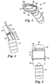
- A connector (12) for connecting an air source to a respirator (16), comprising a first conduit (18), a transition conduit (20) and a snap latch (22) attached thereto, characterised in that said snap latch (22) is a cantilevered snap latch (22) and includes a latch base (44) and a latch body (46) and said latch body (46) extends towards said first conduit (18) at an angle from said latch base (44) and includes a locking member disposed thereon for engaging a respirator.
- The connector of claim 1 further comprising an air supply hose attached to said transition conduit (20).
- The connector of claim 1 wherein the axis formed by the first air conduit (18), the transition conduit (20) and said air supply hose is nonlinear.
- The connector of claim 1 wherein the cantilevered snap latch (22) further comprises a reinforcing member.
- The connector of claim 1 wherein the transition conduit (20) comprises a circular base (40) and a flat body (42).
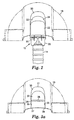
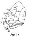
- A connector assembly for connecting a breathing tube to a respirator (16), comprising, a respirator (16) having a recessed receiving structure (24), characterised in that said recessed receiving structure (24) has a protruding member (28) for engaging a connector, and
the connector (12) of claim 1 for mating with the receiving structure (24). - The connector assembly of claim 6 wherein the respirator (16) includes a helmet.
- The connector assembly of claim 6 wherein the transition conduit (20) is generally rectangular in shape.
- The connector assembly of claim 6 wherein the transition conduit (20) includes a base (40) and body (42), wherein said body (40) extends at an angle away from said base (42).
- The connector assembly of claim 6 wherein said connector (12) is capable of withstanding a pull-off force of about 25 kilograms.
Applications Claiming Priority (3)
| Application Number | Priority Date | Filing Date | Title |
|---|---|---|---|
| US09/037,630 US6279573B1 (en) | 1998-03-10 | 1998-03-10 | Breathing tube connection for respiratory protective headgear |
| US37630 | 1998-03-10 | ||
| PCT/US1998/015180 WO1999046006A1 (en) | 1998-03-10 | 1998-07-22 | Breathing tube connection for respiratory protective headgear |
Publications (2)
| Publication Number | Publication Date |
|---|---|
| EP1062003A1 EP1062003A1 (en) | 2000-12-27 |
| EP1062003B1 true EP1062003B1 (en) | 2003-12-17 |
Family
ID=21895390
Family Applications (1)
| Application Number | Title | Priority Date | Filing Date |
|---|---|---|---|
| EP98935930A Expired - Lifetime EP1062003B1 (en) | 1998-03-10 | 1998-07-22 | Breathing tube connection for respiratory protective headgear |
Country Status (10)
| Country | Link |
|---|---|
| US (1) | US6279573B1 (en) |
| EP (1) | EP1062003B1 (en) |
| JP (1) | JP4087561B2 (en) |
| KR (1) | KR20010034585A (en) |
| AU (1) | AU8508198A (en) |
| BR (1) | BR9815723A (en) |
| CA (1) | CA2322135C (en) |
| DE (1) | DE69820678T2 (en) |
| ES (1) | ES2212321T3 (en) |
| WO (1) | WO1999046006A1 (en) |
Families Citing this family (20)
| Publication number | Priority date | Publication date | Assignee | Title |
|---|---|---|---|---|
| US7743767B2 (en) | 2002-04-23 | 2010-06-29 | Resmed Limited | Ergonomic and adjustable respiratory mask assembly with frame |
| US8997742B2 (en) | 2002-04-23 | 2015-04-07 | Resmed Limited | Ergonomic and adjustable respiratory mask assembly with cushion |
| AUPS315002A0 (en) * | 2002-06-25 | 2002-07-18 | Resmed Limited | Method & apparatus for control of appliance coupler retention and withdrawal forces |
| US6997187B2 (en) * | 2003-09-10 | 2006-02-14 | Innomed Technologies, Inc. | Nasal interface and system including ventilation insert |
| US9878117B2 (en) * | 2005-06-16 | 2018-01-30 | Resmed Limited | Swivel elbow for mask assembly |
| NZ591992A (en) | 2005-10-14 | 2012-11-30 | Resmed Ltd | Breathing mask with cushion attached to frame via lip of cushion engaging within recess between frame outer and inner walls, and guided in via angled protrusion of frame inner wall |
| US20090126739A1 (en) | 2005-10-25 | 2009-05-21 | Resmed Limited | Interchangeable Mask Assembly |
| US8517023B2 (en) | 2007-01-30 | 2013-08-27 | Resmed Limited | Mask system with interchangeable headgear connectors |
| EP2131928B1 (en) * | 2007-03-23 | 2017-08-09 | 3M Innovative Properties Company | Air delivery apparatus for respirator hood |
| PL2129443T3 (en) | 2007-03-23 | 2018-07-31 | 3M Innovative Properties Company | Respirator flow control apparatus and method |
| US8770190B2 (en) * | 2007-04-25 | 2014-07-08 | Resmed Limited | Connectors for connecting components of a breathing apparatus |
| CN102727975B (en) * | 2007-08-22 | 2016-03-30 | 纽约州立大学研究基金会 | Breathing gas supply and shared system and method thereof |
| AU2008307327B2 (en) * | 2007-10-05 | 2011-12-15 | 3M Innovative Properties Company | Respirator flow control apparatus and method |
| CN101909698B (en) | 2007-11-12 | 2014-03-12 | 3M创新有限公司 | Respirator assembly with air flow direction control |
| DE202009018972U1 (en) | 2008-03-04 | 2014-12-09 | Resmed Limited | mask system |
| US11331447B2 (en) | 2008-03-04 | 2022-05-17 | ResMed Pty Ltd | Mask system with snap-fit shroud |
| US9182064B2 (en) * | 2012-01-10 | 2015-11-10 | Carefusion Corporation | Connector structure and a connector structure of a sampling tube of a patient respiratory tubing |
| US9510626B2 (en) | 2013-02-01 | 2016-12-06 | 3M Innovative Properties Company | Sleeve-fit respirator cartridge |
| US10980305B2 (en) * | 2017-10-05 | 2021-04-20 | Honeywell International Inc. | Length adjustable shroud usable with helmet and earmuffs |
| DE202017006929U1 (en) | 2017-12-21 | 2018-11-16 | Dräger Safety AG & Co. KGaA | Breathing hose for a respiratory protective device and breathing apparatus |
Family Cites Families (30)
| Publication number | Priority date | Publication date | Assignee | Title |
|---|---|---|---|---|
| US999169A (en) * | 1910-11-10 | 1911-07-25 | Theodore N Jones | Hose-coupling. |
| DE410311C (en) * | 1924-04-04 | 1925-03-02 | Albert Hirth Dr Ing | Breathing mask |
| US2052046A (en) * | 1934-05-03 | 1936-08-25 | Rain Machine Ltd | Irrigation pipe coupling |
| US2453475A (en) * | 1945-09-14 | 1948-11-09 | Cornelius A Tobias | Resuscitation apparatus |
| US3736927A (en) | 1971-05-17 | 1973-06-05 | F Misaqi | Self-contained air purifier and conditioner unit |
| GB1495020A (en) | 1974-01-16 | 1977-12-14 | Nat Res Dev | Respirators |
| US3921223A (en) | 1974-06-12 | 1975-11-25 | David V Hoyecki | Air shield for welders and other craftsmen exposed to noxious fumes |
| DE2609034B2 (en) * | 1976-03-05 | 1981-04-30 | Drägerwerk AG, 2400 Lübeck | Connection for breathing apparatus |
| US4458719A (en) * | 1981-11-02 | 1984-07-10 | Imperial Clevite Inc. | Quick coupler service fitting |
| DE3211907A1 (en) | 1982-03-31 | 1983-10-20 | Drägerwerk AG, 2400 Lübeck | DEVICE QUICK CONNECTOR FOR RESPIRATORY MASKS |
| EP0130707B1 (en) * | 1983-06-07 | 1988-05-11 | Racal Safety Limited | Improvements in and relating to breathing apparatus |
| US4676236A (en) | 1983-09-09 | 1987-06-30 | Gentex Corporation | Helmet airflow system |
| US4669755A (en) * | 1986-09-29 | 1987-06-02 | The Singer Company | Hose connection for vacuum cleaner attachments |
| US4841953A (en) * | 1986-11-07 | 1989-06-27 | Dodrill Gregg W | Auxiliary supply system for a portable self-contained breathing apparatus |
| US4793342A (en) * | 1987-03-03 | 1988-12-27 | Terry McGovern Gaber | Emergency smoke hood and breathing mask |
| GB8809221D0 (en) | 1988-04-19 | 1988-05-25 | Safety Products Ltd | Improvements in/relating to safety visors |
| FR2646089B1 (en) | 1989-04-21 | 1991-09-27 | Fenzy Sa | INTERMEDIATE CONNECTION FOR BREATHING APPARATUS |
| US4996981A (en) | 1989-06-20 | 1991-03-05 | Allen Elenewski | Apparatus for removing condensate from a sealed face visor and for indicating a dangerous environmental temperature |
| US4997217A (en) * | 1990-05-10 | 1991-03-05 | Mine Safety Appliances Company | Breathing mask-hose coupling |
| US5150880A (en) * | 1991-02-14 | 1992-09-29 | Austin Jr George K | Valve assembly with flow control |
| FR2678707B1 (en) | 1991-07-05 | 1993-09-24 | Giat Ind Sa | DEVICE FOR QUICK CONNECTION OF A PNEUMATIC CIRCUIT UNDER RELATIVE PRESSURE ON AN APPARATUS FOR USE OR CONSUMPTION. |
| US5188400A (en) * | 1991-09-17 | 1993-02-23 | Stanley Aviation Corporation | Spring loaded coupling with positive spring latch |
| JPH061985U (en) * | 1992-06-15 | 1994-01-14 | サンデン株式会社 | Gas charge connector |
| US5394870A (en) * | 1993-09-03 | 1995-03-07 | Minnesota Mining And Manufacturing Company | Respirator blower unit housing with pommel-like strap support member comprising lower exterior support surface |
| US5427090A (en) | 1993-10-25 | 1995-06-27 | Hipskind; Donald W. | Portable breathing apparatus for an enclosed space |
| US5549104A (en) | 1994-09-16 | 1996-08-27 | E. D. Bullard Company | Air delivery and exhalation exhaust system for protective helmets |
| US5452713A (en) * | 1994-10-24 | 1995-09-26 | Tuthill Corporation | Portable ventilator with reversible inlet fitting |
| US5568946A (en) * | 1994-12-14 | 1996-10-29 | Itt Corporation | Squeeze-to-release quick connector with snap-in retainer |
| US5605145A (en) * | 1995-07-18 | 1997-02-25 | Puritan-Bennett Corporation | Microphone attenuation device for use in oxygen breathing masks |
| US5775323A (en) * | 1997-01-03 | 1998-07-07 | Tech-One, Inc. | Regulator conversion system |
-
1998
- 1998-03-10 US US09/037,630 patent/US6279573B1/en not_active Expired - Lifetime
- 1998-07-22 DE DE69820678T patent/DE69820678T2/en not_active Expired - Lifetime
- 1998-07-22 AU AU85081/98A patent/AU8508198A/en not_active Abandoned
- 1998-07-22 ES ES98935930T patent/ES2212321T3/en not_active Expired - Lifetime
- 1998-07-22 CA CA002322135A patent/CA2322135C/en not_active Expired - Fee Related
- 1998-07-22 BR BR9815723-0A patent/BR9815723A/en not_active IP Right Cessation
- 1998-07-22 JP JP2000535416A patent/JP4087561B2/en not_active Expired - Fee Related
- 1998-07-22 KR KR1020007010046A patent/KR20010034585A/en not_active Application Discontinuation
- 1998-07-22 EP EP98935930A patent/EP1062003B1/en not_active Expired - Lifetime
- 1998-07-22 WO PCT/US1998/015180 patent/WO1999046006A1/en active IP Right Grant
Also Published As
| Publication number | Publication date |
|---|---|
| WO1999046006A1 (en) | 1999-09-16 |
| KR20010034585A (en) | 2001-04-25 |
| JP2003518954A (en) | 2003-06-17 |
| AU8508198A (en) | 1999-09-27 |
| DE69820678T2 (en) | 2004-09-30 |
| CA2322135A1 (en) | 1999-09-16 |
| EP1062003A1 (en) | 2000-12-27 |
| CA2322135C (en) | 2007-12-04 |
| BR9815723A (en) | 2000-11-07 |
| ES2212321T3 (en) | 2004-07-16 |
| US6279573B1 (en) | 2001-08-28 |
| JP4087561B2 (en) | 2008-05-21 |
| DE69820678D1 (en) | 2004-01-29 |
Similar Documents
| Publication | Publication Date | Title |
|---|---|---|
| EP1062003B1 (en) | Breathing tube connection for respiratory protective headgear | |
| US11571591B2 (en) | Respirator with floating elastomeric sleeve | |
| CN108325108B (en) | Sleeve-fit filter cartridge | |
| JP4108929B2 (en) | Suspended mask device | |
| US20060231100A1 (en) | Supplied air respirator that has an adjustable length hose | |
| US5584286A (en) | Integrated breathing system | |
| US20050145249A1 (en) | Personal respiratory protection device that has a permanent or semi-permanent bayonet connection | |
| JP2008517710A (en) | Respiratory protection device with quick screwed clean air source attachment | |
| JP2022119807A (en) | Removable battery cartridge for facemask | |
| US20050145251A1 (en) | Respiratory component mounting assembly | |
| JP2018126547A (en) | Respiratory assembly including latching mechanism | |
| US5662627A (en) | Aspiration apparatus | |
| CN105764573B (en) | Tank attachment arrangement for self-contained breathing apparatus | |
| US20230142275A1 (en) | Full-face respiratory mask | |
| EP0756880B1 (en) | Improvements in or relating to breathing apparatus | |
| US20180111013A1 (en) | Quick release slide clip mechanism | |
| GB2330916A (en) | Air-conditioning system for safety goggles | |
| WO2021089626A1 (en) | Head mountable air respirator | |
| GB2074278A (en) | Fluid Conducting Spigot and Socket Connector Assembly | |
| US20060090755A1 (en) | Respirator fluid feed-line system and method of use | |
| CA1272351A (en) | Respirator harness assembly | |
| MXPA00003150A (en) | Drop-down face mask assembly |
Legal Events
| Date | Code | Title | Description |
|---|---|---|---|
| PUAI | Public reference made under article 153(3) epc to a published international application that has entered the european phase |
Free format text: ORIGINAL CODE: 0009012 |
|
| 17P | Request for examination filed |
Effective date: 20000922 |
|
| AK | Designated contracting states |
Kind code of ref document: A1 Designated state(s): DE ES FR GB IT NL |
|
| GRAH | Despatch of communication of intention to grant a patent |
Free format text: ORIGINAL CODE: EPIDOS IGRA |
|
| GRAS | Grant fee paid |
Free format text: ORIGINAL CODE: EPIDOSNIGR3 |
|
| GRAA | (expected) grant |
Free format text: ORIGINAL CODE: 0009210 |
|
| RAP1 | Party data changed (applicant data changed or rights of an application transferred) |
Owner name: MINNESSOTA MINING AND MANUFACTURING COMPANY |
|
| AK | Designated contracting states |
Kind code of ref document: B1 Designated state(s): DE ES FR GB IT NL |
|
| REG | Reference to a national code |
Ref country code: GB Ref legal event code: FG4D |
|
| REF | Corresponds to: |
Ref document number: 69820678 Country of ref document: DE Date of ref document: 20040129 Kind code of ref document: P |
|
| REG | Reference to a national code |
Ref country code: ES Ref legal event code: FG2A Ref document number: 2212321 Country of ref document: ES Kind code of ref document: T3 |
|
| ET | Fr: translation filed | ||
| PLBE | No opposition filed within time limit |
Free format text: ORIGINAL CODE: 0009261 |
|
| STAA | Information on the status of an ep patent application or granted ep patent |
Free format text: STATUS: NO OPPOSITION FILED WITHIN TIME LIMIT |
|
| 26N | No opposition filed |
Effective date: 20040920 |
|
| PGFP | Annual fee paid to national office [announced via postgrant information from national office to epo] |
Ref country code: NL Payment date: 20050629 Year of fee payment: 8 |
|
| PGFP | Annual fee paid to national office [announced via postgrant information from national office to epo] |
Ref country code: IT Payment date: 20060731 Year of fee payment: 9 |
|
| PG25 | Lapsed in a contracting state [announced via postgrant information from national office to epo] |
Ref country code: NL Free format text: LAPSE BECAUSE OF NON-PAYMENT OF DUE FEES Effective date: 20070201 |
|
| NLV4 | Nl: lapsed or anulled due to non-payment of the annual fee |
Effective date: 20070201 |
|
| PGFP | Annual fee paid to national office [announced via postgrant information from national office to epo] |
Ref country code: ES Payment date: 20080728 Year of fee payment: 11 |
|
| PGFP | Annual fee paid to national office [announced via postgrant information from national office to epo] |
Ref country code: FR Payment date: 20080729 Year of fee payment: 11 |
|
| PG25 | Lapsed in a contracting state [announced via postgrant information from national office to epo] |
Ref country code: IT Free format text: LAPSE BECAUSE OF NON-PAYMENT OF DUE FEES Effective date: 20070722 |
|
| REG | Reference to a national code |
Ref country code: FR Ref legal event code: ST Effective date: 20100331 |
|
| PG25 | Lapsed in a contracting state [announced via postgrant information from national office to epo] |
Ref country code: FR Free format text: LAPSE BECAUSE OF NON-PAYMENT OF DUE FEES Effective date: 20090731 |
|
| REG | Reference to a national code |
Ref country code: ES Ref legal event code: FD2A Effective date: 20090723 |
|
| PG25 | Lapsed in a contracting state [announced via postgrant information from national office to epo] |
Ref country code: ES Free format text: LAPSE BECAUSE OF NON-PAYMENT OF DUE FEES Effective date: 20090723 |
|
| PGFP | Annual fee paid to national office [announced via postgrant information from national office to epo] |
Ref country code: DE Payment date: 20100714 Year of fee payment: 13 |
|
| PGFP | Annual fee paid to national office [announced via postgrant information from national office to epo] |
Ref country code: GB Payment date: 20100721 Year of fee payment: 13 |
|
| GBPC | Gb: european patent ceased through non-payment of renewal fee |
Effective date: 20110722 |
|
| PG25 | Lapsed in a contracting state [announced via postgrant information from national office to epo] |
Ref country code: DE Free format text: LAPSE BECAUSE OF NON-PAYMENT OF DUE FEES Effective date: 20120201 |
|
| REG | Reference to a national code |
Ref country code: DE Ref legal event code: R119 Ref document number: 69820678 Country of ref document: DE Effective date: 20120201 |
|
| PG25 | Lapsed in a contracting state [announced via postgrant information from national office to epo] |
Ref country code: GB Free format text: LAPSE BECAUSE OF NON-PAYMENT OF DUE FEES Effective date: 20110722 |