EP1061996B1 - Apparatus for preferential outer retinal stimulation - Google Patents
Apparatus for preferential outer retinal stimulation Download PDFInfo
- Publication number
- EP1061996B1 EP1061996B1 EP99911299A EP99911299A EP1061996B1 EP 1061996 B1 EP1061996 B1 EP 1061996B1 EP 99911299 A EP99911299 A EP 99911299A EP 99911299 A EP99911299 A EP 99911299A EP 1061996 B1 EP1061996 B1 EP 1061996B1
- Authority
- EP
- European Patent Office
- Prior art keywords
- pulse
- retinal
- prosthesis
- duration
- stimulation
- Prior art date
- Legal status (The legal status is an assumption and is not a legal conclusion. Google has not performed a legal analysis and makes no representation as to the accuracy of the status listed.)
- Revoked
Links
Images


Classifications
-
- A—HUMAN NECESSITIES
- A61—MEDICAL OR VETERINARY SCIENCE; HYGIENE
- A61N—ELECTROTHERAPY; MAGNETOTHERAPY; RADIATION THERAPY; ULTRASOUND THERAPY
- A61N1/00—Electrotherapy; Circuits therefor
- A61N1/18—Applying electric currents by contact electrodes
- A61N1/32—Applying electric currents by contact electrodes alternating or intermittent currents
- A61N1/36—Applying electric currents by contact electrodes alternating or intermittent currents for stimulation
- A61N1/36046—Applying electric currents by contact electrodes alternating or intermittent currents for stimulation of the eye
Definitions
- This invention relates to outer retinal stimulation to produce phosphenes, and more particularly to a prosthesis for electrical stimulation of selected retinal cells to the exclusion of other retinal cells to produce phosphenes.
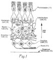
- the retinal basement membrane 10 (see FIG. 1) is at the surface of the retina, above the axons 11 which emanate from the retinal ganglion cells 12. These axons 11 which emanate from the retinal ganglion cells eventually come together and form the optic nerve (not shown) which projects to the brain.
- Beneath the retinal ganglion cells 12 are nerve cells involved in intermediate signal processing, such as amacrine cells 13, bipolar cells 14, interplexiform cells 15, and horizontal cells 16.
- the photoreceptor cells 17 At the back or outer layer of the retina. In degenerative diseases of the retina, such as retinitis pigmentosa, the photoreceptor cells 17 degrade, but the other nerve cells remain viable.
- the stimulation current capable of penetrating the retina to an excitation depth of approximately 30 micrometers is sufficient to depolarize the ganglion cells and evoke an action potential therefrom, the patient's perception of which is a focused phosphene. While de Juan, Jr. et al. '844 does not dwell on the stimulation waveform, this patent does teach that the waveform should preferably have an amplitude of not greater than about 0.3 to 3 milliampere and be biphasic having pulse duration of about 0.1 to about 2 milliseconds per phase, with a frequency of about 50 to 100 hertz.
- this positive pulse scheme requires a waveform pulse of duration between about 1 microsecond and about 500 microsecond having an amplitude of between about 1 microampere and about 500 microampere at a frequency of up to 1 kHz.
- Edell et al. '540 also teaches that the particular geometry of the electrode has a direct impact on the effectiveness of its method of stimulation of the ganglia soma and on the inadvertent and undesired stimulation of unrelated superficial axons from distant retinal ganglia soma.
- Edell et al. '540 therefore, requires specific geometry electrodes to perform the focused stimulation. However, the added complexity resulting from the criticality of placement and specific geometry of the electrodes, as well as the potential cellular effects of anodic (positive) stimulation and likely inadvertent stimulation of unrelated axons anyway, make this approach less desirable.
- a feature of the instant invention to provide a retinal prosthesis producing focused phosphenes which do not directly stimulate surface ganglia soma or proximal axon in the region of stimulation. More particularly, it is a feature of the instant invention to provide a retinal prosthesis generating focused phosphenes by stimulating retinal elements below the ganglion cells and their surface axons. Further, it is a feature of the instant invention to provide a retinal prosthesis producing focused phosphenes by stimulating intermediate retinal cells such as bipolar cells.
- the present invention is defined by the features of claim 1.
- Deeper intermediate retinal cellular electrical stimulation to the exclusion of direct ganglion cellular electrical stimulation is achieved by: a) positioning a stimulating electrode in the vicinity of retinal tissue; and b) applying a long duration stimulation signal to the electrode such that deeper intermediate retinal cells are preferentially stimulated over the retinal ganglion cells and proximal overlying surface axons.
- the long duration stimulation signal is a biphasic signal having a negative and a positive phase pulse which is applied in cathodic fashion.
- the duration of the long duration stimulation signal is greater than about 2 millisecond per phase pulse.
- the biphasic signal is adjusted to simulate a monophasic signal by adjusting the magnitude of the negative pulse in relation to positive pulse, and by adjusting the duration of the positive pulse in relation to the negative pulse to maintain approximately net zero charge introduction.
- the ratio of the negative pulse magnitude to the positive pulse magnitude is approximately 10:1 or greater.
- the retinal prosthesis generates a biphasic stimulation signal having a negative and a positive pulse and including an intra-pulse delay therebetween, each of the pulses having a duration equal to or greater than about 2 milliseconds and a magnitude, the biphasic stimulation signal having a relationship between the magnitude and the duration of the negative and the positive pulses such that the total charge supplied is approximately zero; and the biphasic stimulation signal is applied to the electrode in a cathodic fashion.
- retinal ganglion cells 12 lie close to the surface of the retina facing the vitreous cavity and send mostly unmyelinated axons 11 in a more superficial layer toward the optic disc (not shown).
- RGC axons As the human RGC axons exit the eye, they become myelinated and form the optic nerve.
- the cell bodies (somas) of these ganglion cells 12 are mapped over the surface of the retina in a manner which approximates the projection of the visual world onto the surface of the retina.
- axons 11 from distant sites overlie the individual ganglion cell bodies.
- a retinal prosthesis in accordance with the instant invention may be provided to produce focused phosphenes by deep retinal cell stimulation while totally avoiding the problem of inadvertent overlying proximal axon stimulation.
- This deep retinal cell stimulation also reveals advantages when the post-mortem histology of the entire retina in patients with retinitis pigmentosa (RP) is considered. This histology indicates a significant preservation of deeper (inner nuclear layer) retinal cells.
- the outer nuclear layer (photoreceptors) retained only about 5% of cells
- the inner nuclear layer (bipolar cells and others) retained about 78% of cells
- the RGC layer retained only about 30% of cells.
- the latency from stimulation was measured under varying stimulation conditions. This was done because a neuronal impulse initiated at the level of deeper retinal cells has to traverse at least one synapse before initiating a RGC action potential, resulting in longer RGC latencies than direct stimulation of the RGC. However, since the latencies in patients with RP cannot be measured when these patients are awake with normal eye movements, another measure for the target cell is needed. By measuring the response threshold for various stimulus durations, a strength-duration curve (S-D curve) can be constructed.
- S-D curve strength-duration curve
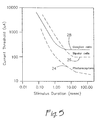
- FIG. 5 One such curve is illustrated as FIG. 5 and was generated using frog retina to establish the characteristics of the stimulation of each type of cell, the photoreceptors (trace 24), the bipolar cells (trace 26), and the ganglion cells (trace 28).
- the photoreceptors are by far the easiest retinal elements to stimulate, i.e., they have the lowest stimulation current thresholds.
- the photoreceptors are damaged, leaving only ganglion cells, bipolar cells, and other deeper intermediate retinal cells.
- these strength-duration curves have a hyperbolic shape and can be characterized by a time-constant and asymptote.
- Two terms often used to refer to these parameters are the chronaxie and rheobase.
- the chronaxie is uniquely determined by the element stimulated, and varies only slightly with the stimulus parameters and electrode geometry.
- the chronaxie is the pulse duration when the threshold stimulus is twice the rheobase and is actually In(2) x ⁇ .
- experimentation revealed a chronaxie of 6.1 +/- 2.8 millisecond.
- These long chronaxies found in RP patients seem to rule out the possibility of RGC stimulation with long pulses, and evidence that deeper cells, such as bipolar cells, are the target of longer duration stimulation pulses.
- Ganglion cells would be expected to have a chronaxie of less than 1 millisecond like other central nervous system neurons, whereas non-spiking deeper cells have longer chronaxies.
- long cathodic pulses offer the advantage to a retinal prosthesis of incorporating more of the natural retinal processing of the visual signal through the various retinal cells, while simultaneously avoiding inadvertent superficial axonal stimulation.
- the pulses are delivered with the cathodic pulse first as illustrated in FIG. 6.
- the delay between the two phases of current may be in relation to the pulse durations themselves, or may preferably be in the range of about 1 to 4 millisecond.
- the delay may also be timed to allow time for the stimulated deeper intermediate retinal cells to respond to the stimulation before equalizing the cellular charge by the introduction of the positive pulse. It should be noted, however, that while a preferred embodiment can utilize a biphasic pulse with an intra-pulse delay as just described, a biphasic pulse with no intra-pulse delay can also be utilized in practicing the instant invention.
- the relative height of the two pulses may be varied relative to one another.
- the amplitudes are adjusted so that one pulse is about 10 times the amplitude of the other as illustrated in FIG. 7, although one skilled in the art will recognize that other ratios can be utilized.
- the pulse durations are adjusted so that the injected charge is still balanced, that is to say, no net charge is injected.
- the present invention is used for focused phosphene generation through deeper intermediate retinal cellular electrical stimulation to the exclusion of direct ganglion cellular electrical stimulation by : a) positioning a stimulating electrode in the vicinity of the retinal tissue; and b) applying a long duration stimulation signal to the electrode such that deeper intermediate retinal cells are preferentially stimulated over the retinal ganglion cells and proximal overlying surface axons.
- the magnitude and duration of the stimulation signal are selected to preclude inadvertent stimulation of retinal ganglion cells by selecting a sufficiently long duration signal at a low current threshold below which the ganglion cells require for that duration signal (see FIG. 5).
- the stimulation signal is a biphasic signal as discussed above, preferably applied in a cathodic fashion (negative pulse first).
- the duration of the biphasic pulses of the long duration stimulation signal is greater than about 2 millisecond per phase pulse. In a further embodiment, the duration is greater than about 4 millisecond per phase pulse, and preferably greater than about 8 millisecond per phase pulse.
- the long duration stimulation signal can be composed of a train of these pulses. Additionally, the stimulation signal can be a low frequency signal having a frequency less than about 2 kilohertz. Preferably, the low frequency signal has a frequency of less than or equal to about 500 hertz, and preferably less than about 125 hertz. Furthermore, the stimulation signal can have a frequency of about 50 hertz or less.
- a preferred embodiment includes an intra-pulse delay.
- the duration of this intra-pulse delay may be in relation to the pulse duration or may be fixed.
- the intra-pulse delay ranges between about 1 to 4 millisecond.
Abstract
Description
- This invention relates to outer retinal stimulation to produce phosphenes, and more particularly to a prosthesis for electrical stimulation of selected retinal cells to the exclusion of other retinal cells to produce phosphenes.
- In 1755 LeRoy passed the discharge of a Leyden jar through the orbit of a man who was blind from cataract and the patient saw "flames passing rapidly downwards." Ever since, there has been a fascination with electrically elicited visual perception. The general concepts of electrical stimulation of retinal cells to produce these flashes of light or phosphenes has been known for quite some time. Based on these general principles, some early attempts at devising a prosthesis for aiding the visually impaired have included attaching electrodes to the head or eyelids of patients. While some of these early attempts met with some limited success, the phosphenes which were perceived were unfocused and could not approach actual vision restoration or simulation because of the gross, unfocused stimulation of the patient's eye or the optical nerve.
- As intraocular surgical techniques advanced, it became possible to apply a more focused stimulation on small groups of, and even on individual, retinal cells to generate focused phosphenes. This focused phosphene generation opens the possibility of true simulated vision generation by an implanted prosthesis within the eye itself. This has sparked renewed interest in developing methods and apparatuses to aid the visually impaired. Specifically, great effort has been expended in the area of focused stimulation of retinal elements proximal to degenerated photoreceptors which occur in certain forms of retinal blindness and which affect millions of people worldwide. However, while the surgical techniques had advanced to the point of allowing access to the retina, and while the structure and function of the retinal cells was understood, a complete understanding of the individual processes and mechanisms of simulated vision through retinal cellular stimulation was not completely understood in these early days.
- What was known about the structure of the retina is that the retinal basement membrane 10 (see FIG. 1) is at the surface of the retina, above the
axons 11 which emanate from theretinal ganglion cells 12. Theseaxons 11 which emanate from the retinal ganglion cells eventually come together and form the optic nerve (not shown) which projects to the brain. Beneath theretinal ganglion cells 12 are nerve cells involved in intermediate signal processing, such asamacrine cells 13,bipolar cells 14,interplexiform cells 15, andhorizontal cells 16. At the back or outer layer of the retina are thephotoreceptor cells 17. In degenerative diseases of the retina, such as retinitis pigmentosa, thephotoreceptor cells 17 degrade, but the other nerve cells remain viable. - Pioneering work by de Juan, Jr. et al. embodied in U.S. Patent 5,109,844 for RETINAL MICROSTIMULATION which issued May 5, 1992, provided the teaching for a method for stimulating the still viable retinal cells as well as for an apparatus for practicing this method, said teachings and disclosure being hereby incorporated by reference. As taught by de Juan, Jr. et al. '884, a focused stimulation of the
retinal ganglion cells 12 could produce focused phosphenes which, if stimulated by an array apparatus, could simulate vision. De Juan, Jr. et al. '844 also teaches that the stimulation current capable of penetrating the retina to an excitation depth of approximately 30 micrometers is sufficient to depolarize the ganglion cells and evoke an action potential therefrom, the patient's perception of which is a focused phosphene. While de Juan, Jr. et al. '844 does not dwell on the stimulation waveform, this patent does teach that the waveform should preferably have an amplitude of not greater than about 0.3 to 3 milliampere and be biphasic having pulse duration of about 0.1 to about 2 milliseconds per phase, with a frequency of about 50 to 100 hertz. - Since the axons from the ganglion cells traverse the surface of the retina on their way to form the optic nerve as discussed briefly above, it is recognized that to produce a focused phosphene, inadvertent stimulation of axons from distant ganglion cells which lie adjacent the target ganglion cells must be avoided. An inadvertent stimulation of adjacent axons from distant ganglion cells results in the perception of a wedge of light as opposed to a focused point of light and makes clear simulated vision through a retinal prosthesis difficult to obtain.
- One method of focused retinal cell stimulation which attempts to avoid the problem of inadvertent adjacent axon stimulation is described in Edell et al., U.S. Patent 5,411,540, issued May 2, 1995, for a METHOD AND APPARATUS FOR PREFERENTIAL NEURON STIMULATION. Edell et al. '540 describes the use of anodic (positive) stimulation to preferentially stimulate retinal ganglia somas while simultaneously avoiding unwanted stimulation of nearby unrelated axons to produce a focused phosphene. This reference describes that this positive pulse scheme requires a waveform pulse of duration between about 1 microsecond and about 500 microsecond having an amplitude of between about 1 microampere and about 500 microampere at a frequency of up to 1 kHz. Edell et al. '540 also teaches that the particular geometry of the electrode has a direct impact on the effectiveness of its method of stimulation of the ganglia soma and on the inadvertent and undesired stimulation of unrelated superficial axons from distant retinal ganglia soma. Edell et al. '540, therefore, requires specific geometry electrodes to perform the focused stimulation. However, the added complexity resulting from the criticality of placement and specific geometry of the electrodes, as well as the potential cellular effects of anodic (positive) stimulation and likely inadvertent stimulation of unrelated axons anyway, make this approach less desirable.
- It is an object of the instant invention to overcome at least some of the aforementioned and other known problems existing in the art. More particularly, it is an object of the instant invention to provide a new and improved device for producing focused phosphenes. Additionally, it is an object of the instant invention to provide a device for producing focused phosphenes which avoids the problems of inadvertent stimulation of proximal surface axons from distant ganglia soma.
- In view of these objects, it is a feature of the instant invention to provide a retinal prosthesis producing focused phosphenes which do not directly stimulate surface ganglia soma or proximal axon in the region of stimulation. More particularly, it is a feature of the instant invention to provide a retinal prosthesis generating focused phosphenes by stimulating retinal elements below the ganglion cells and their surface axons. Further, it is a feature of the instant invention to provide a retinal prosthesis producing focused phosphenes by stimulating intermediate retinal cells such as bipolar cells.
- It is therefore an aspect of the invention to provide a retinal prosthesis producing a focused phosphene by stimulating intermediate level retinal cells by varying the pulse duration of the stimulation signal. More particularly, it is an aspect of the instant invention to increase the duration of the stimulation signal pulse width to selectively directly stimulate only the deeper intermediate retinal cells. Further, it is an aspect of the instant invention to stimulate these deeper intermediate retinal cells by utilizing a vitreous-cathodic stimulation. Additionally, it is an aspect of the instant invention to utilize biphasic pulses. Furthermore, it is an aspect of the instant invention to make these biphasic pulses simulate cathodic monophasic pulses by using unequal amplitude phases. It is a further aspect of the instant invention to utilize an equal total charge in each phase to avoid damage to the underlying neural tissue from electrochemical effects.
- The present invention is defined by the features of
claim 1. - Deeper intermediate retinal cellular electrical stimulation to the exclusion of direct ganglion cellular electrical stimulation is achieved by: a) positioning a stimulating electrode in the vicinity of retinal tissue; and b) applying a long duration stimulation signal to the electrode such that deeper intermediate retinal cells are preferentially stimulated over the retinal ganglion cells and proximal overlying surface axons. The long duration stimulation signal is a biphasic signal having a negative and a positive phase pulse which is applied in cathodic fashion. To preferentially stimulate the deeper intermediate retinal elements, the duration of the long duration stimulation signal is greater than about 2 millisecond per phase pulse. In a highly preferred embodiment of the instant invention, the biphasic signal is adjusted to simulate a monophasic signal by adjusting the magnitude of the negative pulse in relation to positive pulse, and by adjusting the duration of the positive pulse in relation to the negative pulse to maintain approximately net zero charge introduction. Preferably, the ratio of the negative pulse magnitude to the positive pulse magnitude is approximately 10:1 or greater.
- In an alternate embodiment of the instant invention, the retinal prosthesis generates a biphasic stimulation signal having a negative and a positive pulse and including an intra-pulse delay therebetween, each of the pulses having a duration equal to or greater than about 2 milliseconds and a magnitude, the biphasic stimulation signal having a relationship between the magnitude and the duration of the negative and the positive pulses such that the total charge supplied is approximately zero; and the biphasic stimulation signal is applied to the electrode in a cathodic fashion.
- These and other aims, objectives, and advantages of the invention will become more apparent from the following detailed description while taken into conjunction with the accompanying drawings.
-
- FIG. 1 is a side sectional illustration of the retina in substantially anatomically correct form with the natural path of light in the retina indicated by the arrow;
- FIG. 2 is a simplified schematic representation of a region of neural retinal tissue being stimulated by an electrode placed on the vitreous surface of the retina and which is stimulating the ganglion cell axon, the stimulated portion being illustrated as a shaded area;
- FIG. 3 is a simplified schematic representation of a region of neural retinal tissue being stimulated by an electrode placed on the vitreous surface of the retina and which is stimulating the ganglion cell soma, the stimulated portion being illustrated as a shaded area;
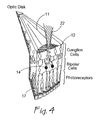
- FIG. 4 is a simplified schematic representation of a region of neural retinal tissue being stimulated in accordance with the instant invention by an electrode placed on the vitreous surface of the retina and which is stimulating the deeper intermediate retinal cells such as the bipolar cells, the stimulated portion being illustrated as a shaded area;
- FIG. 5 is a graphical illustration of an average of experimental data recorded in frog retinas of the stimulation strength versus stimulation pulse duration required to generate a biologic response for stimulation of different layers of the retina;
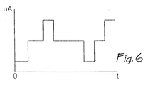
- FIG. 6 is a graphical signal chart illustrating an embodiment of the stimulation signal used to generate focused phosphenes by electrical stimulation of deeper intermediate retinal cells to the exclusion of the direct stimulation of the surface ganglion cells in accordance with the instant invention.
-
- While the invention is susceptible of various modifications and alternative constructions, certain illustrative embodiments thereof have been shown in the drawings and will be described below in detail. It should be understood, however, that there is no intention to limit the invention to the specific forms disclosed, but on the contrary, the intention is to cover all modifications, alternative constructions, and equivalents falling within the scope of the appended claims.
- To fully appreciate the instant invention, it is instructive to return to the simplified cross-sectional view of the retina illustrated in FIG. 1. In vertebrate animals, including humans, retinal ganglion cells 12 (RGCs) lie close to the surface of the retina facing the vitreous cavity and send mostly
unmyelinated axons 11 in a more superficial layer toward the optic disc (not shown). As the human RGC axons exit the eye, they become myelinated and form the optic nerve. The cell bodies (somas) of theseganglion cells 12 are mapped over the surface of the retina in a manner which approximates the projection of the visual world onto the surface of the retina. However, at any particular location on the surface of the retina,axons 11 from distant sites overlie the individual ganglion cell bodies. - If these
superficial passing fibers 11 were inadvertently stimulated by asurface electrode 22 while attempting to stimulate only proximal retinal ganglia soma, entire groups of ganglion cells 12a-d from a large area of the retina would be excited, illustrated in FIG. 2 as the shaded area labeled 18. The visual perception of such a resultant distributed stimulation would be in the form of a wedge of light, and not of a focused spot of light. On the other hand, if only theganglion cell 12 near the cell bodies could be preferentially stimulated, illustrated in FIG. 3 as the shaded area labeled 20, the visual perception of a focal spot (focused phosphene) would be expected. However, such selected stimulation of only the ganglion cell without also inadvertently stimulating the proximal overlyingsurface axons 11 is difficult as discussed above. - In accordance with the instant invention, however, direct stimulation of the ganglion cells and the problem of inadvertent stimulation of the overlying surface axons is avoided by electrical stimulation of deeper retinal cells, such as the
bipolar cells 14 or other deeper retinal cells illustrated in FIG. 4. The visual perception of this type of retinal stimulation is also a focal spot, although slightly larger than that which might be produced by stimulation of only a single ganglion cell. However, the focal spot diameter is sufficiently small to allow use in a retinal prosthesis, while avoiding all of the problems associated with surface ganglion stimulation and inadvertent proximal axon stimulation. It should be noted that the stimulatingelectrode 22 in each of FIGs. 2, 3, and 4 is illustrated schematically only as its particular configuration forms no part of this invention. - In developing such a deep retinal cellular stimulation method of the instant invention, it was discovered that, unlike other neural systems of the body, the time constants of retinal cells are significantly different from one another, which has a profound effect on the electrically elicited retinal responses. Where cells with different time-constants are in close physical proximity, for example, nerve vs. muscle, it has been observed that long time-constant cells are stimulated preferentially with long pulses whereas cells with short time-constants are stimulated preferentially with short pulses.
- Through experimentation the inventors have determined that, in the retina, short stimulus durations directly stimulate retinal ganglion cells (RGCs) while longer stimulus pulses target deeper cell to the exclusion of the surface RGCs and the proximal axons. With such a recognition, a retinal prosthesis in accordance with the instant invention may be provided to produce focused phosphenes by deep retinal cell stimulation while totally avoiding the problem of inadvertent overlying proximal axon stimulation. This deep retinal cell stimulation also reveals advantages when the post-mortem histology of the entire retina in patients with retinitis pigmentosa (RP) is considered. This histology indicates a significant preservation of deeper (inner nuclear layer) retinal cells. In the most severe cases of RP in patients with no light perception at all, the outer nuclear layer (photoreceptors) retained only about 5% of cells, the inner nuclear layer (bipolar cells and others) retained about 78% of cells, and the RGC layer retained only about 30% of cells. Thus the stimulation of this vastly more populated region containing many more active cells significantly improves the ability of a retinal prosthesis to enhance or produce simulated vision in patients suffering from RP or other visual degenerative conditions.
- To isolate the stimulation parameters to allow preferential stimulation of these deeper retinal cells, the latency from stimulation was measured under varying stimulation conditions. This was done because a neuronal impulse initiated at the level of deeper retinal cells has to traverse at least one synapse before initiating a RGC action potential, resulting in longer RGC latencies than direct stimulation of the RGC. However, since the latencies in patients with RP cannot be measured when these patients are awake with normal eye movements, another measure for the target cell is needed. By measuring the response threshold for various stimulus durations, a strength-duration curve (S-D curve) can be constructed.
- One such curve is illustrated as FIG. 5 and was generated using frog retina to establish the characteristics of the stimulation of each type of cell, the photoreceptors (trace 24), the bipolar cells (trace 26), and the ganglion cells (trace 28). As may be seen, the photoreceptors are by far the easiest retinal elements to stimulate, i.e., they have the lowest stimulation current thresholds. In certain diseases called outer retinal degenerations, however, the photoreceptors are damaged, leaving only ganglion cells, bipolar cells, and other deeper intermediate retinal cells. In cases of outer retinal degeneration, it is possible to select ganglion cells by using short duration pulses. In accordance with the instant invention, it is possible to stimulate deeper retinal cells by using longer duration stimuli. As the relationship depicted in FIG. 5 illustrates, this longer stimuli can be accomplished at reduced current threshold levels as well, which may seem counterintuitive due to the increased distance from the source of stimulation to the deeper retinal cells.
- For neurons, these strength-duration curves have a hyperbolic shape and can be characterized by a time-constant and asymptote. Two terms often used to refer to these parameters are the chronaxie and rheobase. The chronaxie is uniquely determined by the element stimulated, and varies only slightly with the stimulus parameters and electrode geometry. To determine the time-constant and rheobase from actual data, the strength-duration curve is fit using a weighted Marquardt-Levenberg algorithm to the following equation:
- With regard to the stimulation pulses, it is important to deliver balanced biphasic current pulses to patients to reduce the biologically harmful product of electrochemical reactions. According to a preferred embodiment of the instant invention, the pulses are delivered with the cathodic pulse first as illustrated in FIG. 6. The delay between the two phases of current (intra-pulse) may be in relation to the pulse durations themselves, or may preferably be in the range of about 1 to 4 millisecond. The delay may also be timed to allow time for the stimulated deeper intermediate retinal cells to respond to the stimulation before equalizing the cellular charge by the introduction of the positive pulse. It should be noted, however, that while a preferred embodiment can utilize a biphasic pulse with an intra-pulse delay as just described, a biphasic pulse with no intra-pulse delay can also be utilized in practicing the instant invention.
- Additionally, to effect monophasic stimulation (simulated monophasic stimulation), the relative height of the two pulses may be varied relative to one another. The larger the relative difference in magnitude, the more closely monophasic type stimulation is simulated. Preferably, the amplitudes are adjusted so that one pulse is about 10 times the amplitude of the other as illustrated in FIG. 7, although one skilled in the art will recognize that other ratios can be utilized. When this type of simulated monophasic stimulation is utilized, the pulse durations are adjusted so that the injected charge is still balanced, that is to say, no net charge is injected. The present invention is used for focused phosphene generation through deeper intermediate retinal cellular electrical stimulation to the exclusion of direct ganglion cellular electrical stimulation by : a) positioning a stimulating electrode in the vicinity of the retinal tissue; and b) applying a long duration stimulation signal to the electrode such that deeper intermediate retinal cells are preferentially stimulated over the retinal ganglion cells and proximal overlying surface axons. The magnitude and duration of the stimulation signal are selected to preclude inadvertent stimulation of retinal ganglion cells by selecting a sufficiently long duration signal at a low current threshold below which the ganglion cells require for that duration signal (see FIG. 5). The stimulation signal is a biphasic signal as discussed above, preferably applied in a cathodic fashion (negative pulse first).
- The duration of the biphasic pulses of the long duration stimulation signal is greater than about 2 millisecond per phase pulse. In a further embodiment, the duration is greater than about 4 millisecond per phase pulse, and preferably greater than about 8 millisecond per phase pulse. The long duration stimulation signal can be composed of a train of these pulses. Additionally, the stimulation signal can be a low frequency signal having a frequency less than about 2 kilohertz. Preferably, the low frequency signal has a frequency of less than or equal to about 500 hertz, and preferably less than about 125 hertz. Furthermore, the stimulation signal can have a frequency of about 50 hertz or less.
- Additionally, a preferred embodiment includes an intra-pulse delay. The duration of this intra-pulse delay may be in relation to the pulse duration or may be fixed. Preferably, the intra-pulse delay ranges between about 1 to 4 millisecond.
- Numerous modifications and alternative embodiments of the invention will be apparent to those skilled in the art in view of the foregoing description. Accordingly, this description is to be construed as illustrative only and is for the purpose of teaching those skilled in the art the best mode for carrying out the invention. The details of the structure and architecture may be varied substantially without departing from the scope of the appended claims .
Claims (14)
- A retinal prosthesis comprising:At least one electrode to be positioned in the vicinity of retinal tissue; andmeans for applying a long duration stimulation signal to the at least one electrode such that deeper intermediate retinal cells are preferentially stimulated over the retinal ganglion cells and proximal overlying surface axons, wherein the long duration stimulation signal is a biphasic signal having a negative and a positive phase pulse and wherein the duration of the long duration stimulation signal is greater than about 2 millisecond per phase pulse.
- The prosthesis of claim 1, wherein said means for applying a long duration stimulation signal comprises means for applying the long duration stimulation signal in cathodic fashion.
- The prosthesis of claim 1, wherein the duration of the long duration stimulation signal is greater than about 4 millisecond per phase pulse.
- The prosthesis of claim 1, wherein the duration of the long duration stimulation signal is greater than about 8 millisecond per phase pulse.
- The prosthesis of claim 1, wherein said means for applying a long duration stimulation signal comprises a means for applying a train of said biphasic signals.
- The prosthesis of claim 1, wherein said biphasic signal includes an intra-pulse delay.
- The prosthesis of claim 6, wherein said intra-pulse delay is in relation to a duration of said negative pulse.
- The prosthesis of claim 6, wherein said intra-pulse delay is in the range of about 1 to 4 millisecond.
- The prosthesis of claim 1, wherein said means for applying a long duration stimulation signal comprises means for adjusting said biphasic signal to simulate a monophasic signal.
- The prosthesis of claim 9, wherein said means for adjusting said biphasic signal comprises:means for adjusting a magnitude of said negative pulse in relation to said positive pulse; andmeans for adjusting a duration of said positive pulse in relation to said negative pulse to maintain approximately net zero charge introduction.
- The prosthesis of claim 10, wherein said means for adjusting a magnitude of said negative pulse in relation to said positive pulse increases the magnitude of the negative pulse by a ratio of approximately 10:1 to the positive pulse.
- The prosthesis of claim 1, wherein the long duration stimulation signal is a periodic waveform having a frequency less than or equal to about 50 hertz.
- The prosthesis of claim 1, wherein the long duration stimulation signal has a duration and a magnitude selected to preclude inadvertent stimulation of retinal ganglion cells.
- The retinal prosthesis of claim 1 wherein
said a biphasic stimulation signal having a negative and a positive pulse includes an intra-pulse delay therebetween, each of said pulses has a duration greater than about 2 milliseconds and a magnitude, said biphasic stimulation signal has a relationship between said magnitude and said duration of said negative and said positive pulses such that the total charge supplied is approximately zero; and further comprising means for applying said biphasic stimulation signal to said electrode in a cathodic fashion.
Applications Claiming Priority (3)
| Application Number | Priority Date | Filing Date | Title |
|---|---|---|---|
| US09/041,932 US5944747A (en) | 1998-03-13 | 1998-03-13 | Method for preferential outer retinal stimulation |
| US41932 | 1998-03-13 | ||
| PCT/US1999/005259 WO1999046001A1 (en) | 1998-03-13 | 1999-03-11 | Method for preferential outer retinal stimulation |
Publications (2)
| Publication Number | Publication Date |
|---|---|
| EP1061996A1 EP1061996A1 (en) | 2000-12-27 |
| EP1061996B1 true EP1061996B1 (en) | 2005-01-19 |
Family
ID=21919111
Family Applications (1)
| Application Number | Title | Priority Date | Filing Date |
|---|---|---|---|
| EP99911299A Revoked EP1061996B1 (en) | 1998-03-13 | 1999-03-11 | Apparatus for preferential outer retinal stimulation |
Country Status (9)
| Country | Link |
|---|---|
| US (1) | US5944747A (en) |
| EP (1) | EP1061996B1 (en) |
| JP (1) | JP3929701B2 (en) |
| AT (1) | ATE287277T1 (en) |
| AU (1) | AU739523B2 (en) |
| CA (1) | CA2323551C (en) |
| DE (1) | DE69923296T2 (en) |
| ES (1) | ES2235468T3 (en) |
| WO (1) | WO1999046001A1 (en) |
Cited By (1)
| Publication number | Priority date | Publication date | Assignee | Title |
|---|---|---|---|---|
| US7981062B2 (en) | 2001-06-29 | 2011-07-19 | Imi Intelligent Medical Implants Ag | Mechanically activated objects for treatment of degenerative retinal disease |
Families Citing this family (92)
| Publication number | Priority date | Publication date | Assignee | Title |
|---|---|---|---|---|
| US6324429B1 (en) * | 1998-05-08 | 2001-11-27 | Massachusetts Eye And Ear Infirmary | Chronically implantable retinal prosthesis |
| US6507758B1 (en) | 1999-03-24 | 2003-01-14 | Second Sight, Llc | Logarithmic light intensifier for use with photoreceptor-based implanted retinal prosthetics and those prosthetics |
| EP1864690A3 (en) * | 1999-03-24 | 2008-01-02 | Second Sight Medical Products, Inc. | Logarithmic light intensifier for use with photoreceptorbased implanted retinal prosthetics and those prosthetics |
| US20040039401A1 (en) * | 2000-03-31 | 2004-02-26 | Chow Alan Y. | Implant instrument |
| US6389317B1 (en) * | 2000-03-31 | 2002-05-14 | Optobionics Corporation | Multi-phasic microphotodetector retinal implant with variable voltage and current capability |
| US6427087B1 (en) | 2000-05-04 | 2002-07-30 | Optobionics Corporation | Artificial retina device with stimulating and ground return electrodes disposed on opposite sides of the neuroretina and method of attachment |
| US7043129B2 (en) * | 2000-06-16 | 2006-05-09 | Wayne State University | Wide bandgap semiconductor waveguide structures |
| US6848295B2 (en) * | 2002-04-17 | 2005-02-01 | Wayne State University | Acoustic wave sensor apparatus, method and system using wide bandgap materials |
| US6970745B2 (en) * | 2000-08-09 | 2005-11-29 | The United States Of America As Represented By The Secretary Of The Navy | Microelectronic stimulator array for stimulating nerve tissue |
| US6647297B2 (en) * | 2000-08-09 | 2003-11-11 | The United States Of America As Represented By The Secretary Of The Navy | Permanent retinal implant device |
| US6560490B2 (en) | 2000-09-26 | 2003-05-06 | Case Western Reserve University | Waveforms for selective stimulation of central nervous system neurons |
| US7103416B2 (en) * | 2001-01-16 | 2006-09-05 | Second Sight Medical Products, Inc. | Visual prosthesis including enhanced receiving and stimulating portion |
| US7149586B2 (en) * | 2002-03-28 | 2006-12-12 | Second Sight Medical Products, Inc. | Variable pitch electrode array |
| US7037943B2 (en) | 2001-04-10 | 2006-05-02 | Optobionics Corporation | Retinal treatment method |
| AU2002316347A1 (en) * | 2001-06-22 | 2003-01-08 | Ut-Battelle, Llc | Modulating photoreactivity in a cell |
| US20050004625A1 (en) * | 2001-06-29 | 2005-01-06 | Chow Alan Y. | Treatment of degenerative retinal disease via electrical stimulation of surface structures |
| US7031776B2 (en) * | 2001-06-29 | 2006-04-18 | Optobionics | Methods for improving damaged retinal cell function |
| DE10151650A1 (en) * | 2001-10-17 | 2003-05-08 | Univ Eberhard Karls | Electrode arrangement for electrical stimulation of biological material and multi-electrode array for use in such |
| WO2003061537A1 (en) * | 2002-01-17 | 2003-07-31 | Masachusetts Eye And Ear Infirmary | Minimally invasive retinal prosthesis |
| US6853075B2 (en) * | 2003-01-28 | 2005-02-08 | Wayne State University | Self-assembled nanobump array stuctures and a method to fabricate such structures |
| US20040144927A1 (en) * | 2003-01-28 | 2004-07-29 | Auner Gregory W. | Microsystems arrays for digital radiation imaging and signal processing and method for making microsystem arrays |
| US7483748B2 (en) * | 2002-04-26 | 2009-01-27 | Medtronic, Inc. | Programmable waveform pulses for an implantable medical device |
| US20030204222A1 (en) * | 2002-04-26 | 2003-10-30 | Medtronic, Inc. | Recharge delay for an implantable medical device |
| WO2004009022A2 (en) | 2002-07-18 | 2004-01-29 | The General Hospital Corp. | Method for augmenting vision in persons suffering from photoreceptor cell degeneration |
| US7565202B2 (en) * | 2002-07-30 | 2009-07-21 | Second Sight Medical Products, Inc. | Field focusing and mapping in an electrode array |
| US7574263B2 (en) * | 2003-01-31 | 2009-08-11 | Second Sight Medical Products, Inc. | Pixel re-mapping for visual prosthesis |
| US20060265057A1 (en) * | 2003-01-31 | 2006-11-23 | Greenberg Robert J | Field focusing and mapping in an electrode array |
| US8014878B2 (en) * | 2005-04-28 | 2011-09-06 | Second Sight Medical Products, Inc. | Flexible circuit electrode array |
| US8131375B2 (en) * | 2003-03-21 | 2012-03-06 | Second Sight Medical Products, Inc. | Trans-retinal flexible circuit electrode array |
| US7321796B2 (en) * | 2003-05-01 | 2008-01-22 | California Institute Of Technology | Method and system for training a visual prosthesis |
| US8260428B2 (en) * | 2003-05-01 | 2012-09-04 | California Institute Of Technology | Method and system for training a visual prosthesis |
| WO2005077452A1 (en) * | 2004-02-06 | 2005-08-25 | Scyfix Llc | Treatment of vision disorders using electrical, light, and/or sound energy |
| US8103352B2 (en) | 2004-12-03 | 2012-01-24 | Second Sight Medical Products, Inc. | Mimicking neural coding in retinal ganglion cells with short pulse electrical stimulation |
| US7571004B2 (en) | 2005-01-26 | 2009-08-04 | Second Sight Medical Products, Inc. | Neural stimulation for increased persistence |
| JP2008529684A (en) * | 2005-02-16 | 2008-08-07 | セカンド サイト メディカル プロダクツ インコーポレイテッド | Neural stimulation with increased persistence |
| EP2089100B1 (en) | 2005-04-28 | 2015-05-27 | Second Sight Medical Products, Inc. | Flexible circuit electrode array |
| JP4873897B2 (en) * | 2005-07-29 | 2012-02-08 | 株式会社ニデック | Visual reproduction assist device |
| US9913985B2 (en) * | 2006-04-28 | 2018-03-13 | Second Sight Medical Products, Inc. | Method and apparatus to provide safety checks for neural stimulation |
| US8457752B2 (en) * | 2005-09-16 | 2013-06-04 | Second Sight Medical Products, Inc. | Neural stimulation for increased contrast |
| US7877866B1 (en) * | 2005-10-26 | 2011-02-01 | Second Sight Medical Products, Inc. | Flexible circuit electrode array and method of manufacturing the same |
| US7610098B2 (en) * | 2005-12-20 | 2009-10-27 | Imi Intelligent Medical Implants Ag | Charge-integrating retinal prosthesis and method |
| US7914842B1 (en) | 2006-02-10 | 2011-03-29 | Second Sight Medical Products, Inc | Method of manufacturing a flexible circuit electrode array |
| JP4969882B2 (en) * | 2006-03-24 | 2012-07-04 | 株式会社ニデック | Visual reproduction assist device |
| EP2015834B1 (en) * | 2006-04-28 | 2017-06-14 | Second Sight Medical Products, Inc. | Visual prosthesis fitting |
| US8457754B2 (en) * | 2006-06-16 | 2013-06-04 | Second Sight Medical Products, Inc. | Apparatus and method for electrical stimulation of human neurons |
| US8311634B2 (en) * | 2006-06-16 | 2012-11-13 | Second Sight Medical Products Inc. | Apparatus and method for electrical stimulation of human retina |
| EP2046442B1 (en) | 2006-06-21 | 2017-01-25 | Second Sight Medical Products, Inc. | Flexible circuit electrode array with at least one tack opening |
| WO2008011096A2 (en) * | 2006-07-20 | 2008-01-24 | Second Sight Medical Products, Inc. | Apparatus and method for visual stimulation indication |
| US9764134B2 (en) * | 2006-07-28 | 2017-09-19 | Second Sight Medical Products, Inc. | Visual prosthesis |
| US7831309B1 (en) | 2006-12-06 | 2010-11-09 | University Of Southern California | Implants based on bipolar metal oxide semiconductor (MOS) electronics |
| AU2007338864B2 (en) * | 2006-12-22 | 2012-02-02 | Second Sight Medical Products, Inc. | Visual prosthetic apparatus for retinal stimulation |
| US8700167B2 (en) * | 2006-12-22 | 2014-04-15 | Ebs Technologies Gmbh | Apparatus and method for stimulating a brain of a person |
| DE202006021009U1 (en) | 2006-12-22 | 2012-01-05 | Ebs Technologies Gmbh | Device for stimulating the brain of a person |
| US20080183242A1 (en) * | 2007-01-29 | 2008-07-31 | Nidek Co., Ltd. | Electrical stimulation method for vision improvement |
| JP4959377B2 (en) * | 2007-02-28 | 2012-06-20 | 株式会社ニデック | Visual reproduction assist device |
| US8798756B2 (en) * | 2007-11-07 | 2014-08-05 | Second Sight Medical Products, Inc. | Video processing unit for a visual prosthetic apparatus |
| US8195303B2 (en) * | 2007-11-07 | 2012-06-05 | Second Sight Medical Products, Inc. | Video processing unit for a visual prosthetic apparatus |
| US8195302B2 (en) * | 2007-11-07 | 2012-06-05 | Second Sight Medical Products, Inc. | Video processing unit for a visual prosthetic apparatus |
| US10022558B1 (en) | 2008-01-07 | 2018-07-17 | Salutaris Medical Devices, Inc. | Methods and devices for minimally-invasive delivery of radiation to the eye |
| US9873001B2 (en) | 2008-01-07 | 2018-01-23 | Salutaris Medical Devices, Inc. | Methods and devices for minimally-invasive delivery of radiation to the eye |
| US8608632B1 (en) | 2009-07-03 | 2013-12-17 | Salutaris Medical Devices, Inc. | Methods and devices for minimally-invasive extraocular delivery of radiation and/or pharmaceutics to the posterior portion of the eye |
| KR101725117B1 (en) | 2008-01-07 | 2017-04-10 | 살루타리스 메디컬 디바이스즈, 인코퍼레이티드 | Devices for minimally-invasive extraocular delivery of radiation to the posterior portion of the eye |
| US8602959B1 (en) | 2010-05-21 | 2013-12-10 | Robert Park | Methods and devices for delivery of radiation to the posterior portion of the eye |
| US9056201B1 (en) | 2008-01-07 | 2015-06-16 | Salutaris Medical Devices, Inc. | Methods and devices for minimally-invasive delivery of radiation to the eye |
| US8340756B2 (en) * | 2008-08-05 | 2012-12-25 | Tony Picciano | Electronic stimulation device |
| USD691267S1 (en) | 2009-01-07 | 2013-10-08 | Salutaris Medical Devices, Inc. | Fixed-shape cannula for posterior delivery of radiation to eye |
| USD691268S1 (en) | 2009-01-07 | 2013-10-08 | Salutaris Medical Devices, Inc. | Fixed-shape cannula for posterior delivery of radiation to eye |
| USD691269S1 (en) | 2009-01-07 | 2013-10-08 | Salutaris Medical Devices, Inc. | Fixed-shape cannula for posterior delivery of radiation to an eye |
| USD691270S1 (en) | 2009-01-07 | 2013-10-08 | Salutaris Medical Devices, Inc. | Fixed-shape cannula for posterior delivery of radiation to an eye |
| US8150526B2 (en) | 2009-02-09 | 2012-04-03 | Nano-Retina, Inc. | Retinal prosthesis |
| US8428740B2 (en) | 2010-08-06 | 2013-04-23 | Nano-Retina, Inc. | Retinal prosthesis techniques |
| US8706243B2 (en) | 2009-02-09 | 2014-04-22 | Rainbow Medical Ltd. | Retinal prosthesis techniques |
| US8718784B2 (en) | 2010-01-14 | 2014-05-06 | Nano-Retina, Inc. | Penetrating electrodes for retinal stimulation |
| US8442641B2 (en) | 2010-08-06 | 2013-05-14 | Nano-Retina, Inc. | Retinal prosthesis techniques |
| US8571669B2 (en) | 2011-02-24 | 2013-10-29 | Nano-Retina, Inc. | Retinal prosthesis with efficient processing circuits |
| EP2686062A4 (en) * | 2011-03-18 | 2014-09-10 | Salk Inst For Biological Studi | Method for identification of retinal cell types using intrinsic properties |
| US9370417B2 (en) | 2013-03-14 | 2016-06-21 | Nano-Retina, Inc. | Foveated retinal prosthesis |
| AU2014274232B2 (en) | 2013-05-28 | 2020-03-26 | Pixium Vision | Smart prosthesis for facilitating artificial vision using scene abstraction |
| US9474902B2 (en) | 2013-12-31 | 2016-10-25 | Nano Retina Ltd. | Wearable apparatus for delivery of power to a retinal prosthesis |
| US9331791B2 (en) | 2014-01-21 | 2016-05-03 | Nano Retina Ltd. | Transfer of power and data |
| US9808625B2 (en) | 2015-05-01 | 2017-11-07 | Second Sight Medical Products, Inc. | Spatial fitting by percept location tracking |
| WO2016183512A1 (en) | 2015-05-13 | 2016-11-17 | Second Sight Medical Productions, Inc. | Cortical visual prosthesis |
| USD814637S1 (en) | 2016-05-11 | 2018-04-03 | Salutaris Medical Devices, Inc. | Brachytherapy device |
| USD814638S1 (en) | 2016-05-11 | 2018-04-03 | Salutaris Medical Devices, Inc. | Brachytherapy device |
| USD815285S1 (en) | 2016-05-11 | 2018-04-10 | Salutaris Medical Devices, Inc. | Brachytherapy device |
| JP6804078B2 (en) * | 2016-08-26 | 2020-12-23 | 国立大学法人大阪大学 | Intraocular flash generator |
| USD808529S1 (en) | 2016-08-31 | 2018-01-23 | Salutaris Medical Devices, Inc. | Holder for a brachytherapy device |
| USD808528S1 (en) | 2016-08-31 | 2018-01-23 | Salutaris Medical Devices, Inc. | Holder for a brachytherapy device |
| EP3860703A1 (en) | 2018-10-01 | 2021-08-11 | Biovisics Medical, Inc. | System and methods for controlled electrical modulation for vision therapy |
| WO2020112980A2 (en) | 2018-11-30 | 2020-06-04 | Biovisics Medical, Llc | Head worn apparatuses for vision therapy |
| EP3952979A1 (en) | 2019-04-10 | 2022-02-16 | Biovisics Medical, Inc. | Systems and interfaces for ocular therapy |
| EP3983055A1 (en) | 2019-06-14 | 2022-04-20 | Biovisics Medical, Inc. | Wearable medical device |
Family Cites Families (22)
| Publication number | Priority date | Publication date | Assignee | Title |
|---|---|---|---|---|
| US4664117A (en) * | 1984-10-09 | 1987-05-12 | Beck Stephen C | Apparatus and method for generating phosphenes |
| US4979508A (en) * | 1984-10-09 | 1990-12-25 | Beck Stephen C | Apparatus for generating phosphenes |
| US4628933A (en) * | 1985-07-23 | 1986-12-16 | Michelson Robin P | Method and apparatus for visual prosthesis |
| US5117826A (en) * | 1987-02-02 | 1992-06-02 | Staodyn, Inc. | Combined nerve fiber and body tissue stimulation apparatus and method |
| US4918745A (en) * | 1987-10-09 | 1990-04-17 | Storz Instrument Company | Multi-channel cochlear implant system |
| EP0325201A3 (en) * | 1988-01-20 | 1990-01-31 | Etama Ag | Stimulating device to improve the sight of persons with a poor sight |
| US5159927A (en) * | 1989-07-26 | 1992-11-03 | Ferdinand Schmid | Visual prosthesis apparatus and method |
| US5024223A (en) * | 1989-08-08 | 1991-06-18 | Chow Alan Y | Artificial retina device |
| US5016633A (en) * | 1989-08-08 | 1991-05-21 | Chow Alan Y | Artificial retina device |
| RU1799577C (en) * | 1989-08-17 | 1993-03-07 | Межотраслевой научно-технический комплекс "Микрохирургия глаза" | Method for improving vision function affected by ophthalmic nerve and retina disease |
| US5109844A (en) * | 1990-10-11 | 1992-05-05 | Duke University | Retinal microstimulation |
| US5476494A (en) * | 1992-09-11 | 1995-12-19 | Massachusetts Institute Of Technology | Low pressure neural contact structure |
| US5556423A (en) * | 1993-05-03 | 1996-09-17 | Alan Y. Chow | Independent photoelectric artificial retina device and method of using same |
| US5397350A (en) * | 1993-05-03 | 1995-03-14 | Chow; Alan Y. | Independent photoelectric artificial retina device and method of using same |
| US5597381A (en) * | 1993-06-03 | 1997-01-28 | Massachusetts Eye And Ear Infirmary | Methods for epi-retinal implantation |
| US5411540A (en) * | 1993-06-03 | 1995-05-02 | Massachusetts Institute Of Technology | Method and apparatus for preferential neuron stimulation |
| US5804566A (en) * | 1993-08-26 | 1998-09-08 | The Regents Of The University Of California | Methods and devices for immunizing a host through administration of naked polynucleotides with encode allergenic peptides |
| CN1121039A (en) * | 1994-09-16 | 1996-04-24 | P·J·汤姆生 | A lift sensor |
| US5522864A (en) * | 1994-10-25 | 1996-06-04 | Wallace; Larry B. | Apparatus and method for ocular treatment |
| JPH08297465A (en) * | 1995-04-26 | 1996-11-12 | Hiroshi Yamamoto | Optic nerve video output device and its method |
| DE69636151T2 (en) * | 1995-06-06 | 2006-09-14 | Optobionics Corp., Naperville | Arrangement for irritation of the retina by means of adaptive imaging |
| US5554187A (en) * | 1995-08-18 | 1996-09-10 | Rizzo, Iii; Joseph | Medication dispensing intra-ocular lens system |
-
1998
- 1998-03-13 US US09/041,932 patent/US5944747A/en not_active Expired - Lifetime
-
1999
- 1999-03-11 AT AT99911299T patent/ATE287277T1/en active
- 1999-03-11 EP EP99911299A patent/EP1061996B1/en not_active Revoked
- 1999-03-11 CA CA002323551A patent/CA2323551C/en not_active Expired - Lifetime
- 1999-03-11 ES ES99911299T patent/ES2235468T3/en not_active Expired - Lifetime
- 1999-03-11 DE DE69923296T patent/DE69923296T2/en not_active Expired - Lifetime
- 1999-03-11 AU AU29976/99A patent/AU739523B2/en not_active Expired
- 1999-03-11 JP JP2000535412A patent/JP3929701B2/en not_active Expired - Lifetime
- 1999-03-11 WO PCT/US1999/005259 patent/WO1999046001A1/en active IP Right Grant
Cited By (1)
| Publication number | Priority date | Publication date | Assignee | Title |
|---|---|---|---|---|
| US7981062B2 (en) | 2001-06-29 | 2011-07-19 | Imi Intelligent Medical Implants Ag | Mechanically activated objects for treatment of degenerative retinal disease |
Also Published As
| Publication number | Publication date |
|---|---|
| WO1999046001A1 (en) | 1999-09-16 |
| ES2235468T3 (en) | 2005-07-01 |
| DE69923296T2 (en) | 2005-06-09 |
| AU2997699A (en) | 1999-09-27 |
| CA2323551A1 (en) | 1999-09-16 |
| EP1061996A1 (en) | 2000-12-27 |
| US5944747A (en) | 1999-08-31 |
| CA2323551C (en) | 2008-07-29 |
| AU739523B2 (en) | 2001-10-18 |
| DE69923296D1 (en) | 2005-02-24 |
| JP3929701B2 (en) | 2007-06-13 |
| JP2002505929A (en) | 2002-02-26 |
| ATE287277T1 (en) | 2005-02-15 |
Similar Documents
| Publication | Publication Date | Title |
|---|---|---|
| EP1061996B1 (en) | Apparatus for preferential outer retinal stimulation | |
| US8103352B2 (en) | Mimicking neural coding in retinal ganglion cells with short pulse electrical stimulation | |
| US9757563B2 (en) | Neural stimulation for increased persistence | |
| US7765009B2 (en) | Sub-threshold stimulation to precondition neurons for supra-threshold stimulation | |
| Rattay et al. | Effective electrode configuration for selective stimulation with inner eye prostheses | |
| US20100236062A1 (en) | Method and Apparatus for Visual Neural Stimulation | |
| Suzuki et al. | Comparison of electrical stimulation thresholds in normal and retinal degenerated mouse retina | |
| US8892211B2 (en) | System and method for selective retinal stimulation | |
| US10065036B2 (en) | Method for measuring stable and reproducible electrode-tissue impedance | |
| Jezernik et al. | Improving Stimulation, Recording, and Modeling Tools and Techniques for Retinal Implant Development | |
| Fried et al. | A Mechanism for Generating Precise Temporal Patterns of Activity Using Prosthetic Stimulation | |
| DE29924969U1 (en) | Method of producing focused phosphenes | |
| Cheng | Computational model of epirentinal stimulation |
Legal Events
| Date | Code | Title | Description |
|---|---|---|---|
| PUAI | Public reference made under article 153(3) epc to a published international application that has entered the european phase |
Free format text: ORIGINAL CODE: 0009012 |
|
| 17P | Request for examination filed |
Effective date: 20000926 |
|
| AK | Designated contracting states |
Kind code of ref document: A1 Designated state(s): AT BE CH CY DE DK ES FI FR GB GR IE IT LI LU MC NL PT SE |
|
| 17Q | First examination report despatched |
Effective date: 20010111 |
|
| GRAP | Despatch of communication of intention to grant a patent |
Free format text: ORIGINAL CODE: EPIDOSNIGR1 |
|
| RTI1 | Title (correction) |
Free format text: APPARATUS FOR PREFERENTIAL OUTER RETINAL STIMULATION |
|
| GRAS | Grant fee paid |
Free format text: ORIGINAL CODE: EPIDOSNIGR3 |
|
| GRAA | (expected) grant |
Free format text: ORIGINAL CODE: 0009210 |
|
| AK | Designated contracting states |
Kind code of ref document: B1 Designated state(s): AT BE CH CY DE DK ES FI FR GB GR IE IT LI LU MC NL PT SE |
|
| PG25 | Lapsed in a contracting state [announced via postgrant information from national office to epo] |
Ref country code: FI Free format text: LAPSE BECAUSE OF FAILURE TO SUBMIT A TRANSLATION OF THE DESCRIPTION OR TO PAY THE FEE WITHIN THE PRESCRIBED TIME-LIMIT Effective date: 20050119 |
|
| REG | Reference to a national code |
Ref country code: GB Ref legal event code: FG4D |
|
| RIN1 | Information on inventor provided before grant (corrected) |
Inventor name: DE JUAN, EUGENE, JR. Inventor name: HUMAYUN, MARK, S. Inventor name: GREENBERG, ROBERT J.,BUILDING A, |
|
| REG | Reference to a national code |
Ref country code: CH Ref legal event code: NV Representative=s name: BOVARD AG PATENTANWAELTE Ref country code: CH Ref legal event code: EP |
|
| REG | Reference to a national code |
Ref country code: IE Ref legal event code: FG4D |
|
| REF | Corresponds to: |
Ref document number: 69923296 Country of ref document: DE Date of ref document: 20050224 Kind code of ref document: P |
|
| PG25 | Lapsed in a contracting state [announced via postgrant information from national office to epo] |
Ref country code: IE Free format text: LAPSE BECAUSE OF NON-PAYMENT OF DUE FEES Effective date: 20050311 Ref country code: CY Free format text: LAPSE BECAUSE OF FAILURE TO SUBMIT A TRANSLATION OF THE DESCRIPTION OR TO PAY THE FEE WITHIN THE PRESCRIBED TIME-LIMIT Effective date: 20050311 |
|
| PG25 | Lapsed in a contracting state [announced via postgrant information from national office to epo] |
Ref country code: MC Free format text: LAPSE BECAUSE OF NON-PAYMENT OF DUE FEES Effective date: 20050331 |
|
| PG25 | Lapsed in a contracting state [announced via postgrant information from national office to epo] |
Ref country code: SE Free format text: LAPSE BECAUSE OF FAILURE TO SUBMIT A TRANSLATION OF THE DESCRIPTION OR TO PAY THE FEE WITHIN THE PRESCRIBED TIME-LIMIT Effective date: 20050419 Ref country code: GR Free format text: LAPSE BECAUSE OF FAILURE TO SUBMIT A TRANSLATION OF THE DESCRIPTION OR TO PAY THE FEE WITHIN THE PRESCRIBED TIME-LIMIT Effective date: 20050419 Ref country code: DK Free format text: LAPSE BECAUSE OF FAILURE TO SUBMIT A TRANSLATION OF THE DESCRIPTION OR TO PAY THE FEE WITHIN THE PRESCRIBED TIME-LIMIT Effective date: 20050419 |
|
| REG | Reference to a national code |
Ref country code: ES Ref legal event code: FG2A Ref document number: 2235468 Country of ref document: ES Kind code of ref document: T3 |
|
| PLBI | Opposition filed |
Free format text: ORIGINAL CODE: 0009260 |
|
| PLAX | Notice of opposition and request to file observation + time limit sent |
Free format text: ORIGINAL CODE: EPIDOSNOBS2 |
|
| 26 | Opposition filed |
Opponent name: IMI INTELLIGENT MEDICAL IMPLANTS AG Effective date: 20051018 |
|
| REG | Reference to a national code |
Ref country code: IE Ref legal event code: MM4A |
|
| ET | Fr: translation filed | ||
| NLR1 | Nl: opposition has been filed with the epo |
Opponent name: IMI INTELLIGENT MEDICAL IMPLANTS AG |
|
| PLAF | Information modified related to communication of a notice of opposition and request to file observations + time limit |
Free format text: ORIGINAL CODE: EPIDOSCOBS2 |
|
| PLAF | Information modified related to communication of a notice of opposition and request to file observations + time limit |
Free format text: ORIGINAL CODE: EPIDOSCOBS2 |
|
| PLBB | Reply of patent proprietor to notice(s) of opposition received |
Free format text: ORIGINAL CODE: EPIDOSNOBS3 |
|
| PLAH | Information related to despatch of examination report in opposition + time limit modified |
Free format text: ORIGINAL CODE: EPIDOSCORE2 |
|
| PLAY | Examination report in opposition despatched + time limit |
Free format text: ORIGINAL CODE: EPIDOSNORE2 |
|
| PLAH | Information related to despatch of examination report in opposition + time limit modified |
Free format text: ORIGINAL CODE: EPIDOSCORE2 |
|
| PLBC | Reply to examination report in opposition received |
Free format text: ORIGINAL CODE: EPIDOSNORE3 |
|
| PG25 | Lapsed in a contracting state [announced via postgrant information from national office to epo] |
Ref country code: PT Free format text: LAPSE BECAUSE OF NON-PAYMENT OF DUE FEES Effective date: 20050619 |
|
| PLCK | Communication despatched that opposition was rejected |
Free format text: ORIGINAL CODE: EPIDOSNREJ1 |
|
| PLAO | Information deleted related to despatch of communication that opposition is rejected |
Free format text: ORIGINAL CODE: EPIDOSDREJ1 |
|
| PLCK | Communication despatched that opposition was rejected |
Free format text: ORIGINAL CODE: EPIDOSNREJ1 |
|
| APBP | Date of receipt of notice of appeal recorded |
Free format text: ORIGINAL CODE: EPIDOSNNOA2O |
|
| APAH | Appeal reference modified |
Free format text: ORIGINAL CODE: EPIDOSCREFNO |
|
| APBQ | Date of receipt of statement of grounds of appeal recorded |
Free format text: ORIGINAL CODE: EPIDOSNNOA3O |
|
| PLAB | Opposition data, opponent's data or that of the opponent's representative modified |
Free format text: ORIGINAL CODE: 0009299OPPO |
|
| REG | Reference to a national code |
Ref country code: CH Ref legal event code: PFA Owner name: THE JOHNS HOPKINS UNIVERSITY Free format text: THE JOHNS HOPKINS UNIVERSITY#2024 EAST MONUMENT STREET, SUITE 2-100#BALTIMORE, MARYLAND 21205 (US) -TRANSFER TO- THE JOHNS HOPKINS UNIVERSITY#2024 EAST MONUMENT STREET, SUITE 2-100#BALTIMORE, MARYLAND 21205 (US) |
|
| PGFP | Annual fee paid to national office [announced via postgrant information from national office to epo] |
Ref country code: LU Payment date: 20120326 Year of fee payment: 14 Ref country code: CH Payment date: 20120326 Year of fee payment: 14 |
|
| PGFP | Annual fee paid to national office [announced via postgrant information from national office to epo] |
Ref country code: DE Payment date: 20120326 Year of fee payment: 14 |
|
| REG | Reference to a national code |
Ref country code: DE Ref legal event code: R103 Ref document number: 69923296 Country of ref document: DE Ref country code: DE Ref legal event code: R064 Ref document number: 69923296 Country of ref document: DE |
|
| PGFP | Annual fee paid to national office [announced via postgrant information from national office to epo] |
Ref country code: BE Payment date: 20120328 Year of fee payment: 14 Ref country code: GB Payment date: 20120320 Year of fee payment: 14 |
|
| PGFP | Annual fee paid to national office [announced via postgrant information from national office to epo] |
Ref country code: NL Payment date: 20120329 Year of fee payment: 14 |
|
| PGFP | Annual fee paid to national office [announced via postgrant information from national office to epo] |
Ref country code: FR Payment date: 20120413 Year of fee payment: 14 |
|
| APBU | Appeal procedure closed |
Free format text: ORIGINAL CODE: EPIDOSNNOA9O |
|
| PGFP | Annual fee paid to national office [announced via postgrant information from national office to epo] |
Ref country code: IT Payment date: 20120328 Year of fee payment: 14 |
|
| RDAF | Communication despatched that patent is revoked |
Free format text: ORIGINAL CODE: EPIDOSNREV1 |
|
| RDAG | Patent revoked |
Free format text: ORIGINAL CODE: 0009271 |
|
| STAA | Information on the status of an ep patent application or granted ep patent |
Free format text: STATUS: PATENT REVOKED |
|
| REG | Reference to a national code |
Ref country code: CH Ref legal event code: PL |
|
| 27W | Patent revoked |
Effective date: 20120615 |
|
| GBPR | Gb: patent revoked under art. 102 of the ep convention designating the uk as contracting state |
Effective date: 20120615 |
|
| PG25 | Lapsed in a contracting state [announced via postgrant information from national office to epo] |
Ref country code: LI Free format text: LAPSE BECAUSE OF THE APPLICANT RENOUNCES Effective date: 20050119 Ref country code: CH Free format text: LAPSE BECAUSE OF THE APPLICANT RENOUNCES Effective date: 20050119 |
|
| REG | Reference to a national code |
Ref country code: DE Ref legal event code: R107 Ref document number: 69923296 Country of ref document: DE Effective date: 20130228 |
|
| REG | Reference to a national code |
Ref country code: AT Ref legal event code: MA03 Ref document number: 287277 Country of ref document: AT Kind code of ref document: T Effective date: 20120615 |
|
| PGFP | Annual fee paid to national office [announced via postgrant information from national office to epo] |
Ref country code: AT Payment date: 20120221 Year of fee payment: 14 |
|
| PGFP | Annual fee paid to national office [announced via postgrant information from national office to epo] |
Ref country code: ES Payment date: 20120323 Year of fee payment: 14 |