EP1061460A2 - Partial image forming method and apparatus for filing documents - Google Patents
Partial image forming method and apparatus for filing documents Download PDFInfo
- Publication number
- EP1061460A2 EP1061460A2 EP00305100A EP00305100A EP1061460A2 EP 1061460 A2 EP1061460 A2 EP 1061460A2 EP 00305100 A EP00305100 A EP 00305100A EP 00305100 A EP00305100 A EP 00305100A EP 1061460 A2 EP1061460 A2 EP 1061460A2
- Authority
- EP
- European Patent Office
- Prior art keywords
- image
- character
- partial
- extracting
- character train
- Prior art date
- Legal status (The legal status is an assumption and is not a legal conclusion. Google has not performed a legal analysis and makes no representation as to the accuracy of the status listed.)
- Granted
Links
Images


Classifications
-
- G—PHYSICS
- G06—COMPUTING; CALCULATING OR COUNTING
- G06F—ELECTRIC DIGITAL DATA PROCESSING
- G06F16/00—Information retrieval; Database structures therefor; File system structures therefor
- G06F16/50—Information retrieval; Database structures therefor; File system structures therefor of still image data
- G06F16/51—Indexing; Data structures therefor; Storage structures
Definitions
- the present invention relates to reduced image forming method and apparatus which are suitable for an electric filing apparatus for searching, displaying, and printing image data of a document stored with relation to predetermined managing information, etc.
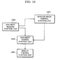
- Fig. 10 is a diagram showing a functional construction example of a general electric filing apparatus for displaying a reduced image in a document list and a search result list.
- the electric filing apparatus has: a document reading function unit 1000; a reduced image forming function unit 1001; a document storing function unit 1002; and a display control function unit 1003, as exemplified in Fig. 10.
- the document reading function unit 1000 reads image data of a document by a scanner device, etc. (not shown).
- the reduced image forming function unit 1001 forms image data which is reduced with a proper size by thinning out a dot, etc. from the image data of the document read by the document reading function unit 1000.
- the document storing function unit 1002 stores the image data of the document read by the document reading function unit 1000 and the reduced image data of the document formed by the reduced image forming function unit 1001, with the relation therebetween.
- the display control function unit 1003 controls an operation for displaying the image data of the document and the reduced image which are stored in the document storing function unit 1002, for instance, displays a document list based on the reduced image shown in Fig. 11.
- the outline of the document can be identified from the reduced image of the document, but only a layout of the whole document can be identified and a character written to the document cannot discriminated. This arises a problem that it is extremely difficult to identify a document having a similar layout and a document having no distinctive feature which has not large character and no figure from the reduced image.
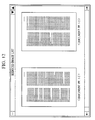
- a preferable example is a reduced displaying example of a patent specification shown in Fig. 12.
- the example indicates the reduced image of 2 pages in a publication of a US. patent application, and it is impossible to discriminate what is written in both of the pages displayed in the right and left in the least.
- the present invention is devised in view of the aforementioned problems. It is an object of the present invention to form a reduced image capable of easily identifying the contents of even a document having a similar layout and a document having no distinctive feature in case of displaying a list of documents and a search result list.
- a reduced image forming apparatus comprising:
- a reduced image forming apparatus comprising:
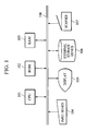
- Fig. 1 is a block diagram showing an outline of an apparatus construction of an electric filing apparatus according to the present embodiment.
- Reference numeral 101 denotes a CPU which executes various control operations in the electric filing apparatus on the basis of the a control program stored in an ROM 102 and an RAM 103; 102 the ROM which stores the control program executed by the CPU 101 and various data; and 103 the RAM which provides an area to store the control program executed by the CPU 101 and a work area of the CPU 101.
- Reference numeral 104 denotes an input device having a keyboard or pointing device; 105 a display which displays various images under the control operation by the CPU 101; 106 an external storage device which stores image data and a varieties of application programs; and 107 a scanner which reads an original image optically and converts the read image into digital data which is processable by the CPU 101.
- Fig. 2 is a block diagram showing a functional construction of the electric filing apparatus according to the present embodiment.
- reference numeral 1 denotes an image dividing process function unit; 2 a partial image extracting process function unit; 3 a reduced image combining process function unit; 4 a document registering function unit; 5 a filing device; 6 a display control function unit; 7 a selecting function unit; 8 an input device; 9 an output device; and 10 a document reading function unit.
- the CPU 101 executes the control program which is loaded in the RAM 103 from the external storage device 106 and controls the scanner 107 and external storage device 106, thereby realizing the function units.
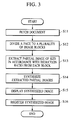
- Fig. 3 is a flowchart for explaining the operation of the electric filing apparatus according to the present embodiment. The operation of the present embodiment will be described with reference to Figs. 2 and 3 hereinbelow.
- the document reading function unit 10 inputs document image data as a processing target from the input device 8 (such as the scanner 107 and external storage device 106) and stores the data into the memory (RAM 103) (step S11).
- the document image data may be data of a 400dpi-resolution which is read by the scanner 107 in real time or may be data which is previously read and stored in the external storage device 106.
- the image dividing process function unit 1 uniformly divides the document image data stored in the RAM 103 by a predetermined dividing number, thereby dividing the document image data into a plurality of image blocks (step S12).
- an image 20 (one page of a publication of a US. patent application) of an A4 size is uniformly divided into four blocks, as shown in Fig. 4.
- Fig. 4 is a conceptual diagram showing the document image data stored in the RAM 103.
- the divided blocks are labeled as image blocks A, B, C, and D (21 to 24). It is a purpose of this division to extract features from the four portions in the uniform arrangement on the image.
- the partial image extracting process function unit 2 extracts a partial image having a predetermined amount (a predetermined size) from each image block which is divided by the image dividing process function unit 1(step S13). It is noted that the extracting amount is determined dependently upon a rate of the size of the reduced image on the display 105 and the size of the original image on paper.
- a plurality of reduced images are displayed in a reduced image list. If assuming that the size of an image is equal to about 5 cm, for example, on a 17inch-display, it is possible to display eight reduced images.
- An image corresponding to the A4 size has a width of about 20 cm, so that the reduction ratio is set to 1/4 one-dimensionally. That is, the reduction ratio is equal to 1/16 on the area. Accordingly, if extracting only an area of 1/16 from each image block shown in Fig. 4, the sum of width of four image blocks is equal to about 5 cm on the display.
- each image block is uniformly divided into sixteen partial images, as shown in Fig. 5, and the partial image is extracted from the image blocks one by one.
- the selecting function unit 7 is set to select the head partial image in each image block.
- Four partial images (501 to 504) as shown by hatched portions in Fig. 5 are extracted.
- the reduced image combining process function unit 3 vertically aligns the partial images extracted by the partial image extracting process function unit 2, thereby constructing one reduced image, as shown in Fig. 6, and stores the reduced image into the memory (RAM 103) (step S14).
- the constructed reduced image is composed of an extracted partial image 601 of an image block A21, an extracted partial image 602 of an image block B22, an extracted partial image 603 of an image block C23, and an extracted partial image 604 of an image block D24, in the descending order. Further, the thus-combined image is reduced within a range in capable of discriminating a character.
- the size capable of recognizing one character on the CRT is limited to about 2 mm every character width.
- the original used in the present embodiment is a publication of a US. patent application, and the size of one character is about 2mm on the paper.
- the image in this example is scanned by the scanner 107 having the 400dpi-resolution, the image is reduced to 1/4.
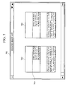
- the reduced image is displayed on a window 701 on a screen of the display 105 as reduced images (702, 703) via the display control function unit 6, as shown in Fig. 7.
- Fig. 7 shows to display the reduced image obtained by the processes.
- the document registering function unit 4 registers the document image data read by the document reading function unit 10 and the reduced image processed by the reduced image combining process function unit 3 into the file device 5 with relationship therebetween (step S16).
- the file device 5 stores the document image data and document managing information such as a keyword with a relation therebetween as a database.
- the display control function unit 6 controls an operation to display the image data in a character area stored in the file device 5 to the output device 9 (such as the display 105).
- the CRT is used as a display in the present embodiment, not only the CRT but also an LCD may be used if using them as a display.
- the image extracted from a plurality of areas in one page is reduced and indicated within a decidable range, so that the operator can discriminate the contents of the indicated document easily. That is, even with respect to a document having a similar layout or a document with no distinctive feature, so long as the reduced image is used, the character can be recognized throughout the document, though a part of the document is one part. Therefore, it is able to identify the document easily.
- a document has a margin and the publication of the US. patent application is set to have a margin of about 1/16 vertically.
- the selecting function unit 7 shown in the embodiment is set to uniquely select the head portion of each image block.
- a space portion is extracted in portions of the image blocks A21 and C23 as a result of the combination of the reduced images, as shown by 601 and 603 in Fig. 6.
- the quantity of information is decreased and the advantage is decreased to the half (no feature is extracted from the portions of the image blocks A21 and C23).
- Setting values of the selecting function unit 7 may be set to extract the partial images which are located at the second order from the head in the image blocks A21 and C23, and to extract the head partial images from the image blocks B22 and D24.
- hatched portions 801 to 804 shown in Fig. 8 become an extraction target. Consequently, with regard to a combined reduced-image as shown in Fig. 9, the partial image 801 in Fig. 8 becomes an extracted partial image 901; the partial image 802 in Fig. 8 an extracted partial image 902; the partial image 803 in Fig. 8 an extracted partial image 903; and the partial image 804 in Fig. 8 an extracted partial image 904.
- the quantity of information can be increased.
- Fig. 13 is a block diagram showing a functional construction of an electric filing apparatus according to the present embodiment.
- reference numeral 1300 denotes a character recognizing process function unit; 1301 a whole character train dividing process function unit; 1302 a partial character train extracting process function unit; 1303 a reduced image combining process function unit; 1304 a document registering function unit; 1305 a file device; 1306 a display control function unit; 1307 a selecting function unit; 1308 an input device; 1309 an output device; and 1310 a document reading function unit.
- the CPU 101 executes the control program loaded in the RAM 103 from the external storage device 106 and controls the scanner 107 and the external storage device 106, etc., thereby realizing the function units.
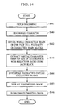
- Fig. 14 is a flowchart for explaining the operation of the electric filing apparatus according to the present embodiment. The operation according to the present embodiment will be described with reference to Figs. 13 and 14 hereinbelow.
- the document reading function unit 1310 inputs document image data as a processing target from the input device 1308 (such as the scanner 107 and external storage device 106) and stores the image data into the memory (RAM 103) (step S41).
- the document image data may be data of a 400dpi-resolution which is read by the scanner 107 in real time or may be data which is previously read and stored in the external storage device 106.
- the character recognizing process function unit 1300 reads an image from the memory (RAM 103) and outputs the recognized character. According to the present embodiment, in case of two or more spaces are successive, the character recognizing process function unit 1300 outputs only one space and outputs only one space in case of a carriage return line feed control code.
- the output by the character recognizing process function unit is obtained by coupling a character train as a set of sequent characters including no space by using a space. In other words, the output is a character train of the whole one page (step S40).
- the image processing function unit 1301 uniformly divides the character train stored in the RAM 103 by a predetermined dividing number, thereby dividing the character train into a plurality of character train blocks (step S42).
- an image of the A4 size (1-page character information of the publication of the US. patent application) is divided into four blocks uniformly, as shown in Fig. 15.
- Fig. 15 is a diagram for explaining the division of the partial character train stored in the RAM 103 and the extraction of the partial character train.
- the divided blocks are labeled as character train blocks A, B, C, and D (21 to 24). It is a purpose of this division to extract features from the four portions in the uniform arrangement on the image.
- the partial character train extracting process function unit 1302 extracts a partial character train having a predetermined amount (a predetermined size) from each character train block which is divided by the character train dividing process function unit 1301 (step S43).
- step S44 The partial character trains extracted in step S44 are combined, the combined image is displayed in step S45, and the combined image is registered in step S46.
- Reference numeral 1602 in Fig. 16 denotes the reduced image obtained by the processes.
- the selecting function unit 1307 it is premised that to manually set the selection from among the extracted partial character trains by the selecting function unit 1307 in the foregoing.
- the following conditions are fixed, namely, whether or not one is selected if there are two or more font kinds, font sizes, character intervals, or spaces; whether or not a carriage return line feed; CRLF) code is removed; whether a spacing of the English word lap is ON/OFF; and the like.
- the whole character train in the one page is combined with the partial character train extracted from a plurality of areas, thereby forming the reduced image, and thus the character is displayed within the decidable range, and the operator can discriminate the document contents indicated easily. That is, even with respect to the document with a similar layout and the document having no distinctive feature, the characters in the whole reduced image can be recognized, though the document is one part, using only the reduced image. As a result, the document can be identified easily.
- Fig. 17 is a block diagram showing a functional construction of an electric filing apparatus according to the present embodiment.
- reference numeral 1700 denotes an application data character train extracting process function unit; 1701 a whole character train dividing process function unit; 1702 a partial character train extracting process function unit; 1703 a reduced image combining process function unit; 1704 a document registering function unit; 1705 a file device; 1706 a display control function unit; 1707 a selecting function unit; 1708 an input device; 1709 an output device; and 1710 an application data reading function unit.
- the CPU 101 executes the control program loaded in the RAM 103 from the external storage device 106 and controls the external storage device 106, thereby realizing the function units.
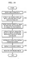
- Fig. 18 is a flowchart for explaining the operation of the electric filing apparatus according to the present embodiment. The operation according to the present embodiment will be described with reference to Figs. 17 and 18 hereinbelow.
- the application data reading function unit 1710 is constructed by a software module, etc. which is the so-called “Outside In Viewer Technology” produced by INSO Corporation, and inputs application data (*.doc) formed by application software (e.g., "Microsoft Word” produced by Microsoft Corporation) from the input device 1708 (such as the external storage device 106) and stores the inputted data into the memory (RAM 103) (step S51).
- application software e.g., "Microsoft Word” produced by Microsoft Corporation
- the software module cannot read all of the application data, but a filter corresponding to a desired application is previously optionally installed, thereby making it possible to read the application data corresponding thereto, displaying the application data, and outputting the character included in the application data.
- the application data character train extracting process function unit 1700 reads the characters in the application data from the memory (RAM 103), and converts the read character into a word. According to the present embodiment, when two or more spaces are successive, the spaces are replaced with one space. In the case where there is a carriage return line feed code, the code is also replaced with one space. Therefore, the output by the application data character train extracting process function unit 1700 is obtained by coupling a successive character train by using a space. In other words, the output is a set of character trains of the whole head page. The output is shown by 420 in Fig. 15 (step S50).
- the whole character train dividing process function unit 1701 uniformly divides the application data stored in the RAM 103 by a predetermined dividing number, thereby dividing the application data into a plurality of image blocks (step S52).
- Fig. 15 shows a diagram to uniformly divide into four blocks, a whole character train 420 having a proper amount which corresponds to the A4 size (1-page character information of the publication of the US. patent application) upon printing.
- the divided blocks are labeled as character train blocks A, B, C, and D (121 to 124). It is a purpose of this division to extract features from the four portions in the uniform arrangement on the whole character train.
- the partial character train extracting process function unit 1702 extracts a partial character train having a predetermined amount (only a predetermined character) from each character train block which is divided by the whole character train dividing process function unit 1701 (step S53). It is noted that the sequence after extraction has been described in the first embodiment, so that it is omitted herein, and the partial character trains extracted in step S54 are combined, the combined image is displayed in step S55, and the combined image is registered in step S56.
- Reference numeral 1602 in Fig. 16 denotes the reduced image obtained by the processes.
- the selection may be set automatically.
- the detail has been described in the second embodiment, and therefore the description is omitted.
- the present embodiment shows an example wherein although the reduced image combining process function unit 1703 converts the combined character train into the image and outputs the converted data as an image, a similar advantage is also obtained by outputting the combined character train to the display control function unit 1706 as a character as it is.
- the user instructs the display of the list of the reduced images from the input device 104.
- the CPU 101 sequentially reads out the reduced images stored in the external storage device 106, and displays the list on the display 105.
- a reduced image list window 701 is displayed on the display 105, and the list of the reduced images is displayed in the window.
- a divided position is displayed by a solid line 704 having a color different from that of the image so as to clearly identify the divided position.
- the display of the reduced image is not limited to the foregoing.
- the user instructs the selection of one reduced image from the reduced images which are displayed in the list by using the input device 104.
- the CPU 101 reads out the document image for the instructed reduced-image from the external storage device, sets a document image display window on the display 105, and displays the document image which is read out in the window.
- the present invention it is possible to form a reduced image capable of easily identifying the contents of even the document with a similar layout and the document with no distinctive feature in the display of the document list and search result list.
- the reduced image corresponds to the document comprising one page in the three embodiments
- the reduced image is generated for one selected page (such as a front page of a publication of a US. patent application) in the document comprising a plurality of pages and the generated reduced-image may correspond to the document comprising a plurality of pages.
- the selection can be automatically determined in accordance with the image information as a processing target. For example, it is discriminated whether or not the amount of black pixels is larger than a predetermined value for each partial image which is obtained by the division as shown in Fig. 8, and it is sufficient to adopt a partial image whose amount of black pixels is larger than the predetermined value.
- the electric filing apparatus has various component elements for realizing functions for searching and printing the information of the document stored in the file device 5, 1305, or 1705 shown in Fig. 2, 13, or 17, other than the foregoing, this description is omitted herein.
- the embodiment indicates an image shown in Fig. 6 or 9 as a reduced image, it is sufficient to have a function for displaying a normal reduced image in accordance with an instruction by the operator if he/she is interested in the layout of pages.
- the present invention may be applied to a system comprising a plurality of pieces of equipment (such as a host computer, interface equipment, a reader, and a printer), alternatively to an apparatus comprising single equipment (such as a copying machine and a facsimile apparatus).
- a system comprising a plurality of pieces of equipment (such as a host computer, interface equipment, a reader, and a printer)
- an apparatus comprising single equipment (such as a copying machine and a facsimile apparatus).
- the object of the present invention also can be attained by supplying to a system or an apparatus, a storage medium (or recording medium) which records a program code of software for implementing the functions of the embodiments, and by reading out and executing the program code stored in the storage medium by a computer (or CPU or MPU) in the system or apparatus.
- a storage medium or recording medium
- the functions of the aforementioned embodiments are implemented by the program code itself which is read out from the storage medium and the present invention comprises the storage medium which stores the program code.
- the present invention includes a case wherein the functions of the aforementioned embodiments can be effected not only by executing the program code which is read out by the computer, but also by executing a part or all of the actual processes by the OS (Operating System) which operates on the computer on the basis of the instruction of the program code.
- OS Operating System
- the present invention further includes a case wherein the functions of the aforementioned embodiments can be effected by writing the program code read-out from the storage medium into a memory provided for a function expansion card inserted to the computer or a function expansion unit connected to the computer, and by thereafter executing a part or all of the actual processes by a CPU, etc. provided for the function expansion card or function expansion unit on the basis of the instruction of the program code.
- the computer program can be obtained in electronic form for example by downloading the code over a network such as the internet.
- an electrical signal carrying processor implementable instructions for controlling a processor to carry out the method as hereinbefore described.
Abstract
Description
- The present invention relates to reduced image forming method and apparatus which are suitable for an electric filing apparatus for searching, displaying, and printing image data of a document stored with relation to predetermined managing information, etc.
- Recently, there has been published an electric filing apparatus for storing image data of a document formed by reading the document by a scanner, etc. with relation to document managing information and searching, displaying, printing the information, and the like. According to the electric filing apparatus, hitherto, in case of registering document managing information such as a document name, a number of pages, registered date, and a keyword, as and displaying a document list and a search result list, etc., the document managing information is displayed as information for identifying the document. However, it is difficult to identify the outline of the document by using only the document managing information. This situation results in further proposing an electric filing apparatus capable of forming and registering a reduced image of the document and displaying the reduced image in the document list and search result list.
- Fig. 10 is a diagram showing a functional construction example of a general electric filing apparatus for displaying a reduced image in a document list and a search result list. The electric filing apparatus has: a document
reading function unit 1000; a reduced image formingfunction unit 1001; a documentstoring function unit 1002; and a displaycontrol function unit 1003, as exemplified in Fig. 10. Among them, the documentreading function unit 1000 reads image data of a document by a scanner device, etc. (not shown). The reduced image formingfunction unit 1001 forms image data which is reduced with a proper size by thinning out a dot, etc. from the image data of the document read by the documentreading function unit 1000. The documentstoring function unit 1002 stores the image data of the document read by the documentreading function unit 1000 and the reduced image data of the document formed by the reduced image formingfunction unit 1001, with the relation therebetween. The displaycontrol function unit 1003 controls an operation for displaying the image data of the document and the reduced image which are stored in the documentstoring function unit 1002, for instance, displays a document list based on the reduced image shown in Fig. 11. - However, according to the conventional electric filing apparatus, in case of displaying the document list and the search result list, the outline of the document can be identified from the reduced image of the document, but only a layout of the whole document can be identified and a character written to the document cannot discriminated. This arises a problem that it is extremely difficult to identify a document having a similar layout and a document having no distinctive feature which has not large character and no figure from the reduced image. A preferable example is a reduced displaying example of a patent specification shown in Fig. 12.
- The example indicates the reduced image of 2 pages in a publication of a US. patent application, and it is impossible to discriminate what is written in both of the pages displayed in the right and left in the least.
- The present invention is devised in view of the aforementioned problems. It is an object of the present invention to form a reduced image capable of easily identifying the contents of even a document having a similar layout and a document having no distinctive feature in case of displaying a list of documents and a search result list.
- To accomplish the object, according to one construction of the present invention, there is provided a reduced image forming apparatus, comprising:
- extracting means for extracting a plurality of partial images from an original image;
- generating means for combining the plurality of partial images extracted by the extracting means and generating a combined image smaller than the original image; and
- indicating means for indicating the combined image generated by the generating means.
-
- To accomplish the object, according to another construction of the present invention, there is provided a reduced image forming apparatus, comprising:
- converting means for converting an original image into a character train;
- extracting means for extracting a partial character train from the character train converted by the converting means;
- generating means for combining a plurality of partial character trains extracted by the extracting means, converting the combined partial character trains into an image, and generating a combined image smaller than the original image; and
- indicating means for indicating the combined image generated by the generating means.
-
-
- Fig. 1 is a block diagram showing an outline of an apparatus construction of an electric filing apparatus according to the present embodiment;
- Fig. 2 is a block diagram showing a functional construction of the electric filing apparatus according to the present embodiment;
- Fig. 3 is a flowchart for explaining an operation of the electric filing apparatus according to the present embodiment;
- Fig. 4 is a conceptual diagram showing document image data;
- Fig. 5 is a diagram for explaining the division into a partial image and the extraction of the partial image according to the present invention;
- Fig. 6 is a diagram for explaining a state in which reduced images are combined by using the extracted partial image shown in Fig. 5;
- Fig. 7 is a diagram showing a display form of the reduced image according to the present embodiment;
- Fig. 8 is a diagram for explaining the division into the partial image and the extraction of the partial image according to a modified example;
- Fig. 9 is a diagram for explaining a state in which the reduced images are combined by using the extracted partial image shown in Fig. 8;
- Fig. 10 is a diagram showing a functional construction example of a general electric filing apparatus for displaying the reduced image in the document list and the search result list;
- Fig. 11 is a diagram showing an example to display the list of the documents on the basis of the reduced image in the general electric filing apparatus;
- Fig. 12 is a diagram showing an example to display the list of the documents on the basis of the reduced image in the general electric filing apparatus;
- Fig. 13 is a block diagram showing a functional construction of an electric filing apparatus according to a second embodiment;
- Fig. 14 is a flowchart for explaining an operation of the electric filing apparatus according to the second embodiment;
- Fig. 15 is a diagram for explaining the division into a partial character train and the extraction of the partial character train according to the second embodiment and a third embodiment;
- Fig. 16 is a diagram for explaining a state in which the reduced images are combined by using the extracted partial image or partial character train shown in Figs. 5 and 15;
- Fig. 17 is a block diagram showing a functional construction of an electric filing apparatus according to the third embodiment; and
- Fig. 18 is a flowchart for explaining an operation of the electric filing apparatus according to the third embodiment.
-
- Three embodiments will be described with reference to the accompanied drawings hereinbelow.
- Fig. 1 is a block diagram showing an outline of an apparatus construction of an electric filing apparatus according to the present embodiment.
Reference numeral 101 denotes a CPU which executes various control operations in the electric filing apparatus on the basis of the a control program stored in anROM 102 and anRAM 103; 102 the ROM which stores the control program executed by theCPU 101 and various data; and 103 the RAM which provides an area to store the control program executed by theCPU 101 and a work area of theCPU 101. -
Reference numeral 104 denotes an input device having a keyboard or pointing device; 105 a display which displays various images under the control operation by theCPU 101; 106 an external storage device which stores image data and a varieties of application programs; and 107 a scanner which reads an original image optically and converts the read image into digital data which is processable by theCPU 101. - Fig. 2 is a block diagram showing a functional construction of the electric filing apparatus according to the present embodiment. Referring to Fig. 2,
reference numeral 1 denotes an image dividing process function unit; 2 a partial image extracting process function unit; 3 a reduced image combining process function unit; 4 a document registering function unit; 5 a filing device; 6 a display control function unit; 7 a selecting function unit; 8 an input device; 9 an output device; and 10 a document reading function unit. Note that theCPU 101 executes the control program which is loaded in theRAM 103 from theexternal storage device 106 and controls thescanner 107 andexternal storage device 106, thereby realizing the function units. - Fig. 3 is a flowchart for explaining the operation of the electric filing apparatus according to the present embodiment. The operation of the present embodiment will be described with reference to Figs. 2 and 3 hereinbelow.
- To start with, the document
reading function unit 10 inputs document image data as a processing target from the input device 8 (such as thescanner 107 and external storage device 106) and stores the data into the memory (RAM 103) (step S11). The document image data may be data of a 400dpi-resolution which is read by thescanner 107 in real time or may be data which is previously read and stored in theexternal storage device 106. - The image dividing
process function unit 1 uniformly divides the document image data stored in theRAM 103 by a predetermined dividing number, thereby dividing the document image data into a plurality of image blocks (step S12). - According to the present embodiment, an image 20 (one page of a publication of a US. patent application) of an A4 size is uniformly divided into four blocks, as shown in Fig. 4. Fig. 4 is a conceptual diagram showing the document image data stored in the
RAM 103. The divided blocks are labeled as image blocks A, B, C, and D (21 to 24). It is a purpose of this division to extract features from the four portions in the uniform arrangement on the image. - The partial image extracting
process function unit 2 extracts a partial image having a predetermined amount (a predetermined size) from each image block which is divided by the image dividing process function unit 1(step S13). It is noted that the extracting amount is determined dependently upon a rate of the size of the reduced image on thedisplay 105 and the size of the original image on paper. - Normally, a plurality of reduced images are displayed in a reduced image list. If assuming that the size of an image is equal to about 5 cm, for example, on a 17inch-display, it is possible to display eight reduced images.
- An image corresponding to the A4 size has a width of about 20 cm, so that the reduction ratio is set to 1/4 one-dimensionally. That is, the reduction ratio is equal to 1/16 on the area. Accordingly, if extracting only an area of 1/16 from each image block shown in Fig. 4, the sum of width of four image blocks is equal to about 5 cm on the display.
- Therefore, according to the present embodiment, each image block is uniformly divided into sixteen partial images, as shown in Fig. 5, and the partial image is extracted from the image blocks one by one. According to the present invention, the selecting
function unit 7 is set to select the head partial image in each image block. Four partial images (501 to 504) as shown by hatched portions in Fig. 5 are extracted. - The reduced image combining
process function unit 3 vertically aligns the partial images extracted by the partial image extractingprocess function unit 2, thereby constructing one reduced image, as shown in Fig. 6, and stores the reduced image into the memory (RAM 103) (step S14). In other words, the constructed reduced image is composed of an extractedpartial image 601 of an image block A21, an extractedpartial image 602 of an image block B22, an extractedpartial image 603 of an image block C23, and an extractedpartial image 604 of an image block D24, in the descending order. Further, the thus-combined image is reduced within a range in capable of discriminating a character. - Since the resolution of a CRT is normally equal to about 100dpi, the size capable of recognizing one character on the CRT is limited to about 2 mm every character width. The original used in the present embodiment is a publication of a US. patent application, and the size of one character is about 2mm on the paper. Because the image in this example is scanned by the
scanner 107 having the 400dpi-resolution, the image is reduced to 1/4. The reduced image is displayed on awindow 701 on a screen of thedisplay 105 as reduced images (702, 703) via the displaycontrol function unit 6, as shown in Fig. 7. Incidentally, Fig. 7 shows to display the reduced image obtained by the processes. - The document registering
function unit 4 registers the document image data read by the documentreading function unit 10 and the reduced image processed by the reduced image combiningprocess function unit 3 into thefile device 5 with relationship therebetween (step S16). Thefile device 5 stores the document image data and document managing information such as a keyword with a relation therebetween as a database. The displaycontrol function unit 6 controls an operation to display the image data in a character area stored in thefile device 5 to the output device 9 (such as the display 105). Incidentally, although the CRT is used as a display in the present embodiment, not only the CRT but also an LCD may be used if using them as a display. - As mentioned above, according to the present embodiment, the image extracted from a plurality of areas in one page is reduced and indicated within a decidable range, so that the operator can discriminate the contents of the indicated document easily. That is, even with respect to a document having a similar layout or a document with no distinctive feature, so long as the reduced image is used, the character can be recognized throughout the document, though a part of the document is one part. Therefore, it is able to identify the document easily.
- Normally, a document has a margin and the publication of the US. patent application is set to have a margin of about 1/16 vertically. On the contrary, the selecting
function unit 7 shown in the embodiment is set to uniquely select the head portion of each image block. A space portion is extracted in portions of the image blocks A21 and C23 as a result of the combination of the reduced images, as shown by 601 and 603 in Fig. 6. The quantity of information is decreased and the advantage is decreased to the half (no feature is extracted from the portions of the image blocks A21 and C23). - Setting values of the selecting
function unit 7 may be set to extract the partial images which are located at the second order from the head in the image blocks A21 and C23, and to extract the head partial images from the image blocks B22 and D24. When setting the foregoing, hatchedportions 801 to 804 shown in Fig. 8 become an extraction target. Consequently, with regard to a combined reduced-image as shown in Fig. 9, thepartial image 801 in Fig. 8 becomes an extractedpartial image 901; thepartial image 802 in Fig. 8 an extractedpartial image 902; thepartial image 803 in Fig. 8 an extractedpartial image 903; and thepartial image 804 in Fig. 8 an extractedpartial image 904. As compared with those in Fig. 6, the quantity of information can be increased. - A second embodiment according to the present invention will be described in detail with reference to the accompanied drawings hereinbelow.
- The outline of an apparatus construction is as same as that of Fig. 1 which has been described in the first embodiment.
- Fig. 13 is a block diagram showing a functional construction of an electric filing apparatus according to the present embodiment. Referring to Fig. 13,
reference numeral 1300 denotes a character recognizing process function unit; 1301 a whole character train dividing process function unit; 1302 a partial character train extracting process function unit; 1303 a reduced image combining process function unit; 1304 a document registering function unit; 1305 a file device; 1306 a display control function unit; 1307 a selecting function unit; 1308 an input device; 1309 an output device; and 1310 a document reading function unit. Incidentally, theCPU 101 executes the control program loaded in theRAM 103 from theexternal storage device 106 and controls thescanner 107 and theexternal storage device 106, etc., thereby realizing the function units. - Fig. 14 is a flowchart for explaining the operation of the electric filing apparatus according to the present embodiment. The operation according to the present embodiment will be described with reference to Figs. 13 and 14 hereinbelow.
- First of all, the document
reading function unit 1310 inputs document image data as a processing target from the input device 1308 (such as thescanner 107 and external storage device 106) and stores the image data into the memory (RAM 103) (step S41). The document image data may be data of a 400dpi-resolution which is read by thescanner 107 in real time or may be data which is previously read and stored in theexternal storage device 106. The character recognizingprocess function unit 1300 reads an image from the memory (RAM 103) and outputs the recognized character. According to the present embodiment, in case of two or more spaces are successive, the character recognizingprocess function unit 1300 outputs only one space and outputs only one space in case of a carriage return line feed control code. The output by the character recognizing process function unit is obtained by coupling a character train as a set of sequent characters including no space by using a space. In other words, the output is a character train of the whole one page (step S40). - The image
processing function unit 1301 uniformly divides the character train stored in theRAM 103 by a predetermined dividing number, thereby dividing the character train into a plurality of character train blocks (step S42). - According to the present embodiment, an image of the A4 size (1-page character information of the publication of the US. patent application) is divided into four blocks uniformly, as shown in Fig. 15. Fig. 15 is a diagram for explaining the division of the partial character train stored in the
RAM 103 and the extraction of the partial character train. The divided blocks are labeled as character train blocks A, B, C, and D (21 to 24). It is a purpose of this division to extract features from the four portions in the uniform arrangement on the image. The partial character train extractingprocess function unit 1302 extracts a partial character train having a predetermined amount (a predetermined size) from each character train block which is divided by the character train dividing process function unit 1301 (step S43). - It is noted that the sequence after extraction has been described in the first embodiment, so that it is omitted herein. The partial character trains extracted in step S44 are combined, the combined image is displayed in step S45, and the combined image is registered in step S46.
-
Reference numeral 1602 in Fig. 16 denotes the reduced image obtained by the processes. - Incidentally, it is premised that to manually set the selection from among the extracted partial character trains by the selecting
function unit 1307 in the foregoing. According to the present embodiment, the following conditions are fixed, namely, whether or not one is selected if there are two or more font kinds, font sizes, character intervals, or spaces; whether or not a carriage return line feed; CRLF) code is removed; whether a spacing of the English word lap is ON/OFF; and the like. However, it is possible fully to select whether each setting by the selectingfunction unit 1307 is fixed or unfixed. If the setting is fixed, of course, each arbitrary setting can be performed manually. If the setting is unfixed, it is able to decide the setting automatically in accordance with the image information as a processing target. For instance, a standard character size on an OS is picked up and the best number of characters is automatically determined. On the other hand, it is possible fully to designate the number of characters and adjust the font size. If deciding the dividing number of character train blocks or the character number of the partial character train manually and arbitrarily, this case is included in the range of the present invention. - It is possible to select the position of the partial character train used for the reduced image, so that the document information is obtained advantageously.
- As mentioned above, according to the present embodiment, the whole character train in the one page is combined with the partial character train extracted from a plurality of areas, thereby forming the reduced image, and thus the character is displayed within the decidable range, and the operator can discriminate the document contents indicated easily. That is, even with respect to the document with a similar layout and the document having no distinctive feature, the characters in the whole reduced image can be recognized, though the document is one part, using only the reduced image. As a result, the document can be identified easily.
- Further, it is able to avoid a margin and a space by a carriage return line feed, etc. shown by 1601 in Fig. 16, as shown by 1602 in Fig. 16. It is possible to provide a reduced image having a large amount of information.
- A third preferred embodiment according to the present invention will be described in detail with reference to the accompanied drawings hereinbelow.
- The outline of an apparatus construction is as same as that of Fig. 1 which has been described in the first embodiment.
- Fig. 17 is a block diagram showing a functional construction of an electric filing apparatus according to the present embodiment. Referring to Fig. 17,
reference numeral 1700 denotes an application data character train extracting process function unit; 1701 a whole character train dividing process function unit; 1702 a partial character train extracting process function unit; 1703 a reduced image combining process function unit; 1704 a document registering function unit; 1705 a file device; 1706 a display control function unit; 1707 a selecting function unit; 1708 an input device; 1709 an output device; and 1710 an application data reading function unit. Incidentally, theCPU 101 executes the control program loaded in theRAM 103 from theexternal storage device 106 and controls theexternal storage device 106, thereby realizing the function units. - Fig. 18 is a flowchart for explaining the operation of the electric filing apparatus according to the present embodiment. The operation according to the present embodiment will be described with reference to Figs. 17 and 18 hereinbelow.
- First of all, the application data reading
function unit 1710 is constructed by a software module, etc. which is the so-called "Outside In Viewer Technology" produced by INSO Corporation, and inputs application data (*.doc) formed by application software (e.g., "Microsoft Word" produced by Microsoft Corporation) from the input device 1708 (such as the external storage device 106) and stores the inputted data into the memory (RAM 103) (step S51). Note that the software module cannot read all of the application data, but a filter corresponding to a desired application is previously optionally installed, thereby making it possible to read the application data corresponding thereto, displaying the application data, and outputting the character included in the application data. - The application data character train extracting
process function unit 1700 reads the characters in the application data from the memory (RAM 103), and converts the read character into a word. According to the present embodiment, when two or more spaces are successive, the spaces are replaced with one space. In the case where there is a carriage return line feed code, the code is also replaced with one space. Therefore, the output by the application data character train extractingprocess function unit 1700 is obtained by coupling a successive character train by using a space. In other words, the output is a set of character trains of the whole head page. The output is shown by 420 in Fig. 15 (step S50). - The whole character train dividing
process function unit 1701 uniformly divides the application data stored in theRAM 103 by a predetermined dividing number, thereby dividing the application data into a plurality of image blocks (step S52). - According to the present embodiment, Fig. 15 shows a diagram to uniformly divide into four blocks, a
whole character train 420 having a proper amount which corresponds to the A4 size (1-page character information of the publication of the US. patent application) upon printing. The divided blocks are labeled as character train blocks A, B, C, and D (121 to 124). It is a purpose of this division to extract features from the four portions in the uniform arrangement on the whole character train. - The partial character train extracting
process function unit 1702 extracts a partial character train having a predetermined amount (only a predetermined character) from each character train block which is divided by the whole character train dividing process function unit 1701 (step S53). It is noted that the sequence after extraction has been described in the first embodiment, so that it is omitted herein, and the partial character trains extracted in step S54 are combined, the combined image is displayed in step S55, and the combined image is registered in step S56. -
Reference numeral 1602 in Fig. 16 denotes the reduced image obtained by the processes. - Incidentally, although it is premised to manually set the selection of the extracted partial image by the selecting
function unit 1707 in the foregoing, the selection may be set automatically. The detail has been described in the second embodiment, and therefore the description is omitted. - The present embodiment shows an example wherein although the reduced image combining
process function unit 1703 converts the combined character train into the image and outputs the converted data as an image, a similar advantage is also obtained by outputting the combined character train to the displaycontrol function unit 1706 as a character as it is. - Herein, an example for selecting and displaying the document image will be described simply by using the thus-registered document image data and reduced image.
- First, in order to select the document image, the user instructs the display of the list of the reduced images from the
input device 104. Under the instruction, theCPU 101 sequentially reads out the reduced images stored in theexternal storage device 106, and displays the list on thedisplay 105. As shown in Fig. 7, a reducedimage list window 701 is displayed on thedisplay 105, and the list of the reduced images is displayed in the window. With regard to the reduced image displayed in thewindow 701, a divided position is displayed by asolid line 704 having a color different from that of the image so as to clearly identify the divided position. However, if it is unnecessary that the solid line is clearly identified, the display of the reduced image is not limited to the foregoing. - The user instructs the selection of one reduced image from the reduced images which are displayed in the list by using the
input device 104. Under the instruction, theCPU 101 reads out the document image for the instructed reduced-image from the external storage device, sets a document image display window on thedisplay 105, and displays the document image which is read out in the window. - According to the three embodiments, it is able to easily understand that the foregoing is the contents regarding the reduced-image formation which is preferable to an electric filing apparatus for searching, displaying, and printing image data of a document stored with relation to predetermined managing information as exemplified in Figs. 6 and 9.
- According to the present invention, it is possible to form a reduced image capable of easily identifying the contents of even the document with a similar layout and the document with no distinctive feature in the display of the document list and search result list.
- Although one reduced image corresponds to the document comprising one page in the three embodiments, the reduced image is generated for one selected page (such as a front page of a publication of a US. patent application) in the document comprising a plurality of pages and the generated reduced-image may correspond to the document comprising a plurality of pages.
- Although it is premised to manually set the selection from among the extracted partial images by the selecting
function unit 7 in Fig. 2, the selectingfunction unit 1307 in Fig. 13, and the selectingfunction unit 1707 in Fig. 17, the selection can be automatically determined in accordance with the image information as a processing target. For example, it is discriminated whether or not the amount of black pixels is larger than a predetermined value for each partial image which is obtained by the division as shown in Fig. 8, and it is sufficient to adopt a partial image whose amount of black pixels is larger than the predetermined value. - It is noted that although the electric filing apparatus according to the present embodiment has various component elements for realizing functions for searching and printing the information of the document stored in the
file device - Although the embodiment indicates an image shown in Fig. 6 or 9 as a reduced image, it is sufficient to have a function for displaying a normal reduced image in accordance with an instruction by the operator if he/she is interested in the layout of pages.
- The present invention may be applied to a system comprising a plurality of pieces of equipment (such as a host computer, interface equipment, a reader, and a printer), alternatively to an apparatus comprising single equipment (such as a copying machine and a facsimile apparatus).
- Obviously, the object of the present invention also can be attained by supplying to a system or an apparatus, a storage medium (or recording medium) which records a program code of software for implementing the functions of the embodiments, and by reading out and executing the program code stored in the storage medium by a computer (or CPU or MPU) in the system or apparatus. In this case, the functions of the aforementioned embodiments are implemented by the program code itself which is read out from the storage medium and the present invention comprises the storage medium which stores the program code. Obviously, the present invention includes a case wherein the functions of the aforementioned embodiments can be effected not only by executing the program code which is read out by the computer, but also by executing a part or all of the actual processes by the OS (Operating System) which operates on the computer on the basis of the instruction of the program code.
- Obviously, the present invention further includes a case wherein the functions of the aforementioned embodiments can be effected by writing the program code read-out from the storage medium into a memory provided for a function expansion card inserted to the computer or a function expansion unit connected to the computer, and by thereafter executing a part or all of the actual processes by a CPU, etc. provided for the function expansion card or function expansion unit on the basis of the instruction of the program code.
- Further, the computer program can be obtained in electronic form for example by downloading the code over a network such as the internet. Thus in accordance with another aspect of the present invention there is provided an electrical signal carrying processor implementable instructions for controlling a processor to carry out the method as hereinbefore described.
Claims (55)
- A reduced image forming apparatus comprising:extracting means for extracting a plurality of partial images from an original image;generating means for combining the plurality of partial images extracted by said extracting means and generating a combined image smaller than said original image; andindicating means for indicating the combined image generated by said generating means.
- An apparatus according to claim 1, wherein said extracting means has:dividing means for dividing said original image into a plurality of image blocks; andobtaining means for obtaining the partial image from each of said plurality of image blocks.
- An apparatus according to claim 2, wherein said dividing means divides said original image into a plurality of uniform image blocks.
- An apparatus according to claim 2, wherein said obtaining means divides said image block into a plurality of partial images, and obtains the partial image at a same position in each image block.
- An apparatus according to claim 2, wherein said obtaining means divides said image block into a plurality of uniform partial images, and obtains the partial image at a position set for each image block.
- An apparatus according to claim 1, wherein said generating means decreases an image resolution within a range in which a character can be visually recognized as a character on said indicating means, and generates a combined image smaller than said original image.
- An apparatus according to claim 1, wherein said extracting means further has application data extracting means for reading application data and extracting said application data.
- An apparatus according to claim 7, wherein said application data is data which is formed in an application.
- A reduced image forming method comprising:an extracting step of extracting a plurality of partial images from an original image;a generating step of combining the plurality of partial images extracted by said extracting step and generating a combined image smaller than said original image; andan indicating step of indicating the combined image generated by said generating step.
- A method according to claim 9, wherein said extracting step has:a dividing step of dividing said original image into a plurality of image blocks; andan obtaining step of obtaining the partial image from each of said plurality of image blocks.
- A method according to claim 10, wherein said dividing step divides said original image into a plurality of uniform image blocks.
- A method according to claim 10, wherein said obtaining step divides said image block into a plurality of partial images, and obtains the partial image at a same position in each image block.
- A method according to claim 10, wherein said obtaining step divides said image block into a plurality of uniform partial images, and obtains the partial image at a position set for each image block.
- A method according to claim 9, wherein said generating step decreases an image resolution within a range in which a character can be visually recognized as a character on said indicating step, and generates a combined image smaller than said original image.
- A method according to claim 9, wherein said extracting step further has application data extracting step of reading application data and extracting said application data.
- A method according to claim 15, wherein said application data is data which is formed in an application.
- A storage medium storing a control program for making a computer form a reduced image based on an original image, wherein said control program comprises the codes for:an extracting step of extracting a plurality of partial images from an original image;a generating step of combining the plurality of partial images extracted by said extracting step and generating a combined image smaller than said original image; andan indicating step of indicating the generated combined image generated by said generating step.
- A medium according to claim 17, wherein said extracting step has the codes for:a dividing step of dividing said original image into a plurality of image blocks; andan obtaining step of obtaining the partial image from each of said plurality of image blocks.
- A medium according to claim 18, wherein said dividing step divides said original image into a plurality of uniform image blocks.
- A medium according to claim 18, wherein said obtaining step divides said image block into a plurality of partial images, and obtains the partial image at a same position in each image block.
- A medium according to claim 18, wherein said obtaining step divides said image block into a plurality of uniform partial images, and obtains the partial image at a position set for each image block.
- A medium according to claim 17, wherein said generating step decreases an image resolution within a range in which a character can be visually recognized as a character on said indicating step, and generates a combined image smaller than said original image.
- A medium according to claim 17, wherein said extracting step further has application data extracting step of reading application data and extracting said application data.
- A medium according to claim 23, wherein said application data is data which is formed in an application.
- A reduced image forming apparatus comprising:converting means for converting an original image into a character train;extracting means for extracting a partial character train from the character train converted by said converting means;generating means for combining a plurality of partial character trains extracted by said extracting means, converting the combined partial character trains into an image, and generating a combined image smaller than said original image; andindicating means for indicating the combined image generated by said generating means.
- An apparatus according to claim 25, wherein said converting means has:character train recognizing means for recognizing a character train; andreplacing means for replacing a two or more sequent spaces recognized by said recognizing means or a carriage return line feed control code and a plurality of spaces subsequent thereto with one space.
- An apparatus according to claim 25, wherein said extracting means has:dividing means for dividing the character train replaced by said replacing means into a plurality of character train blocks; andobtaining means for obtaining the partial character train from each of said plurality of character train blocks.
- An apparatus according to claim 27, wherein said dividing means divides the character train replaced by said replacing means into a plurality of uniform character train blocks.
- An apparatus according to claim 27, wherein said obtaining means divides said character train block into a plurality of partial character trains, and obtains the partial character train at a same position in each character train block.
- An apparatus according to claim 27, wherein said obtaining means divides said character train block into a plurality of uniform partial character trains, and obtains the partial character train at a position set for each character train block.
- An apparatus according to claim 25, wherein said generating means decreases an image resolution within a range in which a character can be visually recognized as a character on said indicating means, and generates a combined image smaller than said original image.
- An apparatus according to claim 25, wherein said extracting means further has application data extracting means for reading application data and extracting the character train included in said application data.
- An apparatus according to claim 32, wherein said application data is data which is formed in an application.
- A reduced image forming method comprising:a converting step of converting an original image into a character train;an extracting step of extracting a partial character train from the character train converted by said converting step;a generating step of combining a plurality of partial character trains extracted by said extracting step, converting the combined partial character trains into an image, and generating a combined image smaller than said original image; andan indicating step of indicating the combined image generated by said generating step.
- A method according to claim 34, wherein said converting step has:a character train recognizing step of recognizing a character train; anda replacing step of replacing a two or more sequent spaces recognized by said recognizing step or a carriage return line feed control code and a plurality of spaces subsequent thereto with one space.
- A method according to claim 34, wherein said extracting step has:a dividing step of dividing the character train replaced by said replacing step into a plurality of character train blocks; andan obtaining step of obtaining the partial character train from each of said plurality of character train blocks.
- A method according to claim 36, wherein said dividing step divides the character train replaced by said replacing step into a plurality of uniform character train blocks.
- A method according to claim 36, wherein said obtaining step divides said character train block into a plurality of partial character trains, and obtains the partial character train at a same position in each character train block.
- A method according to claim 36, wherein said obtaining step divides said character train block into a plurality of uniform partial character trains, and obtains the partial character train at a position set for each character train block.
- A method according to claim 34, wherein said generating step decreases an image resolution within a range in which a character can be visually recognized as a character on said indicating step, and generates a combined image smaller than said original image.
- A method according to claim 34, wherein said extracting step further has application data extracting step of reading application data and extracting the character train included in said application data.
- A method according to claim 41, wherein said application data is data which is formed in an application.
- A storage medium comprising the codes for:a converting step of converting an original image into a character train;an extracting step of extracting a partial character train from the character train converted by said converting step;a generating step of combining a plurality of partial character trains extracted by said extracting step, converting the combined partial character trains into an image, and generating a combined image smaller than said original image; andan indicating step of indicating the combined image generated by said generating step.
- A medium according to claim 43, wherein said converting step has a character train recognizing step of recognizing a character train.
- A medium according to claim 43, wherein converting step has a code for a replacing step of replacing a two or more sequent spaces recognized by said recognizing step or a carriage return line feed control code and a plurality of spaces subsequent thereto with one space.
- A medium according to claim 43, wherein said extracting step has the codes for:a dividing step of dividing the character train replaced by said replacing step into a plurality of character train blocks; andan obtaining step of obtaining the partial character train from each of said plurality of character train blocks.
- A medium according to claim 46, wherein said dividing step divides the character train replaced by said replacing step into a plurality of uniform character train blocks.
- A medium according to claim 46, wherein said obtaining step divides said character train block into a plurality of partial character trains, and obtains the partial character train at a same position in each character train block.
- A medium according to claim 46, wherein said obtaining step divides said character train block into a plurality of uniform partial character trains, and obtains the partial character train at a position set for each character train block.
- A medium according to claim 43, wherein said generating step decreases an image resolution within a range in which a character can be visually recognized as a character on said indicating step, and generates a combined image smaller thar said original image.
- A medium according to claim 43, wherein said extracting step further has application data extracting step of reading application data and extracting the character train included in said application data.
- A medium according to claim 51, wherein said application data is data which is formed in an application.
- A method of image processing for use in an image system in which a reduced image is extracted from the image for display during search or retrieval, the reduced image being extracted by selecting a portion of the image and storing data representative of the portion at a resolution sufficient to facilitate recognition of the portion when displayed.
- A computer program comprising processor implementable instructions for carrying out a method as claimed in any one of claims 9 to 16, 34 to 42 and 53.
- An electrical signal carrying processor implementable instructions for controlling a processor to carry out the method of any one of claims 9 to 16, 34 to 42 and 53.
Applications Claiming Priority (4)
| Application Number | Priority Date | Filing Date | Title |
|---|---|---|---|
| JP17157699 | 1999-06-17 | ||
| JP17157699 | 1999-06-17 | ||
| JP2000135780 | 2000-05-09 | ||
| JP2000135780A JP4310023B2 (en) | 1999-06-17 | 2000-05-09 | Reduced image creation method and apparatus, and storage medium |
Publications (3)
| Publication Number | Publication Date |
|---|---|
| EP1061460A2 true EP1061460A2 (en) | 2000-12-20 |
| EP1061460A3 EP1061460A3 (en) | 2003-04-23 |
| EP1061460B1 EP1061460B1 (en) | 2013-08-14 |
Family
ID=26494264
Family Applications (1)
| Application Number | Title | Priority Date | Filing Date |
|---|---|---|---|
| EP00305100.0A Expired - Lifetime EP1061460B1 (en) | 1999-06-17 | 2000-06-16 | Partial image forming method and apparatus for filing documents |
Country Status (3)
| Country | Link |
|---|---|
| US (1) | US6996293B1 (en) |
| EP (1) | EP1061460B1 (en) |
| JP (1) | JP4310023B2 (en) |
Families Citing this family (8)
| Publication number | Priority date | Publication date | Assignee | Title |
|---|---|---|---|---|
| JP2008252289A (en) | 2007-03-29 | 2008-10-16 | Brother Ind Ltd | Image forming system, data processing apparatus, program and image forming apparatus |
| JP5152031B2 (en) * | 2008-03-24 | 2013-02-27 | ブラザー工業株式会社 | Image processing apparatus and computer program |
| JP5736638B2 (en) * | 2008-10-20 | 2015-06-17 | 株式会社リコー | Image processing device |
| JP2011070601A (en) * | 2009-09-28 | 2011-04-07 | Fujitsu Ltd | Device, and method for managing image, and computer program |
| JP5594269B2 (en) | 2011-09-29 | 2014-09-24 | コニカミノルタ株式会社 | File name creation device, image forming device, and file name creation program |
| US8773733B2 (en) * | 2012-05-23 | 2014-07-08 | Eastman Kodak Company | Image capture device for extracting textual information |
| JP2013085276A (en) * | 2012-12-11 | 2013-05-09 | Pfu Ltd | Image processing device and image processing method |
| JP6609955B2 (en) * | 2015-03-27 | 2019-11-27 | 日本電気株式会社 | Image processing apparatus, image processing method, and program |
Citations (3)
| Publication number | Priority date | Publication date | Assignee | Title |
|---|---|---|---|---|
| US4808987A (en) * | 1983-12-21 | 1989-02-28 | Hitachi, Ltd. | Image data file storage and retrieval system for an image data filing system |
| US5682441A (en) * | 1995-11-08 | 1997-10-28 | Storm Technology, Inc. | Method and format for storing and selectively retrieving image data |
| US5717940A (en) * | 1995-04-28 | 1998-02-10 | Ricoh Company, Ltd. | Method of selecting a target document using features of an example page |
Family Cites Families (18)
| Publication number | Priority date | Publication date | Assignee | Title |
|---|---|---|---|---|
| GB2030823B (en) * | 1978-10-02 | 1982-11-03 | Ibm | Image data manipulation apparatus |
| JPH063608B2 (en) * | 1984-06-30 | 1994-01-12 | 株式会社東芝 | Document image editing device |
| US4850026A (en) * | 1987-10-13 | 1989-07-18 | Telecommunications Laboratories Dir. Gen'l Of Telecom. Ministry Of Communications | Chinese multifont recognition system based on accumulable stroke features |
| EP0385009A1 (en) * | 1989-03-03 | 1990-09-05 | Hewlett-Packard Limited | Apparatus and method for use in image processing |
| JP2722803B2 (en) * | 1990-10-01 | 1998-03-09 | 松下電器産業株式会社 | Document creation device |
| GB9103080D0 (en) * | 1991-02-14 | 1991-04-03 | British And Foreign Bible The | Analysing textual documents |
| JP2579397B2 (en) * | 1991-12-18 | 1997-02-05 | インターナショナル・ビジネス・マシーンズ・コーポレイション | Method and apparatus for creating layout model of document image |
| JP3253356B2 (en) * | 1992-07-06 | 2002-02-04 | 株式会社リコー | Document image area identification method |
| JP3338107B2 (en) * | 1993-02-22 | 2002-10-28 | 富士写真フイルム株式会社 | Image processing device for micro film reader |
| US5424853A (en) * | 1993-04-19 | 1995-06-13 | Sharp Kabushiki Kaisha | Image processing apparatus |
| JP3443146B2 (en) * | 1993-11-15 | 2003-09-02 | 株式会社リコー | Image combining method and image recording device |
| US5517587A (en) * | 1994-09-23 | 1996-05-14 | International Business Machines Corporation | Positioning method and apparatus for line scanned images |
| JPH08214201A (en) * | 1994-11-28 | 1996-08-20 | Canon Inc | Image pickup device |
| JP3504054B2 (en) * | 1995-07-17 | 2004-03-08 | 株式会社東芝 | Document processing apparatus and document processing method |
| US6167410A (en) * | 1997-01-30 | 2000-12-26 | Casio Computer Co., Ltd. | Document processing apparatus for adding predetermined design types to an original document |
| SG71018A1 (en) * | 1997-03-01 | 2000-03-21 | Inst Of Systems Science Nat Un | Robust identification code recognition system |
| US6356314B1 (en) * | 1997-03-10 | 2002-03-12 | Komatsu Ltd. | Image synthesizing device and image conversion device for synthesizing and displaying an NTSC or other interlaced image in any region of a VCA or other non-interlaced image |
| US6301386B1 (en) * | 1998-12-09 | 2001-10-09 | Ncr Corporation | Methods and apparatus for gray image based text identification |
-
2000
- 2000-05-09 JP JP2000135780A patent/JP4310023B2/en not_active Expired - Fee Related
- 2000-06-14 US US09/593,775 patent/US6996293B1/en not_active Expired - Fee Related
- 2000-06-16 EP EP00305100.0A patent/EP1061460B1/en not_active Expired - Lifetime
Patent Citations (3)
| Publication number | Priority date | Publication date | Assignee | Title |
|---|---|---|---|---|
| US4808987A (en) * | 1983-12-21 | 1989-02-28 | Hitachi, Ltd. | Image data file storage and retrieval system for an image data filing system |
| US5717940A (en) * | 1995-04-28 | 1998-02-10 | Ricoh Company, Ltd. | Method of selecting a target document using features of an example page |
| US5682441A (en) * | 1995-11-08 | 1997-10-28 | Storm Technology, Inc. | Method and format for storing and selectively retrieving image data |
Also Published As
| Publication number | Publication date |
|---|---|
| JP4310023B2 (en) | 2009-08-05 |
| JP2001061060A (en) | 2001-03-06 |
| US6996293B1 (en) | 2006-02-07 |
| EP1061460B1 (en) | 2013-08-14 |
| EP1061460A3 (en) | 2003-04-23 |
Similar Documents
| Publication | Publication Date | Title |
|---|---|---|
| EP1480440B1 (en) | Image processing apparatus, control method therefor, and program | |
| US8726178B2 (en) | Device, method, and computer program product for information retrieval | |
| US7272269B2 (en) | Image processing apparatus and method therefor | |
| CN101178725B (en) | Device and method for information retrieval | |
| EP2333655A2 (en) | Printed matter examination apparatus, a printed matter examination method, a storage medium, and a printed matter examination system | |
| JP4533273B2 (en) | Image processing apparatus, image processing method, and program | |
| JP4502385B2 (en) | Image processing apparatus and control method thereof | |
| US7679777B2 (en) | Job supplement for electronic printing machines | |
| US8144988B2 (en) | Document-image-data providing system, document-image-data providing device, information processing device, document-image-data providing method, information processing method, document-image-data providing program, and information processing program | |
| JP2002171400A (en) | Image processor | |
| US8818110B2 (en) | Image processing apparatus that groups object images based on object attribute, and method for controlling the same | |
| US7844080B2 (en) | Image processing system and image processing method, and computer program | |
| EP1061460B1 (en) | Partial image forming method and apparatus for filing documents | |
| US20070257922A1 (en) | Removable media device and image displaying system | |
| US8582148B2 (en) | Image processing apparatus and image processing method | |
| JP2006093917A (en) | Image reading apparatus and image processor, and image forming apparatus | |
| US8194982B2 (en) | Document-image-data providing system, document-image-data providing device, information processing device, document-image-data providing method, information processing method, document-image-data providing program, and information processing program | |
| JP2007041709A (en) | Document processing system, control method of document processing system, document processing device, computer program and computer readable storage medium | |
| JP4179977B2 (en) | Stamp processing apparatus, electronic approval system, program, and recording medium | |
| JP2006333248A (en) | Image processing apparatus, image processing method, program and storage medium | |
| JP2005149323A (en) | Image processing system, image processing apparatus, and image processing method | |
| US20110157658A1 (en) | Imaging processing apparatus, method for controlling the same, and program | |
| JP7314627B2 (en) | CONTROL DEVICE, IMAGE FORMING APPARATUS, CONTROL METHOD AND CONTROL PROGRAM | |
| US20230244889A1 (en) | Information processing apparatus, non-transitory computer readable medium storing information processing program, and information processing method | |
| JP2010092141A (en) | Image processing system, image reader, image processor, and image processing program |
Legal Events
| Date | Code | Title | Description |
|---|---|---|---|
| PUAI | Public reference made under article 153(3) epc to a published international application that has entered the european phase |
Free format text: ORIGINAL CODE: 0009012 |
|
| AK | Designated contracting states |
Kind code of ref document: A2 Designated state(s): AT BE CH CY DE DK ES FI FR GB GR IE IT LI LU MC NL PT SE |
|
| AX | Request for extension of the european patent |
Free format text: AL;LT;LV;MK;RO;SI |
|
| PUAL | Search report despatched |
Free format text: ORIGINAL CODE: 0009013 |
|
| AK | Designated contracting states |
Designated state(s): AT BE CH CY DE DK ES FI FR GB GR IE IT LI LU MC NL PT SE |
|
| AX | Request for extension of the european patent |
Extension state: AL LT LV MK RO SI |
|
| 17P | Request for examination filed |
Effective date: 20030919 |
|
| 17Q | First examination report despatched |
Effective date: 20031121 |
|
| AKX | Designation fees paid |
Designated state(s): DE FR GB |
|
| GRAP | Despatch of communication of intention to grant a patent |
Free format text: ORIGINAL CODE: EPIDOSNIGR1 |
|
| GRAP | Despatch of communication of intention to grant a patent |
Free format text: ORIGINAL CODE: EPIDOSNIGR1 |
|
| INTG | Intention to grant announced |
Effective date: 20130326 |
|
| GRAS | Grant fee paid |
Free format text: ORIGINAL CODE: EPIDOSNIGR3 |
|
| GRAA | (expected) grant |
Free format text: ORIGINAL CODE: 0009210 |
|
| AK | Designated contracting states |
Kind code of ref document: B1 Designated state(s): DE FR GB |
|
| REG | Reference to a national code |
Ref country code: GB Ref legal event code: FG4D |
|
| REG | Reference to a national code |
Ref country code: DE Ref legal event code: R096 Ref document number: 60048190 Country of ref document: DE Effective date: 20131010 |
|
| PLBE | No opposition filed within time limit |
Free format text: ORIGINAL CODE: 0009261 |
|
| STAA | Information on the status of an ep patent application or granted ep patent |
Free format text: STATUS: NO OPPOSITION FILED WITHIN TIME LIMIT |
|
| 26N | No opposition filed |
Effective date: 20140515 |
|
| REG | Reference to a national code |
Ref country code: DE Ref legal event code: R097 Ref document number: 60048190 Country of ref document: DE Effective date: 20140515 |
|
| REG | Reference to a national code |
Ref country code: FR Ref legal event code: PLFP Year of fee payment: 16 |
|
| PGFP | Annual fee paid to national office [announced via postgrant information from national office to epo] |
Ref country code: GB Payment date: 20150626 Year of fee payment: 16 Ref country code: DE Payment date: 20150630 Year of fee payment: 16 |
|
| PGFP | Annual fee paid to national office [announced via postgrant information from national office to epo] |
Ref country code: FR Payment date: 20150626 Year of fee payment: 16 |
|
| REG | Reference to a national code |
Ref country code: DE Ref legal event code: R119 Ref document number: 60048190 Country of ref document: DE |
|
| GBPC | Gb: european patent ceased through non-payment of renewal fee |
Effective date: 20160616 |
|
| REG | Reference to a national code |
Ref country code: FR Ref legal event code: ST Effective date: 20170228 |
|
| PG25 | Lapsed in a contracting state [announced via postgrant information from national office to epo] |
Ref country code: FR Free format text: LAPSE BECAUSE OF NON-PAYMENT OF DUE FEES Effective date: 20160630 Ref country code: DE Free format text: LAPSE BECAUSE OF NON-PAYMENT OF DUE FEES Effective date: 20170103 |
|
| PG25 | Lapsed in a contracting state [announced via postgrant information from national office to epo] |
Ref country code: GB Free format text: LAPSE BECAUSE OF NON-PAYMENT OF DUE FEES Effective date: 20160616 |